Embed Size (px)
Citation preview
Product Data SheetFebruary 2015
00813-0100-4728, Rev TC
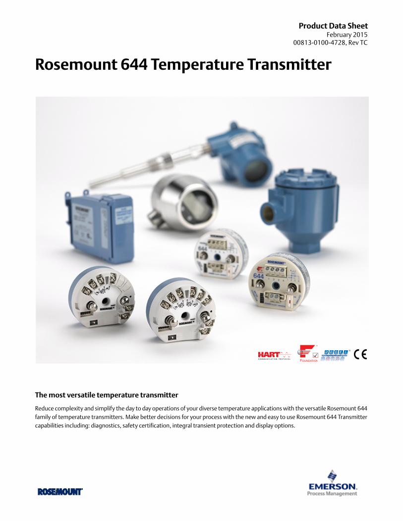
Rosemount 644 Temperature Transmitter
The most versatile temperature transmitter
Reduce complexity and simplify the day to day operations of your diverse temperature applications with the versatile Rosemount 644 family of temperature transmitters. Make better decisions for your process with the new and easy to use Rosemount 644 Transmitter capabilities including: diagnostics, safety certification, integral transient protection and display options.
Rosemount 644February 2015
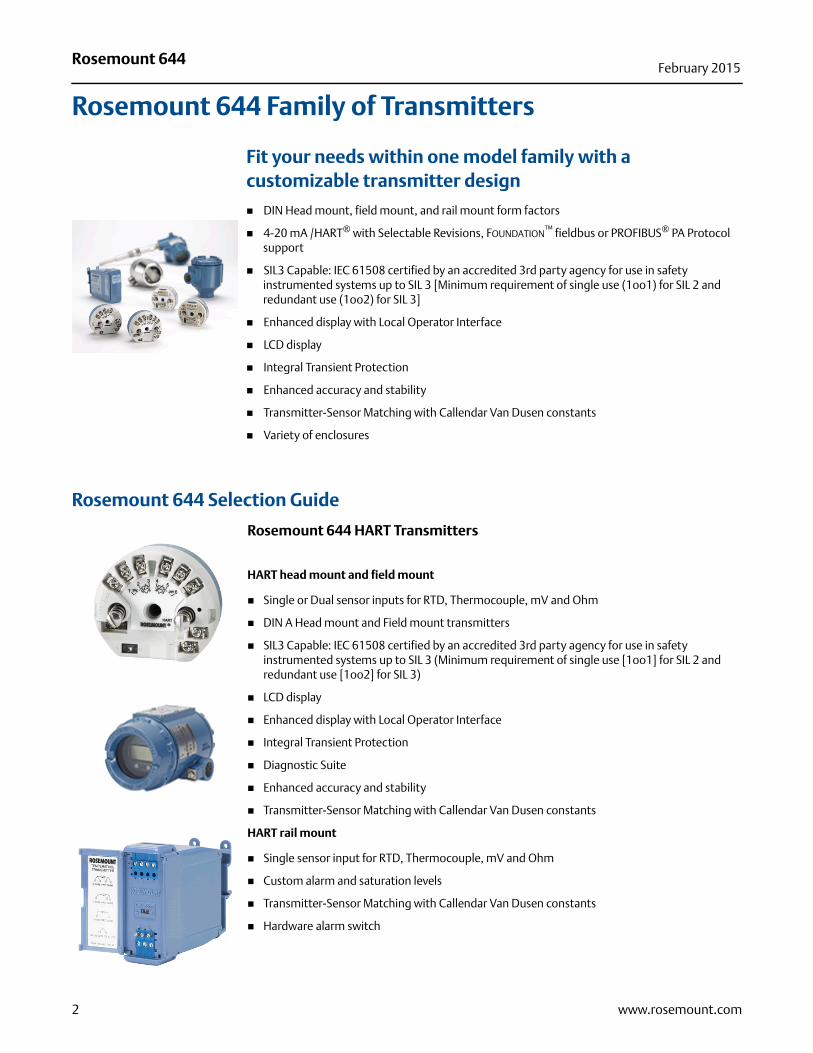
Rosemount 644 Family of Transmitters
Fit your needs within one model family with a customizable transmitter design
DIN Head mount, field mount, and rail mount form factors
4-20 mA /HART® with Selectable Revisions, FOUNDATION™ fieldbus or PROFIBUS® PA Protocol support
SIL3 Capable: IEC 61508 certified by an accredited 3rd party agency for use in safety instrumented systems up to SIL 3 [Minimum requirement of single use (1oo1) for SIL 2 and redundant use (1oo2) for SIL 3]
Enhanced display with Local Operator Interface
LCD display
Integral Transient Protection
Enhanced accuracy and stability
Transmitter-Sensor Matching with Callendar Van Dusen constants
Variety of enclosures
Rosemount 644 Selection Guide
Rosemount 644 HART Transmitters
HART head mount and field mount
Single or Dual sensor inputs for RTD, Thermocouple, mV and Ohm
DIN A Head mount and Field mount transmitters
SIL3 Capable: IEC 61508 certified by an accredited 3rd party agency for use in safety instrumented systems up to SIL 3 (Minimum requirement of single use [1oo1] for SIL 2 and redundant use [1oo2] for SIL 3)
LCD display
Enhanced display with Local Operator Interface
Integral Transient Protection
Diagnostic Suite
Enhanced accuracy and stability
Transmitter-Sensor Matching with Callendar Van Dusen constants
HART rail mount
Single sensor input for RTD, Thermocouple, mV and Ohm
Custom alarm and saturation levels
Transmitter-Sensor Matching with Callendar Van Dusen constants
Hardware alarm switch
2 www.rosemount.com
Rosemount 644February 2015
Contents
Ordering Information . . . . . . . . . . . . . . . . . . . . . . . . . . . . . . . 5
Specifications . . . . . . . . . . . . . . . . . . . . . . . . . . . . . . . . . . . . . 14
Rosemount 644 Dimensional Drawings . . . . . . . . . . . . . . . . 24
Specifications and Reference Data for 644 HART (Device
Revision 7 or Previous) . . . . . . . . . . . . . . . . . . . . . . . . . . . . . . 35
Product Certifications . . . . . . . . . . . . . . . . . . . . . . . . . . . . . . 38
3www.rosemount.com
Rosemount 644February 2015
Rosemount 644 FOUNDATION fieldbus
Single sensor input for RTD, Thermocouple, mV and Ohm
DIN A Head mount transmitter
Standard function blocks: 2 Analog Inputs, 1 PID and 1 Backup Link Active Scheduler (LAS)
LCD Display
ITK 5.01 Compliant
Transmitter Sensor Matching with Callendar Van Dusen constants
Rosemount 644 PROFIBUS PA
Single sensor input for RTD, Thermocouple, mV and Ohm
DIN A Head mount transmitter
Standard function blocks: 1 physical, 1 Transducer, and 1 Analog Out
LCD Display
Compliant to PROFIBUS PA Profile 3.02
Transmitter-Sensor Matching with Callendar Van Dusen constants
Easy to use human-centered designs to make your job simple
Diagnostic information and process health at your finger tips with intuitive Device Dashboards.
Communication clips are easily accessible when an LCD display is attached.
Easy wiring practices with captive sensor screw terminals, an optimized wiring diagram, and field mount enclosure option.
Optimize plant efficiency and increase visibility into the process with an expansive diagnostic offering
Keep your process up and running with the Hot Backup™ feature where if your primary sensor fails, a second sensor seamlessly takes over and prevents the measurement failure.
Tighten control with Sensor Drift Alert that detects drifting sensors and pro-actively notifies the user.
Enable predictive maintenance practices with Thermocouple Degradation Diagnostic that monitors the health of the thermocouple loop.
Improve quality with Minimum and Maximum Temperature Tracking that records temperature extremes of the process and the ambient environment.
4 www.rosemount.com
Rosemount 644February 2015
Ordering Information
The Rosemount 644 is a Versatile Temperature Transmitter that delivers field reliability and advanced accuracy and stability to meet demanding process needs.
Transmitter features include:
HART/4-20 mA with Selectable Revision 5 and 7 selectable (Option Code A), FOUNDATION fieldbus (Option Code F) or PROFIBUS PA (Option Code W)
DIN A Head Mount, Field Mount, or Rail Mount transmitter styles
Dual Sensor Input (Option Code S)
SIS SIL 2 Safety Certification (Option Code QT)
LCD Display (Option Code M5)
Local Operator Interface (Option Code M4)
Advanced Diagnostics (Option Codes DC and DA1)
Enhanced Transmitter Accuracy and Stability (Option Code P8)
Transmitter-Sensor Matching (Option Code C2)
Specification and selection of product materials, options, or components must be made by the purchaser of the equipment. See page 14 for more information on Material Selection.
Table 1. Rosemount 644 Smart Temperature Transmitter Ordering Information★ The Standard offering represents the most common models and options. These options should be selected for best delivery.
__The Expanded offering is manufactured after receipt of order and is subject to additional delivery lead time.
● = Available– = Not Available
Model Product description
644 Temperature Transmitter
Transmitter type
H DIN A Head Mount - Single Sensor Input ★
R Rail Mount - Single Sensor Input ★
S DIN A Head Mount - Dual Sensor Input (HART only) ★
F(1) Field Mount - Single Sensor Input (HART only) ★
D(1) Field Mount - Dual Sensor Input (HART only) ★
Output Head Rail
A 4–20 mA with digital signal based on HART protocol ● ● ★
FFOUNDATION fieldbus digital signal (includes 2 AI function blocks and Backup Link Active Scheduler)
● – ★
W PROFIBUS PA digital signal ● – ★
Product certifications Head Rail
Hazardous locations certificates (consult factory for availability(2)) A F W A
NA No approval ● ● ● ● ★
E5 FM Explosion-proof; Dust Ignition-proof ● ● ● – ★
5www.rosemount.com
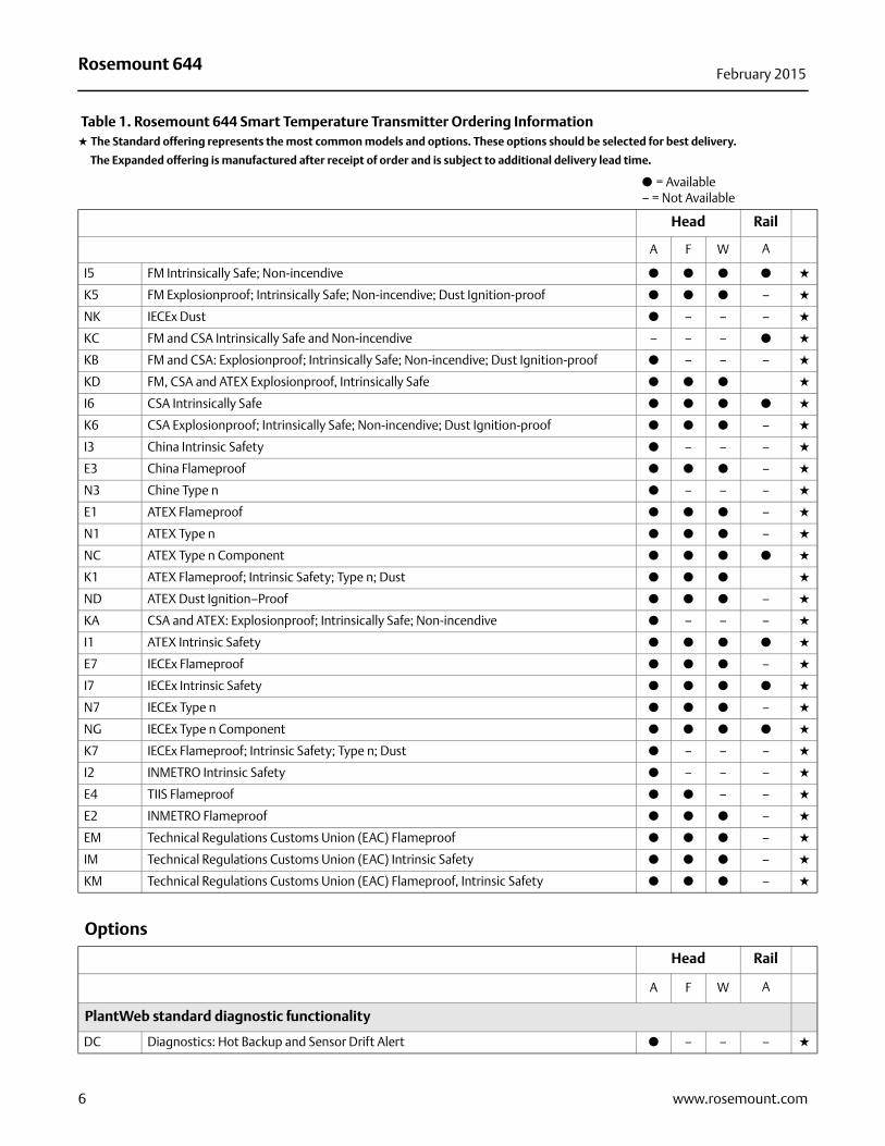
Rosemount 644February 2015
Head Rail
A F W A
I5 FM Intrinsically Safe; Non-incendive ● ● ● ● ★
K5 FM Explosionproof; Intrinsically Safe; Non-incendive; Dust Ignition-proof ● ● ● – ★
NK IECEx Dust ● – – – ★
KC FM and CSA Intrinsically Safe and Non-incendive – – – ● ★
KB FM and CSA: Explosionproof; Intrinsically Safe; Non-incendive; Dust Ignition-proof ● – – – ★
KD FM, CSA and ATEX Explosionproof, Intrinsically Safe ● ● ● ★
I6 CSA Intrinsically Safe ● ● ● ● ★
K6 CSA Explosionproof; Intrinsically Safe; Non-incendive; Dust Ignition-proof ● ● ● – ★
I3 China Intrinsic Safety ● – – – ★
E3 China Flameproof ● ● ● – ★
N3 Chine Type n ● – – – ★
E1 ATEX Flameproof ● ● ● – ★
N1 ATEX Type n ● ● ● – ★
NC ATEX Type n Component ● ● ● ● ★
K1 ATEX Flameproof; Intrinsic Safety; Type n; Dust ● ● ● ★
ND ATEX Dust Ignition–Proof ● ● ● – ★
KA CSA and ATEX: Explosionproof; Intrinsically Safe; Non-incendive ● – – – ★
I1 ATEX Intrinsic Safety ● ● ● ● ★
E7 IECEx Flameproof ● ● ● – ★
I7 IECEx Intrinsic Safety ● ● ● ● ★
N7 IECEx Type n ● ● ● – ★
NG IECEx Type n Component ● ● ● ● ★
K7 IECEx Flameproof; Intrinsic Safety; Type n; Dust ● – – – ★
I2 INMETRO Intrinsic Safety ● – – – ★
E4 TIIS Flameproof ● ● – – ★
E2 INMETRO Flameproof ● ● ● – ★
EM Technical Regulations Customs Union (EAC) Flameproof ● ● ● – ★
IM Technical Regulations Customs Union (EAC) Intrinsic Safety ● ● ● – ★
KM Technical Regulations Customs Union (EAC) Flameproof, Intrinsic Safety ● ● ● – ★
Options
Head Rail
A F W A
PlantWeb standard diagnostic functionality
DC Diagnostics: Hot Backup and Sensor Drift Alert ● – – – ★
Table 1. Rosemount 644 Smart Temperature Transmitter Ordering Information★ The Standard offering represents the most common models and options. These options should be selected for best delivery.
__The Expanded offering is manufactured after receipt of order and is subject to additional delivery lead time.
● = Available– = Not Available
6 www.rosemount.com
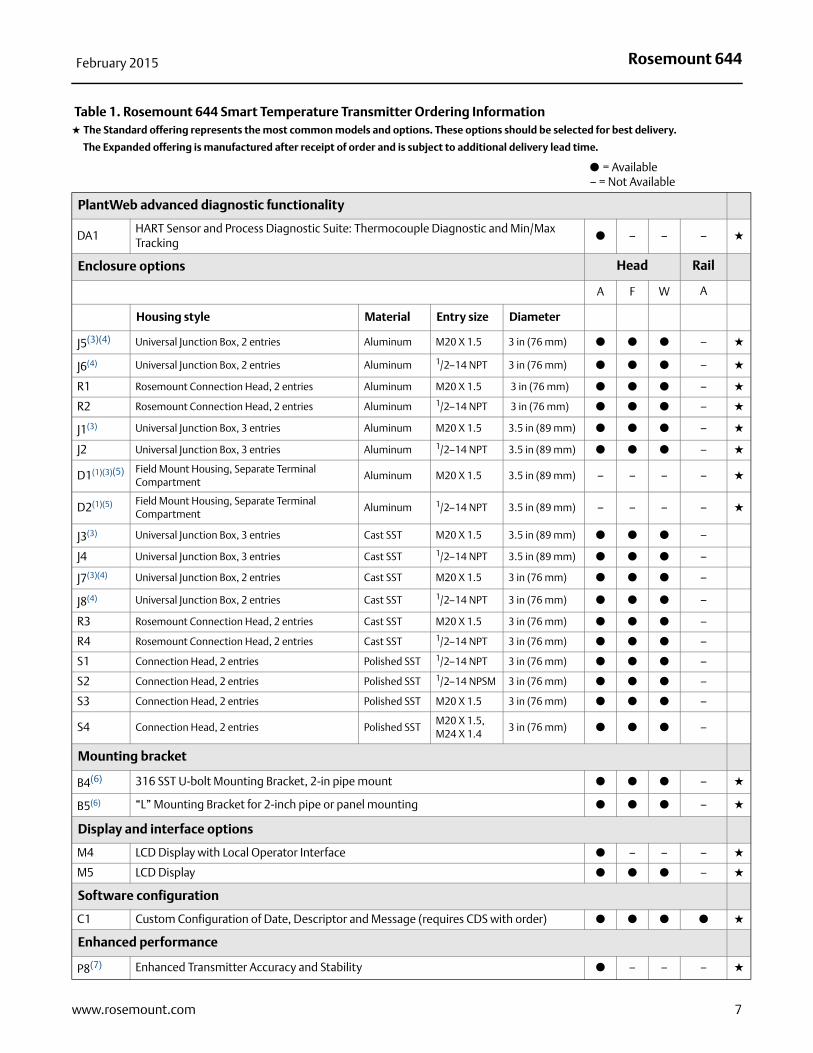
Rosemount 644February 2015
PlantWeb advanced diagnostic functionality
DA1HART Sensor and Process Diagnostic Suite: Thermocouple Diagnostic and Min/Max Tracking
● – – – ★
Enclosure options Head Rail
A F W A
Housing style Material Entry size Diameter
J5(3)(4) Universal Junction Box, 2 entries Aluminum M20 X 1.5 3 in (76 mm) ● ● ● – ★
J6(4) Universal Junction Box, 2 entries Aluminum 1/2–14 NPT 3 in (76 mm) ● ● ● – ★
R1 Rosemount Connection Head, 2 entries Aluminum M20 X 1.5 3 in (76 mm) ● ● ● – ★
R2 Rosemount Connection Head, 2 entries Aluminum 1/2–14 NPT 3 in (76 mm) ● ● ● – ★
J1(3) Universal Junction Box, 3 entries Aluminum M20 X 1.5 3.5 in (89 mm) ● ● ● – ★
J2 Universal Junction Box, 3 entries Aluminum 1/2–14 NPT 3.5 in (89 mm) ● ● ● – ★
D1(1)(3)(5) Field Mount Housing, Separate Terminal Compartment
Aluminum M20 X 1.5 3.5 in (89 mm) – – – – ★
D2(1)(5) Field Mount Housing, Separate Terminal Compartment
Aluminum 1/2–14 NPT 3.5 in (89 mm) – – – – ★
J3(3) Universal Junction Box, 3 entries Cast SST M20 X 1.5 3.5 in (89 mm) ● ● ● –
J4 Universal Junction Box, 3 entries Cast SST 1/2–14 NPT 3.5 in (89 mm) ● ● ● –
J7(3)(4) Universal Junction Box, 2 entries Cast SST M20 X 1.5 3 in (76 mm) ● ● ● –
J8(4) Universal Junction Box, 2 entries Cast SST 1/2–14 NPT 3 in (76 mm) ● ● ● –
R3 Rosemount Connection Head, 2 entries Cast SST M20 X 1.5 3 in (76 mm) ● ● ● –
R4 Rosemount Connection Head, 2 entries Cast SST 1/2–14 NPT 3 in (76 mm) ● ● ● –
S1 Connection Head, 2 entries Polished SST 1/2–14 NPT 3 in (76 mm) ● ● ● –
S2 Connection Head, 2 entries Polished SST 1/2–14 NPSM 3 in (76 mm) ● ● ● –
S3 Connection Head, 2 entries Polished SST M20 X 1.5 3 in (76 mm) ● ● ● –
S4 Connection Head, 2 entries Polished SSTM20 X 1.5,M24 X 1.4
3 in (76 mm) ● ● ● –
Mounting bracket
B4(6) 316 SST U-bolt Mounting Bracket, 2-in pipe mount ● ● ● – ★
B5(6) “L” Mounting Bracket for 2-inch pipe or panel mounting ● ● ● – ★
Display and interface options
M4 LCD Display with Local Operator Interface ● – – – ★
M5 LCD Display ● ● ● – ★
Software configuration
C1 Custom Configuration of Date, Descriptor and Message (requires CDS with order) ● ● ● ● ★
Enhanced performance
P8(7) Enhanced Transmitter Accuracy and Stability ● – – – ★
Table 1. Rosemount 644 Smart Temperature Transmitter Ordering Information★ The Standard offering represents the most common models and options. These options should be selected for best delivery.
__The Expanded offering is manufactured after receipt of order and is subject to additional delivery lead time.
● = Available– = Not Available
7www.rosemount.com
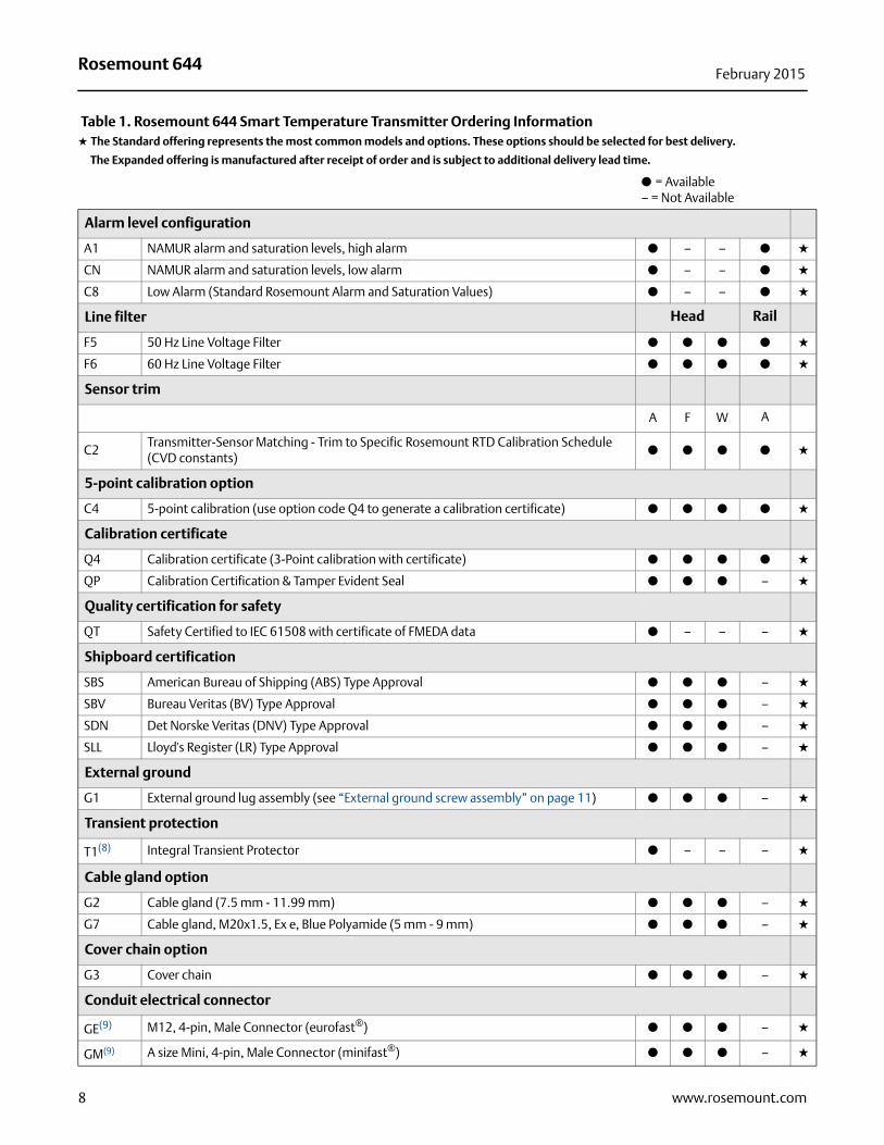
Rosemount 644February 2015
Alarm level configuration
A1 NAMUR alarm and saturation levels, high alarm ● – – ● ★
CN NAMUR alarm and saturation levels, low alarm ● – – ● ★
C8 Low Alarm (Standard Rosemount Alarm and Saturation Values) ● – – ● ★
Line filter Head Rail
F5 50 Hz Line Voltage Filter ● ● ● ● ★
F6 60 Hz Line Voltage Filter ● ● ● ● ★
Sensor trim
A F W A
C2Transmitter-Sensor Matching - Trim to Specific Rosemount RTD Calibration Schedule (CVD constants)
● ● ● ● ★
5-point calibration option
C4 5-point calibration (use option code Q4 to generate a calibration certificate) ● ● ● ● ★
Calibration certificate
Q4 Calibration certificate (3-Point calibration with certificate) ● ● ● ● ★
QP Calibration Certification & Tamper Evident Seal ● ● ● – ★
Quality certification for safety
QT Safety Certified to IEC 61508 with certificate of FMEDA data ● – – – ★
Shipboard certification
SBS American Bureau of Shipping (ABS) Type Approval ● ● ● – ★
SBV Bureau Veritas (BV) Type Approval ● ● ● – ★
SDN Det Norske Veritas (DNV) Type Approval ● ● ● – ★
SLL Lloyd's Register (LR) Type Approval ● ● ● – ★
External ground
G1 External ground lug assembly (see “External ground screw assembly” on page 11) ● ● ● – ★
Transient protection
T1(8) Integral Transient Protector ● – – – ★
Cable gland option
G2 Cable gland (7.5 mm - 11.99 mm) ● ● ● – ★
G7 Cable gland, M20x1.5, Ex e, Blue Polyamide (5 mm - 9 mm) ● ● ● – ★
Cover chain option
G3 Cover chain ● ● ● – ★
Conduit electrical connector
GE(9) M12, 4-pin, Male Connector (eurofast®) ● ● ● – ★
GM(9) A size Mini, 4-pin, Male Connector (minifast®) ● ● ● – ★
Table 1. Rosemount 644 Smart Temperature Transmitter Ordering Information★ The Standard offering represents the most common models and options. These options should be selected for best delivery.
__The Expanded offering is manufactured after receipt of order and is subject to additional delivery lead time.
● = Available– = Not Available
8 www.rosemount.com
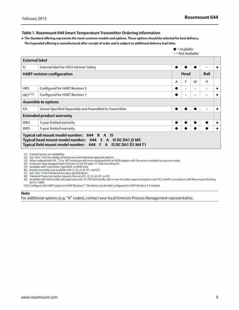
Rosemount 644February 2015
NoteFor additional options (e.g. “K” codes), contact your local Emerson Process Management representative.
External label
EL External label for ATEX Intrinsic Safety ● ● ● – ★
HART revision configuration Head Rail
A F W A
HR5 Configured for HART Revision 5 ● – – – ★
HR7(10) Configured for HART Revision 7 ● – – – ★
Assemble to options
XA Sensor Specified Separately and Assembled to Transmitter ● ● ● – ★
Extended product warranty
WR3 3-year limited warranty ● ● ● ● ★
WR5 5-year limited warranty ● ● ● ● ★
Typical rail mount model number: 644 R A I5Typical head mount model number: 644 S A I5 DC DA1 J5 M5 Typical field mount model number: 644 F A I5 DC DA1 D1 M4 T1
(1) Consult factory on availability.(2) See Table 2 for the validity of enclosures with individual approval options.(3) When ordered with XA, 1/2-in. NPT enclosure will come equipped with an M20 adapter with the sensor installed as a process ready.(4) Enclosure ships equipped with 50.8 mm (2-in) SST pipe “U” bolt mounting kit.(5) Available with Transmitter Type 644F or 644D only.(6) Bracket assembly only available with J1, J2, J3, J4, D1, and D2.(7) See Table 10 for Enhanced Accuracy specifications.(8) Transient Protection option requires the use of J1, J2, J3, J4, D1, or D2.(9) Available with Intrinsically Safe approvals only. For FM Intrinsically Safe or non-incendive approval (option code I5), install in accordance with Rosemount drawing
03151-1009.(10) Configures the HART output to HART Revision 7. The device can be field configured to HART Revision 5 if needed.
Table 1. Rosemount 644 Smart Temperature Transmitter Ordering Information★ The Standard offering represents the most common models and options. These options should be selected for best delivery.
__The Expanded offering is manufactured after receipt of order and is subject to additional delivery lead time.
● = Available– = Not Available
9www.rosemount.com
Rosemount 644February 2015
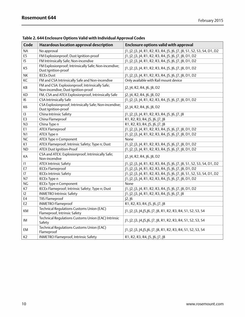
Table 2. 644 Enclosure Options Valid with Individual Approval Codes
Code Hazardous location approval description Enclosure options valid with approval
NA No approval J1, J2, J3, J4, R1, R2, R3, R4, J5, J6, J7, J8, S1, S2, S3, S4, D1, D2E5 FM Explosionproof; Dust Ignition-proof J1, J2, J3, J4, R1, R2, R3, R4, J5, J6, J7, J8, D1, D2I5 FM Intrinsically Safe; Non-incendive J1, J2, J3, J4, R1, R2, R3, R4, J5, J6, J7, J8, D1, D2
K5FM Explosionproof; Intrinsically Safe; Non-incendive; Dust Ignition-proof
J1, J2, J3, J4, R1, R2, R3, R4, J5, J6, J7, J8, D1, D2
NK IECEx Dust J1, J2, J3, J4, R1, R2, R3, R4, J5, J6, J7, J8, D1, D2KC FM and CSA Intrinsically Safe and Non-incendive Only available with Rail mount device
KBFM and CSA: Explosionproof; Intrinsically Safe; Non-incendive; Dust Ignition-proof
J2, J4, R2, R4, J6, J8, D2
KD FM, CSA and ATEX Explosionproof, Intrinsically Safe J2, J4, R2, R4, J6, J8, D2I6 CSA Intrinsically Safe J1, J2, J3, J4, R1, R2, R3, R4, J5, J6, J7, J8, D1, D2
K6CSA Explosionproof; Intrinsically Safe; Non-incendive; Dust Ignition-proof
J2, J4, R2, R4, J6, J8, D2
I3 China Intrinsic Safety J1, J2, J3, J4, R1, R2, R3, R4, J5, J6, J7, J8E3 China Flameproof R1, R2, R3, R4, J5, J6, J7, J8N3 China Type n R1, R2, R3, R4, J5, J6, J7, J8E1 ATEX Flameproof J1, J2, J3, J4, R1, R2, R3, R4, J5, J6, J7, J8, D1, D2N1 ATEX Type n J1, J2, J3, J4, R1, R2, R3, R4, J5, J6, J7, J8, D1, D2NC ATEX Type n Component NoneK1 ATEX Flameproof; Intrinsic Safety; Type n; Dust J1, J2, J3, J4, R1, R2, R3, R4, J5, J6, J7, J8, D1, D2ND ATEX Dust Ignition-Proof J1, J2, J3, J4, R1, R2, R3, R4, J5, J6, J7, J8, D1, D2
KACSA and ATEX: Explosionproof; Intrinsically Safe; Non-incendive
J2, J4, R2, R4, J6, J8, D2
I1 ATEX Intrinsic Safety J1, J2, J3, J4, R1, R2, R3, R4, J5, J6, J7, J8, S1, S2, S3, S4, D1, D2E7 IECEx Flameproof J1, J2, J3, J4, R1, R2, R3, R4, J5, J6, J7, J8, D1, D2I7 IECEx Intrinsic Safety J1, J2, J3, J4, R1, R2, R3, R4, J5, J6, J7, J8, S1, S2, S3, S4, D1, D2N7 IECEx Type n J1, J2, J3, J4, R1, R2, R3, R4, J5, J6, J7, J8, D1, D2NG IECEx Type n Component NoneK7 IECEx Flameproof; Intrinsic Safety; Type n; Dust J1, J2, J3, J4, R1, R2, R3, R4, J5, J6, J7, J8, D1, D2I2 INMETRO Intrinsic Safety J1, J2, J3, J4, R1, R2, R3, R4, J5, J6, J7, J8E4 TIIS Flameproof J2, J6E2 INMETRO Flameproof R1, R2, R3, R4, J5, J6, J7, J8
KMTechnical Regulations Customs Union (EAC) Flameproof, Intrinsic Safety
J1, J2, J3, J4,J5,J6, J7, J8, R1, R2, R3, R4, S1, S2, S3, S4
IMTechnical Regulations Customs Union (EAC) Intrinsic Safety
J1, J2, J3, J4,J5,J6, J7, J8, R1, R2, R3, R4, S1, S2, S3, S4
EMTechnical Regulations Customs Union (EAC) Flameproof
J1, J2, J3, J4,J5,J6, J7, J8, R1, R2, R3, R4, S1, S2, S3, S4
K2 INMETRO Flameproof, Intrinsic Safety R1, R2, R3, R4, J5, J6, J7, J8
10 www.rosemount.com
Rosemount 644February 2015
Tagging
Hardware
13 characters total
Tags are adhesive or metal labels
Tag is permanently attached to transmitter
Software
The transmitter can store up to 13 characters for FOUNDATION fieldbus and PROFIBUS PA or 8 for HART protocol. If no characters are specified, the first 8 characters of the hardware tag are the default. An optional 32 character Long Software Tag is available when option code HR7 is ordered.
Considerations
External ground screw assembly
The external ground screw assembly can be ordered by specifying code G1 when an enclosure is specified. However, some approvals include the ground screw assembly in the transmitter shipment, hence it is not necessary to order code G1. The table below identifies which approval options include the external ground screw assembly and which do not.
Option code External ground screw assembly included?E5, I1, I2, I5, I6, I7, K5, K6, NA, I3, KB No–Order option code G1 E1, E2, E3, E4, E7, K7, N1, N7, ND, K1, K2, KA, NK, N3, KD, T1 Yes
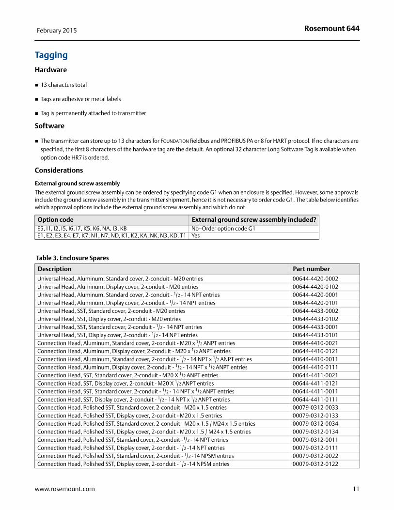
Table 3. Enclosure Spares
Description Part number
Universal Head, Aluminum, Standard cover, 2-conduit - M20 entries 00644-4420-0002Universal Head, Aluminum, Display cover, 2-conduit - M20 entries 00644-4420-0102Universal Head, Aluminum, Standard cover, 2-conduit - 1/2 - 14 NPT entries 00644-4420-0001Universal Head, Aluminum, Display cover, 2-conduit - 1/2 - 14 NPT entries 00644-4420-0101Universal Head, SST, Standard cover, 2-conduit - M20 entries 00644-4433-0002Universal Head, SST, Display cover, 2-conduit - M20 entries 00644-4433-0102Universal Head, SST, Standard cover, 2-conduit - 1/2 - 14 NPT entries 00644-4433-0001Universal Head, SST, Display cover, 2-conduit - 1/2 - 14 NPT entries 00644-4433-0101Connection Head, Aluminum, Standard cover, 2-conduit - M20 x 1/2 ANPT entries 00644-4410-0021Connection Head, Aluminum, Display cover, 2-conduit - M20 x 1/2 ANPT entries 00644-4410-0121Connection Head, Aluminum, Standard cover, 2-conduit - 1/2 - 14 NPT x 1/2 ANPT entries 00644-4410-0011Connection Head, Aluminum, Display cover, 2-conduit - 1/2 - 14 NPT x 1/2 ANPT entries 00644-4410-0111Connection Head, SST, Standard cover, 2-conduit - M20 X 1/2 ANPT entries 00644-4411-0021Connection Head, SST, Display cover, 2-conduit - M20 X 1/2 ANPT entries 00644-4411-0121Connection Head, SST, Standard cover, 2-conduit - 1/2 - 14 NPT x 1/2 ANPT entries 00644-4411-0011Connection Head, SST, Display cover, 2-conduit - 1/2 - 14 NPT x 1/2 ANPT entries 00644-4411-0111Connection Head, Polished SST, Standard cover, 2-conduit - M20 x 1.5 entries 00079-0312-0033Connection Head, Polished SST, Display cover, 2-conduit - M20 x 1.5 entries 00079-0312-0133Connection Head, Polished SST, Standard cover, 2-conduit - M20 x 1.5 / M24 x 1.5 entries 00079-0312-0034Connection Head, Polished SST, Display cover, 2-conduit - M20 x 1.5 / M24 x 1.5 entries 00079-0312-0134Connection Head, Polished SST, Standard cover, 2-conduit -1/2 -14 NPT entries 00079-0312-0011Connection Head, Polished SST, Display cover, 2-conduit - 1/2 -14 NPT entries 00079-0312-0111Connection Head, Polished SST, Standard cover, 2-conduit - 1/2 -14 NPSM entries 00079-0312-0022Connection Head, Polished SST, Display cover, 2-conduit - 1/2 -14 NPSM entries 00079-0312-0122
11www.rosemount.com
Rosemount 644February 2015
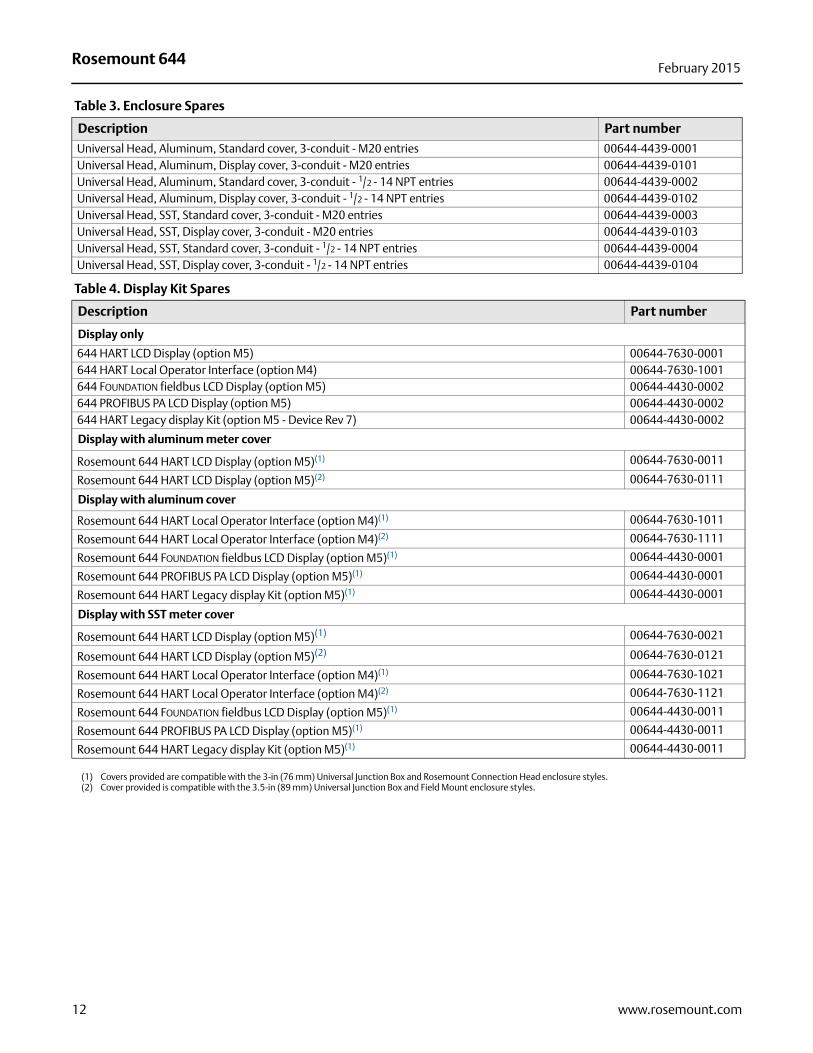
Universal Head, Aluminum, Standard cover, 3-conduit - M20 entries 00644-4439-0001Universal Head, Aluminum, Display cover, 3-conduit - M20 entries 00644-4439-0101Universal Head, Aluminum, Standard cover, 3-conduit - 1/2 - 14 NPT entries 00644-4439-0002Universal Head, Aluminum, Display cover, 3-conduit - 1/2 - 14 NPT entries 00644-4439-0102 Universal Head, SST, Standard cover, 3-conduit - M20 entries 00644-4439-0003Universal Head, SST, Display cover, 3-conduit - M20 entries 00644-4439-0103Universal Head, SST, Standard cover, 3-conduit - 1/2 - 14 NPT entries 00644-4439-0004Universal Head, SST, Display cover, 3-conduit - 1/2 - 14 NPT entries 00644-4439-0104
Table 4. Display Kit Spares
Description Part number
Display only
644 HART LCD Display (option M5) 00644-7630-0001644 HART Local Operator Interface (option M4) 00644-7630-1001644 FOUNDATION fieldbus LCD Display (option M5) 00644-4430-0002644 PROFIBUS PA LCD Display (option M5) 00644-4430-0002644 HART Legacy display Kit (option M5 - Device Rev 7) 00644-4430-0002
Display with aluminum meter cover
Rosemount 644 HART LCD Display (option M5)(1) 00644-7630-0011
Rosemount 644 HART LCD Display (option M5)(2) 00644-7630-0111
Display with aluminum cover
Rosemount 644 HART Local Operator Interface (option M4)(1) 00644-7630-1011
Rosemount 644 HART Local Operator Interface (option M4)(2) 00644-7630-1111
Rosemount 644 FOUNDATION fieldbus LCD Display (option M5)(1) 00644-4430-0001
Rosemount 644 PROFIBUS PA LCD Display (option M5)(1) 00644-4430-0001
Rosemount 644 HART Legacy display Kit (option M5)(1) 00644-4430-0001
Display with SST meter cover
Rosemount 644 HART LCD Display (option M5)(1) 00644-7630-0021
Rosemount 644 HART LCD Display (option M5)(2) 00644-7630-0121
Rosemount 644 HART Local Operator Interface (option M4)(1) 00644-7630-1021
Rosemount 644 HART Local Operator Interface (option M4)(2) 00644-7630-1121
Rosemount 644 FOUNDATION fieldbus LCD Display (option M5)(1) 00644-4430-0011
Rosemount 644 PROFIBUS PA LCD Display (option M5)(1) 00644-4430-0011
Rosemount 644 HART Legacy display Kit (option M5)(1) 00644-4430-0011
(1) Covers provided are compatible with the 3-in (76 mm) Universal Junction Box and Rosemount Connection Head enclosure styles.(2) Cover provided is compatible with the 3.5-in (89 mm) Universal Junction Box and Field Mount enclosure styles.
Table 3. Enclosure Spares
Description Part number
12 www.rosemount.com
Rosemount 644February 2015
13www.rosemount.com
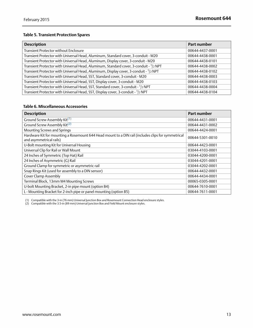
Table 5. Transient Protection Spares
Description Part number
Transient Protector without Enclosure 00644-4437-0001Transient Protector with Universal Head, Aluminum, Standard cover, 3-conduit - M20 00644-4438-0001 Transient Protector with Universal Head, Aluminum, Display cover, 3-conduit - M20 00644-4438-0101 Transient Protector with Universal Head, Aluminum, Standard cover, 3-conduit - 1/2 NPT 00644-4438-0002 Transient Protector with Universal Head, Aluminum, Display cover, 3-conduit - 1/2 NPT 00644-4438-0102 Transient Protector with Universal Head, SST, Standard cover, 3-conduit - M20 00644-4438-0003Transient Protector with Universal Head, SST, Display cover, 3-conduit - M20 00644-4438-0103Transient Protector with Universal Head, SST, Standard cover, 3-conduit - 1/2 NPT 00644-4438-0004Transient Protector with Universal Head, SST, Display cover, 3-conduit - 1/2 NPT 00644-4438-0104
Table 6. Miscellaneous Accessories
Description Part number
Ground Screw Assembly Kit(1) 00644-4431-0001Ground Screw Assembly Kit(2) 00644-4431-0002Mounting Screws and Springs 00644-4424-0001Hardware Kit for mounting a Rosemount 644 Head mount to a DIN rail (includes clips for symmetrical and asymmetrical rails)
00644-5301-0010
U-Bolt mounting Kit for Universal Housing 00644-4423-0001Universal Clip for Rail or Wall Mount 03044-4103-000124 Inches of Symmetric (Top Hat) Rail 03044-4200-000124 Inches of Asymmetric (G) Rail 03044-4201-0001Ground Clamp for symmetric or asymmetric rail 03044-4202-0001Snap Rings Kit (used for assembly to a DIN sensor) 00644-4432-0001Cover Clamp Assembly 00644-4434-0001Terminal Block, 13mm M4 Mounting Screws 00065-0305-0001U-bolt Mounting Bracket, 2-in pipe mount (option B4) 00644-7610-0001L - Mounting Bracket for 2-inch pipe or panel mounting (option B5) 00644-7611-0001
(1) Compatible with the 3-in (76 mm) Universal Junction Box and Rosemount Connection Head enclosure styles.(2) Compatible with the 3.5-in (89 mm) Universal Junction Box and Field Mount enclosure styles.
Rosemount 644February 2015
Specifications
HART, FOUNDATION fieldbus, and PROFIBUS PA
Functional specifications
InputsUser-selectable; sensor terminals rated to 42.4 Vdc. See “Accuracy” on page 20 for sensor options.
OutputSingle 2-wire device with either 4–20 mA/HART, linear with temperature or input; or completely digital outputs with FOUNDATION fieldbus communication (ITK 5.01 compliant), or PROFIBUS PA (compliant with profile 3.02).
IsolationInput/output isolation tested to 600 Vrms.
Local display options
LCD displayAn optional 11 digit, 2 line integral LCD display operates with a floating or fixed decimal point. It displays engineering units (°F, °C, °R, K, Ohms and mV), mA, and percent of range. The display can be configured to alternate between selected display options. Display settings are pre-configured at the factory according to the standard transmitter configuration. They can be re-configured in the field using either HART, FOUNDATION fieldbus, or PROFIBUS PA communications.
LCD display with local operator interfaceAn optional 14-digit, 2-line integral LCD display operates with a floating or fixed decimal point. The LOI includes all features and functionality available in the regular display with an added 2-button configuration capability directly at the display interface. The LOI also has optional password protection for secure operations. The LOI is only available on the 644 HART Head mount and Field mount transmitters.
For more information on the LOI configuration options or further functionality that the LOI offers, see Appendix D: Local Operator Interface (LOI) in the Rosemount 644 Temperature Transmitter Product Manual (00809-0200-4728), available on rosemount.com.
Humidity limits0–95% relative humidity
Update time≤ 0.5 sec. per sensor
Accuracy (default configuration) PT 100HART Standard: ±0.15 °CHART Enhanced: ±0.1 °CFOUNDATION fieldbus: ±0.15 °CPROFIBUS PA: ±0.15 °C
Physical specifications
Material selectionEmerson provides a variety of Rosemount product with various product options and configurations including materials of construction that can be expected to perform well in a wide range of applications. The Rosemount product information presented is intended as a guide for the purchaser to make an appropriate selection for the application. It is the purchaser’s sole responsibility to make a careful analysis of all process parameters (such as all chemical components, temperature, pressure, flow rate, abrasives, contaminants, etc.), when specifying product, materials, options and components for the particular application. Emerson Process Management is not in a position to evaluate or guarantee the compatibility of the process fluid or other process parameters with the product, options, configuration or materials of construction selected.
Conformance to specifications (±3σ [Sigma])Technology leadership, advanced manufacturing techniques, and statistical process control ensure specification conformance to at least ±3σ.
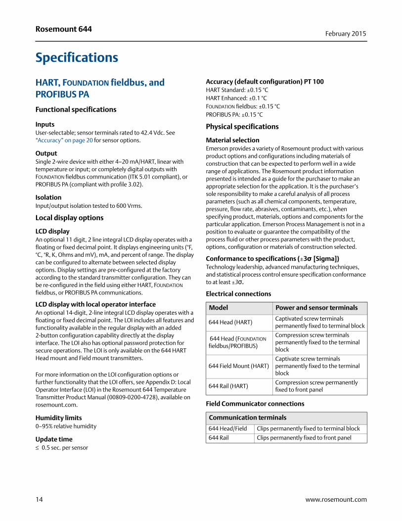
Electrical connections
Field Communicator connections
Model Power and sensor terminals
644 Head (HART)Captivated screw terminals permanently fixed to terminal block
644 Head (FOUNDATION fieldbus/PROFIBUS)
Compression screw terminals permanently fixed to the terminal block
644 Field Mount (HART)Captivate screw terminals permanently fixed to the terminal block
644 Rail (HART)Compression screw permanently fixed to front panel
Communication terminals
644 Head/Field Clips permanently fixed to terminal block
644 Rail Clips permanently fixed to front panel
14 www.rosemount.com
Rosemount 644February 2015
Materials of construction
Materials of construction (stainless steel housing for biotechnology, pharmaceutical industries, and sanitary applications)
Housing and standard meter cover
316 SST
Cover O-ring
Buna-N
MountingThe 644R attaches directly to a wall or a DIN rail. The 644H installs in a connection head or universal head mounted directly on a sensor assembly, apart from a sensor assembly using a universal head, or to a DIN rail using an optional mounting clip.
Special mounting considerationsSee “Mounting kits for 644H” on page 26 for the special hardware that is available to:
Mount a 644H to a DIN rail. (see Table 3 on page 11)
Retrofit a new 644H to replace an existing 644H Transmitter in an existing threaded sensor connection head. (see Table 3 on page 11)
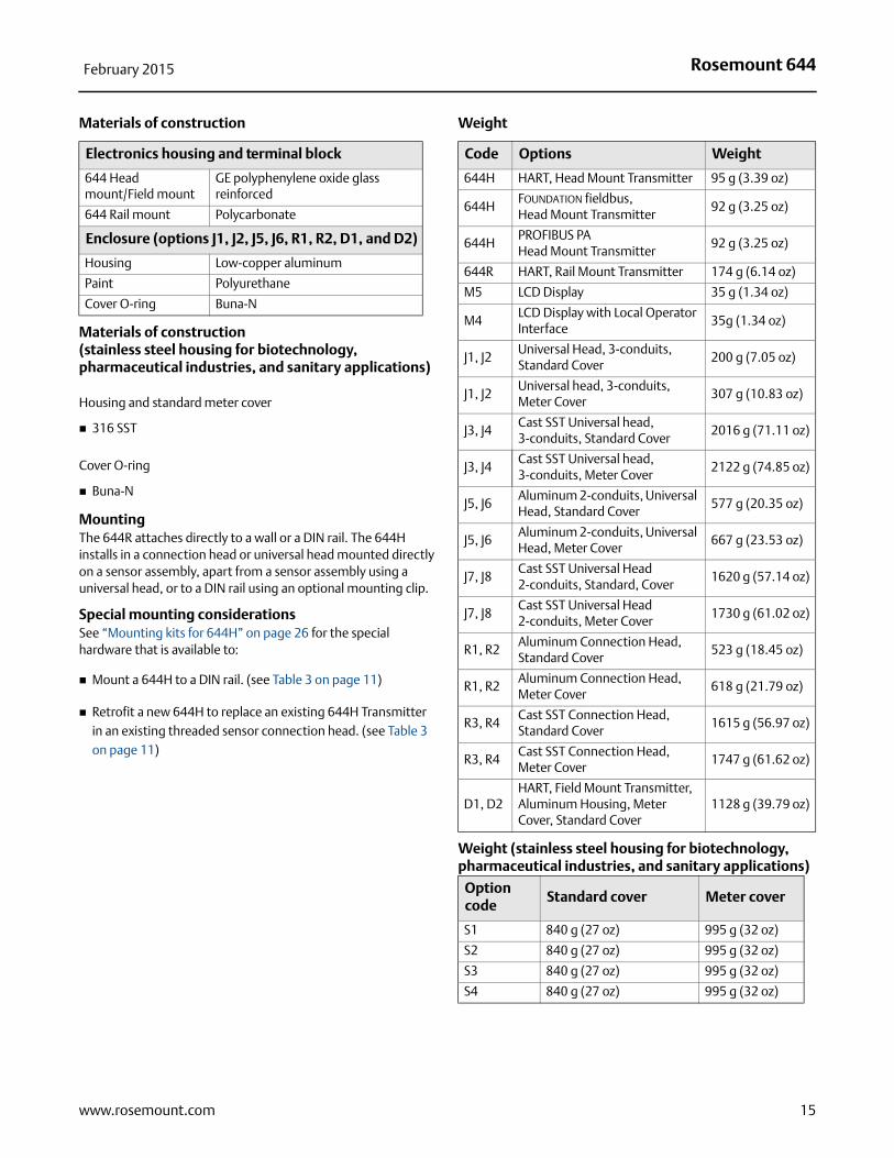
Weight
Weight (stainless steel housing for biotechnology, pharmaceutical industries, and sanitary applications)
Electronics housing and terminal block
644 Head mount/Field mount
GE polyphenylene oxide glass reinforced
644 Rail mount Polycarbonate
Enclosure (options J1, J2, J5, J6, R1, R2, D1, and D2)
Housing Low-copper aluminum
Paint Polyurethane
Cover O-ring Buna-N
Code Options Weight
644H HART, Head Mount Transmitter 95 g (3.39 oz)
644HFOUNDATION fieldbus, Head Mount Transmitter
92 g (3.25 oz)
644HPROFIBUS PAHead Mount Transmitter
92 g (3.25 oz)
644R HART, Rail Mount Transmitter 174 g (6.14 oz)
M5 LCD Display 35 g (1.34 oz)
M4LCD Display with Local Operator Interface
35g (1.34 oz)
J1, J2Universal Head, 3-conduits, Standard Cover
200 g (7.05 oz)
J1, J2Universal head, 3-conduits, Meter Cover
307 g (10.83 oz)
J3, J4Cast SST Universal head, 3-conduits, Standard Cover
2016 g (71.11 oz)
J3, J4Cast SST Universal head, 3-conduits, Meter Cover
2122 g (74.85 oz)
J5, J6Aluminum 2-conduits, Universal Head, Standard Cover
577 g (20.35 oz)
J5, J6Aluminum 2-conduits, Universal Head, Meter Cover
667 g (23.53 oz)
J7, J8Cast SST Universal Head 2-conduits, Standard, Cover
1620 g (57.14 oz)
J7, J8Cast SST Universal Head 2-conduits, Meter Cover
1730 g (61.02 oz)
R1, R2Aluminum Connection Head, Standard Cover
523 g (18.45 oz)
R1, R2Aluminum Connection Head, Meter Cover
618 g (21.79 oz)
R3, R4Cast SST Connection Head, Standard Cover
1615 g (56.97 oz)
R3, R4Cast SST Connection Head, Meter Cover
1747 g (61.62 oz)
D1, D2HART, Field Mount Transmitter, Aluminum Housing, Meter Cover, Standard Cover
1128 g (39.79 oz)
Option code
Standard cover Meter cover
S1 840 g (27 oz) 995 g (32 oz)
S2 840 g (27 oz) 995 g (32 oz)
S3 840 g (27 oz) 995 g (32 oz)
S4 840 g (27 oz) 995 g (32 oz)
15www.rosemount.com
Rosemount 644February 2015
Enclosure ratings (644H/F)All available enclosures are Type 4X, IP66, and IP68.
Sanitary housing surfaceSurface finish is polished to 32 RMA. Laser etched product marking on housing and standard covers.
Performance specifications
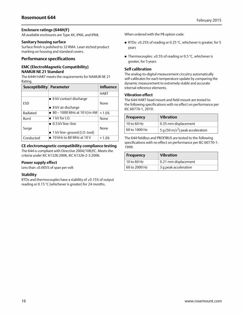
EMC (ElectroMagnetic Compatibility)NAMUR NE 21 StandardThe 644H HART meets the requirements for NAMUR NE 21 Rating.
CE electromagnetic compatibility compliance testingThe 644 is compliant with Directive 2004/108/EC. Meets the criteria under IEC 61326:2006, IEC 61326-2-3:2006.
Power supply effectLess than ±0.005% of span per volt
StabilityRTDs and thermocouples have a stability of ±0.15% of output reading or 0.15 °C (whichever is greater) for 24 months.
When ordered with the P8 option code:
RTDs: ±0.25% of reading or 0.25 °C, whichever is greater, for 5 years
Thermocouples: ±0.5% of reading or 0.5 °C, whichever is greater, for 5 years
Self calibrationThe analog-to-digital measurement circuitry automatically self-calibrates for each temperature update by comparing the dynamic measurement to extremely stable and accurate internal reference elements.
Vibration effectThe 644 HART head mount and field mount are tested to the following specifications with no effect on performance per IEC 60770-1, 2010:
The 644 fieldbus and PROFIBUS are tested to the following specifications with no effect on performance per IEC 60770-1: 1999:
Susceptibility Parameter Influence
HART
ESD 6 kV contact discharge
8 kV air dischargeNone
Radiated 80 – 1000 MHz at 10 V/m AM < 1.0%
Burst 1 kV for I.O. None
Surge 0.5 kV line–line
1 kV line–ground (I.O. tool)None
Conducted 10 kHz to 80 MHz at 10 V < 1.0%
Frequency Vibration
10 to 60 Hz 0.35 mm displacement
60 to 1000 Hz 5 g (50 m/s2) peak acceleration
Frequency Vibration
10 to 60 Hz 0.21 mm displacement
60 to 2000 Hz 3 g peak acceleration
16 www.rosemount.com
Rosemount 644February 2015
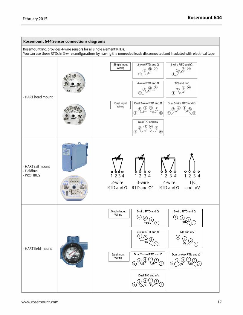
Rosemount 644 Sensor connections diagrams
Rosemount Inc. provides 4-wire sensors for all single element RTDs.You can use these RTDs in 3-wire configurations by leaving the unneeded leads disconnected and insulated with electrical tape.
- HART head mount
- HART rail mount- Fieldbus- PROFIBUS
- HART field mount
– + + –
1
2-wireRTD and Ω
3-wireRTD and Ω*
4-wireRTD and Ω
T/C and mV
2 3 4 4 4 43 3 32 2 21 1 1
17www.rosemount.com
Rosemount 644February 2015
FOUNDATION fieldbus specifications
Function blocks
Resource block
The resource block contains physical transmitter information including available memory, manufacture identification, device type, software tag, and unique identification.
Transducer block
The transducer block contains the actual temperature measurement data, including sensor 1 and terminal temperature. It includes information about sensor type and configuration, engineering units, linearization, reranging, damping, temperature correction, and diagnostics.
LCD display block
The LCD display block is used to configure the local display, if an LCD display is being used.
Analog input (AI)
Processes the measurement and makes it available on the fieldbus segment.
Allows filtering, alarming, and engineering unit changes.
PID block
The transmitter provides control functionality with one PID function block in the transmitter. The PID block can be used to perform single loop, cascade, or feedforward control in the field.
Turn-on timePerformance within specifications in less than 20 seconds after power is applied, when damping value is set to 0 seconds.
StatusIf self-diagnostics detect a sensor burnout or a transmitter failure, the status of the measurement will be updated accordingly. Status may also send the AI output to a safe value.
Power supply Powered over FOUNDATION fieldbus with standard fieldbus power supplies. The transmitter operates between 9.0 and 32.0 Vdc, 12 mA maximum.
AlarmsThe AI function block allows the user to configure the alarms to HI-HI, HI, LO, or LO-LO with hysteresis settings.
Backup Link Active Scheduler (LAS)The transmitter is classified as a device link master, which means it can function as a Link Active Scheduler (LAS) if the current link master device fails or is removed from the segment.The host or other configuration tool is used to download the schedule for the application to the link master device. In the absence of a primary link master, the transmitter will claim the LAS and provide permanent control for the H1 segment.
FOUNDATION fieldbus parameters
PROFIBUS PA specifications
Function blocks
Physical block
The Physical Block contains physical transmitter information including manufacturer identification, device type, software tag, and unique identification.
Transducer block
The Transducer Block contains the actual temperature measurement data, including sensor 1 and terminal temperature. It includes information about sensor type and configuration, engineering units, linearization, re-ranging, damping, temperature correction, and diagnostics.
Analog input block (AI)
The Analog Input Block processes the measurement and makes it available on the PROFIBUS segment. Allows filtering, alarming, and engineering unit changes.
Turn-on timePerformance within specifications in less than 20 seconds after power is applied, when damping value is set to 0 seconds.
Power supplyPowered over PROFIBUS with standard fieldbus power supplies. The transmitter operates between 9.0 and 32.0 Vdc,12 mA maximum.
AlarmsThe AI function block allows the user to configure the alarms to HI-HI, HI, LO, or LO-LO with hysteresis settings.
Block Execution time (milliseconds)
Resource N/ATransducer N/ALCD display Block N/AAnalog Input 1 45Analog Input 2 45PID 1 60
Schedule Entries 25
Links 16
Virtual Communications Relationships (VCR) 12
18 www.rosemount.com
Rosemount 644February 2015
4–20 mA/HART specifications
Power supply
External power supply required. Transmitters operate on 12.0 to 42.4 Vdc transmitter terminal voltage (with 250 ohm load, 18.1 Vdc power supply voltage is required). Transmitter power terminals rated to 42.4 Vdc.
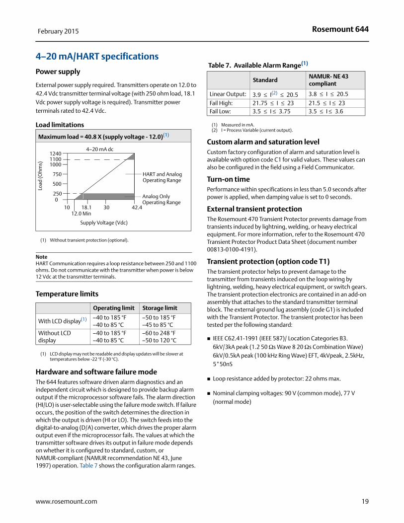
Load limitations
NoteHART Communication requires a loop resistance between 250 and 1100 ohms. Do not communicate with the transmitter when power is below 12 Vdc at the transmitter terminals.
Temperature limits
Hardware and software failure modeThe 644 features software driven alarm diagnostics and an independent circuit which is designed to provide backup alarm output if the microprocessor software fails. The alarm direction (HI/LO) is user-selectable using the failure mode switch. If failure occurs, the position of the switch determines the direction in which the output is driven (HI or LO). The switch feeds into the digital-to-analog (D/A) converter, which drives the proper alarm output even if the microprocessor fails. The values at which the transmitter software drives its output in failure mode depends on whether it is configured to standard, custom, or NAMUR-compliant (NAMUR recommendation NE 43, June 1997) operation. Table 7 shows the configuration alarm ranges.
Custom alarm and saturation levelCustom factory configuration of alarm and saturation level is available with option code C1 for valid values. These values can also be configured in the field using a Field Communicator.
Turn-on timePerformance within specifications in less than 5.0 seconds after power is applied, when damping value is set to 0 seconds.
External transient protectionThe Rosemount 470 Transient Protector prevents damage from transients induced by lightning, welding, or heavy electrical equipment. For more information, refer to the Rosemount 470 Transient Protector Product Data Sheet (document number 00813-0100-4191).
Transient protection (option code T1)The transient protector helps to prevent damage to the transmitter from transients induced on the loop wiring by lightning, welding, heavy electrical equipment, or switch gears. The transient protection electronics are contained in an add-on assembly that attaches to the standard transmitter terminal block. The external ground lug assembly (code G1) is included with the Transient Protector. The transient protector has been tested per the following standard:
IEEE C62.41-1991 (IEEE 587)/ Location Categories B3. 6kV/3kA peak (1.2 50 Ωs Wave 8 20 Ωs Combination Wave) 6kV/0.5kA peak (100 kHz Ring Wave) EFT, 4kVpeak, 2.5kHz, 5*50nS
Loop resistance added by protector: 22 ohms max.
Nominal clamping voltages: 90 V (common mode), 77 V (normal mode)
Maximum load = 40.8 X (supply voltage - 12.0)(1)
(1) Without transient protection (optional).
Operating limit Storage limit
With LCD display(1)
(1) LCD display may not be readable and display updates will be slower at temperatures below -22 °F (-30 °C).
–40 to 185 °F–40 to 85 °C
–50 to 185 °F–45 to 85 °C
Without LCD display
–40 to 185 °F–40 to 85 °C
–60 to 248 °F–50 to 120 °C
1240
1000
750
2500
1012.0 Min
18.1 30 42.4
Supply Voltage (Vdc)
HART and Analog Operating Range
4–20 mA dc
Load
(Ohm
s)
500
1100
Analog Only Operating Range
Table 7. Available Alarm Range(1)
(1) Measured in mA.
Standard NAMUR- NE 43 compliant
Linear Output: 3.9 ≤ I(2) ≤ 20.5
(2) I = Process Variable (current output).
3.8 ≤ I ≤ 20.5
Fail High: 21.75 ≤ I ≤ 23 21.5 ≤ I ≤ 23 Fail Low: 3.5 ≤ I ≤ 3.75 3.5 ≤ I ≤ 3.6
19www.rosemount.com
Rosemount 644February 2015
Accuracy
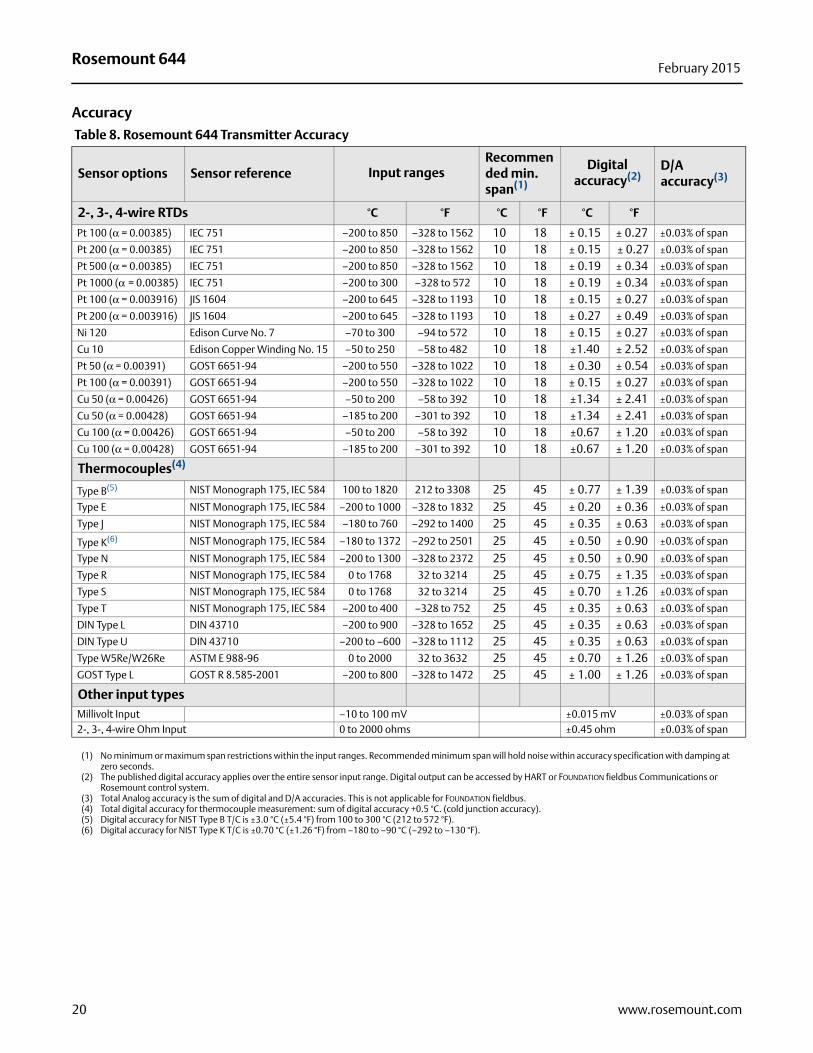
Table 8. Rosemount 644 Transmitter Accuracy
Sensor options Sensor reference Input rangesRecommended min. span(1)
Digital accuracy(2)
D/A accuracy(3)
2-, 3-, 4-wire RTDs °C °F °C °F °C °F
Pt 100 (α = 0.00385) IEC 751 –200 to 850 –328 to 1562 10 18 ± 0.15 ± 0.27 ±0.03% of span
Pt 200 (α = 0.00385) IEC 751 –200 to 850 –328 to 1562 10 18 ± 0.15 ± 0.27 ±0.03% of span
Pt 500 (α = 0.00385) IEC 751 –200 to 850 –328 to 1562 10 18 ± 0.19 ± 0.34 ±0.03% of span
Pt 1000 (α = 0.00385) IEC 751 –200 to 300 –328 to 572 10 18 ± 0.19 ± 0.34 ±0.03% of span
Pt 100 (α = 0.003916) JIS 1604 –200 to 645 –328 to 1193 10 18 ± 0.15 ± 0.27 ±0.03% of span
Pt 200 (α = 0.003916) JIS 1604 –200 to 645 –328 to 1193 10 18 ± 0.27 ± 0.49 ±0.03% of span
Ni 120 Edison Curve No. 7 –70 to 300 –94 to 572 10 18 ± 0.15 ± 0.27 ±0.03% of span
Cu 10 Edison Copper Winding No. 15 –50 to 250 –58 to 482 10 18 ±1.40 ± 2.52 ±0.03% of span
Pt 50 (α = 0.00391) GOST 6651-94 –200 to 550 –328 to 1022 10 18 ± 0.30 ± 0.54 ±0.03% of span
Pt 100 (α = 0.00391) GOST 6651-94 –200 to 550 –328 to 1022 10 18 ± 0.15 ± 0.27 ±0.03% of span
Cu 50 (α = 0.00426) GOST 6651-94 –50 to 200 –58 to 392 10 18 ±1.34 ± 2.41 ±0.03% of span
Cu 50 (α = 0.00428) GOST 6651-94 –185 to 200 –301 to 392 10 18 ±1.34 ± 2.41 ±0.03% of span
Cu 100 (α = 0.00426) GOST 6651-94 –50 to 200 –58 to 392 10 18 ±0.67 ± 1.20 ±0.03% of span
Cu 100 (α = 0.00428) GOST 6651-94 –185 to 200 –301 to 392 10 18 ±0.67 ± 1.20 ±0.03% of span
Thermocouples(4)
Type B(5) NIST Monograph 175, IEC 584 100 to 1820 212 to 3308 25 45 ± 0.77 ± 1.39 ±0.03% of span
Type E NIST Monograph 175, IEC 584 –200 to 1000 –328 to 1832 25 45 ± 0.20 ± 0.36 ±0.03% of span
Type J NIST Monograph 175, IEC 584 –180 to 760 –292 to 1400 25 45 ± 0.35 ± 0.63 ±0.03% of span
Type K(6) NIST Monograph 175, IEC 584 –180 to 1372 –292 to 2501 25 45 ± 0.50 ± 0.90 ±0.03% of span
Type N NIST Monograph 175, IEC 584 –200 to 1300 –328 to 2372 25 45 ± 0.50 ± 0.90 ±0.03% of span
Type R NIST Monograph 175, IEC 584 0 to 1768 32 to 3214 25 45 ± 0.75 ± 1.35 ±0.03% of span
Type S NIST Monograph 175, IEC 584 0 to 1768 32 to 3214 25 45 ± 0.70 ± 1.26 ±0.03% of span
Type T NIST Monograph 175, IEC 584 –200 to 400 –328 to 752 25 45 ± 0.35 ± 0.63 ±0.03% of span
DIN Type L DIN 43710 –200 to 900 –328 to 1652 25 45 ± 0.35 ± 0.63 ±0.03% of span
DIN Type U DIN 43710 –200 to –600 –328 to 1112 25 45 ± 0.35 ± 0.63 ±0.03% of span
Type W5Re/W26Re ASTM E 988-96 0 to 2000 32 to 3632 25 45 ± 0.70 ± 1.26 ±0.03% of span
GOST Type L GOST R 8.585-2001 –200 to 800 –328 to 1472 25 45 ± 1.00 ± 1.26 ±0.03% of span
Other input typesMillivolt Input –10 to 100 mV ±0.015 mV ±0.03% of span2-, 3-, 4-wire Ohm Input 0 to 2000 ohms ±0.45 ohm ±0.03% of span
(1) No minimum or maximum span restrictions within the input ranges. Recommended minimum span will hold noise within accuracy specification with damping at zero seconds.
(2) The published digital accuracy applies over the entire sensor input range. Digital output can be accessed by HART or FOUNDATION fieldbus Communications or Rosemount control system.
(3) Total Analog accuracy is the sum of digital and D/A accuracies. This is not applicable for FOUNDATION fieldbus.(4) Total digital accuracy for thermocouple measurement: sum of digital accuracy +0.5 °C. (cold junction accuracy).(5) Digital accuracy for NIST Type B T/C is ±3.0 °C (±5.4 °F) from 100 to 300 °C (212 to 572 °F).(6) Digital accuracy for NIST Type K T/C is ±0.70 °C (±1.26 °F) from –180 to –90 °C (–292 to –130 °F).
20 www.rosemount.com
Rosemount 644February 2015
Accuracy example (HART devices)When using a Pt 100 (α = 0.00385) sensor input with a 0 to100 °C span:
Digital accuracy = ±0.15 °C
D/A accuracy = ±0.03% of 100 °C or ±0.03 °C
Total accuracy = ±0.18 °C
Accuracy example (FOUNDATION fieldbus and PROFIBUS PA devices)When using a Pt 100 (α = 0.00385) sensor input:
Total accuracy = ±0.15 °C
No D/A accuracy effects apply.
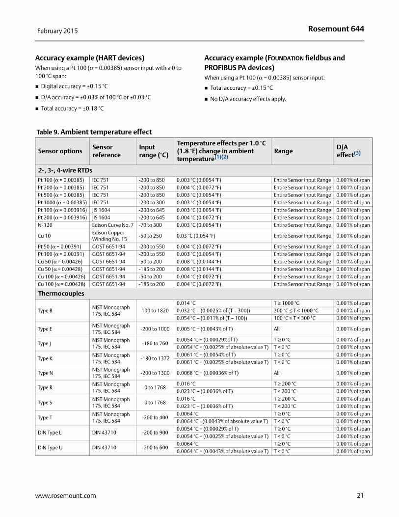
Table 9. Ambient temperature effect
Sensor optionsSensor reference
Input range (°C)
Temperature effects per 1.0 °C (1.8 °F) change in ambient temperature(1)(2)
RangeD/A effect(3)
2-, 3-, 4-wire RTDsPt 100 (α = 0.00385) IEC 751 -200 to 850 0.003 °C (0.0054 °F) Entire Sensor Input Range 0.001% of spanPt 200 (α = 0.00385) IEC 751 -200 to 850 0.004 °C (0.0072 °F) Entire Sensor Input Range 0.001% of spanPt 500 (α = 0.00385) IEC 751 -200 to 850 0.003 °C (0.0054 °F) Entire Sensor Input Range 0.001% of spanPt 1000 (α = 0.00385) IEC 751 -200 to 300 0.003 °C (0.0054 °F) Entire Sensor Input Range 0.001% of spanPt 100 (α = 0.003916) JIS 1604 -200 to 645 0.003 °C (0.0054 °F) Entire Sensor Input Range 0.001% of spanPt 200 (α = 0.003916) JIS 1604 -200 to 645 0.004 °C (0.0072 °F) Entire Sensor Input Range 0.001% of spanNi 120 Edison Curve No. 7 -70 to 300 0.003 °C (0.0054 °F) Entire Sensor Input Range 0.001% of span
Cu 10Edison Copper Winding No. 15
-50 to 250 0.03 °C (0.054 °F) Entire Sensor Input Range 0.001% of span
Pt 50 (α = 0.00391) GOST 6651-94 -200 to 550 0.004 °C (0.0072 °F) Entire Sensor Input Range 0.001% of spanPt 100 (α = 0.00391) GOST 6651-94 -200 to 550 0.003 °C (0.0054 °F) Entire Sensor Input Range 0.001% of spanCu 50 (α = 0.00426) GOST 6651-94 -50 to 200 0.008 °C (0.0144 °F) Entire Sensor Input Range 0.001% of spanCu 50 (α = 0.00428) GOST 6651-94 -185 to 200 0.008 °C (0.0144 °F) Entire Sensor Input Range 0.001% of spanCu 100 (α = 0.00426) GOST 6651-94 -50 to 200 0.004 °C (0.0072 °F) Entire Sensor Input Range 0.001% of spanCu 100 (α = 0.00428) GOST 6651-94 -185 to 200 0.004 °C (0.0072 °F) Entire Sensor Input Range 0.001% of span
Thermocouples
Type BNIST Monograph 175, IEC 584
100 to 18200.014 °C T ≥ 1000 °C 0.001% of span0.032 °C – (0.0025% of (T – 300)) 300 °C ≤ T < 1000 °C 0.001% of span0.054 °C – (0.011% of (T – 100)) 100 °C ≤ T < 300 °C 0.001% of span
Type ENIST Monograph 175, IEC 584
-200 to 1000 0.005 °C + (0.0043% of T) All 0.001% of span
Type JNIST Monograph 175, IEC 584
-180 to 7600.0054 °C + (0.00029%of T) T ≥ 0 °C 0.001% of span0.0054 °C + (0.0025% of absolute value T) T < 0 °C 0.001% of span
Type KNIST Monograph 175, IEC 584
-180 to 13720.0061 °C + (0.0054% of T) T ≥ 0 °C 0.001% of span0.0061 °C + (0.0025% of absolute value T) T < 0 °C 0.001% of span
Type NNIST Monograph 175, IEC 584
-200 to 1300 0.0068 °C + (0.00036% of T) All 0.001% of span
Type RNIST Monograph 175, IEC 584
0 to 17680.016 °C T ≥ 200 °C 0.001% of span0.023 °C – (0.0036% of T) T < 200 °C 0.001% of span
Type SNIST Monograph 175, IEC 584
0 to 17680.016 °C T ≥ 200 °C 0.001% of span0.023 °C – (0.0036% of T) T < 200 °C 0.001% of span
Type TNIST Monograph 175, IEC 584
-200 to 4000.0064 °C T ≥ 0 °C 0.001% of span0.0064 °C +(0.0043% of absolute value T) T < 0 °C 0.001% of span
DIN Type L DIN 43710 -200 to 9000.0054 °C + (0.00029% of T) T ≥ 0 °C 0.001% of span0.0054 °C + (0.0025% of absolute value T) T < 0 °C 0.001% of span
DIN Type U DIN 43710 -200 to 6000.0064 °C T ≥ 0 °C 0.001% of span0.0064 °C + (0.0043% of absolute value T) T < 0 °C 0.001% of span
21www.rosemount.com
Rosemount 644February 2015
Temperature effects example (HART devices)When using a Pt 100 (α = 0.00385) sensor input with a 0–100 °C span at 30 °C ambient temperature:
Digital Temperature Effects: 0.003 °C x (30 - 20) = 0.03 °C
D/A Effects: [0.001% of 100] x (30 - 20) = 0.01 °C
Worst Case Error: Digital + D/A + Digital Temperature Effects + D/A Effects = 0.15 °C + 0.03 °C + 0.03 °C + 0.01 °C = 0.22 °C
Total Probable Error:
Temperature effects examples (FOUNDATION fieldbus devices and PROFIBUS PA)When using a Pt 100 (α = 0.00385) sensor input at 30 °C span at 30 °C ambient temperature:
Digital Temperature Effects: 0.003 °C x (30 - 20) = 0.03 °C
D/A Effects: No D/A effects apply.
Worst Case Error: Digital + Digital Temperature Effects = 0.15 °C + 0.03 °C = 0.18 °C
Total Probable Error:
Type W5Re/W26Re ASTM E 988-96 0 to 20000.016 °C T ≥ 200 °C 0.001% of span0.023 °C – (0.0036% of T) T < 200 °C 0.001% of span
GOST Type LGOST R 8.585-2001
-200 to 8000.007 °C T ≥ 0 °C 0.001% of span0.007 °C – (0.003% of absolute value T) T < 0 °C 0.001% of span
Other input typesMillivolt Input -10 to 100 mV 0.0005 mV Entire Sensor Input Range 0.001% of span2-, 3-, 4-wire Ohm 0 to 2000 Ω 0.0084 Ω Entire Sensor Input Range 0.001% of span
(1) Change in ambient is with reference to the calibration temperature of the transmitter 68 °F (20 °C) from factory.(2) Ambient temperature effect specification valid over minimum temperature span of 28°C (50°F).(3) Does not apply to FOUNDATION fieldbus.
Table 9. Ambient temperature effect
Sensor optionsSensor reference
Input range (°C)
Temperature effects per 1.0 °C (1.8 °F) change in ambient temperature(1)(2)
RangeD/A effect(3)
0.152 0.032 0.032 0.012+ + + 0.16°C=
0.152 0.032+ 0.153°C=
Table 10. Transmitter Accuracy when Ordered with Option Code P8
Sensor optionsSensor reference
Input rangesMinimum
span(1)Digital
accuracy(2) D/A accuracy(3)(4)
2-, 3-, 4-wire RTDs °C °F °C °F °C °F
Pt 100 (α = 0.00385) IEC 751 –200 to 850 –328 to 1562 10 18 ± 0.10 ± 0.18 ±0.02% of span
Pt 200 (α = 0.00385) IEC 751 –200 to 850 –328 to 1562 10 18 ± 0.22 ± 0.40 ±0.02% of span
Pt 500 (α = 0.00385) IEC 751 –200 to 850 –328 to 1562 10 18 ± 0.14 ± 0.25 ±0.02% of span
Pt 1000 (α = 0.00385) IEC 751 –200 to 300 –328 to 572 10 18 ± 0.10 ± 0.18 ±0.02% of span
Pt 100 (α = 0.003916) JIS 1604 –200 to 645 –328 to 1193 10 18 ± 0.10 ± 0.18 ±0.02% of span
Pt 200 (α = 0.003916) JIS 1604 –200 to 645 –328 to 1193 10 18 ± 0.22 ± 0.40 ±0.02% of span
Ni 120 Edison Curve No. 7 –70 to 300 –94 to 572 10 18 ± 0.08 ± 0.14 ±0.02% of span
Cu 10 Edison Copper Winding No. 15 –50 to 250 –58 to 482 10 18 ±1.00 ± 1.80 ±0.02% of span
Pt 50 (α=0.00391) GOST 6651-94 –200 to 550 –328 to 1022 10 18 ±0.20 ±0.36 ±0.02% of span
Pt 100 (α=0.00391) GOST 6651-94 –200 to 550 –328 to 1022 10 18 ±0.10 ±0.18 ±0.02% of span
Cu 50 (α=0.00426) GOST 6651-94 –50 to 200 –58 to 392 10 18 ±0.34 ±0.61 ±0.02% of span
22 www.rosemount.com
Rosemount 644February 2015
Reference accuracy example (HART only)When using a Pt 100 (α = 0.00385) sensor input with a 0 to 100 °C span: Digital Accuracy would be ±0.10 °C, D/A accuracy would be ±0.02% of 100 °C or ±0.02 °C, Total = ±0.12 °C.
Differential capability exists between any two sensor types (dual-sensor option)For all differential configurations, the input range is X to Y where:
X = Sensor 1 minimum – Sensor 2 maximum and
Y = Sensor 1 maximum – Sensor 2 minimum
Sensor optionsSensor reference
Input rangesMinimum
span(5)Digital
accuracy(6) D/A accuracy(7)(8)
2-, 3-, 4-wire RTDs °C °F °C °F °C °F
Cu 50 (α=0.00428) GOST 6651-94 –185 to 200 –301 to 392 10 18 ±0.34 ±0.61 ±0.02% of span
Cu 100 (α=0.00426) GOST 6651-94 –50 to 200 –58 to 392 10 18 ±0.17 ±0.31 ±0.02% of span
Cu 100 (α=0.00428) GOST 6651-94 –185 to 200 –301 to 392 10 18 ±0.17 ±0.31 ±0.02% of span
Thermocouples(9)
Type B(10) NIST Monograph 175, IEC 584 100 to 1820 212 to 3308 25 45 ± 0.75 ± 1.35 ±0.02% of span
Type E NIST Monograph 175, IEC 584 –200 to 1000 –328 to 1832 25 45 ± 0.20 ± 0.36 ±0.02% of span
Type J NIST Monograph 175, IEC 584 –180 to 760 –292 to 1400 25 45 ± 0.25 ± 0.45 ±0.02% of span
Type K(11) NIST Monograph 175, IEC 584 –180 to 1372 –292 to 2501 25 45 ± 0.25 ± 0.45 ±0.02% of span
Type N NIST Monograph 175, IEC 584 –200 to 1300 –328 to 2372 25 45 ± 0.40 ± 0.72 ±0.02% of span
Type R NIST Monograph 175, IEC 584 0 to 1768 32 to 3214 25 45 ± 0.60 ± 1.08 ±0.02% of span
Type S NIST Monograph 175, IEC 584 0 to 1768 32 to 3214 25 45 ± 0.50 ± 0.90 ±0.02% of span
Type T NIST Monograph 175, IEC 584 –200 to 400 –328 to 752 25 45 ± 0.25 ± 0.45 ±0.02% of span
DIN Type L DIN 43710 –200 to 900 –328 to 1652 25 45 ± 0.35 ± 0.63 ±0.02% of span
DIN Type U DIN 43710 –200 to 600 –328 to 1112 25 45 ± 0.35 ± 0.63 ±0.02% of span
Type W5Re/W26Re ASTM E 988-96 0 to 2000 32 to 3632 25 45 ± 0.70 ± 1.26 ±0.02% of span
GOST Type L GOST R 8.585-2001 –200 to 800 –392 to 1472 25 45 ± 0.25 ± 0.45 ±0.02% of span
Other input typesMillivolt Input –10 to 100 mV 3 mV ±0.015 mV ±0.02% of span2-, 3-, 4-wire Ohm Input 0 to 2000 ohms 20 ohm ±0.35 ohm ±0.02% of span
(1) No minimum or maximum span restrictions within the input ranges. Recommended minimum span will hold noise within accuracy specification with damping at zero seconds.
(2) Digital accuracy: Digital output can be accessed by the Field Communicator.(3) Total Analog accuracy is the sum of digital and D/A accuracies.(4) Applies to HART/4-20 mA devices.(5) No minimum or maximum span restrictions within the input ranges. Recommended minimum span will hold noise within accuracy specification with damping at
zero seconds.(6) Digital accuracy: Digital output can be accessed by the Field Communicator.(7) Total Analog accuracy is the sum of digital and D/A accuracies.(8) Applies to HART/4-20 mA devices.(9) Total digital accuracy for thermocouple measurement: sum of digital accuracy +0.25 °C (0.45 °F) (cold junction accuracy).(10) Digital accuracy for NIST Type B is ±3.0 °C (±5.4 °F) from 100 to 300 °C (212 to 572 °F).(11) Digital accuracy for NIST Type K is ±0.50 °C (±0.9 °F) from –180 to –90 °C (–292 to –130 °F).
Table 10. Transmitter Accuracy when Ordered with Option Code P8
23www.rosemount.com

Rosemount 644February 2015
Rosemount 644 Dimensional Drawings
644H (DIN A Head Mount)
HART device shown with captivated screw terminalsFOUNDATION fieldbus and PROFIBUS device shown with
standard compression screw terminals
A.Failure Mode SwitchB. Display ConnectionC. Sensor Terminals
D. Communication TerminalsE. Power Terminals F. Simulation Switch
Dimensions are in millimeters (inches).
31 (1.2)
33 (1.3)
60 (2.4)
59 (2.3)
24 (.96)
C
B
AE
D
D
B
C
F
E
60 (2.4)
33 (1.3)
24 (1.0)
33 (1.30)
24 www.rosemount.com
Rosemount 644February 2015
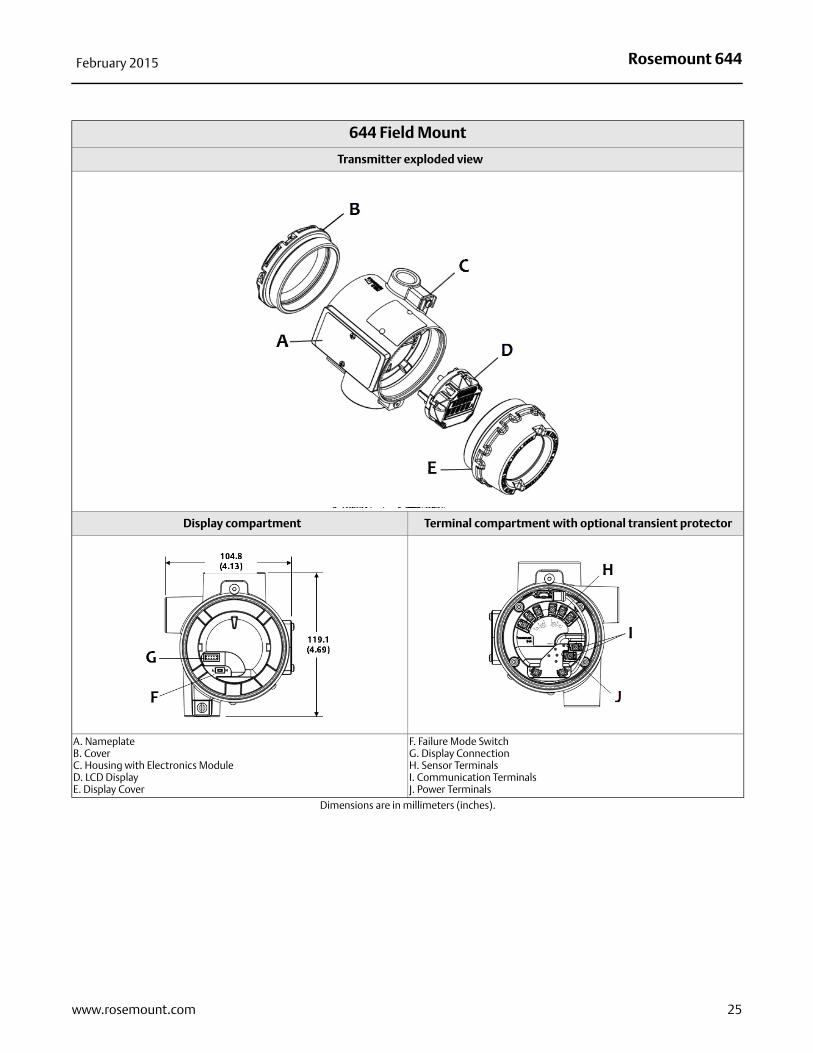
644 Field Mount
Transmitter exploded view
Display compartment Terminal compartment with optional transient protector
A. NameplateB. CoverC. Housing with Electronics ModuleD. LCD DisplayE. Display Cover
F. Failure Mode SwitchG. Display ConnectionH. Sensor TerminalsI. Communication TerminalsJ. Power Terminals
Dimensions are in millimeters (inches).
25www.rosemount.com
Rosemount 644February 2015
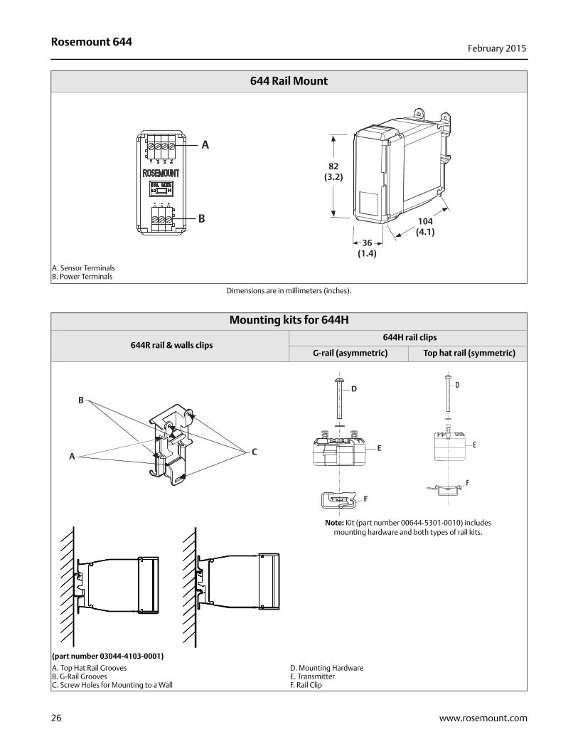
644 Rail Mount
A. Sensor TerminalsB. Power Terminals
Dimensions are in millimeters (inches).
A
B
82(3.2)
104(4.1)
36(1.4)
Mounting kits for 644H
644R rail & walls clips644H rail clips
G-rail (asymmetric) Top hat rail (symmetric)
Note: Kit (part number 00644-5301-0010) includes mounting hardware and both types of rail kits.
(part number 03044-4103-0001)
A. Top Hat Rail GroovesB. G-Rail GroovesC. Screw Holes for Mounting to a Wall
D. Mounting HardwareE. TransmitterF. Rail Clip
A
B
C
D
E
F
D
E
F
26 www.rosemount.com
Rosemount 644February 2015
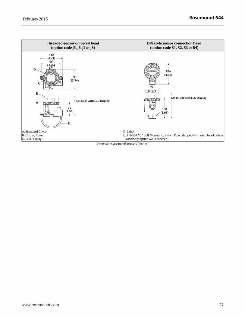
Threaded-sensor universal head (option code J5, J6, J7 or J8)
DIN style sensor connection head (option code R1, R2, R3 or R4)
A. Standard CoverB. Display CoverC. LCD Display
D. LabelE. 316 SST “U” Bolt Mounting, 2-inch Pipe (shipped with each head unless
assembly option XA is ordered)
Dimensions are in millimeters (inches).
A
B
C
D
E
112(4.41)
96(3.76)
95(3.74)
75(2.93)
103 (4.03) with LCD Display
104(4.09)
78 (3.07)
128 (5.04) with LCD Display
100(3.93)
27www.rosemount.com
Rosemount 644February 2015
28 www.rosemount.com
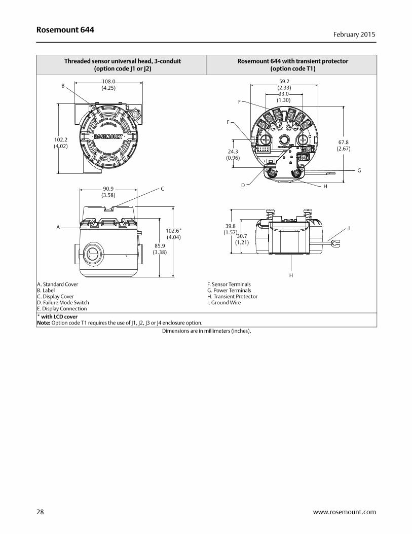
Threaded sensor universal head, 3-conduit(option code J1 or J2)
Rosemount 644 with transient protector (option code T1)
A. Standard CoverB. LabelC. Display CoverD. Failure Mode SwitchE. Display Connection
F. Sensor TerminalsG. Power TerminalsH. Transient ProtectorI. Ground Wire
* with LCD coverNote: Option code T1 requires the use of J1, J2, J3 or J4 enclosure option.
Dimensions are in millimeters (inches).
108.0(4.25)B
102.2(4.02)
90.9(3.58)
85.9(3.38)
102.6*(4.04)
C
A
59.2(2.33)33.0
(1.30)
24.3(0.96)
67.8(2.67)
39.8(1.57)
30.7(1.21)
H
H
G
I
D
F
E
Rosemount 644February 2015
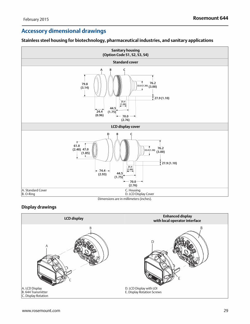
Accessory dimensional drawings
Stainless steel housing for biotechnology, pharmaceutical industries, and sanitary applications
Display drawings
Sanitary housing (Option Code S1, S2, S3, S4)
Standard cover
LCD display cover
A. Standard CoverB. O-Ring
C. HousingD. LCD Display Cover
Dimensions are in millimeters (inches).
A B C
79.8(3.14)
76.2(3.00)
70.0(2.76)
24.4(0.96)
44.5(1.75)
25.4(1.00)
27.9 (1.10)
33.0 (1.30)
D B C
70.0(2.76)
61.0(2.40) 47.0
(1.85)
74.4(2.93)
25.4(1.00)
44.5(1.75)
33.0 (1.30)76.2
(3.00)
27.9 (1.10)
LCD display Enhanced display
with local operator interface
A. LCD DisplayB. 644 TransmitterC. Display Rotation
D. LCD Display with LOIE. Display Rotation Screws
B
A
C
B
D
E
29www.rosemount.com
Rosemount 644February 2015
30 www.rosemount.com
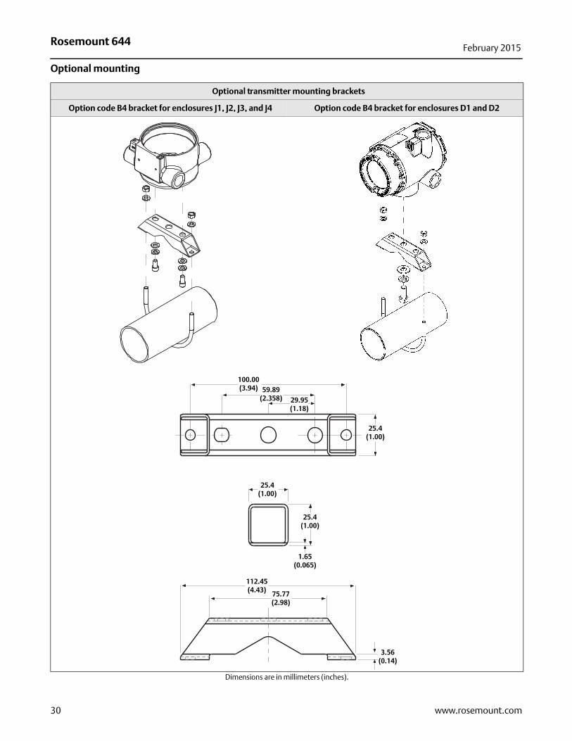
Optional mounting
Optional transmitter mounting brackets
Option code B4 bracket for enclosures J1, J2, J3, and J4 Option code B4 bracket for enclosures D1 and D2
Dimensions are in millimeters (inches).
59.89(2.358) 29.95
(1.18)
25.4(1.00)
100.00(3.94)
25.4(1.00)
25.4(1.00)
1.65(0.065)
112.45(4.43) 75.77
(2.98)
3.56(0.14)
Rosemount 644February 2015
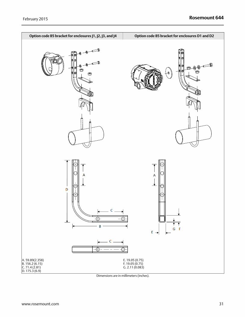
Option code B5 bracket for enclosures J1, J2, J3, and J4 Option code B5 bracket for enclosures D1 and D2
A. 59.89(2.358)B. 156.2 (6.15)C. 71.4 (2.81)D. 175.3 (6.9)
E. 19.05 (0.75)F. 19.05 (0.75)G. 2.11 (0.083)
Dimensions are in millimeters (inches).
31www.rosemount.com
Rosemount 644February 2015
32 www.rosemount.com
Configuration
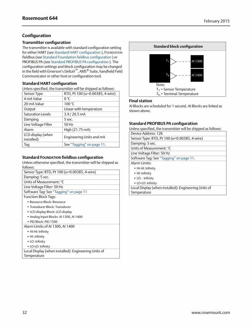
Transmitter configurationThe transmitter is available with standard configuration setting for either HART (see Standard HART configuration ), FOUNDATION fieldbus (see Standard Foundation fieldbus configuration ) or PROFIBUS PA (see Standard PROFIBUS PA configuration ). The configuration settings and block configuration may be changed in the field with Emerson’s DeltaV™, AMS® Suite, handheld Field Communicator or other host or configuration tool.
Standard HART configurationUnless specified, the transmitter will be shipped as follows:
Standard FOUNDATION fieldbus configurationUnless otherwise specified, the transmitter will be shipped as follows:
Final stationAI Blocks are scheduled for 1 second. AI Blocks are linked as shown above.
Standard PROFIBUS PA configurationUnless specified, the transmitter will be shipped as follows:
Sensor Type RTD, Pt 100 (α=0.00385, 4-wire)4 mA Value 0 °C20 mA Value 100 °COutput Linear with temperatureSaturation Levels 3.9 / 20.5 mADamping 5 sec.Line Voltage Filter 50 HzAlarm High (21.75 mA) LCD display (when installed)
Engineering Units and mA
Tag See “Tagging” on page 11.
Sensor Type: RTD, Pt 100 (α=0.00385, 4-wire)Damping: 5 sec.Units of Measurement: °CLine Voltage Filter: 50 HzSoftware Tag: See “Tagging” on page 11 Function Block Tags:
• Resource Block: Resource
• Transducer Block: Transducer
• LCD display Block: LCD display
• Analog Input Blocks: AI 1300, AI 1400
• PID Block: PID 1500Alarm Limits of AI 1300, AI 1400
• HI-HI: Infinity
• HI: Infinity
• LO: Infinity
• LO-LO: InfinityLocal Display (when installed): Engineering Units of Temperature
Standard block configuration
Device Address: 126Sensor Type: RTD, Pt 100 (α=0.00385, 4-wire)Damping: 5 sec.Units of Measurement: °CLine Voltage Filter: 50 HzSoftware Tag: See “Tagging” on page 11.Alarm Limits:
• HI-HI: Infinity
• HI: Infinity
• LO: - Infinity
• LO-LO: InfinityLocal Display (when installed): Engineering Units of Temperature
T1
Tb
Note:T1 = Sensor TemperatureTb = Terminal Temperature
AI 1300
AI 1400
Rosemount 644February 2015
Custom configurationCustom configurations are to be specified when ordering. This configuration must be the same for all sensors. The following table lists the necessary requirements to specify a custom configuration.
Option code Customization available
HA
RT
C1: Factory Configuration Data (CDS required)
Also needs option code:
...DC
...DC
...M4 or M5
Date: day/month/year
Descriptor: 8 alphanumeric characters
Message: 32 alphanumeric characters
Hardware Tag: 13 Characters
Software Tag: 8 Characters
Sensor Type and Connection
Measurement Range and Units
Damping Value
Failure Mode: High or Low
Hot Backup: Mode and PV
Sensor Drift Alert: Mode, Limit and Units
Display Configuration: Choose what will be shown on the LCD display
Custom Alarm and saturation levels: Choose custom High and Low Alarm and Saturation levels
Security information: Write Protection, HART Lock and Local Operator Interface Password
C2:Transmitter – Sensor Matching The transmitters are designed to accept Callendar-Van Dusen constants from a calibrated RTD. Using these constants, the transmitter generates a custom curve to match the sensor-specific curve. Specify a Series 65, 65, or 78 RTD sensor on the order with a special characterization curve (V or X8Q4 option). These constants will be programmed into the transmitter with this option.
A1, CN, or C8: Alarm Level Configuration A1: NAMUR Alarm and Saturation Levels, with High Alarm configured
CN: NAMUR Alarm and Saturation Levels, with Low Alarm configured
C8: Low Alarm (Standard Rosemount Alarm and Saturation Values)
Q4: Three-Point Calibration with Certificate Calibration certificate. Three-Point calibration at 0, 50 and 100% with certificate.
C4: Five-Point Calibration Will include five-point calibration at 0, 25, 50, 75, and 100% analog and digital output points. Use with Calibration Certificate Q4
HR7: HART Revision configuration Your 644 Head mount and Field mount are HART revision selectable. Order the HR7 code to configure your device to operate in HART Revision 7 mode. Your device is also configurable in the field. Refer to the 644 Quick Start Guide or Reference Manual for more instructions.
Long Software Tag: 32 Characters
33www.rosemount.com
Rosemount 644February 2015
Option code Requirements/specification
FOU
ND
ATIO
N fi
eld
bus
C1: Factory Configuration Data (CDS required)
Date: day/month/yearDescriptor: 16 alphanumeric charactersMessage: 32 alphanumeric characters
C2:Transmitter – Sensor Matching
The transmitters are designed to accept Callendar-Van Dusen constants from a calibrated RTD. Using these constants, the transmitter generates a custom curve to match the sensor-specific curve. Specify a Series 65, 65, or 78 RTD sensor on the order with a special characterization curve (V or X8Q4 option). These constants will be programmed into the transmitter with this option.
C4: Five-Point CalibrationWill include five-point calibration at 0, 25, 50, 75, and 100% analog and digital output points. Use with Calibration Certificate Q4.
Q4: Three-Point Calibration with Certificate
Calibration certificate. Three-Point calibration with certificate.
Option code Requirements/specification
PRO
FIB
US
PA
C1: Factory Configuration Data (CDS required)
Date: day/month/yearDescriptor: 16 alphanumeric charactersMessage: 32 alphanumeric characters
C2:Transmitter – Sensor Matching
The transmitters are designed to accept Callendar-Van Dusen constants from a calibrated RTD. Using these constants, the transmitter generates a custom curve to match the sensor-specific curve. Specify a Series 65, or 78 RTD sensor on the order with a special characterization curve (V or X8Q4 option). These constants will be programmed into the transmitter with this option.
C4: Five-Point CalibrationWill include five-point calibration at 0, 25, 50, 75, and 100% analog and digital output points. Use with Calibration Certificate Q4.
Q4: Three-Point Calibration with Certificate
Calibration certificate. Three-Point calibration with certificate.
34 www.rosemount.com
Rosemount 644February 2015
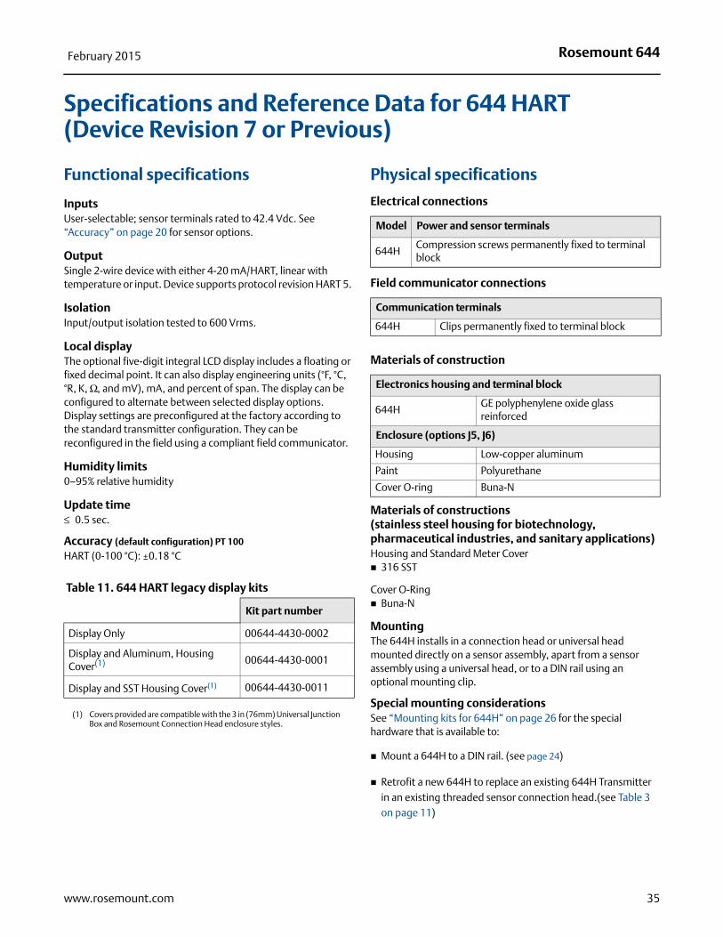
Specifications and Reference Data for 644 HART (Device Revision 7 or Previous)
Functional specifications
InputsUser-selectable; sensor terminals rated to 42.4 Vdc. See “Accuracy” on page 20 for sensor options.
OutputSingle 2-wire device with either 4-20 mA/HART, linear with temperature or input. Device supports protocol revision HART 5.
IsolationInput/output isolation tested to 600 Vrms.
Local display The optional five-digit integral LCD display includes a floating or fixed decimal point. It can also display engineering units (°F, °C, °R, K, Ω, and mV), mA, and percent of span. The display can be configured to alternate between selected display options. Display settings are preconfigured at the factory according to the standard transmitter configuration. They can be reconfigured in the field using a compliant field communicator.
Humidity limits0–95% relative humidity
Update time≤ 0.5 sec.
Accuracy (default configuration) PT 100
HART (0-100 °C): ±0.18 °C
Physical specifications
Electrical connections
Field communicator connections
Materials of construction
Materials of constructions (stainless steel housing for biotechnology, pharmaceutical industries, and sanitary applications)Housing and Standard Meter Cover 316 SST
Cover O-Ring Buna-N
MountingThe 644H installs in a connection head or universal head mounted directly on a sensor assembly, apart from a sensor assembly using a universal head, or to a DIN rail using an optional mounting clip.
Special mounting considerationsSee “Mounting kits for 644H” on page 26 for the special hardware that is available to:
Mount a 644H to a DIN rail. (see page 24)
Retrofit a new 644H to replace an existing 644H Transmitter in an existing threaded sensor connection head.(see Table 3 on page 11)
Table 11. 644 HART legacy display kits
Kit part number
Display Only 00644-4430-0002
Display and Aluminum, Housing Cover(1)
(1) Covers provided are compatible with the 3 in (76mm) Universal Junction Box and Rosemount Connection Head enclosure styles.
00644-4430-0001
Display and SST Housing Cover(1) 00644-4430-0011
Model Power and sensor terminals
644HCompression screws permanently fixed to terminal block
Communication terminals
644H Clips permanently fixed to terminal block
Electronics housing and terminal block
644HGE polyphenylene oxide glass reinforced
Enclosure (options J5, J6)
Housing Low-copper aluminum
Paint Polyurethane
Cover O-ring Buna-N
35www.rosemount.com
Rosemount 644February 2015
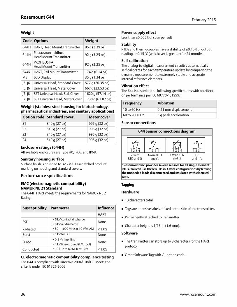
Weight
Weight (stainless steel housing for biotechnology, pharmaceutical industries, and sanitary applications)
Enclosure ratings (644H)All available enclosures are Type 4X, IP66, and IP68.
Sanitary housing surfaceSurface finish is polished to 32 RMA. Laser etched product marking on housing and standard covers.
Performance specifications
EMC (electromagnetic compatibility)NAMUR NE 21 StandardThe 644H HART meets the requirements for NAMUR NE 21 Rating.
CE electromagnetic compatibility compliance testingThe 644 is compliant with Directive 2004/108/EC. Meets the criteria under IEC 61326:2006
Power supply effectLess than ±0.005% of span per volt
StabilityRTDs and thermocouples have a stability of ±0.15% of output reading or 0.15 °C (whichever is greater) for 24 months.
Self calibrationThe analog-to-digital measurement circuitry automatically self-calibrates for each temperature update by comparing the dynamic measurement to extremely stable and accurate internal reference elements.
Vibration effectThe 644 is tested to the following specifications with no effect on performance per IEC 60770-1, 1999:
Sensor connections
Tagging
Hardware
13 characters total
Tags are adhesive labels affixed to the side of the transmitter.
Permanently attached to transmitter
Character height is 1/16-in (1.6 mm).
Software
The transmitter can store up to 8 characters for the HART protocol.
Order Software Tag with C1 option code.
Code Options Weight
644H HART, Head Mount Transmitter 95 g (3.39 oz)
644HFOUNDATION fieldbus, Head Mount Transmitter
92 g (3.25 oz)
644HPROFIBUS PAHead Mount Transmitter
92 g (3.25 oz)
644R HART, Rail Mount Transmitter 174 g (6.14 oz)
M5 LCD Display 35 g (1.34 oz)
J5, J6 Universal Head, Standard Cover 577 g (20.35 oz)
J5, J6 Universal Head, Meter Cover 667 g (23.53 oz)
J7, J8 SST Universal Head, Std. Cover 1620 g (57.14 oz)
J7, J8 SST Universal Head, Meter Cover 1730 g (61.02 oz)
Option code Standard cover Meter cover
S1 840 g (27 oz) 995 g (32 oz)
S2 840 g (27 oz) 995 g (32 oz)
S3 840 g (27 oz) 995 g (32 oz)
S4 840 g (27 oz) 995 g (32 oz)
Susceptibility Parameter Influence
HART
ESD• 6 kV contact discharge
• 8 kV air dischargeNone
Radiated • 80 – 1000 MHz at 10 V/m AM < 1.0%
Burst • 1 kV for I.O. None
Surge• 0.5 kV line–line
• 1 kV line–ground (I.O. tool)None
Conducted • 10 kHz to 80 MHz at 10 V < 1.0%
Frequency Vibration
10 to 60 Hz 0.21 mm displacement
60 to 2000 Hz 3 g peak acceleration
644 Sensor connections diagram
*Rosemount Inc. provides 4-wire sensors for all single element RTDs. You can use these RTDs in 3-wire configurations by leaving the unneeded leads disconnected and insulated with electrical tape.
2-wire RTD and �
3-wire RTD and �
4-wire RTD and �
T/C and mV*
1 2 3 4 1 2 3 4 1 2 3 4 1 2 3 4
36 www.rosemount.com
Rosemount 644February 2015
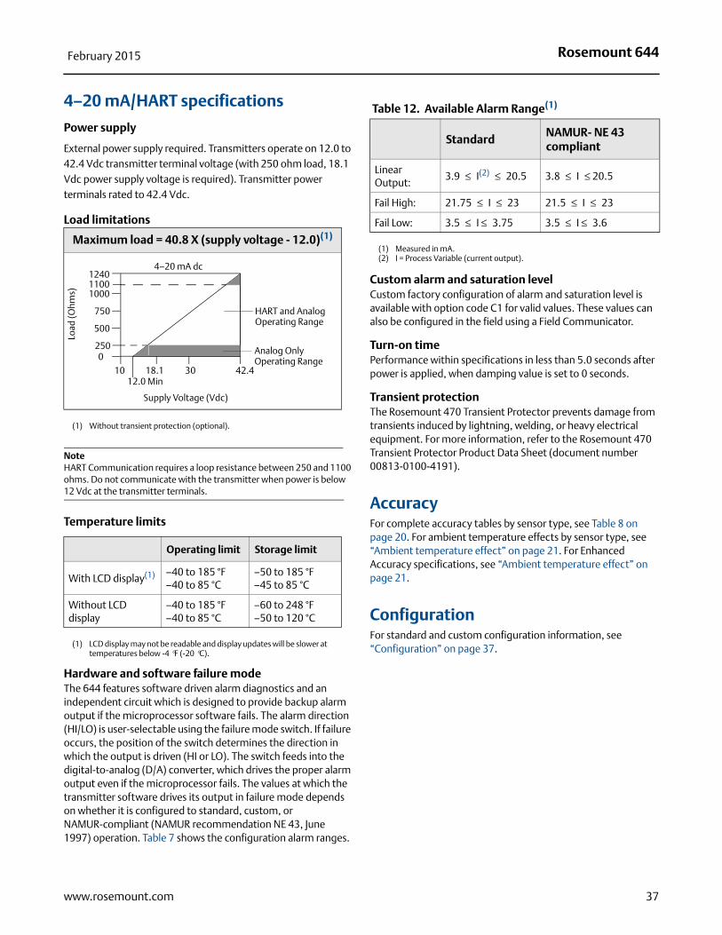
4–20 mA/HART specifications
Power supply
External power supply required. Transmitters operate on 12.0 to 42.4 Vdc transmitter terminal voltage (with 250 ohm load, 18.1 Vdc power supply voltage is required). Transmitter power terminals rated to 42.4 Vdc.
Load limitations
NoteHART Communication requires a loop resistance between 250 and 1100 ohms. Do not communicate with the transmitter when power is below 12 Vdc at the transmitter terminals.
Temperature limits
Hardware and software failure modeThe 644 features software driven alarm diagnostics and an independent circuit which is designed to provide backup alarm output if the microprocessor software fails. The alarm direction (HI/LO) is user-selectable using the failure mode switch. If failure occurs, the position of the switch determines the direction in which the output is driven (HI or LO). The switch feeds into the digital-to-analog (D/A) converter, which drives the proper alarm output even if the microprocessor fails. The values at which the transmitter software drives its output in failure mode depends on whether it is configured to standard, custom, or NAMUR-compliant (NAMUR recommendation NE 43, June 1997) operation. Table 7 shows the configuration alarm ranges.
Custom alarm and saturation levelCustom factory configuration of alarm and saturation level is available with option code C1 for valid values. These values can also be configured in the field using a Field Communicator.
Turn-on timePerformance within specifications in less than 5.0 seconds after power is applied, when damping value is set to 0 seconds.
Transient protectionThe Rosemount 470 Transient Protector prevents damage from transients induced by lightning, welding, or heavy electrical equipment. For more information, refer to the Rosemount 470 Transient Protector Product Data Sheet (document number 00813-0100-4191).
AccuracyFor complete accuracy tables by sensor type, see Table 8 on page 20. For ambient temperature effects by sensor type, see “Ambient temperature effect” on page 21. For Enhanced Accuracy specifications, see “Ambient temperature effect” on page 21.
ConfigurationFor standard and custom configuration information, see “Configuration” on page 37.
Maximum load = 40.8 X (supply voltage - 12.0)(1)
(1) Without transient protection (optional).
Operating limit Storage limit
With LCD display(1)
(1) LCD display may not be readable and display updates will be slower at temperatures below -4 °F (-20 °C).
–40 to 185 °F–40 to 85 °C
–50 to 185 °F–45 to 85 °C
Without LCD display
–40 to 185 °F–40 to 85 °C
–60 to 248 °F–50 to 120 °C
1240
1000
750
2500
1012.0 Min
18.1 30 42.4
Supply Voltage (Vdc)
HART and Analog Operating Range
4–20 mA dc
Load
(Ohm
s)
500
1100
Analog Only Operating Range
Table 12. Available Alarm Range(1)
(1) Measured in mA.
Standard NAMUR- NE 43 compliant
Linear Output:
3.9 ≤ I(2) ≤ 20.5
(2) I = Process Variable (current output).
3.8 ≤ I ≤ 20.5
Fail High: 21.75 ≤ I ≤ 23 21.5 ≤ I ≤ 23
Fail Low: 3.5 ≤ I ≤ 3.75 3.5 ≤ I ≤ 3.6
37www.rosemount.com
Rosemount 644February 2015
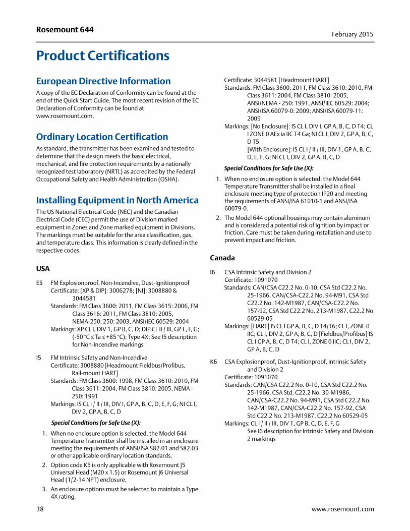
Product Certifications
European Directive InformationA copy of the EC Declaration of Conformity can be found at the end of the Quick Start Guide. The most recent revision of the EC Declaration of Conformity can be found at www.rosemount.com.
Ordinary Location Certification As standard, the transmitter has been examined and tested to determine that the design meets the basic electrical, mechanical, and fire protection requirements by a nationally recognized test laboratory (NRTL) as accredited by the Federal Occupational Safety and Health Administration (OSHA).
Installing Equipment in North America The US National Electrical Code (NEC) and the Canadian Electrical Code (CEC) permit the use of Division marked equipment in Zones and Zone marked equipment in Divisions. The markings must be suitable for the area classification, gas, and temperature class. This information is clearly defined in the respective codes.
USA
E5 FM Explosionproof, Non-Incendive, Dust-IgnitionproofCertificate: [XP & DIP]: 3006278; [NI]: 3008880 &
3044581Standards: FM Class 3600: 2011, FM Class 3615: 2006, FM
Class 3616: 2011, FM Class 3810: 2005, NEMA-250: 250: 2003, ANSI/IEC 60529: 2004
Markings: XP CL I, DIV 1, GP B, C, D; DIP CL II / III, GP E, F, G; (-50 °C ≤ Ta ≤ +85 °C); Type 4X; See I5 description for Non-Incendive markings
I5 FM Intrinsic Safety and Non-IncendiveCertificate: 3008880 [Headmount Fieldbus/Profibus,
Rail-mount HART]Standards: FM Class 3600: 1998, FM Class 3610: 2010, FM
Class 3611: 2004, FM Class 3810: 2005, NEMA - 250: 1991
Markings: IS CL I / II / III, DIV I, GP A, B, C, D, E, F, G; NI CL I, DIV 2, GP A, B, C, D
Special Conditions for Safe Use (X):
1. When no enclosure option is selected, the Model 644 Temperature Transmitter shall be installed in an enclosure meeting the requirements of ANSI/ISA S82.01 and S82.03 or other applicable ordinary location standards.
2. Option code K5 is only applicable with Rosemount J5 Universal Head (M20 x 1.5) or Rosemount J6 Universal Head (1/2-14 NPT) enclosure.
3. An enclosure options must be selected to maintain a Type 4X rating.
Certificate: 3044581 [Headmount HART]Standards: FM Class 3600: 2011, FM Class 3610: 2010, FM
Class 3611: 2004, FM Class 3810: 2005, ANSI/NEMA - 250: 1991, ANSI/IEC 60529: 2004; ANSI/ISA 60079-0: 2009; ANSI/ISA 60079-11: 2009
Markings: [No Enclosure]: IS CL I, DIV I, GP A, B, C, D T4; CL I ZONE 0 AEx ia IIC T4 Ga; NI CL I, DIV 2, GP A, B, C, D T5[With Enclosure]: IS CL I / II / III, DIV 1, GP A, B, C, D, E, F, G; NI CL I, DIV 2, GP A, B, C, D
Special Conditions for Safe Use (X):
1. When no enclosure option is selected, the Model 644 Temperature Transmitter shall be installed in a final enclosure meeting type of protection IP20 and meeting the requirements of ANSI/ISA 61010-1 and ANSI/ISA 60079-0.
2. The Model 644 optional housings may contain aluminum and is considered a potential risk of ignition by impact or friction. Care must be taken during installation and use to prevent impact and friction.
Canada
I6 CSA Intrinsic Safety and Division 2Certificate: 1091070Standards: CAN/CSA C22.2 No. 0-10, CSA Std C22.2 No.
25-1966, CAN/CSA-C22.2 No. 94-M91, CSA Std C22.2 No. 142-M1987, CAN/CSA-C22.2 No. 157-92, CSA Std C22.2 No. 213-M1987, C22.2 No 60529-05
Markings: [HART] IS CL I GP A, B, C, D T4/T6; CL I, ZONE 0 IIC; CL I, DIV 2, GP A, B, C, D [Fieldbus/Profibus] IS CL I GP A, B, C, D T4; CL I, ZONE 0 IIC; CL I, DIV 2, GP A, B, C, D
K6 CSA Explosionproof, Dust-Ignitionproof, Intrinsic Safety and Division 2
Certificate: 1091070Standards: CAN/CSA C22.2 No. 0-10, CSA Std C22.2 No.
25-1966, CSA Std. C22.2 No. 30-M1986, CAN/CSA-C22.2 No. 94-M91, CSA Std C22.2 No. 142-M1987, CAN/CSA-C22.2 No. 157-92, CSA Std C22.2 No. 213-M1987, C22.2 No 60529-05
Markings: CL I / II / III, DIV 1, GP B, C, D, E, F, GSee I6 description for Intrinsic Safety and Division 2 markings
38 www.rosemount.com
Rosemount 644February 2015
Europe
E1 ATEX FlameproofCertificate: FM12ATEX0065XStandards: EN 60079-0: 2012, EN 60079-1: 2007, EN
60529:1991 +A1:2000
Markings: II 2 G Ex d IIC T6…T1 Gb, T6(-50 °C ≤ Ta ≤ +40 °C), T5…T1(-50 °C ≤ Ta ≤ +60 °C)
See Table 13 at the end of the Product Certifications section for Process Temperatures.
Special Conditions for Safe Use (X):
1. See certificate for ambient temperature range.
2. The non-metallic label may store an electrostatic charge and become a source of ignition in Group III environments.
3. Guard the LCD cover against impact energies greater than 4 joules.
4. Consult the manufacturer if dimensional information on the flameproof joints is necessary.
I1 ATEX Intrinsic SafetyCertificate: [Headmount HART]: Baseefa12ATEX0101X
[Headmount Fieldbus/Profibus]: Baseefa03ATEX0499X[Railmount HART]: BAS00ATEX1033X
Standards: EN 60079-0: 2012, EN 60079-11: 2012
Markings: [HART]: II 1 G Ex ia IIC T6…T4 Ga;
[Fieldbus/PROFIBUS]; II 1 G Ex ia IIC T4See Table 14 at the end of the Product Certifications section for Entity Parameters and Temperature Classifications.
Special Condition for Safe Use (X):
1. The equipment must be installed in an enclosure which affords it a degree of protection of at least IP20 in accordance with the requirements of IEC 60529. Non-metallic enclosures must have a surface resistance of less than 1GΩ; light alloy or zirconium enclosures must be protected from impact and friction when installed in a Zone 0 environment.
2. When fitted with the Transient Protector Assembly, the equipment is not capable of withstanding the 500V test as defined in Clause 6.3.13 of EN 60079-11:2012. This must be taken into account during installation.
N1 ATEX Type n - with enclosureCertificate: BAS00ATEX3145Standards: EN 60079-0: 2012, EN 60079-15: 2010
Markings: II 3 G Ex nA IIC T5 Gc (-40 °C ≤ Ta ≤ +70 °C);
NC ATEX Type n - without enclosureCertificate: [Headmount Fieldbus/Profibus, Railmount
HART]: Baseefa13ATEX0093X [Headmount HART]: Baseefa12ATEX0102U
Standards: EN 60079-0: 2012, EN 60079-15: 2010Markings: [Headmount Fieldbus/Profibus, Railmount
HART]: II 3 G Ex nA IIC T5 Gc (-40 °C ≤ Ta ≤ +70 °C)
[Headmount HART]: II 3 G Ex nA IIC T6…T5 Gc; T6(-60 °C ≤ Ta ≤ +40 °C); T5(-60 °C ≤ Ta ≤ +85 °C)
Special Condition for Safe Use (X):
1. The Model 644 Temperature Transmitter must be installed in a suitably certified enclosure such that it is afforded a degree of protection of at least IP54 in accordance with IEC 60529 and EN 60079-15.
2. When fitted with the Transient Protector Assembly, the equipment is not capable of withstanding the 500V test. This must be taken into account during installation.
ND ATEX DustCertificate: FM12ATEX0065XStandards: EN 60079-0: 2012, EN 60079-31: 2009, EN
60529:1991 +A1:2000
Markings: II 2 D Ex tb IIIC T130°C Db, (-40 °C ≤ Ta ≤ +70 °C); IP66
See Table 13 at the end of the Product Certifications section for Process Temperatures.
Special Conditions for Safe Use (X):
1. See certificate for ambient temperature range.
2. The non-metallic label may store an electrostatic charge and become a source of ignition in Group III environments.
3. Guard the LCD cover against impact energies greater than 4 joules.
4. Consult the manufacturer if dimensional information on the flameproof joints is necessary.
International
E7 IECEx Intrinsic SafetyCertificate: IECEx FMG 12.0022XStandards: IEC 60079-0: 2011, IEC 60079-1: 2007Markings: Ex d IIC T6…T1 Gb, T6(-50 °C ≤ Ta ≤ +40 °C),
T5…T1(-50 °C ≤ Ta ≤ +60 °C)See Table 13 at the end of the Product Certifications section for Process Temperatures.
Conditions of Certification (X):
1. See certificate for ambient temperature range.
2. The non-metallic label may store an electrostatic charge and become a source of ignition in Group III environments.
3. Guard the LCD cover against impact energies greater than 4 joules.
4. Consult the manufacturer if dimensional information on the flameproof joints is necessary.
I7 IECEx Intrinsic SafetyCertificate: [Headmount HART]: IECEx BAS 12.0069X
[Headmount Fieldbus/Profibus, Railmount HART]: IECEx BAS 07.0053X
Standards: IEC 60079-0: 2011, IEC 60079-11: 2011Markings: Ex ia IIC T6…T4 GaSee Table 14 at the end of the Product Certifications section for Entity Parameters and Temperature Classifications.
39www.rosemount.com
Rosemount 644February 2015
Conditions of Certification (X):
1. The equipment must be installed in an enclosure which affords it a degree of protection of at least IP20 in accordance with the requirements of IEC 60529. Non-metallic enclosures must have a surface resistance of less than 1GΩ; light alloy or zirconium enclosures must be protected from impact and friction when installed in a Zone 0 environment.
2. When fitted with the Transient Protector Assembly, the equipment is not capable of withstanding the 500V test as defined in Clause 6.3.13 of IEC 60079-11:2011. This must be taken into account during installation.
N7 IECEx Type n - with enclosureCertificate: IECEx BAS 07.0055Standards: IEC 60079-0: 2011, IEC 60079-15: 2010Markings: Ex nA IIC T5 Gc (-40 °C ≤ Ta ≤ +70 °C)
NG IECEx Type n - without enclosureCertificate: [Headmount Fieldbus/Profibus, Railmount
HART]: IECEx BAS 12.0053X [Headmount HART]: IECEx BAS 12.0070U
Standards: IEC 60079-0: 2011, IEC 60079-15: 2010Markings: [Headmount Fieldbus/Profibus, Railmount
HART]: Ex nA IIC T5 Gc (-40 °C ≤ Ta ≤ +70 °C)
Conditions of Certification (X):
1. The Model 644 Temperature Transmitter must be installed in a suitably certified enclosure such that it is afforded a degree of protection of at least IP54 in accordance with IEC 60529 and IEC 60079-15.
2. When fitted with the Transient Protector Assembly, the equipment is not capable of withstanding the 500V test. This must be taken into account during installation.
NK IECEx DustCertificate: IECEx FMG 12.0022XStandards: IEC 60079-0: 2011, IEC 60079-31: 2008Markings: Ex tb IIIC T130°C Db, (-40 °C ≤ Ta ≤ +70 °C); IP66See Table 13 at the end of the Product Certifications section for Process Temperatures
Conditions of Certification (X):
1. See certificate for ambient temperature range.
2. The non-metallic label may store an electrostatic charge and become a source of ignition in Group III environments.
3. Guard the LCD cover against impact energies greater than 4 joules.
4. Consult the manufacturer if dimensional information on the flameproof joints is necessary.
Brazil
E2 INMETRO FlameproofCertificate: NCC 12.1147XStandards: ABNT NBR IEC 60079-0:2008, ABNT NBR IEC 60079-1:2009, NBR 8094:1983Markings: Ex d IIC T6…T1 (-40 °C ≤ Ta ≤ +65 °C) Gb; IP66W
Special Conditions for Safe Use (X):
1. Care must be taken to ensure that the surface temperature does not exceed 85 °C when RTDs or thermocouples are fitted to the transmitter.
2. The mechanical and chemical characteristics of the process fluid must be evaluated in order not to cause deterioration or corrosion to the temperature probes.
3. For information on the dimensions of explosion-proof joints, the manufacturer should be contacted.
I2 INMETRO Intrinsic SafetyCertificate: CEPEL 02.0096XStandards: ABNT NBR IEC 60079-0:2008, ABNT NBR IEC
60079-11:2009, ABNT NBR IEC 60079-26:2008, ABNT NBR IEC 60529:2009
Markings: Ex ia IIC T* Ga; IP66WSee Table 14 at the end of the Product Certifications section for Entity Parameters and Temperature Classifications.
Special Conditions for Safe Use (X):
1. The apparatus must be installed in an enclosure which affords it a degree of protection of at least IP20.
2. Light alloy or zirconium enclosures must be protected from impact and friction when installed.
3. When the maximum ambient temperature at the place of installation is greater than 50 °C, the equipment shall be installed with adequate insulation cables with a minimum rated temperature of 90 °C.
China
E3 China FlameproofCertificate: GYJ111385Standards: GB3836.1-2000, GB3836.2-2000, GB12476.1-2000Markings: Ex d IIC T6; DIP A20 Ta 95 °C; IP66
Special Conditions for Safe Use (X):
1. Temperature Assembly using temperature sensor type 65, 68, 75, 183, 185 are certified.
2. The ambient temperature range is:
3. The earth connection facility in the enclosure should be connected reliably.
Gas/dust Ambient temperature
Gas -40 °C ≤ Ta ≤ +65 °CDust -40 °C ≤ Ta ≤ +85 °C
40 www.rosemount.com
Rosemount 644February 2015
41www.rosemount.com
4. During installation, use and maintenance in explosive gas atmospheres, observe the warning “Do not open when energized”. During installation, use and maintenance in explosive dust atmosphere, observe the warning “Do not open when an explosive dust atmosphere is present”.
5. During installation, there should be no mixture harmful to flameproof housing.
6. During installation in hazardous location, cable glands, conduits and blanking plugs, certified by state-appointed inspection bodies with Ex d IIC, DIP A20 IP66 degree, should be used.
7. Maintenance should be done in a non-hazardous location.
8. During installation, use and maintenance in explosive dust atmosphere, product enclosure should be cleaned to avoid dust accumulation, but compressed air should not be used.
9. End users are not permitted to change any components inside, but to settle the problem in conjunction with manufacturer to avoid damage to the product.
10. During installation, use and maintenance of this product, observe the following standards:GB3836.13-1997 “Electrical apparatus for explosive gas atmospheres Part 13: Repair and overhaul for apparatus used in explosive gas atmospheres”GB3836.15-2000 “Electrical apparatus for explosive gas atmospheres Part 15: Electrical installations in hazardous area (other than mines)”GB3836.16-2006 “Electrical apparatus for explosive gas atmospheres Part 16: Inspection and maintenance of electrical installation (other than mines)”GB50257-1996 “Code for construction and acceptance of electric device for explosion atmospheres and fire hazard electrical equipment installation engineering”.GB15577-1995 “Safe regulation for explosive dust atmospheres”GB12476.2-2006 “Electrical apparatus for use in the presence of combustible dust Part 1-2: Electrical apparatus protected by enclosures and surface temperature limitation-Selection, installation and maintenance”
I3 China Intrinsic SafetyCertificate: GYJ111384XStandards: GB3836.1-2000, GB3836.4-2000Markings: Ex ia IIC T4/T5/T6
Special Conditions for Safe Use (X):1. The ambient temperature range is:
When options do not select Enhanced Performance:
When options select Enhanced Performance:
2. Parameters:
When options do not select Enhanced Performance:
Terminals of power supply (+, -)
Terminals of sensor (1,2,3,4)
When options select Enhanced Performance:
Terminals of power supply (+, -)
Terminals of sensor (1,2,3,4)
3. This product complies to the requirements for FISCO field devices specified in IEC60079-27: 2008. For the connection of an intrinsically safe circuit in accordance FISCO model, FISCO parameters of this product are as above.
4. The product should be used with Ex-certified associated apparatus to establish explosion protection system that can be used in explosive gas atmospheres. Wiring and terminals should comply with the instruction manual of the product and associated apparatus.
Transmitter output
Maximuminput
power: (W)T code Ambient temperature
A
0.67 T6 -60 °C ≤ Ta ≤ +40 °C0.67 T5 -60 °C ≤ Ta ≤ +50 °C
1 T5 -60 °C ≤ Ta ≤ +40 °C1 T4 -60 °C ≤ Ta ≤ +80 °C
F or W1.3 T4 -50 °C ≤ Ta ≤ +60 °C
5.32 T4 -50 °C ≤ Ta ≤ +60 °C
MaximumInput Power: (W)
T code Ambient temperature
0.67 T6 -60 °C ≤ Ta ≤ +40 °C0.67 T5 -60 °C ≤ Ta ≤ +50 °C0.80 T5 -60 °C ≤ Ta ≤ +40 °C0.80 T4 -60 °C ≤ Ta ≤ +80 °C
Transmitter output
Maximuminput
voltage: Ui (V)
Maximuminput
current: Ii (mA)
Maximuminput
power: Pi (W)
Maximuminternal
parameters
Ci (nF) Li (mH)
A 30 200 0.67/1 10 0F, W 30 300 1.3 2.1 0
F, W (FISCO) 17.5 380 5.32 2.1 0
Transmitter output
Maximumoutput
voltage: Uo (V)
Maximumoutput
current: Io (mA)
Maximumoutput
power: Po (W)
Maximuminternal
parameters
Co (nF)Lo
(mH)
A 13.6 80 0.08 75 0
F, W 13.9 23 0.079 7.7 0
Maximuminput
voltage: Ui (V)
Maximuminput current: Ii
(mA)
Maximuminput
power: Pi (W)
Maximuminternal
parameters
Ci (nF) Li (mH)
30
150 (Ta ≤ +80 °C)
0.67/0.8 3.3 0170 (Ta ≤ +70 °C)
190 (Ta ≤ +60 °C)
Maximumoutput
voltage: Uo (V)
Maximumoutput
current: Io (mA)
Maximumoutput
power: Po (W)
Gas group
Maximuminternal parameters
Co (nF) Lo (mH)
13.6 80 0.08
IIC 0.816 5.79
IIB 5.196 23.4
IIA 18.596 48.06
Rosemount 644February 2015
5. The cables between this product and associated apparatus should be shielded cables (the cables must have insulated shield). The shielded has to be grounded reliably in non-hazardous area.
6. End users are not permitted to change any components insides, but to settle the problem in conjunction with manufacturer to avoid damage to the product
7. During installation, use and maintenance of this product, observe the following standards:GB3836.13-1997 “Electrical apparatus for explosive gas atmospheres Part 13: Repair and overhaul for apparatus used in explosive gas atmospheres”GB3836.15-2000 “Electrical apparatus for explosive gas atmospheres Part 15: Electrical installations in hazardous area (other than mines)”GB3836.16-2006 “Electrical apparatus for explosive gas atmospheres Part 16: Inspection and maintenance of electrical installation (other than mines)”GB50257-1996 “Code for construction and acceptance of electric device for explosion atmospheres and fire hazard electrical equipment installation engineering”.
N3 China Type nCertificate: GYJ101421Standards Used: GB3836.1-2000, GB3836.8-2003Markings: Ex nA nL IIC T5/T6
Special Conditions for Safe Use (X):1. The relation among T code, ambient temperature range is
as following:
When options do not select Enhanced Performance:
When options select Enhanced Performance:
2. Maximum input voltage: 42.4V.
3. Cable glands, conduit or blanking plugs, certified by NEPSI with Ex e or Ex n protection type and appropriate thread type and IP54 degree, should be used on external connections and redundant cable entries.
4. Maintenance should be done in non-hazardous location.
5. End users are not permitted to change any components inside, but to settle the problem in conjunction with manufacturer to avoid damage to the product.
6. During installation, use and maintenance of this product, observe the following standards:GB3836.13-1997 “Electrical apparatus for explosive gas atmospheres Part 13: Repair and overhaul for apparatus used in explosive gas atmospheres”GB3836.15-2000 “Electrical apparatus for explosive gas atmospheres Part 15: Electrical installations in hazardous area (other than mines)”GB3836.16-2006 “Electrical apparatus for explosive gas
atmospheres Part 16: Inspection and maintenance of electrical installation (other than mines)”GB50257-1996 “Code for construction and acceptance of electric device for explosion atmospheres and fire hazard electrical equipment installation engineering”
EAC - Belarus, Kazakhstan, Russia
EM Technical Regulation Customs Union (EAC) FlameproofCertificate: RU C-US.GB05.B.00289Standards: GOST R IEC 60079-0-2011, GOST IEC
60079-1-2011Markings: 1Ex d IIC T6…T1 Gb X, T6(-50 °C ≤Ta ≤+40 °C),
T5…T1(-50 °C ≤Ta ≤+60 °C); IP65/IP66/IP68
Special Conditions for Safe Use (X):
1. See certificate for special conditions.
IM Technical Regulation Customs Union (EAC) Intrinsic SafetyCertificate: RU C-US.GB05.B.00289Standards: GOST R IEC 60079-0-2011, GOST R IEC
60079-11-2010Markings: [HART]: 0Ex ia IIC T4…T6 Ga X;
[Fieldbus/Profibus]: 0Ex ia IIC T4 Ga X
Special Conditions for Safe Use (X):
1. See certificate for special conditions.
Japan
E4 Japan FlameproofCertificate: TC20671 [J2 with LCD], TC20672 [J2], TC20673
[J6 with LCD], TC20674 [J6]Markings: Ex d IIC T5
CombinationsK1 Combination of E1, I1, N1, and NDK2 Combination of E2 and I2K5 Combination of E5 and I5K7 Combination of E7, I7, and N7KA Combination of K6, E1, and I1KB Combination of K5 and K6KC Combination of I5 and I6KD Combination of E5, I5, K6, E1, and I1KM Combination of EM, and IM
Additional Certifications
SBS American Bureau of Shipping (ABS) Type ApprovalCertificate: 11-HS771994A-1-PDAABS Rules: 2013 Steel Vessels Rules 1-1-4/7.7,
1-1-Appendix 3, 4-8-3/1.7, 4-8-3/13.1
SBV Bureau Veritas (BV) Type ApprovalCertificate: 26325/A2 BVRequirements: Bureau Veritas Rules for the Classification of
Steel ShipsApplication: Class notations: AUT-UMS, AUT-CCS,
AUT-PORT and AUT-IMS
T code Ambient temperature
T5 -40 °C ≤ Ta ≤ +70 °C
T code Ambient temperature
T6 -60 °C ≤ Ta ≤ +40 °CT5 -60 °C ≤ Ta ≤ +85 °C
42 www.rosemount.com
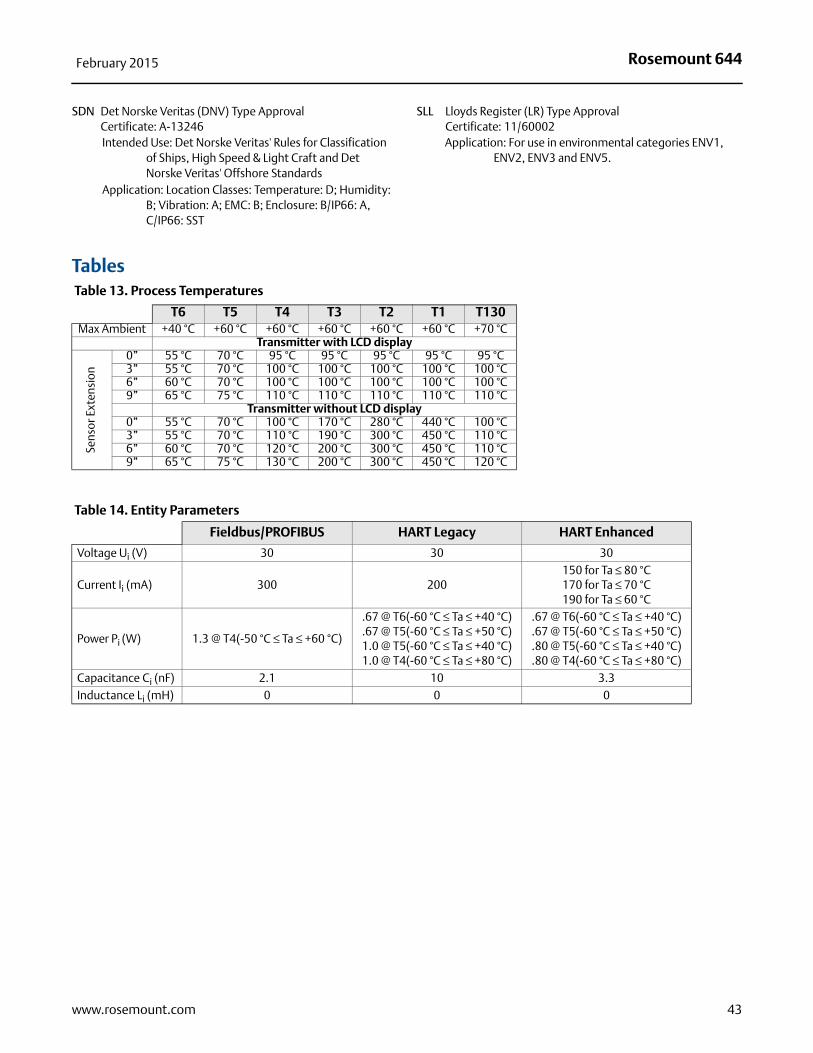
Rosemount 644February 2015
SDN Det Norske Veritas (DNV) Type ApprovalCertificate: A-13246Intended Use: Det Norske Veritas' Rules for Classification
of Ships, High Speed & Light Craft and Det Norske Veritas' Offshore Standards
Application: Location Classes: Temperature: D; Humidity: B; Vibration: A; EMC: B; Enclosure: B/IP66: A, C/IP66: SST
SLL Lloyds Register (LR) Type ApprovalCertificate: 11/60002Application: For use in environmental categories ENV1,
ENV2, ENV3 and ENV5.
Tables Table 13. Process Temperatures
T6 T5 T4 T3 T2 T1 T130Max Ambient +40 °C +60 °C +60 °C +60 °C +60 °C +60 °C +70 °C
Transmitter with LCD display
Sens
or E
xten
sion
0” 55 °C 70 °C 95 °C 95 °C 95 °C 95 °C 95 °C3” 55 °C 70 °C 100 °C 100 °C 100 °C 100 °C 100 °C6” 60 °C 70 °C 100 °C 100 °C 100 °C 100 °C 100 °C9” 65 °C 75 °C 110 °C 110 °C 110 °C 110 °C 110 °C
Transmitter without LCD display0” 55 °C 70 °C 100 °C 170 °C 280 °C 440 °C 100 °C3” 55 °C 70 °C 110 °C 190 °C 300 °C 450 °C 110 °C6” 60 °C 70 °C 120 °C 200 °C 300 °C 450 °C 110 °C9” 65 °C 75 °C 130 °C 200 °C 300 °C 450 °C 120 °C
Table 14. Entity Parameters
Fieldbus/PROFIBUS HART Legacy HART Enhanced
Voltage Ui (V) 30 30 30
Current Ii (mA) 300 200150 for Ta ≤ 80 °C170 for Ta ≤ 70 °C190 for Ta ≤ 60 °C
Power Pi (W) 1.3 @ T4(-50 °C ≤ Ta ≤ +60 °C)
.67 @ T6(-60 °C ≤ Ta ≤ +40 °C)
.67 @ T5(-60 °C ≤ Ta ≤ +50 °C)1.0 @ T5(-60 °C ≤ Ta ≤ +40 °C)1.0 @ T4(-60 °C ≤ Ta ≤ +80 °C)
.67 @ T6(-60 °C ≤ Ta ≤ +40 °C)
.67 @ T5(-60 °C ≤ Ta ≤ +50 °C)
.80 @ T5(-60 °C ≤ Ta ≤ +40 °C)
.80 @ T4(-60 °C ≤ Ta ≤ +80 °C)Capacitance Ci (nF) 2.1 10 3.3Inductance Li (mH) 0 0 0
43www.rosemount.com

Rosemount 64400813-0100-4728 Rev TC
Product Data SheetFebruary 2015
Rosemount World HeadquartersEmerson Process Management 6021 Innovation BlvdShakopee, MN 55379, USA
+1 800 999 9307 or +1 952 906 8888+1 952 949 7001 [email protected]
North America Regional OfficeEmerson Process Management 8200 Market Blvd.Chanhassen, MN 55317, USA
+1 800 999 9307 or +1 952 906 8888+1 952 949 7001 [email protected]
Latin America Regional OfficeEmerson Process Management 1300 Concord Terrace, Suite 400Sunrise, Florida, 33323, USA
+1 954 846 5030+1 954 846 [email protected]
Europe Regional OfficeEmerson Process Management Europe GmbHNeuhofstrasse 19a P.O. Box 1046CH 6340 BaarSwitzerland
+41 (0) 41 768 6111+41 (0) 41 768 6300 [email protected]
Asia Pacific Regional OfficeEmerson Process Management Asia Pacific Pte Ltd1 Pandan CrescentSingapore 128461
+65 6777 8211+65 6777 0947 [email protected]
Middle East and Africa Regional OfficeEmerson Process Management Emerson FZE P.O. Box 17033,Jebel Ali Free Zone - South 2Dubai, United Arab Emirates
+971 4 8118100+971 4 8865465 [email protected]
Standard Terms and Conditions of Sale can be found at www.rose-mount.com\terms_of_sale.The Emerson logo is a trade mark and service mark of Emerson Electric Co.AMS, Rosemount, and the Rosemount logotype are registered trademarks of Rosemount Inc.Hot Backup is a trademark of Rosemount Inc.PlantWeb is a registered trademark of one of the Emerson Process Manage-ment group of companies.DeltaV is a trademark of one of the Emerson Process Management group of companies.HART and WirelessHART are registered trademarks of the HART Communica-tion Foundation.Foundation fieldbus is a trademark of the Fieldbus Foundation.PROFIBUS is a registered trademark of PROFINET International (PI).eurofast and minifast are registered trademarks of TURCK.All other marks are the property of their respective owners.© 2014 Rosemount Inc. All rights reserved.