Embed Size (px)
Citation preview
Quick Start Guide00825-0100-4810, Rev HA
June 2016
00825-0100-4810_RevHA.fm Page 1 Friday, June 17, 2016 3:15 PM
Rosemount™ 405 Compact Primary Element
June 2016Quick Start Guide
00825-0100-4810_RevHA.fm Page 2 Friday, June 17, 2016 3:15 PM
NOTICEThis guide provides basic guidelines for Rosemount 405. It does not provide instructions for configuration, diagnostics, maintenance, service, troubleshooting, Explosion-proof, Flameproof, or intrinsically safe (I.S.) installations. Refer to the Rosemount 405 Reference Manual (document number 00809-0100-4810) for more instruction. This manual is also available electronically on www.rosemount.com.
If the Rosemount 405 was ordered assembled to a Rosemount 3051S Transmitter, the new assembly is the Rosemount 3051SFC Compact Flowmeter. See the following Quick Start Guide for information on configuration and hazardous locations certifications: Rosemount 3051S Series Pressure Transmitter (document number 00825-0100-4801).
If the Rosemount 405 was ordered assembled to a Rosemount 3051S MultiVariable™ Transmitter, the new assembly is the Rosemount 3051SFC Compact Flowmeter. See the following Quick Start Guide for information on configuration and hazardous locations certifications: 3051S MultiVariable Transmitter (document number 00825-0100-4803).
Process leaks may cause harm or result in death.
To avoid process leaks, use only gaskets designed to seal with the corresponding flange and O-rings to seal process connections.
To ensure correct operation download the most current version of the Engineering Assistant software at:
EmersonProcess.com/en-US/brands/rosemount/Pressure/Pressure-Transmitters/MultiVariable-Transmitters/3051S-MultiVariable/engineering-assistant6/Pages/index.aspx.
Contents Primary element location . . . . . . . . . . . . . 3Primary element orientation . . . . . . . . . . 5
Primary element installation . . . . . . . . . 10Product certifications . . . . . . . . . . . . . . . 13
2
Quick Start GuideJune 2016
00825-0100-4810_RevHA.fm Page 3 Friday, June 17, 2016 3:15 PM
3
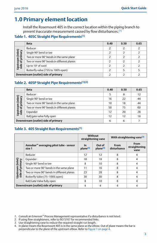
1.0 Primary element locationInstall the Rosemount 405 in the correct location within the piping branch to prevent inaccurate measurement caused by flow disturbances.(1)(2)(3) (4)
1
1. Consult an Emerson™ Process Management representative if a disturbance is not listed.2. If using flow straighteners, refer to ISO 5167 for recommended links.3. Use straightening vane to reduce the required straight run length.4. In plane means the Rosemount 405 is in the same plane as the elbow. Out of plane means the bar is
perpendicular to the plane of the upstream elbow. Refer to Figure 1 on page 4.
Table 1. 405C Straight Pipe Requirements(1)
Beta 0.40 0.50 0.65
Ups
trea
m (i
nlet
) si
de
of p
rim
ary
Reducer 2 2 2
Single 90° bend or tee 2 2 2
Two or more 90° bends in the same plane 2 2 2
Two or more 90° bends in different planes 2 2 2
Up to 10° of swirl 2 2 2
Butterfly valve (75% to 100% open) 2 5 5
Downstream (outlet) side of primary 2 2 2
Table 2. 405P Straight Pipe Requirements(1)(2)
Beta 0.40 0.50 0.65
Ups
trea
m (i
nle
t)
sid
e of
pri
mar
y
Reducer 5 8 12
Single 90° bend or tee 16 22 44
Two or more 90° bends in the same plane 10 18 44
Two or more 90° bends in different planes 50 75 60
Expander 12 20 28
Ball/gate valve fully open 12 12 18
Downstream (outlet) side of primary 6 6 7
Table 3. 405 Straight Run Requirements(1)
Without straightening vane With straightening vane(3)
Annubar™ averaging pitot tube - sensor size 1
In plane(4)
Out of plane(4)
From disturbance
From straightening
vane
Up
stre
am (i
nle
t)
sid
e o
f pri
mar
y
Reducer 12 12 8 4
Expander 18 18 8 4
Single 90° bend or tee 8 10 8 4
Two or more 90° bends in the same plane 11 16 8 4
Two or more 90° bends in different planes 23 28 8 4
Butterfly Valve (75–100% open) 30 30 8 4
Ball/Gate Valve fully open 8 10 8 4
Downstream (outlet) side of primary 4 4 4 4
June 2016Quick Start Guide
00825-0100-4810_RevHA.fm Page 4 Friday, June 17, 2016 3:15 PM
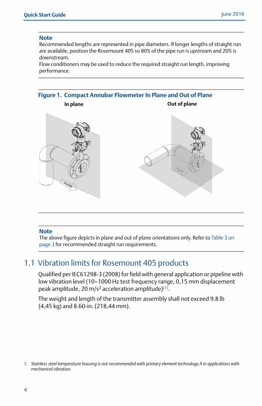
NoteRecommended lengths are represented in pipe diameters. If longer lengths of straight run are available, position the Rosemount 405 so 80% of the pipe run is upstream and 20% is downstream.Flow conditioners may be used to reduce the required straight run length, improving performance.
Figure 1. Compact Annubar Flowmeter In Plane and Out of Plane
NoteThe above figure depicts in plane and out of plane orientations only. Refer to Table 3 on page 3 for recommended straight run requirements.
1.1 Vibration limits for Rosemount 405 productsQualified per IEC61298-3 (2008) for field with general application or pipeline with low vibration level (10–1000 Hz test frequency range, 0,15 mm displacement peak amplitude, 20 m/s2 acceleration amplitude)(1).(1)
The weight and length of the transmitter assembly shall not exceed 9.8 lb (4,45 kg) and 8.60-in. (218,44 mm).
1. Stainless steel temperature housing is not recommended with primary element technology A in applications with mechanical vibration.
FLOWFLOWFLOW
FLOWFLOW
In plane Out of plane
4
Quick Start GuideJune 2016
00825-0100-4810_RevHA.fm Page 5 Friday, June 17, 2016 3:15 PM
5
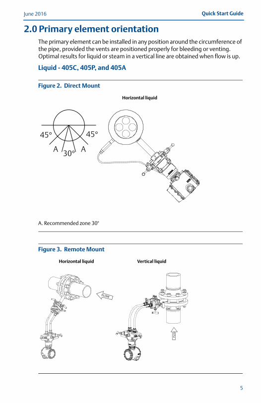
2.0 Primary element orientationThe primary element can be installed in any position around the circumference of the pipe, provided the vents are positioned properly for bleeding or venting. Optimal results for liquid or steam in a vertical line are obtained when flow is up.
Liquid - 405C, 405P, and 405A
Figure 2. Direct Mount
A. Recommended zone 30°
Figure 3. Remote Mount
Horizontal liquid
Horizontal liquid Vertical liquid
45° 45°
30°A A
FLOW
June 2016Quick Start Guide
00825-0100-4810_RevHA.fm Page 6 Friday, June 17, 2016 3:15 PM
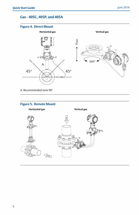
Gas - 405C, 405P, and 405A
Figure 4. Direct Mount
A. Recommended zone 90°
Figure 5. Remote Mount
Horizontal gas Vertical gas
Horizontal gas Vertical gas
45° 45°
A360°
Flow
FLOW
6
Quick Start GuideJune 2016
00825-0100-4810_RevHA.fm Page 7 Friday, June 17, 2016 3:15 PM
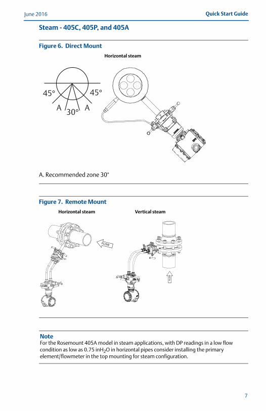
Steam - 405C, 405P, and 405A
Figure 6. Direct Mount
A. Recommended zone 30°
Figure 7. Remote Mount
NoteFor the Rosemount 405A model in steam applications, with DP readings in a low flow condition as low as 0.75 inH2O in horizontal pipes consider installing the primary element/flowmeter in the top mounting for steam configuration.
Horizontal steam
Horizontal steam Vertical steam
45° 45°
30°A A
FLOW
7
June 2016Quick Start Guide
00825-0100-4810_RevHA.fm Page 8 Friday, June 17, 2016 3:15 PM
8
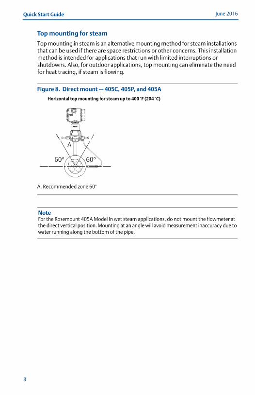
Top mounting for steam
Top mounting in steam is an alternative mounting method for steam installations that can be used if there are space restrictions or other concerns. This installation method is intended for applications that run with limited interruptions or shutdowns. Also, for outdoor applications, top mounting can eliminate the need for heat tracing, if steam is flowing.
Figure 8. Direct mount — 405C, 405P, and 405A
A. Recommended zone 60°
NoteFor the Rosemount 405A Model in wet steam applications, do not mount the flowmeter at the direct vertical position. Mounting at an angle will avoid measurement inaccuracy due to water running along the bottom of the pipe.
Horizontal top mounting for steam up to 400 °F (204 °C)
60° 60°
A
Quick Start GuideJune 2016
00825-0100-4810_RevHA.fm Page 9 Friday, June 17, 2016 3:15 PM
9
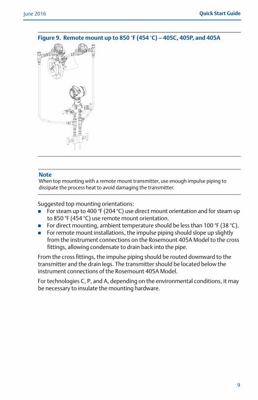
Figure 9. Remote mount up to 850 °F (454 °C) – 405C, 405P, and 405A
NoteWhen top mounting with a remote mount transmitter, use enough impulse piping to dissipate the process heat to avoid damaging the transmitter.
Suggested top mounting orientations: For steam up to 400 °F (204 °C) use direct mount orientation and for steam up
to 850 °F (454 °C) use remote mount orientation. For direct mounting, ambient temperature should be less than 100 °F (38 °C). For remote mount installations, the impulse piping should slope up slightly
from the instrument connections on the Rosemount 405A Model to the cross fittings, allowing condensate to drain back into the pipe.
From the cross fittings, the impulse piping should be routed downward to the transmitter and the drain legs. The transmitter should be located below the instrument connections of the Rosemount 405A Model.
For technologies C, P, and A, depending on the environmental conditions, it may be necessary to insulate the mounting hardware.
June 2016Quick Start Guide
00825-0100-4810_RevHA.fm Page 10 Friday, June 17, 2016 3:15 PM
10
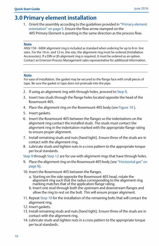
3.0 Primary element installation1. Orient the assembly according to the guidelines provided in “Primary element
orientation” on page 5. Ensure the flow arrow stamped on the 405 Primary Element is pointing in the same direction as the process flow.
NoteANSI 150 - 600# alignment ring is included as standard when ordering for up to 8-in. line sizes. For the 10-in. and 12-in. line size, the alignment ring must be ordered (Installation Accessories). If a DIN or JIS alignment ring is required, it must be ordered as an option. Contact an Emerson Process Management sales representative for additional information.
NoteFor ease of installation, the gasket may be secured to the flange face with small pieces of tape. Be sure the gasket or tape does not protrude into the pipe.
2. If using an alignment ring with through holes, proceed to Step 9.
3. Insert two studs through the flange holes located opposite the head of the Rosemount 405.
4. Place the alignment ring on the Rosemount 405 body (see Figure 10 ).
5. Insert gaskets.
6. Insert the Rosemount 405 between the flanges so the indentations on the alignment ring contact the installed studs. The studs must contact the alignment ring in the indentation marked with the appropriate flange rating to ensure proper alignment.
7. Install remaining studs and nuts (hand tight). Ensure three of the studs are in contact with the alignment ring.
8. Lubricate studs and tighten nuts in a cross pattern to the appropriate torque per local standards.
Step 9 through Step 12 are for use with alignment rings that have through holes.
9. Place the alignment ring on the Rosemount 405 body (see “Horizontal gas” on page 6).
10. Insert the Rosemount 405 between the flanges. a. Starting on the side opposite the Rosemount 405 head, rotate the
alignment ring such that the radius corresponding to the alignment ring marking matches that of the application flange rating.
b. Insert one stud through both the upstream and downstream flanges and allow the ring to rest on the bolt. This will ensure proper alignment.
11. Repeat Step 10 for the installation of the remaining bolts that will contact the alignment ring.
12. Insert gaskets.13. Install remaining studs and nuts (hand tight). Ensure three of the studs are in
contact with the alignment ring.14. Lubricate studs and tighten nuts in a cross pattern to the appropriate torque
per local standards.
Quick Start GuideJune 2016
00825-0100-4810_RevHA.fm Page 11 Friday, June 17, 2016 3:15 PM
11
NoteStandard 1/16-in. gaskets are recommended for use with the Rosemount 405. Using other gaskets could potentially cause a bias shift in the measurement.
3.1 Recommended insulation guidelinesFor flowmeters with integral temperature assembly:
It is recommended that the meter be insulated when the difference between process and ambient temperature is greater than 30 °F (16.6 °C).1. For line sizes 1/2-in. (15 mm) to 4-in. (100 mm), it is recommended to have
4-in. (100 mm) of insulation of at least a 4.35 R-factor.
2. For line sizes 6-in. (150 mm) to 12-in. (300 mm), it is recommended to have 5-in. (125 mm) of insulation of at least a 4.35 R-factor.
The full thickness stated above may not be necessary for the entire flowmeter, but is required for the temperature sensor area at a minimum. Insulation is needed to ensure meeting our specified temperature measurement accuracy. Insulation should only be placed up to the neck and not cover the transmitter.
June 2016Quick Start Guide
00825-0100-4810_RevHA.fm Page 12 Friday, June 17, 2016 3:15 PM
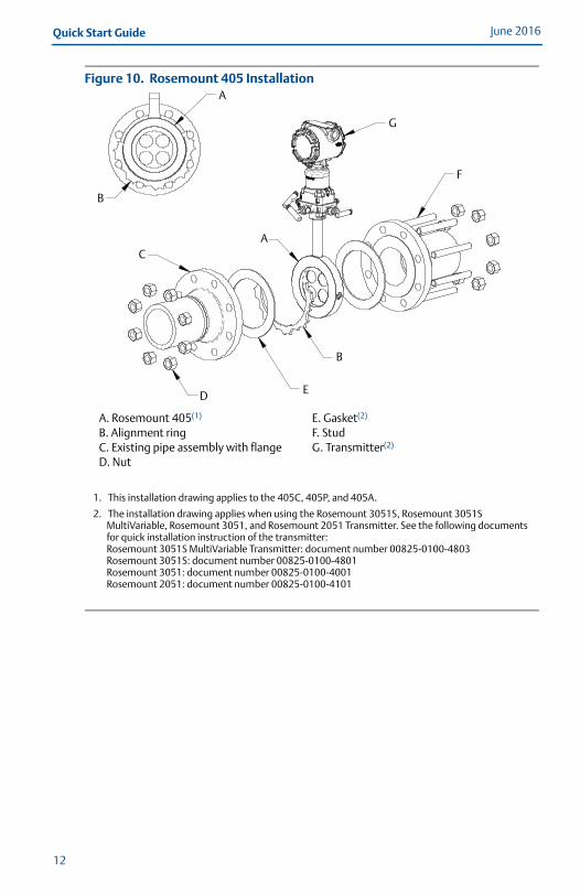
Figure 10. Rosemount 405 Installation
A. Rosemount 405(1) B. Alignment ringC. Existing pipe assembly with flangeD. Nut
1. This installation drawing applies to the 405C, 405P, and 405A.
E. Gasket(2)
F. StudG. Transmitter(2)
2. The installation drawing applies when using the Rosemount 3051S, Rosemount 3051S MultiVariable, Rosemount 3051, and Rosemount 2051 Transmitter. See the following documents for quick installation instruction of the transmitter:Rosemount 3051S MultiVariable Transmitter: document number 00825-0100-4803Rosemount 3051S: document number 00825-0100-4801Rosemount 3051: document number 00825-0100-4001Rosemount 2051: document number 00825-0100-4101
A
B
G
A
F
C
D
B
E
12
Quick Start GuideJune 2016
00825-0100-4810_RevHA.fm Page 13 Friday, June 17, 2016 3:15 PM
4.0 Product certifications
4.1 Approved Manufacturing LocationsRosemount Inc. – Chanhassen, Minnesota USA
Rosemount DP Flow Design and Operations – Boulder, Colorado USA
Emerson Process Management GmbH & Co. OHG – Wessling, Germany
Emerson Process Management Asia Pacific Private Limited – Singapore
Emerson Beijing Instrument Co., Ltd – Beijing, China
4.2 European Directive InformationThe EC declaration of conformity for all applicable European directives for this product can be found on the website at EmersonProcess.com/Rosemount. A hard copy may be obtained by contacting our local sales office.
European Pressure Equipment Directive (PED) (97/23/EC)
Rosemount 405 Compact Primary Element — Sound Engineering Practice (SEP)
Pressure Transmitter — See appropriate Pressure Transmitter QSG.
4.3 Hazardous Locations CertificationsFor information regarding the electronics product certification, see the appropriate transmitter Quick Start Guide: Rosemount 3051SMV: (document number 00825-0100-4803) Rosemount 3051S: (document number 00825-0100-4801) Rosemount 3051: (document number 00825-0100-4001) Rosemount 2051: (document number 00825-0100-4101)
13
June 2016Quick Start Guide
00825-0100-4810_RevHA.fm Page 14 Friday, June 17, 2016 3:15 PM
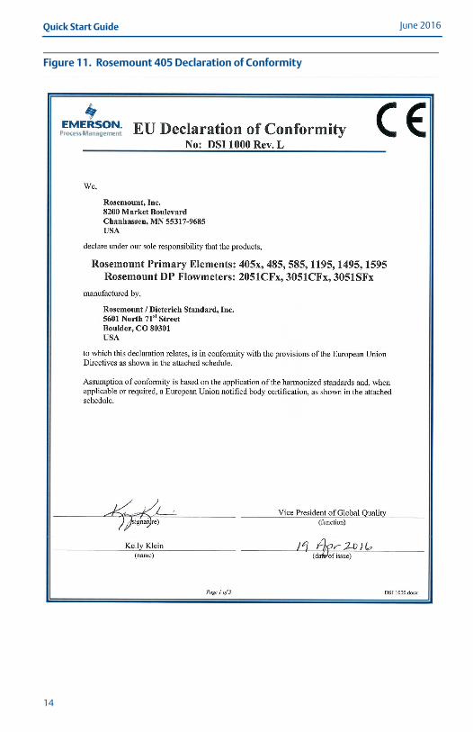
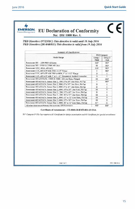
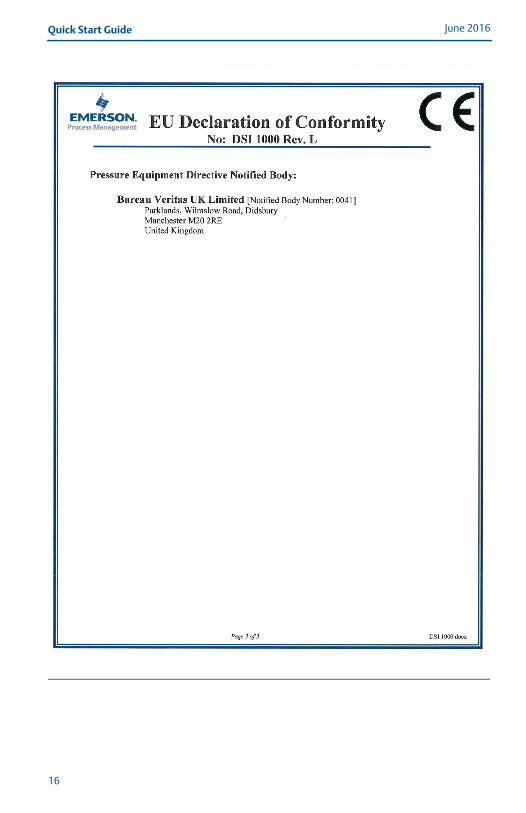
Figure 11. Rosemount 405 Declaration of Conformity
14
Quick Start GuideJune 2016
00825-0100-4810_RevHA.fm Page 15 Friday, June 17, 2016 3:15 PM
15
June 2016Quick Start Guide
00825-0100-4810_RevHA.fm Page 16 Friday, June 17, 2016 3:15 PM
16
Quick Start GuideJune 2016
00825-0100-4810_RevHA.fm Page 17 Friday, June 17, 2016 3:15 PM
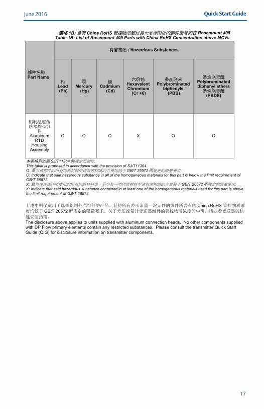
表表格 1B: 含有 China RoHS管控物 超 的部件型号列表 Rosemount 405Table 1B: List of Rosemount 405 Parts with China RoHS Concentration above MCVs
部件名称Part Name
有害物 Hazardous Substances
Lead (Pb)
汞Mercury
(Hg) Cadmium
(Cd)
六价Hexavalent Chromium
(Cr +6)
多Polybrominated
biphenyls (PBB)
多Polybrominated diphenyl ethers 多
(PBDE)
AluminumRTD
Housing Assembly
O O O X O O
本表格系依据 SJ/T11364的This table is proposed in accordance with the provision of SJ/T11364 O:意 GB/T 26572所O: Indicate that said hazardous substance in all of the homogeneous materials for this part is below the limit requirement of GB/T 26572. X:意 GB/T 26572所X: Indicate that said hazardous substance contained in at least one of the homogeneous materials used for this part is above the limit requirement of GB/T 26572.
China RoHS GB/T 26572
The disclosure above applies to units supplied with aluminum connection heads. No other components supplied with DP Flow primary elements contain any restricted substances. Please consult the transmitter Quick Start Guide (QIG) for disclosure information on transmitter components.
17

00825-0100-4810_RevHA.fm Page 18 Friday, June 17, 2016 3:15 PM
Global HeadquartersEmerson Process Management 6021 Innovation Blvd.Shakopee, MN 55379, USA
+1 800 999 9307 or +1 952 906 8888+1 952 949 7001 [email protected]
North America Regional OfficeEmerson Process Management 8200 Market Blvd.Chanhassen, MN 55317, USA
+1 800 999 9307 or +1 952 906 8888
+1 952 949 7001
Latin America Regional OfficeEmerson Process Management 1300 Concord Terrace, Suite 400Sunrise, FL 33323, USA
+1 954 846 5030
+1 954 846 5121
[email protected]/company/Emerson-Process-Management
Twitter.com/Rosemount_News
Facebook.com/Rosemount
Youtube.com/user/RosemountMeasurement
Google.com/+RosemountMeasurement
Standard Terms and Conditions of Sale can be found at www.Emerson.com/en-us/pages/Terms-of-Use.aspxThe Emerson logo is a trademark and service mark of Emerson Electric Co.Annubar, Rosemount and Rosemount logotype are trademarks of Emerson Process Management.All other marks are the property of their respective owners.© 2016 Emerson Process Management. All rights reserved.
Europe Regional OfficeEmerson Process Management Europe GmbHNeuhofstrasse 19a P.O. Box 1046CH 6340 BaarSwitzerland
+41 (0) 41 768 6111
+41 (0) 41 768 6300
Asia Pacific Regional OfficeEmerson Process Management Asia Pacific Pte Ltd1 Pandan CrescentSingapore 128461
+65 6777 8211
+65 6777 0947 [email protected]
Middle East and Africa Regional OfficeEmerson Process Management Emerson FZE P.O. Box 17033,Jebel Ali Free Zone - South 2Dubai, United Arab Emirates
+971 4 8118100
+971 4 [email protected]
Quick Start Guide00825-0100-4810, Rev HA
June 2016
*00825-0100-4810*