Embed Size (px)
Citation preview
www.rosemount.com
¢00825-0100-4028g¤
Quick Installation Guide00825-0100-4028, Rev AAMarch 2005 Pak-Lok 285 Annubar
Step 1: Location and OrientationStep 2: Drill Holes into PipeStep 3: Weld Mounting HardwareStep 4: Insert the AnnubarStep 5: Mount the TransmitterProduct Certifications
Start
End
Rosemount 285 Annubar® Pak-Lok Assembly
00825-0100-4028_Rev AA.fm Page 1 Friday, March 25, 2005 8:33 AM
Quick Installation Guide00825-0100-4028, Rev AA
March 2005Pak-Lok 285 Annubar
2
© 2005 Rosemount Inc. All rights reserved. All marks property of owner. Rosemount and the Rosemount logotype are registered trademarks of Rosemount Inc.
Rosemount Inc.8200 Market BoulevardChanhassen, MN USA 55317T (US) (800) 999-9307T (Intnl) (952) 906-8888F (952) 949-7001
Emerson Process Management GmbH & Co. OHGArgelsrieder Feld 382234 WesslingGermanyT 49 (8153) 9390F49 (8153) 939172
Emerson Process Management Asia Pacific Private Limited1 Pandan CrescentSingapore 128461T (65) 6777 8211F (65) 6777 0947/65 6777 0743
Beijing Rosemount Far East Instrument Co., LimitedNo. 6 North Street, Hepingli, Dong Cheng DistrictBeijing 100013, ChinaT (86) (10) 6428 2233F (86) (10) 6422 8586
IMPORTANT NOTICEThis installation guide provides basic guidelines for Rosemount 285 Annubar. It does not provide instructions for configuration, diagnostics, maintenance, service, troubleshooting, Explosion-proof, Flame-Proof, or instrinsically safe (I.S.) installations. Refer to the 285 Annubar reference manual (document number 00809-0100-4028) for more instruction. This manual is also available electronically on www.rosemount.com.
WARNINGProcess leaks may cause harm or result in death. To avoid process leaks, only use gaskets designed to seal with the corresponding flange and o-rings to seal process connections. Flowing medium may cause the 285 Annubar assembly to become hot and could result in burns.
00825-0100-4028_Rev AA.fm Page 2 Friday, March 25, 2005 8:33 AM
Quick Installation Guide00825-0100-4028, Rev AAMarch 2005 Pak-Lok 285 Annubar
3
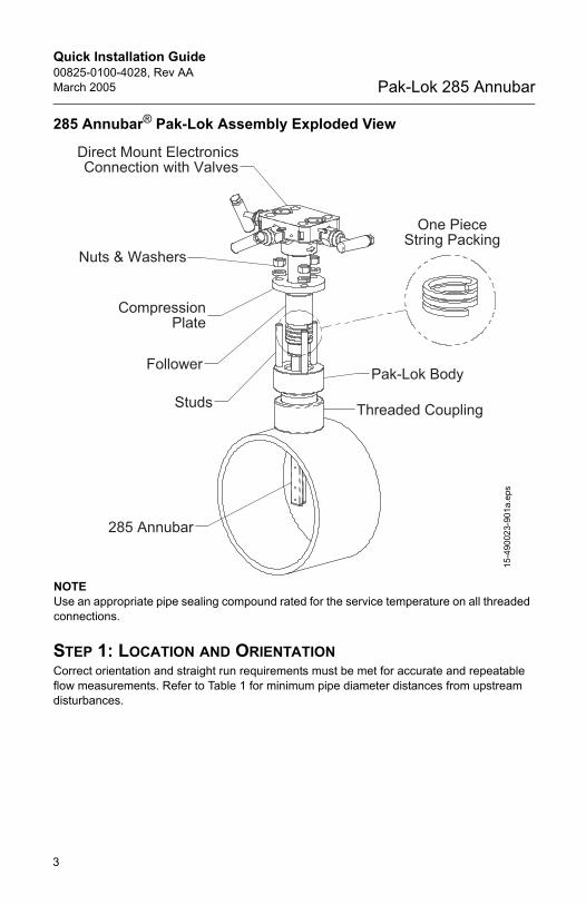
285 Annubar® Pak-Lok Assembly Exploded View
NOTEUse an appropriate pipe sealing compound rated for the service temperature on all threaded connections.
STEP 1: LOCATION AND ORIENTATIONCorrect orientation and straight run requirements must be met for accurate and repeatable flow measurements. Refer to Table 1 for minimum pipe diameter distances from upstream disturbances.
One PieceString Packing
Threaded Coupling
Pak-Lok BodyFollower
Studs
CompressionPlate
Nuts & Washers
Direct Mount ElectronicsConnection with Valves
285 Annubar15
-490
023-
901a
.eps
00825-0100-4028_Rev AA.fm Page 3 Friday, March 25, 2005 8:33 AM
Quick Installation Guide00825-0100-4028, Rev AA
March 2005Pak-Lok 285 Annubar
4
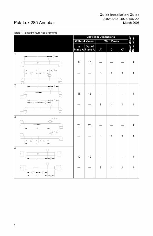
Table 1. Straight Run Requirements Upstream Dimensions
Dow
nstr
eam
Dim
ensi
ons
Without Vanes With Vanes
In Plane A
Out of Plane A A’ C C’
1
8
—
10
—
—
8
—
4
—
4
4
4
2
11
—
16
—
—
8
—
4
—
4
4
4
3
23
—
28
—
—
8
—
4
—
4
4
4
4
12
—
12
—
—
8
—
4
—
4
4
4
00825-0100-4028_Rev AA.fm Page 4 Friday, March 25, 2005 8:33 AM
Quick Installation Guide00825-0100-4028, Rev AAMarch 2005 Pak-Lok 285 Annubar
5
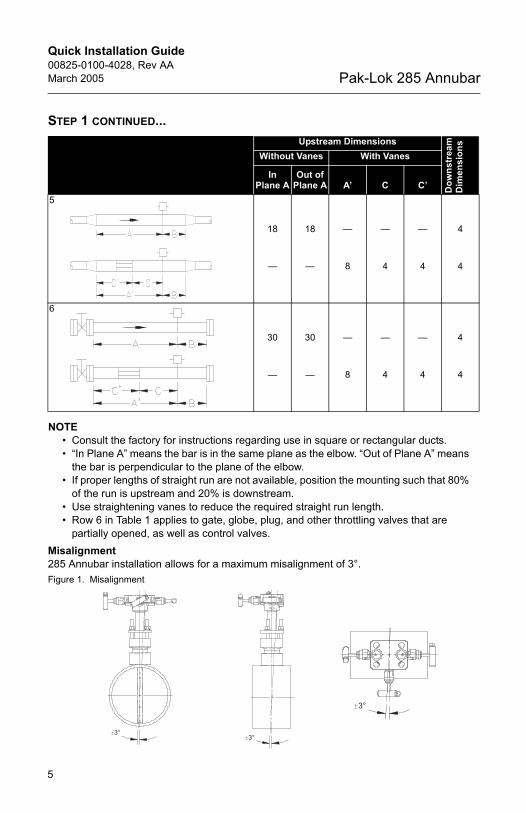
STEP 1 CONTINUED...
NOTE• Consult the factory for instructions regarding use in square or rectangular ducts.• “In Plane A” means the bar is in the same plane as the elbow. “Out of Plane A” means
the bar is perpendicular to the plane of the elbow.• If proper lengths of straight run are not available, position the mounting such that 80%
of the run is upstream and 20% is downstream.• Use straightening vanes to reduce the required straight run length. • Row 6 in Table 1 applies to gate, globe, plug, and other throttling valves that are
partially opened, as well as control valves.Misalignment285 Annubar installation allows for a maximum misalignment of 3°.Figure 1. Misalignment
Upstream Dimensions
Dow
nstr
eam
Dim
ensi
ons
Without Vanes With Vanes
In Plane A
Out of Plane A A’ C C’
5
18
—
18
—
—
8
—
4
—
4
4
4
6
30
—
30
—
—
8
—
4
—
4
4
4
3°
3°
3°
00825-0100-4028_Rev AA.fm Page 5 Friday, March 25, 2005 8:33 AM
Quick Installation Guide00825-0100-4028, Rev AA
March 2005Pak-Lok 285 Annubar
6
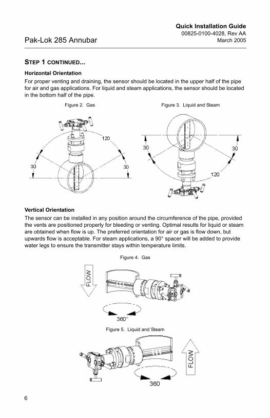
STEP 1 CONTINUED...Horizontal OrientationFor proper venting and draining, the sensor should be located in the upper half of the pipe for air and gas applications. For liquid and steam applications, the sensor should be located in the bottom half of the pipe.
Vertical Orientation The sensor can be installed in any position around the circumference of the pipe, provided the vents are positioned properly for bleeding or venting. Optimal results for liquid or steam are obtained when flow is up. The preferred orientation for air or gas is flow down, but upwards flow is acceptable. For steam applications, a 90° spacer will be added to provide water legs to ensure the transmitter stays within temperature limits.
Figure 2. Gas Figure 3. Liquid and Steam
Figure 4. Gas
Figure 5. Liquid and Steam
00825-0100-4028_Rev AA.fm Page 6 Friday, March 25, 2005 8:33 AM
Quick Installation Guide00825-0100-4028, Rev AAMarch 2005 Pak-Lok 285 Annubar
7
STEP 2: DRILL HOLES INTO PIPE1. Determine the sensor size based on the probe width (see Table 2).2. Depressurize and drain the pipe.3. Select the location to drill the hole. 4. Determine the diameter of the hole to be drilled according to the specifications in Table 2.
Drill the mounting hole into the pipe with a hole saw or drill. DO NOT TORCH CUT THE HOLE.
Table 2. Sensor Size / Hole Diameter Chart
5. Deburr the drilled holes on the inside of the pipe.
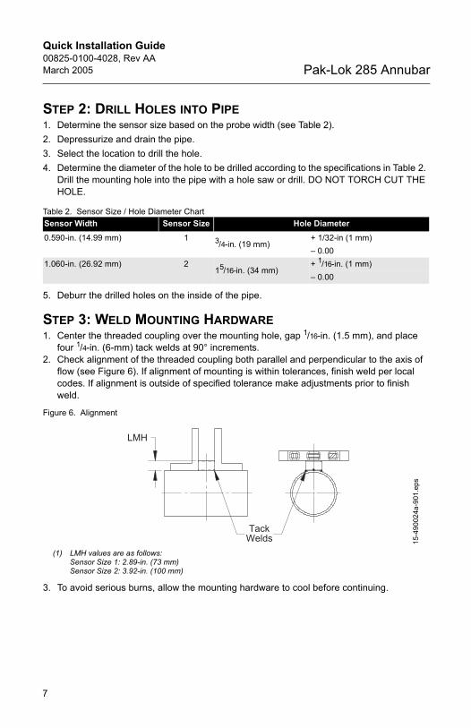
STEP 3: WELD MOUNTING HARDWARE1. Center the threaded coupling over the mounting hole, gap 1/16-in. (1.5 mm), and place
four 1/4-in. (6-mm) tack welds at 90° increments. 2. Check alignment of the threaded coupling both parallel and perpendicular to the axis of
flow (see Figure 6). If alignment of mounting is within tolerances, finish weld per local codes. If alignment is outside of specified tolerance make adjustments prior to finish weld.
Figure 6. Alignment
3. To avoid serious burns, allow the mounting hardware to cool before continuing.
Sensor Width Sensor Size Hole Diameter0.590-in. (14.99 mm) 1 3/4-in. (19 mm)
+ 1/32-in (1 mm)– 0.00
1.060-in. (26.92 mm) 215/16-in. (34 mm)
+ 1/16-in. (1 mm)– 0.00
(1) LMH values are as follows:Sensor Size 1: 2.89-in. (73 mm)Sensor Size 2: 3.92-in. (100 mm)
TackWelds
LMH
15-4
9002
4a-9
01.e
ps
00825-0100-4028_Rev AA.fm Page 7 Friday, March 25, 2005 8:33 AM
Quick Installation Guide00825-0100-4028, Rev AA
March 2005Pak-Lok 285 Annubar
8
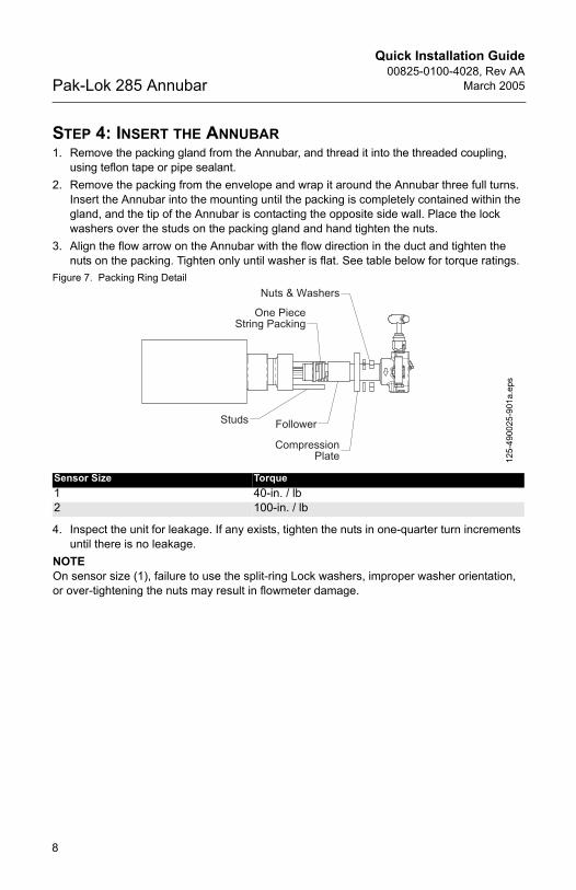
STEP 4: INSERT THE ANNUBAR1. Remove the packing gland from the Annubar, and thread it into the threaded coupling,
using teflon tape or pipe sealant.2. Remove the packing from the envelope and wrap it around the Annubar three full turns.
Insert the Annubar into the mounting until the packing is completely contained within the gland, and the tip of the Annubar is contacting the opposite side wall. Place the lock washers over the studs on the packing gland and hand tighten the nuts.
3. Align the flow arrow on the Annubar with the flow direction in the duct and tighten the nuts on the packing. Tighten only until washer is flat. See table below for torque ratings.
Figure 7. Packing Ring Detail
4. Inspect the unit for leakage. If any exists, tighten the nuts in one-quarter turn increments until there is no leakage.
NOTEOn sensor size (1), failure to use the split-ring Lock washers, improper washer orientation, or over-tightening the nuts may result in flowmeter damage.
Sensor Size Torque1 40-in. / lb2 100-in. / lb
Follower
Nuts & Washers
Compression
Studs
Plate
One PieceString Packing
125-
4900
25-9
01a.
eps
00825-0100-4028_Rev AA.fm Page 8 Friday, March 25, 2005 8:33 AM
Quick Installation Guide00825-0100-4028, Rev AAMarch 2005 Pak-Lok 285 Annubar
9
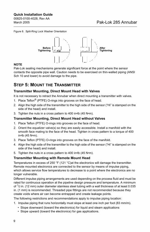
Figure 8. Split-Ring Lock Washer Orientation
NOTEPak-Lok sealing mechanisms generate significant force at the point where the sensor contacts the opposite pipe wall. Caution needs to be exercised on thin-walled piping (ANSI Sch 10 and lower) to avoid damage to the pipe.
STEP 5: MOUNT THE TRANSMITTERTransmitter Mounting, Direct Mount Head with ValvesIt is not necessary to retract the Annubar when direct mounting a transmitter with valves.1. Place Teflon® (PTFE) O-rings into grooves on the face of head.2. Align the high side of the transmitter to the high side of the sensor (“Hi” is stamped on the
side of the head) and install.3. Tighten the nuts in a cross pattern to 400 in•lb (45 N•m).
Transmitter Mounting, Direct Mount Head without Valves1. Place Teflon (PTFE) O-rings into grooves on the face of head.2. Orient the equalizer valve(s) so they are easily accessible. Install a manifold with the
smooth face mating to the face of the head. Tighten in cross pattern to a torque of 400 in•lb (45 N•m).
3. Place Teflon (PTFE) O-rings into grooves on the face of the manifold.4. Align the high side of the transmitter to the high side of the sensor (“Hi” is stamped on the
side of the head) and install.5. Tighten the nuts in a cross pattern to 400 in•lb (45 N•m).
Transmitter Mounting with Remote Mount HeadTemperatures in excess of 250 °F (121 °C)at the electronics will damage the transmitter. Remote mounted electronics are connected to the sensor by means of impulse piping, which allows service flow temperatures to decrease to a point where the electronics are no longer vulnerable.Different impulse piping arrangements are used depending on the process fluid and must be rated for continuous operation at the pipeline design pressure and temperature. A minimum of 1/2 in. (12 mm) outer diameter stainless steel tubing with a wall thickness of at least 0.035 in. (1 mm) is recommended. Threaded pipe fittings are not recommended because they create voids where air can become entrapped and create leakage points. The following restrictions and recommendations apply to impulse piping location:1. Impulse piping that runs horizontally must slope at least one inch per foot (83 mm/m).
• Slope downward (toward the electronics) for liquid and steam applications• Slope upward (toward the electronics) for gas applications.
BeforeTightening
After Tightening
00825-0100-4028_Rev AA.fm Page 9 Friday, March 25, 2005 8:33 AM
Quick Installation Guide00825-0100-4028, Rev AA
March 2005Pak-Lok 285 Annubar
10
2. For applications with temperature below 250 °F (121 °C), impulse piping should be as short as possible to minimize temperature changes. Insulation may be required.
3. For applications above 250 °F (121 °C), impulse piping should have a minimum length of one foot (0.3048 m) for every 100 °F (38°C) temperature increase over 250 °F (121 °C). Impulse piping must be non-insulated to reduce fluid temperature. Any threaded connections should be checked after the system reaches the intended temperature because connections may come loose with contraction and expansion caused by temperature change.
4. Outdoor installations for liquid, saturated gas, or steam may require insulation and heat tracing to prevent freezing.
5. When impulse piping is longer than six feet (1.8 m) the high and low impulse lines must be positioned together to maintain equal temperature. They must be supported to prevent sagging and vibration.
6. Impulse lines should be positioned in protected areas or against walls or ceilings. Use appropriate pipe sealing compound rated for the service temperature on all threaded connections. Do not place the impulse piping near high temperature piping or equipment.
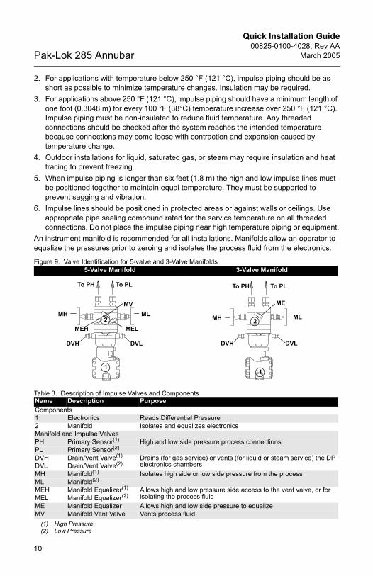
An instrument manifold is recommended for all installations. Manifolds allow an operator to equalize the pressures prior to zeroing and isolates the process fluid from the electronics.
Figure 9. Valve Identification for 5-valve and 3-Valve Manifolds
Table 3. Description of Impulse Valves and Components
5-Valve Manifold 3-Valve Manifold
Name Description PurposeComponents1 Electronics Reads Differential Pressure 2 Manifold Isolates and equalizes electronicsManifold and Impulse ValvesPH Primary Sensor(1)
(1) High Pressure
High and low side pressure process connections.PL Primary Sensor(2)
(2) Low Pressure
DVH Drain/Vent Valve(1) Drains (for gas service) or vents (for liquid or steam service) the DP electronics chambersDVL Drain/Vent Valve(2)
MH Manifold(1) Isolates high side or low side pressure from the processML Manifold(2) MEH Manifold Equalizer(1) Allows high and low pressure side access to the vent valve, or for
isolating the process fluidMEL Manifold Equalizer(2) ME Manifold Equalizer Allows high and low side pressure to equalizeMV Manifold Vent Valve Vents process fluid
To PH To PL
MHMV
ML
DVLDVH
MELMEH2
1
To PH To PL
MH
ME
ML
DVLDVH
2
1
00825-0100-4028_Rev AA.fm Page 10 Friday, March 25, 2005 8:33 AM
Quick Installation Guide00825-0100-4028, Rev AAMarch 2005 Pak-Lok 285 Annubar
11
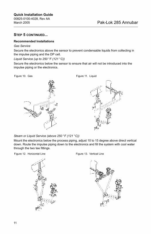
STEP 5 CONTINUED...Recommended InstallationsGas Service Secure the electronics above the sensor to prevent condensable liquids from collecting in the impulse piping and the DP cell.Liquid Service (up to 250 °F (121 °C))Secure the electronics below the sensor to ensure that air will not be introduced into the impulse piping or the electronics.
Steam or Liquid Service (above 250 °F (121 °C))Mount the electronics below the process piping, adjust 10 to 15 degree above direct vertical down. Route the impulse piping down to the electronics and fill the system with cool water through the two tee fittings.
Figure 10. Gas Figure 11. Liquid
Figure 12. Horizontal Line Figure 13. Vertical Line
00825-0100-4028_Rev AA.fm Page 11 Friday, March 25, 2005 8:33 AM

Quick Installation Guide00825-0100-4028, Rev AA
March 2005Pak-Lok 285 Annubar
12
PRODUCT CERTIFICATIONSApproved Manufacturing LocationsRosemount Inc. — Chanhassen, Minnesota USA
European Directive InformationThe EC declaration of conformity for all applicable European directives for this product can be found on the Rosemount website at www.rosemount.com. A hard copy may be obtained by contacting our local sales office.European Pressure Equipment Directive (PED) (97/23/EC)
Rosemount 285 Annubar — Refer to EC declaration of conformity for conformity assessmentPressure Transmitter — See appropriate Pressure Transmitter QIG
00825-0100-4028_Rev AA.fm Page 12 Friday, March 25, 2005 8:33 AM