Embed Size (px)
Citation preview
www.rosemount.com
¢00825-0100-4832ª¤
Quick Installation Guide00825-0100-4832, Rev BAOctober 2009 Rosemount 3095FC
MODBUS®
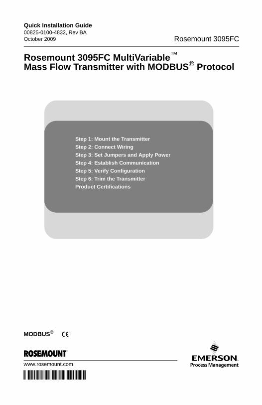
Step 1: Mount the Transmitter
Step 2: Connect Wiring
Step 3: Set Jumpers and Apply Power
Step 4: Establish Communication
Step 5: Verify Configuration
Step 6: Trim the Transmitter
Product Certifications
Rosemount 3095FC MultiVariable™ Mass Flow Transmitter with MODBUS® Protocol
Quick Installation Guide00825-0100-4832, Rev BA
October 2009Rosemount 3095FC
© 2009 Rosemount Inc. All rights reserved. All marks property of owner. Rosemount and the Rosemount logotype are registered trademarks of Rosemount Inc.
Rosemount Inc.8200 Market BoulevardChanhassen, MN USA 55317T (US) (800) 999-9307, F (952) 949-7001T (Intnl) (952) 906-8888
Emerson Process Management GmbH & Co. OHGArgelsrieder Feld 382234 WesslingGermanyT 49 (8153) 9390, F49 (8153) 939172
Emerson Process Management Asia Pacific Private Limited1 Pandan CrescentSingapore 128461T (65) 6777 8211, F (65) 6777 0947/(65) 6777 0743
Beijing Rosemount Far East Instrument Co., LimitedNo. 6 North Street, Hepingli, Dong Cheng DistrictBeijing 100013, ChinaT (86) (10) 6428 2233, F (86) (10) 6422 8586
IMPORTANT NOTICE
This installation guide provides basic guidelines for the Rosemount 3095FC MultiVariable Mass Flow Transmitter with MODBUS protocol (reference manual 00809-0100-4832). It does not provide instructions for configuration, diagnostics, maintenance, service, or troubleshooting. Refer to the appropriate reference manual for more instruction. The manuals are also available electronically on www.rosemount.com.
WARNING
Explosions could result in death or serious injury:
Installation of this transmitter in an explosive environment must be in accordance with the appropriate local, national, and international standards, codes, and practices.
• Before connecting communications in an explosive atmosphere, make sure the instruments in the loop are installed in accordance with intrinsically safe or non-incendive field wiring practices.
• In an Explosion-Proof/Flame-Proof installation, do not remove the transmitter covers when power is applied to the unit.
Process leaks may cause harm or result in death.• To avoid process leaks, only use the o-ring designed to seal with the corresponding
flange adapter.
Electrical shock can result in death or serious injury.• Avoid contact with the leads and the terminals. High voltage that may be present on
leads can cause electrical shock.
2
Quick Installation Guide00825-0100-4832, Rev BAOctober 2009 Rosemount 3095FC
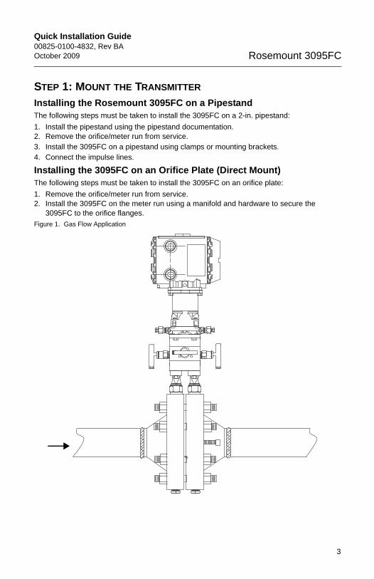
STEP 1: MOUNT THE TRANSMITTER
Installing the Rosemount 3095FC on a PipestandThe following steps must be taken to install the 3095FC on a 2-in. pipestand:
1. Install the pipestand using the pipestand documentation.2. Remove the orifice/meter run from service.3. Install the 3095FC on a pipestand using clamps or mounting brackets.4. Connect the impulse lines.
Installing the 3095FC on an Orifice Plate (Direct Mount)The following steps must be taken to install the 3095FC on an orifice plate:
1. Remove the orifice/meter run from service.2. Install the 3095FC on the meter run using a manifold and hardware to secure the
3095FC to the orifice flanges.
Figure 1. Gas Flow Application
3
Quick Installation Guide00825-0100-4832, Rev BA
October 2009Rosemount 3095FC
STEP 1 CONTINUED...
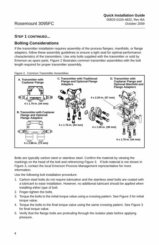
Bolting ConsiderationsIf the transmitter installation requires assembly of the process flanges, manifolds, or flange adapters, follow these assembly guidelines to ensure a tight seal for optimal performance characteristics of the transmitters. Use only bolts supplied with the transmitter or sold by Emerson as spare parts. Figure 2 illustrates common transmitter assemblies with the bolt length required for proper transmitter assembly.
Figure 2. Common Transmitter Assemblies
Bolts are typically carbon steel or stainless steel. Confirm the material by viewing the markings on the head of the bolt and referencing Figure 3. If bolt material is not shown in Figure 3, contact the local Emerson Process Management representative for more information.
Use the following bolt installation procedure:
1. Carbon steel bolts do not require lubrication and the stainless steel bolts are coated with a lubricant to ease installation. However, no additional lubricant should be applied when installing either type of bolt.
2. Finger-tighten the bolts.3. Torque the bolts to the initial torque value using a crossing pattern. See Figure 3 for initial
torque value.4. Torque the bolts to the final torque value using the same crossing pattern. See Figure 3
for final torque value.5. Verify that the flange bolts are protruding through the isolator plate before applying
pressure.
4 x 1.75-in. (44 mm)
4 x 2.88-in. (73 mm)
A. Transmitter with Coplanar Flange
B. Transmitter with Coplanar Flange and Optional Flange Adapters
C. Transmitter with Traditional Flange and Optional Flange Adapters
D. Transmitter with Coplanar Flange and Optional Manifold and Flange Adapters
4 x 1.75-in. (44 mm)4 x 1.50-in. (38 mm)
4 x 1.75-in. (44 mm)
4 x 2.25-in. (57 mm)
4
Quick Installation Guide00825-0100-4832, Rev BAOctober 2009 Rosemount 3095FC
5
STEP 1 CONTINUED...
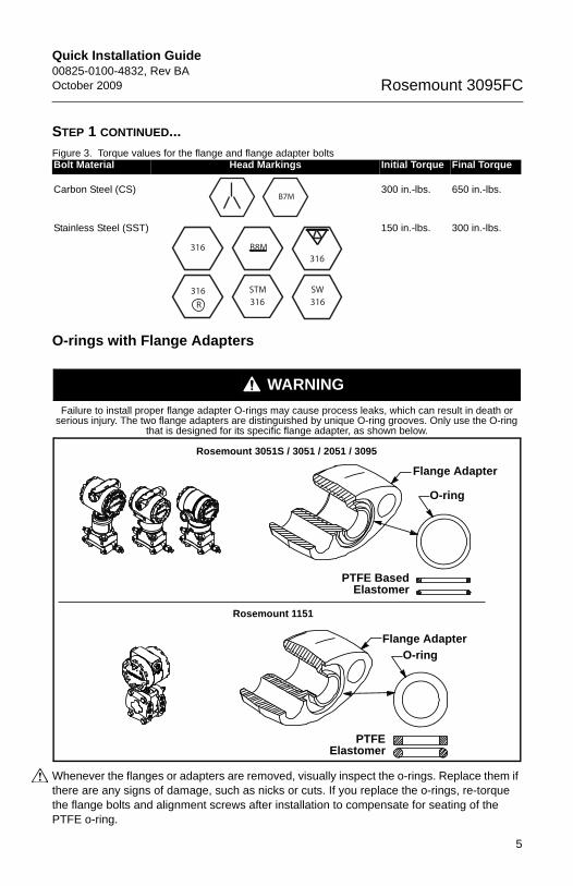
Figure 3. Torque values for the flange and flange adapter bolts
O-rings with Flange Adapters
WARNING
Whenever the flanges or adapters are removed, visually inspect the o-rings. Replace them if there are any signs of damage, such as nicks or cuts. If you replace the o-rings, re-torque the flange bolts and alignment screws after installation to compensate for seating of the PTFE o-ring.
Bolt Material Head Markings Initial Torque Final Torque
Carbon Steel (CS) 300 in.-lbs. 650 in.-lbs.
Stainless Steel (SST) 150 in.-lbs. 300 in.-lbs.
Failure to install proper flange adapter O-rings may cause process leaks, which can result in death or serious injury. The two flange adapters are distinguished by unique O-ring grooves. Only use the O-ring
that is designed for its specific flange adapter, as shown below.
B7M
316316
316SW
316STM316
R
B8M
Rosemount 3051S / 3051 / 2051 / 3095
Rosemount 1151
Flange Adapter
O-ring
Flange Adapter
O-ring
PTFE BasedElastomer
PTFEElastomer
Quick Installation Guide00825-0100-4832, Rev BA
October 2009Rosemount 3095FC
STEP 2: CONNECT WIRINGUse the following steps to wire the transmitter:
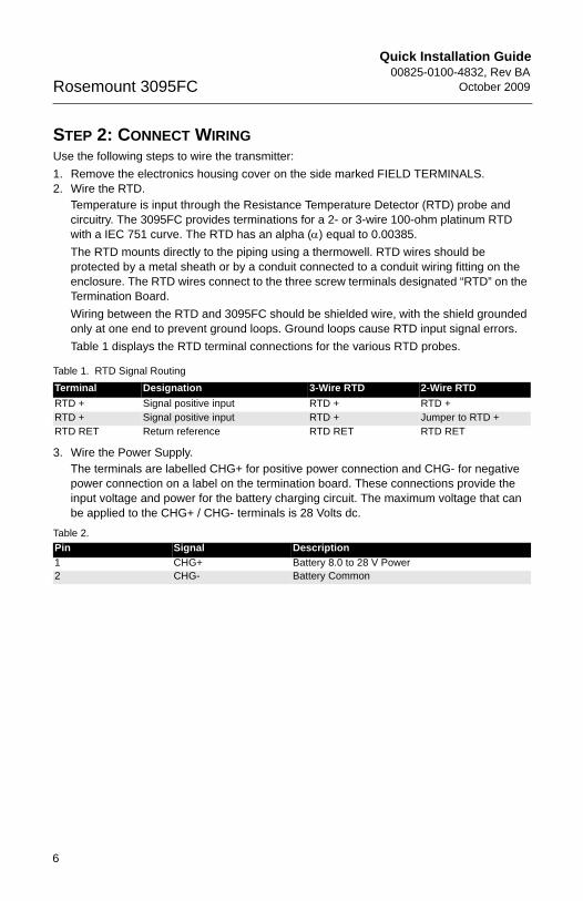
1. Remove the electronics housing cover on the side marked FIELD TERMINALS.2. Wire the RTD.
Temperature is input through the Resistance Temperature Detector (RTD) probe and circuitry. The 3095FC provides terminations for a 2- or 3-wire 100-ohm platinum RTD with a IEC 751 curve. The RTD has an alpha () equal to 0.00385.
The RTD mounts directly to the piping using a thermowell. RTD wires should be protected by a metal sheath or by a conduit connected to a conduit wiring fitting on the enclosure. The RTD wires connect to the three screw terminals designated “RTD” on the Termination Board.
Wiring between the RTD and 3095FC should be shielded wire, with the shield grounded only at one end to prevent ground loops. Ground loops cause RTD input signal errors.
Table 1 displays the RTD terminal connections for the various RTD probes.
Table 1. RTD Signal Routing
3. Wire the Power Supply.The terminals are labelled CHG+ for positive power connection and CHG- for negative power connection on a label on the termination board. These connections provide the input voltage and power for the battery charging circuit. The maximum voltage that can be applied to the CHG+ / CHG- terminals is 28 Volts dc.
Terminal Designation 3-Wire RTD 2-Wire RTD
RTD + Signal positive input RTD + RTD +RTD + Signal positive input RTD + Jumper to RTD +RTD RET Return reference RTD RET RTD RET
Table 2.
Pin Signal Description
1 CHG+ Battery 8.0 to 28 V Power2 CHG- Battery Common
6
Quick Installation Guide00825-0100-4832, Rev BAOctober 2009 Rosemount 3095FC
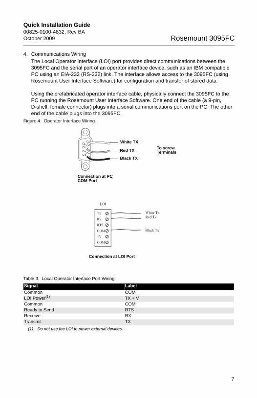
4. Communications WiringThe Local Operator Interface (LOI) port provides direct communications between the 3095FC and the serial port of an operator interface device, such as an IBM compatible PC using an EIA-232 (RS-232) link. The interface allows access to the 3095FC (using Rosemount User Interface Software) for configuration and transfer of stored data.
Using the prefabricated operator interface cable, physically connect the 3095FC to the PC running the Rosemount User Interface Software. One end of the cable (a 9-pin, D-shell, female connector) plugs into a serial communications port on the PC. The other end of the cable plugs into the 3095FC.
Figure 4. Operator Interface Wiring
Table 3. Local Operator Interface Port Wiring
Signal Label
Common COMLOI Power(1)
(1) Do not use the LOI to power external devices.
TX + VCommon COMReady to Send RTSReceive RXTransmit TX
16
7
8
9
2
3
4
5
To screw Terminals
Connection at PC COM Port
White TX
Red TX
Black TX
Connection at LOI Port
7
Quick Installation Guide00825-0100-4832, Rev BA
October 2009Rosemount 3095FC
Figure 5. 3095FC terminal block and wiring diagram
STEP 3: SET JUMPERS AND APPLY POWERTo prevent unnecessary battery drainage, the 3095FC is delivered with the reset jumper in the OFF position. To apply power to the 3095FC:
1. Complete the necessary wiring.2. Unscrew the front end cap cover (LCD end).3. Place the power jumper in the ON position. The jumper is located on the LCD (if
installed) or at J1 on the Battery Charger Board.4. Screw the front-end cap cover (LCD end).
After the 3095FC completes start-up diagnostics (RAM and other internal checks), the optional LCD displays the date and time to indicate that the
3095FC completed a valid reset sequence.
STEP 4: ESTABLISH COMMUNICATION
1. Open the 3095FC User Interface Software2. Enter the factory-assigned User ID and Password:
User ID: LOIPassword: 1000
3. Click Direct Connect, located on the software toolbar.
2 OR 3 WIRE RTD
RTD
LOI
OPERATOR
INTERFACE
CABLE
PC
POWER
SUPPLY
+
+
-
+
RET
CHG
8
Quick Installation Guide00825-0100-4832, Rev BAOctober 2009 Rosemount 3095FC
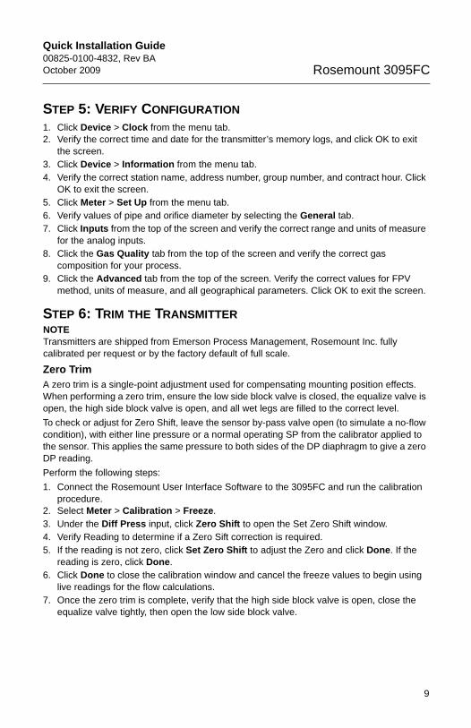
STEP 5: VERIFY CONFIGURATION
1. Click Device > Clock from the menu tab.2. Verify the correct time and date for the transmitter’s memory logs, and click OK to exit
the screen.3. Click Device > Information from the menu tab.4. Verify the correct station name, address number, group number, and contract hour. Click
OK to exit the screen.5. Click Meter > Set Up from the menu tab.6. Verify values of pipe and orifice diameter by selecting the General tab.7. Click Inputs from the top of the screen and verify the correct range and units of measure
for the analog inputs.8. Click the Gas Quality tab from the top of the screen and verify the correct gas
composition for your process.9. Click the Advanced tab from the top of the screen. Verify the correct values for FPV
method, units of measure, and all geographical parameters. Click OK to exit the screen.
STEP 6: TRIM THE TRANSMITTERNOTETransmitters are shipped from Emerson Process Management, Rosemount Inc. fully calibrated per request or by the factory default of full scale.
Zero TrimA zero trim is a single-point adjustment used for compensating mounting position effects. When performing a zero trim, ensure the low side block valve is closed, the equalize valve is open, the high side block valve is open, and all wet legs are filled to the correct level.
To check or adjust for Zero Shift, leave the sensor by-pass valve open (to simulate a no-flow condition), with either line pressure or a normal operating SP from the calibrator applied to the sensor. This applies the same pressure to both sides of the DP diaphragm to give a zero DP reading.
Perform the following steps:
1. Connect the Rosemount User Interface Software to the 3095FC and run the calibration procedure.
2. Select Meter > Calibration > Freeze.3. Under the Diff Press input, click Zero Shift to open the Set Zero Shift window.4. Verify Reading to determine if a Zero Sift correction is required.5. If the reading is not zero, click Set Zero Shift to adjust the Zero and click Done. If the
reading is zero, click Done.6. Click Done to close the calibration window and cancel the freeze values to begin using
live readings for the flow calculations.7. Once the zero trim is complete, verify that the high side block valve is open, close the
equalize valve tightly, then open the low side block valve.
9

Quick Installation Guide00825-0100-4832, Rev BA
October 2009Rosemount 3095FC
PRODUCT CERTIFICATIONS
Approved Manufacturing LocationsRosemount Inc. — Chanhassen, Minnesota USA
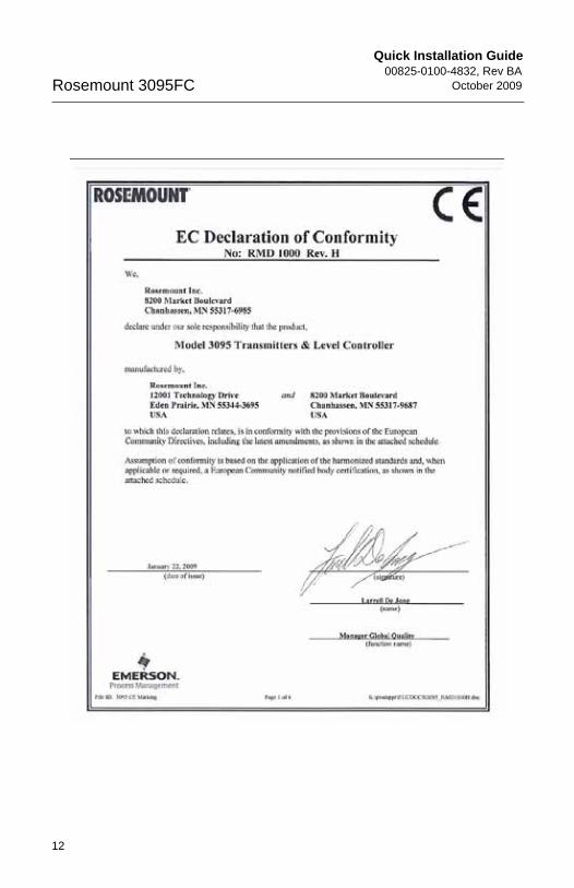
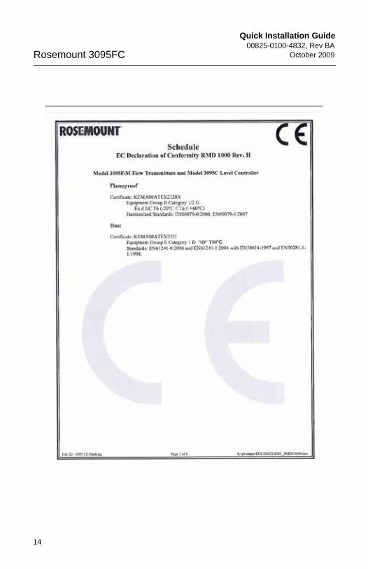
European Directive InformationThe EC declaration of conformity for all applicable European directives for this product can be found on the Rosemount website at www.rosemount.com. A hard copy may be obtained by contacting our local sales office.
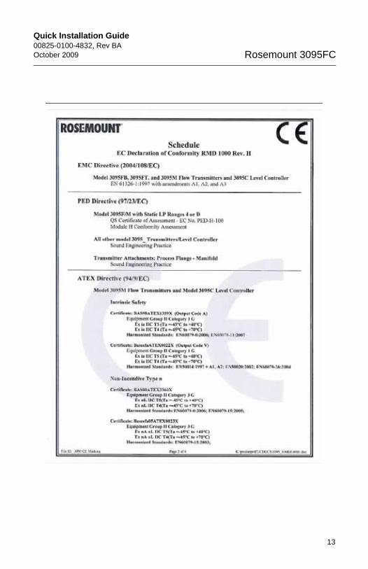
ATEX Directive (94/9/EC)Emerson Process Management complies with the ATEX Directive.
European Pressure Equipment Directive (PED) (97/23/EC)3095F_2/3,4/D Flow Transmitters
— QS Certificate of Assessment - EC No. PED-H-100 Module H Conformity Assessment
All other 3095_ Transmitters/Level Controller
— Sound Engineering Practice
Transmitter Attachments: Process Flange - Manifold
— Sound Engineering Practice
Electro Magnetic Compatibility (EMC) (2004/108/EC)3095F Flow Transmitters - EN 61326-1:1997 - A1, A2, and A3
Ordinary Location Certification for Factory MutualAs standard, the Rosemount 3095FB transmitter has been examined and tested to determine that the design meets basic electrical, mechanical, and fire protection requirements by FM, a nationally recognized testing laboratory (NRTL) as accredited by the Federal Occupational Safety and Health Administration (OSHA).
10
Quick Installation Guide00825-0100-4832, Rev BAOctober 2009 Rosemount 3095FC
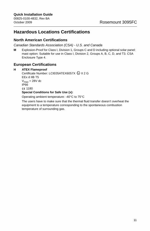
Hazardous Locations Certifications
North American CertificationsCanadian Standards Association (CSA) - U.S. and CanadaM Explosion-Proof for Class I, Division 1, Groups C and D including optional solar panel:
mast option: Suitable for use in Class I, Division 2, Groups A, B, C, D, and T3. CSA Enclosure Type 4.
European CertificationsH ATEX Flameproof
Certificate Number: LCIE05ATEX6057X II 2 GEEx d IIB T5 Vmax = 28V dcIP66
1180Special Conditions for Safe Use (x):
Operating ambient temperature: -40°C to 75°C
The users have to make sure that the thermal fluid transfer doesn’t overheat the equipment to a temperature corresponding to the spontaneous combustion temperature of surrounding gas.
11
Quick Installation Guide00825-0100-4832, Rev BA
October 2009Rosemount 3095FC
12
Quick Installation Guide00825-0100-4832, Rev BAOctober 2009 Rosemount 3095FC
13
Quick Installation Guide00825-0100-4832, Rev BA
October 2009Rosemount 3095FC
14

Quick Installation Guide00825-0100-4832, Rev BAOctober 2009 Rosemount 3095FC
15

Quick Installation Guide00825-0100-4832, Rev BA
October 2009Rosemount 3095FC
16