Embed Size (px)
Citation preview

Product Data SheetJune 2013
00813-0800-4485, Rev EC
Rosemount 1195 Integral Orifice Primary Element
Improves accuracy and repeatability
Self-centering plate design eliminates installation errors that are magnified in small line sizes
Precision honed pipe sections allow accuracy of up to ±0.75% of flow rate
Installation flexibility with numerous process connections
Integral thermowell enables fully compensated mass flow

Rosemount DP Flow June 2013
Contents
Ordering Information
Rosemount 1195 Integral Orifice Primary Element .. . . . . . . . . . . . . . . . . . . . . . . . . . . . . . . . . . . . . . . . . . . . page 4
Rosemount 1195 specifications . . . . . . . . . . . . . . . . . . . . . . . . . . . . . . . . . . . . . . . . . . . . . . . . . . . . . . . . . . . . . . . . . . . . . . . page 8
Rosemount 1195 dimensional drawings . . . . . . . . . . . . . . . . . . . . . . . . . . . . . . . . . . . . . . . . . . . . . . . . . . . . . . . . . . . . . .page 11
Installation and Flowmeter Orientation . . . . . . . . . . . . . . . . . . . . . . . . . . . . . . . . . . . . . . . . . . . . . . . . . . . . . . . . . . . . . Click Here
2 www.rosemount.com

Rosemount DP FlowJune 2013
3www.rosemount.com

Rosemount DP Flow June 2013
Rosemount 1195 Integral Orifice Primary Element
Rosemount 1195 Integral Orifice Primary Element utilizes a self centering orifice plate design to eliminate installation error.
Enables highly accurate flow measurement in small line sizes
Available with a variety of process connections
Available in 1/2 to 11/2-in. (15 - 40 mm) line sizes
Additional InformationSpecifications: page 8Dimensional Drawings: page 11Installation and Flowmeter Orientation: Click Here
1195 Integral Orifice Primary Element
Table 1. Rosemount 1195 Integral Orifice Primary Element Ordering Information★ The Standard offering represents the most common options. The starred options (★) should be selected for best delivery.__The Expanded offering is subject to additional delivery lead time.
Model Product Description
1195 Integral Orifice Primary Flow Element
Body Material
Standard Standard
S 316 SST ★
Line Size
Standard Standard
005 1/2-in. (15 mm) ★
010 1-in. (25 mm) ★
015 11/2-in. (40 mm) ★
Process Connection
Standard Standard
T1 NPT Female Body (not available with thermowell and RTD) ★
S1(1) Socket Weld Body (not available with thermowell and RTD) ★
P1 Pipe Ends: NPT threaded ★
P2 Pipe Ends: Beveled ★
D1 Pipe Ends: Flanged, RF, DIN PN16, slip-on ★
D2 Pipe Ends: Flanged, RF, DIN PN40, slip-on ★
D3 Pipe Ends: Flanged, RF, DIN PN100, slip-on ★
W1 Pipe Ends: Flanged, RF, ANSI Class 150, weld-neck ★
W3 Pipe Ends: Flanged, RF, ANSI Class 300, weld-neck ★
W6 Pipe Ends: Flanged, RF, ANSI Class 600, weld-neck ★
Expanded
A1 Pipe Ends: Flanged, RF, ANSI Class 150, slip-onA3 Pipe Ends: Flanged, RF, ANSI Class 300, slip-onA6 Pipe Ends: Flanged, RF, ANSI Class 600, slip-onR1 Pipe Ends: Flanged, RTJ, ANSI Class 150, slip-onR3 Pipe Ends: Flanged, RTJ, ANSI Class 300, slip-onR6 Pipe Ends: Flanged, RTJ, ANSI Class 600, slip-on
4 www.rosemount.com

Rosemount DP FlowJune 2013
P9 Special Process Connection
Orifice Plate Material
Standard Standard
S 316 SST ★
Expanded
H Alloy C-276M Alloy 400
Bore Size Option
Standard Standard
0066 0.066-in. (1.68 mm) for 1/2-in. Pipe ★
0109 0.109-in. (2.77 mm) for 1/2-in. Pipe ★
0160 0.160-in. (4.06 mm) for 1/2-in. Pipe ★
0196 0.196-in. (4.98 mm) for 1/2-in. Pipe ★
0260 0.260-in. (6.60 mm) for 1/2-in. Pipe ★
0340 0.340-in. (8.64 mm) for 1/2-in. Pipe ★
0150 0.150-in. (3.81 mm) for 1-in. Pipe ★
0250 0.250-in. (6.35 mm) for 1-in. Pipe ★
0345 0.345-in. (8.76 mm) for 1-in. Pipe ★
0500 0.500-in. (12.70 mm) for 1-in. Pipe ★
0630 0.630-in. (16.00 mm) for 1-in. Pipe ★
0800 0.800-in. (20.32 mm) for 1-in. Pipe ★
0295 0.295-in. (7.49 mm) for 11/2-in. Pipe ★
0376 0.376-in. (9.55 mm) for 11/2-in. Pipe ★
0512 0.512-in. (13.00 mm) for 11/2-in. Pipe ★
0748 0.748-in. (19.00 mm) for 11/2-in. Pipe ★
1022 1.022-in. (25.96 mm) for 11/2-in. Pipe ★
1184 1.184-in. (30.07 mm) for 11/2-in. Pipe ★
Expanded
0010 0.010-in. (0,25 mm) for 1/2-in. Pipe0014 0.014-in. (0,36 mm) for 1/2-in. Pipe0020 0.020-in. (0,51 mm) for 1/2-in. Pipe0034 0.034-in. (0,86 mm) for 1/2-in. Pipe
Transmitter / Body Bolt Material
Standard Standard
C 316 SST (11/2-in. transmitter studs) ★
Expanded
G(2) High temperature (850 °F (454 °C))
Options (Include with selected model number)
Temperature Sensor
Expanded
S(3) Thermowell and RTD (SST Temperature Housing)T(3) Thermowell and RTD (Aluminum Temperature Housing)
Assemble to Transmitter
Expanded
S4(4) Factory assembly – Attach to transmitter and manifold
Optional Bore Calculation
Table 1. Rosemount 1195 Integral Orifice Primary Element Ordering Information★ The Standard offering represents the most common options. The starred options (★) should be selected for best delivery.__The Expanded offering is subject to additional delivery lead time.
5www.rosemount.com

Rosemount DP Flow June 2013
Standard Standard
BC Bore Calculation ★
Optional Connection
Standard Standard
G1 DIN 19213 Transmitter Connection ★
Adapters for Remote Mounting
Standard Standard
G2 1/2–14 NPT Remote Adapters – SST ★
Expanded
G3 1/2–14 NPT Remote Adapters – Alloy C-276
Pressure Testing
Expanded
P1(5) Hydrostatic Testing with Certificate
Special Cleaning
Expanded
P2 Cleaning for Special ServicesPA Cleaning per ASTM G93 Level D (section 11.4)
Material Testing
Expanded
V1 Dye Penetrant Exam
Material Examination
Expanded
V2 Radiographic Examination (available only with Process Connection code W1, W3, and W6)
Flow Calibration
Expanded
WD(6) Discharge Coefficient VerificationWZ(6) Special Calibration
Special Inspection
Standard Standard
QC1 Visual and dimensional inspection with certificate ★
QC7 Inspection and performance certificate ★
Material Traceability Certification
Standard Standard
Q8 Material Traceability Certification per EN 10204:2004 3.1 ★
Code Conformance
Expanded
J2(7) ANSI / ASME B31.1J3(7) ANSI / ASME B31.3J4(7) ANSI / ASME B31.8
Materials Conformance
Expanded
J5(8) NACE MR-0175 / ISO 15156
Table 1. Rosemount 1195 Integral Orifice Primary Element Ordering Information★ The Standard offering represents the most common options. The starred options (★) should be selected for best delivery.__The Expanded offering is subject to additional delivery lead time.
6 www.rosemount.com

Rosemount DP FlowJune 2013
Country Certification
Standard Standard
J6 European Pressure Directive (PED) ★
Expanded
J1 Canadian Registration
Hardware Adjustments and Ground Screw
Expanded
A1 External Ground Screw for Temperature Connection HeadA2 Cover Clamp and External Ground Screw for Temperature Connection Head
Typical Model Number: 1195 S 010 W3 S 0150 C
(1) To improve pipe perpendicularity for gasket sealing, socket diameter is smaller than standard pipe O.D.
(2) Not available with Assemble to Transmitter code S4.
(3) Thermowell material is the same as the body material.
(4) Not available with Process Connection code S1.
(5) Does not apply to Process Connection codes T1 and S1.
(6) Not available for bore sizes 0010, 0014, 0020, 0034, 0066, or 0109.
(7) Not available with DIN Process Connection codes D1, D2, or D3.
(8) Materials of Construction comply with metallurgical requirements within NACE MR0175/ISO 15156 for sour oil field production environments. Environmental limits apply to certain materials. Consult latest standard for details. Selected materials also conform to NACE MR0103 for sour refining environments.
Table 1. Rosemount 1195 Integral Orifice Primary Element Ordering Information★ The Standard offering represents the most common options. The starred options (★) should be selected for best delivery.__The Expanded offering is subject to additional delivery lead time.
7www.rosemount.com

Rosemount DP Flow June 2013
Rosemount 1195 specificationsRosemount 1195 performance Specifications
Line sizes
1/2-in. (15 mm)
1-in. (25 mm)
11/2-in. (40 mm)
SizingContact an Emerson Process Management sales representative for assistance. A “Configuration Data Sheet” is required prior to order for application verification.
Rosemount 1195 functional specifications
Service
Liquid
Gas
Steam
Process temperature limitsStandard (direct/remote mount):
–40 to 450 °F (–40 to 232 °C)
Extended (remote mount only with option code G):
–148 to 850 °F (–100 to 454 °C)
Maximum working pressure
Pressure retention per ANSI B16.5 600# or DIN PN100
Rosemount 1195 physical specifications
Material of constructionOrifice Plate
316/316L SST
Alloy C-276
Alloy 400
Body
316 SST (CF8M), material per ASTM A351
Pipe Material (If Applicable)
A312 Gr 316/316L, B622 UNS N10276, Alloy C-276
Flange
A182 Gr 316/316L, SB-564 UNS N10276, Alloy C-276
Flange pressure limits are per ANSI B16.5
Flange face finish per ANSI B16.5, 125 to 250 RMS
Table 2. Discharge Coefficient Uncertainty(1)
(1) Without associated straight run piping, discharge coefficient uncertainty can add up to 1.5% - 5% additional error. Consult the factory for additional information.
Beta ()(2)
(2) = Orifice Plate Bore
body I.D.
Discharge Coefficient Uncertainty
< 0.1 ±2.50%0.1 < < 0.2 ±1.25%0.2 < < 0.6 ±0.75%0.6 < < 0.8 ±1.50%
Table 3. 1195 Pressure Limits
Line SizeProcess Connection Code
Maximum WorkingPressure @ 100 °F(1)(2)
(1) For pressure ratings at temperatures less than -20 °F (-29 °C) or above 100 °F (38 °C) consult an Emerson Process Management representative.
(2) Transmitter static pressure range may limit maximum working pressure. Refer to Static Pressure Ranges specification.
1/2-in. (15 mm)
S1 or P2 3000 psig (207 bar)T1 or P1 1500 psig (103 bar)
1-in. (25 mm)
S1 or P2 2000 psig (138 bar)T1 or P1 1500 psig (103 bar)
11/2-in. (40 mm)
S1 or P2 1500 psig (103 bar)T1 or P1 1500 psig (103 bar)
All Flanged
Meets flange primary pressure rating per ANSI
B16.5 (EN-1092-1 for DIN flanges)
8 www.rosemount.com

Rosemount DP FlowJune 2013
Body Bolts/Studs
ASTM A193 Gr B8M studs
ASTM A193 Gr B8M Class 2 body studs provided for high temperature option code G
Transmitter Connection Studs
ASTM A193 Gr B8M studs
Gaskets/O-rings
Glass filled PTFE
Inconel® X-750 provided for high temperature option code G
Gaskets and O-rings must be replaced each time the 3051SFP is disassembled for installation or maintenance.
Orifice typeSquare edge–orifice bore sizes
0.066-in. and larger
Quadrant edge–orifice bore sizes (for 1/2-in. (15 mm) line size only)
0.034-in. (0.86 mm)
0.020-in. (0.51 mm)
0.014-in. (0.35 mm)
0.010-in. (0.25 mm)
NoteIntegral orifice bodies contain corner tapped pressure ports.
Pipe lengthsUpstream and downstream associated piping sections are available on the 1195. The table below lists the standard overall length (lay length) as a function of end connections and line size.
Transmitter connections21/8-in. (54 mm) center-to-center. Other transmitter spacing can be accommodated using the optional remote adapters and customer-supplied impulse piping. DIN 19213 connections are available
Table 4. Overall Length Dimension
Table 5. Torque Values of Standard Bolts
Table 6. Weight (The following weights are
Line Size
Overall Length Dimension
1/2-in. (15 mm)
1-in. (25 mm)
11/2-in. (40 mm)
Beveled/Threaded pipe ends
18.27 (464.1)
28.98 (736.1)
40.35 (1024.9)
RF slip-on, RTJ slip-on, RF-DIN slip on
18.43 (468.2)
29.14 (740.2)
40.51 (1029.0)
RF 150#, weld neck21.94 (557.2)
33.25 (844.5)
45.12 (1146.0)
RF 300#, weld neck22.32 (566.9)
33.77 (857.7)
45.60 (1158.2)
RF 600#, weld neck22.81 (579.4)
34.26 (870.3)
46.23 (1174.3)
Dimensions are in inches (millimeters).
Stud & Nut Torque Specifications(1)
(1) Studs and nuts should be tightened to specification in two to three steps alternating between sides.
Transmitter Bolts Torque
All Line sizes and gasket types 32 lb-ft (44 N-m)
Manifold Bolts
All Line sizes and gasket types 32 lb-ft (44 N-m)
Orifice Body Bolts(2)
(2) Never reuse gaskets. Always replace gaskets after disassembly to ensure proper seal.
1/2-in. (15 mm) Line size (all gasket types)
60 lb-ft (82 N-m)
1-in. (25 mm) Line size (all gasket types)
60 lb-ft (82 N-m)
11/2-in. (40 mm) Line size (PTFE gasket) 60 lb-ft (82 N-m)11/2-in. (40 mm) Line size (X-750 metal gasket)
75 lb-ft (102 N-m)
Transmitter Bolts - 4X
ManifoldBolts - 4X
Orifice BodyBolts - 2X
9www.rosemount.com

Rosemount DP Flow June 2013
approximate.)
Line Size 1195 OnlyWith Flanged
Piping(1)
(1) As supplied with standard lengths, ANSI Class 150 flanges.
lb kg lb kg1/2-in. (15 mm) 4.0 1.8 8 3.61-in. (25 mm) 6.0 2.7 12 5.411/2-in. (40 mm) 8.0 3.6 25 11.3
10 www.rosemount.com

Rosemount DP FlowJune 2013
Rosemount 1195 dimensional drawings
Table 7. 1195 Integral Orifice Plate Dimensional Data
Rosemount 1195 Integral Orifice Plate
Top View
Bottom View End View
Dimensions are in inches (millimeters).
Line Size
Dimension 1/2-in. (15 mm) 1-in. (25 mm) 11/2-in. (40 mm)J (Beveled/Threaded pipe ends) 12.54 (318.4) 20.24 (514.0) 28.44 (722.4)
J (RF slip-on, RTJ slip-on, RF-DIN slip-on) 12.62 (320.4) 20.32 (516.0) 28.52 (724.4)J (RF 150#, weld-neck) 14.37 (364.9) 22.37 (568.1) 30.82 (782.9)J (RF 300#, weld-neck) 14.56 (369.8) 22.63 (574.7) 31.06 (789.0)J (RF 600#, weld-neck) 14.81 (376.0) 22.88 (581.0) 31.38 (797.1)
K ((RF slip-on, RTJ slip-on, RF-DIN slip-on)(1)
(1) Downstream length shown here includes plate thickness of 0.162-in. (4.11 mm).
5.82 (147.8) 8.83 (224.2) 11.99 (304.6)
K (RF 150#, weld-neck) 7.57 (192.3) 10.88 (276.3) 14.29 (363.1)K (RF 300#, weld-neck) 7.76 (197.1) 11.14 (282.9) 14.53 (369.2)K (RF 600#, weld-neck) 8.01 (203.4) 11.39 (289.2) 14.85 (377.2)B.D.(Bore Diameter)(2)
(2) B.D is diameter of the precision bored portion of the upstream and downstream piping.
0.664 (16.86) 1.097 (27.86) 1.567 (39.80)Dimensions are in inches (millimeters).
1/2-in. NPT
1.63 (41)1.10 (27.94)
2.13 (53.98)
Flow
J UpstreamK(1) Downstream
B.D.(2)
11www.rosemount.com

Rosemount DP Flow June 2013
Table 8. 1195 Integral Orifice Dimensional Data
Orifice Plate Socket-Weld or Threaded Body
Remote Adapter NPT / Beveled Piping (Prepared for welding)
Temperature Sensor
Line Size
Dimension 1/2-in. (12.7 mm) 1-in. (25.4 mm) 11/2-in. (38.1 mm)A 3.4-in. 86 mm 3.8-in. 97 mm 4.5-in. 114 mmB 4.7-in. 119.4 mm 5.2-in. 132 mm 5.9-in. 149.9 mmC 3.0-in. 76 mm 3.3-in. 84 mm 3.7-in. 94 mmD(1)
(1) To improve pipe perpendicularity for gasket sealing, socket diameter “D” is smaller than standard pipe O.D. Pipe O.D. must be machined smaller than socket diameter “D” to ensure proper fit.
0.805-in. 20.45 mm 1.280-in. 32.51 mm 1.865-in. 47.37 mmE 3.6-in. 91 mm 3.9-in. 99 mm 4.4-in. 112 mmF 2.6-in. 66 mm 3.0-in. 76 mm 3.5-in. 89 mmH 2.5-in. 64 mm 3.0-in. 76 mm 3.5-in. 89 mmL 12.54-in. 318.4 mm 20.24-in. 514 mm 28.44-in. 722.4 mmM 5.74-in. 145.7 mm 8.75-in. 222.2mm 11.91-in. 302.6 mmR 7.4-in. 187.96 mm 7.8-in. 198.12 mm 8.4-in. 213.36 mmRTDL 3.11-in. 78.9 mm 5.25-in. 133.4 mm 7.50-in. 190.5 mmB.D. (Bore Diameter)(2)
(2) B.D is diameter of the precision bored portion of the upstream and downstream piping.
0.664-in. 16.87 mm 1.097-in. 27.86 mm 1.567-in. 39.80 mmI.D. (Inside Diameter) 0.622-in. 15.80 mm 1.049-in. 26.64 mm 1.500-in. 38.10 mm
0.44
E
F
1.625 (41.23) F
H0.47 (11.85)
2.46 (62.4) 0.162 (4.11)
2.13 (53.93)3.37 (85.6)
A
CB
D I.D.
0.062 (1.57)
½–14 NPT
0.47 (11.91)0.81 (20.64)
0.81 (20.64)
1.10 (27.94)
B.D.
L Upstream M(2) Downstream
Flow
RTDLR
Flow
12 www.rosemount.com

Rosemount DP FlowJune 2013
I.D. Range Code
A
B
C
D
B
C
D
E
A
B
C
D
B
C
D
B
C
D
E
A
B
C
D
Pipe I.D. range codeFor pipes with an Inner Diameter (I.D.) Range / Pipe Wall Thickness not found in this table or with a line size greater than 12-in. (300 mm), choose option code Z and specify the exact pipe dimensions (I.D. and Pipe Wall Thickness) on the Configuration Data Sheet (See document 00806-0100-4010). The Emerson process Management sizing program will determine this code, based on the application piping.
Line Size
Inner Diameter (I.D.) Range
Pipe Wall Thickness
NominalMax. O.D.
Option Code
ANSI Pipes Non-ANSI Pipes
2-in. (50 mm)
2.625-in. (66.68 mm)
020
1.784 to 1.841-in. (45.31 to 46.76 mm)
0.065 to 0.545-in. (1.7 to 13.8 mm)
0.065 to 0.488-in. (1.7 to 12.4 mm)
1.842 to 1.938-in. (46.79 to 49.23 mm)0.065 to 0.449-in. (1.7 to 11.4 mm)
1.939 to 2.067-in. (49.25 to 52.50 mm)0.065 to 0.417-in. (1.7 to 10.6 mm)
2.068 to 2.206-in. (52.53 to 56.03 mm)0.065 to 0.407-in. (1.7 to 10.3 mm)
21/2-in. (63.5 mm)
3.188-in. (80.98 mm)
025
2.207 to 2.322-in. (56.06 to 58.98 mm)
0.083 to 0.563-in. (2.1 to 14.3 mm)
0.083 to 0.448-in. (2.1 to 11.4 mm)
2.323 to 2.469-in. (59.00 to 62.71 mm)0.083 to 0.417-in. (2.1 to 10.6 mm)
2.470 to 2.598-in. (62.74 to 65.99 mm)0.083 to 0.435-in. (2.1 to 11.0 mm)
2.599 to 2.647-in. (66.01 to 67.23 mm)0.083 to 0.515-in. (2.1 to 13.1 mm)
3-in. (80 mm)
3.75-in. (95.25 mm)
030
2.648 to 2.751-in. (67.26 to 69.88 mm)
0.083 to 0.563-in. (2.1 to 14.3 mm)
0.083 to 0.460-in. (2.1 to 11.7 mm)
2.752 to 2.899-in. (69.90 to 73.63 mm)0.083 to 0.416-in. (2.1 to 10.6 mm)
2.900 to 3.068-in. (73.66 to 77.93 mm)0.083 to 0.395-in. (2.1 to 10.0 mm)
3.069 to 3.228-in. (77.95 to 81.99 mm)0.083 to 0.404-in (2.1 to 10.3 mm)
31/2-in. (89 mm)
4.25-in. (107.95
mm)035
3.229 to 3.333-in. (82.02 to 84.66 mm)0.120 to 0.600-in. (3.0 to 15.2 mm)
0.120 to 0.496-in. (3.0 to 12.6 mm)
3.334 to 3.548-in. (84.68 to 90.12 mm)0.120 to 0.386-in. (3.0 to 9.8 mm)
3.549 to 3.734-in. (90.14 to 94.84 mm)0.120 to 0.415-in. (3.0 to 10.5 mm)
4-in. (100 mm)
5.032-in. (127.81
mm)040
3.735 to 3.825-in. (94.87 to 97.16 mm)
0.120 to 0.600-in. (3.0 to 15.2 mm)
0.120 to 0.510-in. (3.0 to 13.0 mm)
3.826 to 4.026-in. (97.18 to 102.26 mm)
0.120 to 0.400-in. (3.0 to 10.2 mm)
4.027 to 4.237-in. (102.29 to 107.62 mm)
0.120 to 0.390-in. (3.0 to 9.9 mm)
4.238 to 4.437-in. (107.65 to 112.70 mm)
0.120 to 0.401-in. (3.0 to 10.2 mm)
5-in. (125 mm)
6.094-in. (154.79
mm)050
4.438 to 4.571-in. (112.73 to 116.10 mm)
0.134 to 0.614-in. (3.4 to 15.6 mm)
0.134 to 0.481-in. (3.4 to 12.2 mm)
4.572 to 4.812-in. (116.13 to 122.22 mm)
0.134 to 0.374-in. (3.4 to 9.5 mm)
4.813 to 5.047-in. (122.25 to 128.19 mm)
0.134 to 0.380-in. (3.4 to 9.7 mm)
5.048 to 5.249-in. (128.22 to 133.32 mm)
0.134 to 0.413-in. (3.4 to 10.5 mm)
13www.rosemount.com

Rosemount DP Flow June 2013
A
B
C
D
A
B
C
D
B
C
D
B
C
D
B
C
D
E
B
C
D
E
A
B
C
D
E
B
C
D
14 www.rosemount.com
Sens
or
Size
1 6-in. (150 mm)
6.93-in. (176.02
mm)060
5.250 to 5.472-in. (133.35 to 138.99 mm)
0.134 to 0.614-in. (3.4 to 15.6 mm)
0.134 to 0.3919-in. (3.4 to 9.9 mm)
5.473 to 5.760-in. (139.01 to 146.30 mm)
0.134 to 0.327-in. (3.4 to 8.3 mm)
5.761 to 6.065-in. (146.33 to 154.05 mm)
0.134 to 0.31-in. (3.4 to 7.9 mm)
6.066 to 6.383-in. (154.08 to 162.13 mm)
0.134 to 0.297-in. (3.4 to 7.5 mm)
Sens
or
Size
2 6-in. (150 mm)
6.93-in. (176.02
mm)060
5.250 to 5.472-in. (133.35 to 139.99 mm)
0.134 to 1.354-in. (3.4 to 34.4 mm)
0.134 to 1.132-in. (3.4 to 28.7 mm)
5.473 to 5.760-in. (139.01 to 146.30 mm)
0.134 to 1.067-in. (3.4 to 27.1 mm)
5.761 to 6.065-in. (146.33 to 154.05 mm)
0.134 to 1.05-in. (3.4 to 26.7 mm)
6.066 to 6.383-in. (154.08 to 162.13 mm)
0.134 to 1.037-in. (3.4 to 26.3 mm)
Sens
or
Size
1 7-in. (180 mm)
7.93-in. (201.42
mm)070
6.384 to 6.624-in. (162.15 to 168.25 mm)
0.134 to 0.614-in. (3.4 to 15.6 mm)
0.134 to 0.374-in. (3.4 to 9.5 mm)
6.625 to 7.023-in. (168.28 to 178.38 mm)
0.134 to 0.216-in. (3.4 to 5.5 mm)
7.024 to 7.392-in. (178.41 to 187.76 mm)
0.134 to 0.246-in. (3.4 to 6.2 mm)
Sens
or
Z2
7-in. (180 mm)
7.93-in. (201.42
mm)070
6.384 to 6.624-in. (162.15 to 168.25 mm)
0.134 to 1.354-in. (3.4 to 34.4 mm)
0.134 to 1.114-in. (3.4 to 28.3 mm)
6.625 to 7.023-in. (168.28 to 178.38 mm)
0.134 to 0.956-in. (3.4 to 24.3 mm)
7.024 to 7.392-in. (178.41 to 187.76 mm)
0.134 to 0.986-in. (3.4 to 25.0 mm)
Sens
or
Size
1 8-in. (200 mm)
9.688-in. (246.08
mm)080
7.393 to 7.624-in. (187.78 to 193.65 mm)
0.250 to 0.73-in. (6.4 to 18.5 mm)
0.250 to 0.499-in. (6.4 to 12.6 mm)
7.625 to 7.981-in. (193.68 to 202.72 mm)
0.250 to 0.374-in. (6.4 to 9.5 mm)
7.982 to 8.400-in. (202.74 to 213.36 mm)
0.250 to 0.312-in. (6.4 to 7.9 mm)
8.401 to 8.766-in. (213.39 to 222.66 mm)
0.250 to 0.364-in. (6.4 to 9.2 mm)
Sens
or
Size
2 8-in. (200 mm)
9.688-in. (246.08
mm)080
7.393 to 7.624-in. (187.78 to 193.65 mm)
0.250 to 1.47-in. (6.4 to 37.3 mm)
0.250 to 1.239-in. (6.4 to 31.4 mm)
7.625 to 7.981-in. (193.68 to 202.72 mm)
0.250 to 1.114-in. (6.4 to 28.3 mm)
7.982 to 8.400-in. (202.74 to 213.36 mm)
0.250 to 1.052-in. (6.4 to 26.7 mm)
8.401 to 8.766-in. (213.39 to 222.66 mm)
0.250 to 1.104-in. (6.4 to 28.0 mm)
10-in. (250 mm)
11.75-in. (298.45
mm)100
8.767 to 9.172-in. (222.68 to 232.97 mm)
0.250 to 1.470-in. (6.4 to 37.3 mm)
0.250 to 1.065-in. (6.4 to 27.1 mm)
9.173 to 9.561-in. (232.99 to 242.85 mm)
0.250 to 1.082-in. (6.4 to 27.5 mm)
9.562 to 10.020-in. (242.87 to 254.51 mm)
0.250 to 1.012-in. (6.4 to 25.7 mm)
10.021 to 10.546-in. (254.53 to 267.87 mm)
0.250 to 0.945-in. (6.4 to 24.0 mm)
10.547 to 10.999-in. (267.89 to 279.37 mm)
0.250 to 1.018-in. (6.4 to 25.9 mm)
12-in. (300 mm)
13.0375-in. (331.15
mm)120
11.000 to 11.373-in. (279.40 to 288.87 mm)
0.250 to 1.470-in. (6.4 to 37.3 mm)
0.250 to 1.097-in. (6.4 to 27.9 mm)
11.374 to 11.938-in. (288.90 to 303.23 mm)
0.250 to 0.906-in. (6.4 to 23.0 mm)
11.939 to 12.250-in. (303.25 to 311.15 mm)
0.250 to 1.159-in. (6.4 to 29.4 mm)

Rosemount DP FlowJune 2013
1195 Integral Orifice Flowmeter Orientation
For 3051SFP, 3051CFP, 2051CFP, 1195
1195 Flowmeter Orientation with Traditional Style Manifold (Recommended)
Gas (Horizontal) Gas (Vertical)
Liquid (Horizontal) Liquid (Vertical)
Steam (Horizontal) Steam (Vertical)
Recommended Zone
Vertical Plane
Horizontal Plane
90°
Recommended Zone
360°
Vertical Plane
HorizontalPlane
Recommended Zone
90°
Recommended Zone
360°
Vertical Plane
HorizontalPlane
Recommended Zone
90°
TT
360°
Flow
15www.rosemount.com
Rosemount DP Flow June 2013
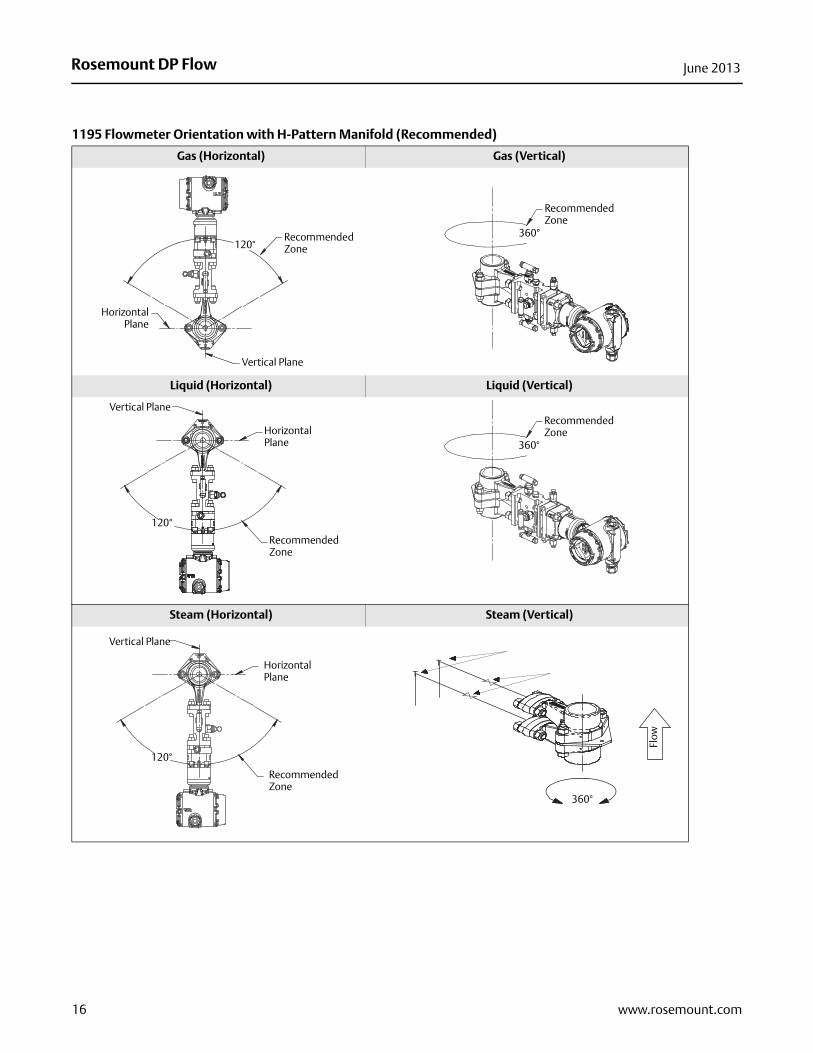
1195 Flowmeter Orientation with H-Pattern Manifold (Recommended)
Gas (Horizontal) Gas (Vertical)
Liquid (Horizontal) Liquid (Vertical)
Steam (Horizontal) Steam (Vertical)
Recommended Zone
Vertical Plane
HorizontalPlane
120°
Recommended Zone
360°
Vertical Plane
Horizontal Plane
Recommended Zone
120°
Recommended Zone
360°
Vertical Plane
Horizontal Plane
Recommended Zone
120°
TT
360°
Flow
16 www.rosemount.com

Rosemount DP FlowJune 2013
17www.rosemount.com

Rosemount DP Flow00813-0800-4485 Rev EC
Product Data SheetJune 2013
Emerson Process ManagementRosemount Inc.8200 Market BoulevardChanhassen, MN 55317 USAT (U.S.) 1-800-999-9307T (International) (952) 906-8888F (952) 906-8889www.rosemount.com
Emerson Process ManagementBlegistrasse 23P.O. Box 1046CH 6341 BaarSwitzerlandT +41 (0) 41 768 6111F +41 (0) 41 768 6300www.rosemount.com
Emerson Process Management Asia Pacific Pte Ltd1 Pandan CrescentSignapore 128461T +65 6777 8211F +65 6777 0947Service Support Hotline: +65 6770 8711Email: [email protected]
Emerson Process Management Latin America1300 Concord Terrace, Suite 400Sunrise Florida 33323 USAT + 1 954 846 5030www.rosemount.com
Standard Terms and Conditions of Sale can be found at www.rosemount.com\terms_of_saleThe Emerson logo is a trade mark and service mark of Emerson Electric Co.Rosemount and the Rosemount logotype are registered trademarks of Rosemount Inc.PlantWeb is a registered trademark of one of the Emerson Process Management group of companies.HART and WirelessHART are registered trademarks of the HART Communication FoundationModbus is a trademark of Modicon, Inc.All other marks are the property of their respective owners.© 2012 Rosemount Inc. All rights reserved.