Embed Size (px)
Citation preview

Rosemount Integral Orifice
Flowmeter Series
Product Data Sheet00813-0100-4686, Rev LA
Catalog 2006 - 2007
Rosemount Integral Orifice
Flowmeter Series
HIGHLY ACCURATE SMALL-BORE FLOW
MEASUREMENT CAPABILITY WITH
MINIMAL INSTALLATION AND
MAINTENANCE REQUIREMENTS
• Improves accuracy and repeatability in 1/2-in.,
1-in., and 11/2-in. line sizes
• Reduces leak points by over 50% and
minimizes line plugging
• Improves reliability with consistent
installations
• Multivariable measurement for gas and steamRosemount 1195, 3051SFP and 3095MFP
www.ro
Contents
Rosemount Integral Orifice Flowmeter Series. . . . . . . . . . . . . . . . . . . . . . . . . . . . . . . . . . . . page 2
1195 Integral Orifice Series Selection Guide. . . . . . . . . . . . . . . . . . . . . . . . . . . . . . . . . . . . . page 3
Rosemount 3051SFP Proplate Flowmeter . . . . . . . . . . . . . . . . . . . . . . . . . . . . . . . . . . . . . . page 4
Specifications . . . . . . . . . . . . . . . . . . . . . . . . . . . . . . . . . . . . . . . . . . . . . . . . . . . . . . page 4
Product Certifications . . . . . . . . . . . . . . . . . . . . . . . . . . . . . . . . . . . . . . . . . . . . . . . page 10
Dimensional Drawings . . . . . . . . . . . . . . . . . . . . . . . . . . . . . . . . . . . . . . . . . . . . . . page 13
Ordering Information . . . . . . . . . . . . . . . . . . . . . . . . . . . . . . . . . . . . . . . . . . . . . . . page 14
Rosemount 3095MFP Mass Proplate Flowmeter . . . . . . . . . . . . . . . . . . . . . . . . . . . . . . . . page 19
Specifications . . . . . . . . . . . . . . . . . . . . . . . . . . . . . . . . . . . . . . . . . . . . . . . . . . . . . page 19
Product Certifications . . . . . . . . . . . . . . . . . . . . . . . . . . . . . . . . . . . . . . . . . . . . . . . page 23
Dimensional Drawings . . . . . . . . . . . . . . . . . . . . . . . . . . . . . . . . . . . . . . . . . . . . . . page 25
Ordering Information . . . . . . . . . . . . . . . . . . . . . . . . . . . . . . . . . . . . . . . . . . . . . . . page 26
Rosemount 1195 Integral Orifice Primary Element . . . . . . . . . . . . . . . . . . . . . . . . . . . . . . . page 29
Specifications . . . . . . . . . . . . . . . . . . . . . . . . . . . . . . . . . . . . . . . . . . . . . . . . . . . . . page 29
Dimensional Drawings . . . . . . . . . . . . . . . . . . . . . . . . . . . . . . . . . . . . . . . . . . . . . . page 32
Ordering Information . . . . . . . . . . . . . . . . . . . . . . . . . . . . . . . . . . . . . . . . . . . . . . . page 33
HART Configuration Data Sheet (CDS) . . . . . . . . . . . . . . . . . . . . . . . . . . . . . . . . . . . . . . . page 38
FOUNDATION fieldbus™ Configuration Data Sheet (CDS) . . . . . . . . . . . . . . . . . . . . . . . . . . page 41
Fluid Data Sheet (FDS) . . . . . . . . . . . . . . . . . . . . . . . . . . . . . . . . . . . . . . . . . . . . . . . . . . . . page 44
semount.com
Product Data Sheet00813-0100-4686, Rev LA
Catalog 2006 - 2007
Rosemount Integral Orifice
Flowmeter Series
2
Rosemount Integral Orifice Flowmeter Series
Industry leading integrated DP flowmeters
By integrating Rosemount pressure transmitters with the
1195 Integral Orifice Series primary element, Rosemount
provides the highest performing DP Flowmeters. This fully
integrated flowmeter eliminates the need for fittings, tubing,
valves, adapters, and mounting brackets, thereby reducing
welding and installation time.
Improves accuracy and repeatability in 1/2-in., 1-in., and
11/2-in. line sizes
Using an integral orifice flowmeter solution will eliminate
the three measurement inaccuracies recorded in small
orifice line installations.
1. The Rosemount 1195 integral orifice honed body
reduces ID uncertainty
2. By inserting precision bored upstream and
downstream sections of pipe, the velocity profile
distortion due to pipe roughness is reduced
3. The self-centering design of the 1195 Integral Orifice
Plate eliminates plate misalignment
Using integral orifice flowmeter solutions will greatly
improve measurement accuracy and repeatability.
Improves reliability and maintenance costs
The integral orifice flowmeter solutions eliminate impulse
lines, reducing leak points by over 50% and decrease
start-up time due to the flexibility of numerous process
connection options. The direct mount design minimizes line
plugging by eliminating long lines, small-bore ports, and
crevices while providing consistently reliable installations.
MultiVariable measurement for gas and steam
Measuring mass flow (base volumetric) in Gas and Steam
reduces process variability. The Embedded Flow Software
re-calculates ALL flow coefficients and calculates density
and mass flow in Real Time. Coupled with DP technology,
the Integral Orifice Flowmeter solution is designed to
maximize performance in real-world conditions.
Advanced PlantWeb® functionality
Rosemount orifice flowmeters power
PlantWeb through a scalable architecture,
advanced diagnostics, and MultiVariable
capabilities. This reduces operational and
maintenance expenditures while improving
throughput and utilities management.
Rosemount DP-Flow Solutions
Annubar® Flowmeter Series: Rosemount
3051SFA ProBar®, 3095MFA Mass ProBar®, 485,
and 285
The state-of-the-art, fifth generation Rosemount 485 Annubar
combined with the 3051S or 3095 MultiVariable transmitter creates
an accurate, repeatable and dependable insertion-type flowmeter.
The Rosemount 285 provides a commercial product offering for
your general purpose applications.
Compact Orifice Flowmeter Series: Rosemount
3051SFC, 3095MFC, and 405
Compact Orifice Flowmeters can be installed between existing
flanges, up to a Class 600 (PN100) rating. In tight fit applications,
a conditioning orifice plate version is available, requiring only two
diameters of straight run upstream.
Integral Orifice Flowmeter Series: Rosemount 3051SFP
ProPlate®, 3095MFP Mass ProPlate, and 1195
These integral orifice flowmeters eliminate the inaccuracies that
become more pronounced in small orifice line installations. The
completely assembled, ready to install flowmeters reduce cost and
simplify installation.
Orifice Plate Primary Element Systems: Rosemount
1495 and 1595 Orifice Plates, 1496 Flange Unions and
1497 Meter Sections
A comprehensive offering of orifice plates, flange unions and
meter sections that is easy to specify and order. The 1595
Conditioning Orifice provides superior performance in tight fit
applications.
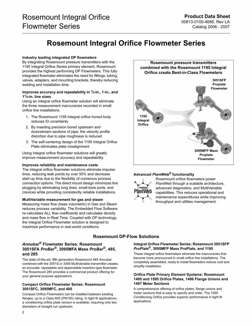
Rosemount pressure transmitters
combined with the Rosemount 1195 Integral
Orifice create Best-in-Class Flowmeters
3051SFP
Proplate
Flowmeter
3095MFP Mass
Proplate
Flowmeter
1195
Integral
Orifice
Product Data Sheet00813-0100-4686, Rev LA
Catalog 2006 - 2007
Rosemount Integral Orifice
Flowmeter Series
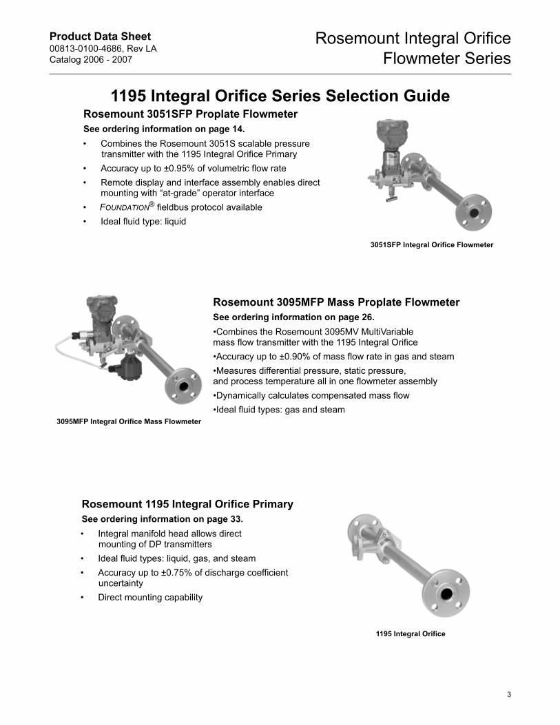
1195 Integral Orifice Series Selection GuideRosemount 3051SFP Proplate Flowmeter
See ordering information on page 14.
• Combines the Rosemount 3051S scalable pressure transmitter with the 1195 Integral Orifice Primary
• Accuracy up to ±0.95% of volumetric flow rate
• Remote display and interface assembly enables direct mounting with “at-grade” operator interface
• FOUNDATION® fieldbus protocol available
• Ideal fluid type: liquid
Rosemount 3095MFP Mass Proplate Flowmeter
See ordering information on page 26.
•Combines the Rosemount 3095MV MultiVariablemass flow transmitter with the 1195 Integral Orifice
•Accuracy up to ±0.90% of mass flow rate in gas and steam
•Measures differential pressure, static pressure, and process temperature all in one flowmeter assembly
•Dynamically calculates compensated mass flow
•Ideal fluid types: gas and steam
Rosemount 1195 Integral Orifice Primary
See ordering information on page 33.
• Integral manifold head allows direct mounting of DP transmitters
• Ideal fluid types: liquid, gas, and steam
• Accuracy up to ±0.75% of discharge coefficient uncertainty
• Direct mounting capability
3095MFP Integral Orifice Mass Flowmeter
1195 Integral Orifice
3051SFP Integral Orifice Flowmeter
3
Product Data Sheet00813-0100-4686, Rev LA
Catalog 2006 - 2007
Rosemount Integral Orifice
Flowmeter Series
Rosemount 3051SFP Proplate Flowmeter
SPECIFICATIONS
Performance
Repeatability
±0.1%
Line Sizes
• 1/2-in. (15 mm)
• 1-in. (25 mm)
• 11/2-in. (40 mm)
Performance Statement Assumptions
• Use associated piping.
• Electronics are trimmed for optimum flow accuracy
Sizing
Contact a Emerson Process Management sales representative for
assistance. A “Configuration Data Sheet” is required prior to order
for application verification.
Functional
Service
• Liquid
• Gas
• Steam
4–20 mA/HART
Zero and Span Adjustment
Zero and span values can be set anywhere within the range.
Span must be greater than or equal to the minimum span.
Output
Two-wire 4–20 mA is user-selectable for linear or square root
output. Digital process variable superimposed on 4–20 mA
signal, available to any host that conforms to the HART
protocol.
Power Supply
External power supply required.
Standard transmitter (4–20 mA): 10.5 to 42.4 V dc with no load
3051S SIS Safety transmitter: 12 to 42 Vdc with no load
3051S HART Diagnostics transmitter: 12 to 42 Vdc with no load
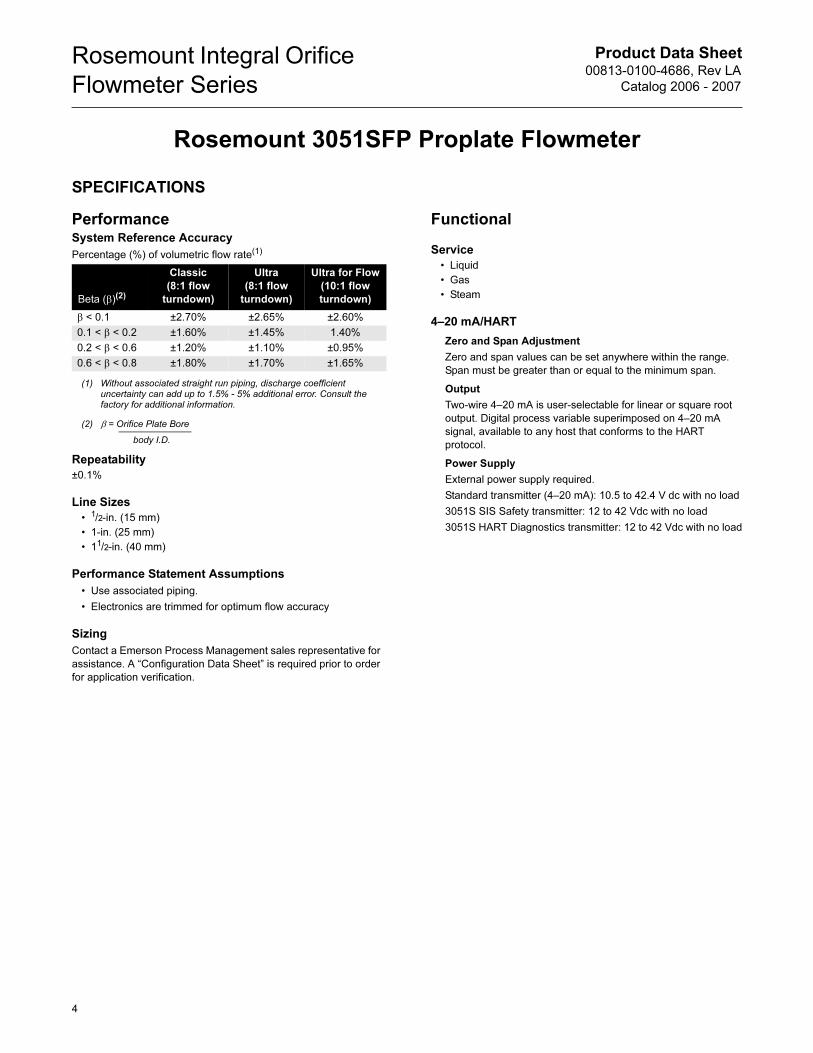
System Reference Accuracy
Percentage (%) of volumetric flow rate(1)
(1) Without associated straight run piping, discharge coefficient uncertainty can add up to 1.5% - 5% additional error. Consult the factory for additional information.
Beta (β)(2)
(2) β = Orifice Plate Bore
body I.D.
Classic
(8:1 flow
turndown)
Ultra
(8:1 flow
turndown)
Ultra for Flow
(10:1 flow
turndown)
β < 0.1 ±2.70% ±2.65% ±2.60%
0.1 < β < 0.2 ±1.60% ±1.45% 1.40%
0.2 < β < 0.6 ±1.20% ±1.10% ±0.95%
0.6 < β < 0.8 ±1.80% ±1.70% ±1.65%
4
Product Data Sheet00813-0100-4686, Rev LA
Catalog 2006 - 2007
Rosemount Integral Orifice
Flowmeter Series
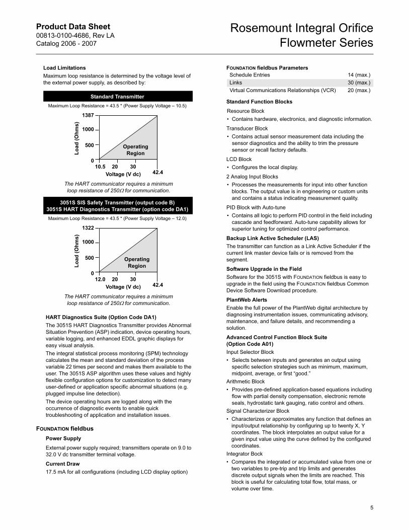
Load Limitations
Maximum loop resistance is determined by the voltage level of
the external power supply, as described by:
HART Diagnostics Suite (Option Code DA1)
The 3051S HART Diagnostics Transmitter provides Abnormal
Situation Prevention (ASP) indication, device operating hours,
variable logging, and enhanced EDDL graphic displays for
easy visual analysis.
The integral statistical process monitoring (SPM) technology
calculates the mean and standard deviation of the process
variable 22 times per second and makes them available to the
user. The 3051S ASP algorithm uses these values and highly
flexible configuration options for customization to detect many
user-defined or application specific abnormal situations (e.g.
plugged impulse line detection).
The device operating hours are logged along with the
occurrence of diagnostic events to enable quick
troubleshooting of application and installation issues.
FOUNDATION fieldbus
Power Supply
External power supply required; transmitters operate on 9.0 to
32.0 V dc transmitter terminal voltage.
Current Draw
17.5 mA for all configurations (including LCD display option)
FOUNDATION fieldbus Parameters
Standard Function Blocks
Resource Block
• Contains hardware, electronics, and diagnostic information.
Transducer Block
• Contains actual sensor measurement data including the
sensor diagnostics and the ability to trim the pressure
sensor or recall factory defaults.
LCD Block
• Configures the local display.
2 Analog Input Blocks
• Processes the measurements for input into other function
blocks. The output value is in engineering or custom units
and contains a status indicating measurement quality.
PID Block with Auto-tune
• Contains all logic to perform PID control in the field including
cascade and feedforward. Auto-tune capability allows for
superior tuning for optimized control performance.
Backup Link Active Scheduler (LAS)
The transmitter can function as a Link Active Scheduler if the
current link master device fails or is removed from the
segment.
Software Upgrade in the Field
Software for the 3051S with FOUNDATION fieldbus is easy to
upgrade in the field using the FOUNDATION fieldbus Common
Device Software Download procedure.
PlantWeb Alerts
Enable the full power of the PlantWeb digital architecture by
diagnosing instrumentation issues, communicating advisory,
maintenance, and failure details, and recommending a
solution.
Advanced Control Function Block Suite
(Option Code A01)
Input Selector Block
• Selects between inputs and generates an output using
specific selection strategies such as minimum, maximum,
midpoint, average, or first “good.”
Arithmetic Block
• Provides pre-defined application-based equations including
flow with partial density compensation, electronic remote
seals, hydrostatic tank gauging, ratio control and others.
Signal Characterizer Block
• Characterizes or approximates any function that defines an
input/output relationship by configuring up to twenty X, Y
coordinates. The block interpolates an output value for a
given input value using the curve defined by the configured
coordinates.
Integrator Bock
• Compares the integrated or accumulated value from one or
two variables to pre-trip and trip limits and generates
discrete output signals when the limits are reached. This
block is useful for calculating total flow, total mass, or
volume over time.
Standard Transmitter
Maximum Loop Resistance = 43.5 * (Power Supply Voltage – 10.5)
The HART communicator requires a minimum
loop resistance of 250Ω for communication.
3051S SIS Safety Transmitter (output code B)
3051S HART Diagnostics Transmitter (option code DA1)
Maximum Loop Resistance = 43.5 * (Power Supply Voltage – 12.0)
The HART communicator requires a minimum
loop resistance of 250Ω for communication.
Voltage (V dc)
Lo
ad
(O
hm
s)
Operating
Region
1387
1000
500
010.5 20 30
42.4
Voltage (V dc)
Lo
ad
(O
hm
s)
Operating
Region
1322
1000
500
012.0 20 30
42.4
Schedule Entries 14 (max.)
Links 30 (max.)
Virtual Communications Relationships (VCR) 20 (max.)
5
Product Data Sheet00813-0100-4686, Rev LA
Catalog 2006 - 2007
Rosemount Integral Orifice
Flowmeter Series
Output Splitter Block
• Splits the output of one PID or other control block so that the
PID will control two valves or other actuators.
Control Selector Block
• Selects one of up to three inputs (highest, middle, or lowest)
that are normally connected to the outputs of PID or other
control function blocks.
Fully Compensated Mass Flow Block (Option Code H01)
Calculates fully compensated mass flow based on differential
pressure with external process pressure and temperature
measurements over the fieldbus segment. Configuration for
the mass flow calculation is easily accomplished using the
Rosemount 3095 Engineering Assistant.
FOUNDATION fieldbus Diagnostics Suite (Option Code D01)
3051S FOUNDATION fieldbus Diagnostics provide Abnormal
Situation Prevention (ASP) indication and enhanced EDDL
graphic displays for easy visual analysis.
The integral statistical process monitoring (SPM) technology
calculates the mean and standard deviation of the process
variable 22 times per second and makes them available to the
user. The 3051S ASP algorithm uses these values and highly
flexible configuration options for customization to detect many
user-defined or application specific abnormal situations (e.g.
plugged impulse line detection).
Process Temperature Limits
Direct Mount Electronics
• –40 to 450 °F (40 to 232 °C)
Remote Mount Electronics
• –148 to 850 °F (–100 to 454 °C)(1)
Electronics Temperature Limits
Ambient
• –40 to 185 °F (–40 to 85 °C)
• With Integral Mount LCD Display: –4 to 175 °F (–20 to 80 °C)
Storage
• –50 to 230 °F (–46 to 110 °C)
• With Integral Mount LCD Display: –40 to 185 °F (–40 to 85 °C)
Pressure Limits(2)
Direct Mount Electronics
• Pressure retention per ANSI B16.5 600# or DIN PN
Static Pressure Limits
• Range 1A: Operates within specification between static line
pressures of 0.5 psia to 2000 psig (0.03 to 138 bar)
• Ranges 2A– 3A: Operates within specifications between
static line pressures of 0.5 psia and 3626 psig (0.03 bar-A to
250 bar-G)
Burst Pressure Limits
Coplanar or traditional process flange
• 10000 psig (689,5 bar).
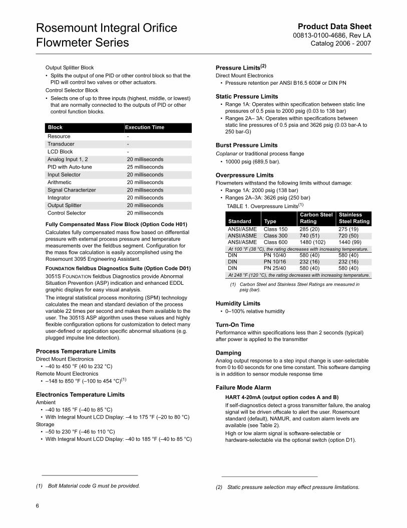
Overpressure Limits
Flowmeters withstand the following limits without damage:
• Range 1A: 2000 psig (138 bar)
• Ranges 2A–3A: 3626 psig (250 bar)
Humidity Limits
• 0–100% relative humidity
Turn-On Time
Performance within specifications less than 2 seconds (typical)
after power is applied to the transmitter
Damping
Analog output response to a step input change is user-selectable
from 0 to 60 seconds for one time constant. This software damping
is in addition to sensor module response time
Failure Mode Alarm
HART 4-20mA (output option codes A and B)
If self-diagnostics detect a gross transmitter failure, the analog
signal will be driven offscale to alert the user. Rosemount
standard (default), NAMUR, and custom alarm levels are
available (see Table 2).
High or low alarm signal is software-selectable or
hardware-selectable via the optional switch (option D1).
Block Execution Time
Resource -
Transducer -
LCD Block -
Analog Input 1, 2 20 milliseconds
PID with Auto-tune 25 milliseconds
Input Selector 20 milliseconds
Arithmetic 20 milliseconds
Signal Characterizer 20 milliseconds
Integrator 20 milliseconds
Output Splitter 20 milliseconds
Control Selector 20 milliseconds
(1) Bolt Material code G must be provided. (2) Static pressure selection may effect pressure limitations.
TABLE 1. Overpressure Limits(1)
(1) Carbon Steel and Stainless Steel Ratings are measured in psig (bar).
Standard Type
Carbon Steel
Rating
Stainless
Steel Rating
ANSI/ASME Class 150 285 (20) 275 (19)
ANSI/ASME Class 300 740 (51) 720 (50)
ANSI/ASME Class 600 1480 (102) 1440 (99)
At 100 °F (38 °C), the rating decreases with increasing temperature.
DIN PN 10/40 580 (40) 580 (40)
DIN PN 10/16 232 (16) 232 (16)
DIN PN 25/40 580 (40) 580 (40)
At 248 °F (120 °C), the rating decreases with increasing temperature.
6
Product Data Sheet00813-0100-4686, Rev LA
Catalog 2006 - 2007
Rosemount Integral Orifice
Flowmeter Series
3051
-305
1_17
A
3051S SIS Safety Transmitter Failure Values
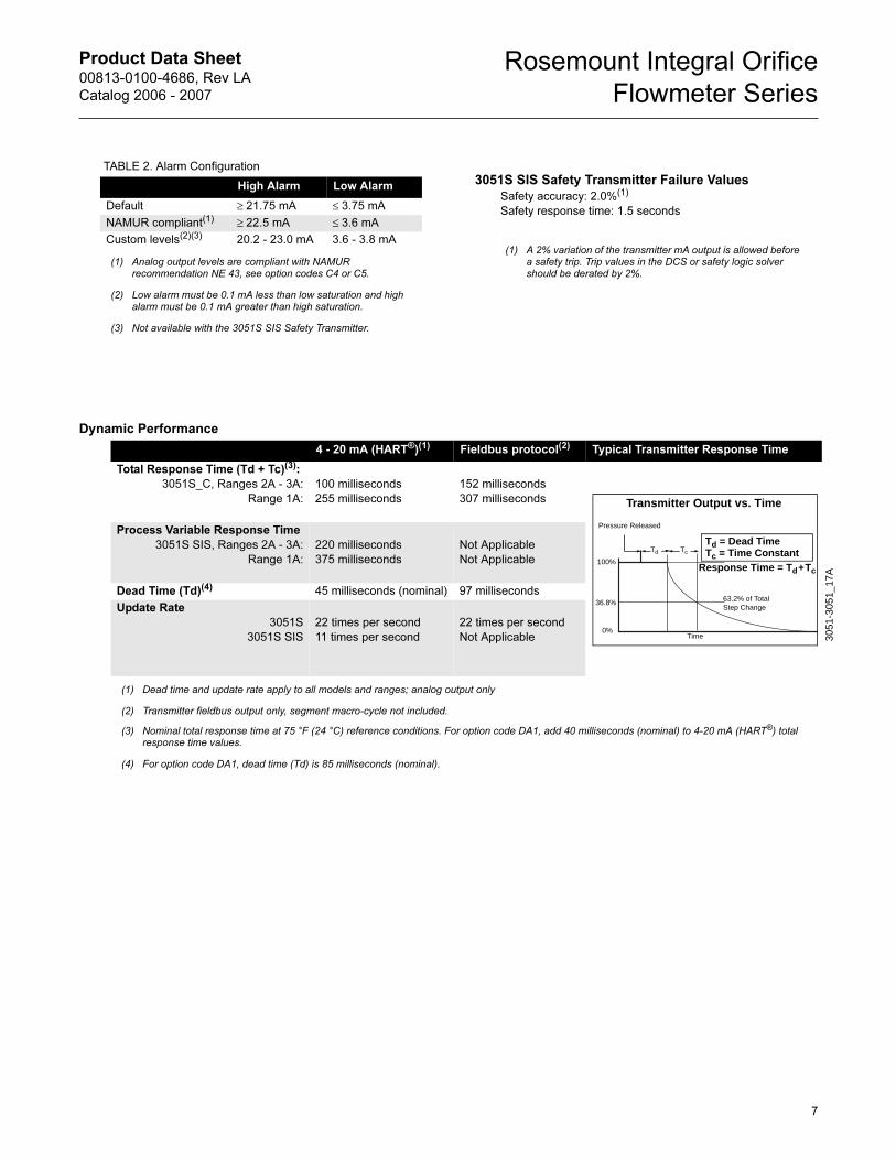
Dynamic Performance
TABLE 2. Alarm Configuration
High Alarm Low Alarm
Default ≥ 21.75 mA ≤ 3.75 mA
NAMUR compliant(1)
(1) Analog output levels are compliant with NAMUR recommendation NE 43, see option codes C4 or C5.
(2) Low alarm must be 0.1 mA less than low saturation and high alarm must be 0.1 mA greater than high saturation.
(3) Not available with the 3051S SIS Safety Transmitter.
≥ 22.5 mA ≤ 3.6 mA
Custom levels(2)(3) 20.2 - 23.0 mA 3.6 - 3.8 mA
Safety accuracy: 2.0%(1)
Safety response time: 1.5 seconds
(1) A 2% variation of the transmitter mA output is allowed before a safety trip. Trip values in the DCS or safety logic solver should be derated by 2%.
4 - 20 mA (HART®)(1) Fieldbus protocol(2) Typical Transmitter Response Time
Total Response Time (Td + Tc)(3):
3051S_C, Ranges 2A - 3A:
Range 1A:
100 milliseconds
255 milliseconds
152 milliseconds
307 milliseconds
Process Variable Response Time
3051S SIS, Ranges 2A - 3A:
Range 1A:
220 milliseconds
375 milliseconds
Not Applicable
Not Applicable
Dead Time (Td)(4) 45 milliseconds (nominal) 97 milliseconds
Update Rate
3051S
3051S SIS
22 times per second
11 times per second
22 times per second
Not Applicable
(1) Dead time and update rate apply to all models and ranges; analog output only
(2) Transmitter fieldbus output only, segment macro-cycle not included.
(3) Nominal total response time at 75 °F (24 °C) reference conditions. For option code DA1, add 40 milliseconds (nominal) to 4-20 mA (HART®) total response time values.
(4) For option code DA1, dead time (Td) is 85 milliseconds (nominal).
TcTd
Td = Dead TimeTc = Time Constant
Pressure Released
Response Time = Td+Tc
63.2% of TotalStep Change
Time0%
100%
36.8%
Transmitter Output vs. Time
7
Product Data Sheet00813-0100-4686, Rev LA
Catalog 2006 - 2007
Rosemount Integral Orifice
Flowmeter Series
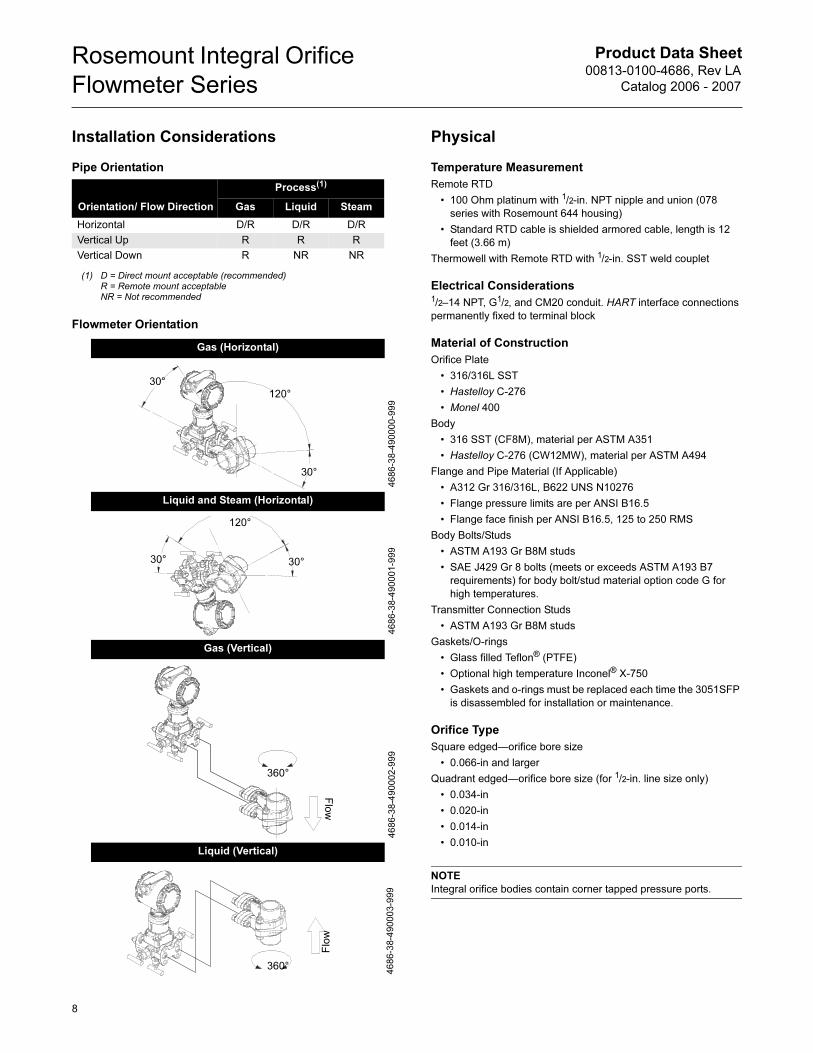
Installation Considerations
Pipe Orientation
Flowmeter Orientation
Physical
Temperature Measurement
Remote RTD
• 100 Ohm platinum with 1/2-in. NPT nipple and union (078
series with Rosemount 644 housing)
• Standard RTD cable is shielded armored cable, length is 12
feet (3.66 m)
Thermowell with Remote RTD with 1/2-in. SST weld couplet
Electrical Considerations1/2–14 NPT, G1/2, and CM20 conduit. HART interface connections
permanently fixed to terminal block
Material of Construction
Orifice Plate
• 316/316L SST
• Hastelloy C-276
• Monel 400
Body
• 316 SST (CF8M), material per ASTM A351
• Hastelloy C-276 (CW12MW), material per ASTM A494
Flange and Pipe Material (If Applicable)
• A312 Gr 316/316L, B622 UNS N10276
• Flange pressure limits are per ANSI B16.5
• Flange face finish per ANSI B16.5, 125 to 250 RMS
Body Bolts/Studs
• ASTM A193 Gr B8M studs
• SAE J429 Gr 8 bolts (meets or exceeds ASTM A193 B7
requirements) for body bolt/stud material option code G for
high temperatures.
Transmitter Connection Studs
• ASTM A193 Gr B8M studs
Gaskets/O-rings
• Glass filled Teflon® (PTFE)
• Optional high temperature Inconel® X-750
• Gaskets and o-rings must be replaced each time the 3051SFP
is disassembled for installation or maintenance.
Orifice Type
Square edged—orifice bore size
• 0.066-in and larger
Quadrant edged—orifice bore size (for 1/2-in. line size only)
• 0.034-in
• 0.020-in
• 0.014-in
• 0.010-in
NOTE
Integral orifice bodies contain corner tapped pressure ports.
Orientation/ Flow Direction
Process(1)
(1) D = Direct mount acceptable (recommended)R = Remote mount acceptableNR = Not recommended
Gas Liquid Steam
Horizontal D/R D/R D/R
Vertical Up R R R
Vertical Down R NR NR
Gas (Horizontal)
Liquid and Steam (Horizontal)
Gas (Vertical)
Liquid (Vertical)
30°
30°
120°4686-38-490000-999
30° 30°
120°
4686-38-490001-999
360°
Flow
4686-38-490002-999
360°
Flow
4686-38-490003-999
8
Product Data Sheet00813-0100-4686, Rev LA
Catalog 2006 - 2007
Rosemount Integral Orifice
Flowmeter Series
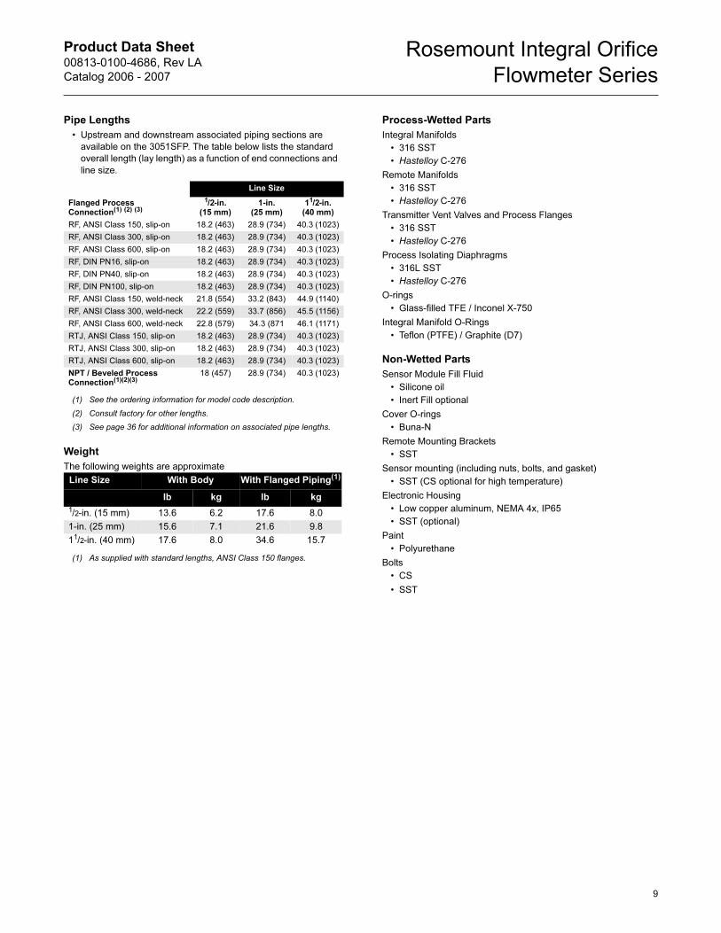
Pipe Lengths
• Upstream and downstream associated piping sections are
available on the 3051SFP. The table below lists the standard
overall length (lay length) as a function of end connections and
line size.
Weight
The following weights are approximate
Process-Wetted Parts
Integral Manifolds
• 316 SST
• Hastelloy C-276
Remote Manifolds
• 316 SST
• Hastelloy C-276
Transmitter Vent Valves and Process Flanges
• 316 SST
• Hastelloy C-276
Process Isolating Diaphragms
• 316L SST
• Hastelloy C-276
O-rings
• Glass-filled TFE / Inconel X-750
Integral Manifold O-Rings
• Teflon (PTFE) / Graphite (D7)
Non-Wetted Parts
Sensor Module Fill Fluid
• Silicone oil
• Inert Fill optional
Cover O-rings
• Buna-N
Remote Mounting Brackets
• SST
Sensor mounting (including nuts, bolts, and gasket)
• SST (CS optional for high temperature)
Electronic Housing
• Low copper aluminum, NEMA 4x, IP65
• SST (optional)
Paint
• Polyurethane
Bolts
• CS
• SST
Line Size
Flanged Process Connection(1) (2) (3)
(1) See the ordering information for model code description.
(2) Consult factory for other lengths.
(3) See page 36 for additional information on associated pipe lengths.
1/2-in. (15 mm)
1-in. (25 mm)
11/2-in. (40 mm)
RF, ANSI Class 150, slip-on 18.2 (463) 28.9 (734) 40.3 (1023)
RF, ANSI Class 300, slip-on 18.2 (463) 28.9 (734) 40.3 (1023)
RF, ANSI Class 600, slip-on 18.2 (463) 28.9 (734) 40.3 (1023)
RF, DIN PN16, slip-on 18.2 (463) 28.9 (734) 40.3 (1023)
RF, DIN PN40, slip-on 18.2 (463) 28.9 (734) 40.3 (1023)
RF, DIN PN100, slip-on 18.2 (463) 28.9 (734) 40.3 (1023)
RF, ANSI Class 150, weld-neck 21.8 (554) 33.2 (843) 44.9 (1140)
RF, ANSI Class 300, weld-neck 22.2 (559) 33.7 (856) 45.5 (1156)
RF, ANSI Class 600, weld-neck 22.8 (579) 34.3 (871 46.1 (1171)
RTJ, ANSI Class 150, slip-on 18.2 (463) 28.9 (734) 40.3 (1023)
RTJ, ANSI Class 300, slip-on 18.2 (463) 28.9 (734) 40.3 (1023)
RTJ, ANSI Class 600, slip-on 18.2 (463) 28.9 (734) 40.3 (1023)
NPT / Beveled Process Connection(1)(2)(3)
18 (457) 28.9 (734) 40.3 (1023)
Line Size With Body With Flanged Piping(1)
(1) As supplied with standard lengths, ANSI Class 150 flanges.
lb kg lb kg
1/2-in. (15 mm) 13.6 6.2 17.6 8.0
1-in. (25 mm) 15.6 7.1 21.6 9.8
11/2-in. (40 mm) 17.6 8.0 34.6 15.7
9
Product Data Sheet00813-0100-4686, Rev LA
Catalog 2006 - 2007
Rosemount Integral Orifice
Flowmeter Series
PRODUCT CERTIFICATIONS
Approved Manufacturing LocationsRosemount Inc. — Chanhassen, Minnesota USA
Emerson Process Management GmbH & Co. — Wessling,
Germany
Emerson Process Management Asia Pacific Private Limited —
Singapore
Beijing Rosemount Far East Instrument Co., LTD — Beijing, China
European Directive InformationThe EC declaration of conformity for all applicable European
directives for this product can be found at www.rosemount.com. A
hard copy may be obtained by contacting an Emerson Process
Management representative.
ATEX Directive (94/9/EC)
Emerson Process Management complies with the
ATEX Directive.
European Pressure Equipment Directive (PED) (97/23/EC)
Models 3051S_CA4; 3051S_CD2, 3, 4, 5; (also with P9 option)
Pressure Transmitters — QS Certificate of Assessment -
EC No. PED-H-20, Module H Conformity Assessment
All other Model 3051S Pressure Transmitters
— Sound Engineering Practice
Transmitter Attachments: Diaphragm Seal - Process Flange -
Manifold — Sound Engineering Practice
Primary Elements, Flowmeter
— See appropriate Primary Element QIG
Electro Magnetic Compatibility (EMC) (89/336/EEC)
All Models: EN 50081-1: 1992; EN 50082-2:1995;
EN 61326-1:1997 – Industrial
Ordinary Location Certification for FMAs standard, the transmitter has been examined and tested to
determine that the design meets basic electrical, mechanical, and
fire protection requirements by FM, a nationally recognized testing
laboratory (NRTL) as accredited by the Federal Occupational
Safety and Health Administration (OSHA).
Hazardous Locations Certifications
North American Certifications
FM Approvals
E5 Explosion-proof for Class I, Division 1, Groups B, C, and D;
dust-ignition proof for Class II and Class III, Division 1,
Groups E, F, and G; hazardous locations; enclosure Type
4X, conduit seal not required when installed according to
Rosemount drawing 03151-1003.
I5/IE Intrinsically Safe for use in Class I, Division 1, Groups A, B,
C, and D; Class II, Division 1, Groups E, F, and G; Class III,
Division 1; Class I, Zone 0 AEx ia IIC when connected in
accordance with Rosemount drawing 03151-1006;
Non-incendive for Class I, Division 2, Groups A, B, C, and D
Enclosure Type 4X
For entity parameters see control drawing 03151-1006.
Canadian Standards Association (CSA)
E6 Explosion-proof for Class I, Division 1, Groups B, C, and D;
Dust-Ignition-Proof for Class II and Class III, Division 1,
Groups E, F, and G; suitable for Class I, Division 2, Groups
A, B, C, and D, when installed per Rosemount drawing
03151-1013, CSA Enclosure Type 4X; conduit seal not
required.
I6/IF Intrinsically Safe for Class I, Division 1, Groups A, B, C, and
D when connected in accordance with Rosemount drawings
03151-1016;
For entity parameters see control drawing 03151-1016.
European Certifications
I1/IA ATEX Intrinsic Safety
Certificate No.: BAS01ATEX1303X II 1G
EEx ia IIC T5 (-60°C ≤ Ta ≤ 40°C)
T4 (-60°C ≤ Ta ≤ 70°C)
T4 (-60°C ≤ Ta ≤ 40°C) (FISCO)
1180
Special conditions for safe use (x)
1. The apparatus, excluding the Types 3051 S-T and 3051
S-C (In-line and Coplanar SuperModules respectively), is
not capable of withstanding the 500V test as defined in
Clause 6.4.12 of EN 50020. This must be considered
during installation.
2. The terminal pins of the Types 3051 S-T and 3051 S-C
must be protected to IP20 minimum.
TABLE 3. Input Parameters
Loop / Power Groups
Ui = 30 V HART / FOUNDATION fieldbus/
Remote Display / SIS
Ui = 17.5 V FISCO
Ii = 300 mA HART / FOUNDATION fieldbus/
Remote Display / SIS
Ii = 380 mA FISCO
Pi = 1.0 W HART / Remote Display / SIS
Pi = 1.3 W FOUNDATION fieldbus
Pi = 5.32 W FISCO
Ci = 30 nF SuperModule™ Platform
Ci = 11.4 nF HART / SIS
Ci = 0 FOUNDATION fieldbus / Remote
Display / FISCO
Li = 0 HART / FOUNDATION fieldbus/ SIS
/ FISCO
Li = 60 µH Remote Display
10
Product Data Sheet00813-0100-4686, Rev LA
Catalog 2006 - 2007
Rosemount Integral Orifice
Flowmeter Series
N1 ATEX Type n
Certificate No.: BAS01ATEX3304X II 3 G
EEx nL IIC T5 (Ta = -40 °C TO 70 °C)
Ui = 45 Vdc max
IP66
Special conditions for safe use (x)
The apparatus is not capable of withstanding the 500V
insulation test required by Clause 9.1 of EN 50021: 1999.
This must be taken into account when installing the
apparatus.
ND ATEX Dust
Certificate No.: BAS01ATEX1374X II 1 D
T105°C (-20 °C ≤ Tamb ≤ 85 °C)
Vmax = 42.4 volts max
A = 24 mA
IP66
1180
Special conditions for safe use (x)
1. The user must ensure that the maximum rated voltage
and current (42.4 volts, 22 milliampere, DC) are not
exceeded. All connections to other apparatus or
associated apparatus shall have control over this voltage
and current equivalent to a category “ib” circuit according
to EN 50020.
2. Cable entries must be used which maintain the ingress
protection of the enclosure to at least IP66.
3. Unused cable entries must be filled with suitable blanking
plugs which maintain the ingress protection of the
enclosure to at least IP66.
4. Cable entries and blanking plugs must be suitable for the
ambient range of the apparatus and capable of
withstanding a 7J impact test.
5. The 3051S must be securely screwed in place to maintain
the ingress protection of the enclosure.
E1 ATEX Flameproof
Certificate No.: KEMA00ATEX2143X II 1/2 G
EEx d IIC T6 (-50 °C ≤ Tamb ≤ 65 °C)
EEx d IIC T5 (-50 °C ≤ Tamb ≤ 80 °C)
Vmax = 42.4V
1180
Special conditions for safe use (x)
This device contains a thin wall diaphragm. Installation,
maintenance and use shall take into account the
environmental conditions to which the diaphragm will be
subjected. The manufacturer’s instructions for installation
and maintenance shall be followed in detail to assure safety
during its expected lifetime. The Model 3051S pressure
transmitter must include a Series 300S housing integrally
mounted to a Series Model 3051S Sensor module as per
Rosemount drawing 03151-1023.
Japanese Certifications
E4 JIS Flameproof
Ex d IIC T6
Australian Certifications
E7 SAA Explosion-proof and DIP
Certification No.: AUS Ex 3798X
Ex d IIC T6 (Ta = 60°C) IP66
DIP A21 TA T6 (Ta = 60°C) IP66
Special conditions for safe use (x)
1. It is a condition of manufacture that each transmitter
module shall be pressure tested in accordance with clause
4.3 of AS 2380.2 at minimum pressure of 1450 kPa. As the
model 300S housing passed tests at 4 times the reference
pressures (400 kPa for single and 3800 kPa for dual
compartment housing) and are not of welded construction,
they may be exempted from the routing pressure test of
clause 4.3 of AS 2380.2.
2. It is a condition of manufacture that each transmitter
module and housing combination shall be subjected to a
routine high voltage test in accordance with clause 6.2 of
AS 2380.1, with the following variation. The test voltage
applied to each single or dual compartment housing shall
not be less than 500 V, 47 to 62 Hz, for a period of not less
than one minute, with a breakdown current of less than 5
mA.
3. It is a condition of safe use that each housing shall be
connected to external circuits via suitable conduit or
Standards Australia certified cable glands. Where only one
entry is used for connection to external circuits, the unused
entry shall be closed by means of the blanking plug
supplied by the equipment manufacturer or by a suitable
Standards Australia certified blanking plug.
4. It is a condition of safe use that a dielectric strength test
shall be applied whenever the terminal block is changed or
replaced in either the dual compartment or single
compartment housings. The breakdown current shall be
less than 5 mA, when 500 V, 47 to 62 Hz, is applied for one
minute. Note: if tested with an optional T1 transient
protector terminal block fitted, the protection will operate
and hence there will be no current indicated.
5. It is a condition of safe use that each transmitter module
shall be used with a Model 300S housing, in order to
comply with flameproof requirements.
Certificate Description
TC15682 Coplanar with Junction Box Housing
TC15683 Coplanar with PlantWeb Housing
TC15684 Coplanar with PlantWeb Housing
and LCD Display
TC15685 In-Line SST with Junction Box Housing
TC15686 In-Line Hastelloy with Junction Box Housing
TC15687 In-Line SST with PlantWeb Housing
TC15688 In-Line Hastelloy with Plantweb Housing
TC15689 In-Line SST with Plantweb Housing
and LCD Display
TC15690 In-Line Hastelloy with PlantWeb Housing
and LCD Display
11
Product Data Sheet00813-0100-4686, Rev LA
Catalog 2006 - 2007
Rosemount Integral Orifice
Flowmeter Series
6. It is a condition of safe use that each model 300S housing
fitted with a transmitter module shall be marked with the
same certification marking code information. Should the
housing be replaced after initial supply to another model
300S housing, the replacement housing shall have the
same certification marking code information as the
housing it replaces.
IECEx Certifications
I7/IG IECEx Intrinsic Safety
Certificate No.: IECExBAS04.0017X
Ex ia IIC T5 (Ta = -60 °C to 40 °C) -HART/SIS/Remote Meter
Ex ia IIC T4 (Ta = -60 °C to 70 °C) -HART/SIS/Remote Meter
Ex ia IIC T4 (Ta = -60 °C to 70 °C) -FOUNDATION Fieldbus
Ex ia IIC T4 (Ta = -60 °C to 40 °C) -FISCO
IP66
Special conditions for safe use (x)
1.The Models 3051S HART 4-20mA, 3051S Fieldbus,
3051S Profibus and 3051S FISCO are not capable of
withstanding the 500V test as defined in clause 6.4.12 of
IEC 60079-11. This must be taken into account during
installation.
2.The terminal pins of the Types 3051S-T and 3051S-C
must be protected to IP20 minimum.
N7 IECEx Type n
Certificate No.: IECExBAS04.0018X
Ex nC IIC T5 (Ta = -40 °C to 70 °C)
Ui = 45 Vdc MAX
IP66
Special conditions for safe use (x)
The apparatus is not capable of withstanding the 500 V
insulation test required by Clause 8 of IEC 79-15: 1987.
Combinations of Certifications
Stainless steel certification tag is provided when optional approval
is specified. Once a device labeled with multiple approval types is
installed, it should not be reinstalled using any other approval
types. Permanently mark the approval label to distinguish it from
unused approval types.
K1 Combination of E1, I1, N1, and ND
K5 Combination of E5 and I5
K6 Combination of E6 and I6
K7 Combination of E7, I7, and N7
KA Combination of E1, I1, E6, and I6
KB Combination of E5, I5, I6 and E6
KC Combination of E5, E1, I5 and I1
KD Combination of E5, I5, E6, I6, E1, and I1
TABLE 4. Input Parameters
Loop / Power Groups
Ui = 30 V HART / FOUNDATION fieldbus/
Remote Display / SIS
Ui = 17.5 V FISCO
Ii = 300 mA HART / FOUNDATION fieldbus/
Remote Display / SIS
Ii = 380 mA FISCO
Pi = 1.0 W HART / Remote Display / SIS
Pi = 1.3 W FOUNDATION fieldbus
Pi = 5.32 W FISCO
Ci = 30 nF SuperModule™ Platform
Ci = 11.4 nF HART / SIS
Ci = 0 FOUNDATION fieldbus / Remote
Display / FISCO
Li = 0 HART / FOUNDATION fieldbus/ SIS
/ FISCO
12
Product Data Sheet00813-0100-4686, Rev LA
Catalog 2006 - 2007
Rosemount Integral Orifice
Flowmeter Series
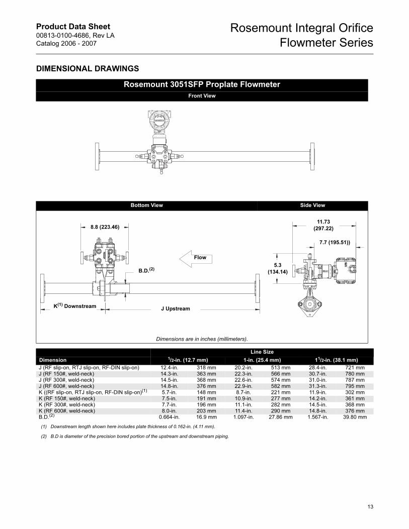
DIMENSIONAL DRAWINGS
Rosemount 3051SFP Proplate Flowmeter
Front View
Bottom View Side View
Dimensions are in inches (millimeters).
Line Size
Dimension 1/2-in. (12.7 mm) 1-in. (25.4 mm) 11/2-in. (38.1 mm)
J (RF slip-on, RTJ slip-on, RF-DIN slip-on) 12.4-in. 318 mm 20.2-in. 513 mm 28.4-in. 721 mmJ (RF 150#, weld-neck) 14.3-in. 363 mm 22.3-in. 566 mm 30.7-in. 780 mmJ (RF 300#, weld-neck) 14.5-in. 368 mm 22.6-in. 574 mm 31.0-in. 787 mmJ (RF 600#, weld-neck) 14.8-in. 376 mm 22.9-in. 582 mm 31.3-in. 795 mmK ((RF slip-on, RTJ slip-on, RF-DIN slip-on)(1) 5.7-in. 148 mm 8.7-in. 221 mm 11.9-in. 302 mmK (RF 150#, weld-neck) 7.5-in. 191 mm 10.9-in. 277 mm 14.2-in. 361 mmK (RF 300#, weld-neck) 7.7-in. 196 mm 11.1-in. 282 mm 14.5-in. 368 mmK (RF 600#, weld-neck) 8.0-in. 203 mm 11.4-in. 290 mm 14.8-in. 376 mmB.D.(2) 0.664-in. 16.9 mm 1.097-in. 27.86 mm 1.567-in. 39.80 mm
(1) Downstream length shown here includes plate thickness of 0.162-in. (4.11 mm).
(2) B.D is diameter of the precision bored portion of the upstream and downstream piping.
Flow
8.8 (223.46)
J UpstreamK(1) Downstream
5.3
(134.14)
11.73
(297.22)
7.7 (195.51))
B.D.(2)
13

Product Data Sheet00813-0100-4686, Rev LA
Catalog 2006 - 2007
Rosemount Integral Orifice
Flowmeter Series
ORDERING INFORMATION
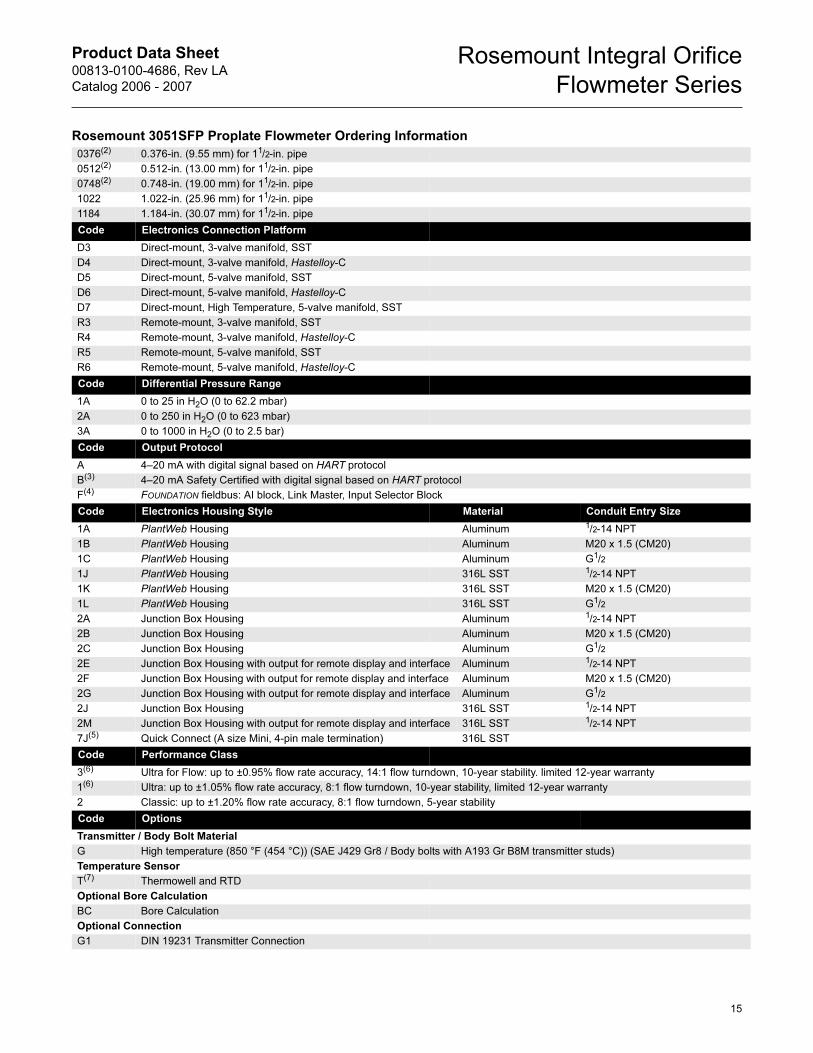
Rosemount 3051SFP Proplate Flowmeter Ordering Information
Model Product Description
3051SFP Proplate Flowmeter
Code Measurement Type
D Differential Pressure
Code Body Material
S 316 SST
H Hastelloy C-276
Code Line Size
005 1/2-in. (15 mm)
010 1-in. (25 mm)
015 11/2-in. (40 mm)
Code Process Connection
T1 NPT Female Body (not available with remote thermowell and RTD)
S1(1) Socket Weld Body (not available with remote thermowell and RTD)
P1 Pipe Ends: NPT threaded
P2 Pipe Ends: Beveled
A1 Pipe Ends: Flanged, RF, ANSI Class 150, slip-on
A3 Pipe Ends: Flanged, RF, ANSI Class 300, slip-on
A6 Pipe Ends: Flanged, RF, ANSI Class 600, slip-on
D1 Pipe Ends: Flanged, RF, DIN PN16, slip-on
D2 Pipe Ends: Flanged, RF, DIN PN40, slip-on
D3 Pipe Ends: Flanged, RF, DIN PN100, slip-on
W1 Pipe Ends: Flanged, RF, ANSI Class 150, weld-neck
W3 Pipe Ends: Flanged, RF, ANSI Class 300, weld-neck
W6 Pipe Ends: Flanged, RF, ANSI Class 600, weld-neck
R1 Pipe Ends: Flanged, RTJ, ANSI Class 150, slip-on
R3 Pipe Ends: Flanged, RTJ, ANSI Class 300, slip-on
R6 Pipe Ends: Flanged, RTJ, ANSI Class 600, slip-on
P9 Special process connections
Code Orifice Plate Material
S 316 SST
H Hastelloy C-276
M Monel
Code Bore Size Option
0010 0.010-in. (0.25 mm) for 1/2-in. pipe
0014 0.014-in. (0.36 mm) for 1/2-in. pipe
0020 0.020-in. (0.51 mm) for 1/2-in. pipe
0034 0.034-in. (0.86 mm) for 1/2-in. pipe
0066 0.066-in. (1.68 mm) for 1/2-in. pipe
0109 0.109-in. (2.77 mm) for 1/2-in. pipe
0160(2) 0.160-in. (4.06 mm) for 1/2-in. pipe
0196(2) 0.196-in. (4.98 mm) for 1/2-in. pipe
0260(2) 0.260-in. (6.60 mm) for 1/2-in. pipe
0340(2) 0.340-in. (8.64 mm) for 1/2-in. pipe
0150 0.150-in. (3.81 mm) for 1-in. pipe
0250(2) 0.250-in. (6.35 mm) for 1-in. pipe
0345(2) 0.345-in. (8.76 mm) for 1-in. pipe
0500(2) 0.500-in. (12.70 mm) for 1-in. pipe
0630(2) 0.630-in. (16.00 mm) for 1-in. pipe
0800 0.800-in. (20.32 mm) for 1-in. pipe
0295 0.295-in. (7.49 mm) for 11/2-in. pipe
14
Product Data Sheet00813-0100-4686, Rev LA
Catalog 2006 - 2007
Rosemount Integral Orifice
Flowmeter Series
0376(2) 0.376-in. (9.55 mm) for 11/2-in. pipe
0512(2) 0.512-in. (13.00 mm) for 11/2-in. pipe
0748(2) 0.748-in. (19.00 mm) for 11/2-in. pipe
1022 1.022-in. (25.96 mm) for 11/2-in. pipe
1184 1.184-in. (30.07 mm) for 11/2-in. pipe
Code Electronics Connection Platform
D3 Direct-mount, 3-valve manifold, SST
D4 Direct-mount, 3-valve manifold, Hastelloy-C
D5 Direct-mount, 5-valve manifold, SST
D6 Direct-mount, 5-valve manifold, Hastelloy-C
D7 Direct-mount, High Temperature, 5-valve manifold, SST
R3 Remote-mount, 3-valve manifold, SST
R4 Remote-mount, 3-valve manifold, Hastelloy-C
R5 Remote-mount, 5-valve manifold, SST
R6 Remote-mount, 5-valve manifold, Hastelloy-C
Code Differential Pressure Range
1A 0 to 25 in H2O (0 to 62.2 mbar)
2A 0 to 250 in H2O (0 to 623 mbar)
3A 0 to 1000 in H2O (0 to 2.5 bar)
Code Output Protocol
A 4–20 mA with digital signal based on HART protocol
B(3) 4–20 mA Safety Certified with digital signal based on HART protocol
F(4) FOUNDATION fieldbus: AI block, Link Master, Input Selector Block
Code Electronics Housing Style Material Conduit Entry Size
1A PlantWeb Housing Aluminum 1/2-14 NPT
1B PlantWeb Housing Aluminum M20 x 1.5 (CM20)
1C PlantWeb Housing Aluminum G1/2
1J PlantWeb Housing 316L SST 1/2-14 NPT
1K PlantWeb Housing 316L SST M20 x 1.5 (CM20)
1L PlantWeb Housing 316L SST G1/2
2A Junction Box Housing Aluminum 1/2-14 NPT
2B Junction Box Housing Aluminum M20 x 1.5 (CM20)
2C Junction Box Housing Aluminum G1/2
2E Junction Box Housing with output for remote display and interface Aluminum 1/2-14 NPT
2F Junction Box Housing with output for remote display and interface Aluminum M20 x 1.5 (CM20)
2G Junction Box Housing with output for remote display and interface Aluminum G1/2
2J Junction Box Housing 316L SST 1/2-14 NPT
2M Junction Box Housing with output for remote display and interface 316L SST 1/2-14 NPT
7J(5) Quick Connect (A size Mini, 4-pin male termination) 316L SST
Code Performance Class
3(6) Ultra for Flow: up to ±0.95% flow rate accuracy, 14:1 flow turndown, 10-year stability. limited 12-year warranty
1(6) Ultra: up to ±1.05% flow rate accuracy, 8:1 flow turndown, 10-year stability, limited 12-year warranty
2 Classic: up to ±1.20% flow rate accuracy, 8:1 flow turndown, 5-year stability
Code Options
Transmitter / Body Bolt Material
G High temperature (850 °F (454 °C)) (SAE J429 Gr8 / Body bolts with A193 Gr B8M transmitter studs)
Temperature Sensor
T(7) Thermowell and RTD
Optional Bore Calculation
BC Bore Calculation
Optional Connection
G1 DIN 19231 Transmitter Connection
Rosemount 3051SFP Proplate Flowmeter Ordering Information
15
Product Data Sheet00813-0100-4686, Rev LA
Catalog 2006 - 2007
Rosemount Integral Orifice
Flowmeter Series
16
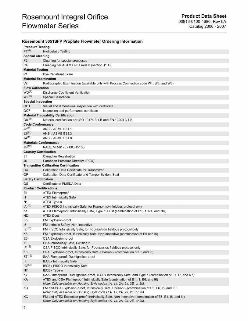
Pressure Testing
P1(8) Hydrostatic Testing
Special Cleaning
P2 Cleaning for special processes
PA Cleaning per ASTM G93 Level D (section 11.4)
Material Testing
V1 Dye Penetrant Exam
Material Examination
V2 Radiographic Examination (available only with Process Connection code W1, W3, and W6)
Flow Calibration
WD(9) Discharge Coefficient Verification
WZ(9) Special Calibration
Special Inspection
QC1 Visual and dimensional inspection with certificate
QC7 Inspection and performance certificate
Material Traceability Certification
Q8(10) Material certification per ISO 10474 3.1.B and EN 10204 3.1.B
Code Conformance
J2(11) ANSI / ASME B31.1
J3(11) ANSI / ASME B31.3
J4(11) ANSI / ASME B31.8
Materials Conformance
J5(12) NACE MR-0175 / ISO 15156
Country Certification
J1 Canadian Registration
J6 European Pressure Directive (PED)
Transmitter Calibration Certification
Q4 Calibration Data Certificate for Transmitter
QP Calibration Data Certificate and Tamper Evident Seal
Safety Certification
QS Certificate of FMEDA Data
Product Certifications
E1 ATEX Flameproof
I1 ATEX Intrinsically Safe
N1 ATEX Type n
IA(13) ATEX FISCO Intrinsically Safe; for FOUNDATION fieldbus protocol only
K1 ATEX Flameproof, Intrinsically Safe, Type n, Dust (combination of E1, I1, N1, and ND)
ND ATEX Dust
E5 FM Explosion-proof
I5 FM Intrinsic Safety, Non-incendive
IE(13) FM FISCO Intrinsically Safe; for FOUNDATION fieldbus protocol only
K5 FM Explosion-proof, Intrinsically Safe, Non-incendive (combination of E5 and I5)
E6 CSA Explosion-proof
I6 CSA Intrinsically Safe, Division 2
IF(13) CSA FISCO Intrinsically Safe; for FOUNDATION fieldbus protocol only
K6 CSA Explosion-proof, Intrinsically Safe, Division 2 (combination of E6 and I6)
E7(13) SAA Flameproof, Dust Ignition-proof
I7 IECEx Intrinsically Safe
IG(13) IECEx FISCO Intrinsically Safe
N7 IECEx Type n
K7 SAA Flameproof, Dust Ignition-proof, IECEx Intrinsically Safe, and Type n (combination of E7, I7, and N7)
KA ATEX and CSA Flameproof, Intrinsically Safe (combination of E1, I1, E6, and I6)
Note: Only available on Housing Style codes 1A, 1J, 2A, 2J, 2E, or 2M.
KB FM and CSA Explosion-proof, Intrinsically Safe, Division 2 (combination of E5, E6, I5, and I6)
Note: Only available on Housing Style codes 1A, 1J, 2A, 2J, 2E, or 2M.
KC FM and ATEX Explosion-proof, Intrinsically Safe, Non-incendive (combination of E5, E1, I5, and I1)
Note: Only available on Housing Style codes 1A, 1J, 2A, 2J, 2E, or 2M.
Rosemount 3051SFP Proplate Flowmeter Ordering Information
Product Data Sheet00813-0100-4686, Rev LA
Catalog 2006 - 2007
Rosemount Integral Orifice
Flowmeter Series
KD FM, CSA, and ATEX Explosion-proof, Intrinsically Safe (combination of E5, I5, E6, I6, E1, and I1)
Note: Only available on Housing Style codes 1A, 1J, 2A, 2J, 2E, or 2M.
Alternative Transmitter Material of Construction
L1 Inert Sensor Fill Fluid
L2 Graphite-filled Teflon® (PTFE) o-ring
LA Inert sensor fill fluid and graphite-filled Teflon (PTFE) o-ring
Display(14)
M5 PlantWeb LCD display
M7(6)(15) Remote mount LCD display and interface, PlantWeb housing, no cable, SST bracket
M8(6)(15) Remote mount LCD display and interface, PlantWeb housing, 50 foot cable, SST bracket
M9(6)(15) Remote mount LCD display and interface, PlantWeb housing, 100 foot cable, SST bracket
Terminal Blocks
T1(14) Transient terminal block
T2(16) Terminal block with WAGO® spring clamp terminals
T3(16) Transient terminal block with WAGO spring clamp terminals
PlantWeb Control Functionality
A01(17) FOUNDATION fieldbus Advanced Control Function Block Suite
PlantWeb Diagnostic Functionality
D01(17) FOUNDATION fieldbus Diagnostics Suite
DA1(18) HART Diagnostics Suite
PlantWeb Enhanced Measurement Functionality
H01(17)(19) Fully Compensated Mass Flow Block
Alarm Limits
C4(20) NAMUR alarm and saturation signal levels, high alarm
C5(20) NAMUR alarm and saturation signal levels, low alarm
C6(6)(20) Custom alarm and saturation signal levels, high alarm
Note: Requires option code C1, custom software configuration. A Configuration Data Sheet must be completed, see page 38.
C7(6)(20) Custom alarm and saturation signal levels, low alarm
Note: Requires option code C1, custom software configuration. A Configuration Data Sheet must be completed, see page 38.
C8(20) Low alarm (standard Rosemount alarm and saturation signal levels)
Special Configuration (Hardware)
D1(20) Hardware Adjustment (zero, span, alarm, security)
D4 External ground screw
DA(20) Hardware adjustment (zero, span, security) and external ground screw
Conduit Electrical Connector
GE (21) M12, 4-pin, Male Connector (eurofast®)
GM(21) A size Mini, 4-pin, Male Connector (minifast®)
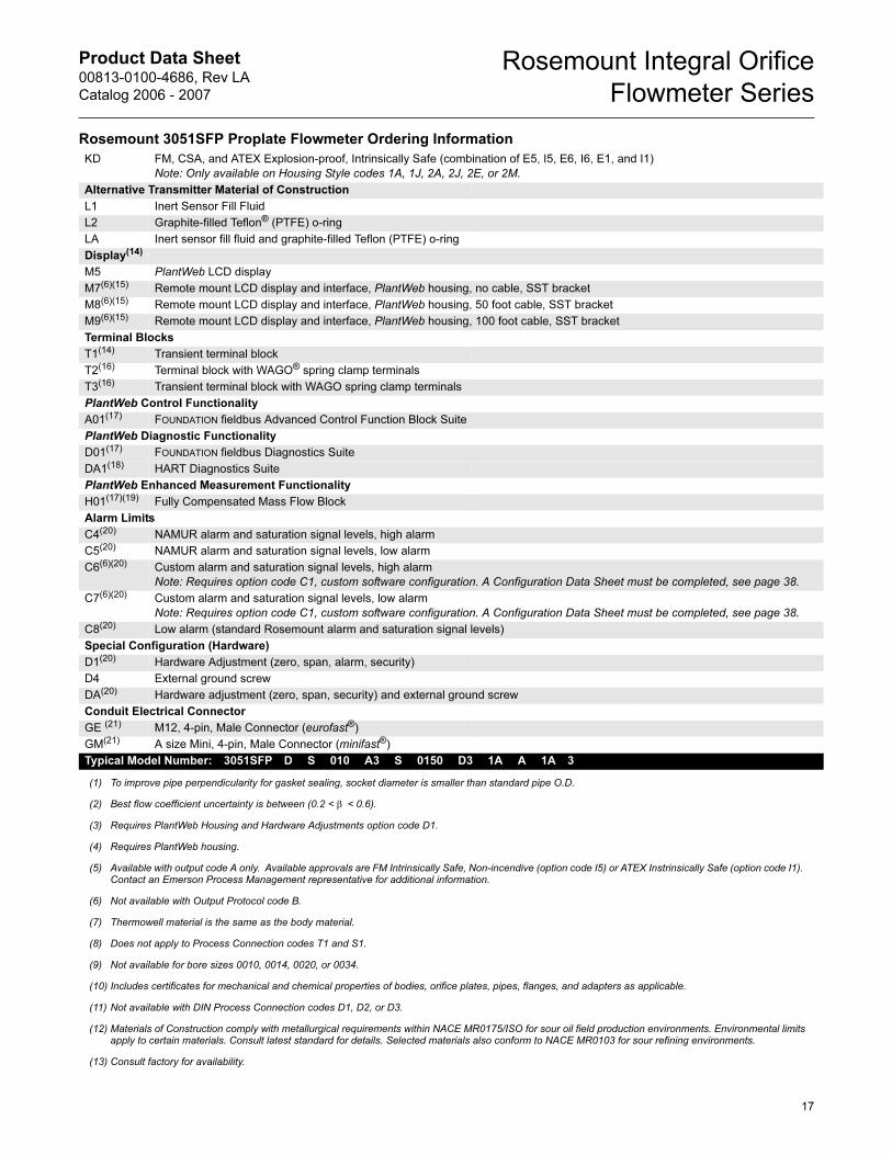
Typical Model Number: 3051SFP D S 010 A3 S 0150 D3 1A A 1A 3
(1) To improve pipe perpendicularity for gasket sealing, socket diameter is smaller than standard pipe O.D.
(2) Best flow coefficient uncertainty is between (0.2 < β < 0.6).
(3) Requires PlantWeb Housing and Hardware Adjustments option code D1.
(4) Requires PlantWeb housing.
(5) Available with output code A only. Available approvals are FM Intrinsically Safe, Non-incendive (option code I5) or ATEX Instrinsically Safe (option code I1). Contact an Emerson Process Management representative for additional information.
(6) Not available with Output Protocol code B.
(7) Thermowell material is the same as the body material.
(8) Does not apply to Process Connection codes T1 and S1.
(9) Not available for bore sizes 0010, 0014, 0020, or 0034.
(10) Includes certificates for mechanical and chemical properties of bodies, orifice plates, pipes, flanges, and adapters as applicable.
(11) Not available with DIN Process Connection codes D1, D2, or D3.
(12) Materials of Construction comply with metallurgical requirements within NACE MR0175/ISO for sour oil field production environments. Environmental limits apply to certain materials. Consult latest standard for details. Selected materials also conform to NACE MR0103 for sour refining environments.
(13) Consult factory for availability.
Rosemount 3051SFP Proplate Flowmeter Ordering Information
17
Product Data Sheet00813-0100-4686, Rev LA
Catalog 2006 - 2007
Rosemount Integral Orifice
Flowmeter Series
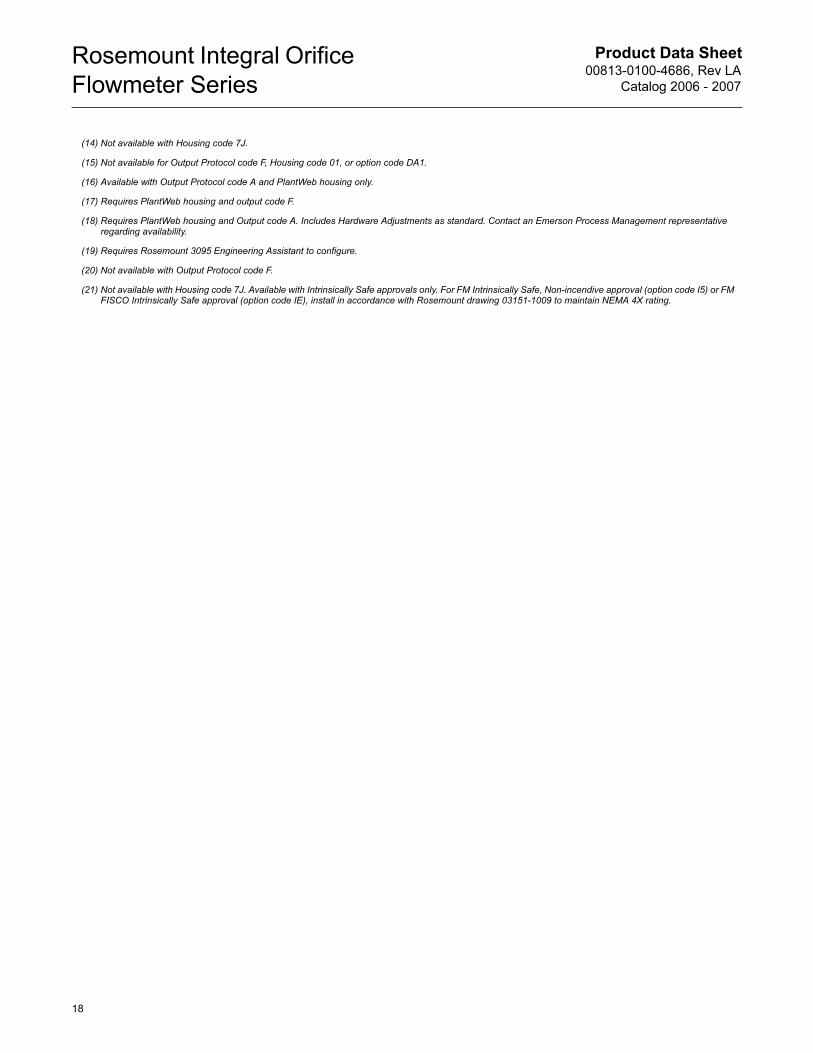
(14) Not available with Housing code 7J.
(15) Not available for Output Protocol code F, Housing code 01, or option code DA1.
(16) Available with Output Protocol code A and PlantWeb housing only.
(17) Requires PlantWeb housing and output code F.
(18) Requires PlantWeb housing and Output code A. Includes Hardware Adjustments as standard. Contact an Emerson Process Management representative regarding availability.
(19) Requires Rosemount 3095 Engineering Assistant to configure.
(20) Not available with Output Protocol code F.
(21) Not available with Housing code 7J. Available with Intrinsically Safe approvals only. For FM Intrinsically Safe, Non-incendive approval (option code I5) or FM FISCO Intrinsically Safe approval (option code IE), install in accordance with Rosemount drawing 03151-1009 to maintain NEMA 4X rating.
18
Product Data Sheet00813-0100-4686, Rev LA
Catalog 2006 - 2007
Rosemount Integral Orifice
Flowmeter Series
Rosemount 3095MFP Mass Proplate Flowmeter
SPECIFICATIONS
Performance
Repeatability
±0.1%
Line Sizes
• 1/2-in. (15 mm)
• 1-in. (25 mm)
• 11/2-in. (40 mm)
Output
Two-wire 4–20 mA, user-selectable for DP, AP, GP, PT, mass flow,
or totalized flow. Digital HART protocol superimposed on 4–20 mA
signal, available to any host that conforms to the HART protocol.
Performance Statement Assumptions
• Measured pipe I.D
• Electronics are trimmed for optimum flow accuracy
Sizing
Contact a Emerson Process Management sales representative for
assistance. A “Configuration Data Sheet” is required prior to order
for application verification.
Functional
Service
• Liquid
• Gas
• Steam
Power Supply
4–20 mA option
• External power supply required. Standard transmitter
(4–20 mA) operates on 11 to 55 v dc with no load
Process Temperature Limits
Direct Mount Electronics
• –40 to 450 °F (–40 to 232 °C)
Remote Mount Electronics
• –148 to 850 °F (–100 to 454 °C)(1)
Electronics Temperature Limits
Ambient
• –40 to 185 °F (–40 to 85 °C)
• With Integral Mount LCD Display: –4 to 175 °F (–20 to 80 °C)
Storage
• –50 to 230 °F (–46 to 110 °C)
• With Integral Mount LCD Display: –40 to 185 °F (–40 to 85 °C)
Overpressure Limits
• Zero to two times the absolute pressure range with a
maximum of 3626 psia (250 bar).
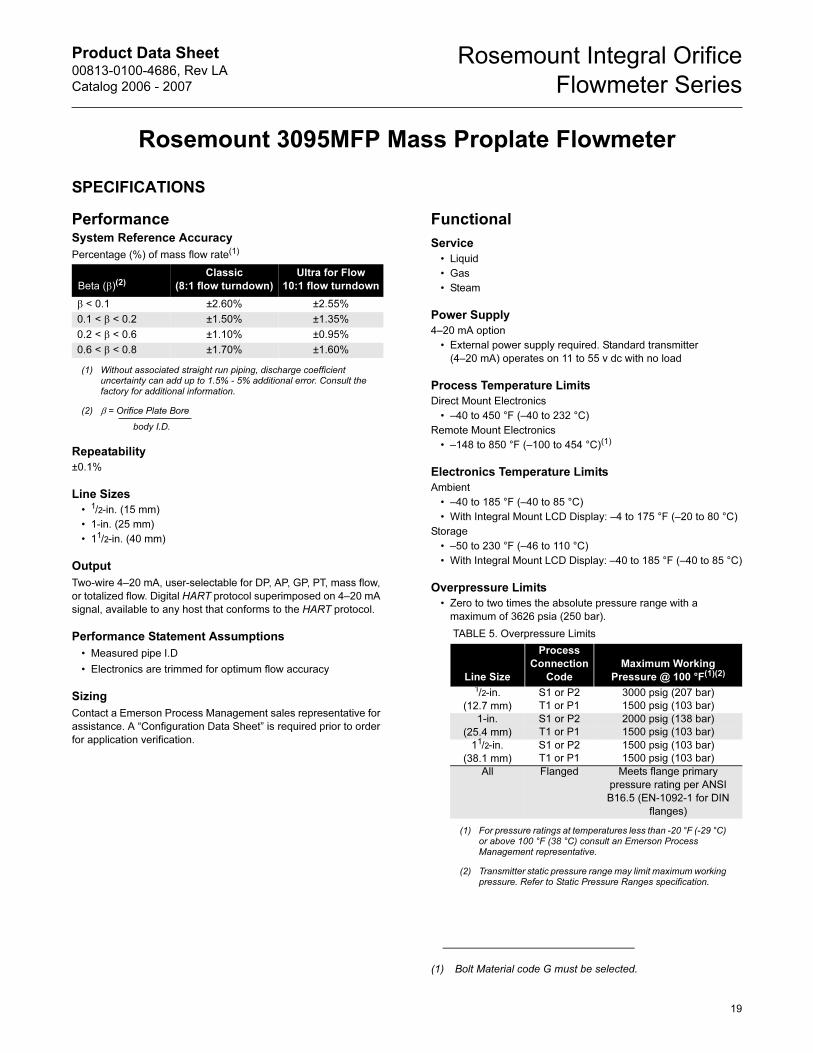
System Reference Accuracy
Percentage (%) of mass flow rate(1)
(1) Without associated straight run piping, discharge coefficient uncertainty can add up to 1.5% - 5% additional error. Consult the factory for additional information.
Beta (β)(2)
(2) β = Orifice Plate Bore
body I.D.
Classic
(8:1 flow turndown)
Ultra for Flow
10:1 flow turndown
β < 0.1 ±2.60% ±2.55%
0.1 < β < 0.2 ±1.50% ±1.35%
0.2 < β < 0.6 ±1.10% ±0.95%
0.6 < β < 0.8 ±1.70% ±1.60%
(1) Bolt Material code G must be selected.
TABLE 5. Overpressure Limits
Line Size
Process
Connection
Code
Maximum Working
Pressure @ 100 °F(1)(2)
(1) For pressure ratings at temperatures less than -20 °F (-29 °C) or above 100 °F (38 °C) consult an Emerson Process Management representative.
(2) Transmitter static pressure range may limit maximum working pressure. Refer to Static Pressure Ranges specification.
1/2-in.
(12.7 mm)
S1 or P2 3000 psig (207 bar)
T1 or P1 1500 psig (103 bar)
1-in.
(25.4 mm)
S1 or P2 2000 psig (138 bar)
T1 or P1 1500 psig (103 bar)
11/2-in.
(38.1 mm)
S1 or P2 1500 psig (103 bar)
T1 or P1 1500 psig (103 bar)
All Flanged Meets flange primary
pressure rating per ANSI
B16.5 (EN-1092-1 for DIN
flanges)
19
Product Data Sheet00813-0100-4686, Rev LA
Catalog 2006 - 2007
Rosemount Integral Orifice
Flowmeter Series
Static Pressure Limits
Operates within specification between static pressures of 0.5 psia
(0.03 bar-A) and the URL of the static pressure sensor.
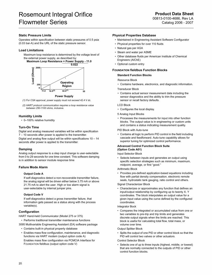
Load Limitations
Maximum loop resistance is determined by the voltage level of
the external power supply, as described by:
Humidity Limits
• 0–100% relative humidity
Turn-On Time
Digital and analog measured variables will be within specification
7 – 10 seconds after power is applied to the transmitter.
Digital and analog flow output will be within specifications 10 – 14
seconds after power is applied to the transmitter.
Damping
Analog output response to a step input change is user-selectable
from 0 to 29 seconds for one time constant. This software damping
is in addition to sensor module response time
Failure Mode Alarm
Output Code A
If self-diagnostics detect a non-recoverable transmitter failure,
the analog signal will be driven either below 3.75 mA or above
21.75 mA to alert the user. High or low alarm signal is
user-selectable by internal jumper pins.
Output Code V
If self-diagnostics detect a gross transmitter failure, that
information gets passed as a status along with the process
variable(s).
Configuration
HART Hand-held Communicator (Model 275 or 375)
• Performs traditional transmitter maintenance functions
3095 Multivariable Engineering Assistant (EA) software package
• Contains built-in physical property database
• Enables mass flow configuration, maintenance, and diagnostic
functions via HART modem (output option code A)
Enables mass flow configuration via PCMCIA Interface for
FOUNDATION fieldbus (output option code V)
Physical Properties Database
• Maintained in Engineering Assistant Software Configurator
• Physical properties for over 110 fluids
• Natural gas per AGA
• Steam and water per ASME
• Other database fluids per American Institute of Chemical
Engineers (AIChE)
• Optional custom entry
FOUNDATION fieldbus Function Blocks
Standard Function Blocks
Resource Block
• Contains hardware, electronics, and diagnostic information.
Transducer Block
• Contains actual sensor measurement data including the
sensor diagnostics and the ability to trim the pressure
sensor or recall factory defaults.
LCD Block
• Configures the local display.
5 Analog Input Blocks
• Processes the measurements for input into other function
blocks. The output value is in engineering or custom units
and contains a status indicating measurement quality.
PID Block with Auto-tune
• Contains all logic to perform PID control in the field including
cascade and feedforward. Auto-tune capability allows for
superior tuning for optimized control performance.
Advanced Control Function Block Suite
(Option Code A01)
Input Selector Block
• Selects between inputs and generates an output using
specific selection strategies such as minimum, maximum,
midpoint, average, or first “good.”
Arithmetic Block
• Provides pre-defined application-based equations including
flow with partial density compensation, electronic remote
seals, hydrostatic tank gauging, ratio control and others.
Signal Characterizer Block
• Characterizes or approximates any function that defines an
input/output relationship by configuring up to twenty X, Y
coordinates. The block interpolates an output value for a
given input value using the curve defined by the configured
coordinates.
Integrator Bock
• Compares the integrated or accumulated value from one or
two variables to pre-trip and trip limits and generates
discrete output signals when the limits are reached. This
block is useful for calculating total flow, total mass, or
volume over time.
Output Splitter Block
• Splits the output of one PID or other control block so that the
PID will control two valves or other actuators.
Control Selector Block
• Selects one of up to three inputs (highest, middle, or lowest)
that are normally connected to the outputs of PID or other
control function blocks.
Lo
ad
(O
hm
s)
0
11.0 42.4(1)
55
Operating
Region
(1) For CSA approval, power supply must not exceed 42.4 V dc.
(2) HART protocol communication requires a loop resistance value between 250-1100 ohms, inclusive.
Power Supply
250
16.5(2)
Maximum Loop Resistance = Power Supply - 11.00.022
2000
20
Product Data Sheet00813-0100-4686, Rev LA
Catalog 2006 - 2007
Rosemount Integral Orifice
Flowmeter Series
Physical
Temperature Measurement
Remote RTD
• 100 Ohm platinum with 1/2-in. NPT nipple and union (078
series with Rosemount 644 housing)
• Standard RTD cable is shielded armored cable, length is12
feet (3.66 m)
• Remote RTD material is SST
Thermowell
• 1/2-in. x 1/2-in. NPT, 316 SST
Electrical Considerations1/2–14 NPT, G1/2, and CM20 conduit. HART interface connections
permanently fixed to terminal block
Material of Construction
Orifice Plate
• 316/316L SST
• Hastelloy C-276
• Monel 400
Body
• 316 SST (CF8M), material per ASTM A351
• Hastelloy C-276 (CW12MW), material per ASTM A494
Flange and Pipe Material (If Applicable)
• A312 Gr 316/316L, B622 UNS N10276
• Flange pressure limits are per ANSI B16.5
• Flange face finish per ANSI B16.5, 125 to 250 RMS
Body Bolts/Studs
• ASTM A193 Gr B8M studs
• SAE J429 Gr 8 bolts (meets or exceeds ASTM A193 B7
requirements) for body bolt/stud material option code G for
high temperatures.
Transmitter Connection Studs
• ASTM A193 Gr B8M studs
Gaskets/O-rings
• Glass filled Teflon® (PTFE)
• Optional high temperature Inconel® X-750
• Gaskets and o-rings must be replaced each time the
3095MFP is disassembled for installation or maintenance.
Orifice Type
Square edged—orifice bore size
• 0.066-in and larger
Quadrant edged—orifice bore size (for 1/2-in. line size only)
• 0.034-in
• 0.020-in
• 0.014-in
• 0.010-in
NOTE
Integral Orifice bodies contain corner tapped pressure ports.
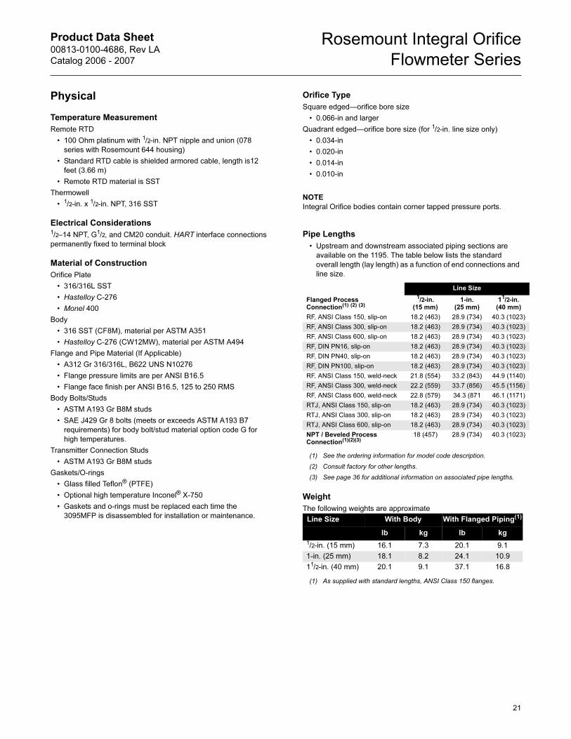
Pipe Lengths
• Upstream and downstream associated piping sections are
available on the 1195. The table below lists the standard
overall length (lay length) as a function of end connections and
line size.
Weight
The following weights are approximate
Line Size
Flanged Process Connection(1) (2) (3)
(1) See the ordering information for model code description.
(2) Consult factory for other lengths.
(3) See page 36 for additional information on associated pipe lengths.
1/2-in. (15 mm)
1-in. (25 mm)
11/2-in. (40 mm)
RF, ANSI Class 150, slip-on 18.2 (463) 28.9 (734) 40.3 (1023)
RF, ANSI Class 300, slip-on 18.2 (463) 28.9 (734) 40.3 (1023)
RF, ANSI Class 600, slip-on 18.2 (463) 28.9 (734) 40.3 (1023)
RF, DIN PN16, slip-on 18.2 (463) 28.9 (734) 40.3 (1023)
RF, DIN PN40, slip-on 18.2 (463) 28.9 (734) 40.3 (1023)
RF, DIN PN100, slip-on 18.2 (463) 28.9 (734) 40.3 (1023)
RF, ANSI Class 150, weld-neck 21.8 (554) 33.2 (843) 44.9 (1140)
RF, ANSI Class 300, weld-neck 22.2 (559) 33.7 (856) 45.5 (1156)
RF, ANSI Class 600, weld-neck 22.8 (579) 34.3 (871 46.1 (1171)
RTJ, ANSI Class 150, slip-on 18.2 (463) 28.9 (734) 40.3 (1023)
RTJ, ANSI Class 300, slip-on 18.2 (463) 28.9 (734) 40.3 (1023)
RTJ, ANSI Class 600, slip-on 18.2 (463) 28.9 (734) 40.3 (1023)
NPT / Beveled Process Connection(1)(2)(3)
18 (457) 28.9 (734) 40.3 (1023)
Line Size With Body With Flanged Piping(1)
(1) As supplied with standard lengths, ANSI Class 150 flanges.
lb kg lb kg
1/2-in. (15 mm) 16.1 7.3 20.1 9.1
1-in. (25 mm) 18.1 8.2 24.1 10.9
11/2-in. (40 mm) 20.1 9.1 37.1 16.8
21
Product Data Sheet00813-0100-4686, Rev LA
Catalog 2006 - 2007
Rosemount Integral Orifice
Flowmeter Series
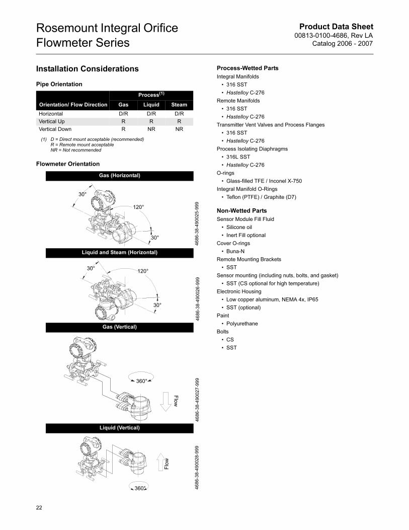
Installation Considerations
Pipe Orientation
Flowmeter Orientation
Process-Wetted Parts
Integral Manifolds
• 316 SST
• Hastelloy C-276
Remote Manifolds
• 316 SST
• Hastelloy C-276
Transmitter Vent Valves and Process Flanges
• 316 SST
• Hastelloy C-276
Process Isolating Diaphragms
• 316L SST
• Hastelloy C-276
O-rings
• Glass-filled TFE / Inconel X-750
Integral Manifold O-Rings
• Teflon (PTFE) / Graphite (D7)
Non-Wetted Parts
Sensor Module Fill Fluid
• Silicone oil
• Inert Fill optional
Cover O-rings
• Buna-N
Remote Mounting Brackets
• SST
Sensor mounting (including nuts, bolts, and gasket)
• SST (CS optional for high temperature)
Electronic Housing
• Low copper aluminum, NEMA 4x, IP65
• SST (optional)
Paint
• Polyurethane
Bolts
• CS
• SST
Orientation/ Flow Direction
Process(1)
(1) D = Direct mount acceptable (recommended)R = Remote mount acceptableNR = Not recommended
Gas Liquid Steam
Horizontal D/R D/R D/R
Vertical Up R R R
Vertical Down R NR NR
Gas (Horizontal)
Liquid and Steam (Horizontal)
Gas (Vertical)
Liquid (Vertical)
30°
30°
120°
4686-38-490025-999
30°
30°
120°
4686-38-490026-999
360°
Flow
4686-38-490027-999
360°
Flow
4686-38-490028-999
22
Product Data Sheet00813-0100-4686, Rev LA
Catalog 2006 - 2007
Rosemount Integral Orifice
Flowmeter Series
PRODUCT CERTIFICATIONS
Rosemount 3095 with HART
European Directive InformationThe EC declaration of conformity for all applicable European
directives for this product can be found on the Rosemount website
at www.rosemount.com. A hard copy may be obtained by
contacting our local sales office.
ATEX Directive (94/9/EC)Emerson Process Management complies with the ATEX Directive.
European Pressure Equipment Directive (PED)
(97/23/EC)3095M_2/3,4/D Flow Transmitters — QS Certificate of Assessment - EC No. PED-H-20Module H Conformity Assessment
All other 3095_ Transmitters/Level Controller — Sound Engineering Practice
Transmitter Attachments: Process Flange - Manifold —
Sound Engineering Practice
Electro Magnetic Compatibility (EMC)
(89/336/EEC)3095MV Flow Transmitters
— EN 50081-1: 1992; EN 50082-2:1995; EN 61326-1:1997 – Industrial
Ordinary Location Certification for Factory
MutualAs standard, the transmitter has been examined and tested to
determine that the design meets basic electrical, mechanical, and
fire protection requirements by FM, a nationally recognized testing
laboratory (NRTL) as accredited by the Federal Occupational
Safety and Health Administration (OSHA).
Hazardous Locations Certifications
North American CertificationsFM Approvals
E5 Explosion Proof for Class I, Division 1, Groups B, C, and D.
Dust-Ignition Proof for Class II/Class III, Division 1, Groups
E, F, and G. Enclosure type NEMA 4X. Factory Sealed.
Provides nonincendive RTD connections for Class I, Division
2, Groups A, B, C, and D.
I5 Intrinsically Safe for use in Class I, II and III, Division 1,
Groups A, B, C, D, E, F, and G hazardous outdoor locations.
Non-incendive for Class I, Division 2, Groups A, B, C, and D.
Temperature Code T4. Factory Sealed.
For input parameters and installation see control drawing
03095-1020.
Canadian Standards Association (CSA)
E6 Explosion Proof for Class I, Division 1, Groups B, C, and D.
Dust-Ignition Proof for Class II/Class III, Division 1, Groups
E, F, and G. CSA enclosure Type 4X suitable for indoor and
outdoor hazardous locations. Provides nonincendive RTD
connection for Class I, Division 2, Groups A, B, C, and
D.Factory Sealed. Install in accordance with Rosemount
Drawing 03095-1024. Approved for Class I, Division 2,
Groups A, B, C, and D.
I6 Intrinsically Safe for Class I, Division 1, Groups A, B, C, and
D. when installed in accordance with Rosemount drawing
03095-1021. Temperature Code T3C.
For input parameters and installation see control drawing
03095-1021.
European CertificationsI1 ATEX Intrinsic Safety
Certificate Number: BAS98ATEX1359X II 1 G
EEx ia IIC T5 (Tamb = –45 °C to 40 °C)
EEx ia IIC T4 (Tamb = –45 °C to 70 °C)
1180
Special Conditions for Safe Use
The 3095, when fitted with the transient terminal block
(order code B), are not capable of withstanding the 500 volts
insulation test required by EN50 020, Clause 6.4.12 (1994).
This condition must be accounted for during installation.
N1 ATEX Type N
Certificate Number: BAS98ATEX3360X II 3 G
EEx nL IIC T5 (Tamb = –45 °C to 40 °C)
EEx nL IIC T4 (Tamb = –45 °C to 70 °C)
Ui = 55V
The apparatus is designed for connection to a remote
temperature sensor such as a resistance temperature
detection (RTD)
Special Conditions for Safe Use
TABLE 6. Connection Parameters (Power/Signal Terminals)
Ui = 30V
Ii = 200 mA
Pi = 1.0 W
Ci = 0.012 µF
Li = 0
TABLE 7. Temperature Sensor Connection Parameters
Uo = 30V
Io = 19 mA
Po = 140 mW
Ci = 0.002 µF
Li = 0
TABLE 8. Temp Sensor Terminals Connection Parameters
Co = 0.066 �F Gas Group IIC
Co = 0.560 �F Gas Group IIB
Co = 1.82 �F Gas Group IIA
Lo = 96 mH Gas Group IIC
Lo = 365 mH Gas Group IIB
Lo = 696 mH Gas Group IIA
Lo/Ro = 247 �H/ohm Gas Group IIC
Lo/Ro = 633 �H/ohm Gas Group IIB
Lo/Ro= 633 �H/ohm Gas Group IIA
23
Product Data Sheet00813-0100-4686, Rev LA
Catalog 2006 - 2007
Rosemount Integral Orifice
Flowmeter Series
The 3095, when fitted with the transient terminal block
(order code B), are not capable of withstanding the 500 volts
insulation test required by EN50 021, Clause 9.1 (1995).
This condition must be accounted for during installation.
E1 ATEX Flameproof
Certificate Number: KEMA02ATEX2320X II 1/2 G
EEx d IIC T5 (-50°C ≤ Tamb ≤ 80°C)
T6 (-50°C ≤ Tamb ≤ 65°C)
1180
Special Conditions for Safe Use (x):
The device contains a thin wall diaphragm. Installation,
maintenance, and use shall take into account the
environmental conditions to which the diaphragm will be
subjected. the manufacturer’s instructions fro installation
and maintenance shall be followed in detail to assure safety
during its expected lifetime.
ND ATEX Dust
Certificate Number: KEMA02ATEX2321 II 1 D
V = 55 Vdc MAX
I = 23 mA MAX
IP66
1180
Combinations of CertificationsStainless steel certification tag is provided when optional approval
is specified. Once a device labeled with multiple approval types is
installed, it should not be reinstalled using any other approval
types. Permanently mark the approval label to distinguish it from
unused approval types.
K5 E5 and I5 combination
K6 E6 and I6 combination
K1 I1, N1, E1, and ND combination
Rosemount 3095 with Fieldbus
European Directive Information
The EC declaration of conformity for all applicable European
directives for this product can be found on the Rosemount website
at www.rosemount.com. A hard copy may be obtained by
contacting our local sales office.
ATEX Directive (94/9/EC)
Emerson Process Management complies with the ATEX Directive.
European Pressure Equipment Directive (PED)
(97/23/EC)
3095F_2/3,4/D and 3095M_2/3,4/D Flow Transmitters
— QS Certificate of Assessment - EC No. PED-H-20
Module H Conformity Assessment
All other 3095_ Transmitters/Level Controller
— Sound Engineering Practice
Transmitter Attachments: Process Flange - Manifold
— Sound Engineering Practice
Primary Elements, Flowmeter
— See appropriate Primary Element QIG
Electro Magnetic Compatibility (EMC) (89/336/EEC)
3095 Flow Transmitters
— EN 50081-1: 1992; EN 50082-2:1995; EN 61326-1:1997 –
Industrial
Ordinary Location Certification for Factory Mutual
As standard, the transmitter has been examined and tested to
determine that the design meets basic electrical, mechanical, and
fire protection requirements by FM, a nationally recognized testing
laboratory (NRTL) as accredited by the Federal Occupational
Safety and Health Administration (OSHA).
Rosemount 3095 Fieldbus Hazardous Locations Certifications
North American Certifications
FM Approvals
E5 Explosion Proof for Class I, Division 1, Groups B, C, and D.
Dust-Ignition Proof for Class II/Class III, Division 1, Groups
E, F, and G. Enclosure type NEMA 4X. Factory Sealed.
Provides nonincendive RTD connections for Class I,
Division 2, Groups A, B, C, and D.
I5 Intrinsically Safe for use in Class I, II and III, Division 1,
Groups A, B, C, D, E, F, and G hazardous outdoor locations.
Non-incendive for Class I, Division 2, Groups A, B, C, and D.
Temperature Code T4. Factory Sealed.
For input parameters and installation see control drawing
03095-1020.
IE FISCO for use in Class I, II and III, Division 1, Groups A, B,
C, D, E, F, and G hazardous outdoor locations. Temperature
Code T4. Factory Sealed.
For input parameters and installation see control drawing
03095-1020.
Combinations of Certifications
Stainless steel certification tag is provided when optional approval
is specified. Once a device labeled with multiple approval types is
installed, it should not be reinstalled using any other approval
types. Permanently mark the approval label to distinguish it from
unused approval types.
K5 E5 and I5 combination
Canadian Standards Association (CSA)
IF CSA FISCO Intrinsically Safe; for FOUNDATION fieldbus
protocol only
European Certifications
IA ATEX FISCO Intrinsically Safe; for FOUNDATION fieldbus
protocol only
Australian Certifications
IG IECEx FISCO Intrinsic Safety
24
Product Data Sheet00813-0100-4686, Rev LA
Catalog 2006 - 2007
Rosemount Integral Orifice
Flowmeter Series
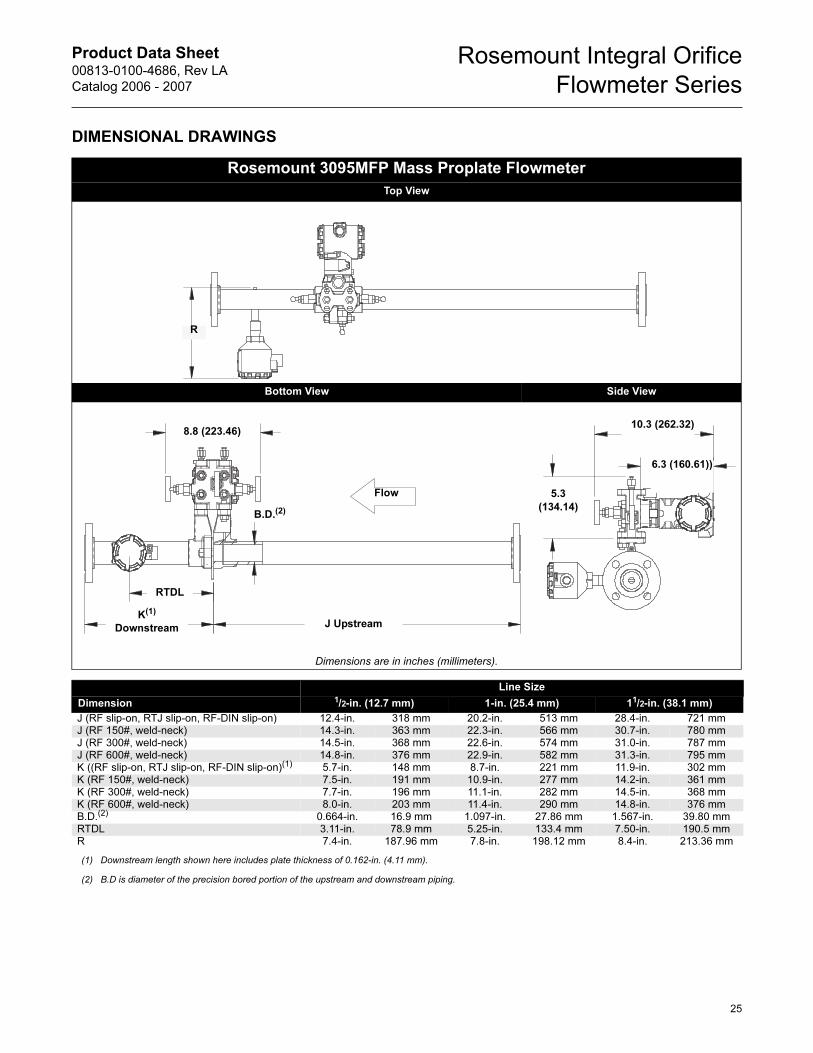
DIMENSIONAL DRAWINGS
Rosemount 3095MFP Mass Proplate Flowmeter
Top View
Bottom View Side View
Dimensions are in inches (millimeters).
Line Size
Dimension 1/2-in. (12.7 mm) 1-in. (25.4 mm) 11/2-in. (38.1 mm)
J (RF slip-on, RTJ slip-on, RF-DIN slip-on) 12.4-in. 318 mm 20.2-in. 513 mm 28.4-in. 721 mmJ (RF 150#, weld-neck) 14.3-in. 363 mm 22.3-in. 566 mm 30.7-in. 780 mmJ (RF 300#, weld-neck) 14.5-in. 368 mm 22.6-in. 574 mm 31.0-in. 787 mmJ (RF 600#, weld-neck) 14.8-in. 376 mm 22.9-in. 582 mm 31.3-in. 795 mmK ((RF slip-on, RTJ slip-on, RF-DIN slip-on)(1) 5.7-in. 148 mm 8.7-in. 221 mm 11.9-in. 302 mmK (RF 150#, weld-neck) 7.5-in. 191 mm 10.9-in. 277 mm 14.2-in. 361 mmK (RF 300#, weld-neck) 7.7-in. 196 mm 11.1-in. 282 mm 14.5-in. 368 mmK (RF 600#, weld-neck) 8.0-in. 203 mm 11.4-in. 290 mm 14.8-in. 376 mmB.D.(2) 0.664-in. 16.9 mm 1.097-in. 27.86 mm 1.567-in. 39.80 mmRTDL 3.11-in. 78.9 mm 5.25-in. 133.4 mm 7.50-in. 190.5 mmR 7.4-in. 187.96 mm 7.8-in. 198.12 mm 8.4-in. 213.36 mm
(1) Downstream length shown here includes plate thickness of 0.162-in. (4.11 mm).
(2) B.D is diameter of the precision bored portion of the upstream and downstream piping.
R
Flow
8.8 (223.46)
J UpstreamK(1)
Downstream
RTDL
5.3
(134.14)
10.3 (262.32)
6.3 (160.61))
B.D.(2)
25
Product Data Sheet00813-0100-4686, Rev LA
Catalog 2006 - 2007
Rosemount Integral Orifice
Flowmeter Series
26
ORDERING INFORMATION
Rosemount 3095MFP Mass Proplate Flowmeter Ordering Information
Model Product Description
3095MFP Mass Proplate Flowmeter
Code Body Material
S 316 SST
H Hastelloy C-276
Code Line Size
005 1/2-in. (15 mm)
010 1-in. (25 mm)
015 11/2-in. (40 mm)
Code Process Connection
T1 NPT Female Body (not available with remote thermowell and RTD, requires Temperature Sensor code N)
S1(1) Socket Weld Body (not available with remote thermowell and RTD, requires Temperature Sensor code N)
P1 Pipe Ends: NPT threaded
P2 Pipe Ends: Beveled
A1 Pipe Ends: Flanged, RF, ANSI Class 150, slip-on
A3 Pipe Ends: Flanged, RF, ANSI Class 300, slip-on
A6 Pipe Ends: Flanged, RF, ANSI Class 600, slip-on
D1 Pipe Ends: Flanged, RF, DIN PN16, slip-on
D2 Pipe Ends: Flanged, RF, DIN PN40, slip-on
D3 Pipe Ends: Flanged, RF, DIN PN100, slip-on
W1 Pipe Ends: Flanged, RF, ANSI Class 150, weld-neck
W3 Pipe Ends: Flanged, RF, ANSI Class 300, weld-neck
W6 Pipe Ends: Flanged, RF, ANSI Class 600, weld-neck
R1 Pipe Ends: Flanged, RTJ, ANSI Class 150, slip-on
R3 Pipe Ends: Flanged, RTJ, ANSI Class 300, slip-on
R6 Pipe Ends: Flanged, RTJ, ANSI Class 600, slip-on
P9 Special process connections
Code Orifice Plate Material
S 316 SST
H Hastelloy C-276
M Monel
Code Bore Size Option
0010 0.010-in. (0.25 mm) for 1/2-in. pipe
0014 0.014-in. (0.36 mm) for 1/2-in. pipe
0020 0.020-in. (0.51 mm) for 1/2-in. pipe
0034 0.034-in. (0.86 mm) for 1/2-in. pipe
0066 0.066-in. (1.68 mm) for 1/2-in. pipe
0109 0.109-in. (2.77 mm) for 1/2-in. pipe
0160(2) 0.160-in. (4.06 mm) for 1/2-in. pipe
0196(2) 0.196-in. (4.98 mm) for 1/2-in. pipe
0260(2) 0.260-in. (6.60 mm) for 1/2-in. pipe
0340(2) 0.340-in. (8.64 mm) for 1/2-in. pipe
0150 0.150-in. (3.81 mm) for 1-in. pipe
0250(2) 0.250-in. (6.35 mm) for 1-in. pipe
0345(2) 0.345-in. (8.76 mm) for 1-in. pipe
0500(2) 0.500-in. (12.70 mm) for 1-in. pipe
0630(2) 0.630-in. (16.00 mm) for 1-in. pipe
0800 0.800-in. (20.32 mm) for 1-in. pipe
0295 0.295-in. (7.49 mm) for 11/2-in. pipe
0376(2) 0.376-in. (9.55 mm) for 11/2-in. pipe
0512(2) 0.512-in. (13.00 mm) for 11/2-in. pipe
0748(2) 0.748-in. (19.00 mm) for 11/2-in. pipe
1022 1.022-in. (25.96 mm) for 11/2-in. pipe
1184 1.184-in. (30.07 mm) for 11/2-in. pipe
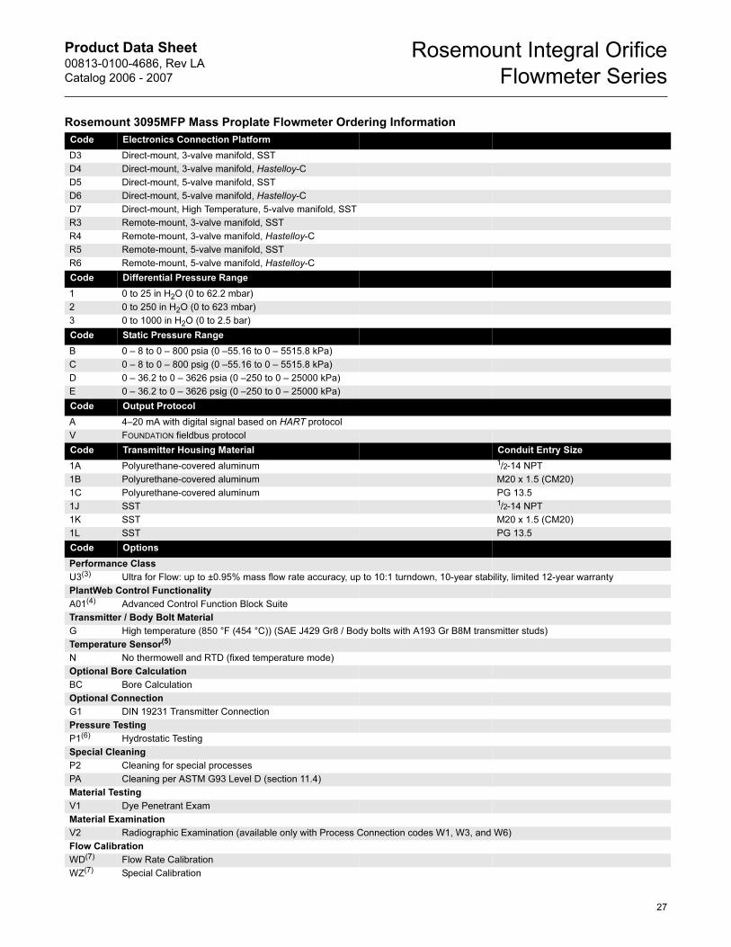
Product Data Sheet00813-0100-4686, Rev LA
Catalog 2006 - 2007
Rosemount Integral Orifice
Flowmeter Series
27
Code Electronics Connection Platform
D3 Direct-mount, 3-valve manifold, SST
D4 Direct-mount, 3-valve manifold, Hastelloy-C
D5 Direct-mount, 5-valve manifold, SST
D6 Direct-mount, 5-valve manifold, Hastelloy-C
D7 Direct-mount, High Temperature, 5-valve manifold, SST
R3 Remote-mount, 3-valve manifold, SST
R4 Remote-mount, 3-valve manifold, Hastelloy-C
R5 Remote-mount, 5-valve manifold, SST
R6 Remote-mount, 5-valve manifold, Hastelloy-C
Code Differential Pressure Range
1 0 to 25 in H2O (0 to 62.2 mbar)
2 0 to 250 in H2O (0 to 623 mbar)
3 0 to 1000 in H2O (0 to 2.5 bar)
Code Static Pressure Range
B 0 – 8 to 0 – 800 psia (0 –55.16 to 0 – 5515.8 kPa)
C 0 – 8 to 0 – 800 psig (0 –55.16 to 0 – 5515.8 kPa)
D 0 – 36.2 to 0 – 3626 psia (0 –250 to 0 – 25000 kPa)
E 0 – 36.2 to 0 – 3626 psig (0 –250 to 0 – 25000 kPa)
Code Output Protocol
A 4–20 mA with digital signal based on HART protocol
V FOUNDATION fieldbus protocol
Code Transmitter Housing Material Conduit Entry Size
1A Polyurethane-covered aluminum 1/2-14 NPT
1B Polyurethane-covered aluminum M20 x 1.5 (CM20)
1C Polyurethane-covered aluminum PG 13.5
1J SST 1/2-14 NPT
1K SST M20 x 1.5 (CM20)
1L SST PG 13.5
Code Options
Performance Class
U3(3) Ultra for Flow: up to ±0.95% mass flow rate accuracy, up to 10:1 turndown, 10-year stability, limited 12-year warranty
PlantWeb Control Functionality
A01(4) Advanced Control Function Block Suite
Transmitter / Body Bolt Material
G High temperature (850 °F (454 °C)) (SAE J429 Gr8 / Body bolts with A193 Gr B8M transmitter studs)
Temperature Sensor(5)
N No thermowell and RTD (fixed temperature mode)
Optional Bore Calculation
BC Bore Calculation
Optional Connection
G1 DIN 19231 Transmitter Connection
Pressure Testing
P1(6) Hydrostatic Testing
Special Cleaning
P2 Cleaning for special processes
PA Cleaning per ASTM G93 Level D (section 11.4)
Material Testing
V1 Dye Penetrant Exam
Material Examination
V2 Radiographic Examination (available only with Process Connection codes W1, W3, and W6)
Flow Calibration
WD(7) Flow Rate Calibration
WZ(7) Special Calibration
Rosemount 3095MFP Mass Proplate Flowmeter Ordering Information
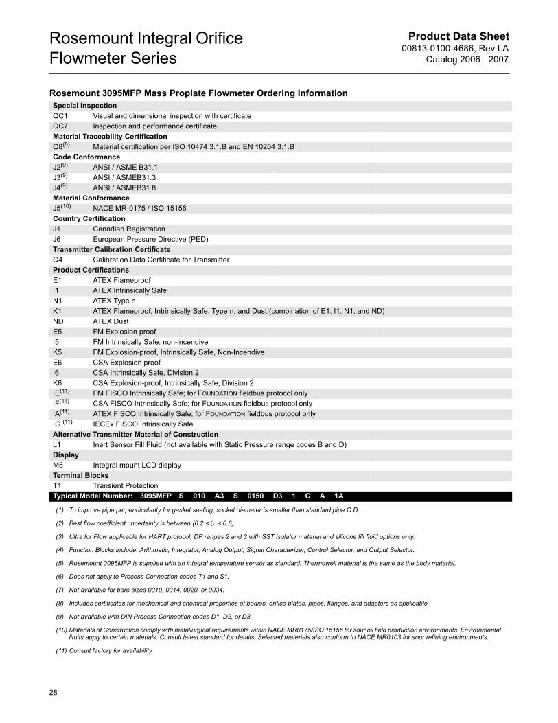
Product Data Sheet00813-0100-4686, Rev LA
Catalog 2006 - 2007
Rosemount Integral Orifice
Flowmeter Series
Special Inspection
QC1 Visual and dimensional inspection with certificate
QC7 Inspection and performance certificate
Material Traceability Certification
Q8(8) Material certification per ISO 10474 3.1.B and EN 10204 3.1.B
Code Conformance
J2(9) ANSI / ASME B31.1
J3(9) ANSI / ASMEB31.3
J4(9) ANSI / ASMEB31.8
Material Conformance
J5(10) NACE MR-0175 / ISO 15156
Country Certification
J1 Canadian Registration
J6 European Pressure Directive (PED)
Transmitter Calibration Certificate
Q4 Calibration Data Certificate for Transmitter
Product Certifications
E1 ATEX Flameproof
I1 ATEX Intrinsically Safe
N1 ATEX Type n
K1 ATEX Flameproof, Intrinsically Safe, Type n, and Dust (combination of E1, I1, N1, and ND)
ND ATEX Dust
E5 FM Explosion proof
I5 FM Intrinsically Safe, non-incendive
K5 FM Explosion-proof, Intrinsically Safe, Non-Incendive
E6 CSA Explosion proof
I6 CSA Intrinsically Safe, Division 2
K6 CSA Explosion-proof, Intrinsically Safe, Division 2
IE(11) FM FISCO Intrinsically Safe; for FOUNDATION fieldbus protocol only
IF(11) CSA FISCO Intrinsically Safe; for FOUNDATION fieldbus protocol only
IA(11) ATEX FISCO Intrinsically Safe; for FOUNDATION fieldbus protocol only
IG (11) IECEx FISCO Intrinsically Safe
Alternative Transmitter Material of Construction
L1 Inert Sensor Fill Fluid (not available with Static Pressure range codes B and D)
Display
M5 Integral mount LCD display
Terminal Blocks
T1 Transient Protection
Typical Model Number: 3095MFP S 010 A3 S 0150 D3 1 C A 1A
(1) To improve pipe perpendicularity for gasket sealing, socket diameter is smaller than standard pipe O.D.
(2) Best flow coefficient uncertainty is between (0.2 < β < 0.6).
(3) Ultra for Flow applicable for HART protocol, DP ranges 2 and 3 with SST isolator material and silicone fill fluid options only.
(4) Function Blocks include: Arithmetic, Integrator, Analog Output, Signal Characterizer, Control Selector, and Output Selector.
(5) Rosemount 3095MFP is supplied with an integral temperature sensor as standard. Thermowell material is the same as the body material.
(6) Does not apply to Process Connection codes T1 and S1.
(7) Not available for bore sizes 0010, 0014, 0020, or 0034.
(8) Includes certificates for mechanical and chemical properties of bodies, orifice plates, pipes, flanges, and adapters as applicable.
(9) Not available with DIN Process Connection codes D1, D2, or D3.
(10) Materials of Construction comply with metallurgical requirements within NACE MR0175/ISO 15156 for sour oil field production environments. Environmental limits apply to certain materials. Consult latest standard for details. Selected materials also conform to NACE MR0103 for sour refining environments.
(11) Consult factory for availability.
Rosemount 3095MFP Mass Proplate Flowmeter Ordering Information
28
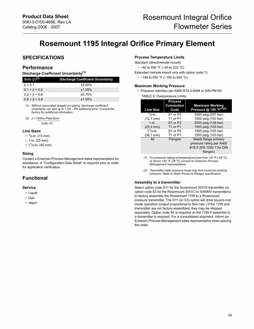
Product Data Sheet00813-0100-4686, Rev LA
Catalog 2006 - 2007
Rosemount Integral Orifice
Flowmeter Series
Rosemount 1195 Integral Orifice Primary Element
SPECIFICATIONS
Performance
Line Sizes
• 1/2-in. (15 mm)
• 1-in. (25 mm)
• 11/2-in. (40 mm)
Sizing
Contact a Emerson Process Management sales representative for
assistance. A “Configuration Data Sheet” is required prior to order
for application verification.
Functional
Service
• Liquid
• Gas
• Vapor
Process Temperature Limits
Standard (direct/remote mount):
• –40 to 450 °F (–40 to 232 °C)
Extended (remote mount only with option code T):
• –148 to 850 °F (–100 to 454 °C)
Maximum Working Pressure
• Pressure retention per ANSI B16.5 600# or DIN PN100
Assembly to a transmitter
Select option code D11 for the Rosemount 3051S transmitter (or
option code S3 for the Rosemount 3051C or 3095MV transmitters)
to factory assemble the Rosemount 1195 to a Rosemount
pressure transmitter. The D11 (or S3) option will drive square-root
mode operation (output proportional to flow rate.) If the 1195 and
transmitter are not factory assembled, they may be shipped
separately. Option code S4 is required on the 1195 if assembly to
a transmitter is required. For a consolidated shipment, inform an
Emerson Process Management sales representative when placing
the order.
Discharge Coefficient Uncertainty(1)
(1) Without associated straight run piping, discharge coefficient uncertainty can add up to 1.5% - 5% additional error. Consult the factory for additional information.
Beta (β)(2)
(2) β = Orifice Plate Bore
body I.D.
Discharge Coefficient Uncertainty
β < 0.1 ±2.50%
0.1 < β < 0.2 ±1.25%
0.2 < β < 0.6 ±0.75%
0.6 < β < 0.8 ±1.50% TABLE 9. Overpressure Limits
Line Size
Process
Connection
Code
Maximum Working
Pressure @ 100 °F(1)(2)
(1) For pressure ratings at temperatures less than -20 °F (-29 °C) or above 100 °F (38 °C) consult an Emerson Process Management representative.
(2) Transmitter static pressure range may limit maximum working pressure. Refer to Static Pressure Ranges specification.
1/2-in.
(12.7 mm)
S1 or P2 3000 psig (207 bar)
T1 or P1 1500 psig (103 bar)
1-in.
(25.4 mm)
S1 or P2 2000 psig (138 bar)
T1 or P1 1500 psig (103 bar)
11/2-in.
(38.1 mm)
S1 or P2 1500 psig (103 bar)
T1 or P1 1500 psig (103 bar)
All Flanged Meets flange primary
pressure rating per ANSI
B16.5 (EN-1092-1 for DIN
flanges)
29
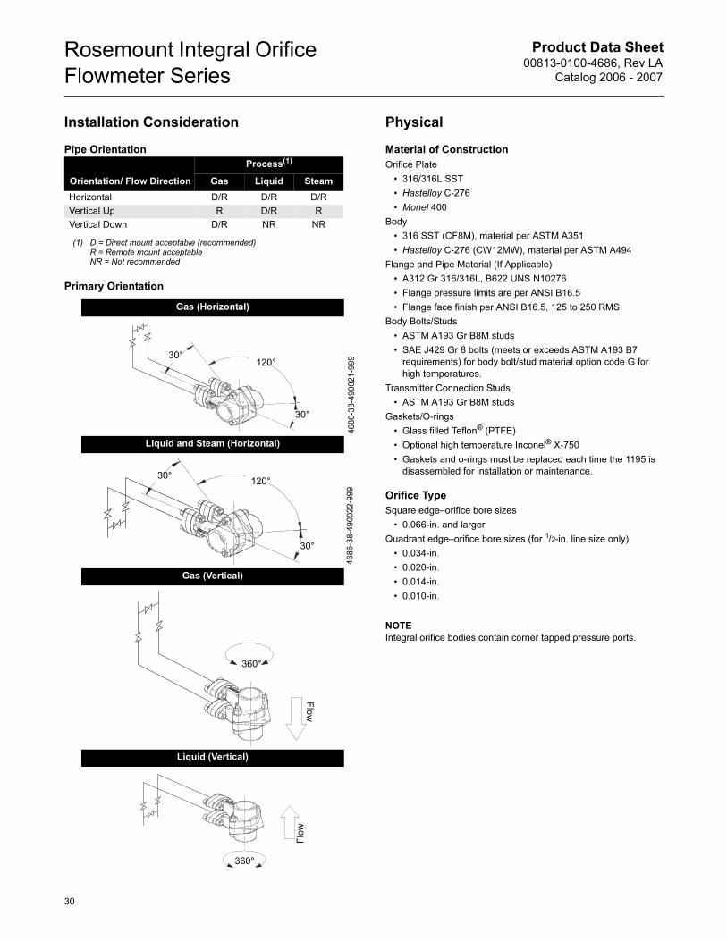
Product Data Sheet00813-0100-4686, Rev LA
Catalog 2006 - 2007
Rosemount Integral Orifice
Flowmeter Series
Installation Consideration
Pipe Orientation
Primary Orientation
Physical
Material of Construction
Orifice Plate
• 316/316L SST
• Hastelloy C-276
• Monel 400
Body
• 316 SST (CF8M), material per ASTM A351
• Hastelloy C-276 (CW12MW), material per ASTM A494
Flange and Pipe Material (If Applicable)
• A312 Gr 316/316L, B622 UNS N10276
• Flange pressure limits are per ANSI B16.5
• Flange face finish per ANSI B16.5, 125 to 250 RMS
Body Bolts/Studs
• ASTM A193 Gr B8M studs
• SAE J429 Gr 8 bolts (meets or exceeds ASTM A193 B7
requirements) for body bolt/stud material option code G for
high temperatures.
Transmitter Connection Studs
• ASTM A193 Gr B8M studs
Gaskets/O-rings
• Glass filled Teflon® (PTFE)
• Optional high temperature Inconel® X-750
• Gaskets and o-rings must be replaced each time the 1195 is
disassembled for installation or maintenance.
Orifice Type
Square edge–orifice bore sizes
• 0.066-in. and larger
Quadrant edge–orifice bore sizes (for 1/2-in. line size only)
• 0.034-in.
• 0.020-in.
• 0.014-in.
• 0.010-in.
NOTE
Integral orifice bodies contain corner tapped pressure ports.
Orientation/ Flow Direction
Process(1)
(1) D = Direct mount acceptable (recommended)R = Remote mount acceptableNR = Not recommended
Gas Liquid Steam
Horizontal D/R D/R D/R
Vertical Up R D/R R
Vertical Down D/R NR NR
Gas (Horizontal)
Liquid and Steam (Horizontal)
Gas (Vertical)
Liquid (Vertical)
30°
30°
120°
4686-38-490021-999
30°
30°
120°
4686-38-490022-999
360°
Flow
360°
Flow
30
Product Data Sheet00813-0100-4686, Rev LA
Catalog 2006 - 2007
Rosemount Integral Orifice
Flowmeter Series
Pipe Lengths
Upstream and downstream associated piping sections are
available on the 1195. The table below lists the standard overall
length (lay length) as a function of end connections and line size.
Transmitter Connections
21/8-in. (54 mm) center-to-center. Other transmitter spacing can be
accommodated using the optional remote adapters and
customer-supplied impulse piping. DIN 19213 connections are
available.
Torque Values of Standard Bolts
Orifice Body Studs (for body bolt/stud material codes C or D)
• 60 ft-lb (81 N-m)
Orifice Body Bolts (for body bolt/stud material code G)
• 78 ft-lb (105 N-m)
Transmitter studs
• 34-38 ft-lb (46-52 N-m)
3-valve manifold bolting
• 34-38 ft-lb (46-52 N-m)
Weight
The following weights are approximate
Line Size
Flanged Process Connection(1) (2) (3)
(1) See the ordering information for model code description.
(2) Consult factory for other lengths.
(3) See page 36 for additional information on associated pipe lengths.
1/2-in. (15 mm)
1-in. (25 mm)
11/2-in. (40 mm)
RF, ANSI Class 150, slip-on 18.2 (463) 28.9 (734) 40.3 (1023)
RF, ANSI Class 300, slip-on 18.2 (463) 28.9 (734) 40.3 (1023)
RF, ANSI Class 600, slip-on 18.2 (463) 28.9 (734) 40.3 (1023)
RF, DIN PN16, slip-on 18.2 (463) 28.9 (734) 40.3 (1023)
RF, DIN PN40, slip-on 18.2 (463) 28.9 (734) 40.3 (1023)
RF, DIN PN100, slip-on 18.2 (463) 28.9 (734) 40.3 (1023)
RF, ANSI Class 150, weld-neck 21.8 (554) 33.2 (843) 44.9 (1140)
RF, ANSI Class 300, weld-neck 22.2 (559) 33.7 (856) 45.5 (1156)
RF, ANSI Class 600, weld-neck 22.8 (579) 34.3 (871 46.1 (1171)
RTJ, ANSI Class 150, slip-on 18.2 (463) 28.9 (734) 40.3 (1023)
RTJ, ANSI Class 300, slip-on 18.2 (463) 28.9 (734) 40.3 (1023)
RTJ, ANSI Class 600, slip-on 18.2 (463) 28.9 (734) 40.3 (1023)
NPT / Beveled Process Connection(1)(2)(3)
18 (457) 28.9 (734) 40.3 (1023)
Line Size 1195 Only With Flanged Piping(1)
(1) As supplied with standard lengths, ANSI Class 150 flanges.
lb kg lb kg
1/2-in. (15 mm) 4.0 1.8 8 3.6
1-in. (25 mm) 6.0 2.7 12 5.4
11/2-in. (40 mm) 8.0 3.6 25 11.3
31
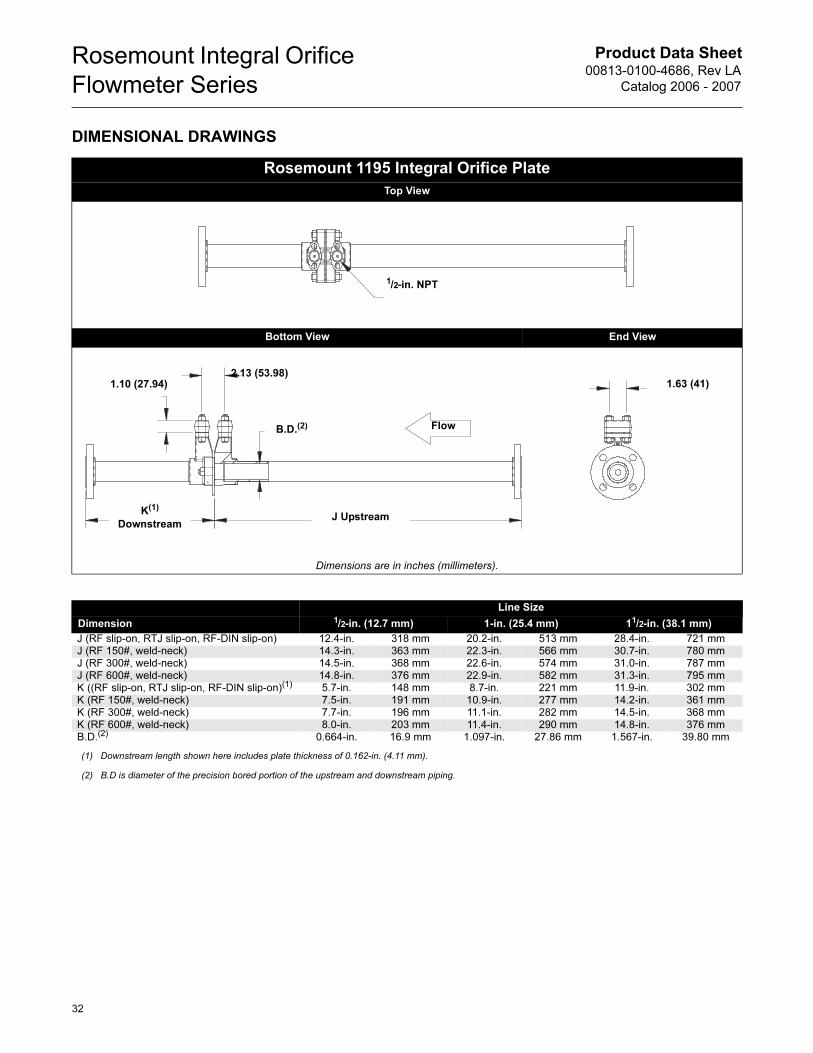
Product Data Sheet00813-0100-4686, Rev LA
Catalog 2006 - 2007
Rosemount Integral Orifice
Flowmeter Series
DIMENSIONAL DRAWINGS
Rosemount 1195 Integral Orifice Plate
Top View
Bottom View End View
Dimensions are in inches (millimeters).
1/2-in. NPT
1.63 (41)1.10 (27.94)2.13 (53.98)
Flow
J UpstreamK(1)
Downstream
B.D.(2)
Line Size
Dimension 1/2-in. (12.7 mm) 1-in. (25.4 mm) 11/2-in. (38.1 mm)
J (RF slip-on, RTJ slip-on, RF-DIN slip-on) 12.4-in. 318 mm 20.2-in. 513 mm 28.4-in. 721 mmJ (RF 150#, weld-neck) 14.3-in. 363 mm 22.3-in. 566 mm 30.7-in. 780 mmJ (RF 300#, weld-neck) 14.5-in. 368 mm 22.6-in. 574 mm 31.0-in. 787 mmJ (RF 600#, weld-neck) 14.8-in. 376 mm 22.9-in. 582 mm 31.3-in. 795 mmK ((RF slip-on, RTJ slip-on, RF-DIN slip-on)(1) 5.7-in. 148 mm 8.7-in. 221 mm 11.9-in. 302 mmK (RF 150#, weld-neck) 7.5-in. 191 mm 10.9-in. 277 mm 14.2-in. 361 mmK (RF 300#, weld-neck) 7.7-in. 196 mm 11.1-in. 282 mm 14.5-in. 368 mmK (RF 600#, weld-neck) 8.0-in. 203 mm 11.4-in. 290 mm 14.8-in. 376 mmB.D.(2) 0.664-in. 16.9 mm 1.097-in. 27.86 mm 1.567-in. 39.80 mm
(1) Downstream length shown here includes plate thickness of 0.162-in. (4.11 mm).
(2) B.D is diameter of the precision bored portion of the upstream and downstream piping.
32
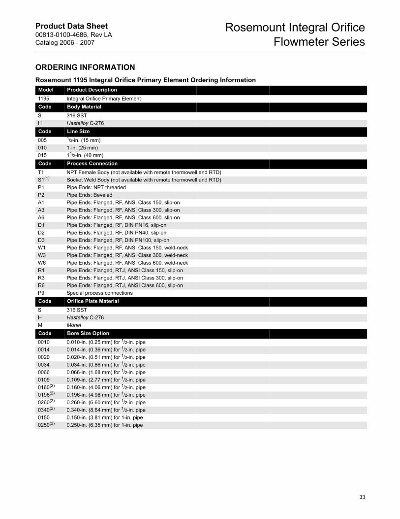
Product Data Sheet00813-0100-4686, Rev LA
Catalog 2006 - 2007
Rosemount Integral Orifice
Flowmeter Series
ORDERING INFORMATION
Rosemount 1195 Integral Orifice Primary Element Ordering Information
Model Product Description
1195 Integral Orifice Primary Element
Code Body Material
S 316 SST
H Hastelloy C-276
Code Line Size
005 1/2-in. (15 mm)
010 1-in. (25 mm)
015 11/2-in. (40 mm)
Code Process Connection
T1 NPT Female Body (not available with remote thermowell and RTD)
S1(1) Socket Weld Body (not available with remote thermowell and RTD)
P1 Pipe Ends: NPT threaded
P2 Pipe Ends: Beveled
A1 Pipe Ends: Flanged, RF, ANSI Class 150, slip-on
A3 Pipe Ends: Flanged, RF, ANSI Class 300, slip-on
A6 Pipe Ends: Flanged, RF, ANSI Class 600, slip-on
D1 Pipe Ends: Flanged, RF, DIN PN16, slip-on
D2 Pipe Ends: Flanged, RF, DIN PN40, slip-on
D3 Pipe Ends: Flanged, RF, DIN PN100, slip-on
W1 Pipe Ends: Flanged, RF, ANSI Class 150, weld-neck
W3 Pipe Ends: Flanged, RF, ANSI Class 300, weld-neck
W6 Pipe Ends: Flanged, RF, ANSI Class 600, weld-neck
R1 Pipe Ends: Flanged, RTJ, ANSI Class 150, slip-on
R3 Pipe Ends: Flanged, RTJ, ANSI Class 300, slip-on
R6 Pipe Ends: Flanged, RTJ, ANSI Class 600, slip-on
P9 Special process connections
Code Orifice Plate Material
S 316 SST
H Hastelloy C-276
M Monel
Code Bore Size Option
0010 0.010-in. (0.25 mm) for 1/2-in. pipe
0014 0.014-in. (0.36 mm) for 1/2-in. pipe
0020 0.020-in. (0.51 mm) for 1/2-in. pipe
0034 0.034-in. (0.86 mm) for 1/2-in. pipe
0066 0.066-in. (1.68 mm) for 1/2-in. pipe
0109 0.109-in. (2.77 mm) for 1/2-in. pipe
0160(2) 0.160-in. (4.06 mm) for 1/2-in. pipe
0196(2) 0.196-in. (4.98 mm) for 1/2-in. pipe
0260(2) 0.260-in. (6.60 mm) for 1/2-in. pipe
0340(2) 0.340-in. (8.64 mm) for 1/2-in. pipe
0150 0.150-in. (3.81 mm) for 1-in. pipe
0250(2) 0.250-in. (6.35 mm) for 1-in. pipe
33
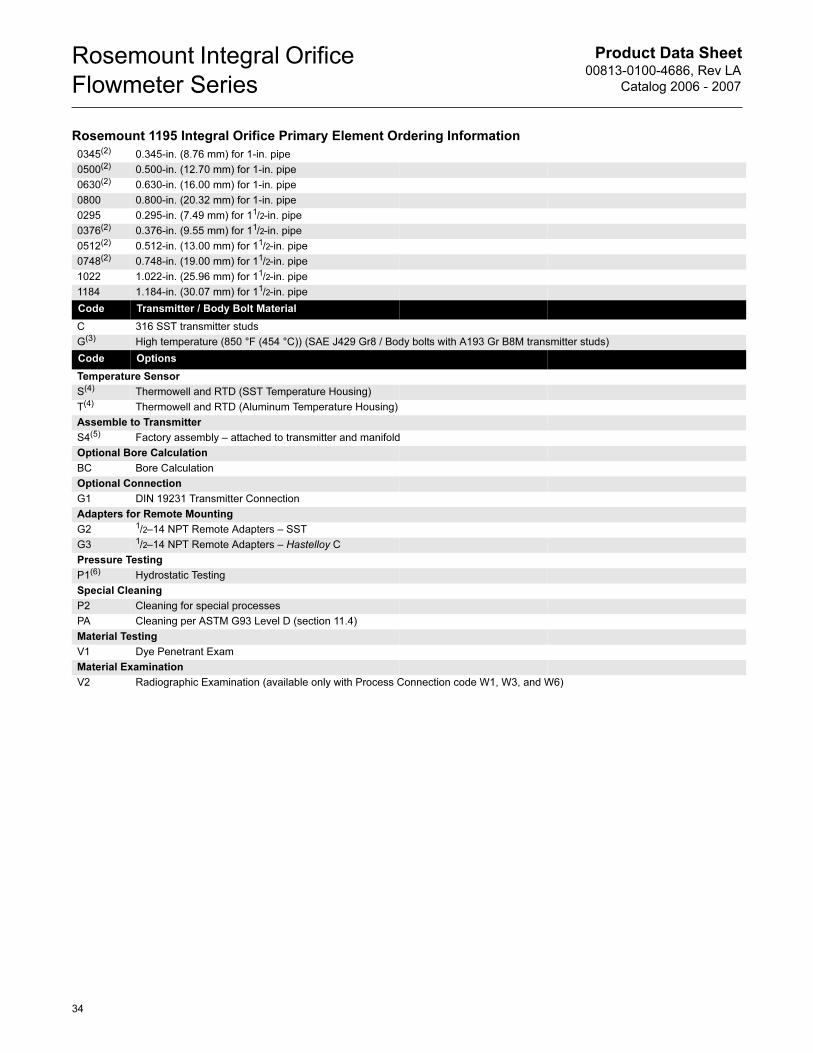
Product Data Sheet00813-0100-4686, Rev LA
Catalog 2006 - 2007
Rosemount Integral Orifice
Flowmeter Series
0345(2) 0.345-in. (8.76 mm) for 1-in. pipe
0500(2) 0.500-in. (12.70 mm) for 1-in. pipe
0630(2) 0.630-in. (16.00 mm) for 1-in. pipe
0800 0.800-in. (20.32 mm) for 1-in. pipe
0295 0.295-in. (7.49 mm) for 11/2-in. pipe
0376(2) 0.376-in. (9.55 mm) for 11/2-in. pipe
0512(2) 0.512-in. (13.00 mm) for 11/2-in. pipe
0748(2) 0.748-in. (19.00 mm) for 11/2-in. pipe
1022 1.022-in. (25.96 mm) for 11/2-in. pipe
1184 1.184-in. (30.07 mm) for 11/2-in. pipe
Code Transmitter / Body Bolt Material
C 316 SST transmitter studs
G(3) High temperature (850 °F (454 °C)) (SAE J429 Gr8 / Body bolts with A193 Gr B8M transmitter studs)
Code Options
Temperature Sensor
S(4) Thermowell and RTD (SST Temperature Housing)
T(4) Thermowell and RTD (Aluminum Temperature Housing)
Assemble to Transmitter
S4(5) Factory assembly – attached to transmitter and manifold
Optional Bore Calculation
BC Bore Calculation
Optional Connection
G1 DIN 19231 Transmitter Connection
Adapters for Remote Mounting
G2 1/2–14 NPT Remote Adapters – SST
G3 1/2–14 NPT Remote Adapters – Hastelloy C
Pressure Testing
P1(6) Hydrostatic Testing
Special Cleaning
P2 Cleaning for special processes
PA Cleaning per ASTM G93 Level D (section 11.4)
Material Testing
V1 Dye Penetrant Exam
Material Examination
V2 Radiographic Examination (available only with Process Connection code W1, W3, and W6)
Rosemount 1195 Integral Orifice Primary Element Ordering Information
34
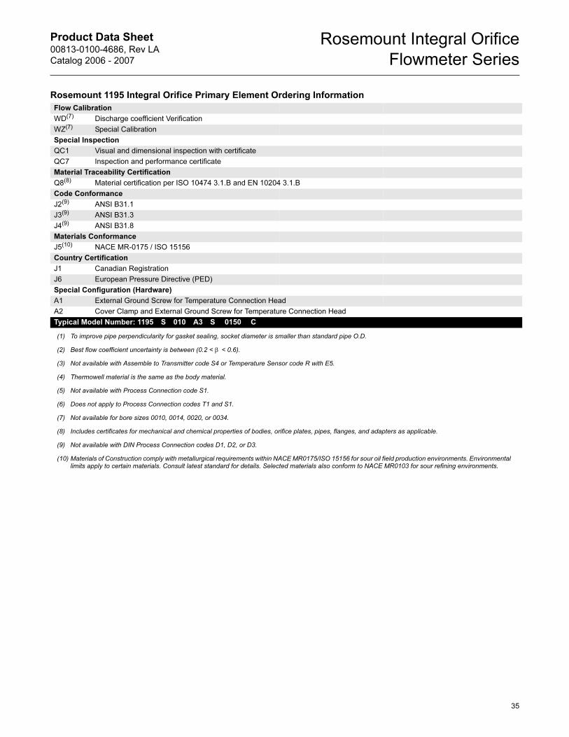
Product Data Sheet00813-0100-4686, Rev LA
Catalog 2006 - 2007
Rosemount Integral Orifice
Flowmeter Series
Flow Calibration
WD(7) Discharge coefficient Verification
WZ(7) Special Calibration
Special Inspection
QC1 Visual and dimensional inspection with certificate
QC7 Inspection and performance certificate
Material Traceability Certification
Q8(8) Material certification per ISO 10474 3.1.B and EN 10204 3.1.B
Code Conformance
J2(9) ANSI B31.1
J3(9) ANSI B31.3
J4(9) ANSI B31.8
Materials Conformance
J5(10) NACE MR-0175 / ISO 15156
Country Certification
J1 Canadian Registration
J6 European Pressure Directive (PED)
Special Configuration (Hardware)
A1 External Ground Screw for Temperature Connection Head
A2 Cover Clamp and External Ground Screw for Temperature Connection Head
Typical Model Number: 1195 S 010 A3 S 0150 C
(1) To improve pipe perpendicularity for gasket sealing, socket diameter is smaller than standard pipe O.D.
(2) Best flow coefficient uncertainty is between (0.2 < β < 0.6).
(3) Not available with Assemble to Transmitter code S4 or Temperature Sensor code R with E5.
(4) Thermowell material is the same as the body material.
(5) Not available with Process Connection code S1.
(6) Does not apply to Process Connection codes T1 and S1.
(7) Not available for bore sizes 0010, 0014, 0020, or 0034.
(8) Includes certificates for mechanical and chemical properties of bodies, orifice plates, pipes, flanges, and adapters as applicable.
(9) Not available with DIN Process Connection codes D1, D2, or D3.
(10) Materials of Construction comply with metallurgical requirements within NACE MR0175/ISO 15156 for sour oil field production environments. Environmental limits apply to certain materials. Consult latest standard for details. Selected materials also conform to NACE MR0103 for sour refining environments.
Rosemount 1195 Integral Orifice Primary Element Ordering Information
35
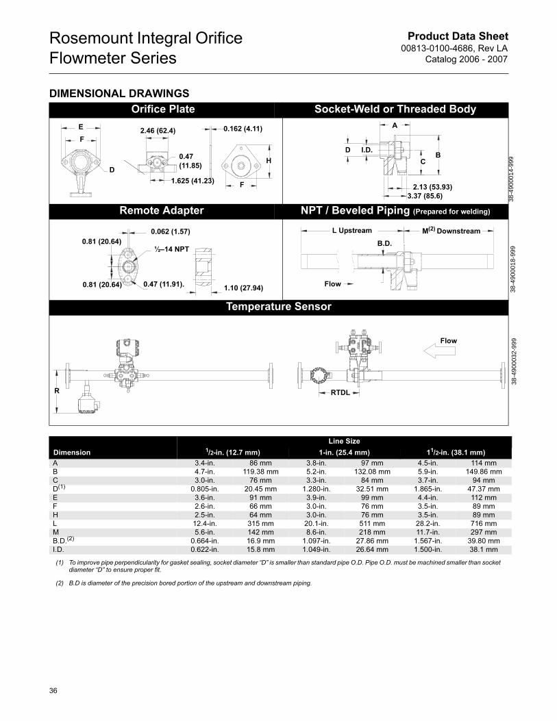
Product Data Sheet00813-0100-4686, Rev LA
Catalog 2006 - 2007
Rosemount Integral Orifice
Flowmeter Series
DIMENSIONAL DRAWINGS
Orifice Plate Socket-Weld or Threaded Body
Remote Adapter NPT / Beveled Piping (Prepared for welding)
Temperature Sensor
D
E
F
1.625 (41.23)F
H0.47
(11.85)
2.46 (62.4) 0.162 (4.11)
2.13 (53.93)
3.37 (85.6)
A
CB
D I.D.
38-4
9000
14-9
99
0.062 (1.57)
½–14 NPT
0.47 (11.91).0.81 (20.64)
0.81 (20.64)
1.10 (27.94)
B.D.
L Upstream M(2) Downstream
Flow
38-4
9000
18-9
9938
-490
0032
-999
RTDLR
Flow
Line Size
Dimension 1/2-in. (12.7 mm) 1-in. (25.4 mm) 11/2-in. (38.1 mm)
A 3.4-in. 86 mm 3.8-in. 97 mm 4.5-in. 114 mm
B 4.7-in. 119.38 mm 5.2-in. 132.08 mm 5.9-in. 149.86 mm
C 3.0-in. 76 mm 3.3-in. 84 mm 3.7-in. 94 mm
D(1) 0.805-in. 20.45 mm 1.280-in. 32.51 mm 1.865-in. 47.37 mm
E 3.6-in. 91 mm 3.9-in. 99 mm 4.4-in. 112 mm
F 2.6-in. 66 mm 3.0-in. 76 mm 3.5-in. 89 mm
H 2.5-in. 64 mm 3.0-in. 76 mm 3.5-in. 89 mm
L 12.4-in. 315 mm 20.1-in. 511 mm 28.2-in. 716 mm
M 5.6-in. 142 mm 8.6-in. 218 mm 11.7-in. 297 mm
B.D.(2) 0.664-in. 16.9 mm 1.097-in. 27.86 mm 1.567-in. 39.80 mm
I.D. 0.622-in. 15.8 mm 1.049-in. 26.64 mm 1.500-in. 38.1 mm
(1) To improve pipe perpendicularity for gasket sealing, socket diameter “D” is smaller than standard pipe O.D. Pipe O.D. must be machined smaller than socket diameter “D” to ensure proper fit.
(2) B.D is diameter of the precision bored portion of the upstream and downstream piping.
36
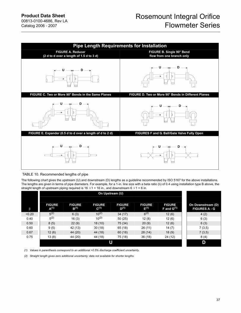
Product Data Sheet00813-0100-4686, Rev LA
Catalog 2006 - 2007
Rosemount Integral Orifice
Flowmeter Series
TABLE 10. Recommended lengths of pipe
Pipe Length Requirements for Installation
FIGURE A. Reducer
(2 d to d over a length of 1.5 d to 3 d)
FIGURE B. Single 90° Bend
flow from one branch only
FIGURE C. Two or More 90° Bends in the Same Planes FIGURE D. Two or More 90° Bends in Different Planes
FIGURE E. Expander (0.5 d to d over a length of d to 2 d) FIGURES F and G. Ball/Gate Valve Fully Open
The following chart gives the upstream (U) and downstream (D) lengths as a guideline recommended by ISO 5167 for the above installations.
The lengths are given in terms of pipe diameters. For example, for a 1-in. line size with a beta ratio (b) of 0.4 using installation type B above, the
straight length of upstream piping required is 16 �1 = 16 in., and downstream 6 �1 = 6 in.
β
On Upstream (U)
On Downstream (D)
FIGURES A - G
FIGURE
A(1)
(1) Values in parenthesis correspond to an additional +0.5% discharge coefficient uncertainty.
FIGURE
B(1)FIGURE
C(1)FIGURE
D(1)FIGURE
E(1)FIGURE
F and G(1)
<0.20 5(2)
(2) Straight length gives zero additional uncertainty; data not available for shorter lengths.
6 (3) 10(2) 34 (17) 6(2) 12 (6) 4 (2)
0.40 5(2) 16 (3) 10(2) 50 (25) 12 (8) 12 (6) 6 (3)
0.50 8 (5) 22 (9) 18 (10) 75 (34) 20 (9) 12 (6) 6 (3)
0.60 9 (5) 42 (13) 30 (18) 65 (18) 26 (11) 14 (7) 7 (3,5)
0.67 12 (6) 44 (20) 44 (18) 60 (18) 28 (14) 18 (9) 7 (3,5)
0.75 13 (8) 44 (20) 44 (18) 75 (18) 36 (18) 24 (12) 8 (4)
U D
U DU D
U DU D
U D U D
37
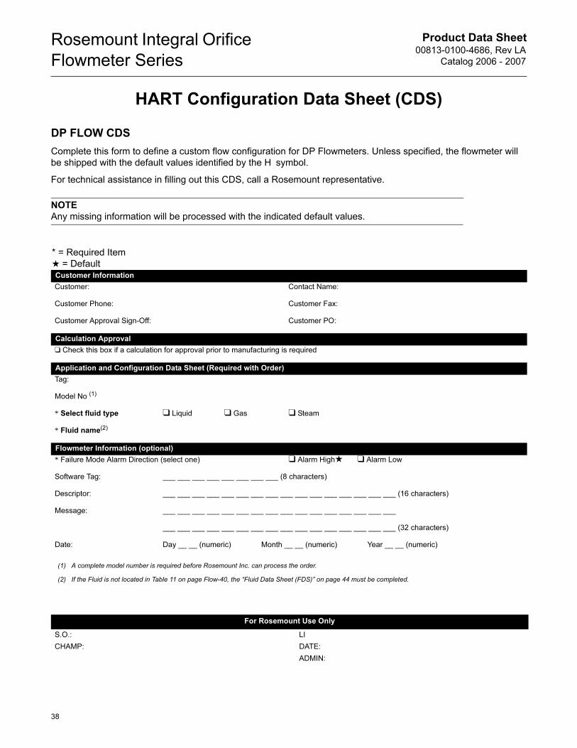
Product Data Sheet00813-0100-4686, Rev LA
Catalog 2006 - 2007
Rosemount Integral Orifice
Flowmeter Series
HART Configuration Data Sheet (CDS)
DP FLOW CDS
Complete this form to define a custom flow configuration for DP Flowmeters. Unless specified, the flowmeter will
be shipped with the default values identified by the H symbol.
For technical assistance in filling out this CDS, call a Rosemount representative.
NOTE
Any missing information will be processed with the indicated default values.
* = Required Item
★ = DefaultCustomer Information
Customer: Contact Name:
Customer Phone: Customer Fax:
Customer Approval Sign-Off: Customer PO:
Calculation Approval
❑ Check this box if a calculation for approval prior to manufacturing is required
Application and Configuration Data Sheet (Required with Order)
Tag:
Model No (1)
* Select fluid type ❑ Liquid ❑ Gas ❑ Steam
* Fluid name(2)
Flowmeter Information (optional)
* Failure Mode Alarm Direction (select one) ❑ Alarm High★ ❑ Alarm Low
Software Tag: ___ ___ ___ ___ ___ ___ ___ ___ (8 characters)
Descriptor: ___ ___ ___ ___ ___ ___ ___ ___ ___ ___ ___ ___ ___ ___ ___ ___ (16 characters)
Message: ___ ___ ___ ___ ___ ___ ___ ___ ___ ___ ___ ___ ___ ___ ___ ___
___ ___ ___ ___ ___ ___ ___ ___ ___ ___ ___ ___ ___ ___ ___ ___ (32 characters)
Date: Day __ __ (numeric) Month __ __ (numeric) Year __ __ (numeric)
(1) A complete model number is required before Rosemount Inc. can process the order.
(2) If the Fluid is not located in Table 11 on page Flow-40, the “Fluid Data Sheet (FDS)” on page 44 must be completed.
For Rosemount Use Only
S.O.: LI
CHAMP: DATE:
ADMIN:
38
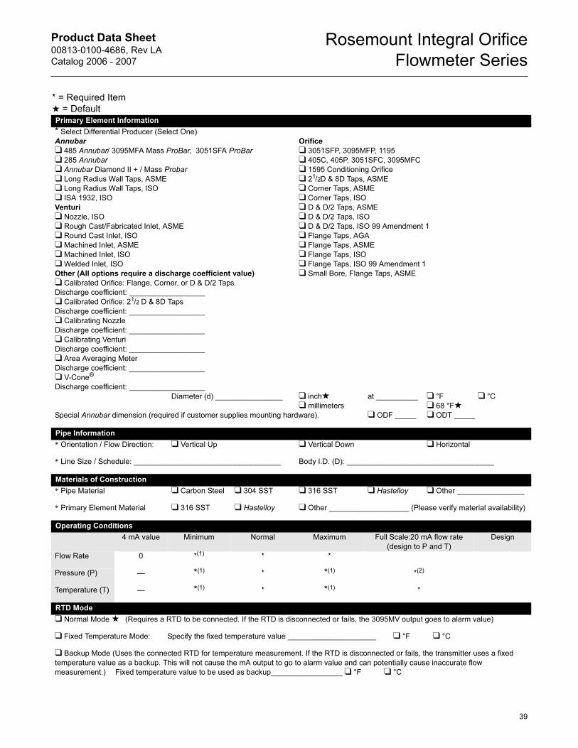
Product Data Sheet00813-0100-4686, Rev LA
Catalog 2006 - 2007
Rosemount Integral Orifice
Flowmeter Series
* = Required Item
★ = DefaultPrimary Element Information
* Select Differential Producer (Select One)
Annubar
❑ 485 Annubar/ 3095MFA Mass ProBar, 3051SFA ProBar
❑ 285 Annubar
❑ Annubar Diamond II + / Mass Probar
❑ Long Radius Wall Taps, ASME
❑ Long Radius Wall Taps, ISO
❑ ISA 1932, ISO
Venturi
❑ Nozzle, ISO
❑ Rough Cast/Fabricated Inlet, ASME
❑ Round Cast Inlet, ISO
❑ Machined Inlet, ASME
❑ Machined Inlet, ISO
❑ Welded Inlet, ISO
Other (All options require a discharge coefficient value)
❑ Calibrated Orifice: Flange, Corner, or D & D/2 Taps.
Discharge coefficient: __________________
❑ Calibrated Orifice: 21/2 D & 8D Taps
Discharge coefficient: __________________
❑ Calibrating Nozzle
Discharge coefficient: __________________
❑ Calibrating Venturi
Discharge coefficient: __________________
❑ Area Averaging Meter
Discharge coefficient: __________________
❑ V-Cone®
Discharge coefficient: __________________
Orifice
❑ 3051SFP, 3095MFP, 1195
❑ 405C, 405P, 3051SFC, 3095MFC
❑ 1595 Conditioning Orifice
❑ 21/2D & 8D Taps, ASME
❑ Corner Taps, ASME
❑ Corner Taps, ISO
❑ D & D/2 Taps, ASME
❑ D & D/2 Taps, ISO
❑ D & D/2 Taps, ISO 99 Amendment 1
❑ Flange Taps, AGA
❑ Flange Taps, ASME
❑ Flange Taps, ISO
❑ Flange Taps, ISO 99 Amendment 1
❑ Small Bore, Flange Taps, ASME
Diameter (d) ________________ ❑ inch★❑ millimeters
at __________ ❑ °F
❑ 68 °F★❑ °C
Special Annubar dimension (required if customer supplies mounting hardware). ❑ ODF _____ ❑ ODT _____
Pipe Information
* Orientation / Flow Direction: ❑ Vertical Up ❑ Vertical Down ❑ Horizontal
* Line Size / Schedule: ___________________________________ Body I.D. (D): ___________________________________
Materials of Construction
* Pipe Material ❑ Carbon Steel ❑ 304 SST ❑ 316 SST ❑ Hastelloy ❑ Other ________________
* Primary Element Material ❑ 316 SST ❑ Hastelloy ❑ Other ___________________ (Please verify material availability)
Operating Conditions
4 mA value Minimum Normal Maximum Full Scale:20 mA flow rate
(design to P and T)
Design
Flow Rate 0 *(1) * *
Pressure (P) — *(1) * *(1) *(2)
Temperature (T) — *(1) * *(1) *
RTD Mode
❑ Normal Mode ★ (Requires a RTD to be connected. If the RTD is disconnected or fails, the 3095MV output goes to alarm value)
❑ Fixed Temperature Mode: Specify the fixed temperature value _____________________ ❑ °F ❑ °C
❑ Backup Mode (Uses the connected RTD for temperature measurement. If the RTD is disconnected or fails, the transmitter uses a fixed
temperature value as a backup. This will not cause the mA output to go to alarm value and can potentially cause inaccurate flow
measurement.) Fixed temperature value to be used as backup_________________ ❑ °F ❑ °C
39
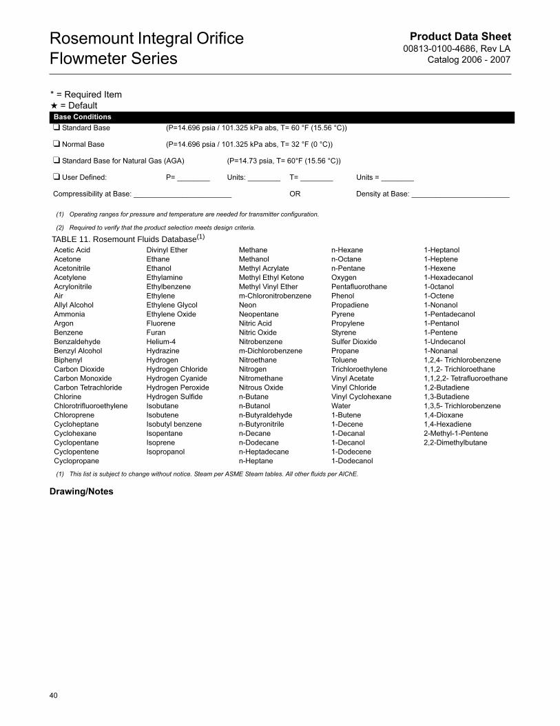
Product Data Sheet00813-0100-4686, Rev LA
Catalog 2006 - 2007
Rosemount Integral Orifice
Flowmeter Series
Drawing/Notes
Base Conditions
❑ Standard Base (P=14.696 psia / 101.325 kPa abs, T= 60 °F (15.56 °C))
❑ Normal Base (P=14.696 psia / 101.325 kPa abs, T= 32 °F (0 °C))
❑ Standard Base for Natural Gas (AGA) (P=14.73 psia, T= 60°F (15.56 °C))
❑ User Defined: P= ________ Units: ________ T= ________ Units = ________
Compressibility at Base: ________________________ OR Density at Base: ________________________
(1) Operating ranges for pressure and temperature are needed for transmitter configuration.
(2) Required to verify that the product selection meets design criteria.
* = Required Item
★ = Default
TABLE 11. Rosemount Fluids Database(1)
Acetic Acid
Acetone
Acetonitrile
Acetylene
Acrylonitrile
Air
Allyl Alcohol
Ammonia
Argon
Benzene
Benzaldehyde
Benzyl Alcohol
Biphenyl
Carbon Dioxide
Carbon Monoxide
Carbon Tetrachloride
Chlorine
Chlorotrifluoroethylene
Chloroprene
Cycloheptane
Cyclohexane
Cyclopentane
Cyclopentene
Cyclopropane
Divinyl Ether
Ethane
Ethanol
Ethylamine
Ethylbenzene
Ethylene
Ethylene Glycol
Ethylene Oxide
Fluorene
Furan
Helium-4
Hydrazine
Hydrogen
Hydrogen Chloride
Hydrogen Cyanide
Hydrogen Peroxide
Hydrogen Sulfide
Isobutane
Isobutene
Isobutyl benzene
Isopentane
Isoprene
Isopropanol
Methane
Methanol
Methyl Acrylate
Methyl Ethyl Ketone
Methyl Vinyl Ether
m-Chloronitrobenzene
Neon
Neopentane
Nitric Acid
Nitric Oxide
Nitrobenzene
m-Dichlorobenzene
Nitroethane
Nitrogen
Nitromethane
Nitrous Oxide
n-Butane
n-Butanol
n-Butyraldehyde
n-Butyronitrile
n-Decane
n-Dodecane
n-Heptadecane
n-Heptane
n-Hexane
n-Octane
n-Pentane
Oxygen
Pentafluorothane
Phenol
Propadiene
Pyrene
Propylene
Styrene
Sulfer Dioxide
Propane
Toluene
Trichloroethylene
Vinyl Acetate
Vinyl Chloride
Vinyl Cyclohexane
Water
1-Butene
1-Decene
1-Decanal
1-Decanol
1-Dodecene
1-Dodecanol
1-Heptanol
1-Heptene
1-Hexene
1-Hexadecanol
1-0ctanol
1-Octene
1-Nonanol
1-Pentadecanol
1-Pentanol
1-Pentene
1-Undecanol
1-Nonanal
1,2,4- Trichlorobenzene
1,1,2- Trichloroethane
1,1,2,2- Tetrafluoroethane
1,2-Butadiene
1,3-Butadiene
1,3,5- Trichlorobenzene
1,4-Dioxane
1,4-Hexadiene
2-Methyl-1-Pentene
2,2-Dimethylbutane
(1) This list is subject to change without notice. Steam per ASME Steam tables. All other fluids per AlChE.
40
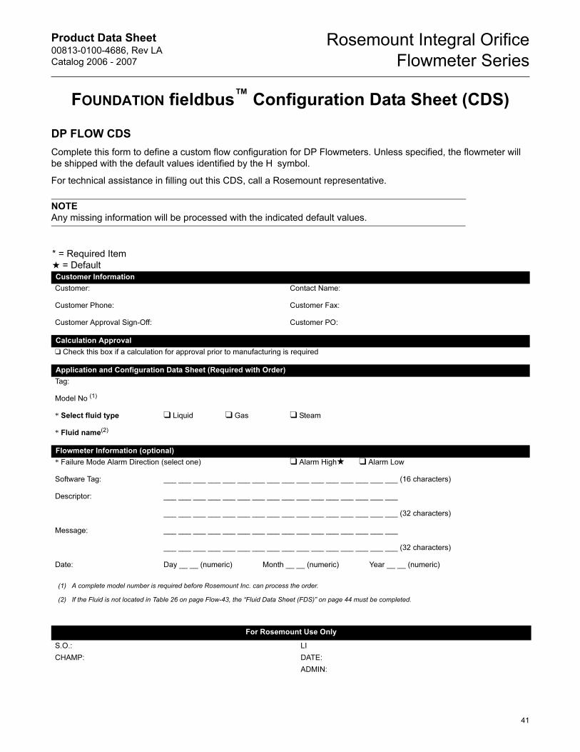
Product Data Sheet00813-0100-4686, Rev LA
Catalog 2006 - 2007
Rosemount Integral Orifice
Flowmeter Series
FOUNDATION fieldbus™ Configuration Data Sheet (CDS)
DP FLOW CDS
Complete this form to define a custom flow configuration for DP Flowmeters. Unless specified, the flowmeter will
be shipped with the default values identified by the H symbol.
For technical assistance in filling out this CDS, call a Rosemount representative.
NOTE
Any missing information will be processed with the indicated default values.
* = Required Item
★ = DefaultCustomer Information
Customer: Contact Name:
Customer Phone: Customer Fax:
Customer Approval Sign-Off: Customer PO:
Calculation Approval
❑ Check this box if a calculation for approval prior to manufacturing is required
Application and Configuration Data Sheet (Required with Order)
Tag:
Model No (1)
* Select fluid type ❑ Liquid ❑ Gas ❑ Steam
* Fluid name(2)
Flowmeter Information (optional)
* Failure Mode Alarm Direction (select one) ❑ Alarm High★ ❑ Alarm Low
Software Tag: ___ ___ ___ ___ ___ ___ ___ ___ ___ ___ ___ ___ ___ ___ ___ ___ (16 characters)
Descriptor: ___ ___ ___ ___ ___ ___ ___ ___ ___ ___ ___ ___ ___ ___ ___ ___
___ ___ ___ ___ ___ ___ ___ ___ ___ ___ ___ ___ ___ ___ ___ ___ (32 characters)
Message: ___ ___ ___ ___ ___ ___ ___ ___ ___ ___ ___ ___ ___ ___ ___ ___
___ ___ ___ ___ ___ ___ ___ ___ ___ ___ ___ ___ ___ ___ ___ ___ (32 characters)
Date: Day __ __ (numeric) Month __ __ (numeric) Year __ __ (numeric)
(1) A complete model number is required before Rosemount Inc. can process the order.
(2) If the Fluid is not located in Table 26 on page Flow-43, the “Fluid Data Sheet (FDS)” on page 44 must be completed.
For Rosemount Use Only
S.O.: LI
CHAMP: DATE:
ADMIN:
41
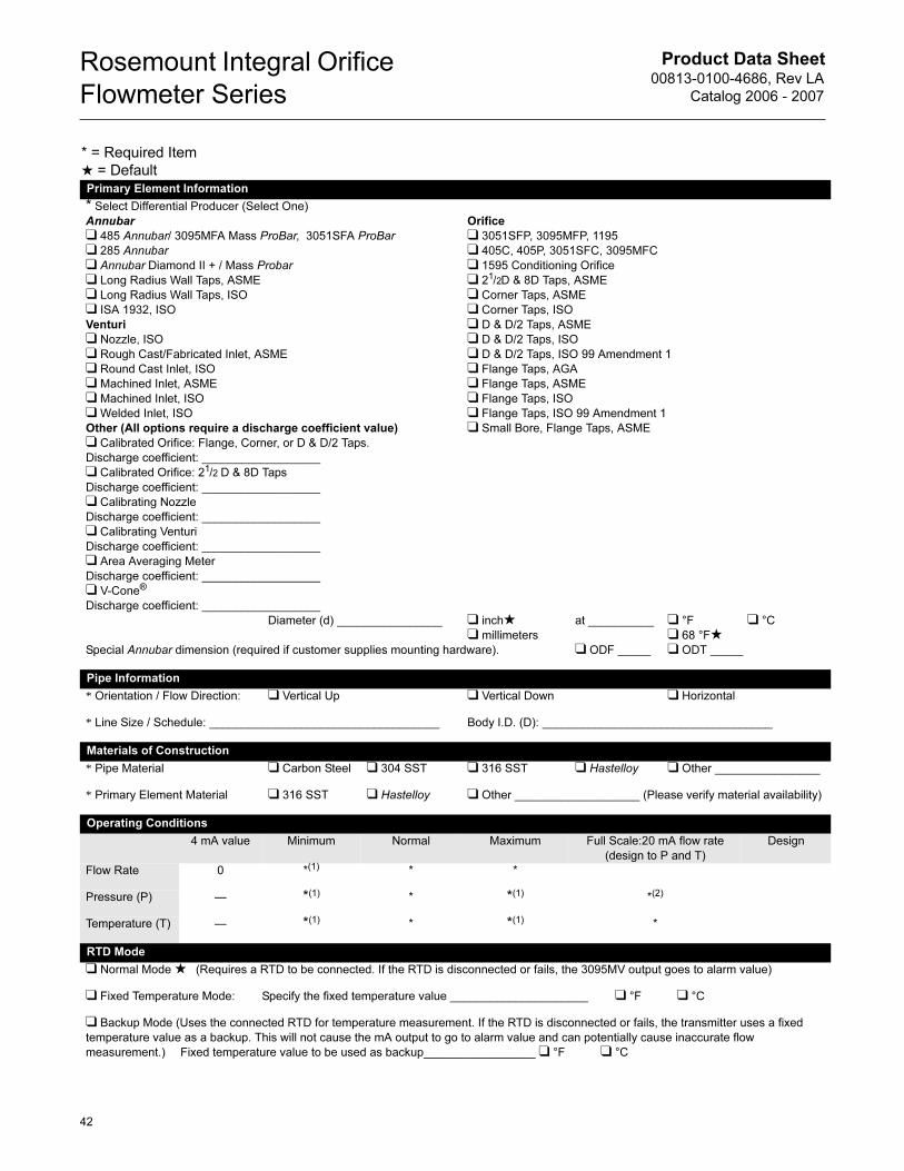
Product Data Sheet00813-0100-4686, Rev LA
Catalog 2006 - 2007
Rosemount Integral Orifice
Flowmeter Series
* = Required Item
★ = DefaultPrimary Element Information
* Select Differential Producer (Select One)
Annubar
❑ 485 Annubar/ 3095MFA Mass ProBar, 3051SFA ProBar
❑ 285 Annubar
❑ Annubar Diamond II + / Mass Probar
❑ Long Radius Wall Taps, ASME
❑ Long Radius Wall Taps, ISO
❑ ISA 1932, ISO
Venturi
❑ Nozzle, ISO
❑ Rough Cast/Fabricated Inlet, ASME
❑ Round Cast Inlet, ISO
❑ Machined Inlet, ASME
❑ Machined Inlet, ISO
❑ Welded Inlet, ISO
Other (All options require a discharge coefficient value)
❑ Calibrated Orifice: Flange, Corner, or D & D/2 Taps.
Discharge coefficient: __________________
❑ Calibrated Orifice: 21/2 D & 8D Taps
Discharge coefficient: __________________
❑ Calibrating Nozzle
Discharge coefficient: __________________
❑ Calibrating Venturi
Discharge coefficient: __________________
❑ Area Averaging Meter
Discharge coefficient: __________________
❑ V-Cone®
Discharge coefficient: __________________
Orifice
❑ 3051SFP, 3095MFP, 1195
❑ 405C, 405P, 3051SFC, 3095MFC
❑ 1595 Conditioning Orifice
❑ 21/2D & 8D Taps, ASME
❑ Corner Taps, ASME
❑ Corner Taps, ISO
❑ D & D/2 Taps, ASME
❑ D & D/2 Taps, ISO
❑ D & D/2 Taps, ISO 99 Amendment 1
❑ Flange Taps, AGA
❑ Flange Taps, ASME
❑ Flange Taps, ISO
❑ Flange Taps, ISO 99 Amendment 1
❑ Small Bore, Flange Taps, ASME
Diameter (d) ________________ ❑ inch★❑ millimeters
at __________ ❑ °F
❑ 68 °F★❑ °C
Special Annubar dimension (required if customer supplies mounting hardware). ❑ ODF _____ ❑ ODT _____
Pipe Information
* Orientation / Flow Direction: ❑ Vertical Up ❑ Vertical Down ❑ Horizontal
* Line Size / Schedule: ___________________________________ Body I.D. (D): ___________________________________
Materials of Construction
* Pipe Material ❑ Carbon Steel ❑ 304 SST ❑ 316 SST ❑ Hastelloy ❑ Other ________________
* Primary Element Material ❑ 316 SST ❑ Hastelloy ❑ Other ___________________ (Please verify material availability)
Operating Conditions
4 mA value Minimum Normal Maximum Full Scale:20 mA flow rate
(design to P and T)
Design
Flow Rate 0 *(1) * *
Pressure (P) — *(1) * *(1) *(2)
Temperature (T) — *(1) * *(1) *
RTD Mode
❑ Normal Mode ★ (Requires a RTD to be connected. If the RTD is disconnected or fails, the 3095MV output goes to alarm value)
❑ Fixed Temperature Mode: Specify the fixed temperature value _____________________ ❑ °F ❑ °C
❑ Backup Mode (Uses the connected RTD for temperature measurement. If the RTD is disconnected or fails, the transmitter uses a fixed
temperature value as a backup. This will not cause the mA output to go to alarm value and can potentially cause inaccurate flow
measurement.) Fixed temperature value to be used as backup_________________ ❑ °F ❑ °C
42
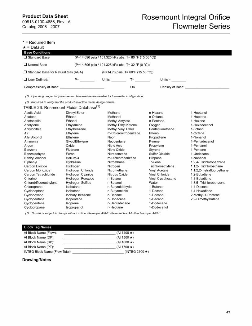
Product Data Sheet00813-0100-4686, Rev LA
Catalog 2006 - 2007
Rosemount Integral Orifice
Flowmeter Series
Drawing/Notes
Base Conditions
❑ Standard Base (P=14.696 psia / 101.325 kPa abs, T= 60 °F (15.56 °C))
❑ Normal Base (P=14.696 psia / 101.325 kPa abs, T= 32 °F (0 °C))
❑ Standard Base for Natural Gas (AGA) (P=14.73 psia, T= 60°F (15.56 °C))
❑ User Defined: P= ________ Units: ________ T= ________ Units = ________
Compressibility at Base: ________________________ OR Density at Base: ________________________
(1) Operating ranges for pressure and temperature are needed for transmitter configuration.
(2) Required to verify that the product selection meets design criteria.
* = Required Item
★ = Default
TABLE 26. Rosemount Fluids Database(1)
Acetic Acid
Acetone
Acetonitrile
Acetylene
Acrylonitrile
Air
Allyl Alcohol
Ammonia
Argon
Benzene
Benzaldehyde
Benzyl Alcohol
Biphenyl
Carbon Dioxide
Carbon Monoxide
Carbon Tetrachloride
Chlorine
Chlorotrifluoroethylene
Chloroprene
Cycloheptane
Cyclohexane
Cyclopentane
Cyclopentene
Cyclopropane
Divinyl Ether
Ethane
Ethanol
Ethylamine
Ethylbenzene
Ethylene
Ethylene
GlycolEthylene
Oxide
Fluorene
Furan
Helium-4
Hydrazine
Hydrogen
Hydrogen Chloride
Hydrogen Cyanide
Hydrogen Peroxide
Hydrogen Sulfide
Isobutane
Isobutene
Isobutyl benzene
Isopentane
Isoprene
Isopropanol
Methane
Methanol
Methyl Acrylate
Methyl Ethyl Ketone
Methyl Vinyl Ether
m-Chloronitrobenzene
Neon
Neopentane
Nitric Acid
Nitric Oxide
Nitrobenzene
m-Dichlorobenzene
Nitroethane
Nitrogen
Nitromethane
Nitrous Oxide
n-Butane
n-Butanol
n-Butyraldehyde
n-Butyronitrile
n-Decane
n-Dodecane
n-Heptadecane
n-Heptane
n-Hexane
n-Octane
n-Pentane
Oxygen
Pentafluorothane
Phenol
Propadiene
Pyrene
Propylene
Styrene
Sulfer Dioxide
Propane
Toluene
Trichloroethylene
Vinyl Acetate
Vinyl Chloride
Vinyl Cyclohexane
Water
1-Butene
1-Decene
1-Decanal
1-Decanol
1-Dodecene
1-Dodecanol
1-Heptanol
1-Heptene
1-Hexene
1-Hexadecanol
1-0ctanol
1-Octene
1-Nonanol
1-Pentadecanol
1-Pentanol
1-Pentene
1-Undecanol
1-Nonanal
1,2,4- Trichlorobenzene
1,1,2- Trichloroethane
1,1,2,2- Tetrafluoroethane
1,2-Butadiene
1,3-Butadiene
1,3,5- Trichlorobenzene
1,4-Dioxane
1,4-Hexadiene
2-Methyl-1-Pentene
2,2-Dimethylbutane
(1) This list is subject to change without notice. Steam per ASME Steam tables. All other fluids per AlChE.
Block Tag Names
AI Block Name (Flow): ____________________________ (AI 1400 ★)
AI Block Name (DP): ____________________________ (AI 1500 ★)
AI Block Name (SP): ____________________________ (AI 1600 ★)
AI Block Name (PT): ____________________________ (AI 1700 ★)
INTEG Block Name (Flow Total): ____________________________ (INTEG 2100 ★)
43
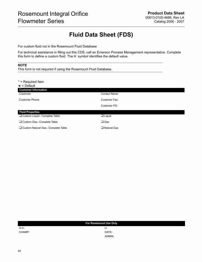
Product Data Sheet00813-0100-4686, Rev LA
Catalog 2006 - 2007
Rosemount Integral Orifice
Flowmeter Series
Fluid Data Sheet (FDS)
For custom fluid not in the Rosemount Fluid Database
For technical assistance in filling out this CDS, call an Emerson Process Management representative. Complete
this form to define a custom fluid. The H symbol identifies the default value.
NOTE
This form is not required if using the Rosemount Fluid Database.
* = Required Item
★ = DefaultCustomer Information
Customer: Contact Name:
Customer Phone: Customer Fax:
Customer PO:
Fluid Properties
❑ Custom Liquid– Complete Table ❑ Liquid
❑ Custom Gas– Complete Table ❑ Gas
❑ Custom Natural Gas– Complete Table ❑ Natural Gas
For Rosemount Use Only
S.O.: LI
CHAMP: DATE:
ADMIN:
44
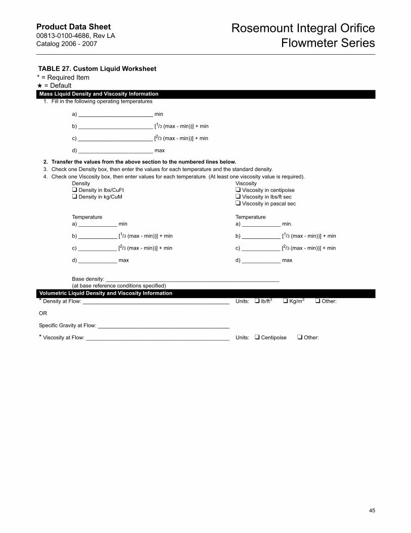
Product Data Sheet00813-0100-4686, Rev LA
Catalog 2006 - 2007
Rosemount Integral Orifice
Flowmeter Series
TABLE 27. Custom Liquid Worksheet
* = Required Item
★ = DefaultMass Liquid Density and Viscosity Information
1. Fill in the following operating temperatures
a) _________________________ min
b) _________________________ [1/3 (max - min))] + min
c) _________________________ [2/3 (max - min))] + min
d) _________________________ max
2. Transfer the values from the above section to the numbered lines below.
3. Check one Density box, then enter the values for each temperature and the standard density.
4. Check one Viscosity box, then enter values for each temperature. (At least one viscosity value is required).
Density
❑ Density in lbs/CuFt
❑ Density in kg/CuM
Viscosity
❑ Viscosity in centipoise
❑ Viscosity in lbs/ft sec
❑ Viscosity in pascal sec
Temperature Temperature
a) _____________ min a) _____________ min.
b) _____________ [1/3 (max - min))] + min b) _____________ [1/3 (max - min))] + min
c) _____________ [2/3 (max - min))] + min c) _____________ [2/3 (max - min))] + min
d) _____________ max d) _____________ max
Base density: __________________________________________________________
(at base reference conditions specified)
Volumetric Liquid Density and Viscosity Information
* Density at Flow: _________________________________________________ Units: ❑ lb/ft3 ❑ Kg/m3 ❑ Other:
OR
Specific Gravity at Flow: ____________________________________________
* Viscosity at Flow: ________________________________________________ Units: ❑ Centipoise ❑ Other:
45
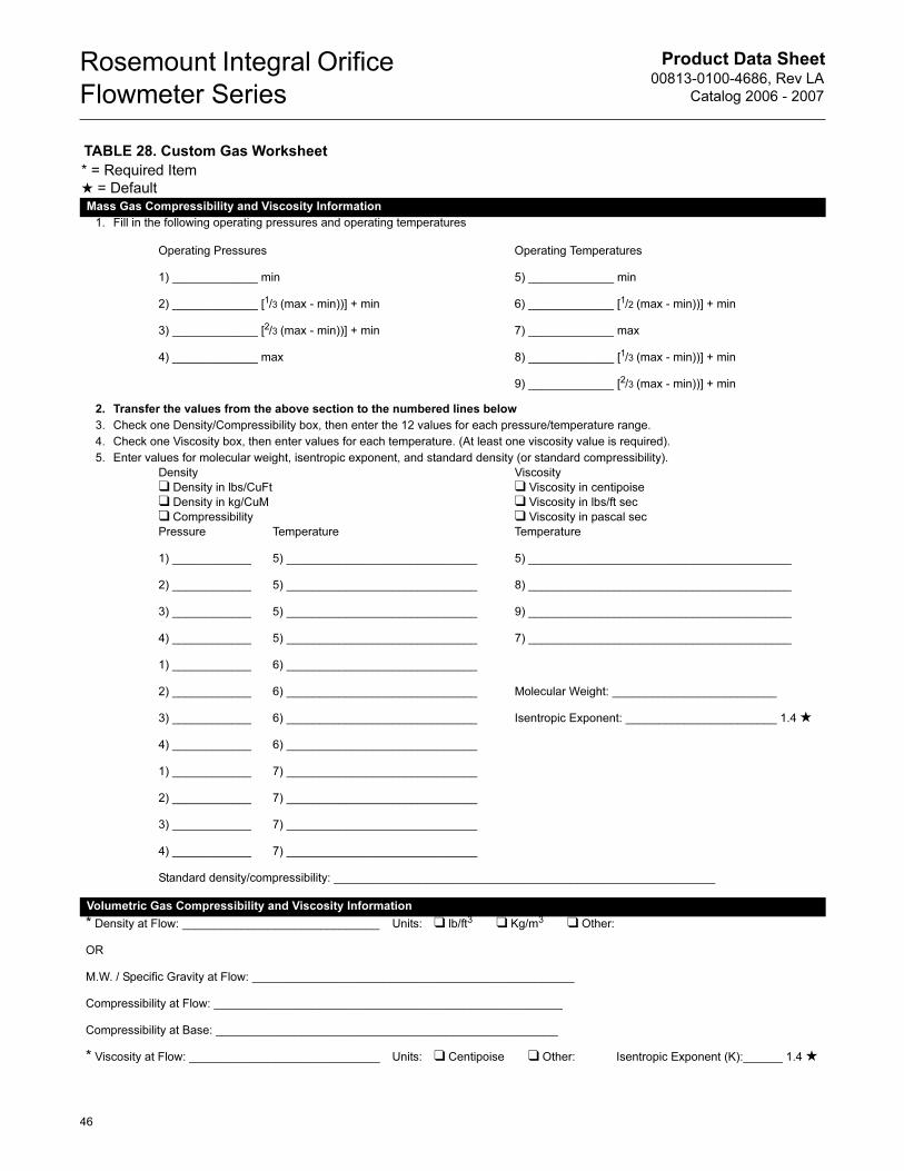
Product Data Sheet00813-0100-4686, Rev LA
Catalog 2006 - 2007
Rosemount Integral Orifice
Flowmeter Series
TABLE 28. Custom Gas Worksheet
* = Required Item
★ = DefaultMass Gas Compressibility and Viscosity Information
1. Fill in the following operating pressures and operating temperatures
Operating Pressures Operating Temperatures
1) _____________ min 5) _____________ min
2) _____________ [1/3 (max - min))] + min 6) _____________ [1/2 (max - min))] + min
3) _____________ [2/3 (max - min))] + min 7) _____________ max
4) _____________ max 8) _____________ [1/3 (max - min))] + min
9) _____________ [2/3 (max - min))] + min
2. Transfer the values from the above section to the numbered lines below
3. Check one Density/Compressibility box, then enter the 12 values for each pressure/temperature range.
4. Check one Viscosity box, then enter values for each temperature. (At least one viscosity value is required).
5. Enter values for molecular weight, isentropic exponent, and standard density (or standard compressibility).
Density
❑ Density in lbs/CuFt
❑ Density in kg/CuM
❑ Compressibility
Viscosity
❑ Viscosity in centipoise
❑ Viscosity in lbs/ft sec
❑ Viscosity in pascal sec
Pressure Temperature Temperature
1) ____________ 5) _____________________________ 5) ________________________________________
2) ____________ 5) _____________________________ 8) ________________________________________
3) ____________ 5) _____________________________ 9) ________________________________________
4) ____________ 5) _____________________________ 7) ________________________________________
1) ____________ 6) _____________________________
2) ____________ 6) _____________________________ Molecular Weight: _________________________
3) ____________ 6) _____________________________ Isentropic Exponent: _______________________ 1.4 ★
4) ____________ 6) _____________________________
1) ____________ 7) _____________________________
2) ____________ 7) _____________________________
3) ____________ 7) _____________________________
4) ____________ 7) _____________________________
Standard density/compressibility: __________________________________________________________
Volumetric Gas Compressibility and Viscosity Information
* Density at Flow: ______________________________ Units: ❑ lb/ft3 ❑ Kg/m3 ❑ Other:
OR
M.W. / Specific Gravity at Flow: _________________________________________________
Compressibility at Flow: _____________________________________________________
Compressibility at Base: ____________________________________________________
* Viscosity at Flow: _____________________________ Units: ❑ Centipoise ❑ Other: Isentropic Exponent (K):______ 1.4 ★
46
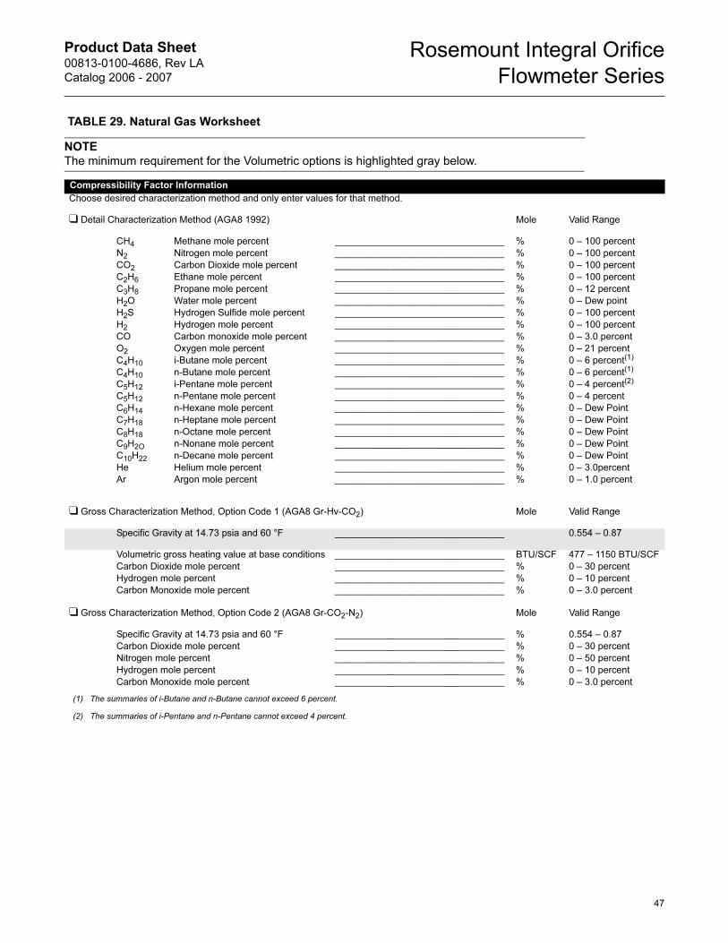
Product Data Sheet00813-0100-4686, Rev LA
Catalog 2006 - 2007
Rosemount Integral Orifice
Flowmeter Series
TABLE 29. Natural Gas Worksheet
NOTE
The minimum requirement for the Volumetric options is highlighted gray below.
Compressibility Factor Information
Choose desired characterization method and only enter values for that method.
❑ Detail Characterization Method (AGA8 1992) Mole Valid Range
CH4
N2
CO2
C2H6
C3H8
H2O
H2S
H2
CO
O2
C4H10
C4H10
C5H12
C5H12
C6H14
C7H18
C8H18
C9H2O
C10H22
He
Ar
Methane mole percent
Nitrogen mole percent
Carbon Dioxide mole percent
Ethane mole percent
Propane mole percent
Water mole percent
Hydrogen Sulfide mole percent
Hydrogen mole percent
Carbon monoxide mole percent
Oxygen mole percent
i-Butane mole percent
n-Butane mole percent
i-Pentane mole percent
n-Pentane mole percent
n-Hexane mole percent
n-Heptane mole percent
n-Octane mole percent
n-Nonane mole percent
n-Decane mole percent
Helium mole percent
Argon mole percent
________________________________
________________________________
________________________________
________________________________
________________________________
________________________________
________________________________
________________________________
________________________________
________________________________
________________________________
________________________________
________________________________
________________________________
________________________________
________________________________
________________________________
________________________________
________________________________
________________________________
________________________________
%
%
%
%
%
%
%
%
%
%
%
%
%
%
%
%
%
%
%
%
%
0 – 100 percent
0 – 100 percent
0 – 100 percent
0 – 100 percent
0 – 12 percent
0 – Dew point
0 – 100 percent
0 – 100 percent
0 – 3.0 percent
0 – 21 percent
0 – 6 percent(1)
0 – 6 percent(1)
0 – 4 percent(2)
0 – 4 percent
0 – Dew Point
0 – Dew Point
0 – Dew Point
0 – Dew Point
0 – Dew Point
0 – 3.0percent
0 – 1.0 percent
(1) The summaries of i-Butane and n-Butane cannot exceed 6 percent.
(2) The summaries of i-Pentane and n-Pentane cannot exceed 4 percent.
❑ Gross Characterization Method, Option Code 1 (AGA8 Gr-Hv-CO2) Mole Valid Range
Specific Gravity at 14.73 psia and 60 °F ________________________________ 0.554 – 0.87
Volumetric gross heating value at base conditions
Carbon Dioxide mole percent
Hydrogen mole percent
Carbon Monoxide mole percent
________________________________
________________________________
________________________________
________________________________
BTU/SCF
%
%
%
477 – 1150 BTU/SCF
0 – 30 percent
0 – 10 percent
0 – 3.0 percent
❑ Gross Characterization Method, Option Code 2 (AGA8 Gr-CO2-N2) Mole Valid Range
Specific Gravity at 14.73 psia and 60 °F
Carbon Dioxide mole percent
Nitrogen mole percent
Hydrogen mole percent
Carbon Monoxide mole percent
________________________________
________________________________
________________________________
________________________________
________________________________
%
%
%
%
%
0.554 – 0.87
0 – 30 percent
0 – 50 percent
0 – 10 percent
0 – 3.0 percent
47

Product Data Sheet00813-0100-4686, Rev LA
Catalog 2006 - 2007
Rosemount Integral Orifice
Flowmeter Series
Notes
48

Product Data Sheet00813-0100-4686, Rev LA
Catalog 2006 - 2007
Rosemount Integral Orifice
Flowmeter Series
49

Product Data Sheet00813-0100-4686, Rev LA
Catalog 2006 - 2007
Rosemount Integral Orifice
Flowmeter Series
Rosemount, the Rosemount logotype, ProPlate, Mass ProPlate, and Annubar are registered trademarks of Rosemount Inc. MultiVariable (MV) and Tri-Loop are trademarks of Rosemount Inc. Pentium is a registered trademark of the Intel Corporation. Microsoft, Windows, and Windows NT are registered trademarks of the Microsoft Corporation. Hastelloy is a registered trademark of Haynes International. Monel and Inconel are registered trademarks of International Nickel Co. HART is a registered trademark of the HART Communication Foundation. Teflon is a
registered trademark of E.I. du Pont de Nemours & Co. All other marks are the property of their respective owners.© 2006 Rosemount Inc. All rights reserved.
¢00813-0100-4686v¤
Emerson Process ManagementEmerson Process Management Heath PlaceBognor RegisWest Sussex PO22 9SHEnglandT 44 (0) 1243 863121F 44 (0) 1243 867554
Emerson Process Management Asia Pacific Private Limited1 Pandan CrescentSingapore 128461T (65) 6777 8211F (65) 6777 [email protected]
Rosemount Inc.8200 Market BoulevardChanhassen, MN USA 55317T (US) (800) 999-9307T (Intnl) (952) 906-8888F (952) 949-7001
www.rosemount.com