Embed Size (px)
Citation preview
Product Data Sheet00813-0100-4810, Rev JA
December 2008
Rosemount Compact Orifice
Flowmeter Series
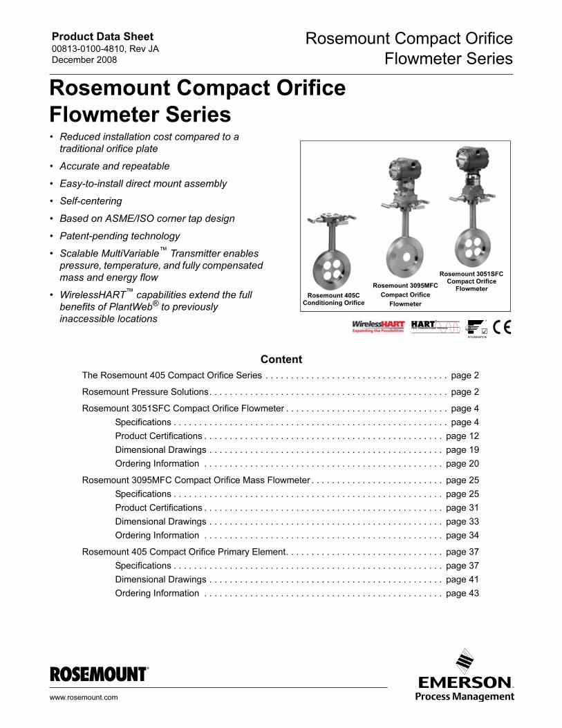
Rosemount Compact Orifice
Flowmeter Series
• Reduced installation cost compared to atraditional orifice plate
• Accurate and repeatable
• Easy-to-install direct mount assembly
• Self-centering
• Based on ASME/ISO corner tap design
• Patent-pending technology
• Scalable MultiVariable™ Transmitter enables
pressure, temperature, and fully compensated
mass and energy flow
• WirelessHART™ capabilities extend the full
benefits of PlantWeb® to previously
inaccessible locations
Rosemount 3051SFC Compact Orifice
FlowmeterRosemount 3095MFC
Compact Orifice
Flowmeter
Rosemount 405C Conditioning Orifice
www.ro
Content
The Rosemount 405 Compact Orifice Series . . . . . . . . . . . . . . . . . . . . . . . . . . . . . . . . . . . . page 2
Rosemount Pressure Solutions. . . . . . . . . . . . . . . . . . . . . . . . . . . . . . . . . . . . . . . . . . . . . . . page 2
Rosemount 3051SFC Compact Orifice Flowmeter . . . . . . . . . . . . . . . . . . . . . . . . . . . . . . . . page 4
Specifications . . . . . . . . . . . . . . . . . . . . . . . . . . . . . . . . . . . . . . . . . . . . . . . . . . . . . . page 4
Product Certifications . . . . . . . . . . . . . . . . . . . . . . . . . . . . . . . . . . . . . . . . . . . . . . . page 12
Dimensional Drawings . . . . . . . . . . . . . . . . . . . . . . . . . . . . . . . . . . . . . . . . . . . . . . page 19
Ordering Information . . . . . . . . . . . . . . . . . . . . . . . . . . . . . . . . . . . . . . . . . . . . . . . page 20
Rosemount 3095MFC Compact Orifice Mass Flowmeter . . . . . . . . . . . . . . . . . . . . . . . . . . page 25
Specifications . . . . . . . . . . . . . . . . . . . . . . . . . . . . . . . . . . . . . . . . . . . . . . . . . . . . . page 25
Product Certifications . . . . . . . . . . . . . . . . . . . . . . . . . . . . . . . . . . . . . . . . . . . . . . . page 31
Dimensional Drawings . . . . . . . . . . . . . . . . . . . . . . . . . . . . . . . . . . . . . . . . . . . . . . page 33
Ordering Information . . . . . . . . . . . . . . . . . . . . . . . . . . . . . . . . . . . . . . . . . . . . . . . page 34
Rosemount 405 Compact Orifice Primary Element. . . . . . . . . . . . . . . . . . . . . . . . . . . . . . . page 37
Specifications . . . . . . . . . . . . . . . . . . . . . . . . . . . . . . . . . . . . . . . . . . . . . . . . . . . . . page 37
Dimensional Drawings . . . . . . . . . . . . . . . . . . . . . . . . . . . . . . . . . . . . . . . . . . . . . . page 41
Ordering Information . . . . . . . . . . . . . . . . . . . . . . . . . . . . . . . . . . . . . . . . . . . . . . . page 43
semount.com
Product Data Sheet00813-0100-4810, Rev JA
December 2008
Rosemount Compact Orifice
Flowmeter Series
2
The Rosemount 405 Compact Orifice Series
Best-in-Class Integrated DP Flowmeters
By integrating Rosemount pressure transmitters with the 405
Compact Orifice Series primary element, Rosemount provides the
highest performing DP Flowmeters. This fully integrated flowmeter
eliminates the need for fittings, tubing, valves, adapters,
manifolds, and mounting brackets, thereby reducing welding and
installation time.
Less Expensive than an Orifice Plate Installation
Direct mounting minimizes total installed cost by reducing
engineering, procurement, labor, and material expenditures while
offering unsurpassed utility.
Direct Mount
A 3-valve isolation manifold and 1-in (25 mm) thick wafer-style
body allows direct mounting while eliminating field connections
between the process and the differential pressure-measuring
device. The integral configuration results in a robust, inexpensive,
and easy-to-install assembly.
Accurate and Repeatable
The 405C Conditioning Orifice is ideal for limited pipe run
measurements in gas, liquid, or steam applications (8-in. (200
mm) nominal diameter and smaller lines). The 405C Conditioning
Orifice delivers consistent and accurate measurements one would
expect from traditional orifice plate technology.
Centering Mechanism
Improper centering of any orifice type device can cause an error of
up to ±5% in small line sizes. A centering mechanism independent
of flange rating is standard with the 405 Compact Orifice Series.
Based on ASME/ISO Corner Tap Design
The incorporation of design features from proven standards results
in a product that performs in a predictable manner and operates
on well-known principles.
Advanced PlantWeb® Functionality
Rosemount orifice flowmeters power PlantWeb
through a scalable architecture, advanced
diagnostics, and MultiVariable capabilities. This
reduces operational and maintenance
expenditures while improving throughput and
utilities management.
Rosemount Pressure SolutionsRosemount 3051S Series of Instrumentation
Highest performing scalable pressure, flow and level
measurement solutions drive better plant efficiency and more
productivity. Innovative features include wireless, advanced
diagnostics, and multivariable technologies.
Rosemount 3095 Mass Flow Transmitter
Accurately measures differential pressure, static pressure and
process temperature to dynamically calculate fully compensated
mass flow.
Rosemount 305, 306 and 304 Manifolds
Factory-assembled, calibrated and seal-tested
transmitter-to-manifold assemblies reduce installation costs.
Rosemount 1199 Diaphragm Seals
Provides reliable, remote measurements of process pressure and
protects the transmitter from hot, corrosive, or viscous fluids.
Orifice Plate Primary Element Systems: Rosemount 1495 and
1595 Orifice Plates, 1496 Flange Unions and 1497 Meter
Sections
A comprehensive offering of orifice plates, flange unions and
meter sections that are easy to specify and order. The 1595
Conditioning Orifice provides superior performance in tight fit
applications.
Rosemount 3051SFA Annubar® Flowmeters,
Rosemount 3095MFA Annubar Flowmeters, and
Rosemount 485 Annubar Flowmeter Series
The state-of-the-art, fifth generation Rosemount 485 Annubar
combined with the Rosemount MultiVariable transmitter
technology creates an accurate, repeatable and dependable
insertion-type flowmeter.
Rosemount 3051SFC Compact Orifice Flowmeters,
Rosemount 3095MFC Compact Orifice Flowmeters, and
Rosemount 405 Compact Orifice Flowmeter Series
Compact Orifice Flowmeters can be installed between existing
flanges, up to a Class 600 (PN100) rating. A conditioning orifice
plate version offers installation in tight fit applications requiring
only two diameters of straight run upstream after a flow
disturbance.
Rosemount 3051SFP Integral Orifice Flowmeters,
Rosemount 3095MFP Integral Orifice Flowmeters, and
Rosemount 1195 Integral Orifice Flowmeter Series
These integral orifice flowmeters eliminate the inaccuracies that
become more pronounced in small orifice line installations. The
completely assembled, ready to install flowmeters reduce cost and
simplify installation.
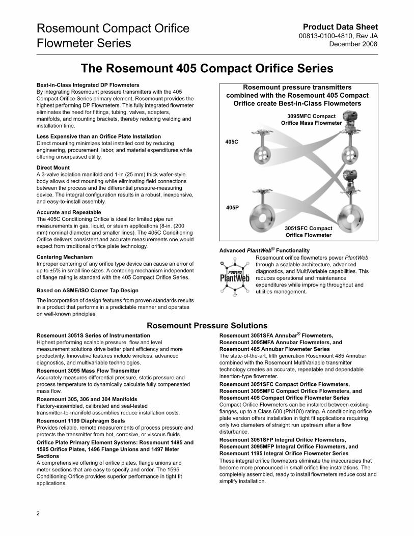
Rosemount pressure transmitters
combined with the Rosemount 405 Compact
Orifice create Best-in-Class Flowmeters
3051SFC Compact
Orifice Flowmeter
3095MFC Compact
Orifice Mass Flowmeter
405C
405P
Product Data Sheet00813-0100-4810, Rev JA
December 2008
Rosemount Compact Orifice
Flowmeter Series
405 Compact Orifice Series Selection Guide
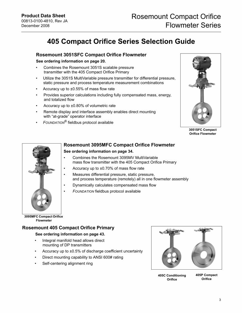
Rosemount 3051SFC Compact Orifice Flowmeter
See ordering information on page 20.
• Combines the Rosemount 3051S scalable pressure transmitter with the 405 Compact Orifice Primary
• Utilize the 3051S MultiVariable pressure transmitter for differential pressure, static pressure and process temperature measurement combinations
• Accuracy up to ±0.55% of mass flow rate
• Provides superior calculations including fully compensated mass, energy, and totalized flow
• Accuracy up to ±0.80% of volumetric rate
• Remote display and interface assembly enables direct mountingwith “at-grade” operator interface
• FOUNDATION® fieldbus protocol available
Rosemount 3095MFC Compact Orifice Flowmeter
See ordering information on page 34.
• Combines the Rosemount 3095MV MultiVariablemass flow transmitter with the 405 Compact Orifice Primary
• Accuracy up to ±0.70% of mass flow rate
• Measures differential pressure, static pressure, and process temperature (remotely) all in one flowmeter assembly
• Dynamically calculates compensated mass flow
• FOUNDATION fieldbus protocol available
Rosemount 405 Compact Orifice Primary
See ordering information on page 43.
• Integral manifold head allows direct mounting of DP transmitters
• Accuracy up to ±0.5% of discharge coefficient uncertainty
• Direct mounting capability to ANSI 600# rating
• Self-centering alignment ring
3095MFC Compact Orifice
Flowmeter
405C Conditioning
Orifice
3051SFC Compact
Orifice Flowmeter
405P Compact
Orifice
3
Product Data Sheet00813-0100-4810, Rev JA
December 2008
Rosemount Compact Orifice
Flowmeter Series
Rosemount 3051SFC Compact Orifice Flowmeter
SPECIFICATIONS
Performance
System Reference Accuracy
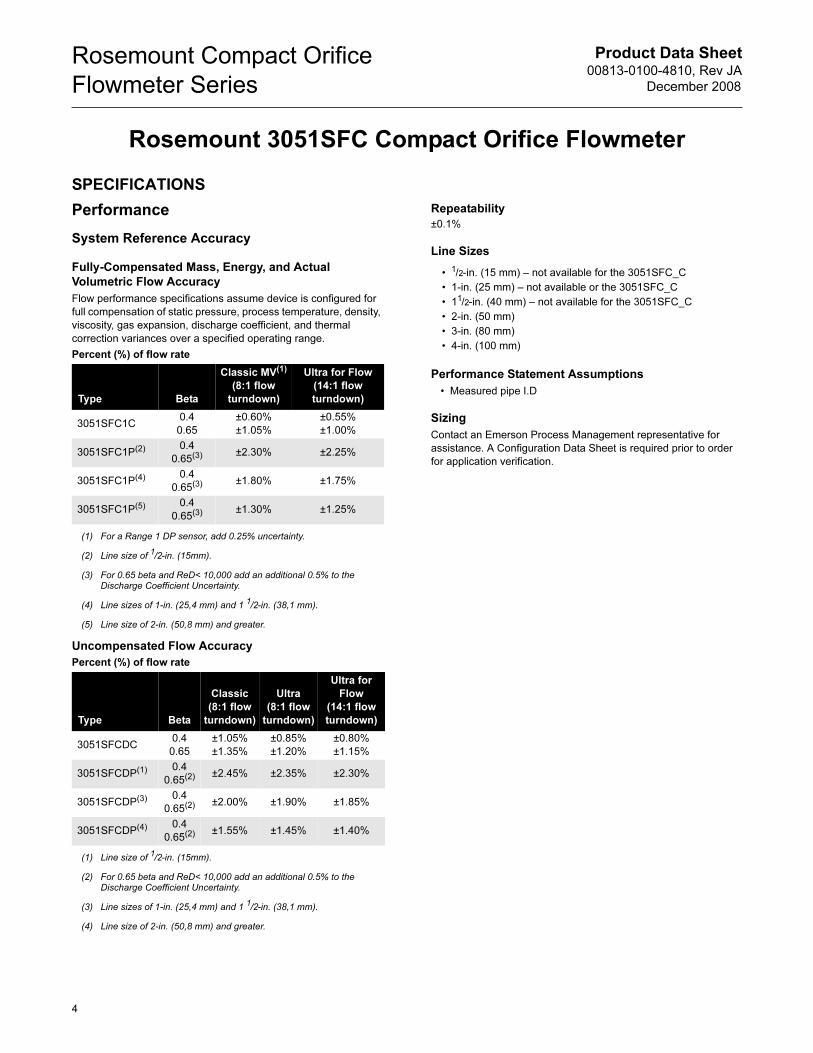
Fully-Compensated Mass, Energy, and Actual
Volumetric Flow Accuracy
Flow performance specifications assume device is configured for
full compensation of static pressure, process temperature, density,
viscosity, gas expansion, discharge coefficient, and thermal
correction variances over a specified operating range.
Percent (%) of flow rate
Uncompensated Flow Accuracy
Percent (%) of flow rate
Repeatability
±0.1%
Line Sizes
Performance Statement Assumptions
• Measured pipe I.D
Sizing
Contact an Emerson Process Management representative for
assistance. A Configuration Data Sheet is required prior to order
for application verification.
Type Beta
Classic MV(1)
(8:1 flow
turndown)
(1) For a Range 1 DP sensor, add 0.25% uncertainty.
Ultra for Flow
(14:1 flow
turndown)
3051SFC1C0.4
0.65
±0.60%
±1.05%
±0.55%
±1.00%
3051SFC1P(2)
(2) Line size of 1/2-in. (15mm).
0.4
0.65(3)
(3) For 0.65 beta and ReD< 10,000 add an additional 0.5% to the Discharge Coefficient Uncertainty.
±2.30% ±2.25%
3051SFC1P(4)
(4) Line sizes of 1-in. (25,4 mm) and 1 1/2-in. (38,1 mm).
0.4
0.65(3) ±1.80% ±1.75%
3051SFC1P(5)
(5) Line size of 2-in. (50,8 mm) and greater.
0.4
0.65(3) ±1.30% ±1.25%
Type Beta
Classic
(8:1 flow
turndown)
Ultra
(8:1 flow
turndown)
Ultra for
Flow
(14:1 flow
turndown)
3051SFCDC0.4
0.65
±1.05%
±1.35%
±0.85%
±1.20%
±0.80%
±1.15%
3051SFCDP(1)
(1) Line size of 1/2-in. (15mm).
0.4
0.65(2)
(2) For 0.65 beta and ReD< 10,000 add an additional 0.5% to the Discharge Coefficient Uncertainty.
±2.45% ±2.35% ±2.30%
3051SFCDP(3)
(3) Line sizes of 1-in. (25,4 mm) and 1 1/2-in. (38,1 mm).
0.4
0.65(2) ±2.00% ±1.90% ±1.85%
3051SFCDP(4)
(4) Line size of 2-in. (50,8 mm) and greater.
0.4
0.65(2) ±1.55% ±1.45% ±1.40%
• 1/2-in. (15 mm) – not available for the 3051SFC_C
• 1-in. (25 mm) – not available or the 3051SFC_C
• 11/2-in. (40 mm) – not available for the 3051SFC_C
• 2-in. (50 mm)
• 3-in. (80 mm)
• 4-in. (100 mm)
4
Product Data Sheet00813-0100-4810, Rev JA
December 2008
Rosemount Compact Orifice
Flowmeter Series
Functional
Service
• Liquid
• Gas
• Steam
4–20 mA/HART®
Zero and Span Adjustment
Zero and span values can be set anywhere within the range.
Span must be greater than or equal to the minimum span.
Output
Two-wire 4–20 mA is user-selectable for linear or square root
output. Digital process variable superimposed on 4–20 mA
signal, available to any host that conforms to the HART protocol.
Power Supply
External power supply required.
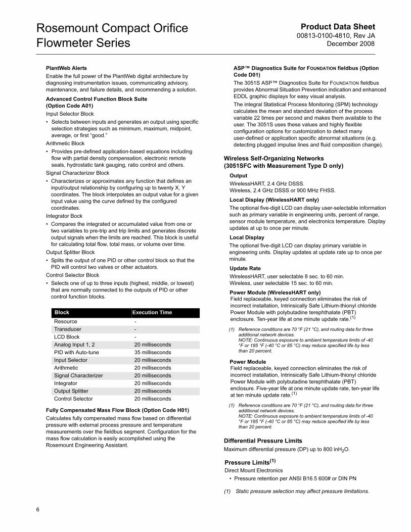
• 3051SFC with Measurement Type D (4–20 mA):
10.5 to 42.4 V dc with no load
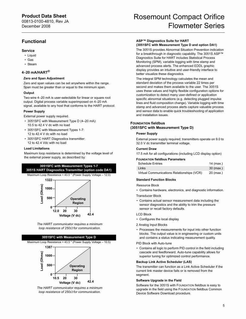
• 3051SFC with Measurement Types 1-7:
12 to 42.4 V dc with no load
• 3051SFC HART Diagnostics transmitter:
12 to 42.4 Vdc with no load
Load Limitations
Maximum loop resistance is determined by the voltage level of
the external power supply, as described by:
ASP™ Diagnostics Suite for HART
(3051SFC with Measurement Type D and option DA1)
The 3051S provides Abnormal Situation Prevention indication
for a breakthrough in diagnostic capability. The 3051S ASP™
Diagnostics Suite for HART includes Statistical Process
Monitoring (SPM), variable logging with time stamp and
advanced process alerts. The enhanced EDDL graphic
display provides an intuitive and user-friendly interface to
better visualize these diagnostics.
The integral SPM technology calculates the mean and
standard deviation of the process variable 22 times per
second and makes them available to the user. The 3051S
uses these values and highly flexible configuration options for
customization to detect many user-defined or application
specific abnormal situations (e.g. detecting plugged impulse
lines and fluid composition change). Variable logging with time
stamp and advanced process alerts capture valuable process
and sensor data to enable quick troubleshooting of application
and installation issues.
FOUNDATION fieldbus
(3051SFC with Measurement Type D)
Power Supply
External power supply required; transmitters operate on 9.0 to
32.0 V dc transmitter terminal voltage.
Current Draw
17.5 mA for all configurations (including LCD display option)
FOUNDATION fieldbus Parameters
Standard Function Blocks
Resource Block
• Contains hardware, electronics, and diagnostic information.
Transducer Block
• Contains actual sensor measurement data including the
sensor diagnostics and the ability to trim the pressure
sensor or recall factory defaults.
LCD Block
• Configures the local display.
2 Analog Input Blocks
• Processes the measurements for input into other function
blocks. The output value is in engineering or custom units
and contains a status indicating measurement quality.
PID Block with Auto-tune
• Contains all logic to perform PID control in the field including
cascade and feedforward. Auto-tune capability allows for
superior tuning for optimized control performance.
Backup Link Active Scheduler (LAS)
The transmitter can function as a Link Active Scheduler if the
current link master device fails or is removed from the
segment.
Software Upgrade in the Field
Software for the 3051S with FOUNDATION fieldbus is easy to
upgrade in the field using the FOUNDATION fieldbus Common
Device Software Download procedure.
3051SFC with Measurement Types 1-7
3051S HART Diagnostics Transmitter (option code DA1)
Maximum Loop Resistance = 43.5 * (Power Supply Voltage – 12.0)
The HART communicator requires a minimum
loop resistance of 250Ω for communication.
3051SFC with Measurement Type D
Maximum Loop Resistance = 43.5 * (Power Supply Voltage – 10.5)
The HART communicator requires a minimum
loop resistance of 250Ω for communication.
Voltage (V dc)
Lo
ad
(O
hm
s)
Operating
Region
1322
1000
500
012.0 20 30
42.4
Voltage (V dc)
Lo
ad
(O
hm
s)
Operating
Region
1387
1000
500
010.5 20 30
42.4
Schedule Entries 14 (max.)
Links 30 (max.)
Virtual Communications Relationships (VCR) 20 (max.)
5
Product Data Sheet00813-0100-4810, Rev JA
December 2008
Rosemount Compact Orifice
Flowmeter Series
PlantWeb Alerts
Enable the full power of the PlantWeb digital architecture by
diagnosing instrumentation issues, communicating advisory,
maintenance, and failure details, and recommending a solution.
Advanced Control Function Block Suite
(Option Code A01)
Input Selector Block
• Selects between inputs and generates an output using specific
selection strategies such as minimum, maximum, midpoint,
average, or first “good.”
Arithmetic Block
• Provides pre-defined application-based equations including
flow with partial density compensation, electronic remote
seals, hydrostatic tank gauging, ratio control and others.
Signal Characterizer Block
• Characterizes or approximates any function that defines an
input/output relationship by configuring up to twenty X, Y
coordinates. The block interpolates an output value for a given
input value using the curve defined by the configured
coordinates.
Integrator Bock
• Compares the integrated or accumulated value from one or
two variables to pre-trip and trip limits and generates discrete
output signals when the limits are reached. This block is useful
for calculating total flow, total mass, or volume over time.
Output Splitter Block
• Splits the output of one PID or other control block so that the
PID will control two valves or other actuators.
Control Selector Block
• Selects one of up to three inputs (highest, middle, or lowest)
that are normally connected to the outputs of PID or other
control function blocks.
Fully Compensated Mass Flow Block (Option Code H01)
Calculates fully compensated mass flow based on differential
pressure with external process pressure and temperature
measurements over the fieldbus segment. Configuration for the
mass flow calculation is easily accomplished using the
Rosemount Engineering Assistant.
ASP™ Diagnostics Suite for FOUNDATION fieldbus (Option
Code D01)
The 3051S ASP™ Diagnostics Suite for FOUNDATION fieldbus
provides Abnormal Situation Prevention indication and enhanced
EDDL graphic displays for easy visual analysis.
The integral Statistical Process Monitoring (SPM) technology
calculates the mean and standard deviation of the process
variable 22 times per second and makes them available to the
user. The 3051S uses these values and highly flexible
configuration options for customization to detect many
user-defined or application specific abnormal situations (e.g.
detecting plugged impulse lines and fluid composition change).
Wireless Self-Organizing Networks
(3051SFC with Measurement Type D only)
Output
WirelessHART, 2.4 GHz DSSS.
Wireless, 2.4 GHz DSSS or 900 MHz FHSS.
Local Display (WirelessHART only)
The optional five-digit LCD can display user-selectable information
such as primary variable in engineering units, percent of range,
sensor module temperature, and electronics temperature. Display
updates at up to once per minute.
Local Display
The optional five-digit LCD can display primary variable in
engineering units. Display updates at update rate up to once per
minute.
Update Rate
WirelessHART, user selectable 8 sec. to 60 min.
Wireless, user selectable 15 sec. to 60 min.
Power Module (WirelessHART only)
Power Module
Differential Pressure Limits
Maximum differential pressure (DP) up to 800 inH2O.
Block Execution Time
Resource -
Transducer -
LCD Block -
Analog Input 1, 2 20 milliseconds
PID with Auto-tune 35 milliseconds
Input Selector 20 milliseconds
Arithmetic 20 milliseconds
Signal Characterizer 20 milliseconds
Integrator 20 milliseconds
Output Splitter 20 milliseconds
Control Selector 20 milliseconds
Field replaceable, keyed connection eliminates the risk of
incorrect installation, Intrinsically Safe Lithium-thionyl chloride
Power Module with polybutadine terephthalate (PBT)
enclosure. Ten-year life at one minute update rate.(1)
(1) Reference conditions are 70 °F (21 °C), and routing data for three additional network devices.NOTE: Continuous exposure to ambient temperature limits of -40 °F or 185 °F (-40 °C or 85 °C) may reduce specified life by less than 20 percent.
Field replaceable, keyed connection eliminates the risk of
incorrect installation, Intrinsically Safe Lithium-thionyl chloride
Power Module with polybutadine terephthalate (PBT)
enclosure. Five-year life at one minute update rate, ten-year life
at ten minute update rate.(1)
(1) Reference conditions are 70 °F (21 °C), and routing data for three additional network devices.NOTE: Continuous exposure to ambient temperature limits of -40 °F or 185 °F (-40 °C or 85 °C) may reduce specified life by less than 20 percent.
Pressure Limits(1)
Direct Mount Electronics
• Pressure retention per ANSI B16.5 600# or DIN PN
(1) Static pressure selection may affect pressure limitations.
6
Product Data Sheet00813-0100-4810, Rev JA
December 2008
Rosemount Compact Orifice
Flowmeter Series
7
Static Pressure Limit
3051SFC with Measurement Types 3, 4, 7, and D
Operates within specifications between static line pressures of
0.5 psia and 3626 psig;
4500 psig (310,3 bar) for option code P9
6092 psig (420 bar) for option code P0 (Classic only)
Range 1: 0.5 psia to 2000 psig (0,03 to137,90 bar)
3051SFC with Measurement Types 1, 2, 5, and 6
Operates within 0.5 psia (0,03 bar) and the values in the table
below:
Burst Pressure Limits
Coplanar or traditional process flange
10000 psig (689,5 bar).
Overpressure Limits
Transmitters withstand the following limits without damage:
3051SFC with Measurement Types 3, 4, 7, and D
Range 1: 2000 psig (137,9 bar)
Ranges 2–3: 3626 psig (250,0 bar)
3051SFC with Measurement Types 1, 2, 5, and 6
Flowmeter Overpressure Limits(1)
Process Temperature Limits
Direct Mount Transmitter
• -40 to 450 °F (-40 to 232 °C)
Remote Mount Transmitter
• -148 to 850 °F (-100 to 454 °C) – Stainless Steel
Transmitter Temperature Limits
Ambient
Storage
Vibration Limits
Qualified per IEC61298-3 (1998) for field with high vibration level
or pipeline with high vibration level (10-60Hz 0.21mm
displacement peak amplitude / 60 - 500Hz 3g).
The weight and length of the transmitter assembly shall not
exceed 5.8 lbs and 7.75-in.
Humidity Limits
• 0–100% relative humidity
Turn-On Time
Damping
Analog output response to a step change is user-selectable from 0
to 60 seconds for one time constant. For 3051SFC with
measurement types 1-7, differential pressure (DP), static pressure
(AP/GP), process temperature (PT), Mass Flow, and Energy Flow
can be individually adjusted. This software damping is in addition
to sensor module response time.
Failure Mode Alarm
HART 4-20mA (output option code A)
If self-diagnostics detect a gross transmitter failure, the analog
signal will be driven offscale to alert the user. Rosemount
standard (default), NAMUR, and custom alarm levels are
available (see Table 1).
High or low alarm signal is software-selectable or
hardware-selectable via the optional switch (option D1).
Static
Pressure
Differential Pressure
Range 1 Range 2 Range 3
Range D, J
GP/AP
800 psi
(57,91 bar)
800 psi
(57,91 bar)
800 psi
(57,91 bar)
Range E, K
GP/AP
2000 psi
(137,9 bar)
3626 psi
(250 bar)
3626 psi
(250 bar)
Static
Pressure
Differential Pressure
Range 1 Range 2 Range 3
Range D, J
GP/AP
1600 psi
(110,3 bar)
1600 psi
(110,3 bar)
1600 psi
(110,3 bar)
Range E, K
GP/AP
2000 psi
(137,9 bar)
3626 psi
(250 bar)
3626 psi
(250 bar)
Standard(1)
(1) Carbon Steel and Stainless Steel Ratings are measured in psig (bar).
Type
Carbon Steel
Rating
Stainless
Steel Rating
ANSI/ASME Class 150 285 (20) 275 (19)
ANSI/ASME Class 300 740 (51) 720 (50)
ANSI/ASME Class 600 1480 (102) 1440 (99)
At 100 °F (38 °C), the rating decreases with increasing temperature.
DIN PN 10/40 580 (40) 580 (40)
DIN PN 10/16 232 (16) 232 (16)
DIN PN 25/40 580 (40) 580 (40)
At 248 °F (120 °C), the rating decreases with increasing temperature.
–40 to 185 °F (–40 to 85 °C)
With LCD display(1): –40 to 175 °F (–40 to 80 °C)
With option code P0: –4 to 185 °F (–20 to 85 °C)
With Inert Fill(2): 0 to 185 °F (-17 to 85 °C)
(1) LCD display may not be readable and LCD updates will be slower at temperatures below -4 °F (-20 °C).
(2) Inert fill temperature limits only apply to 3051SFC with Measurement Types 1, 2, 5, and 6.
–50 to 230 °F (–46 to 110 °C)
With LCD display: –40 to 185 °F (–40 to 85 °C)
With wireless output (code X): –40 to 185 °F (–40 to 85 °C)
With Inert Fill(1): 0 to 185 °F (-17 to 85 °C)
(1) Inert fill temperature limits only apply to 3051SFC with Measurement Types 1, 2, 5, and 6.
Performance within specifications less than 5 seconds for
3051SFC with Measurement Types 1-7 and 2 seconds for
3051SFC with Measurement Type D (typical) after power is
applied to the transmitter.
TABLE 1. Alarm Configuration
High Alarm Low Alarm
Default ≥ 21.75 mA ≤ 3.75 mA
NAMUR compliant(1)
(1) Analog output levels are compliant with NAMUR recommendation NE 43, see option codes C4 or C5.
≥ 22.5 mA ≤ 3.6 mA
Custom levels(2)(3)
(2) Low alarm must be 0.1 mA less than low saturation and high alarm must be 0.1 mA greater than high saturation.
(3) Not available with the SIS Safety Transmitter (option QT).
20.2 - 23.0 mA 3.6 - 3.8 mA
Product Data Sheet00813-0100-4810, Rev JA
December 2008
Rosemount Compact Orifice
Flowmeter Series
Safety-Certified Transmitter Failure Values
(3051SFC with Measurement Type D Only)
Dynamic Performance(1)
Safety accuracy: 2.0%(1)
Safety response time: 1.5 seconds
(1) A 2% variation of the transmitter mA output is allowed before a safety trip. Trip values in the DCS or safety logic solver should be derated by 2%.
(1)
(1) Does not apply to wireless output code X. See “Wireless Self-Organizing Networks (3051SFC with Measurement Type D only)” on page 6 for wireless transmit rate.
4 - 20 mA (HART)(2)
(2) Dead time and update rate apply to all models and ranges; analog output only
Fieldbus protocol(3)(4)
(3) Transmitter fieldbus output only, segment macro-cycle not included.
(4) FOUNDATION fieldbus not applicable with 3051SFC with Measurement Types 1-7.
Typical Transmitter Response Time
Total Response Time (Td + Tc)(5)
3051SFC with Measurement
Types 1-7:
DP Range 1:
DP Range 2:
DP Range 3:
AP & GP:
Type D(6):
DP Ranges 2-3:
DP Range 1:
(5) Nominal total response time at 75 °F (24 °C) reference conditions.
(6) For option code DA1, add 45 milliseconds (nominal) to 4-20 mA (HART) total response time values.
310 milliseconds
170 milliseconds
155 milliseconds
240 milliseconds
100 milliseconds
255 milliseconds
152 milliseconds
307 milliseconds
Dead Time (Td)
3051SFC with Measurement
Types 1-7:
DP:
AP & GP:
Type D(7):
DP:
Types 1, 3, 5, and 7 only:
Process Temp RTD Interface:
(7) For option code DA1, dead time (Td) is 90 milliseconds (nominal).
100 milliseconds
140 milliseconds
45 milliseconds (nominal)
1 second
97 milliseconds
Update Rate
3051SFC with Measurement
Types 1-7:
DP:
Type D:
DP:
Types 1, 2, 5, and 6 only:
AP & GP:
Types 1, 3, 5, and 7 only:
Process Temp RTD Interface:
Types 1-4 Calculated Variables:
Mass or Volumetric Flow Rate:
Energy Flow Rate:
Totalized Flow:
22 times per second
22 times per second
11 times per second
1 time per second
22 times per second
22 times per second
1 time per second
22 times per second
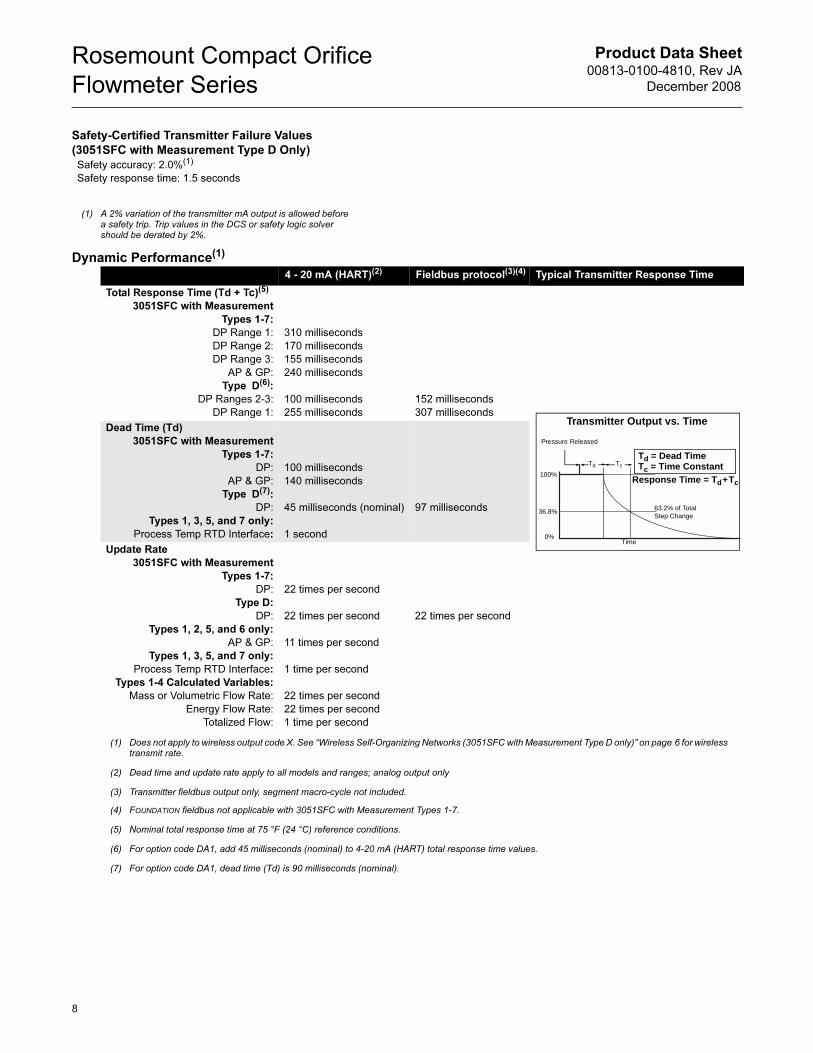
TcTd
Td = Dead TimeTc = Time Constant
Pressure Released
Response Time = Td+Tc
63.2% of TotalStep Change
Time0%
100%
36.8%
Transmitter Output vs. Time
8
Product Data Sheet00813-0100-4810, Rev JA
December 2008
Rosemount Compact Orifice
Flowmeter Series
9
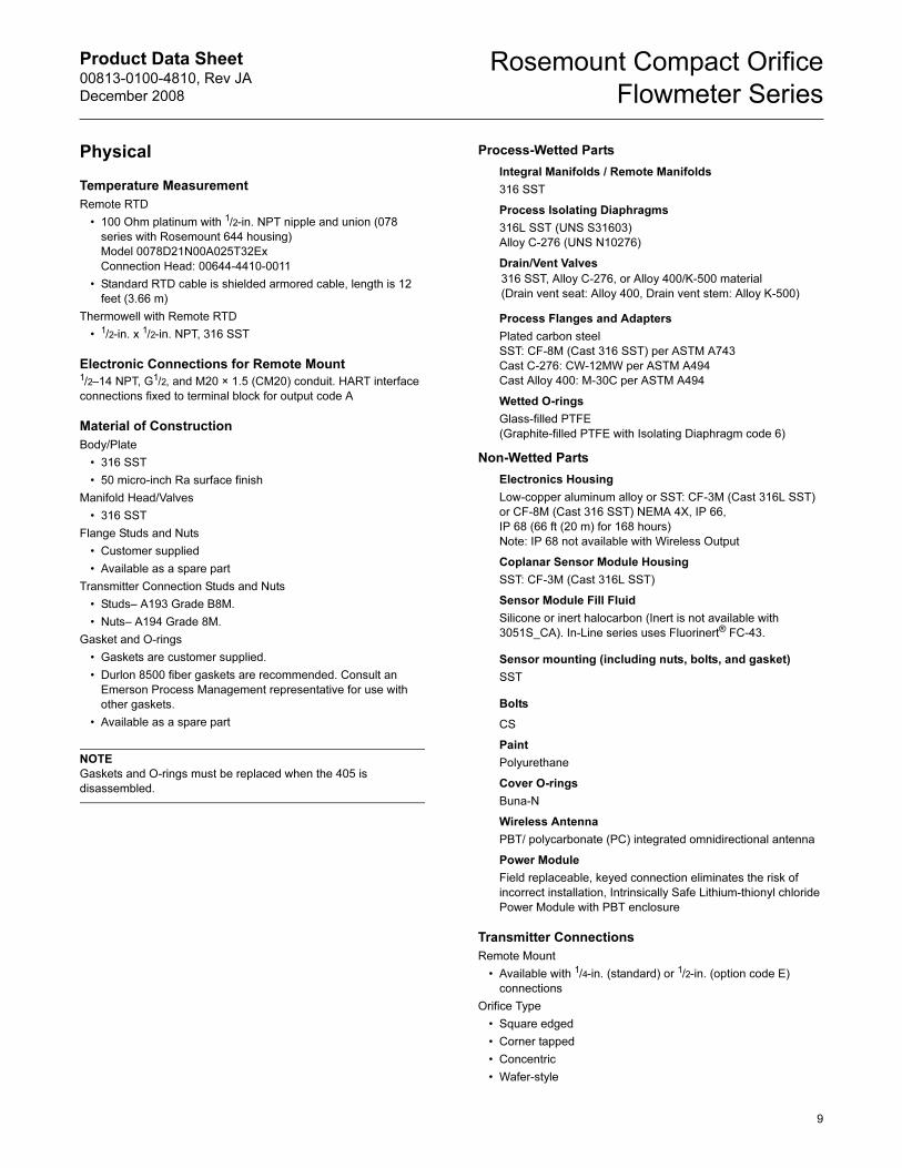
Physical
Temperature Measurement
Remote RTD
• 100 Ohm platinum with 1/2-in. NPT nipple and union (078
series with Rosemount 644 housing)
Model 0078D21N00A025T32Ex
Connection Head: 00644-4410-0011
• Standard RTD cable is shielded armored cable, length is 12
feet (3.66 m)
Thermowell with Remote RTD
• 1/2-in. x 1/2-in. NPT, 316 SST
Electronic Connections for Remote Mount1/2–14 NPT, G1/2, and M20 × 1.5 (CM20) conduit. HART interface
connections fixed to terminal block for output code A
Material of Construction
Body/Plate
• 316 SST
• 50 micro-inch Ra surface finish
Manifold Head/Valves
• 316 SST
Flange Studs and Nuts
• Customer supplied
• Available as a spare part
Transmitter Connection Studs and Nuts
• Studs– A193 Grade B8M.
• Nuts– A194 Grade 8M.
Gasket and O-rings
• Gaskets are customer supplied.
• Durlon 8500 fiber gaskets are recommended. Consult an
Emerson Process Management representative for use with
other gaskets.
• Available as a spare part
NOTE
Gaskets and O-rings must be replaced when the 405 is
disassembled.
Process-Wetted Parts
Integral Manifolds / Remote Manifolds
316 SST
Process Isolating Diaphragms
316L SST (UNS S31603)
Alloy C-276 (UNS N10276)
Drain/Vent Valves
Process Flanges and Adapters
Plated carbon steel
SST: CF-8M (Cast 316 SST) per ASTM A743
Cast C-276: CW-12MW per ASTM A494
Cast Alloy 400: M-30C per ASTM A494
Wetted O-rings
Glass-filled PTFE
(Graphite-filled PTFE with Isolating Diaphragm code 6)
Non-Wetted Parts
Electronics Housing
Low-copper aluminum alloy or SST: CF-3M (Cast 316L SST)
or CF-8M (Cast 316 SST) NEMA 4X, IP 66,
IP 68 (66 ft (20 m) for 168 hours)
Note: IP 68 not available with Wireless Output
Coplanar Sensor Module Housing
SST: CF-3M (Cast 316L SST)
Sensor Module Fill Fluid
Silicone or inert halocarbon (Inert is not available with
3051S_CA). In-Line series uses Fluorinert® FC-43.
Sensor mounting (including nuts, bolts, and gasket)
SST
Bolts
CS
Paint
Polyurethane
Cover O-rings
Buna-N
Wireless Antenna
PBT/ polycarbonate (PC) integrated omnidirectional antenna
Power Module
Field replaceable, keyed connection eliminates the risk of
incorrect installation, Intrinsically Safe Lithium-thionyl chloride
Power Module with PBT enclosure
Transmitter Connections
Remote Mount
• Available with 1/4-in. (standard) or 1/2-in. (option code E)
connections
Orifice Type
• Square edged
• Corner tapped
• Concentric
• Wafer-style
316 SST, Alloy C-276, or Alloy 400/K-500 material
(Drain vent seat: Alloy 400, Drain vent stem: Alloy K-500)
Product Data Sheet00813-0100-4810, Rev JA
December 2008
Rosemount Compact Orifice
Flowmeter Series
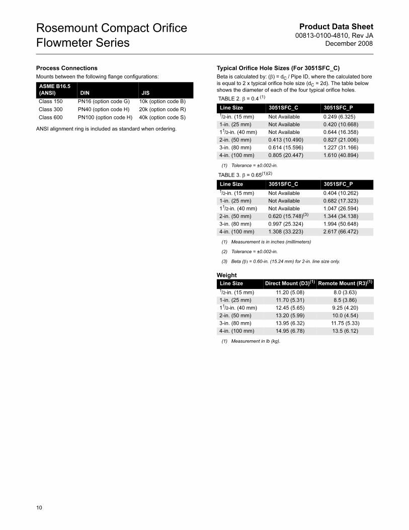
Process Connections
Mounts between the following flange configurations:
ANSI alignment ring is included as standard when ordering.
Typical Orifice Hole Sizes (For 3051SFC_C)
Beta is calculated by: (β) = dC / Pipe ID, where the calculated bore
is equal to 2 x typical orifice hole size (dC = 2d). The table below
shows the diameter of each of the four typical orifice holes.
Weight
ASME B16.5
(ANSI) DIN JIS
Class 150
Class 300
Class 600
PN16 (option code G)
PN40 (option code H)
PN100 (option code H)
10k (option code B)
20k (option code R)
40k (option code S)
TABLE 2. β = 0.4 (1)
(1) Tolerance = ±0.002-in.
Line Size 3051SFC_C 3051SFC_P
1/2-in. (15 mm) Not Available 0.249 (6.325)
1-in. (25 mm) Not Available 0.420 (10.668)
11/2-in. (40 mm) Not Available 0.644 (16.358)
2-in. (50 mm) 0.413 (10.490) 0.827 (21.006)
3-in. (80 mm) 0.614 (15.596) 1.227 (31.166)
4-in. (100 mm) 0.805 (20.447) 1.610 (40.894)
TABLE 3. β = 0.65(1)(2)
(1) Measurement is in inches (millimeters)
(2) Tolerance = ±0.002-in.
Line Size 3051SFC_C 3051SFC_P
1/2-in. (15 mm) Not Available 0.404 (10.262)
1-in. (25 mm) Not Available 0.682 (17.323)
11/2-in. (40 mm) Not Available 1.047 (26.594)
2-in. (50 mm) 0.620 (15.748)(3)
(3) Beta (β) = 0.60-in. (15.24 mm) for 2-in. line size only.
1.344 (34.138)
3-in. (80 mm) 0.997 (25.324) 1.994 (50.648)
4-in. (100 mm) 1.308 (33.223) 2.617 (66.472)
Line Size Direct Mount (D3)(1)
(1) Measurement in lb (kg).
Remote Mount (R3)(1)
1/2-in. (15 mm) 11.20 (5.08) 8.0 (3.63)
1-in. (25 mm) 11.70 (5.31) 8.5 (3.86)
11/2-in. (40 mm) 12.45 (5.65) 9.25 (4.20)
2-in. (50 mm) 13.20 (5.99) 10.0 (4.54)
3-in. (80 mm) 13.95 (6.32) 11.75 (5.33)
4-in. (100 mm) 14.95 (6.78) 13.5 (6.12)
10
Product Data Sheet00813-0100-4810, Rev JA
December 2008
Rosemount Compact Orifice
Flowmeter Series
11
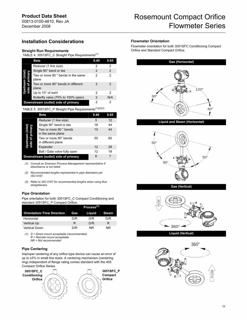
Installation Considerations
Straight Run Requirements
Pipe Orientation
Pipe orientation for both 3051SFC_C Compact Conditioning and
standard 3051SFC_P Compact Orifice.
Pipe Centering
Improper centering of any orifice type device can cause an error of
up to ±5% in small line sizes. A centering mechanism (centering
ring) independent of flange rating comes standard with the 405
Compact Orifice Series.
Flowmeter Orientation
Flowmeter orientation for both 3051SFC Conditioning Compact
Orifice and Standard Compact Orifice.
TABLE 4. 3051SFC_C Straight Pipe Requirements(1)
Beta 0.40 0.65
Up
str
ea
m (
inle
t)
sid
e o
f p
rim
ary
Reducer (1 line size) 2 2
Single 90° bend or tee 2 2
Two or more 90 ° bends in the same
plane
2 2
Two or more 90° bends in different
plane
2 2
Up to 10° of swirl 2 2
Butterfly valve (75% to 100% open) 2 N/A
Downstream (outlet) side of primary 2 2
TABLE 5. 3051SFC_P Straight Pipe Requirements(1)(2)(3)
(1) Consult an Emerson Process Management representative if disturbance is not listed.
Beta 0.40 0.65
(2)(3)
(2) Recommended lengths represented in pipe diameters per ISO 5167.
(3) Refer to ISO 5167 for recommended lengths when using flow straighteners.
Reducer (1 line size) 5 12
Single 90° bend or tee 16 44
Two or more 90 ° bends
in the same plane
10 44
Two or more 90° bends
in different plane
50 60
Expander 12 28
Ball / Gate valve fully open 12 18
Downstream (outlet) side of primary 6 7
Orientation/ Flow Direction
Process(1)
(1) D = Direct mount acceptable (recommended)R = Remote mount acceptableNR = Not recommended
Gas Liquid Steam
Horizontal D/R D/R D/R
Vertical Up R D/R R
Vertical Down D/R NR NR
Up
str
ea
m (
inle
t)
sid
e o
f p
rim
ary
3051SFC_P
Compact
Orifice
3051SFC_C
Conditioning
Orifice
Gas (Horizontal)
Liquid and Steam (Horizontal)
Gas (Vertical)
Liquid (Vertical)
30°
120°
30°
50°
80°50°
360°
FLO
W
360°
FLO
W
Product Data Sheet00813-0100-4810, Rev JA
December 2008
Rosemount Compact Orifice
Flowmeter Series
12
Rosemount 3051SFC with Measurement Types 1-7
Certifications
Approved Manufacturing LocationsRosemount Inc. — Chanhassen, Minnesota USA
Emerson Process Management GmbH & Co. — Wessling,
Germany
Emerson Process Management Asia Pacific Private Limited —
Singapore
Beijing Rosemount Far East Instrument Co., LTD — Beijing, China
Ordinary Location Certification for FMAs standard, the transmitter has been examined and tested to
determine that the design meets basic electrical, mechanical, and
fire protection requirements by FM, a nationally recognized testing
laboratory (NRTL) as accredited by the Federal Occupational
Safety and Health Administration (OSHA).
European Directive Information
The EC declaration of conformity for all applicable European
directives for this product can be found at www.rosemount.com. A
hard copy may be obtained by contacting an Emerson Process
Management representative.
ATEX Directive (94/9/EC)
Emerson Process Management complies with the
ATEX Directive.
European Pressure Equipment Directive (PED) (97/23/EC)
Models with Differential Pressure Ranges = 2 to 5 inclusive with
Static Pressure = Range 4 only. P9 and P0 options also.
All other Model 3051SMV Pressure Transmitters
— Sound Engineering Practice
Transmitter Attachments: Diaphragm Seal - Process Flange -
Manifold — Sound Engineering Practice
Primary Elements, Flowmeter
— See appropriate Primary Element QIG
Electro Magnetic Compatibility (EMC) (2004/108/EC)
EN 61326-1:2006 and EN 61326-2-3:2006
Hazardous Locations Certifications
North American Certifications
FM Approvals
E5 Explosion-proof for Class I, Division 1, Groups B, C, and D;
dust-ignition proof for Class II and Class III, Division 1,
Groups E, F, and G; hazardous locations; enclosure Type
4X, conduit seal not required.
I5 Intrinsically Safe for use in Class I, Division 1, Groups A, B,
C, and D; Class II, Division 1, Groups E, F, and G; Class III,
Division 1; Class I, Zone 0 AEx ia IIC when connected in
accordance with Rosemount drawing 03151-1206;
Non-incendive for Class I, Division 2, Groups A, B, C, and D
Enclosure Type 4X
For entity parameters see control drawing 03151-1206.
Canadian Standards Association (CSA)
All CSA hazardous approved transmitters are certified per
ANSI/ISA 12.27.01-2003.
E6 Explosion-proof for Class I, Division 1, Groups B, C, and D;
Dust-Ignition-Proof for Class II and Class III, Division 1,
Groups E, F, and G; suitable for Class I, Division 2, Groups
A, B, C, and D, CSA Enclosure Type 4X; conduit seal not
required.
I6 Intrinsically Safe for Class I, Division 1, Groups A, B, C, and
D when connected in accordance with Rosemount drawings
03151-1207;
For entity parameters see control drawing 03151-1207.
European Certifications
I1 ATEX Intrinsic Safety
Certificate No.: 08ATEX0064X II 1G
Ex ia IIC T4 (Ta = -60 °C to 70 °C) -HART
1180
Special conditions for safe use (x)
The apparatus is not capable of withstanding the 500V test
as defined in Clause 6.3.12 of EN 60079-11. This must be
considered during installation.
N1 ATEX Type n
Certificate No.: Baseefa 08ATEX0065X II 3 G
Ex nA nL IIC T4 (Ta = -40 °C TO 70 °C)
Ui = 45 Vdc max
IP66
Special conditions for safe use (x)
The apparatus is not capable of withstanding the 500V
insulation test required by Clause 6.8.1 of EN 60079-15. This
must be taken into account when installing the apparatus.
ND ATEX Dust
Certificate No.: BAS01ATEX1303X II 1 D
T105°C (-20 °C ≤ Tamb ≤ 85 °C)
Vmax = 42.4 volts max
A = 24 mA
IP66
1180
Input Parameters
Loop / Power Groups
Ui = 30 V HART
Ii = 300 mA HART
Pi = 1.0 W HART
Ci = 14.8 nF HART
Li = 0 HART
Product Data Sheet00813-0100-4810, Rev JA
December 2008
Rosemount Compact Orifice
Flowmeter Series
13
Special conditions for safe use (x)
1. The user must ensure that the maximum rated voltage
and current (42.4 volts, 22 milliampere, DC) are not
exceeded. All connections to other apparatus or
associated apparatus shall have control over this voltage
and current equivalent to a category “ib” circuit according
to EN 60079-11.
2. Cable entries must be used which maintain the ingress
protection of the enclosure to at least IP66.
3. Unused cable entries must be filled with suitable blanking
plugs which maintain the ingress protection of the
enclosure to at least IP66.
4. Cable entries and blanking plugs must be suitable for the
ambient range of the apparatus and capable of
withstanding a 7J impact test.
5. The 3051SMV must be securely screwed in place to
maintain the ingress protection of the enclosure. (The
3051SMV SuperModule must be properly assembled to
the 3051SMV housing to maintain ingress protection.)
E1 ATEX Flameproof
Certificate No.: KEMA 00ATEX2143X II 1/2 G
Ex d IIC T6 (-50 °C ≤ Tamb ≤ 65 °C)
Ex d IIC T5 (-50 °C ≤ Tamb ≤ 80 °C)
Vmax = 42.4V
1180
Special conditions for safe use (x)
1. Appropriate ex d blanking plugs, cable glands, and wiring
needs to be suitable for a temperature of 90 °C.
2. This device contains a thin wall diaphragm. Installation,
maintenance and use shall take into account the
environmental conditions to which the diaphragm will be
subjected. The manufacturer’s instructions for
maintenance shall be followed in detail to assure safety
during its expected lifetime.
3. The 3051SMV does not comply with the requirements of
IEC 60079-1 Clause 5.2, Table 2 for all joints. Contact
Emerson Process Management for information on the
dimensions of flameproof joints.
Japanese Certifications
E4 TIIS Flameproof
Consult factory for availability
I4 TIIS Intrinsically Safe
Consult factory for availability
China (NEPSI) Certifications
E3 China Flameproof
Ex d II B+H2T3~T5
I3 China Intrinsic Safety
Ex ia IIC T3/T4
IECEx Certifications
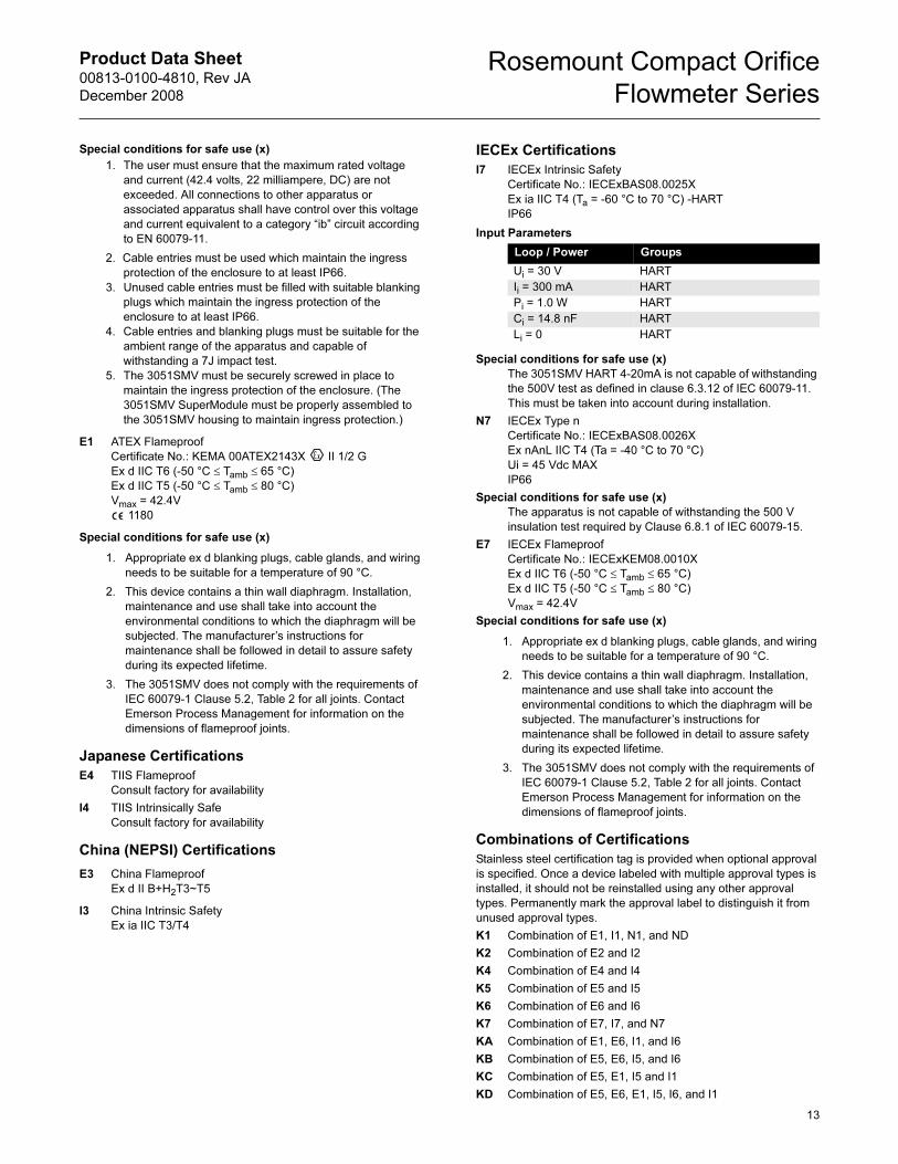
I7 IECEx Intrinsic Safety
Certificate No.: IECExBAS08.0025X
Ex ia IIC T4 (Ta = -60 °C to 70 °C) -HART
IP66
Special conditions for safe use (x)
The 3051SMV HART 4-20mA is not capable of withstanding
the 500V test as defined in clause 6.3.12 of IEC 60079-11.
This must be taken into account during installation.
N7 IECEx Type n
Certificate No.: IECExBAS08.0026X
Ex nAnL IIC T4 (Ta = -40 °C to 70 °C)
Ui = 45 Vdc MAX
IP66
Special conditions for safe use (x)
The apparatus is not capable of withstanding the 500 V
insulation test required by Clause 6.8.1 of IEC 60079-15.
E7 IECEx Flameproof
Certificate No.: IECExKEM08.0010X
Ex d IIC T6 (-50 °C ≤ Tamb ≤ 65 °C)
Ex d IIC T5 (-50 °C ≤ Tamb ≤ 80 °C)
Vmax = 42.4V
Special conditions for safe use (x)
1. Appropriate ex d blanking plugs, cable glands, and wiring
needs to be suitable for a temperature of 90 °C.
2. This device contains a thin wall diaphragm. Installation,
maintenance and use shall take into account the
environmental conditions to which the diaphragm will be
subjected. The manufacturer’s instructions for
maintenance shall be followed in detail to assure safety
during its expected lifetime.
3. The 3051SMV does not comply with the requirements of
IEC 60079-1 Clause 5.2, Table 2 for all joints. Contact
Emerson Process Management for information on the
dimensions of flameproof joints.
Combinations of Certifications
Stainless steel certification tag is provided when optional approval
is specified. Once a device labeled with multiple approval types is
installed, it should not be reinstalled using any other approval
types. Permanently mark the approval label to distinguish it from
unused approval types.
K1 Combination of E1, I1, N1, and ND
K2 Combination of E2 and I2
K4 Combination of E4 and I4
K5 Combination of E5 and I5
K6 Combination of E6 and I6
K7 Combination of E7, I7, and N7
KA Combination of E1, E6, I1, and I6
KB Combination of E5, E6, I5, and I6
KC Combination of E5, E1, I5 and I1
KD Combination of E5, E6, E1, I5, I6, and I1
Input Parameters
Loop / Power Groups
Ui = 30 V HART
Ii = 300 mA HART
Pi = 1.0 W HART
Ci = 14.8 nF HART
Li = 0 HART
Product Data Sheet00813-0100-4810, Rev JA
December 2008
Rosemount Compact Orifice
Flowmeter Series
14
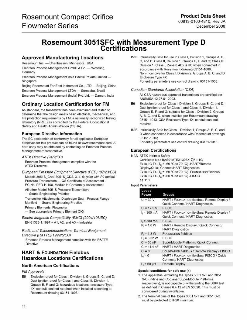
Rosemount 3051SFC with Measurement Type D Certifications
Approved Manufacturing LocationsRosemount Inc. — Chanhassen, Minnesota USA
Emerson Process Management GmbH & Co. — Wessling,
Germany
Emerson Process Management Asia Pacific Private Limited —
Singapore
Beijing Rosemount Far East Instrument Co., LTD — Beijing, China
Emerson Process Management LTDA — Sorocaba, Brazil
Emerson Process Management (India) Pvt. Ltd. — Daman, India
Ordinary Location Certification for FMAs standard, the transmitter has been examined and tested to
determine that the design meets basic electrical, mechanical, and
fire protection requirements by FM, a nationally recognized testing
laboratory (NRTL) as accredited by the Federal Occupational
Safety and Health Administration (OSHA).
European Directive InformationThe EC declaration of conformity for all applicable European
directives for this product can be found at www.rosemount.com. A
hard copy may be obtained by contacting an Emerson Process
Management representative.
ATEX Directive (94/9/EC)
Emerson Process Management complies with the
ATEX Directive.
European Pressure Equipment Directive (PED) (97/23/EC)
Models 3051S_CA4; 3051S_CD2, 3, 4, 5; (also with P9 option)
Pressure Transmitters — QS Certificate of Assessment -
EC No. PED-H-100, Module H Conformity Assessment
All other Model 3051S Pressure Transmitters
— Sound Engineering Practice
Transmitter Attachments: Diaphragm Seal - Process Flange -
Manifold — Sound Engineering Practice
Primary Elements, Flowmeter
— See appropriate Primary Element QIG
Electro Magnetic Compatibility (EMC) (2004/108/EC)
EN 61326-1:1997 + A1, A2, and A3 – Industrial
Radio and Telecommunications Terminal Equipment
Directive (R&TTE)(1999/5/EC)
Emerson Process Management complies with the R&TTE
Directive.
HART & FOUNDATION Fieldbus Hazardous Locations Certifications
North American Certifications
FM Approvals
E5 Explosion-proof for Class I, Division 1, Groups B, C, and D;
Dust Ignition-proof for Class II and Class III, Division 1,
Groups E, F, and G; hazardous locations; enclosure Type
4X, conduit seal not required when installed according to
Rosemount drawing 03151-1003.
I5/IE Intrinsically Safe for use in Class I, Division 1, Groups A, B,
C, and D; Class II, Division 1, Groups E, F, and G; Class III,
Division 1; Class I, Zone 0 AEx ia IIC when connected in
accordance with Rosemount drawing 03151-1006;
Non-Incendive for Class I, Division 2, Groups A, B, C, and D
Enclosure Type 4X
For entity parameters see control drawing 03151-1006.
Canadian Standards Association (CSA)
All CSA hazardous approved transmitters are certified per
ANSI/ISA 12.27.01-2003.
E6 Explosion-proof for Class I, Division 1, Groups B, C, and D;
Dust Ignition-proof for Class II and Class III, Division 1,
Groups E, F, and G; suitable for Class I, Division 2, Groups
A, B, C, and D, when installed per Rosemount drawing
03151-1013, CSA Enclosure Type 4X; conduit seal not
required.
I6/IF Intrinsically Safe for Class I, Division 1, Groups A, B, C, and
D when connected in accordance with Rosemount drawings
03151-1016;
For entity parameters see control drawing 03151-1016.
European Certifications
I1/IA ATEX Intrinsic Safety
Certificate No.: BAS01ATEX1303X II 1G
Ex ia IIC T4 (Ta = -60 °C to 70 °C) -HART/Remote
Display/Quick Connect/HART Diagnostics
Ex ia IIC T4 (Ta = -60 °C to 70 °C) -FOUNDATION fieldbus
Ex ia IIC T4 (Ta = -60 °C to 40 °C) -FISCO
1180
Special conditions for safe use (x)
1. The apparatus, excluding the Types 3051 S-T and 3051
S-C (In-line and Coplanar SuperModule Platforms
respectively), is not capable of withstanding the 500V test
as defined in Clause 6.4.12 of EN 50020. This must be
considered during installation.
2. The terminal pins of the Types 3051 S-T and 3051 S-C
must be protected to IP20 minimum.
Input Parameters
Loop /
Power Groups
Ui = 30 V HART / FOUNDATION fieldbus/ Remote Display /
Quick Connect / HART Diagnostics
Ui = 17.5 V FISCO
Ii = 300 mA HART / FOUNDATION fieldbus/ Remote Display /
Quick Connect / HART Diagnostics
Ii = 380 mA FISCO
Pi = 1.0 W HART / Remote Display / Quick Connect /
HART Diagnostics
Pi = 1.3 W FOUNDATION fieldbus
Pi = 5.32 W FISCO
Ci = 30 nF SuperModule Platform / Quick Connect
Ci = 11.4 nF HART / HART Diagnostics
Ci = 0 FOUNDATION fieldbus / Remote Display / FISCO
Li = 0 HART / FOUNDATION fieldbus/ FISCO / Quick
Connect / HART Diagnostics
Li = 60 µH Remote Display
Product Data Sheet00813-0100-4810, Rev JA
December 2008
Rosemount Compact Orifice
Flowmeter Series
15
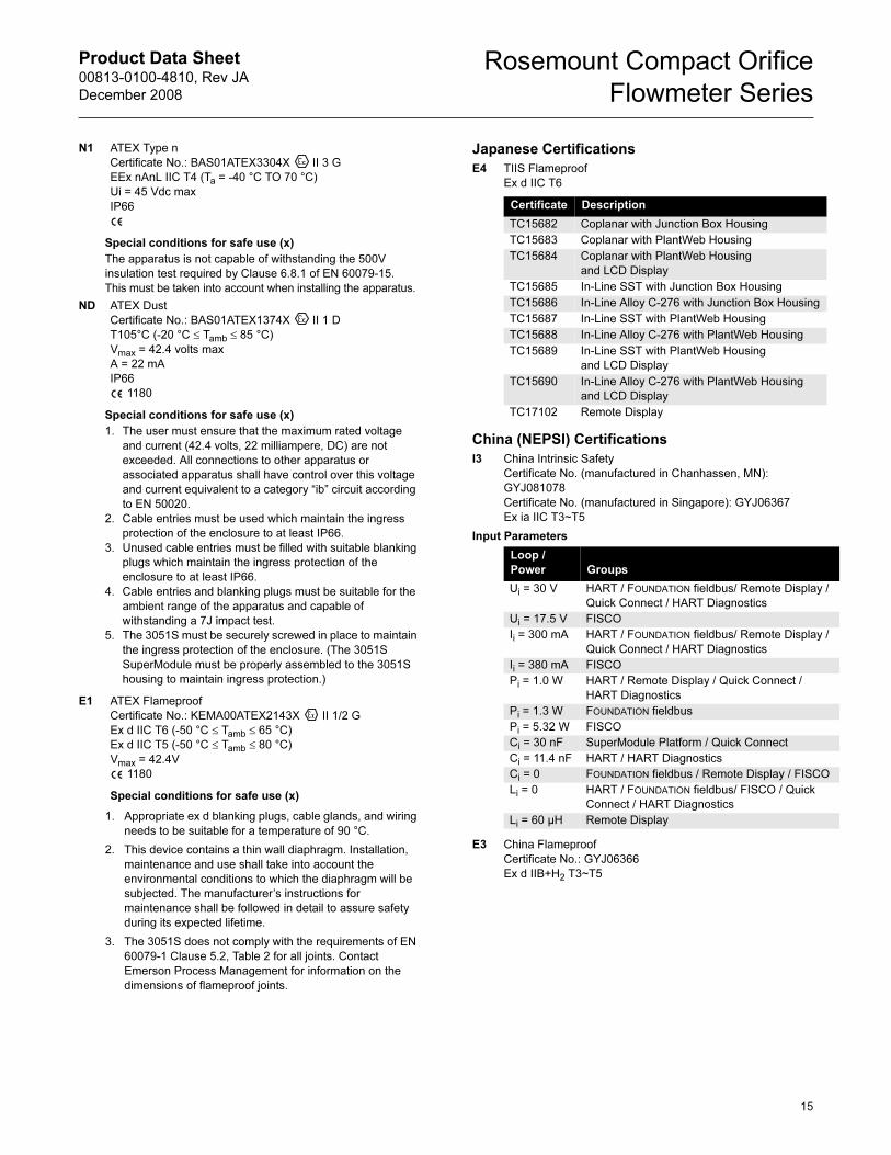
N1 ATEX Type n
Certificate No.: BAS01ATEX3304X II 3 G
EEx nAnL IIC T4 (Ta = -40 °C TO 70 °C)
Ui = 45 Vdc max
IP66
Special conditions for safe use (x)
The apparatus is not capable of withstanding the 500V
insulation test required by Clause 6.8.1 of EN 60079-15.
This must be taken into account when installing the apparatus.
ND ATEX Dust
Certificate No.: BAS01ATEX1374X II 1 D
T105°C (-20 °C ≤ Tamb ≤ 85 °C)
Vmax = 42.4 volts max
A = 22 mA
IP66
1180
Special conditions for safe use (x)
1. The user must ensure that the maximum rated voltage
and current (42.4 volts, 22 milliampere, DC) are not
exceeded. All connections to other apparatus or
associated apparatus shall have control over this voltage
and current equivalent to a category “ib” circuit according
to EN 50020.
2. Cable entries must be used which maintain the ingress
protection of the enclosure to at least IP66.
3. Unused cable entries must be filled with suitable blanking
plugs which maintain the ingress protection of the
enclosure to at least IP66.
4. Cable entries and blanking plugs must be suitable for the
ambient range of the apparatus and capable of
withstanding a 7J impact test.
5. The 3051S must be securely screwed in place to maintain
the ingress protection of the enclosure. (The 3051S
SuperModule must be properly assembled to the 3051S
housing to maintain ingress protection.)
E1 ATEX Flameproof
Certificate No.: KEMA00ATEX2143X II 1/2 G
Ex d IIC T6 (-50 °C ≤ Tamb ≤ 65 °C)
Ex d IIC T5 (-50 °C ≤ Tamb ≤ 80 °C)
Vmax = 42.4V
1180
Special conditions for safe use (x)
1. Appropriate ex d blanking plugs, cable glands, and wiring
needs to be suitable for a temperature of 90 °C.
2. This device contains a thin wall diaphragm. Installation,
maintenance and use shall take into account the
environmental conditions to which the diaphragm will be
subjected. The manufacturer’s instructions for
maintenance shall be followed in detail to assure safety
during its expected lifetime.
3. The 3051S does not comply with the requirements of EN
60079-1 Clause 5.2, Table 2 for all joints. Contact
Emerson Process Management for information on the
dimensions of flameproof joints.
Japanese Certifications
E4 TIIS Flameproof
Ex d IIC T6
China (NEPSI) Certifications
I3 China Intrinsic Safety
Certificate No. (manufactured in Chanhassen, MN):
GYJ081078
Certificate No. (manufactured in Singapore): GYJ06367
Ex ia IIC T3~T5
E3 China Flameproof
Certificate No.: GYJ06366
Ex d IIB+H2 T3~T5
Certificate Description
TC15682 Coplanar with Junction Box Housing
TC15683 Coplanar with PlantWeb Housing
TC15684 Coplanar with PlantWeb Housing
and LCD Display
TC15685 In-Line SST with Junction Box Housing
TC15686 In-Line Alloy C-276 with Junction Box Housing
TC15687 In-Line SST with PlantWeb Housing
TC15688 In-Line Alloy C-276 with PlantWeb Housing
TC15689 In-Line SST with PlantWeb Housing
and LCD Display
TC15690 In-Line Alloy C-276 with PlantWeb Housing
and LCD Display
TC17102 Remote Display
Input Parameters
Loop /
Power Groups
Ui = 30 V HART / FOUNDATION fieldbus/ Remote Display /
Quick Connect / HART Diagnostics
Ui = 17.5 V FISCO
Ii = 300 mA HART / FOUNDATION fieldbus/ Remote Display /
Quick Connect / HART Diagnostics
Ii = 380 mA FISCO
Pi = 1.0 W HART / Remote Display / Quick Connect /
HART Diagnostics
Pi = 1.3 W FOUNDATION fieldbus
Pi = 5.32 W FISCO
Ci = 30 nF SuperModule Platform / Quick Connect
Ci = 11.4 nF HART / HART Diagnostics
Ci = 0 FOUNDATION fieldbus / Remote Display / FISCO
Li = 0 HART / FOUNDATION fieldbus/ FISCO / Quick
Connect / HART Diagnostics
Li = 60 µH Remote Display
Product Data Sheet00813-0100-4810, Rev JA
December 2008
Rosemount Compact Orifice
Flowmeter Series
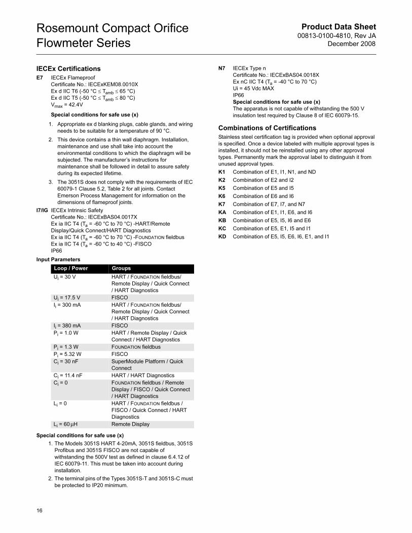
IECEx Certifications
E7 IECEx Flameproof
Certificate No.: IECExKEM08.0010X
Ex d IIC T6 (-50 °C ≤ Tamb ≤ 65 °C)
Ex d IIC T5 (-50 °C ≤ Tamb ≤ 80 °C)
Vmax = 42.4V
Special conditions for safe use (x)
1. Appropriate ex d blanking plugs, cable glands, and wiring
needs to be suitable for a temperature of 90 °C.
2. This device contains a thin wall diaphragm. Installation,
maintenance and use shall take into account the
environmental conditions to which the diaphragm will be
subjected. The manufacturer’s instructions for
maintenance shall be followed in detail to assure safety
during its expected lifetime.
3. The 3051S does not comply with the requirements of IEC
60079-1 Clause 5.2, Table 2 for all joints. Contact
Emerson Process Management for information on the
dimensions of flameproof joints.
I7/IG IECEx Intrinsic Safety
Certificate No.: IECExBAS04.0017X
Ex ia IIC T4 (Ta = -60 °C to 70 °C) -HART/Remote
Display/Quick Connect/HART Diagnostics
Ex ia IIC T4 (Ta = -60 °C to 70 °C) -FOUNDATION fieldbus
Ex ia IIC T4 (Ta = -60 °C to 40 °C) -FISCO
IP66
Special conditions for safe use (x)
1. The Models 3051S HART 4-20mA, 3051S fieldbus, 3051S
Profibus and 3051S FISCO are not capable of
withstanding the 500V test as defined in clause 6.4.12 of
IEC 60079-11. This must be taken into account during
installation.
2. The terminal pins of the Types 3051S-T and 3051S-C must
be protected to IP20 minimum.
N7 IECEx Type n
Certificate No.: IECExBAS04.0018X
Ex nC IIC T4 (Ta = -40 °C to 70 °C)
Ui = 45 Vdc MAX
IP66
Special conditions for safe use (x)
The apparatus is not capable of withstanding the 500 V
insulation test required by Clause 8 of IEC 60079-15.
Combinations of Certifications
Stainless steel certification tag is provided when optional approval
is specified. Once a device labeled with multiple approval types is
installed, it should not be reinstalled using any other approval
types. Permanently mark the approval label to distinguish it from
unused approval types.
K1 Combination of E1, I1, N1, and ND
K2 Combination of E2 and I2
K5 Combination of E5 and I5
K6 Combination of E6 and I6
K7 Combination of E7, I7, and N7
KA Combination of E1, I1, E6, and I6
KB Combination of E5, I5, I6 and E6
KC Combination of E5, E1, I5 and I1
KD Combination of E5, I5, E6, I6, E1, and I1
Input Parameters
Loop / Power Groups
Ui = 30 V HART / FOUNDATION fieldbus/
Remote Display / Quick Connect
/ HART Diagnostics
Ui = 17.5 V FISCO
Ii = 300 mA HART / FOUNDATION fieldbus/
Remote Display / Quick Connect
/ HART Diagnostics
Ii = 380 mA FISCO
Pi = 1.0 W HART / Remote Display / Quick
Connect / HART Diagnostics
Pi = 1.3 W FOUNDATION fieldbus
Pi = 5.32 W FISCO
Ci = 30 nF SuperModule Platform / Quick
Connect
Ci = 11.4 nF HART / HART Diagnostics
Ci = 0 FOUNDATION fieldbus / Remote
Display / FISCO / Quick Connect
/ HART Diagnostics
Li = 0 HART / FOUNDATION fieldbus /
FISCO / Quick Connect / HART
Diagnostics
Li = 60 H Remote Displayµ
16
Product Data Sheet00813-0100-4810, Rev JA
December 2008
Rosemount Compact Orifice
Flowmeter Series
17
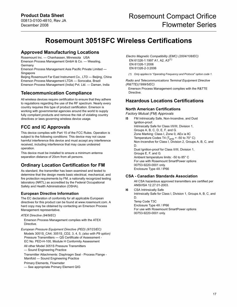
Rosemount 3051SFC Wireless Certifications
Approved Manufacturing LocationsRosemount Inc. — Chanhassen, Minnesota USA
Emerson Process Management GmbH & Co. — Wessling,
Germany
Emerson Process Management Asia Pacific Private Limited —
Singapore
Beijing Rosemount Far East Instrument Co., LTD — Beijing, China
Emerson Process Management LTDA — Sorocaba, Brazil
Emerson Process Management (India) Pvt. Ltd. — Daman, India
Telecommunication Compliance
All wireless devices require certification to ensure that they adhere
to regulations regarding the use of the RF spectrum. Nearly every
country requires this type of product certification. Emerson is
working with governmental agencies around the world to supply
fully compliant products and remove the risk of violating country
directives or laws governing wireless device usage.
FCC and IC ApprovalsThis device complies with Part 15 of the FCC Rules. Operation is
subject to the following conditions: This device may not cause
harmful interference this device and must accept any interference
received, including interference that may cause undesired
operation.
This device must be installed to ensure a minimum antenna
separation distance of 20cm from all persons.
Ordinary Location Certification for FMAs standard, the transmitter has been examined and tested to
determine that the design meets basic electrical, mechanical, and
fire protection requirements by FM, a nationally recognized testing
laboratory (NRTL) as accredited by the Federal Occupational
Safety and Health Administration (OSHA).
European Directive InformationThe EC declaration of conformity for all applicable European
directives for this product can be found at www.rosemount.com. A
hard copy may be obtained by contacting an Emerson Process
Management representative.
ATEX Directive (94/9/EC)
Emerson Process Management complies with the ATEX
Directive.
European Pressure Equipment Directive (PED) (97/23/EC)
Models 3051S_CA4; 3051S_CD2, 3, 4, 5; (also with P9 option)
Pressure Transmitters — QS Certificate of Assessment -
EC No. PED-H-100, Module H Conformity Assessment
All other Model 3051S Pressure Transmitters
— Sound Engineering Practice
Transmitter Attachments: Diaphragm Seal - Process Flange -
Manifold — Sound Engineering Practice
Primary Elements, Flowmeter
— See appropriate Primary Element QIG
Radio and Telecommunications Terminal Equipment Directive
(R&TTE)(1999/5/EC)
Emerson Process Management complies with the R&TTE
Directive.
Hazardous Locations Certifications
North American CertificationsFactory Mutual (FM) Approvals
I5 FM Intrinsically Safe, Non-Incendive, and Dust
Ignition-proof.
Intrinsically Safe for Class I/II/III, Division 1,
Groups A, B, C, D, E, F, and G.
Zone Marking: Class I, Zone 0, AEx ia llC
Temperature Codes T4 (Tamb = -50 to 70° C)
Non-Incendive for Class I, Division 2, Groups A, B, C, and
D.
Dust Ignition-proof for Class II/III, Division 1,
Groups E, F, and G.
Ambient temperature limits: -50 to 85° C
For use with Rosemount SmartPower options
00753-9220-0001 only.
Enclosure Type 4X / IP66
CSA - Canadian Standards Association
All CSA hazardous approved transmitters are certified per
ANSI/ISA 12.27.01-2003.
I6 CSA Intrinsically Safe
Intrinsically Safe for Class I, Division 1, Groups A, B, C, and
D.
Temp Code T3C
Enclosure Type 4X / IP66
For use with Rosemount SmartPower options
00753-9220-0001 only.
Electro Magnetic Compatibility (EMC) (2004/108/EC)
EN 61326-1:1997 A1, A2, A3(1)
EN 61326-1:2006
EN 61326-2-3:2006
(1) Only applies to “Operating Frequency and Protocol” option code 1.
Product Data Sheet00813-0100-4810, Rev JA
December 2008
Rosemount Compact Orifice
Flowmeter Series
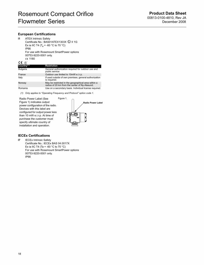
European Certifications
I1 ATEX Intrinsic Safety
Certificate No.: BAS01ATEX1303X II 1G
Ex ia IIC T4 (Ta = -60 °C to 70 °C)
IP66
For use with Rosemount SmartPower options
00753-9220-0001 only.
1180
IECEx Certifications
I7 IECEx Intrinsic Safety
Certificate No.: IECEx BAS 04.0017X
Ex ia IIC T4 (Ta = -60 °C to 70 °C)
For use with Rosemount SmartPower options
00753-9220-0001 only.
IP66
Country(1)
(1) Only applies to “Operating Frequency and Protocol” option code 1.
Restriction
Bulgaria General authorization required for outdoor use and public service
France Outdoor use limited to 10mW e.i.r.p.
Italy If used outside of own premises, general authorization is required.
Norway May be restricted in the geographical area within a radius of 20 km from the center of Ny-Alesund.
Romania Use on a secondary basis. Individual license required.
Radio Power Label (See
Figure 1) indicates output
power configuration of the radio.
Devices with this label are
configured for output power less
than 10 mW e.i.r.p. At time of
purchase the customer must
specify ultimate country of
installation and operation.
(1)
Radio Power Label
Figure 1.
18
Product Data Sheet00813-0100-4810, Rev JA
December 2008
Rosemount Compact Orifice
Flowmeter Series
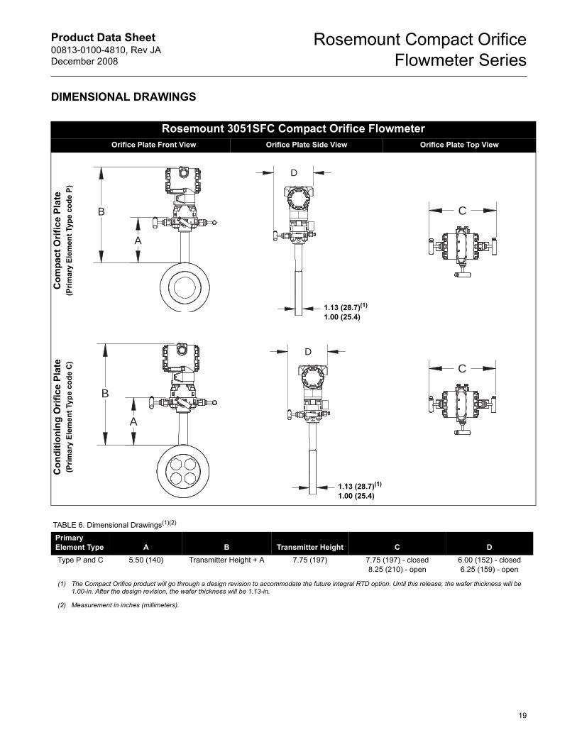
DIMENSIONAL DRAWINGS
Rosemount 3051SFC Compact Orifice Flowmeter
Orifice Plate Front View Orifice Plate Side View Orifice Plate Top View
Co
mp
act
Ori
fice P
late
(Pri
ma
ry E
lem
en
t Ty
pe
co
de
P)
Co
nd
itio
nin
g O
rifi
ce P
late
(Pri
ma
ry E
lem
en
t Ty
pe
co
de
C)
A
B
D
1.13 (28.7)(1)
1.00 (25.4)
C
A
B
D
1.13 (28.7)(1)
1.00 (25.4)
C
TABLE 6. Dimensional Drawings(1)(2)
Primary(1)(2)
Element Type A B Transmitter Height C D
Type P and C 5.50 (140) Transmitter Height + A 7.75 (197) 7.75 (197) - closed
8.25 (210) - open
6.00 (152) - closed
6.25 (159) - open
(1) The Compact Orifice product will go through a design revision to accommodate the future integral RTD option. Until this release, the wafer thickness will be 1.00-in. After the design revision, the wafer thickness will be 1.13-in.
(2) Measurement in inches (millimeters).
19
Product Data Sheet00813-0100-4810, Rev JA
December 2008
Rosemount Compact Orifice
Flowmeter Series
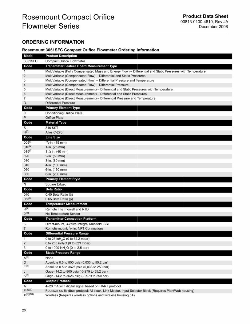
ORDERING INFORMATION
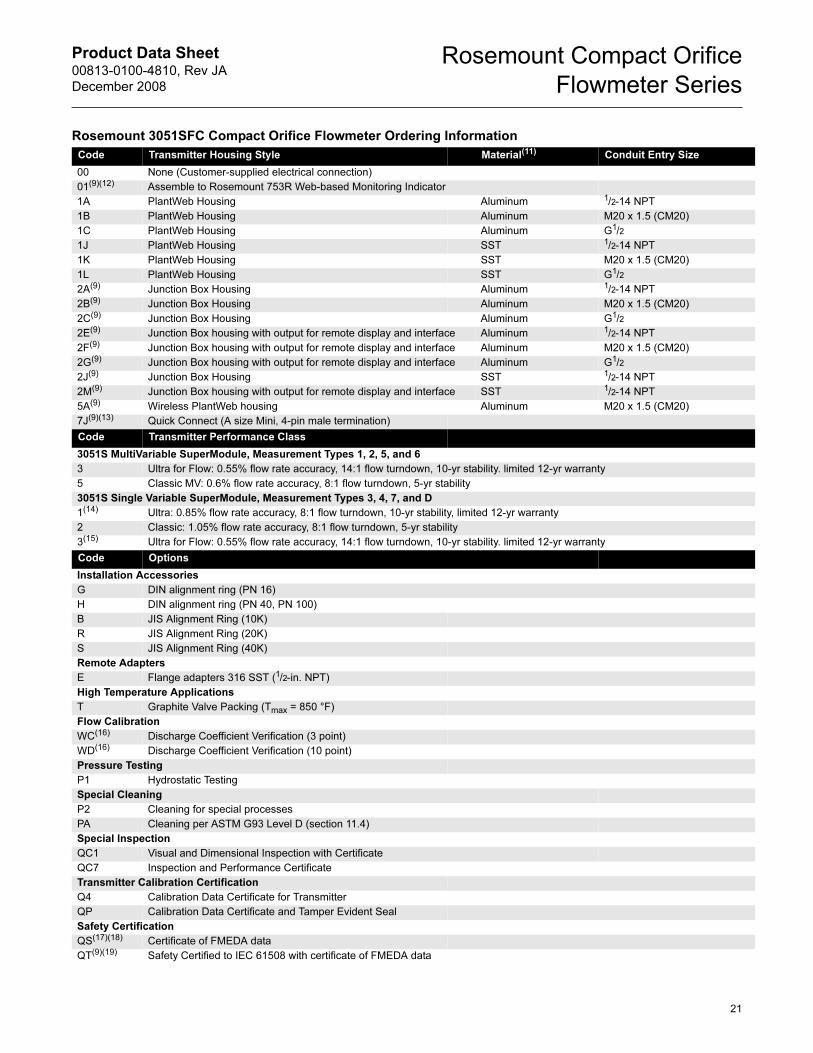
Rosemount 3051SFC Compact Orifice Flowmeter Ordering Information
Model Product Description
3051SFC Compact Orifice Flowmeter
Code Transmitter Feature Board Measurement Type
1 MultiVariable (Fully Compensated Mass and Energy Flow) – Differential and Static Pressures with Temperature
2 MultiVariable (Compensated Flow) – Differential and Static Pressures
3 MultiVariable (Compensated Flow) – Differential Pressure and Temperature
4 MultiVariable (Compensated Flow) – Differential Pressure
5 MultiVariable (Direct Measurement) – Differential and Static Pressures with Temperature
6 MultiVariable (Direct Measurement) – Differential and Static Pressures
7 MultiVariable (Direct Measurement) – Differential Pressure and Temperature
D Differential Pressure
Code Primary Element Type
C Conditioning Orifice Plate
P Orifice Plate
Code Material Type
S 316 SST
H(1) Alloy C-276
Code Line Size
005(2) 1/2-in. (15 mm)
010(2) 1-in. (25 mm)
015(2) 11/2-in. (40 mm)
020 2-in. (50 mm)
030 3-in. (80 mm)
040 4-in. (100 mm)
060 6-in. (150 mm)
080 8-in. (200 mm)
Code Primary Element Style
N Square Edged
Code Beta Ratio
040 0.40 Beta Ratio (β)
065(3) 0.65 Beta Ratio (β)
Code Temperature Measurement
R(4) Remote Thermowell and RTD
0(5) No Temperature Sensor
Code Transmitter Connection Platform
3 Direct-mount, 3-valve Integral Manifold, SST
7 Remote-mount, 1/4-in. NPT Connections
Code Differential Pressure Range
1 0 to 25 inH2O (0 to 62,2 mbar)
2 0 to 250 inH2O (0 to 623 mbar)
3 0 to 1000 inH2O (0 to 2,5 bar)
Code Static Pressure Range
A(6) None
D Absolute 0.5 to 800 psia (0,033 to 55,2 bar)
E(7) Absolute 0.5 to 3626 psia (0,033 to 250 bar)
J Gage -14.2 to 800 psig (-0,979 to 55,2 bar)
K(7) Gage -14.2 to 3626 psig (-0,979 to 250 bar)
Code Output Protocol
A 4–20 mA with digital signal based on HART protocol
F(8)(9) FOUNDATION fieldbus protocol: AI block, Link Master, Input Selector Block (Requires PlantWeb housing)
X(9)(10) Wireless (Requires wireless options and wireless housing 5A)
20
Product Data Sheet00813-0100-4810, Rev JA
December 2008
Rosemount Compact Orifice
Flowmeter Series
Code Transmitter Housing Style Material(11) Conduit Entry Size
00 None (Customer-supplied electrical connection)
01(9)(12) Assemble to Rosemount 753R Web-based Monitoring Indicator
1A PlantWeb Housing Aluminum 1/2-14 NPT
1B PlantWeb Housing Aluminum M20 x 1.5 (CM20)
1C PlantWeb Housing Aluminum G1/2
1J PlantWeb Housing SST 1/2-14 NPT
1K PlantWeb Housing SST M20 x 1.5 (CM20)
1L PlantWeb Housing SST G1/2
2A(9) Junction Box Housing Aluminum 1/2-14 NPT
2B(9) Junction Box Housing Aluminum M20 x 1.5 (CM20)
2C(9) Junction Box Housing Aluminum G1/2
2E(9) Junction Box housing with output for remote display and interface Aluminum 1/2-14 NPT
2F(9) Junction Box housing with output for remote display and interface Aluminum M20 x 1.5 (CM20)
2G(9) Junction Box housing with output for remote display and interface Aluminum G1/2
2J(9) Junction Box Housing SST 1/2-14 NPT
2M(9) Junction Box housing with output for remote display and interface SST 1/2-14 NPT
5A(9) Wireless PlantWeb housing Aluminum M20 x 1.5 (CM20)
7J(9)(13) Quick Connect (A size Mini, 4-pin male termination)
Code Transmitter Performance Class
3051S MultiVariable SuperModule, Measurement Types 1, 2, 5, and 6
3 Ultra for Flow: 0.55% flow rate accuracy, 14:1 flow turndown, 10-yr stability. limited 12-yr warranty
5 Classic MV: 0.6% flow rate accuracy, 8:1 flow turndown, 5-yr stability
3051S Single Variable SuperModule, Measurement Types 3, 4, 7, and D
1(14) Ultra: 0.85% flow rate accuracy, 8:1 flow turndown, 10-yr stability, limited 12-yr warranty
2 Classic: 1.05% flow rate accuracy, 8:1 flow turndown, 5-yr stability
3(15) Ultra for Flow: 0.55% flow rate accuracy, 14:1 flow turndown, 10-yr stability. limited 12-yr warranty
Code Options
Installation Accessories
G DIN alignment ring (PN 16)
H DIN alignment ring (PN 40, PN 100)
B JIS Alignment Ring (10K)
R JIS Alignment Ring (20K)
S JIS Alignment Ring (40K)
Remote Adapters
E Flange adapters 316 SST (1/2-in. NPT)
High Temperature Applications
T Graphite Valve Packing (Tmax = 850 °F)
Flow Calibration
WC(16) Discharge Coefficient Verification (3 point)
WD(16) Discharge Coefficient Verification (10 point)
Pressure Testing
P1 Hydrostatic Testing
Special Cleaning
P2 Cleaning for special processes
PA Cleaning per ASTM G93 Level D (section 11.4)
Special Inspection
QC1 Visual and Dimensional Inspection with Certificate
QC7 Inspection and Performance Certificate
Transmitter Calibration Certification
Q4 Calibration Data Certificate for Transmitter
QP Calibration Data Certificate and Tamper Evident Seal
Safety Certification
QS(17)(18) Certificate of FMEDA data
QT(9)(19) Safety Certified to IEC 61508 with certificate of FMEDA data
Rosemount 3051SFC Compact Orifice Flowmeter Ordering Information
21
Product Data Sheet00813-0100-4810, Rev JA
December 2008
Rosemount Compact Orifice
Flowmeter Series
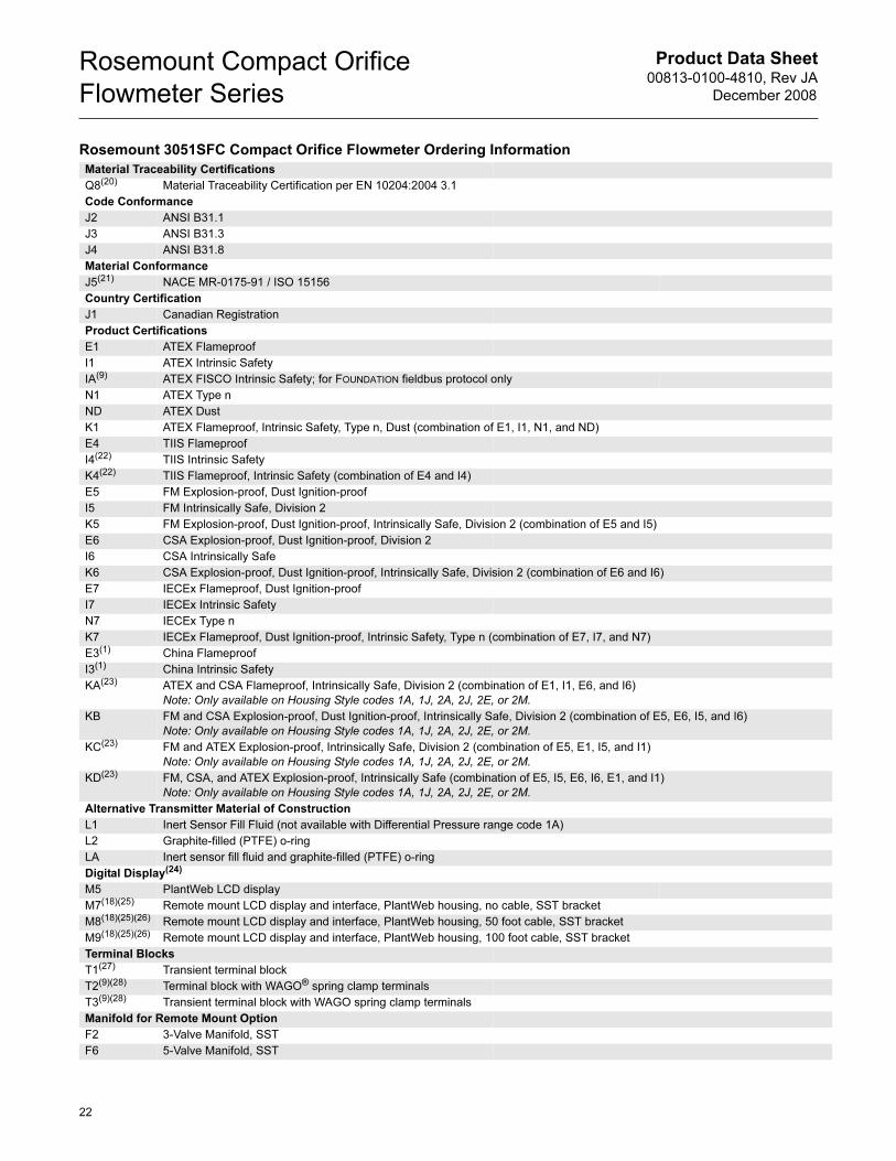
Material Traceability Certifications
Q8(20) Material Traceability Certification per EN 10204:2004 3.1
Code Conformance
J2 ANSI B31.1
J3 ANSI B31.3
J4 ANSI B31.8
Material Conformance
J5(21) NACE MR-0175-91 / ISO 15156
Country Certification
J1 Canadian Registration
Product Certifications
E1 ATEX Flameproof
I1 ATEX Intrinsic Safety
IA(9) ATEX FISCO Intrinsic Safety; for FOUNDATION fieldbus protocol only
N1 ATEX Type n
ND ATEX Dust
K1 ATEX Flameproof, Intrinsic Safety, Type n, Dust (combination of E1, I1, N1, and ND)
E4 TIIS Flameproof
I4(22) TIIS Intrinsic Safety
K4(22) TIIS Flameproof, Intrinsic Safety (combination of E4 and I4)
E5 FM Explosion-proof, Dust Ignition-proof
I5 FM Intrinsically Safe, Division 2
K5 FM Explosion-proof, Dust Ignition-proof, Intrinsically Safe, Division 2 (combination of E5 and I5)
E6 CSA Explosion-proof, Dust Ignition-proof, Division 2
I6 CSA Intrinsically Safe
K6 CSA Explosion-proof, Dust Ignition-proof, Intrinsically Safe, Division 2 (combination of E6 and I6)
E7 IECEx Flameproof, Dust Ignition-proof
I7 IECEx Intrinsic Safety
N7 IECEx Type n
K7 IECEx Flameproof, Dust Ignition-proof, Intrinsic Safety, Type n (combination of E7, I7, and N7)
E3(1) China Flameproof
I3(1) China Intrinsic Safety
KA(23) ATEX and CSA Flameproof, Intrinsically Safe, Division 2 (combination of E1, I1, E6, and I6)
Note: Only available on Housing Style codes 1A, 1J, 2A, 2J, 2E, or 2M.
KB FM and CSA Explosion-proof, Dust Ignition-proof, Intrinsically Safe, Division 2 (combination of E5, E6, I5, and I6)
Note: Only available on Housing Style codes 1A, 1J, 2A, 2J, 2E, or 2M.
KC(23) FM and ATEX Explosion-proof, Intrinsically Safe, Division 2 (combination of E5, E1, I5, and I1)
Note: Only available on Housing Style codes 1A, 1J, 2A, 2J, 2E, or 2M.
KD(23) FM, CSA, and ATEX Explosion-proof, Intrinsically Safe (combination of E5, I5, E6, I6, E1, and I1)
Note: Only available on Housing Style codes 1A, 1J, 2A, 2J, 2E, or 2M.
Alternative Transmitter Material of Construction
L1 Inert Sensor Fill Fluid (not available with Differential Pressure range code 1A)
L2 Graphite-filled (PTFE) o-ring
LA Inert sensor fill fluid and graphite-filled (PTFE) o-ring
Digital Display(24)
M5 PlantWeb LCD display
M7(18)(25) Remote mount LCD display and interface, PlantWeb housing, no cable, SST bracket
M8(18)(25)(26) Remote mount LCD display and interface, PlantWeb housing, 50 foot cable, SST bracket
M9(18)(25)(26) Remote mount LCD display and interface, PlantWeb housing, 100 foot cable, SST bracket
Terminal Blocks
T1(27) Transient terminal block
T2(9)(28) Terminal block with WAGO® spring clamp terminals
T3(9)(28) Transient terminal block with WAGO spring clamp terminals
Manifold for Remote Mount Option
F2 3-Valve Manifold, SST
F6 5-Valve Manifold, SST
Rosemount 3051SFC Compact Orifice Flowmeter Ordering Information
22
Product Data Sheet00813-0100-4810, Rev JA
December 2008
Rosemount Compact Orifice
Flowmeter Series
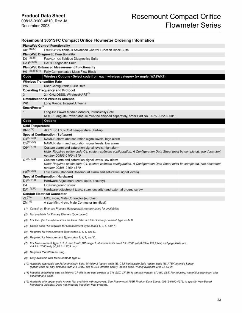
PlantWeb Control Functionality
A01(9)(29) FOUNDATION fieldbus Advanced Control Function Block Suite
PlantWeb Diagnostic Functionality
D01(9)(29) FOUNDATION fieldbus Diagnostics Suite
DA1(9)(30) HART Diagnostic Suite
PlantWeb Enhanced Measurement Functionality
H01(9)(29)(31) Fully Compensated Mass Flow Block
Code Wireless Options - Select code from each wireless category (example: WA2WK1)
Wireless Transmitter Rate
WA User Configurable Burst Rate
Operating Frequency and Protocol
3 2.4 GHz DSSS, WirelessHART™
Omnidirectional Wireless Antenna
WK Long Range, Integral Antenna
SmartPower™
1 Long-life Power Module Adapter, Intrinsically Safe
NOTE: Long-life Power Module must be shipped separately, order Part No. 00753-9220-0001.
Code Options
Cold Temperature
BRR(22) -60 °F (-51 °C) Cold Temperature Start-up
Special Configuration (Software)
C4(17)(32) NAMUR alarm and saturation signal levels, high alarm
C5(17)(32) NAMUR alarm and saturation signal levels, low alarm
C6(17)(32) Custom alarm and saturation signal levels, high alarm
Note: Requires option code C1, custom software configuration. A Configuration Data Sheet must be completed, see document
number 00806-0100-4810.
C7(17)(32) Custom alarm and saturation signal levels, low alarm
Note: Requires option code C1, custom software configuration. A Configuration Data Sheet must be completed, see document
number 00806-0100-4810.
C8(17)(32) Low alarm (standard Rosemount alarm and saturation signal levels)
Special Configuration (Hardware)
D1(17)(18) Hardware Adjustment (zero, span, security).
D4 External ground screw
DA(17)(18) Hardware adjustment (zero, span, security) and external ground screw
Conduit Electrical Connector
ZE(33) M12, 4-pin, Male Connector (eurofast)
ZM(33) A size Mini, 4-pin, Male Connector (minifast)
(1) Consult an Emerson Process Management representative for availability.
(2) Not available for Primary Element Type code C.
(3) For 2-in. (50.8 mm) line sizes the Beta Ratio is 0.6 for Primary Element Type code C.
(4) Option code R is required for Measurement Type codes 1, 3, 5, and 7.
(5) Required for Measurement Type codes 2, 4, 6, and D.
(6) Required for Measurement Type codes 3, 4, 7, and D.
(7) For Measurement Type 1, 2, 5, and 6 with DP range 1, absolute limits are 0.5 to 2000 psi (0,03 to 137,9 bar) and gage limits are -14.2 to 2000 psig (-0,98 to 137,9 bar).
(8) Requires PlantWeb housing.
(9) Only available with Measurement Type D.
(10) Available approvals are FM Intrinsically Safe, Division 2 (option code I5), CSA Intrinsically Safe (option code I6), ATEX Intrinsic Safety(option code I1; only available with 2.4 GHz), and IECEx Intrinsic Safety (option code I7; only available with 2.4 GHz).
(11) Material specified is cast as follows: CF-8M is the cast version of 316 SST, CF-3M is the cast version of 316L SST. For housing, material is aluminum with polyurethane paint.
(12) Available with output code A only. Not available with approvals. See Rosemount 753R Product Data Sheet, 00813-0100-4379, to specify Web-Based Monitoring Indicator. Does not integrate into plant host systems.
Rosemount 3051SFC Compact Orifice Flowmeter Ordering Information
23
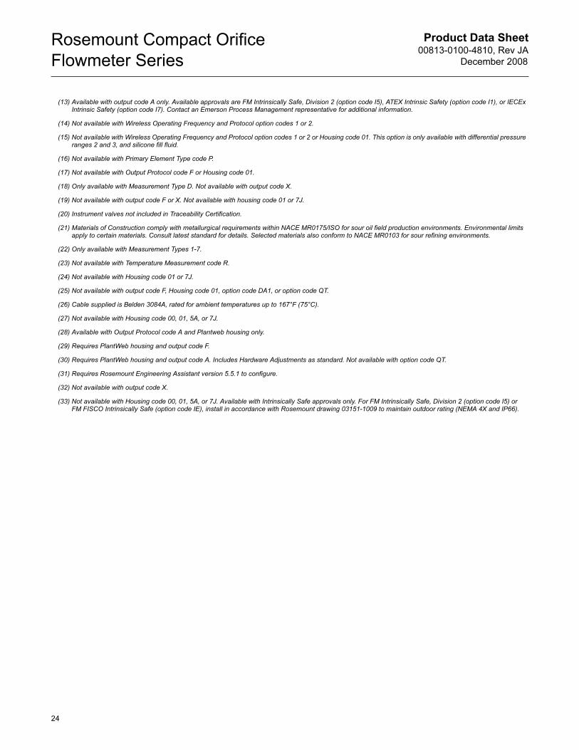
Product Data Sheet00813-0100-4810, Rev JA
December 2008
Rosemount Compact Orifice
Flowmeter Series
(13) Available with output code A only. Available approvals are FM Intrinsically Safe, Division 2 (option code I5), ATEX Intrinsic Safety (option code I1), or IECEx Intrinsic Safety (option code I7). Contact an Emerson Process Management representative for additional information.
(14) Not available with Wireless Operating Frequency and Protocol option codes 1 or 2.
(15) Not available with Wireless Operating Frequency and Protocol option codes 1 or 2 or Housing code 01. This option is only available with differential pressure ranges 2 and 3, and silicone fill fluid.
(16) Not available with Primary Element Type code P.
(17) Not available with Output Protocol code F or Housing code 01.
(18) Only available with Measurement Type D. Not available with output code X.
(19) Not available with output code F or X. Not available with housing code 01 or 7J.
(20) Instrument valves not included in Traceability Certification.
(21) Materials of Construction comply with metallurgical requirements within NACE MR0175/ISO for sour oil field production environments. Environmental limits apply to certain materials. Consult latest standard for details. Selected materials also conform to NACE MR0103 for sour refining environments.
(22) Only available with Measurement Types 1-7.
(23) Not available with Temperature Measurement code R.
(24) Not available with Housing code 01 or 7J.
(25) Not available with output code F, Housing code 01, option code DA1, or option code QT.
(26) Cable supplied is Belden 3084A, rated for ambient temperatures up to 167°F (75°C).
(27) Not available with Housing code 00, 01, 5A, or 7J.
(28) Available with Output Protocol code A and Plantweb housing only.
(29) Requires PlantWeb housing and output code F.
(30) Requires PlantWeb housing and output code A. Includes Hardware Adjustments as standard. Not available with option code QT.
(31) Requires Rosemount Engineering Assistant version 5.5.1 to configure.
(32) Not available with output code X.
(33) Not available with Housing code 00, 01, 5A, or 7J. Available with Intrinsically Safe approvals only. For FM Intrinsically Safe, Division 2 (option code I5) or FM FISCO Intrinsically Safe (option code IE), install in accordance with Rosemount drawing 03151-1009 to maintain outdoor rating (NEMA 4X and IP66).
24
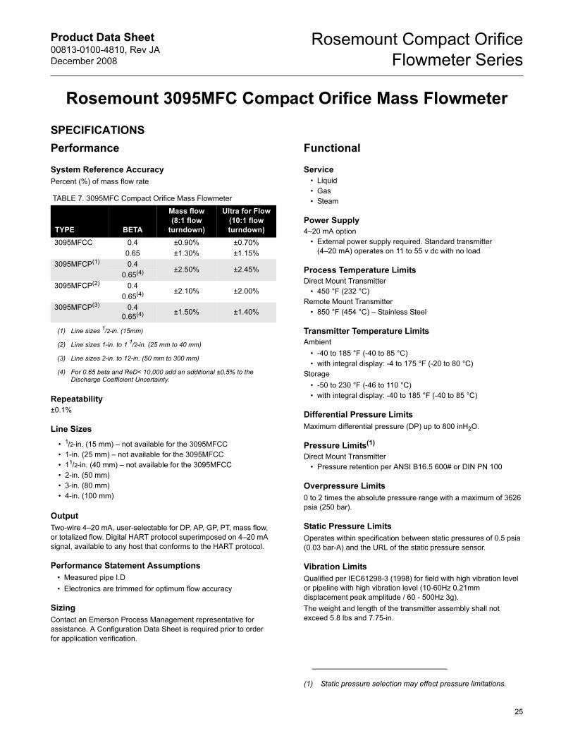
Product Data Sheet00813-0100-4810, Rev JA
December 2008
Rosemount Compact Orifice
Flowmeter Series
Rosemount 3095MFC Compact Orifice Mass Flowmeter
SPECIFICATIONS
Performance
System Reference Accuracy
Percent (%) of mass flow rate
Repeatability
±0.1%
Line Sizes
Output
Two-wire 4–20 mA, user-selectable for DP, AP, GP, PT, mass flow,
or totalized flow. Digital HART protocol superimposed on 4–20 mA
signal, available to any host that conforms to the HART protocol.
Performance Statement Assumptions
• Measured pipe I.D
• Electronics are trimmed for optimum flow accuracy
Sizing
Contact an Emerson Process Management representative for
assistance. A Configuration Data Sheet is required prior to order
for application verification.
Functional
Service
• Liquid
• Gas
• Steam
Power Supply
4–20 mA option
• External power supply required. Standard transmitter
(4–20 mA) operates on 11 to 55 v dc with no load
Process Temperature Limits
Direct Mount Transmitter
• 450 °F (232 °C)
Remote Mount Transmitter
• 850 °F (454 °C) – Stainless Steel
Transmitter Temperature Limits
Ambient
• -40 to 185 °F (-40 to 85 °C)
• with integral display: -4 to 175 °F (-20 to 80 °C)
Storage
• -50 to 230 °F (-46 to 110 °C)
• with integral display: -40 to 185 °F (-40 to 85 °C)
Differential Pressure Limits
Maximum differential pressure (DP) up to 800 inH2O.
Pressure Limits(1)
Direct Mount Transmitter
• Pressure retention per ANSI B16.5 600# or DIN PN 100
Overpressure Limits
0 to 2 times the absolute pressure range with a maximum of 3626
psia (250 bar).
Static Pressure Limits
Operates within specification between static pressures of 0.5 psia
(0.03 bar-A) and the URL of the static pressure sensor.
Vibration Limits
Qualified per IEC61298-3 (1998) for field with high vibration level
or pipeline with high vibration level (10-60Hz 0.21mm
displacement peak amplitude / 60 - 500Hz 3g).
The weight and length of the transmitter assembly shall not
exceed 5.8 lbs and 7.75-in.
TABLE 7. 3095MFC Compact Orifice Mass Flowmeter
TYPE BETA
Mass flow
(8:1 flow
turndown)
Ultra for Flow
(10:1 flow
turndown)
3095MFCC 0.4 ±0.90% ±0.70%
0.65 ±1.30% ±1.15%
3095MFCP(1)
(1) Line sizes 1/2-in. (15mm)
0.4±2.50% ±2.45%
0.65(4)
3095MFCP(2)
(2) Line sizes 1-in. to 1 1/2-in. (25 mm to 40 mm)
0.4±2.10% ±2.00%
0.65(4)
3095MFCP(3)
(3) Line sizes 2-in. to 12-in. (50 mm to 300 mm)
0.4
0.65(4)
(4) For 0.65 beta and ReD< 10,000 add an additional ±0.5% to the Discharge Coefficient Uncertainty.
±1.50% ±1.40%
• 1/2-in. (15 mm) – not available for the 3095MFCC
• 1-in. (25 mm) – not available for the 3095MFCC
• 11/2-in. (40 mm) – not available for the 3095MFCC
• 2-in. (50 mm)
• 3-in. (80 mm)
• 4-in. (100 mm)
(1) Static pressure selection may effect pressure limitations.
25
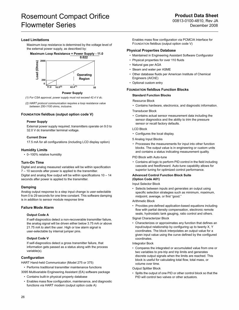
Product Data Sheet00813-0100-4810, Rev JA
December 2008
Rosemount Compact Orifice
Flowmeter Series
Load Limitations
Maximum loop resistance is determined by the voltage level of
the external power supply, as described by:
FOUNDATION fieldbus (output option code V)
Power Supply
External power supply required; transmitters operate on 9.0 to
32.0 V dc transmitter terminal voltage.
Current Draw
17.5 mA for all configurations (including LCD display option)
Humidity Limits
• 0–100% relative humidity
Turn-On Time
Digital and analog measured variables will be within specification
7 – 10 seconds after power is applied to the transmitter.
Digital and analog flow output will be within specifications 10 – 14
seconds after power is applied to the transmitter.
Damping
Analog output response to a step input change is user-selectable
from 0 to 29 seconds for one time constant. This software damping
is in addition to sensor module response time
Failure Mode Alarm
Output Code A
If self-diagnostics detect a non-recoverable transmitter failure,
the analog signal will be driven either below 3.75 mA or above
21.75 mA to alert the user. High or low alarm signal is
user-selectable by internal jumper pins.
Output Code V
If self-diagnostics detect a gross transmitter failure, that
information gets passed as a status along with the process
variable(s).
Configuration
HART Hand-held Communicator (Model 275 or 375)
• Performs traditional transmitter maintenance functions
3095 Multivariable Engineering Assistant (EA) software package
• Contains built-in physical property database
• Enables mass flow configuration, maintenance, and diagnostic
functions via HART modem (output option code A)
Enables mass flow configuration via PCMCIA Interface for
FOUNDATION fieldbus (output option code V)
Physical Properties Database
• Maintained in Engineering Assistant Software Configurator
• Physical properties for over 110 fluids
• Natural gas per AGA
• Steam and water per ASME
• Other database fluids per American Institute of Chemical
Engineers (AIChE)
• Optional custom entry
FOUNDATION fieldbus Function Blocks
Standard Function Blocks
Resource Block
• Contains hardware, electronics, and diagnostic information.
Transducer Block
• Contains actual sensor measurement data including the
sensor diagnostics and the ability to trim the pressure
sensor or recall factory defaults.
LCD Block
• Configures the local display.
5 Analog Input Blocks
• Processes the measurements for input into other function
blocks. The output value is in engineering or custom units
and contains a status indicating measurement quality.
PID Block with Auto-tune
• Contains all logic to perform PID control in the field including
cascade and feedforward. Auto-tune capability allows for
superior tuning for optimized control performance.
Advanced Control Function Block Suite
(Option Code A01)
Input Selector Block
• Selects between inputs and generates an output using
specific selection strategies such as minimum, maximum,
midpoint, average, or first “good.”
Arithmetic Block
• Provides pre-defined application-based equations including
flow with partial density compensation, electronic remote
seals, hydrostatic tank gauging, ratio control and others.
Signal Characterizer Block
• Characterizes or approximates any function that defines an
input/output relationship by configuring up to twenty X, Y
coordinates. The block interpolates an output value for a
given input value using the curve defined by the configured
coordinates.
Integrator Bock
• Compares the integrated or accumulated value from one or
two variables to pre-trip and trip limits and generates
discrete output signals when the limits are reached. This
block is useful for calculating total flow, total mass, or
volume over time.
Output Splitter Block
• Splits the output of one PID or other control block so that the
PID will control two valves or other actuators.
Lo
ad
(O
hm
s)
0
11.0 42.4(1)
55
Operating
Region
(1) For CSA approval, power supply must not exceed 42.4 V dc.
(2) HART protocol communication requires a loop resistance value between 250-1100 ohms, inclusive.
Power Supply
250
16.5(2)
Maximum Loop Resistance = Power Supply - 11.00.022
2000
26
Product Data Sheet00813-0100-4810, Rev JA
December 2008
Rosemount Compact Orifice
Flowmeter Series
27
Control Selector Block
• Selects one of up to three inputs (highest, middle, or lowest)
that are normally connected to the outputs of PID or other
control function blocks.
Physical
Temperature Measurement
Remote RTD
• 100 Ohm platinum with 1/2-in. NPT nipple and union (078
series with Rosemount 644 housing)
Model 0078D21N00A025T32Ex
Connection Head: 00644-4410-0011
• Standard RTD cable is shielded armored cable, length is 12
feet (3.66 m)
• Remote RTD material is SST
Thermowell
• 1/2-in. x 1/2-in. NPT, 316 SST
Electronic Connections for Remote Mount
• 1/2–14 NPT, G1/2, and M20 × 1.5 (CM20) conduit. HART
interface connections fixed to terminal block for output code A
Process-Wetted Parts
Integral Manifolds
• 316 SST
• Alloy C-276
Remote Manifolds
• 316 SST
• Alloy C-276
Transmitter Vent Valves and Process Flanges
• 316 SST
• Alloy C-276
• Glass-filled PTFE O-rings
Process Isolating Diaphragms
• 316L SST
• Alloy C-276
Integral Manifold O-Rings
• PTFE/Graphite
Non-Wetted Parts
Sensor Module Fill Fluid
• Silicone oil
• Inert Fill optional
Cover O-rings
• Buna-N
Remote Mounting Brackets
• SST
Electronic Housing
• Low copper aluminum, NEMA 4x, IP65
• SST (optional)
Paint
• Polyurethane
Bolts
• CS
Material of Construction
Body/Plate
• 316 SST
• 50 micro-inch Ra surface finish
Manifold Head/Valves
• 316 SST
Flange Studs and Nuts
• Customer supplied
• Available as a spare part
Transmitter Connection Studs and Nuts
• Studs– A193 Grade B8M.
• Nuts– A194 Grade 8M.
Gasket and O-rings
• Gaskets are customer supplied.
• Durlon 8500 fiber gaskets are recommended. Consult an
Emerson Process Management representative for use with
other gaskets.
• Available as a spare part
NOTE
Gaskets and O-rings should be replaced when the 405 is
disassembled.
Transmitter Connections
Remote Mount
• Available with 1/4-in. (standard) or 1/2-in. (option code E)
connections
Orifice Type
• Square edged, Wafer style
Orifice Pressure Taps
• Corner
Process Connections
Mounts between the following flange configurations
ANSI alignment ring is included as standard when ordering
ASME B16.5
(ANSI) DIN JIS
Class 150
Class 300
Class 600
PN16 (option code G)
PN40 (option code H)
PN100 (option code H)
10k (option code B)
20k (option code R)
40k (option code S)
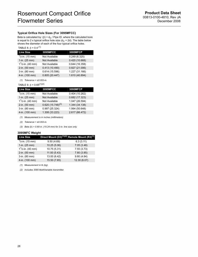
Product Data Sheet00813-0100-4810, Rev JA
December 2008
Rosemount Compact Orifice
Flowmeter Series
Typical Orifice Hole Sizes (For 3095MFCC)
Beta is calculated by: (β) = dC / Pipe ID, where the calculated bore
is equal to 2 x typical orifice hole size (dC = 2d). The table below
shows the diameter of each of the four typical orifice holes.
3095MFC Weight
TABLE 8. β = 0.4 (1)
(1) Tolerance = ±0.002-in.
Line Size 3095MFCC 3095MFCP
1/2-in. (15 mm) Not Available 0.249 (6.325)
1-in. (25 mm) Not Available 0.420 (10.668)
11/2-in. (40 mm) Not Available 0.644 (16.358)
2-in. (50 mm) 0.413 (10.490) 0.827 (21.006)
3-in. (80 mm) 0.614 (15.596) 1.227 (31.166)
4-in. (100 mm) 0.805 (20.447) 1.610 (40.894)
TABLE 9. β = 0.65(1)(2)
(1) Measurement is in inches (millimeters)
(2) Tolerance = ±0.002-in.
Line Size 3095MFCC 3095MFCP
1/2-in. (15 mm) Not Available 0.404 (10.262)
1-in. (25 mm) Not Available 0.682 (17.323)
11/2-in. (40 mm) Not Available 1.047 (26.594)
2-in. (50 mm) 0.620 (15.748)(3)
(3) Beta (β) = 0.60-in. (15.24 mm) for 2-in. line size only.
1.344 (34.138)
3-in. (80 mm) 0.997 (25.324) 1.994 (50.648)
4-in. (100 mm) 1.308 (33.223) 2.617 (66.472)
Line Size Direct Mount (D3)(1)(2)
(1) Measurement in lb (kg).
(2) Includes 3095 MultiVariable transmitter.
Remote Mount (R3)(1)
1/2-in. (15 mm) 9.50 (4.69) 6.3 (3.11)
1-in. (25 mm) 10.25 (5.06) 7.05 (3.48)
11/2-in. (40 mm) 10.75 (5.31) 7.55 (3.73)
2-in. (50 mm) 11.00 (5.43) 7.80 (3.85)
3-in. (80 mm) 13.00 (6.42) 9.80 (4.84)
4-in. (100 mm) 15.50 (7.65) 12.30 (6.07)
28
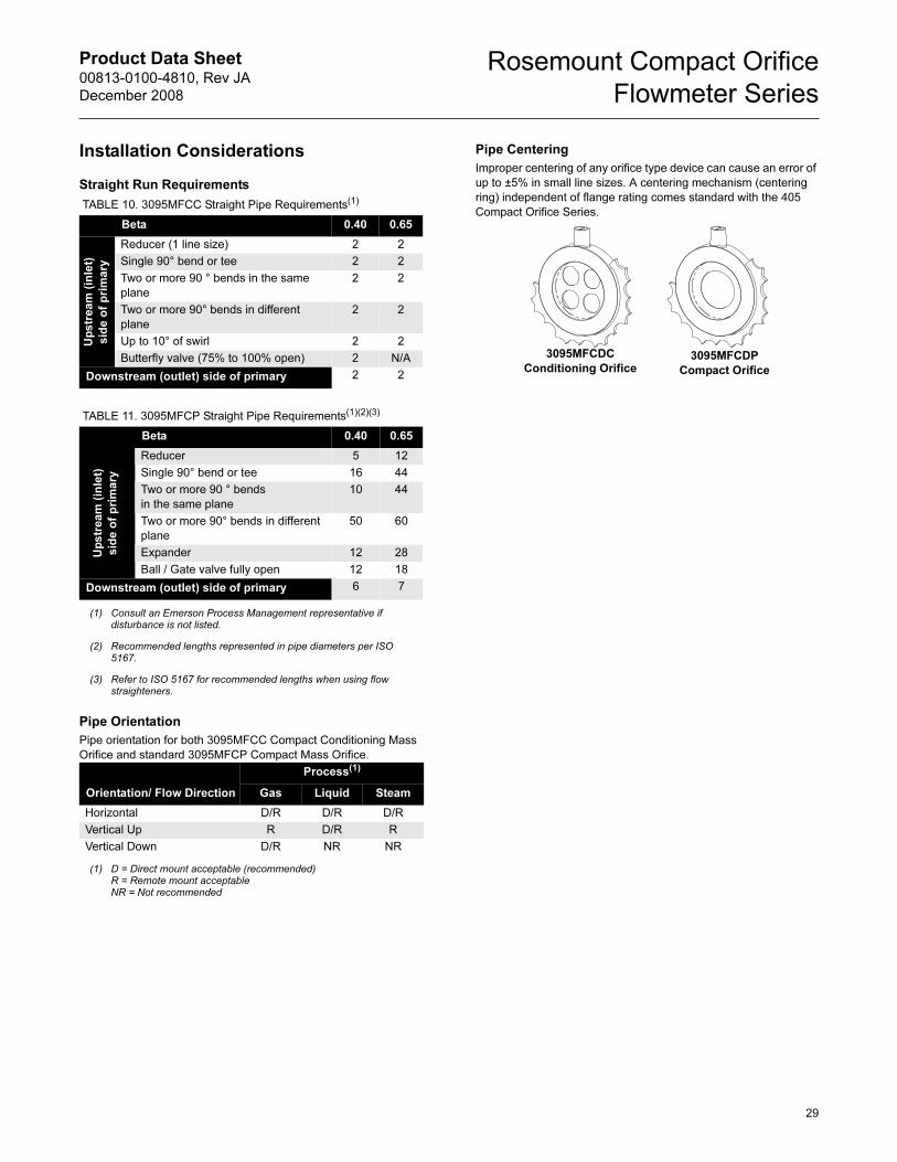
Product Data Sheet00813-0100-4810, Rev JA
December 2008
Rosemount Compact Orifice
Flowmeter Series
29
Installation Considerations
Straight Run Requirements
Pipe Orientation
Pipe orientation for both 3095MFCC Compact Conditioning Mass
Orifice and standard 3095MFCP Compact Mass Orifice.
Pipe Centering
Improper centering of any orifice type device can cause an error of
up to ±5% in small line sizes. A centering mechanism (centering
ring) independent of flange rating comes standard with the 405
Compact Orifice Series. TABLE 10. 3095MFCC Straight Pipe Requirements(1)
Beta 0.40 0.65
Up
str
ea
m (
inle
t)
sid
e o
f p
rim
ary
Reducer (1 line size) 2 2
Single 90° bend or tee 2 2
Two or more 90 ° bends in the same
plane
2 2
Two or more 90° bends in different
plane
2 2
Up to 10° of swirl 2 2
Butterfly valve (75% to 100% open) 2 N/A
Downstream (outlet) side of primary 2 2
TABLE 11. 3095MFCP Straight Pipe Requirements(1)(2)(3)
(1) Consult an Emerson Process Management representative if disturbance is not listed.
Beta 0.40 0.65
(2)(3)
(2) Recommended lengths represented in pipe diameters per ISO 5167.
(3) Refer to ISO 5167 for recommended lengths when using flow straighteners.
Reducer 5 12
Single 90° bend or tee 16 44
Two or more 90 ° bends
in the same plane
10 44
Two or more 90° bends in different
plane
50 60
Expander 12 28
Ball / Gate valve fully open 12 18
Downstream (outlet) side of primary 6 7
Orientation/ Flow Direction
Process(1)
(1) D = Direct mount acceptable (recommended)R = Remote mount acceptableNR = Not recommended
Gas Liquid Steam
Horizontal D/R D/R D/R
Vertical Up R D/R R
Vertical Down D/R NR NR
Up
str
ea
m (
inle
t)
sid
e o
f p
rim
ary
3095MFCDP
Compact Orifice
3095MFCDC
Conditioning Orifice
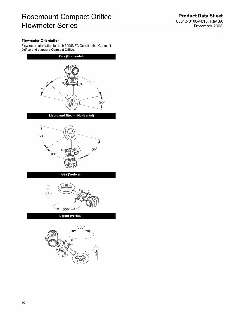
Product Data Sheet00813-0100-4810, Rev JA
December 2008
Rosemount Compact Orifice
Flowmeter Series
Flowmeter Orientation
Flowmeter orientation for both 3095MFC Conditioning Compact
Orifice and standard Compact Orifice.
Gas (Horizontal)
Liquid and Steam (Horizontal)
Gas (Vertical)
Liquid (Vertical)
30°
120°
30°
50°
80°50°
360°
FLO
W
360°
FLO
W
30
Product Data Sheet00813-0100-4810, Rev JA
December 2008
Rosemount Compact Orifice
Flowmeter Series
PRODUCT CERTIFICATIONS
Rosemount 3095 with HART
European Directive InformationThe EC declaration of conformity for all applicable European
directives for this product can be found on the Rosemount website
at www.rosemount.com. A hard copy may be obtained by
contacting our local sales office.
ATEX Directive (94/9/EC)Emerson Process Management complies with the ATEX Directive.
European Pressure Equipment Directive (PED)
(97/23/EC)3095M_2/3,4/D Flow Transmitters — QS Certificate of Assessment - EC No. PED-H-20Module H Conformity Assessment
All other 3095_ Transmitters/Level Controller — Sound Engineering Practice
Transmitter Attachments: Process Flange - Manifold —
Sound Engineering Practice
Electro Magnetic Compatibility (EMC)
(89/336/EEC)3095MV Flow Transmitters
— EN 50081-1: 1992; EN 50082-2:1995; EN 61326-1:1997 – Industrial
Ordinary Location Certification for Factory
MutualAs standard, the transmitter has been examined and tested to
determine that the design meets basic electrical, mechanical, and
fire protection requirements by FM, a nationally recognized testing
laboratory (NRTL) as accredited by the Federal Occupational
Safety and Health Administration (OSHA).
Hazardous Locations Certifications
North American CertificationsFM Approvals
E5 Explosion Proof for Class I, Division 1, Groups B, C, and D.
Dust-Ignition Proof for Class II/Class III, Division 1, Groups
E, F, and G. Enclosure type NEMA 4X. Factory Sealed.
Provides nonincendive RTD connections for Class I, Division
2, Groups A, B, C, and D.
I5 Intrinsically Safe for use in Class I, II and III, Division 1,
Groups A, B, C, D, E, F, and G hazardous outdoor locations.
Non-incendive for Class I, Division 2, Groups A, B, C, and D.
Temperature Code T4. Factory Sealed.
For input parameters and installation see control drawing
03095-1020.
Canadian Standards Association (CSA)
E6 Explosion Proof for Class I, Division 1, Groups B, C, and D.
Dust-Ignition Proof for Class II/Class III, Division 1, Groups
E, F, and G. CSA enclosure Type 4X suitable for indoor and
outdoor hazardous locations. Provides nonincendive RTD
connection for Class I, Division 2, Groups A, B, C, and
D.Factory Sealed. Install in accordance with Rosemount
Drawing 03095-1024. Approved for Class I, Division 2,
Groups A, B, C, and D.
I6 Intrinsically Safe for Class I, Division 1, Groups A, B, C, and
D. when installed in accordance with Rosemount drawing
03095-1021. Temperature Code T3C.
For input parameters and installation see control drawing
03095-1021.
European CertificationsI1 ATEX Intrinsic Safety
Certificate Number: BAS98ATEX1359X II 1 G
EEx ia IIC T5 (Tamb = –45 °C to 40 °C)
EEx ia IIC T4 (Tamb = –45 °C to 70 °C)
1180
Special Conditions for Safe Use
The 3095, when fitted with the transient terminal block
(order code B), are not capable of withstanding the 500 volts
insulation test required by EN50 020, Clause 6.4.12 (1994).
This condition must be accounted for during installation.
N1 ATEX Type N
Certificate Number: BAS98ATEX3360X II 3 G
EEx nL IIC T5 (Tamb = –45 °C to 40 °C)
EEx nL IIC T4 (Tamb = –45 °C to 70 °C)
Ui = 55V
The apparatus is designed for connection to a remote
temperature sensor such as a resistance temperature
detection (RTD)
TABLE 12. Connection Parameters (Power/Signal
Terminals)
Ui = 30V
Ii = 200 mA
Pi = 1.0 W
Ci = 0.012 µF
Li = 0
TABLE 13. Temperature Sensor Connection Parameters
Uo = 30V
Io = 19 mA
Po = 140 mW
Ci = 0.002 µF
Li = 0
TABLE 14. Temp Sensor Terminals Connection Parameters
Co = 0.066 �F Gas Group IIC
Co = 0.560 �F Gas Group IIB
Co = 1.82 �F Gas Group IIA
Lo = 96 mH Gas Group IIC
Lo = 365 mH Gas Group IIB
Lo = 696 mH Gas Group IIA
Lo/Ro = 247 �H/ohm Gas Group IIC
Lo/Ro = 633 �H/ohm Gas Group IIB
Lo/Ro= 633 �H/ohm Gas Group IIA
31
Product Data Sheet00813-0100-4810, Rev JA
December 2008
Rosemount Compact Orifice
Flowmeter Series
Special Conditions for Safe Use
The 3095, when fitted with the transient terminal block
(order code B), are not capable of withstanding the 500 volts
insulation test required by EN50 021, Clause 9.1 (1995).
This condition must be accounted for during installation.
E1 ATEX Flameproof
Certificate Number: KEMA02ATEX2320X II 1/2 G
EEx d IIC T5 (-50°C ≤ Tamb ≤ 80°C)
T6 (-50°C ≤ Tamb ≤ 65°C)
1180
Special Conditions for Safe Use (x):
The device contains a thin wall diaphragm. Installation,
maintenance, and use shall take into account the
environmental conditions to which the diaphragm will be
subjected. The manufacturer’s instructions for installation
and maintenance shall be followed in detail to assure safety
during its expected lifetime.
ND ATEX Dust
Certificate Number: KEMA02ATEX2321 II 1 D
V = 55 Vdc MAX
I = 23 mA MAX
IP66
1180
Combinations of CertificationsStainless steel certification tag is provided when optional approval
is specified. Once a device labeled with multiple approval types is
installed, it should not be reinstalled using any other approval
types. Permanently mark the approval label to distinguish it from
unused approval types.
K5 E5 and I5 combination
K6 E6 and I6 combination
K1 I1, N1, E1, and ND combination
Rosemount 3095 with Fieldbus
European Directive Information
The EC declaration of conformity for all applicable European
directives for this product can be found on the Rosemount website
at www.rosemount.com. A hard copy may be obtained by
contacting our local sales office.
ATEX Directive (94/9/EC)
Emerson Process Management complies with the ATEX Directive.
European Pressure Equipment Directive (PED)
(97/23/EC)
3095F_2/3,4/D and 3095M_2/3,4/D Flow Transmitters
— QS Certificate of Assessment - EC No. PED-H-20
Module H Conformity Assessment
All other 3095_ Transmitters/Level Controller
— Sound Engineering Practice
Transmitter Attachments: Process Flange - Manifold
— Sound Engineering Practice
Primary Elements, Flowmeter
— See appropriate Primary Element QIG
Electro Magnetic Compatibility (EMC) (89/336/EEC)
3095 Flow Transmitters
— EN 50081-1: 1992; EN 50082-2:1995; EN 61326-1:1997 –
Industrial
Ordinary Location Certification for Factory Mutual
As standard, the transmitter has been examined and tested to
determine that the design meets basic electrical, mechanical, and
fire protection requirements by FM, a nationally recognized testing
laboratory (NRTL) as accredited by the Federal Occupational
Safety and Health Administration (OSHA).
Rosemount 3095 Fieldbus Hazardous Locations Certifications
North American Certifications
FM Approvals
E5 Explosion Proof for Class I, Division 1, Groups B, C, and D.
Dust-Ignition Proof for Class II/Class III, Division 1, Groups
E, F, and G. Enclosure type NEMA 4X. Factory Sealed.
Provides nonincendive RTD connections for Class I,
Division 2, Groups A, B, C, and D.
I5 Intrinsically Safe for use in Class I, II and III, Division 1,
Groups A, B, C, D, E, F, and G hazardous outdoor locations.
Non-incendive for Class I, Division 2, Groups A, B, C, and D.
Temperature Code T4. Factory Sealed.
For input parameters and installation see control drawing
03095-1020.
IE FISCO for use in Class I, II and III, Division 1, Groups A, B,
C, D, E, F, and G hazardous outdoor locations. Temperature
Code T4. Factory Sealed.
For input parameters and installation see control drawing
03095-1020.
Combinations of Certifications
Stainless steel certification tag is provided when optional approval
is specified. Once a device labeled with multiple approval types is
installed, it should not be reinstalled using any other approval
types. Permanently mark the approval label to distinguish it from
unused approval types.
K5 E5 and I5 combination
Canadian Standards Association (CSA)
IF CSA FISCO Intrinsically Safe; for FOUNDATION fieldbus
protocol only
European Certifications
IA ATEX FISCO Intrinsically Safe; for FOUNDATION fieldbus
protocol only
Australian Certifications
IG IECEx FISCO Intrinsic Safety
32
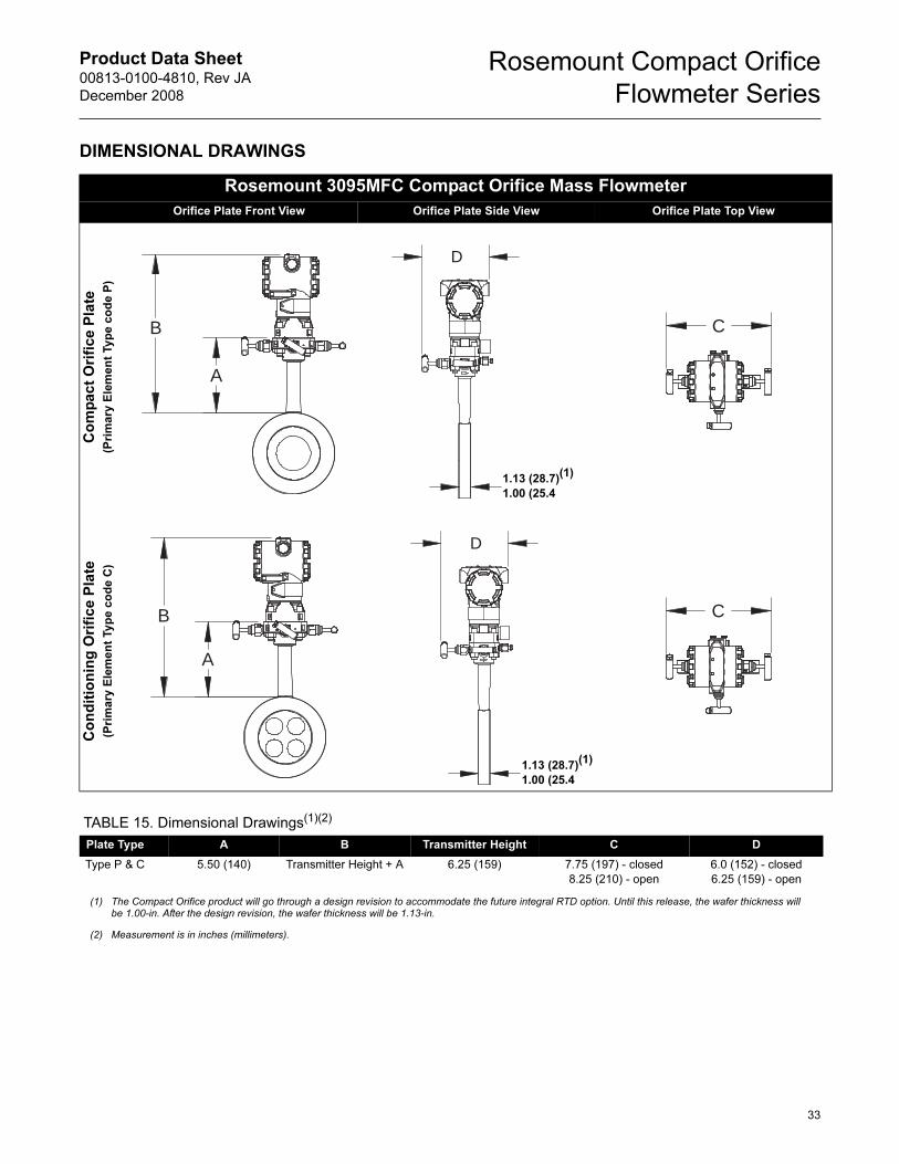
Product Data Sheet00813-0100-4810, Rev JA
December 2008
Rosemount Compact Orifice
Flowmeter Series
DIMENSIONAL DRAWINGS
Rosemount 3095MFC Compact Orifice Mass Flowmeter
Orifice Plate Front View Orifice Plate Side View Orifice Plate Top View
Co
mp
act
Ori
fice P
late
(Pri
ma
ry E
lem
en
t Ty
pe
co
de
P)
Co
nd
itio
nin
g O
rifi
ce P
late
(Pri
ma
ry E
lem
en
t Ty
pe
co
de
C)
A
B
D
1.13 (28.7)(1)
1.00 (25.4
C
A
B
D
1.13 (28.7)(1)
1.00 (25.4
C
TABLE 15. Dimensional Drawings(1)(2)
Plate Type(1)(2) A B Transmitter Height C D
Type P & C 5.50 (140) Transmitter Height + A 6.25 (159) 7.75 (197) - closed
8.25 (210) - open
6.0 (152) - closed
6.25 (159) - open
(1) The Compact Orifice product will go through a design revision to accommodate the future integral RTD option. Until this release, the wafer thickness will be 1.00-in. After the design revision, the wafer thickness will be 1.13-in.
(2) Measurement is in inches (millimeters).
33
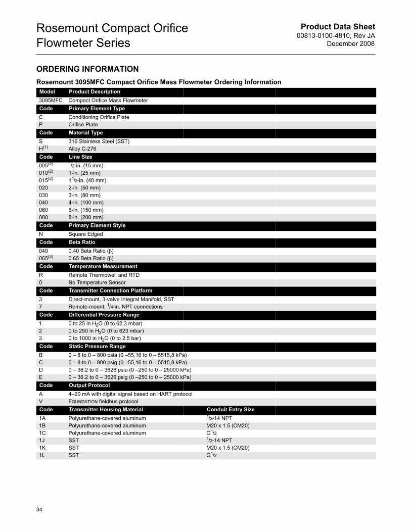
Product Data Sheet00813-0100-4810, Rev JA
December 2008
Rosemount Compact Orifice
Flowmeter Series
ORDERING INFORMATION
Rosemount 3095MFC Compact Orifice Mass Flowmeter Ordering Information
Model Product Description
3095MFC Compact Orifice Mass Flowmeter
Code Primary Element Type
C Conditioning Orifice Plate
P Orifice Plate
Code Material Type
S 316 Stainless Steel (SST)
H(1) Alloy C-276
Code Line Size
005(2) 1/2-in. (15 mm)
010(2) 1-in. (25 mm)
015(2) 11/2-in. (40 mm)
020 2-in. (50 mm)
030 3-in. (80 mm)
040 4-in. (100 mm)
060 6-in. (150 mm)
080 8-in. (200 mm)
Code Primary Element Style
N Square Edged
Code Beta Ratio
040 0.40 Beta Ratio (β)
065(3) 0.65 Beta Ratio (β)
Code Temperature Measurement
R Remote Thermowell and RTD
0 No Temperature Sensor
Code Transmitter Connection Platform
3 Direct-mount, 3-valve Integral Manifold, SST
7 Remote-mount, 1/4-in. NPT connections
Code Differential Pressure Range
1 0 to 25 in H2O (0 to 62,3 mbar)
2 0 to 250 in H2O (0 to 623 mbar)
3 0 to 1000 in H2O (0 to 2,5 bar)
Code Static Pressure Range
B 0 – 8 to 0 – 800 psia (0 –55,16 to 0 – 5515,8 kPa)
C 0 – 8 to 0 – 800 psig (0 –55,16 to 0 – 5515,8 kPa)
D 0 – 36.2 to 0 – 3626 psia (0 –250 to 0 – 25000 kPa)
E 0 – 36.2 to 0 – 3626 psig (0 –250 to 0 – 25000 kPa)
Code Output Protocol
A 4–20 mA with digital signal based on HART protocol
V FOUNDATION fieldbus protocol
Code Transmitter Housing Material Conduit Entry Size
1A Polyurethane-covered aluminum 1/2-14 NPT
1B Polyurethane-covered aluminum M20 x 1.5 (CM20)
1C Polyurethane-covered aluminum G1/2
1J SST 1/2-14 NPT
1K SST M20 x 1.5 (CM20)
1L SST G1/2
34
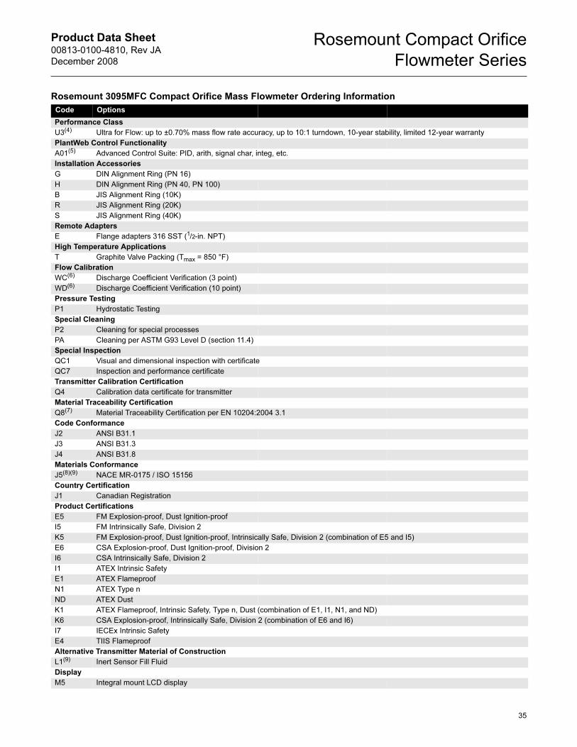
Product Data Sheet00813-0100-4810, Rev JA
December 2008
Rosemount Compact Orifice
Flowmeter Series
Code Options
Performance Class
U3(4) Ultra for Flow: up to ±0.70% mass flow rate accuracy, up to 10:1 turndown, 10-year stability, limited 12-year warranty
PlantWeb Control Functionality
A01(5) Advanced Control Suite: PID, arith, signal char, integ, etc.
Installation Accessories
G DIN Alignment Ring (PN 16)
H DIN Alignment Ring (PN 40, PN 100)
B JIS Alignment Ring (10K)
R JIS Alignment Ring (20K)
S JIS Alignment Ring (40K)
Remote Adapters
E Flange adapters 316 SST (1/2-in. NPT)
High Temperature Applications
T Graphite Valve Packing (Tmax = 850 °F)
Flow Calibration
WC(6) Discharge Coefficient Verification (3 point)
WD(6) Discharge Coefficient Verification (10 point)
Pressure Testing
P1 Hydrostatic Testing
Special Cleaning
P2 Cleaning for special processes
PA Cleaning per ASTM G93 Level D (section 11.4)
Special Inspection
QC1 Visual and dimensional inspection with certificate
QC7 Inspection and performance certificate
Transmitter Calibration Certification
Q4 Calibration data certificate for transmitter
Material Traceability Certification
Q8(7) Material Traceability Certification per EN 10204:2004 3.1
Code Conformance
J2 ANSI B31.1
J3 ANSI B31.3
J4 ANSI B31.8
Materials Conformance
J5(8)(9) NACE MR-0175 / ISO 15156
Country Certification
J1 Canadian Registration
Product Certifications
E5 FM Explosion-proof, Dust Ignition-proof
I5 FM Intrinsically Safe, Division 2
K5 FM Explosion-proof, Dust Ignition-proof, Intrinsically Safe, Division 2 (combination of E5 and I5)
E6 CSA Explosion-proof, Dust Ignition-proof, Division 2
I6 CSA Intrinsically Safe, Division 2
I1 ATEX Intrinsic Safety
E1 ATEX Flameproof
N1 ATEX Type n
ND ATEX Dust
K1 ATEX Flameproof, Intrinsic Safety, Type n, Dust (combination of E1, I1, N1, and ND)
K6 CSA Explosion-proof, Intrinsically Safe, Division 2 (combination of E6 and I6)
I7 IECEx Intrinsic Safety
E4 TIIS Flameproof
Alternative Transmitter Material of Construction
L1(9) Inert Sensor Fill Fluid
Display
M5 Integral mount LCD display
Rosemount 3095MFC Compact Orifice Mass Flowmeter Ordering Information
35
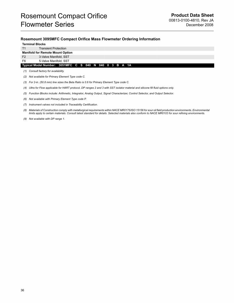
Product Data Sheet00813-0100-4810, Rev JA
December 2008
Rosemount Compact Orifice
Flowmeter Series
Terminal Blocks
T1 Transient Protection
Manifold for Remote Mount Option
F2 3-Valve Manifold, SST
F6 5-Valve Manifold, SST
Typical Model Number: 3051MFC C S 040 N 040 0 3 B A 1A
(1) Consult factory for availability.
(2) Not available for Primary Element Type code C.
(3) For 2-in. (50.8 mm) line sizes the Beta Ratio is 0.6 for Primary Element Type code C.
(4) Ultra for Flow applicable for HART protocol, DP ranges 2 and 3 with SST isolator material and silicone fill fluid options only.
(5) Function Blocks include: Arithmetic, Integrator, Analog Output, Signal Characterizer, Control Selector, and Output Selector.
(6) Not available with Primary Element Type code P.
(7) Instrument valves not included in Traceability Certification.
(8) Materials of Construction comply with metallurgical requirements within NACE MR0175/ISO 15156 for sour oil field production environments. Environmental limits apply to certain materials. Consult latest standard for details. Selected materials also conform to NACE MR0103 for sour refining environments.
(9) Not available with DP range 1.
Rosemount 3095MFC Compact Orifice Mass Flowmeter Ordering Information
36
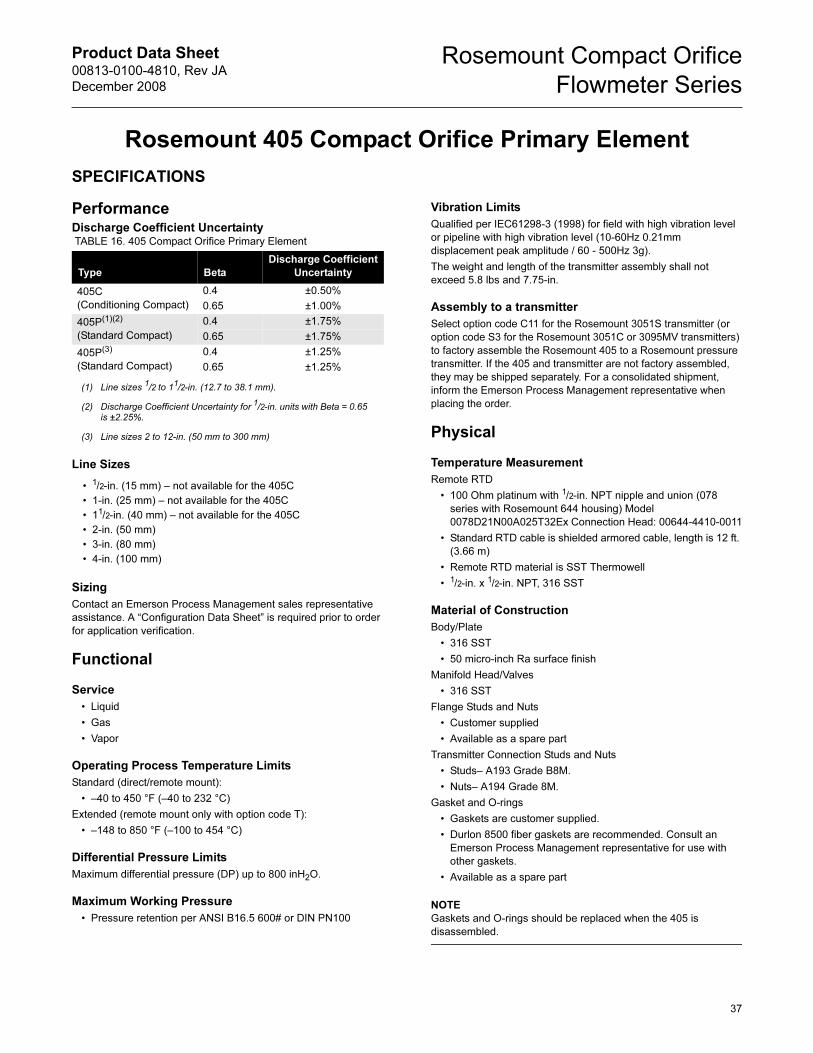
Product Data Sheet00813-0100-4810, Rev JA
December 2008
Rosemount Compact Orifice
Flowmeter Series
Rosemount 405 Compact Orifice Primary Element
SPECIFICATIONS
PerformanceDischarge Coefficient Uncertainty
Line Sizes
Sizing
Contact an Emerson Process Management sales representative
assistance. A “Configuration Data Sheet” is required prior to order
for application verification.
Functional
Service
• Liquid
• Gas
• Vapor
Operating Process Temperature Limits
Standard (direct/remote mount):
• –40 to 450 °F (–40 to 232 °C)
Extended (remote mount only with option code T):
• –148 to 850 °F (–100 to 454 °C)
Differential Pressure Limits
Maximum differential pressure (DP) up to 800 inH2O.
Maximum Working Pressure
• Pressure retention per ANSI B16.5 600# or DIN PN100
Vibration Limits
Qualified per IEC61298-3 (1998) for field with high vibration level
or pipeline with high vibration level (10-60Hz 0.21mm
displacement peak amplitude / 60 - 500Hz 3g).
The weight and length of the transmitter assembly shall not
exceed 5.8 lbs and 7.75-in.
Assembly to a transmitter
Select option code C11 for the Rosemount 3051S transmitter (or
option code S3 for the Rosemount 3051C or 3095MV transmitters)
to factory assemble the Rosemount 405 to a Rosemount pressure
transmitter. If the 405 and transmitter are not factory assembled,
they may be shipped separately. For a consolidated shipment,
inform the Emerson Process Management representative when
placing the order.
Physical
Temperature Measurement
Remote RTD
• 100 Ohm platinum with 1/2-in. NPT nipple and union (078
series with Rosemount 644 housing) Model
0078D21N00A025T32Ex Connection Head: 00644-4410-0011
• Standard RTD cable is shielded armored cable, length is 12 ft.
(3.66 m)
• Remote RTD material is SST Thermowell
• 1/2-in. x 1/2-in. NPT, 316 SST
Material of Construction
Body/Plate
• 316 SST
• 50 micro-inch Ra surface finish
Manifold Head/Valves
• 316 SST
Flange Studs and Nuts
• Customer supplied
• Available as a spare part
Transmitter Connection Studs and Nuts
• Studs– A193 Grade B8M.
• Nuts– A194 Grade 8M.
Gasket and O-rings
• Gaskets are customer supplied.
• Durlon 8500 fiber gaskets are recommended. Consult an
Emerson Process Management representative for use with
other gaskets.
• Available as a spare part
NOTE
Gaskets and O-rings should be replaced when the 405 is
disassembled.
TABLE 16. 405 Compact Orifice Primary Element
Type Beta
Discharge Coefficient
Uncertainty
405C
(Conditioning Compact)
0.4 ±0.50%
0.65 ±1.00%
405P(1)(2)
(Standard Compact)
(1) Line sizes 1/2 to 11/2-in. (12.7 to 38.1 mm).
(2) Discharge Coefficient Uncertainty for 1/2-in. units with Beta = 0.65 is ±2.25%.
0.4 ±1.75%
0.65 ±1.75%
405P(3)
(Standard Compact)
(3) Line sizes 2 to 12-in. (50 mm to 300 mm)
0.4 ±1.25%
0.65 ±1.25%
• 1/2-in. (15 mm) – not available for the 405C
• 1-in. (25 mm) – not available for the 405C
• 11/2-in. (40 mm) – not available for the 405C
• 2-in. (50 mm)
• 3-in. (80 mm)
• 4-in. (100 mm)
37
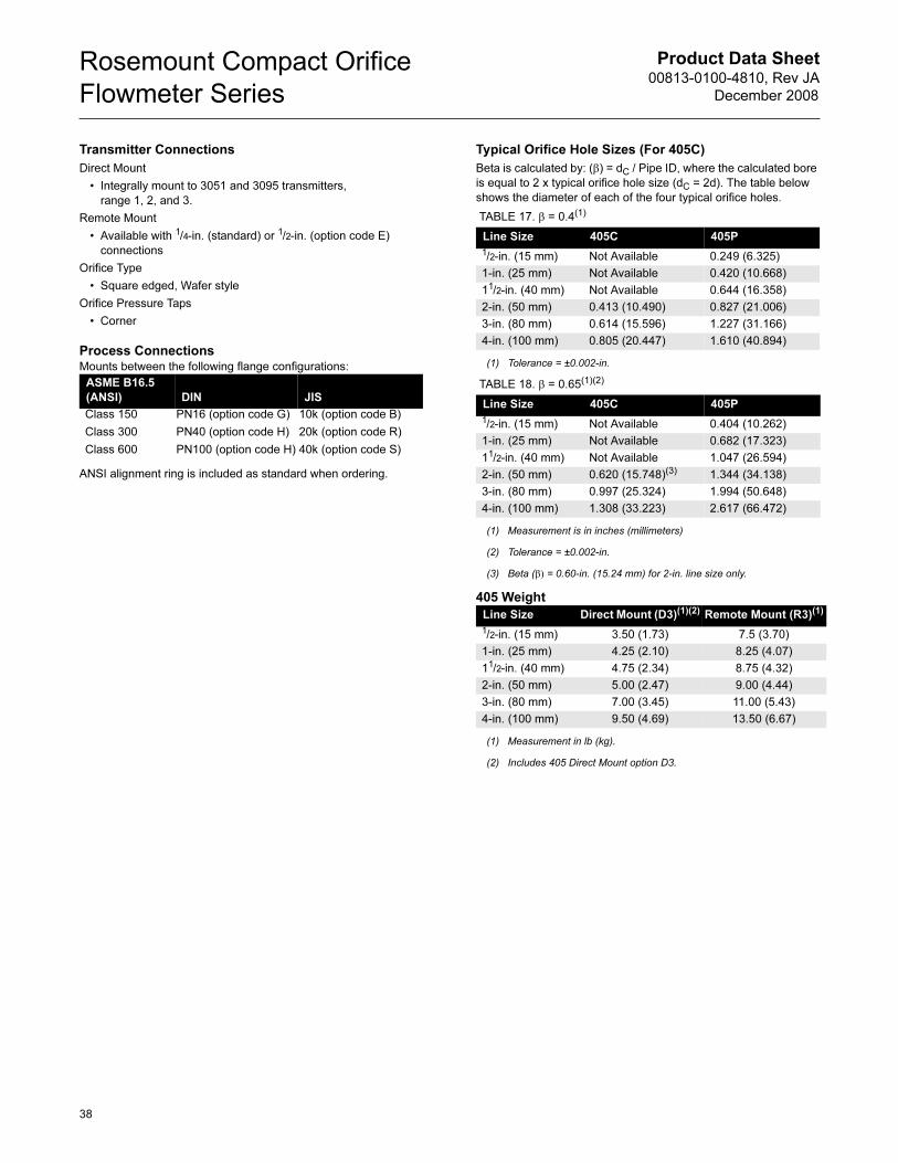
Product Data Sheet00813-0100-4810, Rev JA
December 2008
Rosemount Compact Orifice
Flowmeter Series
38
Transmitter Connections
Direct Mount
• Integrally mount to 3051 and 3095 transmitters,
range 1, 2, and 3.
Remote Mount
• Available with 1/4-in. (standard) or 1/2-in. (option code E)
connections
Orifice Type
• Square edged, Wafer style
Orifice Pressure Taps
• Corner
Process ConnectionsMounts between the following flange configurations:
ANSI alignment ring is included as standard when ordering.
Typical Orifice Hole Sizes (For 405C)
Beta is calculated by: (β) = dC / Pipe ID, where the calculated bore
is equal to 2 x typical orifice hole size (dC = 2d). The table below
shows the diameter of each of the four typical orifice holes.
405 Weight
ASME B16.5
(ANSI) DIN JIS
Class 150
Class 300
Class 600
PN16 (option code G)
PN40 (option code H)
PN100 (option code H)
10k (option code B)
20k (option code R)
40k (option code S)
TABLE 17. β = 0.4(1)
(1) Tolerance = ±0.002-in.
Line Size 405C 405P
1/2-in. (15 mm) Not Available 0.249 (6.325)
1-in. (25 mm) Not Available 0.420 (10.668)
11/2-in. (40 mm) Not Available 0.644 (16.358)
2-in. (50 mm) 0.413 (10.490) 0.827 (21.006)
3-in. (80 mm) 0.614 (15.596) 1.227 (31.166)
4-in. (100 mm) 0.805 (20.447) 1.610 (40.894)
TABLE 18. β = 0.65(1)(2)
(1) Measurement is in inches (millimeters)
(2) Tolerance = ±0.002-in.
Line Size 405C 405P
1/2-in. (15 mm) Not Available 0.404 (10.262)
1-in. (25 mm) Not Available 0.682 (17.323)
11/2-in. (40 mm) Not Available 1.047 (26.594)
2-in. (50 mm) 0.620 (15.748)(3)
(3) Beta (β) = 0.60-in. (15.24 mm) for 2-in. line size only.
1.344 (34.138)
3-in. (80 mm) 0.997 (25.324) 1.994 (50.648)
4-in. (100 mm) 1.308 (33.223) 2.617 (66.472)
Line Size Direct Mount (D3)(1)(2)
(1) Measurement in lb (kg).
(2) Includes 405 Direct Mount option D3.
Remote Mount (R3)(1)
1/2-in. (15 mm) 3.50 (1.73) 7.5 (3.70)
1-in. (25 mm) 4.25 (2.10) 8.25 (4.07)
11/2-in. (40 mm) 4.75 (2.34) 8.75 (4.32)
2-in. (50 mm) 5.00 (2.47) 9.00 (4.44)
3-in. (80 mm) 7.00 (3.45) 11.00 (5.43)
4-in. (100 mm) 9.50 (4.69) 13.50 (6.67)
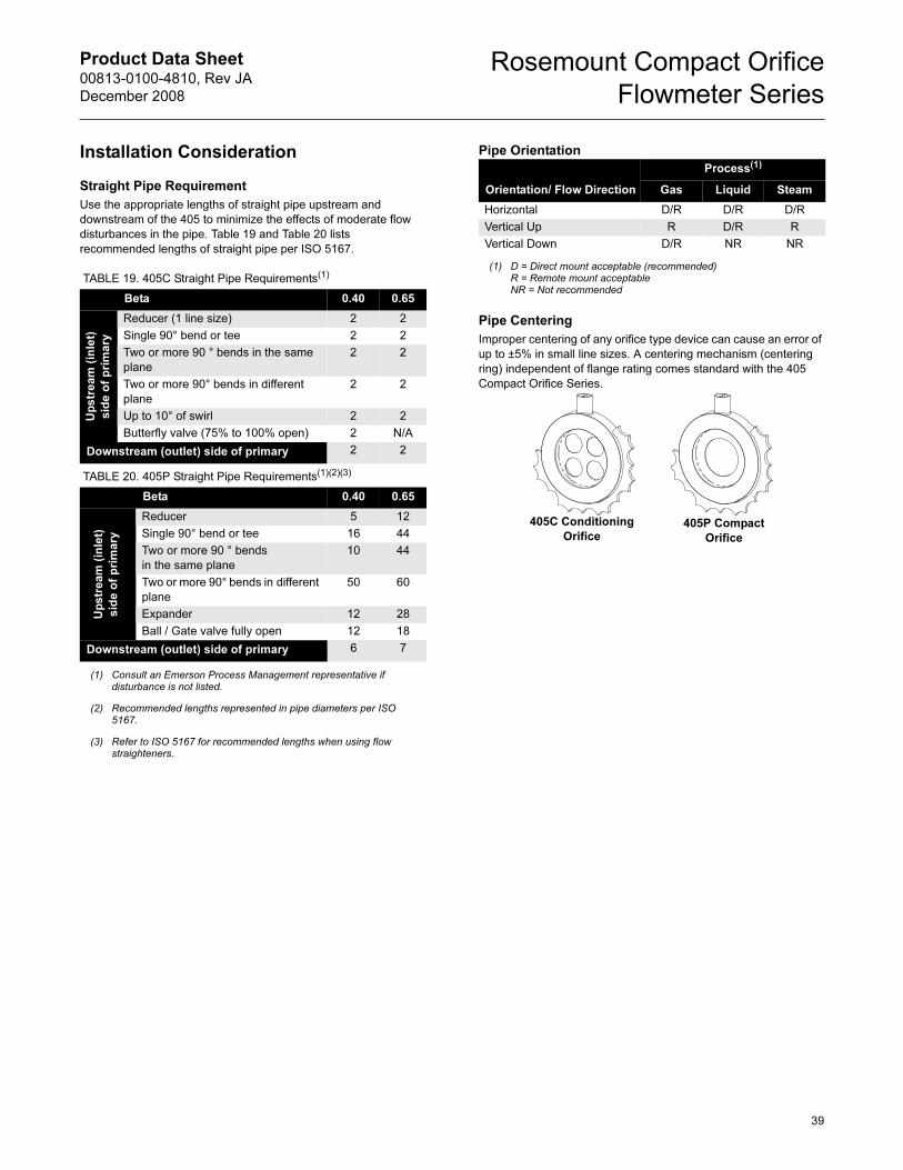
Product Data Sheet00813-0100-4810, Rev JA
December 2008
Rosemount Compact Orifice
Flowmeter Series
Installation Consideration
Straight Pipe Requirement
Use the appropriate lengths of straight pipe upstream and
downstream of the 405 to minimize the effects of moderate flow
disturbances in the pipe. Table 19 and Table 20 lists
recommended lengths of straight pipe per ISO 5167.
Pipe Orientation
Pipe Centering
Improper centering of any orifice type device can cause an error of
up to ±5% in small line sizes. A centering mechanism (centering
ring) independent of flange rating comes standard with the 405
Compact Orifice Series.
TABLE 19. 405C Straight Pipe Requirements(1)
Beta 0.40 0.65
Up
str
ea
m (
inle
t)
sid
e o
f p
rim
ary
Reducer (1 line size) 2 2
Single 90° bend or tee 2 2
Two or more 90 ° bends in the same
plane
2 2
Two or more 90° bends in different
plane
2 2
Up to 10° of swirl 2 2
Butterfly valve (75% to 100% open) 2 N/A
Downstream (outlet) side of primary 2 2
TABLE 20. 405P Straight Pipe Requirements(1)(2)(3)
(1) Consult an Emerson Process Management representative if disturbance is not listed.
Beta 0.40 0.65
(2)(3)
(2) Recommended lengths represented in pipe diameters per ISO 5167.
(3) Refer to ISO 5167 for recommended lengths when using flow straighteners.
Reducer 5 12
Single 90° bend or tee 16 44
Two or more 90 ° bends
in the same plane
10 44
Two or more 90° bends in different
plane
50 60
Expander 12 28
Ball / Gate valve fully open 12 18
Downstream (outlet) side of primary 6 7
Up
str
ea
m (
inle
t)
sid
e o
f p
rim
ary
Orientation/ Flow Direction
Process(1)
(1) D = Direct mount acceptable (recommended)R = Remote mount acceptableNR = Not recommended
Gas Liquid Steam
Horizontal D/R D/R D/R
Vertical Up R D/R R
Vertical Down D/R NR NR
405C Conditioning
Orifice405P Compact
Orifice
39
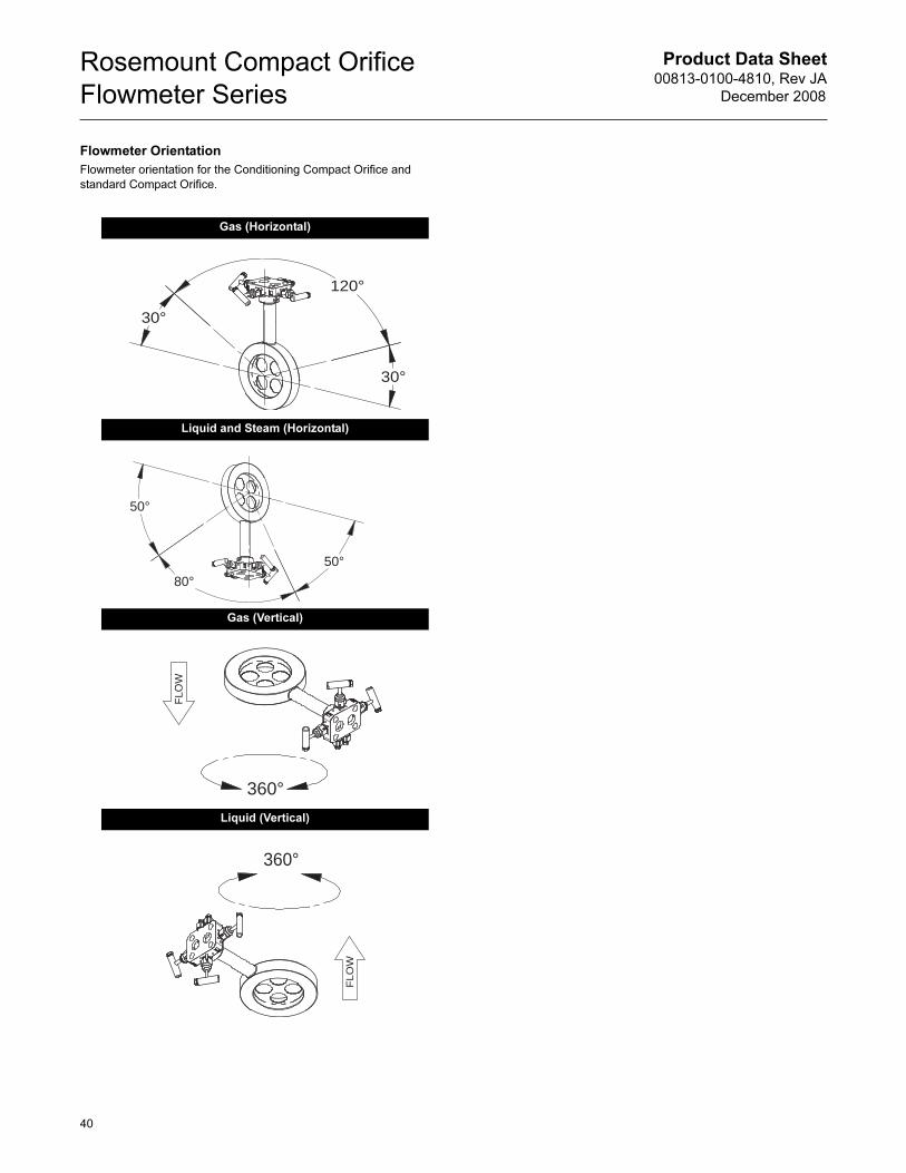
Product Data Sheet00813-0100-4810, Rev JA
December 2008
Rosemount Compact Orifice
Flowmeter Series
Flowmeter Orientation
Flowmeter orientation for the Conditioning Compact Orifice and
standard Compact Orifice.
Gas (Horizontal)
Liquid and Steam (Horizontal)
Gas (Vertical)
Liquid (Vertical)
30°
120°
30°
50°
80°50°
360°
FLO
W
360°
FLO
W
40
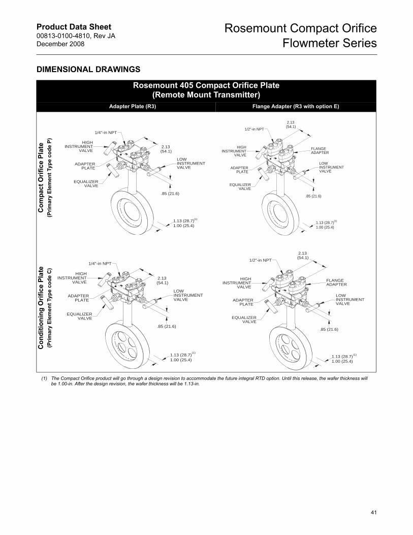
Product Data Sheet00813-0100-4810, Rev JA
December 2008
Rosemount Compact Orifice
Flowmeter Series
DIMENSIONAL DRAWINGS
Rosemount 405 Compact Orifice Plate(Remote Mount Transmitter)
Adapter Plate (R3)(1) Flange Adapter (R3 with option E)
Co
mp
act
Ori
fice P
late
(Pri
ma
ry E
lem
en
t Ty
pe
co
de
P)
Co
nd
itio
nin
g O
rifi
ce P
late
(Pri
ma
ry E
lem
en
t Ty
pe
co
de
C)
(1) The Compact Orifice product will go through a design revision to accommodate the future integral RTD option. Until this release, the wafer thickness will be 1.00-in. After the design revision, the wafer thickness will be 1.13-in.
VALVE
EQUALIZER
1/4"-in NPT
INSTRUMENT
INSTRUMENTHIGH
VALVE
VALVE
LOWADAPTER
PLATE
.85 (21.6)
(54.1)2.13
1.13 (28.7)1.00 (25.4)
(1)
1/2"-in NPT
ADAPTERPLATE
INSTRUMENT
VALVEINSTRUMENT
VALVEEQUALIZER
HIGH
VALVE
LOW
FLANGEADAPTER
1.13 (28.7)1.00 (25.4)
.85 (21.6)
2.13(54.1)
(1)
EQUALIZER
INSTRUMENTHIGH
1/4"-in NPT
VALVE
VALVE
VALVEINSTRUMENTLOW
ADAPTERPLATE
(54.1)
.85 (21.6)
2.13
1.13 (28.7)1.00 (25.4)
(1)
VALVEADAPTER INSTRUMENT
EQUALIZERVALVE
PLATE
INSTRUMENTVALVE
1/2"-in NPT
HIGH
LOW
FLANGEADAPTER
1.13 (28.7)1.00 (25.4)
.85 (21.6)
2.13(54.1)
(1)
41
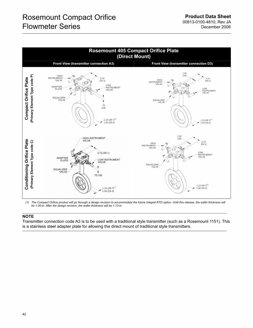
Product Data Sheet00813-0100-4810, Rev JA
December 2008
Rosemount Compact Orifice
Flowmeter Series
NOTE
Transmitter connection code A3 is to be used with a traditional style transmitter (such as a Rosemount 1151). This
is a stainless steel adapter plate for allowing the direct mount of traditional style transmitters.
Rosemount 405 Compact Orifice Plate(Direct Mount)
Front View (transmitter connection A3)(1) Front View (transmitter connection D3)
Co
mp
act
Ori
fice P
late
(Pri
ma
ry E
lem
en
t Ty
pe
co
de
P)
Co
nd
itio
nin
g O
rifi
ce P
late
(Pri
ma
ry E
lem
en
t Ty
pe
co
de
C)
(1) The Compact Orifice product will go through a design revision to accommodate the future integral RTD option. Until this release, the wafer thickness will be 1.00-in. After the design revision, the wafer thickness will be 1.13-in.
INSTRUMENTVALVE
HIGH
VALVEINSTRUMENT
VALVEEQUALIZER
LOWADAPTER
PLATE
2.13
1.13 (28.7)1.00 (25.4)
(54.1)
.70(18)
(1)
HIGH
EQUALIZERVALVE
VALVEINSTRUMENT
LOWINSTRUMENTVALVE
1.30
1.13 (28.7)1.00 (25.4)
(33)2.13(54.1)
(1)
1.13 (28.7)
1.00 (25.4)
(1)
HIGH
EQUALIZERVALVE
VALVEINSTRUMENT
LOWINSTRUMENTVALVE
1.30
1.13 (28.7)1.00 (25.4)
(33)2.13(54.1)
(1)
42
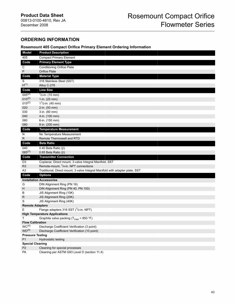
Product Data Sheet00813-0100-4810, Rev JA
December 2008
Rosemount Compact Orifice
Flowmeter Series
ORDERING INFORMATION
Rosemount 405 Compact Orifice Primary Element Ordering Information
Model Product Description
405 Compact Primary Element
Code Primary Element Type
C Conditioning Orifice Plate
P Orifice Plate
Code Material Type
S 316 Stainless Steel (SST)
H(1) Alloy C-276
Code Line Size
005(2) 1/2-in. (15 mm)
010(2) 1-in. (25 mm)
015(2) 11/2-in. (40 mm)
020 2-in. (50 mm)
030 3-in. (80 mm)
040 4-in. (100 mm)
060 6-in. (150 mm)
080 8-in. (200 mm)
Code Temperature Measurement
N No Temperature Measurement
R Remote Thermowell and RTD
Code Beta Ratio
040 0.40 Beta Ratio (β)
065(3) 0.65 Beta Ratio (β)
Code Transmitter Connection
D3 Coplanar, Direct mount, 3-valve Integral Manifold, SST
R3 Remote-mount, 1/4-in. NPT connections
A3 Traditional, Direct mount, 3-valve Integral Manifold with adapter plate, SST
Code Options
Installation Accessories
G DIN Alignment Ring (PN 16)
H DIN Alignment Ring (PN 40, PN 100)
B JIS Alignment Ring (10K)
R JIS Alignment Ring (20K)
S JIS Alignment Ring (40K)
Remote Adapters
E Flange adapters 316 SST (1/2-in. NPT)
High Temperature Applications
T Graphite valve packing (Tmax = 850 °F)
Flow Calibration
WC(4) Discharge Coefficient Verification (3 point)
WD(4) Discharge Coefficient Verification (10 point)
Pressure Testing
P1 Hydrostatic testing
Special Cleaning
P2 Cleaning for special processes
PA Cleaning per ASTM G93 Level D (section 11.4)
43
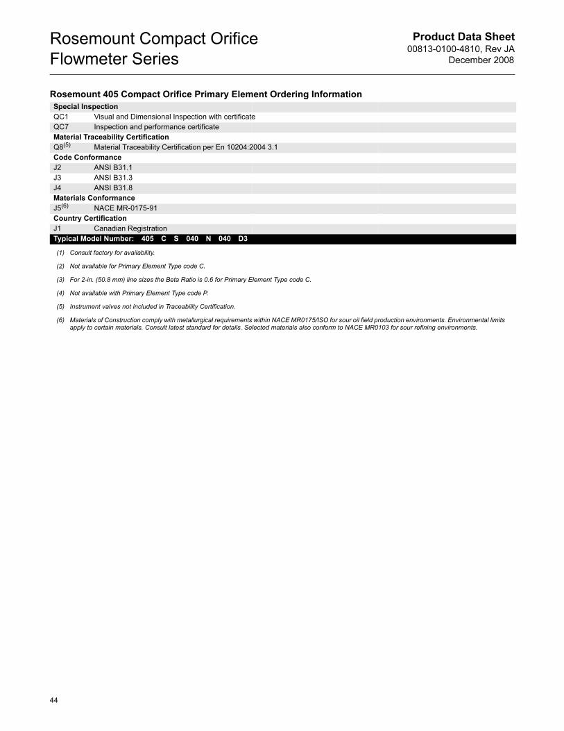
Product Data Sheet00813-0100-4810, Rev JA
December 2008
Rosemount Compact Orifice
Flowmeter Series
Special Inspection
QC1 Visual and Dimensional Inspection with certificate
QC7 Inspection and performance certificate
Material Traceability Certification
Q8(5) Material Traceability Certification per En 10204:2004 3.1
Code Conformance
J2 ANSI B31.1
J3 ANSI B31.3
J4 ANSI B31.8
Materials Conformance
J5(6) NACE MR-0175-91
Country Certification
J1 Canadian Registration
Typical Model Number: 405 C S 040 N 040 D3
(1) Consult factory for availability.
(2) Not available for Primary Element Type code C.
(3) For 2-in. (50.8 mm) line sizes the Beta Ratio is 0.6 for Primary Element Type code C.
(4) Not available with Primary Element Type code P.
(5) Instrument valves not included in Traceability Certification.
(6) Materials of Construction comply with metallurgical requirements within NACE MR0175/ISO for sour oil field production environments. Environmental limits apply to certain materials. Consult latest standard for details. Selected materials also conform to NACE MR0103 for sour refining environments.
Rosemount 405 Compact Orifice Primary Element Ordering Information
44
Product Data Sheet00813-0100-4810, Rev JA
December 2008
Rosemount Compact Orifice
Flowmeter Series
45
Product Data Sheet00813-0100-4810, Rev JA
December 2008
Rosemount Compact Orifice
Flowmeter Series
Standard Terms and Conditions of Sale can be found at www.rosemount.com/terms_of_saleThe Emerson logo is a trade mark and service mark of Emerson Electric Co. Rosemount, the Rosemount logotype, ProPlate, Mass ProPlate, and Annubar are registered trademarks of Rosemount Inc.WAGO is a registered trademark of WAGO KontakHechnik GmbH, Germany.Fluorinert is a registered trademark of 3M Company.All other marks are the property of their respective owners.© 2008 Rosemount, Inc. All rights reserved.
00813-0100-4810 Rev JA, 12/08
Emerson Process Management Blegistrasse 23P.O. Box 1046CH 6341 BaarSwitzerlandTel +41 (0) 41 768 6111Fax +41 (0) 41 768 6300
Emerson Process Management Asia Pacific Pte Ltd1 Pandan CrescentSingapore 128461Tel +65 6777 8211Fax +65 6777 0947Service Support Hotline : +65 6770 8711Email : [email protected]
Emerson Process ManagementRosemount Measurement8200 Market BoulevardChanhassen MN 55317 USATel (USA) 1 800 999 9307Tel (International) +1 952 906 8888Fax +1 952 949 7001
Emerson FZEP.O. Box 17033Jebel Ali Free ZoneDubai UAETel +971 4 811 8100Fax +971 4 886 5465