Embed Size (px)
Citation preview

Operator’s Manual
Roller
������������
0085214D0194
0 0 8 5 2 1 4


Information Contained InThis Manual
This manual provides information and procedures tosafely operate and maintain the WACKER RT 560 and RT820 Trench Rollers. This machine is equipped with a two-cylinder Lombardini diesel engine.
For your own safety and protection from physicalinjury, carefully read, understand, and observe thesafety instructions described in this manual.
Always operate and maintain your machine in accor-dance with the instructions described in this manual. Awell maintained machine will provide many years oftrouble-free operation.
This book is divided into two sections:
General Operating Information
Infra-Red Remote Control Operation
Ordering Parts
A Parts Manual is available for this machine and canbe ordered using P/N 85215.
Additional Engine Information
A manual for the engine was supplied with the machineat the time of its shipment from the factory. Thismanual provides detailed maintenance procedures forthe engine.
For additional service information on the engine, orderWork Shop Manual, P/N 74232.
FOREWORD
This Manual covers machines withSerial Numbers beginning:
6594, 65956784, 6785
Keep a copy of this manual with the machine. If a manualbecomes lost or additional copies are desired, please
contact WACKER Corporation.
1
2
THE INFORMATION CONTAINED IN THIS MANUAL WAS BASED ON MACHINES IN PRODUCTION AT THE TIME OF PUBLICATION.WACKER CORPORATION RESERVES THE RIGHT TO CHANGE ANY PORTION OF THIS INFORMATION WITHOUT NOTICE.

FOREWORD
Identification Plate
Serial Number
Production Sequence
Model Identification
6594 00123The serial number found on the identification plate is anine digit number. The first four digits identify thespecific machine model (Bill of Material). The last fivenumbers indicate the production sequence for thatmodel.
An identification plate listing the Model Number and Serial Number is attached to each machine and is locatedinside on the control panel. This plate should not be removed from the machine.
Please record the information found on this plate so it will be available should the identification plate become lostor damaged. When ordering parts or requesting service information you will always be asked to specify the modeland serial number of the unit.
The serial number identifies your machine and willensure that you receive the correct replacement parts.
WACKERCORPORATION
Model
Serial No.
Weight
Year
````
1002SD33

4
1-1
RT560/RT820General Operating Information
Table of ContentsPage
SAFETY1.1 Safety Notes ..................................... 1-21.2 Operating Safety ............................... 1-31.3 Engine Safety.................................... 1-31.4 Service Safety .................................. 1-4
TECHNICAL DATA1.5 Engine ............................................... 1-51.6 Roller ................................................. 1-51.7 Lubrication ........................................ 1-5
OPERATION1.8 Controls & Service Locations- Roller 1-61.9 Service Locations - Engine ............... 1-71.10 Before Starting .................................. 1-81.11 Starting .............................................. 1-81.12 Stopping ............................................ 1-81.13 Travel ................................................ 1-81.14 Direction & Steering Control ............. 1-81.15 Vibration ............................................ 1-91.16 Safety Bar ......................................... 1-91.17 Operation on Slopes ......................... 1-91.18 Engine Speed.................................. 1-101.19 Engine Oil Pressure Light ............... 1-101.20 Charging System Light ................... 1-101.21 Hour Meter ...................................... 1-101.22 Articulated Joint Locking Pin ........... 1-101.23 Automatic Engine Shut-off .............. 1-10
PageMAINTENANCE
1.24 Engine Fuel Delivery System ......... 1-111.25 New Machines ................................ 1-111.26 Periodic Maintenance Schedule ..... 1-111.27 Air Cleaner ...................................... 1-121.28 Engine Lubrication .......................... 1-121.29 Articulated Joint & Steering Cyl. ..... 1-121.30 Drive Gearcase .............................. 1-131.31 Exciter ............................................. 1-131.32 Engine Valve Clearance ................. 1-131.33 Fuel Filter ........................................ 1-141.34 Priming Fuel System ....................... 1-141.35 Cleaning Engine Cylinder Cooling Fins ..................................... 1-141.36 Scraper Bars .................................. 1-141.37 Shockmounts .................................. 1-141.38 Hydraulic Oil Requirements ............ 1-151.39 Changing Hydraulic Fluid & Filter.... 1-151.40 Hydraulic Fluid Level ...................... 1-151.41 Transporting Machine ..................... 1-161.42 Lifting Machine ................................ 1-161.43 Changing Drums ............................. 1-161.44 Battery ............................................ 1-171.45 Tightening Hardware ....................... 1-171.46 Jobsite Storage ............................... 1-171.47 Long Term Storage ......................... 1-17
TROUBLESHOOTING1.48 General ........................................... 1-181.49 Hydraulic Schematic ....................... 1-191.50 Control Box Wiring .......................... 1-201.51 Relay Panel and Engine Wiring ...... 1-21
(W/15 Amp Vibration Relay Fuse)1.52 Relay Panel and Engine Wiring ...... 1-22
(W/O 15 Amp Vibration Relay Fuse)
1
1-2
1
WACKER equipment is designed with user safety in mind. Whenproperly maintained and used by trained operators in the applica-tions for which it was intended, this machine will provide many yearsof safe, reliable service.
Should questions arise during the operation or service of this equip-ment please contact your area WACKER Customer Support Center.A complete listing of Support Centers appears on the front and rearcovers of this manual.
CAUTION
WARNING
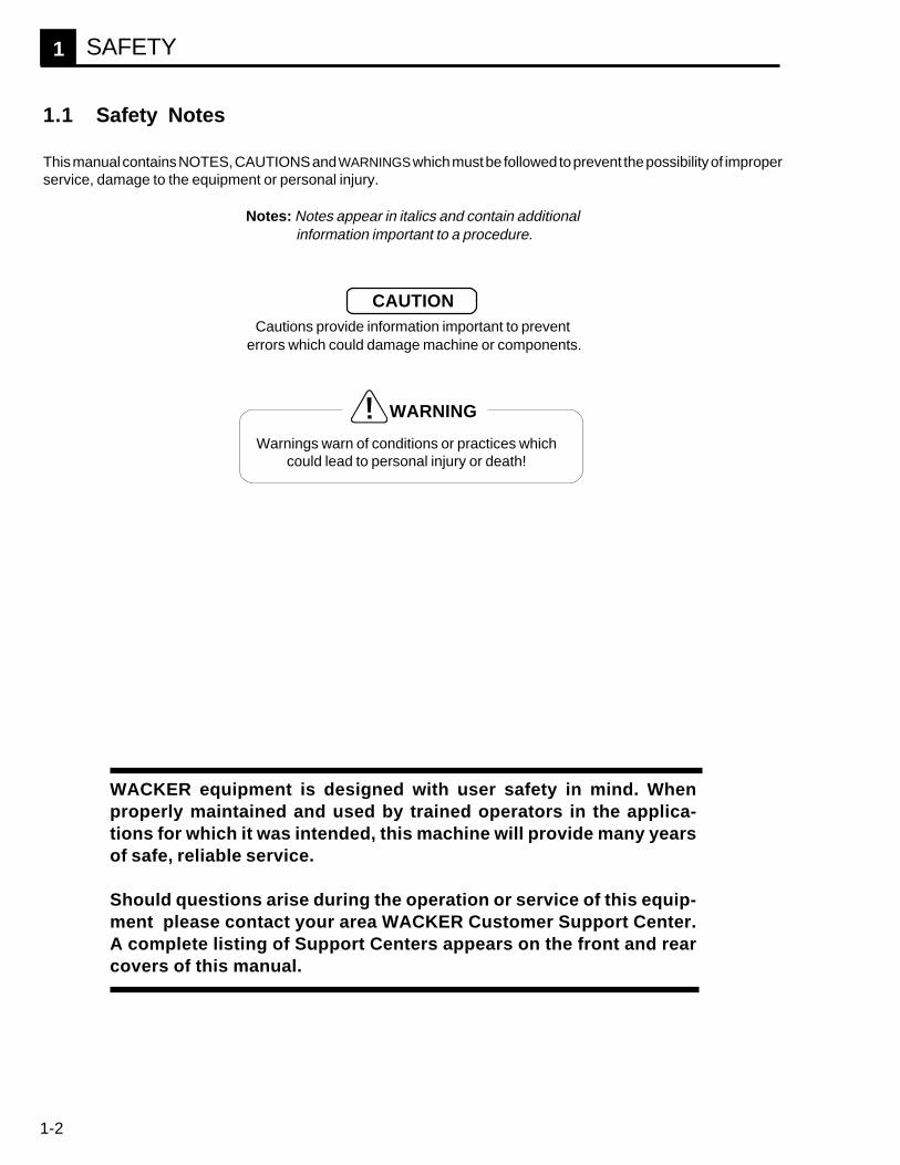
Warnings warn of conditions or practices whichcould lead to personal injury or death!
1.1 Safety Notes
This manual contains NOTES, CAUTIONS and WARNINGS which must be followed to prevent the possibility of improperservice, damage to the equipment or personal injury.
Notes: Notes appear in italics and contain additional information important to a procedure.
Cautions provide information important to prevent errors which could damage machine or components.
SAFETY
1-3
1
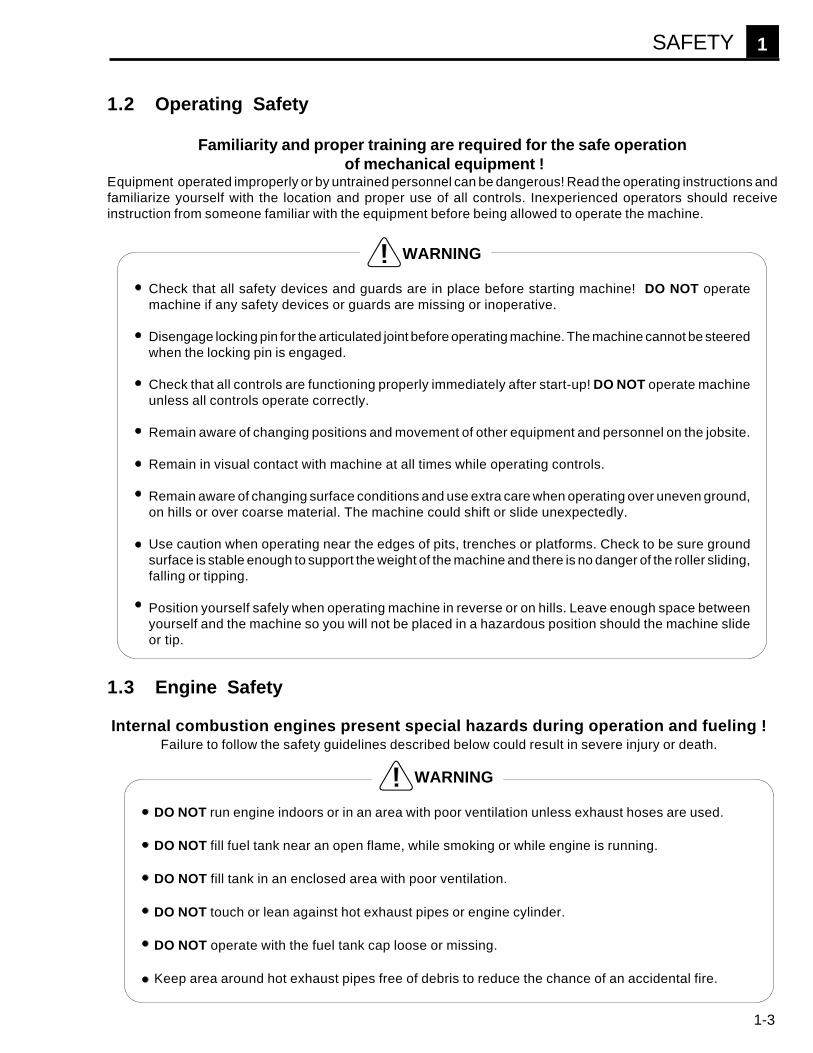
1.2 Operating Safety
Familiarity and proper training are required for the safe operation of mechanical equipment !
Equipment operated improperly or by untrained personnel can be dangerous! Read the operating instructions andfamiliarize yourself with the location and proper use of all controls. Inexperienced operators should receiveinstruction from someone familiar with the equipment before being allowed to operate the machine.
Check that all safety devices and guards are in place before starting machine! DO NOT operatemachine if any safety devices or guards are missing or inoperative.
Disengage locking pin for the articulated joint before operating machine. The machine cannot be steeredwhen the locking pin is engaged.
Check that all controls are functioning properly immediately after start-up! DO NOT operate machineunless all controls operate correctly.
Remain aware of changing positions and movement of other equipment and personnel on the jobsite.
Remain in visual contact with machine at all times while operating controls.
Remain aware of changing surface conditions and use extra care when operating over uneven ground,on hills or over coarse material. The machine could shift or slide unexpectedly.
Use caution when operating near the edges of pits, trenches or platforms. Check to be sure groundsurface is stable enough to support the weight of the machine and there is no danger of the roller sliding,falling or tipping.
Position yourself safely when operating machine in reverse or on hills. Leave enough space betweenyourself and the machine so you will not be placed in a hazardous position should the machine slideor tip.
WARNING
DO NOT run engine indoors or in an area with poor ventilation unless exhaust hoses are used.
DO NOT fill fuel tank near an open flame, while smoking or while engine is running.
DO NOT fill tank in an enclosed area with poor ventilation.
DO NOT touch or lean against hot exhaust pipes or engine cylinder.
DO NOT operate with the fuel tank cap loose or missing.
Keep area around hot exhaust pipes free of debris to reduce the chance of an accidental fire.
WARNING
1.3 Engine Safety
Internal combustion engines present special hazards during operation and fueling !Failure to follow the safety guidelines described below could result in severe injury or death.
SAFETY

1-4
1
1.4 Service Safety
Poorly maintained equipment can become a safety hazard !In order for the equipment to operate safely and properly over a long period of time periodic maintenance andoccasional repairs are necessary.
Replace all guards and safety devices immediately after servicing.
Turn engine off before performing maintenance or making repairs.
Secure the articulated joint using the locking pin before lifting or jacking machine up. Machine halvescould swing together unexpectedly and cause a serious injury if this is not done.
DO NOT open hydraulic lines or loosen hydraulic connections while engine is running! Hydraulic fluidunder pressure can penetrate the skin, cause burns, blind or create other potentially dangerous hazards.Set all controls in neutral and turn engine off before loosening hydraulic lines.
Keep hands, feet and loose clothing away from moving parts.
Replace all missing and hard to read decals. See Parts Manual.
Check and tighten all external fasteners at regular intervals.
Make sure slings, chains, hooks, ramps, jacks and other types of lifting devices are attached securelyand have enough weight bearing capacity to lift or hold the machine safely. Always remain aware ofthe position of other people around you when lifting the machine.
DO NOT modify the equipment without expressed written approval from WACKER Corporation.
WARNING
SAFETY
1-5
1
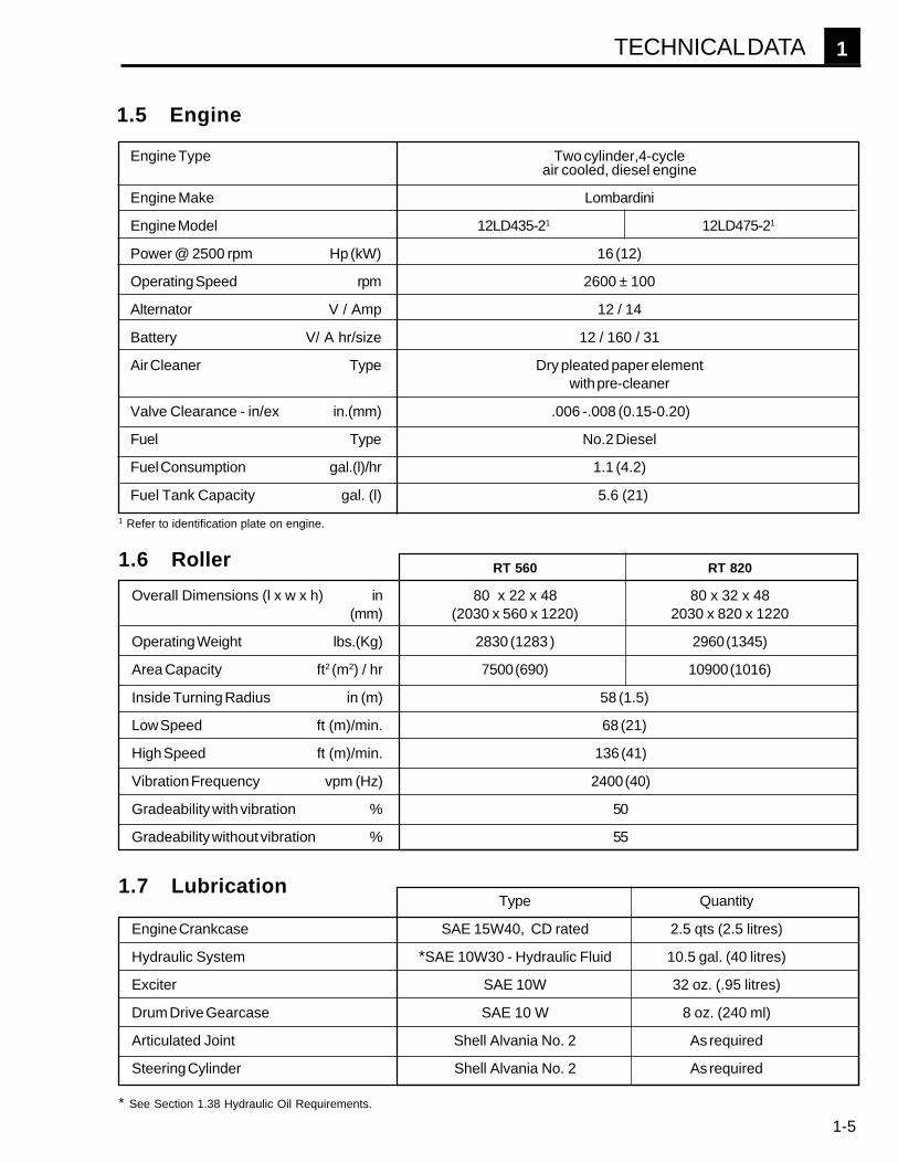
Engine Type Two cylinder,4-cycleair cooled, diesel engine
Engine Make Lombardini
Engine Model 12LD435-21 12LD475-21
Power @ 2500 rpm Hp (kW) 16 (12)
Operating Speed rpm 2600 ± 100
Alternator V / Amp 12 / 14
Battery V/ A hr/size 12 / 160 / 31
Air Cleaner Type Dry pleated paper elementwith pre-cleaner
Valve Clearance - in/ex in.(mm) .006 -.008 (0.15-0.20)
Fuel Type No.2 Diesel
Fuel Consumption gal.(l)/hr 1.1 (4.2)
Fuel Tank Capacity gal. (l) 5.6 (21)
1.5 Engine
Type Quantity
Engine Crankcase SAE 15W40, CD rated 2.5 qts (2.5 litres)
Hydraulic System *SAE 10W30 - Hydraulic Fluid 10.5 gal. (40 litres)
Exciter SAE 10W 32 oz. (.95 litres)
Drum Drive Gearcase SAE 10 W 8 oz. (240 ml)
Articulated Joint Shell Alvania No. 2 As required
Steering Cylinder Shell Alvania No. 2 As required
1.7 Lubrication
* See Section 1.38 Hydraulic Oil Requirements.
TECHNICAL DATA
1 Refer to identification plate on engine.
RT 560 RT 820
Overall Dimensions (l x w x h) in 80 x 22 x 48 80 x 32 x 48(mm) (2030 x 560 x 1220) 2030 x 820 x 1220
Operating Weight lbs.(Kg) 2830 (1283 ) 2960 (1345)
Area Capacity ft2 (m2) / hr 7500 (690) 10900 (1016)
Inside Turning Radius in (m) 58 (1.5)
Low Speed ft (m)/min. 68 (21)
High Speed ft (m)/min. 136 (41)
Vibration Frequency vpm (Hz) 2400 (40)
Gradeability with vibration % 50
Gradeability without vibration % 55
1.6 Roller

1-6
1
c d e
f
g
jk if
g
ba
1.8 Controls & Service Locations - Roller
x
yhi
b
aa
bb
z
cc
OPERATION
1002SD34
l m u
o
vw t qn2
s
SEENOTE *
r
dd
1006SD32
LEVER TYPE THROTTLE CONTROL
[AVAILABLE WITH PULL TYPETHROTTLES (n2
) ONLY]
n1
p

1-7
1
a b
g h ie fc
1.9 Service Locations - Engine
j
d
k
Rollera Fuel Filter & Oil Dipstick Access Door
Oil Filter Access Door (opposite side)b Steering Cylinder Grease Fittingc Lifting Eyed Steering Cylinder Access Panele Safety Barf Shockmountg Tie Down Lugh Scraper Bari Articulated Joint Grease Fittingj Articulated Joint Locking Pink Exciter Oil Level Sight Plugl Hydraulic Tank Ventm Hydraulic Tank Return Line Filtern1 Engine Throttle Control (Lever Type)n2 Engine Throttle Control (Pull Type)
* Note: For machines equipped for infra-red remote control see "REMOTE CONTROL SYSTEM", starting on page 2-1.
Enginea Air Cleanerb Fuel Line Bleed Screwc Oil Dipstickd Oil Pressure Switch (Warning Light)e Fuel Pumpf Fuel Filter
g Voltage Regulatorh Oil Filteri Oil Pressure Sending Unit (Engine Shut Down)j Fuel Filter Bleed Screwk Filter Indicator for Air Cleaner
OPERATION
1002SD361002SD35
o Padlock Ringp Control Boxq Hour Meterr Charging System Warning Lights Engine Oil Pressure Warning Lightt Fuel Capu Hydraulic Oil Level Sight Gaugev Fuel Tank Ventw Batteryx Drive Case Fill Plugy Drive Case Drain Plugz Oil Level Plugaa Engine Oil Drain Plugbb Drum Pusher Holescc Fuel Tank Drain Plugdd Control Box Storage Area
1-8
1
EXCITER
HI
OFF
LO
TRAVEL
HI
LO
OFF
RUN
START
1.10 Before Starting
Before starting machine check the following:
1. Engine oil level.2. Condition of air cleaner.3. Fuel level.4. Hydraulic fluid level.5. Position of locking pin at articulated joint.
1.11 Starting
1. Check that vibration switch (a) is set to "OFF".
2. Set throttle control between 1/2 - 3/4 open.
3. Turn ignition switch (c) on control box to "START"and crank starter until engine starts. Leave key switchin the "RUN" position while operating machine.
Note: On machines equipped with Infra-red remotecontrol, set the Remote/Cord selector switch to "CORDCONTROL". The machine can now only be startedusing the control box. See "REMOTE CONTROLSYSTEM" , page 2-5, for start up procedures usingthe infra-red transmitter.
DO NOT crank engine more than 15-20 seconds at atime or starter motor may overheat. Wait 30-45seconds between start-up attempts so starter motorcan cool down.
Note: The engine is equipped with a low oil shut downfeature. If the engine does not start, check both thefuel and engine oil levels.
4. After engine starts, open throttle completely. Allowengine to warm up for a few minutes before operatingmachine.
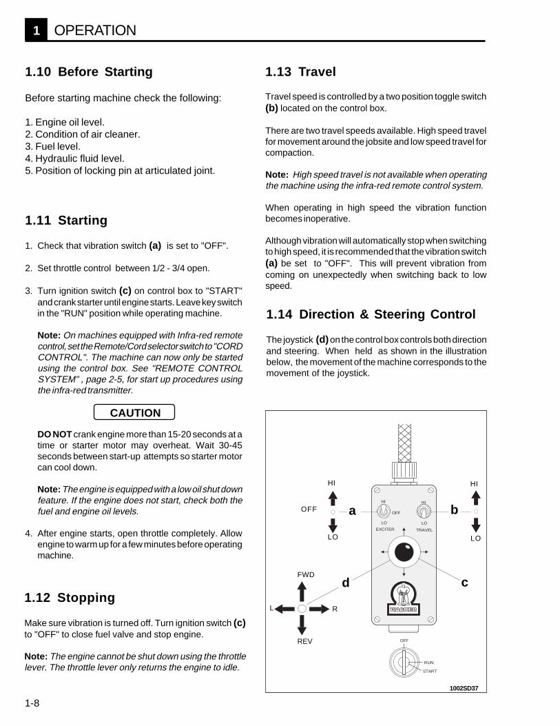
1.13 Travel
Travel speed is controlled by a two position toggle switch(b) located on the control box.
There are two travel speeds available. High speed travelfor movement around the jobsite and low speed travel forcompaction.
Note: High speed travel is not available when operatingthe machine using the infra-red remote control system.
When operating in high speed the vibration functionbecomes inoperative.
Although vibration will automatically stop when switchingto high speed, it is recommended that the vibration switch(a) be set to "OFF". This will prevent vibration fromcoming on unexpectedly when switching back to lowspeed.
CAUTION
1.12 Stopping
Make sure vibration is turned off. Turn ignition switch (c)to "OFF" to close fuel valve and stop engine.
Note: The engine cannot be shut down using the throttlelever. The throttle lever only returns the engine to idle.
HI
cd
OFF
d
a b
L
HI
LO LO
REV
FWD
R
1.14 Direction & Steering Control
The joystick (d) on the control box controls both directionand steering. When held as shown in the illustrationbelow, the movement of the machine corresponds to themovement of the joystick.
OPERATION
1002SD37

1-9
1
1.15 Vibration
There are two vibration modes available. Low amplitudevibration for loose soils with granular content such asgravel, and high amplitude vibration for cohesive typesoils like clay.
Vibration is only available with the machine in the lowspeed travel mode.
Vibration is controlled by a three position switch locatedon the control box. To start vibration, set machine to lowspeed travel, then flip vibration switch to either highamplitude or low amplitude vibration.
Position switch in the off position to stop vibration.
Because the exciter weights must reverse direction whenswitching between vibration modes, there is a ten seconddelay built into the vibration circuit. This allows time for theweights to come to a complete stop.
� � � �
1.17 Operation on Slopes
When operating on slopes or hills special care must betaken to reduce the risk of personal injury or damage to theequipment. Whenever possible operate machine up anddown hills rather than from side to side to improve stabilityand reduce the possibility of a roll over. We recommendthat for safe operation restrict use to slopes of 14° (25%grade) or less.
NEVER operate machine on side slopes greater than26°(50% grade). At slopes greater than this themachine may roll over, even on stable ground.
26°50%
WARNING
LO
HI
LO
OFF
1.16 Safety Bar
A safety bar is mounted to the rear section of the machinebehind the control panel.
If the machine backs into an obstruction or for somereason the operator becomes trapped behind it, the bar willbe pressed forward and stop the machine. The machinewill resume reverse travel when the bar is released.
OPERATION
1002SD38
1002SD39
1002SD40

1-10
1
� � � �
q r s
1.22 Articulated Joint Locking Pin
A locking pin is provided to secure the front and rearhalves of the machine together.
When lifting the machine secure the articulated joint withthe locking pin as shown (a). When operating the machinestore the locking pin in the storage hole (b).
1.21 Hour Meter
The hour meter (q) will run only with the ignition switchin the "on" position and the engine running.
1.23 Automatic Engine Shut-off
The engine will automatically shut down, if oil pressurefalls below 4 psi (0.3 bar).
If the engine stops unexpectedly during operation, checkengine oil level before resuming operation.
b
1.18 Engine Speed
During operation run engine at full throttle (2600 rpm). This ensures maximum exciter speed and will produce the bestcompaction.
a
CAUTION
CAUTION
1.19 Engine Oil Pressure Light
The oil pressure warning light (s) will come on when oilpressure falls to 7 psi (0.5 bar).
DO NOT continue to operate machine with warning light onor engine damage may occur. Stop engine and check oillevel.
1.20 Charging System Light
The engine is equipped with an alternator and voltageregulator to maintain the battery charge. The chargingsystem warning light (r) indicates the condition of thebattery charging system. Although the machine will runwith the light on for a short period of time, continuedoperation will drain the battery and eventually cause themachine to lose all operating functions.
If operating machine in a narrow trench or other confinedarea, drive machine into a safer area as soon as possibleto avoid stranding it in a hazardous or inaccessiblelocation.
OPERATION
1002SD42
1006SD33

1-11
1
Maintenance to the engine fuel delivery system should be performed by an experienced mechanic familiar with dieselengines. For detailed maintenance procedures on the engine fuel system, refer to the engine manual, supplied with themachine at time of shipment.
1.24 Engine Fuel Delivery System Maintenance
1.25 New Machines
Perform the following after the first 50 hours of operation.
1. Change engine oil and replace oil filter after first 50 hours.2. Replace hydraulic return line filter after first month or 100 hours.
Check engine oil. Fill to correct level.
Check hydraulic oil. Fill to correct level.
Check air filter. Replace as required.
Grease articulated joint.
Grease steering cylinder.
Check battery fluid level.
Clean engine head and cylinder fins.
Change oil in engine crankcase.
Replace engine oil filter.
Replace fuel filter cartridge.
Check valve clearance.
Clean injectors and check injector pressure.
Clean battery terminals
Change oil in drive gear case.
Change hydraulic system return line filter.
Change hydraulic fluid.
Change exciter oil.
Daily Every Every Every EveryBefore 100 300 500 1000Starting Hours Hours Hours hours
1.26 Periodic MaintenanceSchedule
MAINTENANCE
Every two years

1-12
1
1.27 Air Cleaner
Inspect air cleaner daily and replace as needed. Onmachines equipped with a filter indicator, replace filterelement when red poppet in indicator pops up.
The air cleaner assembly consists of a mesh pre-cleaner, a dry type pleated paper element, o-ring andcover.
To inspect air cleaner:Remove cover and inspect paper element. Replacepaper element if it appears heavily soiled or engine haslost power. Line up tabs on cover with slots in housingand install cover. Be sure cover is seated tightlyagainst o-ring. If o-ring is damaged it must bereplaced.The pre-cleaner can be washed using eithersoap and water, or diesel fuel.
If the pre-cleaner is washed in diesel fuel, it must drycompletely before installing it back in air cleaner orengine may race when started.
1.28 Engine Lubrication
Check engine oil level daily. Add oil as required.Change oil and oil filter every 100 hours. On newmachines change oil after first 50 hours of operation.
To check oil:Place machine on a level surface, remove dipstick andcheck that oil level is at top mark. Add oil through oilfiller cap (a) on top of engine checking occasionallywith dipstick. DO NOT overfill.
Use SAE 15W40 oil, rated CD.
Note: If oil level falls too low causing oil pressure todrop below preset value, engine will not start or mayshut down during operation.
i
b b
CAUTION
1.29 Articulated Joint & SteeringCylinder
Lubricate top and bottom bearing blocks (i) and cylinderknuckles (b) every 100 hours using a hand held greasegun.
Use Shell Alvainia No. 2 or an equivalent No. 2 generalpurpose grease.
a
MAINTENANCE
1002SD45
1002SD43
1002SD44

1-13
1
1.30 Drive Gearcase
Change the oil in the drive gearcase once a year or every500 hours of operation.
To change oil:1. Remove drum from drivecase side of machine. On the
front drum this will be on the right side, on the rear drumit is the left side.
2. Open fill plug (x) for venting and then remove drainplug (y) from bottom of drum assembly.
3. Install drain plug and remove level plug (z) fromgearcase.
4. Add SAE 10W oil through fill plug opening until oil flowsout of level plug opening, approx. 8 oz. ( 240 ml).
5. Replace plugs and install drum.z
y
x
MAINTENANCE
1002SD46
1.32 Engine Valve Clearance
Check and adjust valve clearance every 500 hours.
Remove rocker arm cover and check gaskets for break-age. Set clearance with engine cold. Bring each cylinderpiston to top dead center on the compression stroke andset clearance.
Valve clearance .006 - 008 in. (0.15 - 0.20 mm).
Replace cover and tighten to 14 ft. lbs. (19 Nm). .006"-.008"(0.15 - 0.20 mm)
1002SD48
1.31 Exciter
The exciter is a sealed unit and under normal conditionsshould not require any periodic maintenance, however, anoil change once every two years is recommended toensure bearing life.
Changing the exciter oil requires special tools and shouldbe performed by an experienced mechanic. Please con-tact a WACKER Customer Support Center.
Note: Exciters on early production machines were equippedwith a sightglass to check oil level. To view sightglass,remove plug (k) from drum cover.
k
1002SD47
1-14
1
f
j
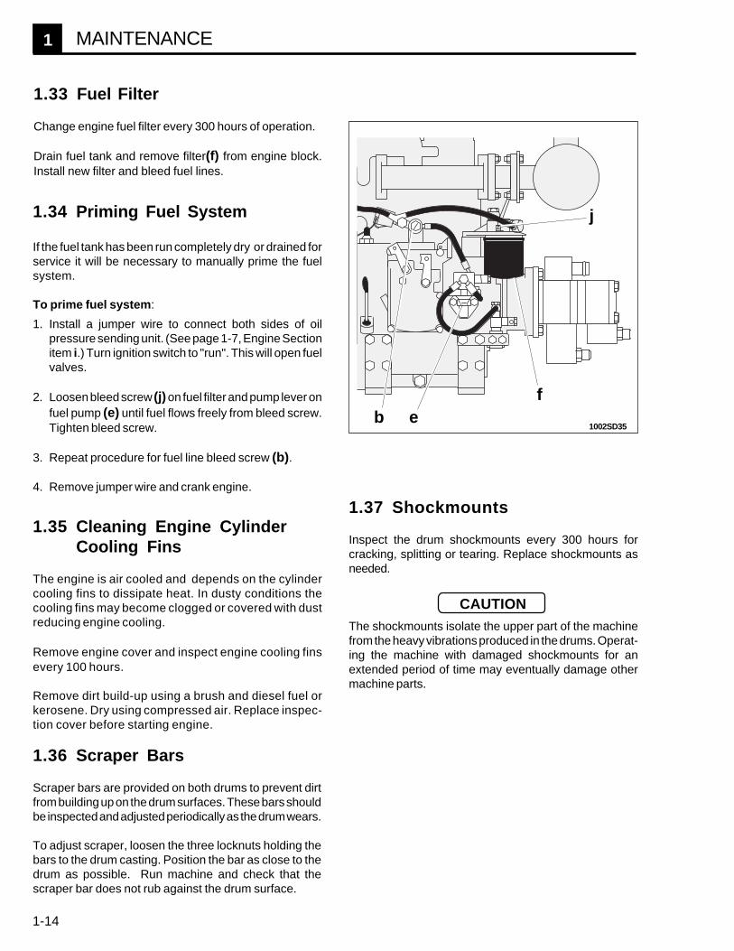
1.33 Fuel Filter
Change engine fuel filter every 300 hours of operation.
Drain fuel tank and remove filter(f) from engine block.Install new filter and bleed fuel lines.
b e
CAUTION
1.37 Shockmounts
Inspect the drum shockmounts every 300 hours forcracking, splitting or tearing. Replace shockmounts asneeded.
The shockmounts isolate the upper part of the machinefrom the heavy vibrations produced in the drums. Operat-ing the machine with damaged shockmounts for anextended period of time may eventually damage othermachine parts.
MAINTENANCE
1002SD35
1.36 Scraper Bars
Scraper bars are provided on both drums to prevent dirtfrom building up on the drum surfaces. These bars shouldbe inspected and adjusted periodically as the drum wears.
To adjust scraper, loosen the three locknuts holding thebars to the drum casting. Position the bar as close to thedrum as possible. Run machine and check that thescraper bar does not rub against the drum surface.
1.35 Cleaning Engine CylinderCooling Fins
The engine is air cooled and depends on the cylindercooling fins to dissipate heat. In dusty conditions thecooling fins may become clogged or covered with dustreducing engine cooling.
Remove engine cover and inspect engine cooling finsevery 100 hours.
Remove dirt build-up using a brush and diesel fuel orkerosene. Dry using compressed air. Replace inspec-tion cover before starting engine.
1.34 Priming Fuel System
If the fuel tank has been run completely dry or drained forservice it will be necessary to manually prime the fuelsystem.
To prime fuel system:
1. Install a jumper wire to connect both sides of oilpressure sending unit. (See page 1-7, Engine Sectionitem i.) Turn ignition switch to "run". This will open fuelvalves.
2. Loosen bleed screw (j) on fuel filter and pump lever onfuel pump (e) until fuel flows freely from bleed screw.Tighten bleed screw.
3. Repeat procedure for fuel line bleed screw (b).
4. Remove jumper wire and crank engine.

1-15
1
1.38 Hydraulic Oil Requirements
WACKER recommends the use of a premium grade,petroleum based hydraulic oil with anti-wear and anti-foamcharacteristics. Good anti-wear oils contain zinc andmolybdenum additives to reduce oxidation, prevent foam-ing, and provide for good water separation. These oilsoffer superior motor and pump life.
When selecting hydraulic fluid for your machine be sure tospecify anti-wear properties. WACKER offers a premiumgrade hydraulic oil for use in this machine. In addition toits anti-wear properties, this oil has been colored to makeit easier to view in the sight glass and spot hydraulic leaks.
WACKER Hydraulic Oil - P/N 85094
Avoid mixing different brands and grades of hydraulicfluids.
Oil ViscosityMost hydraulic oils are available in different viscosities.The SAE number for an oil is used strictly to identifyviscosity. It does not indicate the type of oil (engine,hydraulic, gear, etc.) The higher the SAE number, thethicker the oil.
For normal applications use a good non-detergent, anti-wear, hydraulic oil rated at SAE 10W30.
1.39 Changing Hydraulic Fluid &Filter
1. Remove drain plug from bottom of hydraulic tank andallow hydraulic fluid to drain.
2 Clean filter housing cover. Remove cover from thefilter housing and remove the filter element (m).
Be extremely careful to avoid dropping anything intothe filter housing while cover is off.
3. Install drain plug.
4. Fill hydraulic tank through filter housing using cleanhydraulic fluid.
5. Install new filter element and replace housing cover.
CAUTION
1002SD49
1.40 Hydraulic Fluid Level
A hydraulic oil level sight gauge is located on the hydraulictank inside the rear section of the machine.
Check that the oil level is within one inch to the top of thesight gauge. Add oil as required through the filter housingon top of hydraulic tank.
If hydraulic oil continually needs to be added, inspecthoses and connections for possible leaks. Repair hydrau-lic leaks immediately to prevent damage to hydrauliccomponents.
MAINTENANCE

1-16
1
1.41 Transporting Machine
When transporting the machine place blocks in front ofand behind each drum and use the tie down lugs (g)provided to securely fasten the machine to the trailer.
1.42 Lifting Machine
Secure front and rear machine halves together using thelocking pin (j) at the articulated joint. Place sling or chainthrough the central lifting eye (c) on the machine. Use alifting device with sufficient weight bearing capacity.
ALWAYS lock the articulated joint before lifting themachine.
c
j
g g
1.43 Changing Drums
The drums can be changed to adjust the working width ofthe machine. Drums are available in two sizes and providea working width of either 32 in. (820 mm) or 22in. (560 mm).
To change drum:
1. Lock the articulated joint.
2. Remove scraper bars.
3. Use a screw jack, hoist or other type of lifting deviceto lift drums one or two inches (25-50 mm) off theground. Lift only one end of the machine. Keep theother end in contact with the ground for stability.
4. Use a 22mm wrench and remove the six screws whichhold the drum to the drum support.
5. Remove the three plugs (y) covering the pusher holes.
6. Insert three of the mounting screws into the pusherholes and thread them in evenly to push drum off.
7. Install new drum and fasten to support. Secure mount-ing screws with a medium threadlocking adhesive.
8. Install the correct size scraper bars.y
22 in.
(560 mm)32.2 in.
(820 mm)
MAINTENANCE
1002SD50
1002SD51
1002SD52

1-17
1
1.44 Battery
The battery supplied on this machine is a heavy dutylead acid cell, rated at 12V, 160 Ah,. BCI group 31.Check level of electrolyte in battery periodically andadd distilled water as required to keep it at correctlevel.
Keep battery terminals clean and tight.
In cold weather diesel engines must crank at a fairlyhigh speed. Maintain your battery at full charge. Whenreplacing the battery use one with the highest coldcranking amperage available to improve your coldweather starting capabilities.
1.47 Long Term Storage
If storing unit longer than 30 days the following steps arerecommended.
1. Change engine oil.
2. Clean or change air cleaner elements.
3. Clean engine cylinder cooling fins.
4. Drain and clean fuel tank. Replace fuel filter. Refilltank with fresh No. 2 diesel fuel.
Note: Diesel fuel is subject to bacterial growth whichcan contaminate fuel lines. Allowing the tank to sitdry for a long period of time helps promote suchgrowth. The addition of a biocide to the fuel is recom-mended to inhibit bacterial growth and protect theengine fuel system.
5. Remove battery from machine and store it in a cleandry area. Charge battery once a month to maintaincondition of electrolyte.
6. Store unit indoors in a clean dry area. If unit must bestored outside, cover it.
1.45 Tightening Hardware
Check hardware periodically. If a bolt or nut is loose,secure it in place using the appropriate threadlockingcompound called for in the Parts Section of this manual.These compounds are readily available at most auto partsstores or can be ordered from WACKER Corporation. Fora complete list of recommended compounds refer to theSealant Product List at the end of this manual.
1.46 Jobsite Storage
Never allow machine to sit overnight in a ditch, trench orother low lying area which might fill with water during aheavy rain.
If leaving machine on the jobsite, remember to remove thekey and lock the control panel cover and engine hood toprevent tampering. Both the control panel and enginehood are equipped with a locking ring (w) for use with apadlock for this purpose.
MAINTENANCE
w
1002SD53

1-18
1
1.48 General
1. Fuel tank empty. Fill with No. 2 diesel fuel and prime fuel lines.2. Wrong type of fuel.3. Old fuel. Drain tank, change fuel filter and fill with fresh fuel.4. Fuel system not primed.5. Fuel filter restricted or plugged. Replace filter.6. Battery connections loose or corroded. Battery dead. Electrolyte low.7. Engine oil level low.8. Air cleaner element dirty.9. Starter motor defective.
10. Main fuse on engine wiring harness open.11. Fuse on terminal block open. Replace fuse.12. Ignition switch on control box defective.13. Fuel valve solenoids on engine inoperative.14. Starter relay inoperative.15. Electrical connections loose or broken.
1. Fuel tank empty.2. Fuel filter plugged.3. Fuel lines broken or loose.4. Oil pressure low.5. Oil filter plugged.
1. Machine not in low speed travel mode.2. Fuse on relay panel open.3. Toggle switch on control box defective.4. Solenoid on vibration valve inoperative5. Vibration relay inoperative.6. Vibration interlock defective.7. Exciter assembly damaged.8. Leak in hydraulic lines.9. Exciter motor worn or damaged.
10. Exciter pump worn or damaged.
1. Joystick defective.2. Toggle switch on control box defective.3. Solenoid on travel valve inoperative.4. Safety bar switch closed or defective.5. Drive gearcase assembly damaged.6. Leak in hydraulic lines.7. Drive motor worn or damaged.8. Drive pump worn or damaged.
1. Toggle switch on control box defective.2. Solenoid on manifold inoperative.3. Exciter pump worn or damaged.
1. Joystick defective.2. Solenoid on steering valve inoperative.
ENGINE DOESNOT START
ENGINE STOPSBY ITSELF
NO VIBRATION
NO TRAVELor
TRAVEL ONLY INONE DIRECTION
NO HIGH SPEEDTRAVEL
NO STEERING
TROUBLESHOOTING

1-19
1
EV
MN
TV SV
EP DP
3000 PSI(21 mPa)
3000 PSI(21 mPa)
1000 PSI (7.0 mPa)
SC
RF
ST
DM
DM
EM
EM
1.49 Hydraulic Schematic
DM Drive MotorDP Drive PumpEM Exciter MotorEP Exciter PumpEV Exciter (Vibration) ValveMN ManifoldRF Return FilterSC Steering CylinderSV Steering ValveST StrainerTV Travel Valve
TROUBLESHOOTING
1002SD54

1-20
1
Wire Colors
B - BlackG - GreenL - BlueP - PinkR - RedT - Tan
IGN Ignition SwitchJSK JoystickTB Terminal BlockVIB Vibration SwitchTR Travel Switch
W- WhiteY - YellowBr - BrownGr - GrayOr - OrangePr - Purple
1
2
3
4
5
6
7
8
9
10
11
12
HITVL
ST
RUN
LOVIB
HIVIB
FWD
REV
RT
LT
15 AMP
30
50
15
1
2
3
1
3
12
3
1 3
1 3
1 3
IGN
VIB
JSK
TR
TB
RR
R
R
R
R
W
B
T
Y
Pr
Gr
YOr
Or
L
P
P
Y
1002SD57
1.50 Control Box Wiring Schematic
TROUBLESHOOTING

1-21
1
HV
DH
igh
V
ibra
tio
n
So
len
oid
HV
RH
igh
V
ibra
tio
n
Re
lay
LV
DL
ow
V
ibra
tio
n
So
len
oid
LV
RL
ow
V
ibra
tio
n
Re
lay
OIL
Oil
Pre
ssu
re
Wa
rnin
g
Lig
ht
OS
1O
il P
ress
ure
S
witc
h
(4
psi
)
OS
2O
il P
ress
ure
S
witc
h
(7
psi
)
RS
1R
ollo
ver
Sw
itch
(L
eft
)
RS
2R
ollo
ver
Sw
itch
(R
igh
t)
RT
DR
eve
rse
T
rave
l S
ole
no
id
SB
SS
afe
ty
Ba
r S
wit
ch
SL
DS
tee
r L
eft
S
ole
no
id
SR
DS
tee
r R
igh
t S
ole
no
id
ST
MS
tart
er
Mo
tor
ST
RS
tart
er
Re
lay
VT
MV
ibra
tio
n
Tim
er
AL
TA
lte
rna
tor
BA
TB
att
ery
(1
2V
)
BT
LB
att
ery
W
arn
ing
L
igh
t
DI
Dio
de
FL
DF
ue
l V
alv
e
So
len
oid
FT
DF
orw
ard
T
rave
l S
ole
no
id
HR
MH
ou
r M
ete
r
HT
DH
igh
S
pe
ed
T
rave
l S
ole
no
id
ST
R
HV
R
LV
RV
TM
DI
BT
L
HR
M
OIL
RS
1R
S2
OS
2
OS
1
SB
S
FL
D
ST
M
VR
GA
LT
HV
D
LV
D
FT
D
RT
D
SR
D
SL
D
HT
D
BA
T
IN1
IN2
OU
T1
OU
T2
+12
INO
UT
+12
INO
UT
+12
INO
UT
+12
CL
BR
GG
15 A
MP
30 A
MP
5030
TB
1
2
3
4
5
6
7
8
9 10 11 12
ENG CON
CON
P
R L W
PrB Gr
P
B Gr
W T Y Or L
LOrYTW
G G
GR
GB
GW
BW G
TTRGGB
R
Gr
W
PW
B
GrB
Br Br
Br
Br
RY
Y
Pr
R
Br
P
YO
r
1002SD56
1.51 Panel and Engine Wiring Schematic(W/15 Amp Vibration Relay Fuse)
TROUBLESHOOTING

1-22
1
1.52 Panel and Engine Wiring Schematic(W/O 15 Amp Vibration Relay Fuse)
HV
DH
igh
V
ibra
tio
n
So
len
oid
HV
RH
igh
V
ibra
tio
n
Re
lay
LV
DL
ow
V
ibra
tio
n
So
len
oid
LV
RL
ow
V
ibra
tio
n
Re
lay
OIL
Oil
Pre
ssu
re
Wa
rnin
g
Lig
ht
OS
1O
il P
ress
ure
S
witc
h
(4
psi
)
OS
2O
il P
ress
ure
S
witc
h
(7
psi
)
RS
1R
ollo
ver
Sw
itch
(L
eft
)
RS
2R
ollo
ver
Sw
itch
(R
igh
t)
RT
DR
eve
rse
T
rave
l S
ole
no
id
SB
SS
afe
ty
Ba
r S
wit
ch
SL
DS
tee
r L
eft
S
ole
no
id
SR
DS
tee
r R
igh
t S
ole
no
id
ST
MS
tart
er
Mo
tor
ST
RS
tart
er
Re
lay
VT
MV
ibra
tio
n
Tim
er
AL
TA
lte
rna
tor
BA
TB
att
ery
(1
2V
)
BT
LB
att
ery
W
arn
ing
L
igh
t
DI
Dio
de
FL
DF
ue
l V
alv
e
So
len
oid
FT
DF
orw
ard
T
rave
l S
ole
no
id
HR
MH
ou
r M
ete
r
HT
DH
igh
S
pe
ed
T
rave
l S
ole
no
id
ST
R
HV
R
LV
RV
TM
DI
BT
L
HR
M
OIL
RS
1R
S2
OS
2
OS
1
SB
S
FL
D
ST
M
VR
GA
LT
HV
D
LV
D
FT
D
RT
D
SR
D
SL
D
HT
D
BA
T
IN1
IN2
OU
T1
OU
T2
+12
INO
UT
+12
INO
UT
+12
INO
UT
+12
CL
BR
GG
30 A
MP
5030
TB
1 2 3 4 5 6 7 8 9 10 11 12
ENG CON
CON
P
PrB Gr
Gr
W T Y Or L
LOrYTW
G G
GR
GB
GW
BW G
T
R L W TRGGB
R
Gr
W
PW
B
GrB
Br
Br
Br
Br
RY
Y
Pr
R
Br
YO
r
P
Br
Br
B
RB
r
R
1002SD58
TROUBLESHOOTING

2
2-1
REMOTE CONTROL
This section covers the operation and maintenance of the optional Infra-Red remote controlsystem. The infra-red system provides wireless operation of the machine at distances upto 100 ft. (30 m). If your machine is equipped with this system please read and follow theinstructions included in this section before operating the machine.
Since this system allows the operator to safely operate the machine from a distance it isimportant that visual contact with the machine be maintained at all times. Inattentiveoperation, while not necessarily dangerous to the operator, can be hazardous to otherpersonnel and equipment on the jobsite.
Table of Contents
2.1 Features ............................................................................................ 2-32.2 Transmitter Controls .......................................................................... 2-42.3 Remote Control Selector Switch......................................................... 2-52.4 Starting & Operation .......................................................................... 2-52.5 Stopping Engine and Shutting Off Remote Control ............................. 2-52.6 Operating Range ................................................................................ 2-52.7 High Speed Travel ............................................................................. 2-52.8 Position of Operator ........................................................................... 2-62.9 Operating Characteristics ................................................................... 2-62.10 Ni-cad Batteries ................................................................................. 2-62.11 Charging Transmitter Batteries ........................................................... 2-62.12 Setting Channel (Tuning Transmitter) ................................................. 2-72.13 Changing Channels ............................................................................ 2-72.14 Maintenance ...................................................................................... 2-82.15 Cleaning Transmitter .......................................................................... 2-82.16 Pressure Washing Machine ............................................................... 2-82.17 Replacing Transmitter Batteries ......................................................... 2-82.18 Troubleshooting ................................................................................. 2-92.19 Relays and Engine Wiring Schematic .............................................. 2-10
(W/ 15 Amp Vibration Relay Fuse)2.20 Transmitter Wiring Schematic .......................................................... 2-112.21 Relays and Engine Wiring Schematic .............................................. 2-12
(W/O 15 Amp Vibration Relay Fuse)
RT560/RT820Infra-Red Remote Control Operation 2
Page

2-2
2 REMOTE CONTROL
1002SD59
-D0+
D1D2D3D4D5D6D7D8D9
POWERADAPTER
BATTERYR EM O T E C O N T R O L
SW I T C H
STA RTERMOTOR
LOW VIBRATIONSOLENOID
H I GH V IBR AT I O NSO LE N O ID
FUELSOLENOID
FORWARD TRAVELSOLENOID
REVERSE TRA VELSOLENOID
ST EE R LE F T S O L EN O ID
ST E E R R IGH T S O L EN O I D
REM OTE CONTROLLIGHT
C H A N N E LSEL EC T O R
C H A N N E LSE LE C T O R
IN F R A-R ED L ED 'S
+ -
B A T T ER YPA C K
INFRA-REDSENSOR
ELECTRONICRELAY
REMOTE CONTROLINTERFACE
TRANSMITTERBOX
AMPLIFIER

2
2-3
REMOTE CONTROL
2.1 Features
The remote control system consists of:
1. Power Adapter2. Transmitter3. Infra-red (IR) Sensor4. Receiver/Amplifier5. Electronic relay6. Remote Control Interface
Power Adapter
Used to recharge battery pack in transmitter.
• Plugs into standard 110-120V wall socket.• Short protected connectors.• Rating, 14-18 VAC, 500 mA
Transmitter
Receives the signals from the joystick and switchesand transmits a coded infra-red transmission.
• Line of sight operation.• 8 functions to control machine operations.• 16 channel selection switch to allow operation of two or
more machines without interference.• 3 high power infra-red transmitting diodes.• Charging circuit protection.• Clear transmissions into direct sunlight, up to
100,000 LUX.• Range - 100 ft. (30 m)• Transmitting time - 6-8 hours• Recharge time - 12-14 hours.• Batteries - Six rechargeable Ni-cad batteries 1300 mAh capacity• Power supply - 7.2 VDC
Infra-red Sensor
Receives, focuses, filters and amplifies transmission.
• 4 receiving diodes for full 360° receiving window.• Integrated pre-amp.• IR correction to filter outside light interference.• Focusing lens body to strengthen signal input.• Range - 38-46 kHz• Enclosed in protective bracket.
Receiver/Amplifier
Receives coded transmission from sensor, decodessignal, amplifies and transmits information to elec-tronic relay.
• Scans transmission 60 times a second, providingimmediate response to changes in operating com-mands.
• Fully encapsulated circuitry, protected from dirt, mois-ture and vibration.
• 16 channel selection switch enclosed under protectivecover.
Electronic Relay
Receives and responds to decoded signal from re-ceiver to drive machine solenoids.
• Solid state design, no mechanical relays or switching.• Fully encapsulated electronics, protected from dirt,
moisture and vibrations.• Double grounded for added circuit protection.• Protected against shorts, overloads and current feed-
back.• Automatic reset, fully electronic circuit protection up to
30 amps (50 amps for starting circuit)
Remote Control Interface
Directs power to solenoids from either cord controls orInfra-red remote controls.
• Full solid state circuitry, no mechanical switching.• Protected from dirt, moisture and vibrations.
2-4
2 REMOTE CONTROL
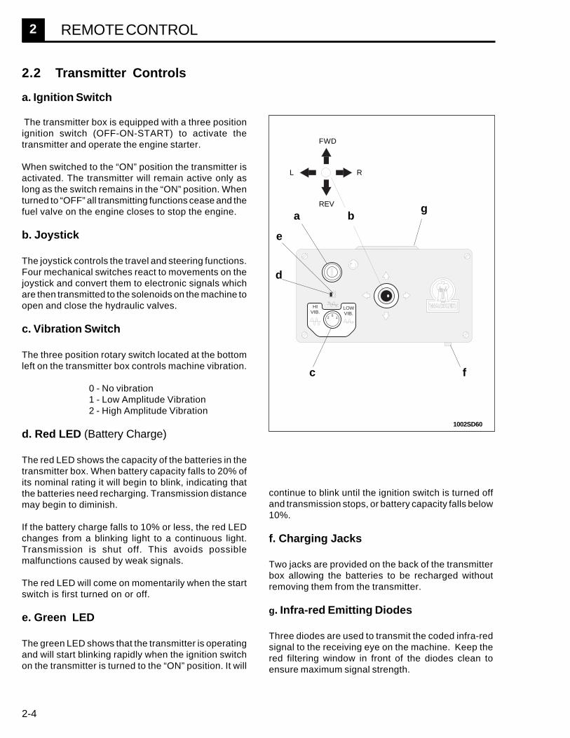
2.2 Transmitter Controls
a. Ignition Switch
The transmitter box is equipped with a three positionignition switch (OFF-ON-START) to activate thetransmitter and operate the engine starter.
When switched to the “ON” position the transmitter isactivated. The transmitter will remain active only aslong as the switch remains in the “ON” position. Whenturned to “OFF” all transmitting functions cease and thefuel valve on the engine closes to stop the engine.
b. Joystick
The joystick controls the travel and steering functions.Four mechanical switches react to movements on thejoystick and convert them to electronic signals whichare then transmitted to the solenoids on the machine toopen and close the hydraulic valves.
c. Vibration Switch
The three position rotary switch located at the bottomleft on the transmitter box controls machine vibration.
0 - No vibration1 - Low Amplitude Vibration2 - High Amplitude Vibration
d. Red LED (Battery Charge)
The red LED shows the capacity of the batteries in thetransmitter box. When battery capacity falls to 20% ofits nominal rating it will begin to blink, indicating thatthe batteries need recharging. Transmission distancemay begin to diminish.
If the battery charge falls to 10% or less, the red LEDchanges from a blinking light to a continuous light.Transmission is shut off. This avoids possiblemalfunctions caused by weak signals.
The red LED will come on momentarily when the startswitch is first turned on or off.
e. Green LED
The green LED shows that the transmitter is operatingand will start blinking rapidly when the ignition switchon the transmitter is turned to the “ON” position. It will
HIVIB.
LOWVIB.
2 10
g
c f
e
d
L
a b
R
REV
FWD
continue to blink until the ignition switch is turned offand transmission stops, or battery capacity falls below10%.
f. Charging Jacks
Two jacks are provided on the back of the transmitterbox allowing the batteries to be recharged withoutremoving them from the transmitter.
g. Infra-red Emitting Diodes
Three diodes are used to transmit the coded infra-redsignal to the receiving eye on the machine. Keep thered filtering window in front of the diodes clean toensure maximum signal strength.
1002SD60

2
2-5
REMOTE CONTROL
HOUR
REMOTE
CORD
h
CORDCONTROL
i
REMOTECONTROL
2.5 Stopping Engine and ShuttingOff Remote Control
1. Turn ignition switch on transmitter to “OFF”. Theblinking green LED will go off and the fuel valve on theengine will close. The machine will continue running for5-10 seconds until the fuel remaining in the fuel line isused up.
2. Set the selector switch on the machine to “CORDCONTROL”. The blinking red light will go out, indicatingthat the remote control system is off.
Note: If the remote control selector switch is notreturned to "CORD CONTROL" the remote controlsystem on the machine remains active and will drain thebattery on the machine.
2.3 Remote Control SelectorSwitch
The Remote Control Selector Switch (h) sets theoperating mode of the machine.
When the machine is not in use, the switch should bein the “CORD CONTROL” position. In this position theon board electronics for the remote control system aredisabled and only cord operation is possible.
In the “REMOTE CONTROL” position the remote controlsystem on the machine becomes active and will respondONLY to signals from the transmitter.
An indicator light (i) will blink when the selector switch onthe machine is switched to "REMOTE CONTROL". Thelight will continue to blink until the selector switch isreturned to “CORD CONTROL”.
2.4 Starting & Operation
1. Set the selector switch (h) on the machine to“Remote Control”.
2. Open the engine throttle control on the machine tofull speed.
3. Activate the transmitter by turning the ignition switchto “ON”. The green LED (e) on the transmitter will startto blink showing that the transmitter is operational.
Note: If the red LED on the transmitter comes on orblinks, the transmitter batteries are low and should berecharged. The machine can still be operated by turningthe transmitter off and switching to cord control.
4. Aim the transmitter in the direction of the sensingeye on the machine.
5. Start engine using ignition switch (a). Crank enginelong enough to allow oil pressure to build up. Oilpressure must reach 4 psi before fuel valve opens.
6. Leave the key in the transmitter set to“ON” whileoperating under remote control.
Keep the transmitter pointed at the receiving eye on themachine at all times to maintain contact. If thetransmitter is aimed away from the machine the fuelvalve will close and shut down the engine.
2.7 High Speed Travel
High speed travel is only available while operatingunder cord control.
2.6 Operating Range
The transmitter will remain in contact with the machineat distances up to 100 feet (30m), although at thisdistance the transmitter must be aimed more preciselyat the receiving eye on the machine. If operating intodirect sunlight or with a low battery charge the operatingrange will decrease.
1002SD61

2-6
2 REMOTE CONTROL
2.11 Charging TransmitterBatteries
The battery pack in the transmitter has enough capacityto provide 6-8 hours of continuous operation. To maintainbattery capacity, charge batteries overnight at the end ofeach working day.
To charge batteries, plug power adapter into a standard120V outlet and insert connectors into jacks provided onback of transmitter.
Approximately 12 -14 hours are required to bring thebattery up to full charge. The transmitter will operate ona partial charge; however, its operating time will bereduced accordingly. For example, charging the batteriesfor 6 hours would provide approximately 4 hours ofoperation.
The charging circuit in the transmitter is self-regulatingand limits the charging current from the power adapter to100mA.
Use the power adapter provided with the machine.
DO NOT use a quick charger to charge the batteriesinside the transmitter. These devices typically gener-ate high currents and produce heat, which may damagethe electronics inside the transmitter.
2.8 Position of Operator
Although the sensing eye on the machine can receivesignals from any direction, the joystick controller on thetransmitter is wired so that its movements correspondto the movements of the machine with the operatorstanding BEHIND the machine.
For instance, when standing behind the machine (a),pushing forward on the joystick causes the machine tomove forward (away from the operator), pushing leftwould result in the machine turning left, etc. If theoperator; however, stands in front of the machine (b) itwill respond in a direction opposite to that of thejoystick. Pushing forward on the joystick causes themachine to move toward the operator, pushing leftresults in the machine turning to the operator's right.
It is recommended that the operator follow behind themachine to avoid confusion. If the operator must changepositions, it is important that he understand the changesthat will occur in the control of the machine. a
2.9 Operating Characteristics
In an enclosed area (such as a shop floor or warehouse)or an area surrounded by large structures, the infra-redsignal may reflect off surrounding surfaces, causing itto be picked up by the machine even when the transmit-ter is pointed away from the machine. This condition ismore pronounced at shorter distances when the signalstrength is strong.
As the distance between the transmitter and machineincreases, the intensity of the signal diminishes. Thismeans that at greater distances the transmitter must beaimed more directly at the machine to maintain maxi-mum signal reception.
In some instances, especially at greater distances,objects passing between the machine and transmitter(such as support beams) will block the signal. Whenthis occurs the fuel valve will close and the engine willshut down, unless the signal can be re-establishedwithin 5-10 seconds.
2.10 Ni-cad Batteries
The batteries used to power the transmitter are highcapacity Ni-Cad cells rated at 1300 mAh and arecapable of accepting hundreds of charging cycles. Ifthe machine fails to operate for the full operating period,even after batteries have been charging overnight,batteries may need to be replaced.
CAUTION
1002SD62
b

2
2-7
REMOTE CONTROL
2.12 Setting Channel(Tuning Transmitter)
The remote control system can be tuned to 16 differentfrequencies. This allows two or more machines to operatein the same area without interference.
A channel selection switch is included in both the transmitterand the receiver on the machine. For operation of theremote control system BOTH switches must be set to theSAME channel.
To tune a transmitter to the receiver on the machine orcheck to determine which channel is selected:
1. Open the transmitter box by removing the fourscrews holding it together. Carefully lift off the topcover. The channel selector switch is located on thecircuit board inside.
2. Set the Remote Control switch on the machine to the“REMOTE CONTROL” position.
3. Turn the ignition switch on the transmitter box to“ON”.
CHANNELSELECTION
SWITCH
RECEIVERON MACHINE
TRANSMITTER
0 1 2
34
5
6789A
BC
D
E F
4. Insert a small screwdriver into the slot provided onthe channel selector switch and turn the switch until the“BAT” light on the machine goes on. The transmitter isnow tuned to the receiver.
Make note of the channel selected and label both thetransmitter and machine with the correct channel number.
2.13 Changing Channels
If a different channel than the one selected is desired, it willbe necessary to reset the selector switch in both thetransmitter and receiver. To access the selector switch inthe receiver, remove the four slotted head screws from thereceiver and lift the bottom plate off. Set the selectorswitch in both the receiver and the transmitter to the samechannel. Replace covers and label transmitter and machineto indicate new channel selection.
1002SD63

2-8
2 REMOTE CONTROL
2.14 Maintenance
All components for the remote control system are sealed and protected from moisture and vibration. Except for aperiodic visual inspection of parts and wiring, and replacement of the transmitter batteries, no other maintenanceto the system is required.
2.17 Replacing TransmitterBatteries
The battery pack inside the transmitter should bereplaced once a year or as needed. To replace batter-ies, remove the four screws holding the transmittertogether. Lift cover and carefully pull the battery con-nector from its socket.
Loosen the two small screws which secure the wires tothe connector and pull wires free. Insert the two wireleads from the new battery pack and secure them inconnector. Replace battery pack and close transmit-ter.
Be sure to observe the correct polarity when attachingbattery wire leads or the transmitter will not operate.
a
b
Note: New batteries may not be fully charged. Afterreplacing batteries charge them overnight to ensurethey are at full capacity.
2.15 Cleaning Transmitter
Although the entire circuit board is encapsulated with awater resistant material to minimize water damage,direct contact with water should be avoided.
Like any electronic device, water can quickly damagethe electronic circuits inside the transmitter. To cleanthe transmitter, wash off using a damp cloth and allowto dry.
Store the transmitter inside in a clean, dry area whenthe machine is not in use.
DO NOT immerse transmitter in water or rinse using ahose or pressure wash.
2.16 Pressure Washing Machine
When pressure washing machine, avoid spraying directlyin area around control panel (a) and back cover (b). Mostof the machine's electronic circuitry is located in this areaand could be damaged by a strong spray of water.
CAUTION
1002SD50

2
2-9
REMOTE CONTROL
1. Selector switch not set to "REMOTE CONTROL".2. Selector switch defective or connections loose.3. Main fuse on engine wiring harness blown.4. Machine battery dead.5. Cable connections on receiver loose.6. Plus (+) terminal on electronic relay loose or oxidized.7. Incorrect channel.8. Electronic relay faulty.9. Receiver or sensing eye faulty.
1. Transmitter battery low.2. Ignition switch defective.3. Battery connection loose.4. Transmitter defective.
TRANSMITTER NOT WORKING(Green LED off)
1. Transmitter battery charge low.2. Transmitter window dirty.3. Sensing eye dirty.4. Sensing eye defective.
TRANSMITTER WORKING BUTNO FUNCTIONS ON MACHINE
(Remote control light off)
TRANSMITTER DOES NOTHAVE ENOUGH RANGE -LESS THAN 30 FT (10 M)
TRANSMITTER AND RELAYWORKING BUT NO
FUNCTIONS OPERATE (GreenLED and remote control light on)
1. Defective switch or switches in transmitter.2. Poor switch connections in transmitter.3. Solenoid valve on machine defective.4. Poor ground on solenoid.5. Bad connection on relay terminal.6. Interface faulty.
ONE OR MORE FUNCTIONSINOPERATIVE
Refer to general Machine Troubleshooting on page 1-18.TRANSMITTER AND REMOTESYSTEM ON BUT ENGINE DOESNOT START
1. Channel selector switch in transmitter and receiver notmatched.
2. Poor cable connections on receiver.3. Receiver defective.4. Sensing eye defective.
2.18 Troubleshooting

2-10
2 REMOTE CONTROL
2.19 Relays and Engine Wiring Schematic(W/15 Amp Vibration Relay Fuse)
Wir
e
Co
lors
B -
Bla
ckG
- G
reen
L -
Blu
eP
- P
ink
R -
Red
T -
Tan
W-
Whi
teY
- Y
ello
wB
r -
Bro
wn
Gr
- G
ray
Or
- O
rang
eP
r -
Pur
ple
30 A
MP
ST
R
HV
R
LV
RV
TM
DI
RS
1R
S2
OS
2
OS
1
SB
S
FL
D
ST
M
VR
GA
LT
HV
D
LV
D
FT
D
RT
D
SR
D
SL
D
HT
D
BA
T
IN1
IN2
OU
T1
OU
T2
+12
INO
UT
+12
INO
UT
+12
INO
UT
+12
CL
BR
GG
15 A
MP
5030
TB
1 2 3 4 5 6 7 8 9 10 11 12
CON
R
W
Pr
P
B Gr
W
TY
Or
L
LOrYW
TTTGB
R
Gr
W
P
WB
GrB
RY
Y
Pr
RP
BT
L
HR
M
OIL
ENG CON
GR
GB
BW GGW
Br
Br
Br
Br
Br
P
RR
L G Br
Pr
LO
rY
TW
Gr
B
Pr
LO
rY
TW
Gr
B
BG
rW
TY
Or
LP
r
Br
WR
Br
G
Gr
YO
r
WR
L
IRI
EY
EA
MP
IRL
IRS
LEFT
RIGHT
REV
FWD
FUEL
HI VIB
LO VIB
START
- GND
D0 CORD
+ IR
D1 START
D2 LO VIB
D3 HI VIB
D4 FUEL
D5 FWD
D6 REV
D7 RIGHT
D8 LEFT
D9 LIGHT
G G
P
1002SD64
2
2-11
REMOTE CONTROL
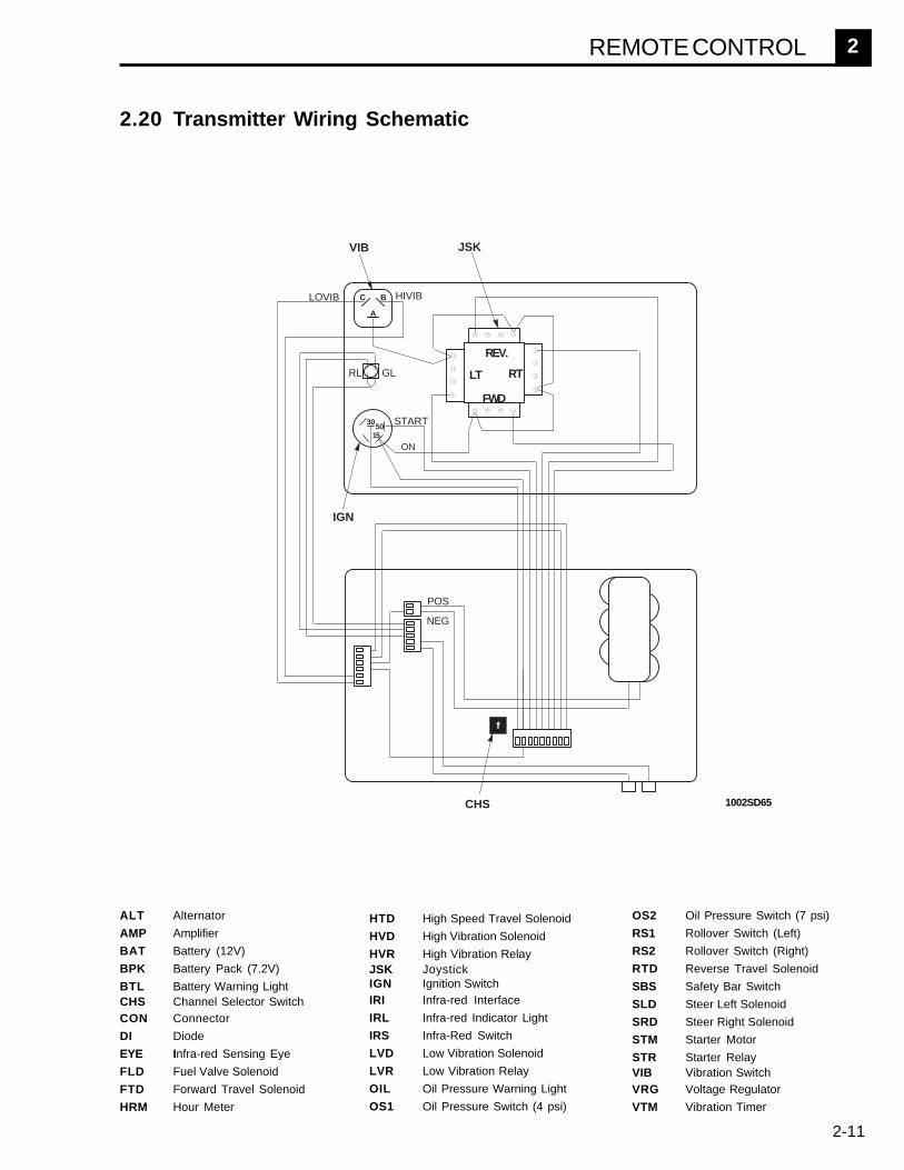
2.20 Transmitter Wiring Schematic
ALT Alternator
AMP Amplifier
BAT Battery (12V)
BPK Battery Pack (7.2V)
BTL Battery Warning LightCHS Channel Selector SwitchCON Connector
DI Diode
EYE Infra-red Sensing Eye
FLD Fuel Valve Solenoid
FTD Forward Travel Solenoid
HRM Hour Meter
HTD High Speed Travel Solenoid
HVD High Vibration Solenoid
HVR High Vibration RelayJSK JoystickIGN Ignition SwitchIRI Infra-red Interface
IRL Infra-red Indicator Light
IRS Infra-Red Switch
LVD Low Vibration Solenoid
LVR Low Vibration Relay
OIL Oil Pressure Warning Light
OS1 Oil Pressure Switch (4 psi)
OS2 Oil Pressure Switch (7 psi)
RS1 Rollover Switch (Left)
RS2 Rollover Switch (Right)
RTD Reverse Travel Solenoid
SBS Safety Bar Switch
SLD Steer Left Solenoid
SRD Steer Right Solenoid
STM Starter Motor
STR Starter RelayVIB Vibration SwitchVRG Voltage Regulator
VTM Vibration Timer
POS
NEG
START
ON
GL
BPK
CHS
RL
LOVIB HIVIB
VIB
IGN
JSK
3050
15
A
BC
REV.
FWD
LT RT
1002SD65

2-12
2 REMOTE CONTROL
2.21 Relays and Engine Wiring Schematic(W/O 15 Amp Vibration Relay Fuse)
Wir
e
Co
lors
B -
Bla
ckG
- G
reen
L -
Blu
eP
- P
ink
R -
Red
T -
Tan
W-
Whi
teY
- Y
ello
wB
r -
Bro
wn
Gr
- G
ray
Or
- O
rang
eP
r -
Pur
ple
Br
Br
R
30 A
MP
ST
R
HV
R
LV
RV
TM
DI
RS
1R
S2
OS
2
OS
1
SB
S
FL
D
ST
M
VR
GA
LT
HV
D
LV
D
FT
D
RT
D
SR
D
SL
D
HT
D
BA
T
IN1
IN2
OU
T1
OU
T2
+12
INO
UT
+12
INO
UT
+12
INO
UT
+12
CL
BR
GG
5030
TB
1 2 3 4 5 6 7 8 9 10 11 12
CON
R
W
Pr
P
B Gr
W
TY
Or
L
LOrYW
TTTGB
R
Gr
W
P
WB
GrB
RY
Y
Pr
R
R
BT
L
HR
M
OIL
ENG CON
GR
GB
BW GGW
Br
Br
Br
Br
Br
P
RR
L G Br
Pr
LO
rY
TW
Gr
B
Pr
LO
rY
TW
Gr
B
BG
rW
TY
Or
LP
r
Br
WR
Br
G
Gr
YO
r
WR
L
IRI
EY
EA
MP
IRL
IRS
LEFT
RIGHT
REV
FWD
FUEL
HI VIB
LO VIB
START
- GND
D0 CORD
+ IR
D1 START
D2 LO VIB
D3 HI VIB
D4 FUEL
D5 FWD
D6 REV
D7 RIGHT
D8 LEFT
D9 LIGHT
G G
1002SD66

Use Of Threadlockers and Sealants
Threadlocking adhesives and sealants are specified throughout this manual and should be used where indicated.Threadlocking compounds normally break down at temperatures above 350° F (175° C). If a screw or bolt is hard toremove, heat it using a small propane torch to break down sealant. When applying sealants, follow instructions oncontainer. The sealants listed below are recommended for use on WACKER equipment.
SEALANTS
TYPE( ) = Europe COLOR USAGE PART NO. - SIZE
Loctite 222 Purple Low strength, for locking threads smaller than 1/4" (6 mm). 73287 - 10 mlHernon 420 Hand tool removable.Omnifit 1150 (50M) Temp. range, -65 to 300 degrees F (-54 to 149 degrees C)
Loctite 243 Blue Medium strength, for locking threads larger than 1/4" (6 mm). 29311 - .5 mlHernon 423 Hand tool removable. 17380 - 50 mlOmnifit 1350 (100M) Temp. range, -65 to 300 degrees F (-54 to 149 degrees C)
Loctite 271 / 277 Red High strength, for all threads up to 1" (25 mm). 29312 - .5 mlHernon 427 Heat parts before disassembly. 26685 - 10 mlOmnifit 1550 (220M) Temp. range, -65 to 300 degrees F (-54 to 149 degrees C) 73285 - 50 ml
Loctite 290 Green Medium to high strength, for locking preassembled threads 28824 - .5 mlHernon 431 and for sealing weld porosity (wicking). 25316 - 10 mlOmnifit 1710 (230LL) Gaps up to 0.005" (0.13 mm)
Temp. range, -65 to 300 degrees F (-54 to 149 degrees C)
Loctite 609 Green Medium strength retaining compound for slip or press fit 29314 - .5 mlHernon 822 of shafts, bearings, gears, pulleys, etc.Omnifit 1730 (230L) Gaps up to 0.005" (0.13 mm)
Temp. range, -65 to 300 degrees F (-54 to 149 degrees C)
Loctite 545 Brown Hydraulic sealant 79356 - 50 mlHernon 947 Temp. range, -65 to 300 degrees F (-54 to 149 degrees C)Omnifit 1150 (50M)
Loctite 592 White Pipe sealant with Teflon for moderate pressures. 26695 - 6 mlHernon 920 Temp. range, -65 to 300 degrees F (-54 to 149 degrees C) 73289 - 50 mlOmnifit 790
Loctite 515 Purple Form-in-place gasket for flexible joints. 70735 - 50 mlHernon 910 Fills gaps up to 0.05" (1.3 mm)Omnifit 10 Temp. range, -65 to 300 degrees F (-54 to 149 degrees C)
Loctite 496 Clear Instant adhesive for bonding rubber, metal and plastics;Hernon 110 general purpose. 52676 - 1 oz.Omnifit Sicomet 7000 For gaps up to 0.006" (0.15 mm)
Read caution instructions before using.Temp. range, -65 to 180 degrees F (-54 to 82 degrees C)
Loctite Primer T Aerosol Fast curing primer for threadlocking, retaining and 2006124 - 6 oz.Hernon Primer 10 Spray sealing compounds. Must be used with stainless steelOmnifit VC Activator hardware. Recommended for use with gasket sealants.
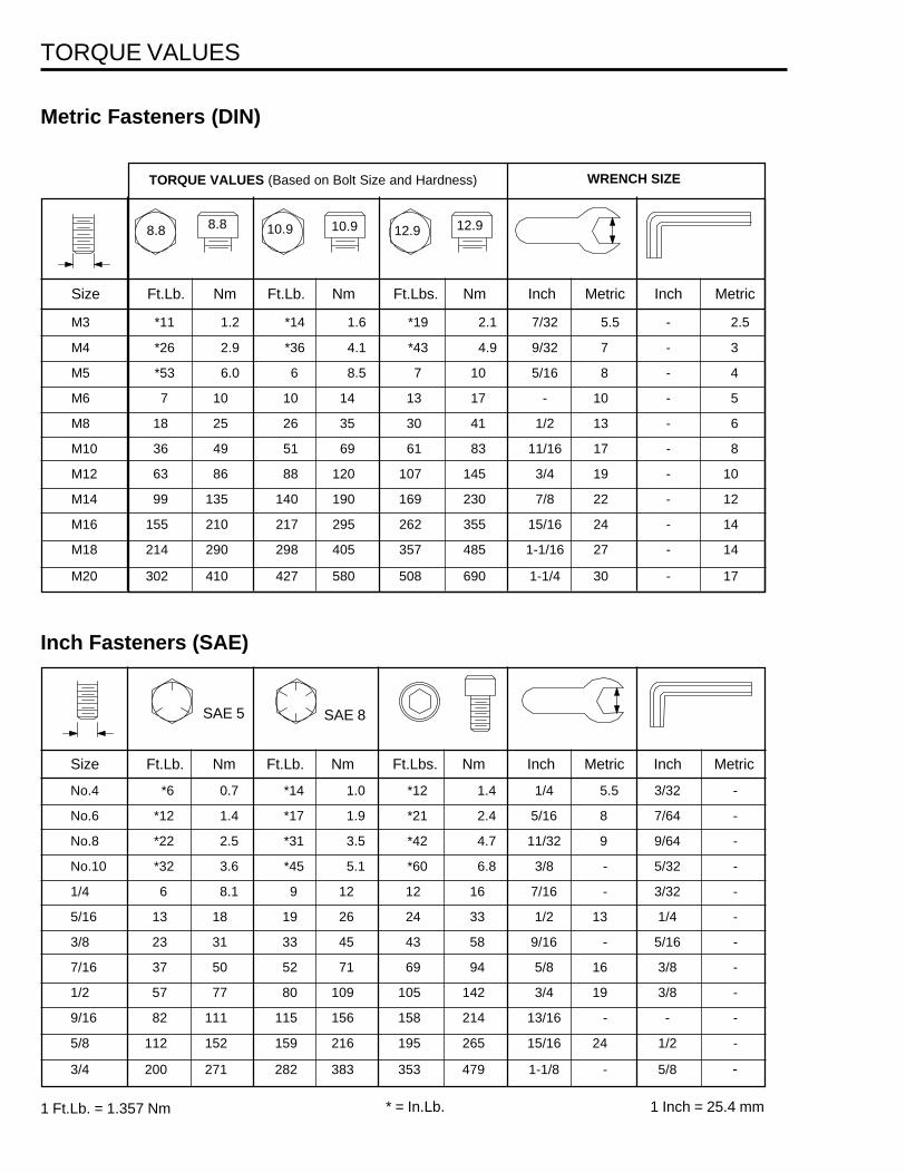
Size Ft.Lb. Nm Ft.Lb. Nm Ft.Lbs. Nm Inch Metric Inch Metric
No.4 *6 0.7 *14 1.0 *12 1.4 1/4 5.5 3/32 -
No.6 *12 1.4 *17 1.9 *21 2.4 5/16 8 7/64 -
No.8 *22 2.5 *31 3.5 *42 4.7 11/32 9 9/64 -
No.10 *32 3.6 *45 5.1 *60 6.8 3/8 - 5/32 -
1/4 6 8.1 9 12 12 16 7/16 - 3/32 -
5/16 13 18 19 26 24 33 1/2 13 1/4 -
3/8 23 31 33 45 43 58 9/16 - 5/16 -
7/16 37 50 52 71 69 94 5/8 16 3/8 -
1/2 57 77 80 109 105 142 3/4 19 3/8 -
9/16 82 111 115 156 158 214 13/16 - - -
5/8 112 152 159 216 195 265 15/16 24 1/2 -
3/4 200 271 282 383 353 479 1-1/8 - 5/8 -
1 Ft.Lb. = 1.357 Nm 1 Inch = 25.4 mm* = In.Lb.
Metric Fasteners (DIN)
Inch Fasteners (SAE)
Size Ft.Lb. Nm Ft.Lb. Nm Ft.Lbs. Nm Inch Metric Inch Metric
M3 *11 1.2 *14 1.6 *19 2.1 7/32 5.5 - 2.5
M4 *26 2.9 *36 4.1 *43 4.9 9/32 7 - 3
M5 *53 6.0 6 8.5 7 10 5/16 8 - 4
M6 7 10 10 14 13 17 - 10 - 5
M8 18 25 26 35 30 41 1/2 13 - 6
M10 36 49 51 69 61 83 11/16 17 - 8
M12 63 86 88 120 107 145 3/4 19 - 10
M14 99 135 140 190 169 230 7/8 22 - 12
M16 155 210 217 295 262 355 15/16 24 - 14
M18 214 290 298 405 357 485 1-1/16 27 - 14
M20 302 410 427 580 508 690 1-1/4 30 - 17
8.8 10.9
TORQUE VALUES (Based on Bolt Size and Hardness) WRENCH SIZE
12.9 12.910.98.8
TORQUE VALUES
SAE 5 SAE 8