Embed Size (px)
Citation preview
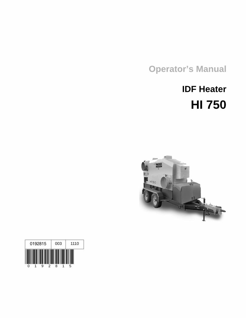
0192815 003 1110
0 1 9 2 8 1 5
Operator’s Manual
IDF Heater
HI 750
Copyright notice
© Copyright 2010 by Wacker Neuson Corporation.All rights, including copying and distribution rights, are reserved.This publication may be photocopied by the original purchaser of the machine. Any other type of reproduction is prohibited without express written permission from Wacker Neuson Corporation.Any type of reproduction or distribution not authorized by Wacker Neuson Corporation represents an infringement of valid copyrights. Violators will be prosecuted.
Trademarks All trademarks referenced in this manual are the property of their respective owners.
Manufacturer Wacker Neuson CorporationN92W15000 Anthony AvenueMenomonee Falls, WI 53051 U.S.A.Tel: (262) 255-0500 · Fax: (262) 255-0550 · Tel: (800) 770-0957www.wackerneuson.com
Original instructions
This Operator’s Manual presents the original instructions. The original language of this Operator’s Manual is American English.
HI 750 Foreword
ForewordMachines covered by this manualThis manual covers machines with the following item numbers:
Machine documentation
Keep a copy of the Operator’s Manual with the machine at all times. Use the separate Parts Book supplied with the machine to order replacement parts. Refer to the separate Repair Manual for detailed instructions on servicing and repairing the machine.If you are missing any of these documents, please contact Wacker Neuson Corporation to order a replacement or visit www.wackerneuson.com. When ordering parts or requesting service information, be prepared to provide the machine model number, item number, revision number, and serial number.
Expectations for information in this manual
This manual provides information and procedures to safely operate and maintain the above Wacker Neuson model(s). For your own safety and to reduce the risk of injury, carefully read, understand, and observe all instructions described in this manual. Wacker Neuson Corporation expressly reserves the right to make technical modifications, even without notice, which improve the performance or safety standards of its machines.The information contained in this manual is based on machines manufactured up until the time of publication. Wacker Neuson Corporation reserves the right to change any portion of this information without notice.
CALIFORNIA Proposition 65 Warning
Engine exhaust, some of its constituents, and certain vehicle components, contain or emit chemicals known to the State of California to cause cancer and birth defects or other reproductive harm.
Laws pertaining to spark arresters
NOTICE: State Health Safety Codes and Public Resources Codes specify that in certain locations spark arresters be used on internal combustion engines that use hydrocarbon fuels. A spark arrester is a device designed to prevent accidental discharge of sparks or flames from the engine exhaust. Spark arresters are qualified and rated by the United States Forest Service for this purpose. In order to comply with local laws regarding spark arresters, consult the engine distributor or the local Health and Safety Administrator.
Machine Item NumberHI 750 D 0620856, 0620923, 0620924HI 750 G 0620857, 0620928, 0620929HI 750 DM 0620930HI 750 DGM 0620859
ghi_tx001257gb.fm 3
Foreword HI 750
Manufacturer’s approvalThis manual contains references to approved parts, attachments, and modifications. The following definitions apply:
Approved parts or attachments are those either manufactured or provided by Wacker Neuson. Approved modifications are those performed by an authorized Wacker Neuson service center according to written instructions published by Wacker Neuson.Unapproved parts, attachments, and modifications are those that do not meet the approved criteria.
Unapproved parts, attachments, or modifications may have the following consequences:
Serious injury hazards to the operator and persons in the work areaPermanent damage to the machine which will not be covered under warranty
Contact your Wacker Neuson dealer immediately if you have questions about approved or unapproved parts, attachments, or modifications.
4 ghi_tx001257gb.fm
Table of ContentsHI 750
Foreword 3
1 Safety Information 9
1.1 Signal Words Used in this Manual ....................................................... 91.2 Machine Description and Intended Use ............................................. 101.3 Safety Guidelines for Operating the Machine ..................................... 111.4 Safety Guidelines While Using Combustion Burners ......................... 121.5 Service Safety .................................................................................... 13
2 Labels 15
2.1 Label Locations .................................................................................. 152.2 Label Meanings .................................................................................. 16
3 Lifting and Transporting 22
3.1 Lifting the Machine ............................................................................. 223.2 Towing Safety ..................................................................................... 243.3 Transporting the Machine on a Flat Bed ............................................ 26
4 Operation 29
4.1 Preparing the Machine for First Use ................................................... 294.2 Recommended Fuel ........................................................................... 294.3 Features and Controls ........................................................................ 304.4 Control Panel ...................................................................................... 314.5 Positioning the Machine ..................................................................... 324.6 Before Starting ................................................................................... 334.7 Installing the Remote Thermostat ...................................................... 344.8 Starting the Generator (if equipped) ................................................... 344.9 Starting ............................................................................................... 354.10 Monitoring the Operating Parameters ................................................ 364.11 Stopping ............................................................................................. 364.12 Emergency Shutdown Procedure ....................................................... 374.13 Operating at High Elevations .............................................................. 384.14 Adjusting the Air Output Volume ........................................................ 394.15 Adjusting the CFM .............................................................................. 40
wc_bo0179826en_001TOC.fm 5
Table of ContentsHI 750
5 Factory-Installed Options 42
5.1 Variable Frequency Drive (VFD) .........................................................425.2 Trailer ..................................................................................................425.3 Generator ............................................................................................435.4 Diesel Burner .......................................................................................435.5 Natural Gas (NG)/Liquid Propane (LP) Burner ....................................43
6 Accessories 44
6.1 Available Accessories .........................................................................446.2 Installing the Heater Duct ....................................................................446.3 Installing the Remote Thermostat .......................................................45
7 Burner Setup—Oil 46
7.1 Factory Settings ..................................................................................467.2 Setting up the Burner ..........................................................................467.3 Setting/Checking the Electrodes .........................................................497.4 Setting the “Z” Distance .......................................................................517.5 Adjusting the Air Settings ....................................................................537.6 Adjusting the Fuel Pressure—Oil Burner ............................................54
8 Burner Setup—Gas 55
8.1 Factory Settings ..................................................................................558.2 Setting up the Burner ..........................................................................568.3 Adjusting the Ionization Probe and the Electrode ...............................588.4 Checking the Burner Orifice ................................................................598.5 Checking the Burner Air Damper Setting ............................................618.6 Checking the Supply Gas Pressure ....................................................628.7 Checking and Adjusting the Burner Gas Pressure ..............................648.8 Changing the Burner Type (Oil to NG or LP) ......................................668.9 Changing the Burner Orifice From Natural Gas to LP .........................678.10 Changing the Gas Burner Regulator Spring ........................................69
9 Maintenance 70
9.1 Periodic Maintenance Schedule ..........................................................709.2 Replacing the Burner Nozzle ...............................................................719.3 Replacing the Blower Belt ...................................................................749.4 Bleeding Air from the Generator Fuel System (if equipped) ................769.5 General Cleaning Guidelines ..............................................................77
6 wc_bo0179826en_001TOC.fm
Table of ContentsHI 750
10 Basic Troubleshooting 78
11 Technical Data 80
11.1 Machine .............................................................................................. 80
12 Schematics 83
12.1 HI 750 with VFD—Electrical Schematic ............................................. 8312.2 HI 750 with VFD—Electrical Schematic Components ........................ 8412.3 HI 750, no VFD—Electrical Schematic ............................................... 8512.4 HI 750, no VFD—Electrical Schematic Components ......................... 86
wc_bo0179826en_001TOC.fm 7
Safety Information HI 750
1 Safety Information1.1 Signal Words Used in this ManualThis manual contains DANGER, WARNING, CAUTION, NOTICE, and NOTE signal words which must be followed to reduce the possibility of personal injury, damage to the equipment, or improper service.
NOTICE: Used without the safety alert symbol, NOTICE indicates a situation which, if not avoided, could result in property damage.
Note: A Note contains additional information important to a procedure.
This is the safety alert symbol. It is used to alert you to potential personal hazards.Obey all safety messages that follow this symbol.
DANGERDANGER indicates a hazardous situation which, if not avoided, will result in death or serious injury.
To avoid death or serious injury from this type of hazard, obey all safety messages that follow this signal word.
WARNINGWARNING indicates a hazardous situation which, if not avoided, could result in death or serious injury.
To avoid possible death or serious injury from this type of hazard, obey all safety messages that follow this signal word.
CAUTION! CAUTION indicates a hazardous situation which, if not avoided, could result in minor or moderate injury.
To avoid possible minor or moderate injury from this type of hazard, obey all safety messages that follow this signal word.
8 ghi_si000355gb.fm
HI 750 Safety Information
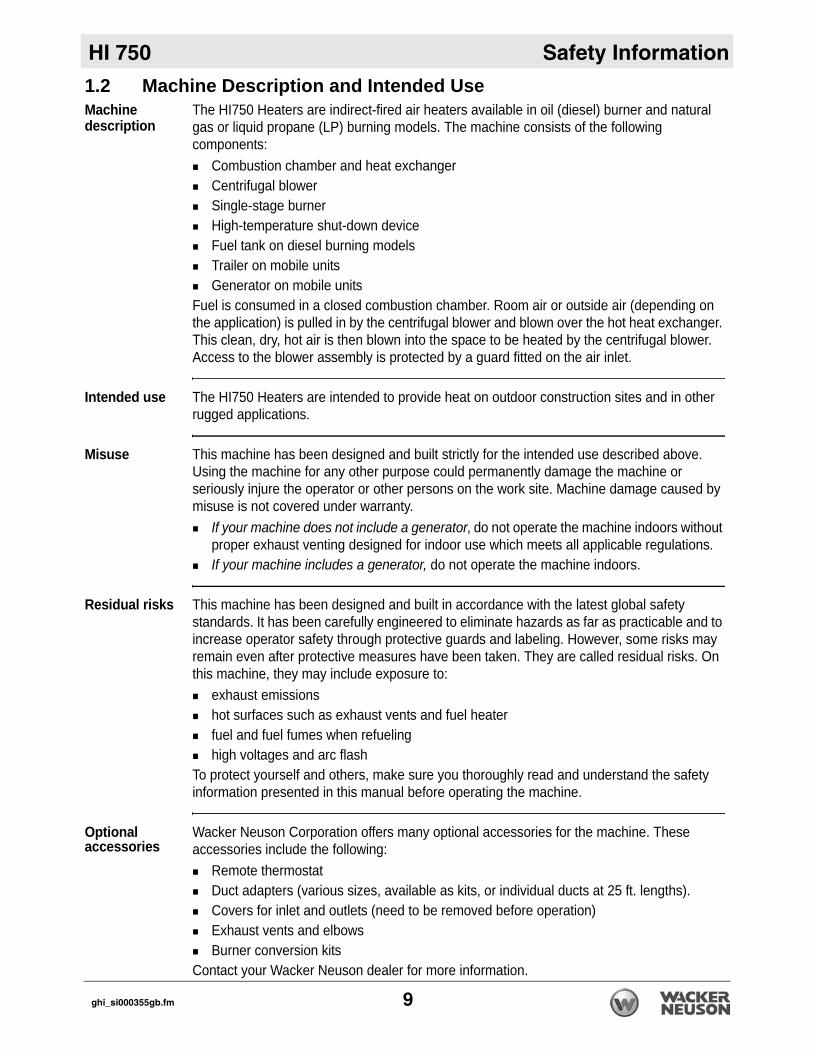
1.2 Machine Description and Intended UseMachine descriptionThe HI750 Heaters are indirect-fired air heaters available in oil (diesel) burner and natural gas or liquid propane (LP) burning models. The machine consists of the following components:
Combustion chamber and heat exchangerCentrifugal blowerSingle-stage burnerHigh-temperature shut-down deviceFuel tank on diesel burning modelsTrailer on mobile unitsGenerator on mobile units
Fuel is consumed in a closed combustion chamber. Room air or outside air (depending on the application) is pulled in by the centrifugal blower and blown over the hot heat exchanger. This clean, dry, hot air is then blown into the space to be heated by the centrifugal blower. Access to the blower assembly is protected by a guard fitted on the air inlet.
Intended use The HI750 Heaters are intended to provide heat on outdoor construction sites and in other rugged applications.
Misuse This machine has been designed and built strictly for the intended use described above. Using the machine for any other purpose could permanently damage the machine or seriously injure the operator or other persons on the work site. Machine damage caused by misuse is not covered under warranty.
If your machine does not include a generator, do not operate the machine indoors without proper exhaust venting designed for indoor use which meets all applicable regulations. If your machine includes a generator, do not operate the machine indoors.
Residual risks This machine has been designed and built in accordance with the latest global safety standards. It has been carefully engineered to eliminate hazards as far as practicable and to increase operator safety through protective guards and labeling. However, some risks may remain even after protective measures have been taken. They are called residual risks. On this machine, they may include exposure to:
exhaust emissionshot surfaces such as exhaust vents and fuel heaterfuel and fuel fumes when refuelinghigh voltages and arc flash
To protect yourself and others, make sure you thoroughly read and understand the safety information presented in this manual before operating the machine.
Optional accessories
Wacker Neuson Corporation offers many optional accessories for the machine. These accessories include the following:
Remote thermostatDuct adapters (various sizes, available as kits, or individual ducts at 25 ft. lengths). Covers for inlet and outlets (need to be removed before operation)Exhaust vents and elbowsBurner conversion kits
Contact your Wacker Neuson dealer for more information.
ghi_si000355gb.fm 9
Safety Information HI 750
1.3 Operating SafetyOperator trainingBefore operating the machine:Read and understand the operating instructions contained in all manuals delivered with the machine.Familiarize yourself with the location and proper use of all controls and safety devices. Contact Wacker Neuson Corporation for additional training if necessary.
When operating this machine:Do not allow improperly trained people to operate the machine. People operating the machine must be familiar with the potential risks and hazards associated with it.
Machine condition
Only operate the machine when:The Heat Exchanger is in proper working order.All safety devices and guards are in place and in working order.All controls operate correctly.The machine is set up correctly according to the instructions in the Operator’s Manual.The machine is clean.The machine’s labels are legible.
When operating the machine:Do not modify or defeat the safety devices.Do not use worn electrical cords.Do not use faulty fuel supplies.
Heat exchanger inspection
The heat exchanger must be checked annually before each heating season to ensure it is in good working order. Shorter inspection intervals are recommended for units operating under extreme transportation or operating conditions.
Guidelines for operator
When operating the machine:Remain aware of the machine’s moving parts. Keep hands, feet, and loose clothing away from the machine’s moving parts.Wear protective clothing appropriate to the job site when operating the machine.Wear safety glasses.
When operating the machine:Do not operate a machine in need of repair.Do not smoke near the machine.
Personal Protective Equipment (PPE)
Wear the following Personal Protective Equipment (PPE) while operating this machine:
Close-fitting work clothes that do not hinder movementSafety glasses with side shieldsHearing protectionSafety-toed footwear
10 ghi_si000355gb.fm
HI 750 Safety Information
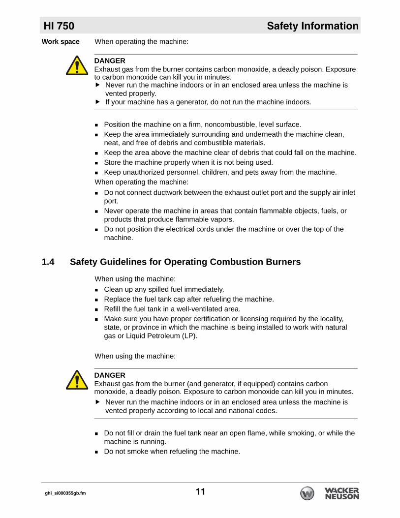
Work space When operating the machine:Position the machine on a firm, noncombustible, level surface.Keep the area immediately surrounding and underneath the machine clean, neat, and free of debris and combustible materials.Keep the area above the machine clear of debris that could fall on the machine.Store the machine properly when it is not being used. Keep unauthorized personnel, children, and pets away from the machine.
When operating the machine:Do not connect ductwork between the exhaust outlet port and the supply air inlet port.Never operate the machine in areas that contain flammable objects, fuels, or products that produce flammable vapors.Do not position the electrical cords under the machine or over the top of the machine.
1.4 Safety Guidelines for Operating Combustion Burners
When using the machine:Clean up any spilled fuel immediately.Replace the fuel tank cap after refueling the machine.Refill the fuel tank in a well-ventilated area.Make sure you have proper certification or licensing required by the locality, state, or province in which the machine is being installed to work with natural gas or Liquid Petroleum (LP).
When using the machine:
Do not fill or drain the fuel tank near an open flame, while smoking, or while the machine is running.Do not smoke when refueling the machine.
DANGERExhaust gas from the burner contains carbon monoxide, a deadly poison. Exposure to carbon monoxide can kill you in minutes.
Never run the machine indoors or in an enclosed area unless the machine is vented properly. If your machine has a generator, do not run the machine indoors.
DANGERExhaust gas from the burner (and generator, if equipped) contains carbon monoxide, a deadly poison. Exposure to carbon monoxide can kill you in minutes.
Never run the machine indoors or in an enclosed area unless the machine is vented properly according to local and national codes.
ghi_si000355gb.fm 11
Safety Information HI 750
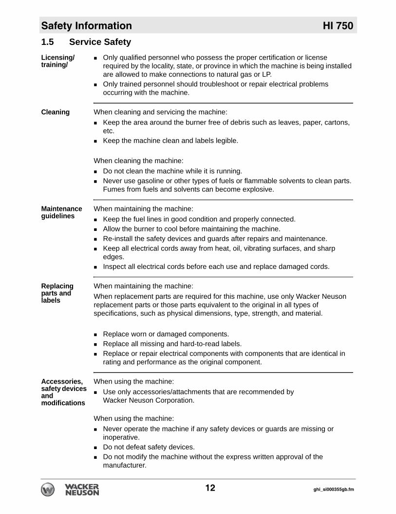
1.5 Service SafetyLicensing/training/Only qualified personnel who possess the proper certification or license required by the locality, state, or province in which the machine is being installed are allowed to make connections to natural gas or LP.Only trained personnel should troubleshoot or repair electrical problems occurring with the machine.
Cleaning When cleaning and servicing the machine:Keep the area around the burner free of debris such as leaves, paper, cartons, etc.Keep the machine clean and labels legible.
When cleaning the machine:Do not clean the machine while it is running.Never use gasoline or other types of fuels or flammable solvents to clean parts. Fumes from fuels and solvents can become explosive.
Maintenance guidelines
When maintaining the machine:Keep the fuel lines in good condition and properly connected. Allow the burner to cool before maintaining the machine.Re-install the safety devices and guards after repairs and maintenance.Keep all electrical cords away from heat, oil, vibrating surfaces, and sharp edges. Inspect all electrical cords before each use and replace damaged cords.
Replacing parts and labels
When maintaining the machine:When replacement parts are required for this machine, use only Wacker Neuson replacement parts or those parts equivalent to the original in all types of specifications, such as physical dimensions, type, strength, and material.
Replace worn or damaged components.Replace all missing and hard-to-read labels.Replace or repair electrical components with components that are identical in rating and performance as the original component.
Accessories, safety devices and modifications
When using the machine:Use only accessories/attachments that are recommended by Wacker Neuson Corporation.
When using the machine:Never operate the machine if any safety devices or guards are missing or inoperative.Do not defeat safety devices. Do not modify the machine without the express written approval of the manufacturer.
12 ghi_si000355gb.fm
HI 750 Safety Information
Personal Protective Equipment (PPE)Wear the following Personal Protective Equipment (PPE) while servicing or maintaining this machine:
Close-fitting work clothes that do not hinder movementSafety glasses with side shieldsHearing protectionSafety-toed footwear
In addition, before servicing or maintaining the machine:Tie back long hair.Remove all jewelry (including rings).
ghi_si000355gb.fm 13
Labels HI 750
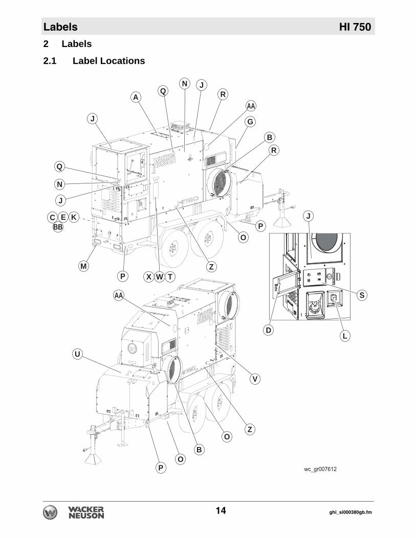
2 Labels2.1 Label Locations
P
U
AA
B
P
Z
V
J
Q
J
J
M
A
WX T
BBC E K
NQ
J
DL
S
N
R
B
G
R
AA
PO
Z
O
O
14 ghi_si000380gb.fm
HI 750 Labels
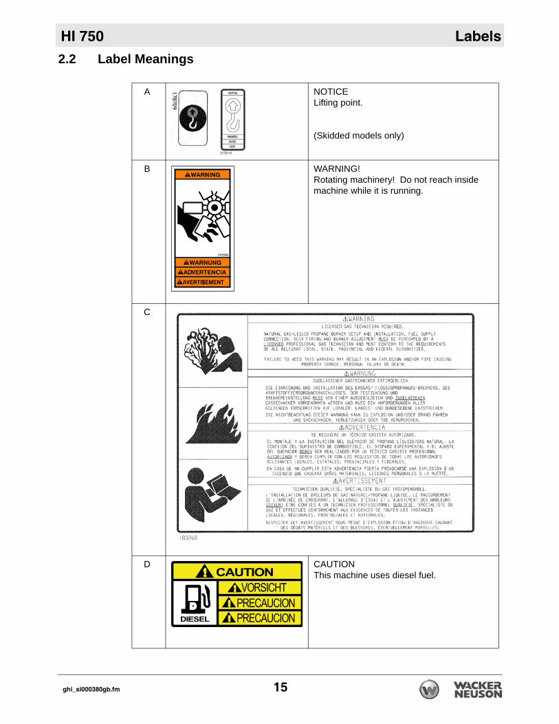
2.2 Label MeaningsA NOTICELifting point.
(Skidded models only)
B WARNING! Rotating machinery! Do not reach inside machine while it is running.
C
D CAUTIONThis machine uses diesel fuel.
ghi_si000380gb.fm 15
Labels HI 750
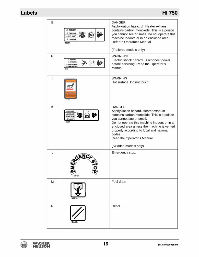
E DANGERAsphyxiation hazazrd. Heater exhaust contains carbon monoxide. This is a poison you cannot see or smell. Do not operate this machine indoors or in an enclosed area. Refer to Operator's Manual.
(Trailered models only)
G WARNING!Electric shock hazard. Disconnect power before servicing. Read the Operator’s Manual.
J WARNINGHot surface. Do not touch.
K DANGERAsphyxiation hazard. Heater exhaust contains carbon monoxide. This is a poison you cannot see or smell.Do not operate this machine indoors or in an enclosed area unless the machine is vented properly according to local and national codes.Read the Operator’s Manual.
(Skidded models only)
L Emergency stop.
M Fuel drain
N Reset
16 ghi_si000380gb.fm
HI 750 Labels
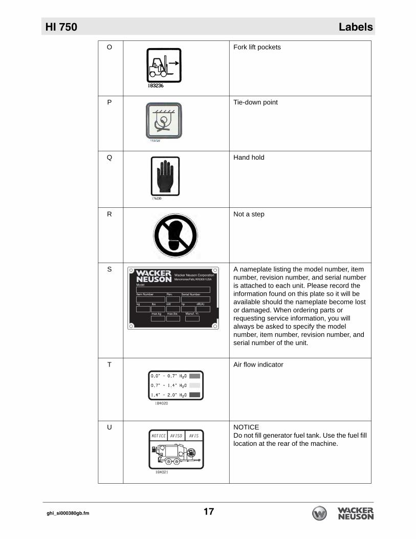
O Fork lift pockets
P Tie-down point
Q Hand hold
R Not a step
S A nameplate listing the model number, item number, revision number, and serial number is attached to each unit. Please record the information found on this plate so it will be available should the nameplate become lost or damaged. When ordering parts or requesting service information, you will always be asked to specify the model number, item number, revision number, and serial number of the unit.
T Air flow indicator
U NOTICEDo not fill generator fuel tank. Use the fuel fill location at the rear of the machine.
ghi_si000380gb.fm 17
Labels HI 750
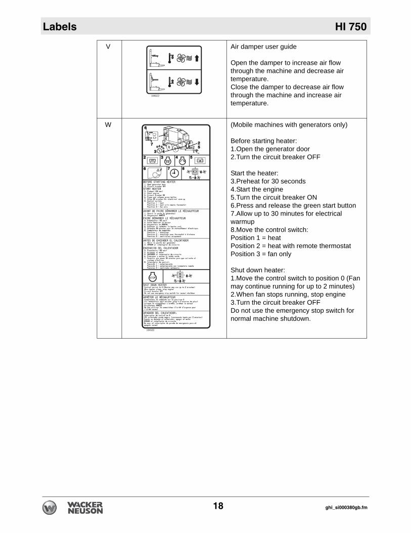
V Air damper user guide
Open the damper to increase air flow through the machine and decrease air temperature.Close the damper to decrease air flow through the machine and increase air temperature.
W (Mobile machines with generators only)
Before starting heater:1.Open the generator door2.Turn the circuit breaker OFF
Start the heater:3.Preheat for 30 seconds4.Start the engine5.Turn the circuit breaker ON6.Press and release the green start button7.Allow up to 30 minutes for electrical warmup8.Move the control switch: Position 1 = heatPosition 2 = heat with remote thermostatPosition 3 = fan only
Shut down heater:1.Move the control switch to position 0 (Fan may continue running for up to 2 minutes)2.When fan stops running, stop engine3.Turn the circuit breaker OFFDo not use the emergency stop switch for normal machine shutdown.
18 ghi_si000380gb.fm
HI 750 Labels
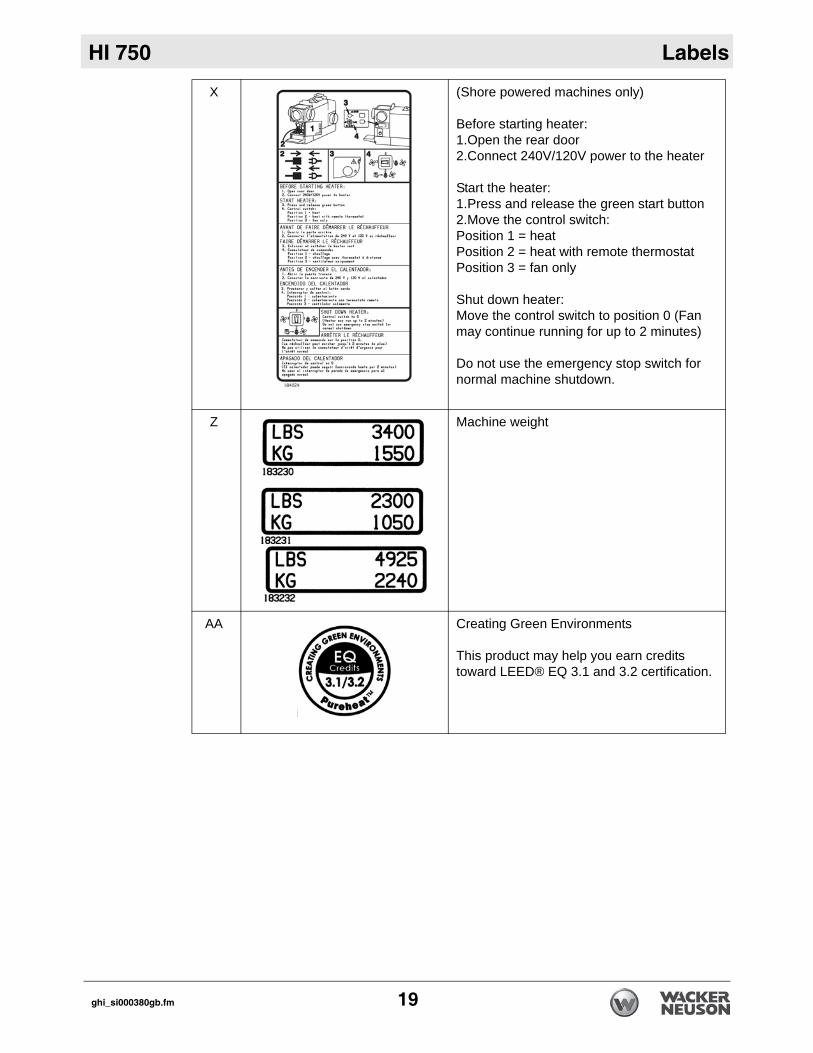
X (Shore powered machines only)
Before starting heater:1.Open the rear door2.Connect 240V/120V power to the heater
Start the heater:1.Press and release the green start button2.Move the control switch: Position 1 = heatPosition 2 = heat with remote thermostatPosition 3 = fan only
Shut down heater:Move the control switch to position 0 (Fan may continue running for up to 2 minutes)
Do not use the emergency stop switch for normal machine shutdown.
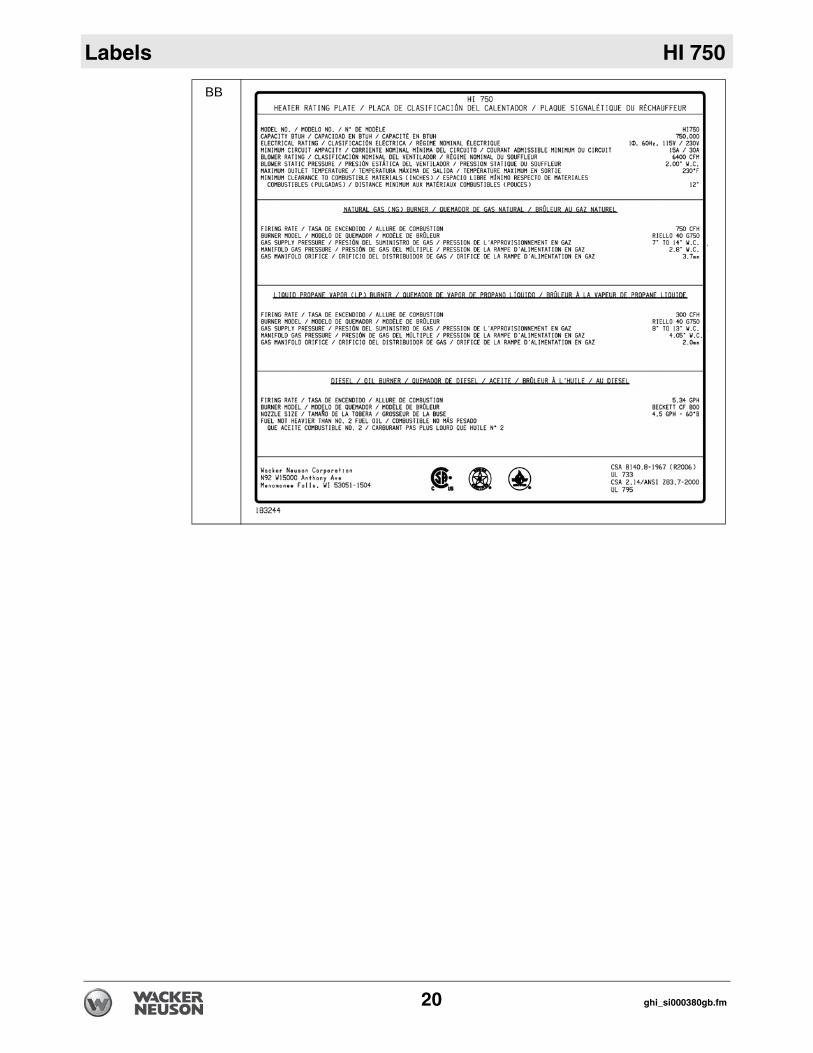
Z Machine weight
AA Creating Green Environments
This product may help you earn credits toward LEED® EQ 3.1 and 3.2 certification.
ghi_si000380gb.fm 19
Labels HI 750
BB
20 ghi_si000380gb.fm
HI 750 Lifting and Transporting
3 Lifting and Transporting3.1 Lifting the Machine
Prerequisites Properly rated lifting equipment (crane or hoist). See Chapter Technical Data.Machine stopped. See topic Stopping the Machine. All doors and access covers closed and secured.
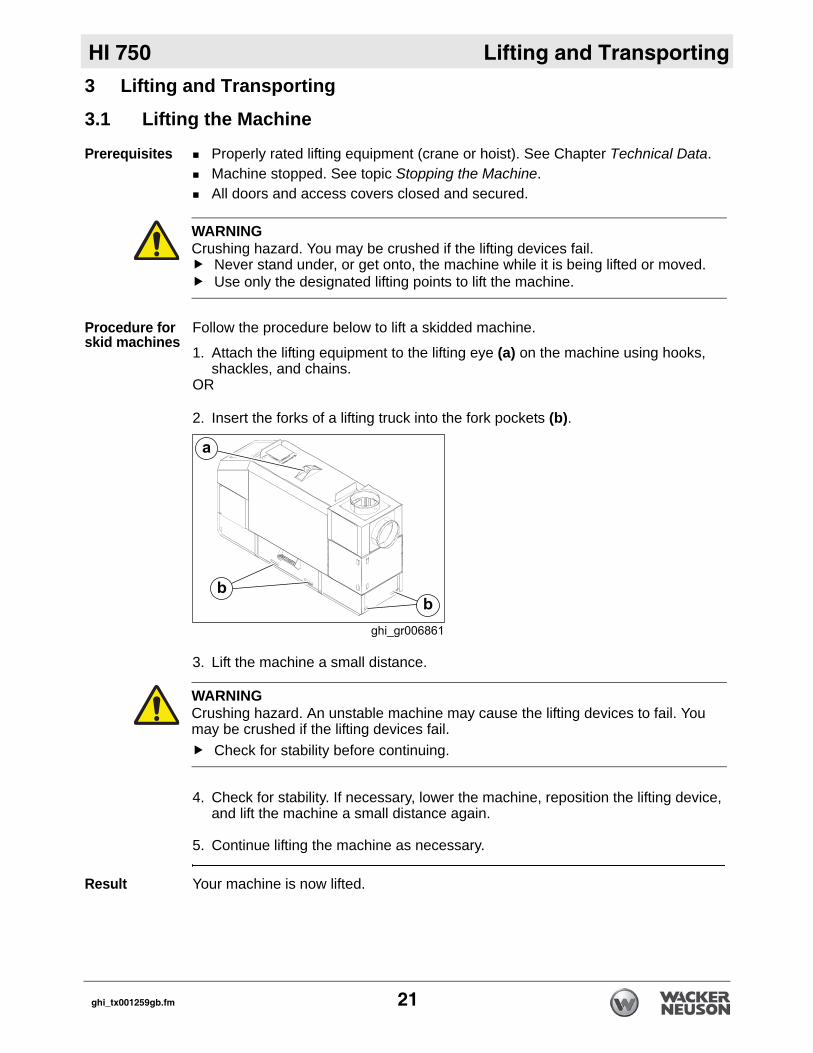
Procedure for skid machines
Follow the procedure below to lift a skidded machine.
1. Attach the lifting equipment to the lifting eye (a) on the machine using hooks, shackles, and chains.
OR
2. Insert the forks of a lifting truck into the fork pockets (b).
3. Lift the machine a small distance.
4. Check for stability. If necessary, lower the machine, reposition the lifting device, and lift the machine a small distance again.
5. Continue lifting the machine as necessary.
Result Your machine is now lifted.
WARNINGCrushing hazard. You may be crushed if the lifting devices fail.
Never stand under, or get onto, the machine while it is being lifted or moved.Use only the designated lifting points to lift the machine.
WARNINGCrushing hazard. An unstable machine may cause the lifting devices to fail. You may be crushed if the lifting devices fail.
Check for stability before continuing.
ghi_tx001259gb.fm 21
Lifting and Transporting HI 750
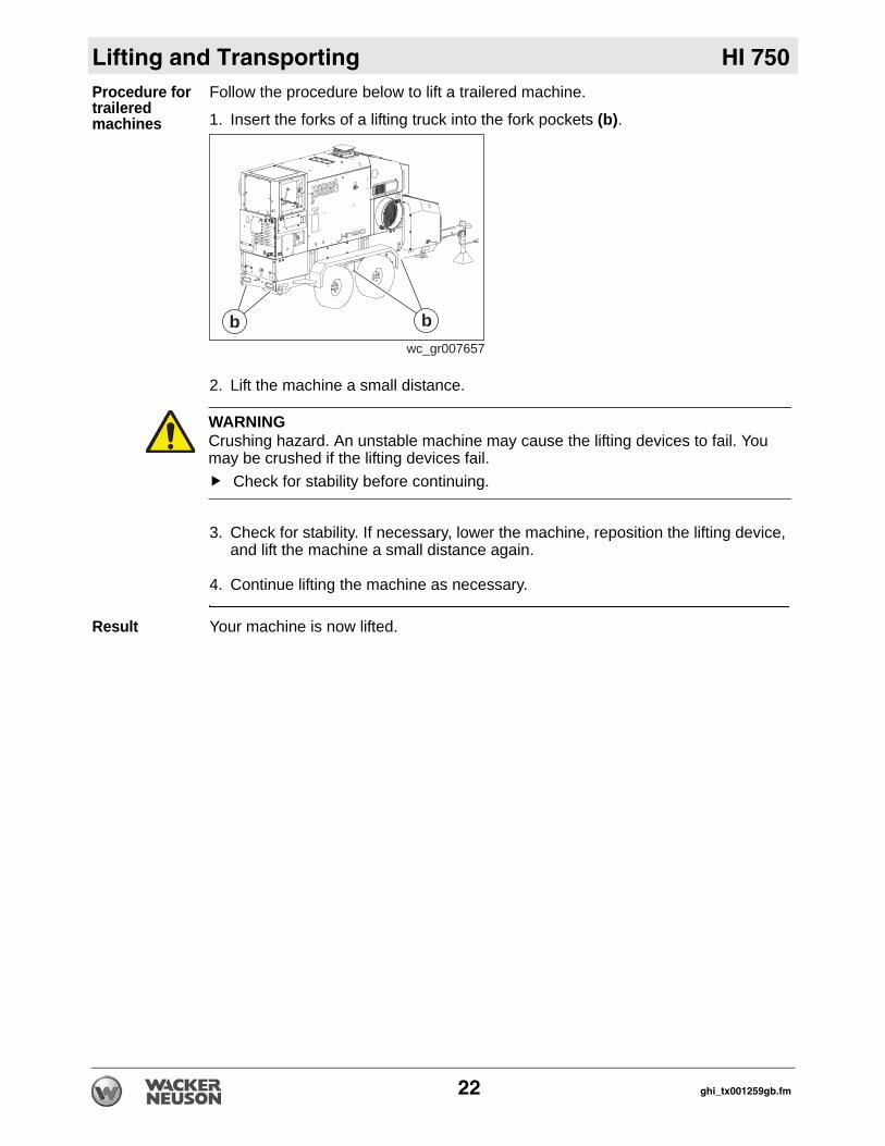
Procedure for trailered machinesFollow the procedure below to lift a trailered machine.
1. Insert the forks of a lifting truck into the fork pockets (b).
2. Lift the machine a small distance.
3. Check for stability. If necessary, lower the machine, reposition the lifting device, and lift the machine a small distance again.
4. Continue lifting the machine as necessary.
Result Your machine is now lifted.
wc_gr007657
bb
WARNINGCrushing hazard. An unstable machine may cause the lifting devices to fail. You may be crushed if the lifting devices fail.
Check for stability before continuing.
22 ghi_tx001259gb.fm
HI 750 Lifting and Transporting
3.2 Towing Safety.
Provided equipment
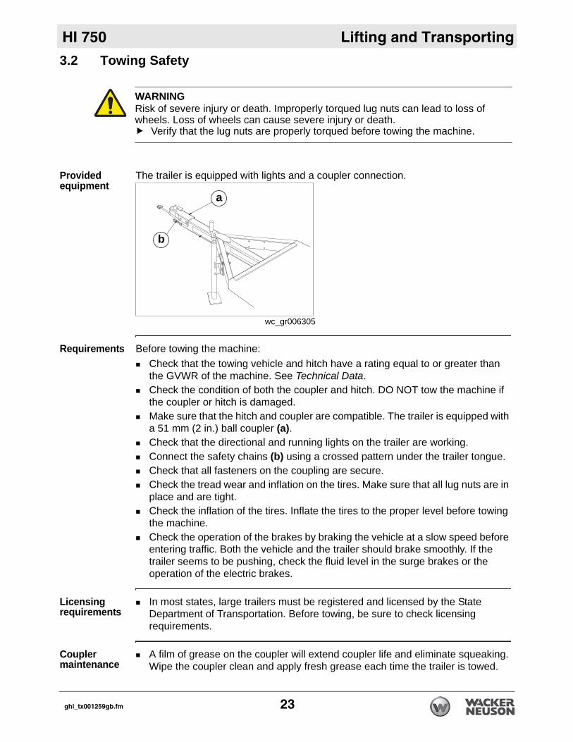
The trailer is equipped with lights and a coupler connection.
Requirements Before towing the machine:Check that the towing vehicle and hitch have a rating equal to or greater than the GVWR of the machine. See Technical Data.Check the condition of both the coupler and hitch. DO NOT tow the machine if the coupler or hitch is damaged.Make sure that the hitch and coupler are compatible. The trailer is equipped with a 51 mm (2 in.) ball coupler (a).Check that the directional and running lights on the trailer are working.Connect the safety chains (b) using a crossed pattern under the trailer tongue.Check that all fasteners on the coupling are secure.Check the tread wear and inflation on the tires. Make sure that all lug nuts are in place and are tight.Check the inflation of the tires. Inflate the tires to the proper level before towing the machine.Check the operation of the brakes by braking the vehicle at a slow speed before entering traffic. Both the vehicle and the trailer should brake smoothly. If the trailer seems to be pushing, check the fluid level in the surge brakes or the operation of the electric brakes.
Licensing requirements
In most states, large trailers must be registered and licensed by the State Department of Transportation. Before towing, be sure to check licensing requirements.
Coupler maintenance
A film of grease on the coupler will extend coupler life and eliminate squeaking. Wipe the coupler clean and apply fresh grease each time the trailer is towed.
WARNINGRisk of severe injury or death. Improperly torqued lug nuts can lead to loss of wheels. Loss of wheels can cause severe injury or death.
Verify that the lug nuts are properly torqued before towing the machine.
wc_gr006305
a
b
ghi_tx001259gb.fm 23
Lifting and Transporting HI 750
Towing safety When towing, maintain extra space between vehicles and avoid soft shoulders, curbs and sudden lane changes. If you have not pulled a trailer before, practice turning, stopping, and backing up in an area away from heavy traffic.Do not exceed 55 mph when towing a trailer.
24 ghi_tx001259gb.fm
HI 750 Lifting and Transporting
3.3 Transporting the MachinePrerequisites Machine stopped. See topic Stopping the Machine.Transportation vehicle (truck, flatbed, or other) capable of supporting or towing 3346 kg (7377 lbs.)All doors and access covers closed and secured.
NOTICE: Do not run chains or straps across painted surfaces. Chains or straps may damage your machine.
Move the machine
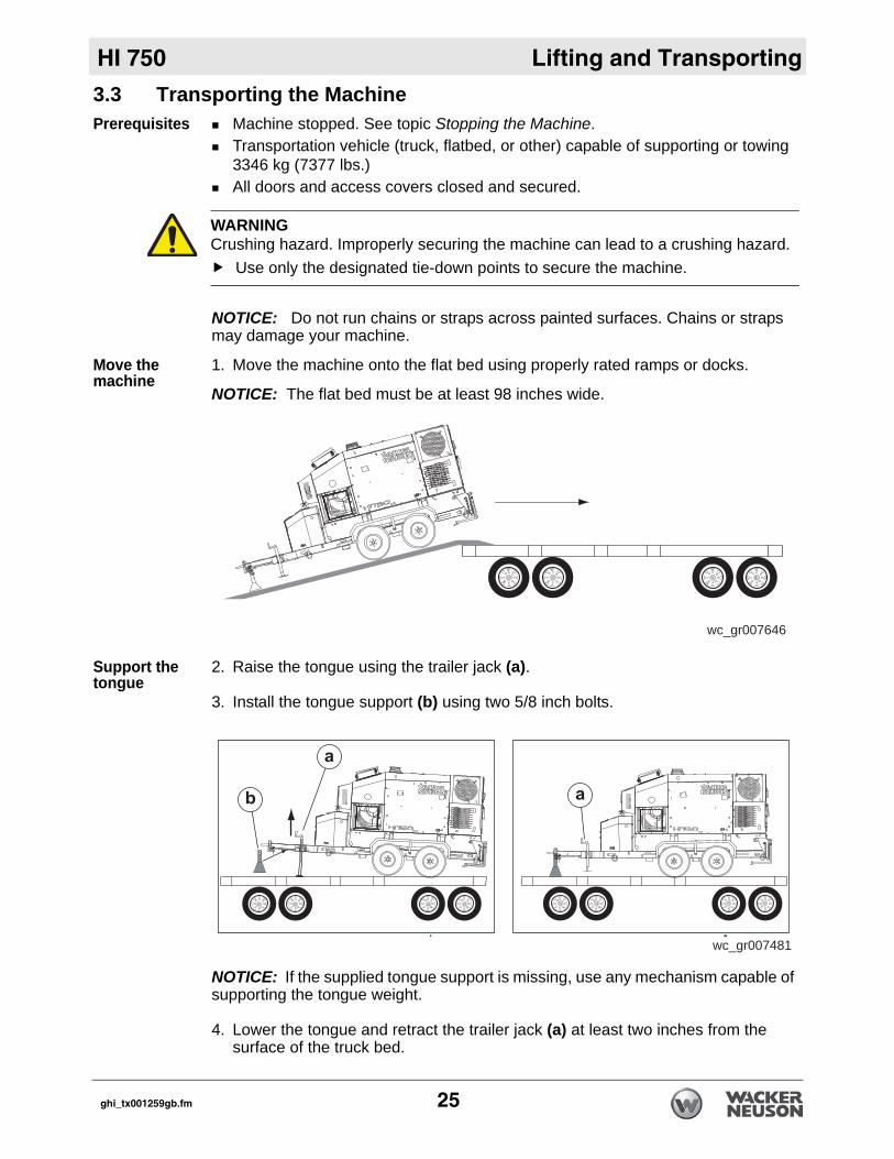
1. Move the machine onto the flat bed using properly rated ramps or docks.
NOTICE: The flat bed must be at least 98 inches wide.
Support the tongue
2. Raise the tongue using the trailer jack (a).
3. Install the tongue support (b) using two 5/8 inch bolts.
NOTICE: If the supplied tongue support is missing, use any mechanism capable of supporting the tongue weight.
4. Lower the tongue and retract the trailer jack (a) at least two inches from the surface of the truck bed.
WARNINGCrushing hazard. Improperly securing the machine can lead to a crushing hazard.
Use only the designated tie-down points to secure the machine.
wc_gr007646
wc_gr007481
ghi_tx001259gb.fm 25
Lifting and Transporting HI 750
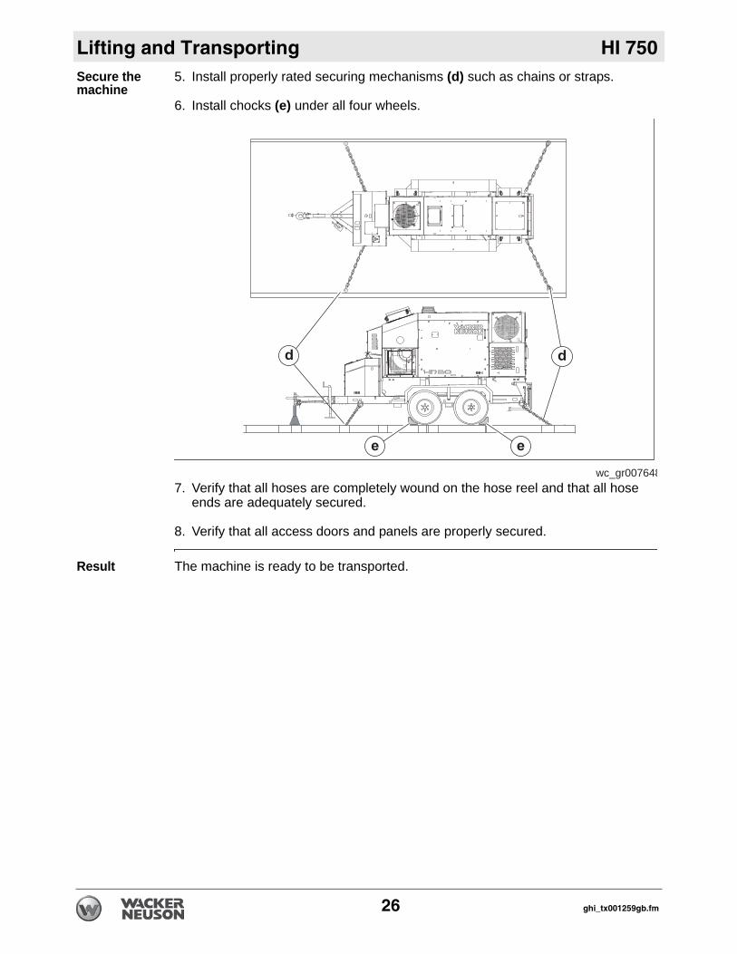
Secure the machine5. Install properly rated securing mechanisms (d) such as chains or straps.
6. Install chocks (e) under all four wheels.
7. Verify that all hoses are completely wound on the hose reel and that all hose ends are adequately secured.
8. Verify that all access doors and panels are properly secured.
Result The machine is ready to be transported.
wc_gr007648
26 ghi_tx001259gb.fm

HI 750 Lifting and Transporting
Notes:ghi_tx001259gb.fm 27
Operation HI 750
4 Operation4.1 Preparing the Machine for First UsePreparing for first use
To prepare your machine for first use:
1. Make sure all loose packaging materials have been removed from the machine.2. Check the machine and its components for damage. If there is visible damage,
do not operate the machine! Contact your Wacker Neuson dealer immediately for assistance.
3. Take inventory of all items included with the machine and verify that all loose components and fasteners are accounted for.
4. Attach component parts not already attached.5. Add fluids as needed and applicable, including fuel, engine oil, and battery acid.6. Move the machine to its operating location.
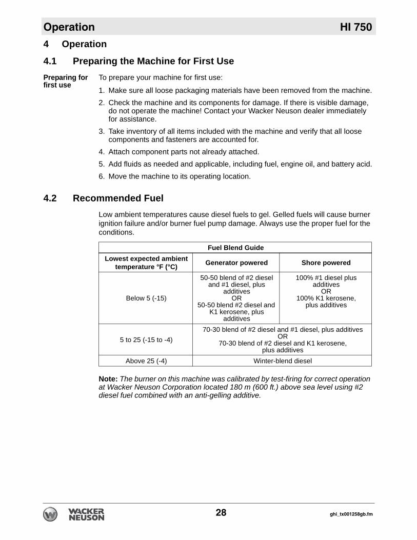
4.2 Recommended FuelLow ambient temperatures cause diesel fuels to gel. Gelled fuels will cause burner ignition failure and/or burner fuel pump damage. Always use the proper fuel for the conditions.
Note: The burner on this machine was calibrated by test-firing for correct operation at Wacker Neuson Corporation located 180 m (600 ft.) above sea level using #2 diesel fuel combined with an anti-gelling additive.
Fuel Blend GuideLowest expected ambient
temperature °F (°C) Generator powered Shore powered
Below 5 (-15)
50-50 blend of #2 diesel and #1 diesel, plus
additivesOR
50-50 blend #2 diesel and K1 kerosene, plus
additives
100% #1 diesel plus additives
OR100% K1 kerosene,
plus additives
5 to 25 (-15 to -4)70-30 blend of #2 diesel and #1 diesel, plus additives
OR 70-30 blend of #2 diesel and K1 kerosene,
plus additivesAbove 25 (-4) Winter-blend diesel
28 ghi_tx001258gb.fm
HI 750 Operation
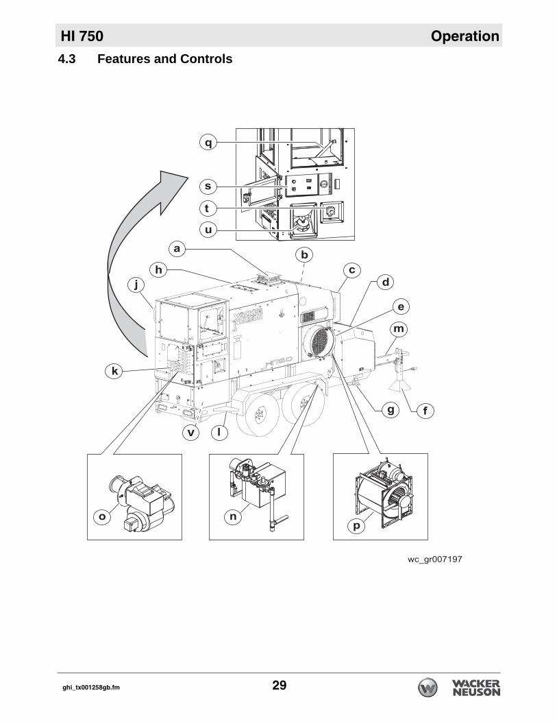
4.3 Features and Controlsv
ghi_tx001258gb.fm 29
Operation HI 750
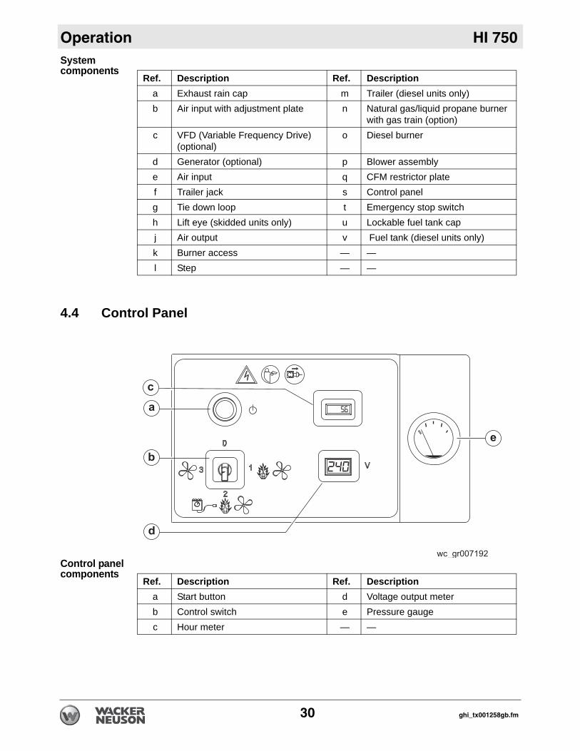
System components4.4 Control Panel
Control panel components
Ref. Description Ref. Descriptiona Exhaust rain cap m Trailer (diesel units only)b Air input with adjustment plate n Natural gas/liquid propane burner
with gas train (option)c VFD (Variable Frequency Drive)
(optional)o Diesel burner
d Generator (optional) p Blower assemblye Air input q CFM restrictor platef Trailer jack s Control panelg Tie down loop t Emergency stop switchh Lift eye (skidded units only) u Lockable fuel tank capj Air output v Fuel tank (diesel units only)k Burner access — —l Step — —
Ref. Description Ref. Descriptiona Start button d Voltage output meterb Control switch e Pressure gaugec Hour meter — —
30 ghi_tx001258gb.fm
HI 750 Operation
4.5 Positioning the MachineN
Guidelines Observe the following guidelines when positioning the machine for operation.Installer must be familiar with all applicable laws, codes, regulations, or other restrictions regarding installation of Indirect-fired (IDF) heaters.Installer must read and understand all OEM documents included with the machine. Machine must be on flat, firm surface.Installation must adhere to proximity restrictions.
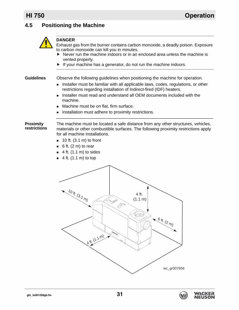
Proximity restrictions
The machine must be located a safe distance from any other structures, vehicles, materials or other combustible surfaces. The following proximity restrictions apply for all machine installations.
10 ft. (3.1 m) to front6 ft. (2 m) to rear4 ft. (1.1 m) to sides4 ft. (1.1 m) to top
DANGERExhaust gas from the burner contains carbon monoxide, a deadly poison. Exposure to carbon monoxide can kill you in minutes.
Never run the machine indoors or in an enclosed area unless the machine is vented properly. If your machine has a generator, do not run the machine indoors.
wc_gr007656
10 ft. (3.1 m)
4 ft. (1.1 m)
4 ft. (1.1 m)
6 ft. (2 m)
ghi_tx001258gb.fm 31
Operation HI 750
4.6 Suggested VentingWhen installing vents:Do not use B-vent exhaust pipes to vent an oil burning machine. Contact Wacker Neuson Product Support for recommended alternatives. Adhere to all local and national codes.Adhere to all fire prevention regulations.Consult all appropriate governing bodies or local contractor for venting and fresh air requirements. Make sure that the room or building to be heated has sufficient ventilation to ensure that the machine has enough air to function prop-erly.Position the machine in a manner that avoids excessive vent bends (elbows), and long horizontal runs.Keep air inlets and outlets free from obstruction. Ensure that there are no bulky objects or sheets/covers near or on the machine.Route the venting pipes in a manner that avoids flammable materials. Route the venting pipes in a manner that avoids contact with people.When the machine is connected to a flue pipe, the flue pipe shall terminate in a vertical section at least two feet long. Sufficient draft shall be created to assure safe and proper operation of the machine (minimum -0.02” wc).
DANGERAsphyxiation hazard.Exhaust gas from the burner contains carbon monoxide, a deadly poison. Exposure to carbon monoxide can kill you in minutes.
Never run the machine indoors or in an enclosed area unless the machine is vented properly according to local and national codes.
32 ghi_tx001258gb.fm
HI 750 Operation
4.7 Before StartingPrerequisites Machine properly positionedPower connected to the machine
Checks Before starting the machine, check the following items:
Note: The remote thermostat or thermostat receptacle plug must be installed in order for the machine to operate.
Result The machine is ready to have power applied.
4.8 Generator Power RequirementsNOTICE: Machine damage may occur if a generator with an undersized motor is used to power the machine. The starting kVA of the generator motor must be at least 33 kVA at a maximum voltage dip of 20%.
Item TaskFuel Check that the fuel tank is full (if applicable). See
topic Recommended Fuels.Fuel tank cap Check that the fuel tank cap is secure.
Control switch The control switch must be in the “off” (0) position.Main control panel Check that proper power supplies have been con-
nected. See topics Connecting Power to the Machine and Powering-Up to the Machine.
Remote thermostat/thermostat receptacle plug
Check that the remote thermostat (or the recepta-cle plug) has been correctly intalled. See topic Installing the Remote Thermostat.
Ducts and duct adapters Check that all ducts and duct adapters have been properly installed. See chapter Accessories.
Generator Check that the generator is properly maintained. See the OEM documentation for more information.
ghi_tx001258gb.fm 33
Operation HI 750
4.9 Installing the Remote ThermostatRequirements Remote thermostat
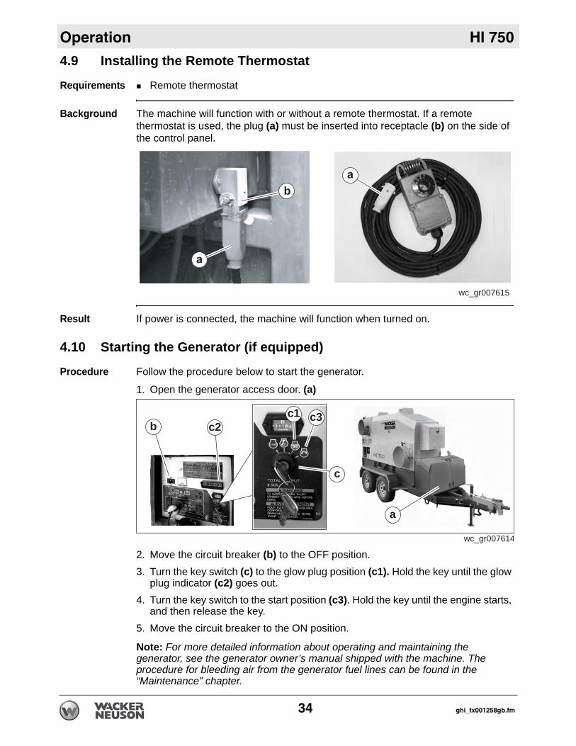
Background The machine will function with or without a remote thermostat. If a remote thermostat is used, the plug (a) must be inserted into receptacle (b) on the side of the control panel.
Result If power is connected, the machine will function when turned on.
4.10 Starting the Generator (if equipped)
Procedure Follow the procedure below to start the generator.
1. Open the generator access door. (a)
2. Move the circuit breaker (b) to the OFF position.3. Turn the key switch (c) to the glow plug position (c1). Hold the key until the glow
plug indicator (c2) goes out.4. Turn the key switch to the start position (c3). Hold the key until the engine starts,
and then release the key.5. Move the circuit breaker to the ON position.
Note: For more detailed information about operating and maintaining the generator, see the generator owner’s manual shipped with the machine. The procedure for bleeding air from the generator fuel lines can be found in the “Maintenance” chapter.
wc_gr007615
b
wc_gr007614
a
b c2c3c1
c
34 ghi_tx001258gb.fm
HI 750 Operation
4.11 StartingRequirements Machine properly positionedPower connected or generator startedPre-starting checks complete
Procedure Follow the procedure below to start the machine.
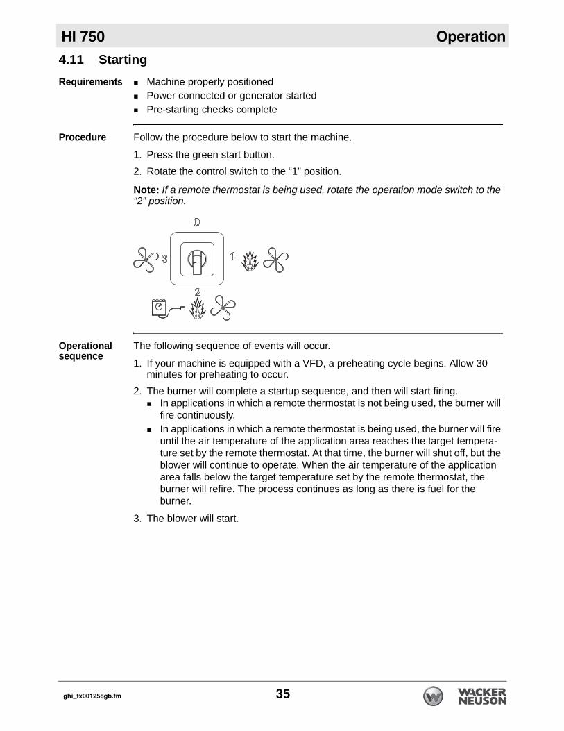
1. Press the green start button.2. Rotate the control switch to the “1” position.
Note: If a remote thermostat is being used, rotate the operation mode switch to the “2” position.
Operational sequence
The following sequence of events will occur.
1. If your machine is equipped with a VFD, a preheating cycle begins. Allow 30 minutes for preheating to occur.
2. The burner will complete a startup sequence, and then will start firing.In applications in which a remote thermostat is not being used, the burner will fire continuously.In applications in which a remote thermostat is being used, the burner will fire until the air temperature of the application area reaches the target tempera-ture set by the remote thermostat. At that time, the burner will shut off, but the blower will continue to operate. When the air temperature of the application area falls below the target temperature set by the remote thermostat, the burner will refire. The process continues as long as there is fuel for the burner.
3. The blower will start.
ghi_tx001258gb.fm 35
Operation HI 750
4.12 Monitoring the Operating ParametersBackground Monitor the machine while it is operating to ensure safe and efficient operation.Parameters Monitor the following parameters while the machine is operating.
4.13 StoppingProcedure Follow the procedure below to stop the machine.
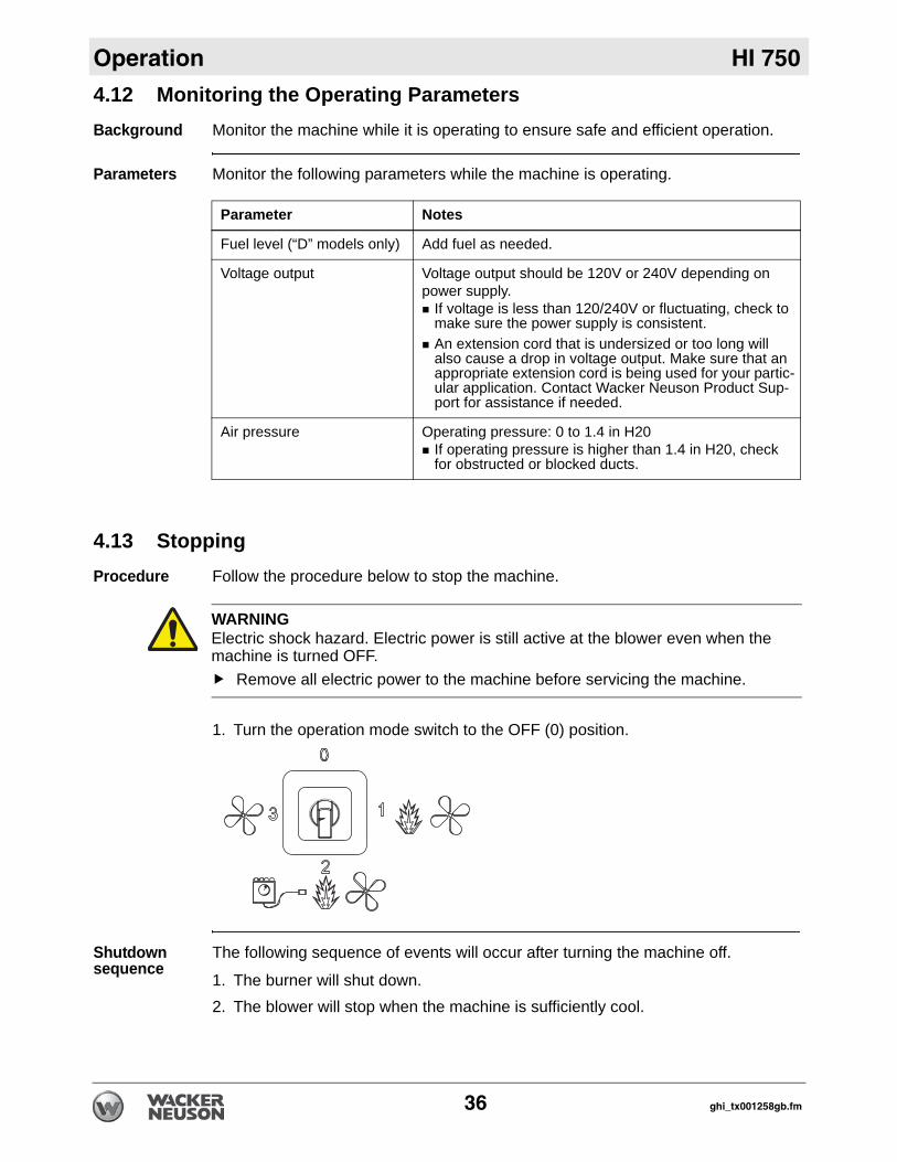
1. Turn the operation mode switch to the OFF (0) position.
Shutdown sequence
The following sequence of events will occur after turning the machine off.
1. The burner will shut down. 2. The blower will stop when the machine is sufficiently cool.
Parameter Notes
Fuel level (“D” models only) Add fuel as needed.
Voltage output Voltage output should be 120V or 240V depending on power supply.
If voltage is less than 120/240V or fluctuating, check to make sure the power supply is consistent. An extension cord that is undersized or too long will also cause a drop in voltage output. Make sure that an appropriate extension cord is being used for your partic-ular application. Contact Wacker Neuson Product Sup-port for assistance if needed.
Air pressure Operating pressure: 0 to 1.4 in H20If operating pressure is higher than 1.4 in H20, check for obstructed or blocked ducts.
WARNINGElectric shock hazard. Electric power is still active at the blower even when the machine is turned OFF.
Remove all electric power to the machine before servicing the machine.
36 ghi_tx001258gb.fm
HI 750 Operation
4.14 Emergency Shutdown ProcedureBackground This machine is equipped with an emergency stop pushbutton. When pressed, thispushbutton shuts down the machine and disconnects all power to the machine controls.
NOTICE: Do not use the emergency stop pushbutton for normal shutdown.
Stopping the machine
To stop the machine and lock out all power to the controls during an emergency, carry out the following procedure:
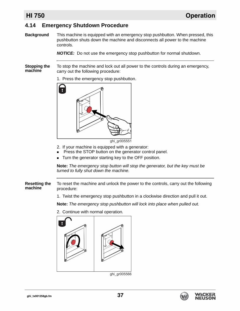
1. Press the emergency stop pushbutton.
2. If your machine is equipped with a generator: Press the STOP button on the generator control panel. Turn the generator starting key to the OFF position.
Note: The emergency stop button will stop the generator, but the key must be turned to fully shut down the machine.
Resetting the machine
To reset the machine and unlock the power to the controls, carry out the following procedure:
1. Twist the emergency stop pushbutton in a clockwise direction and pull it out.
Note: The emergency stop pushbutton will lock into place when pulled out.
2. Continue with normal operation.
ghi_tx001258gb.fm 37
Operation HI 750
4.15 High Temperature ResetsOverview The machine includes two high temperature reset buttons. The reset buttons mustbe pressed if the machine has been shut down improperly (for example, if the fan is stopped before the machine is cool).
Prerequisite Machine is stopped and cool to the touch
Procedure Follow the procedure below to manually reset the high temperature buttons.
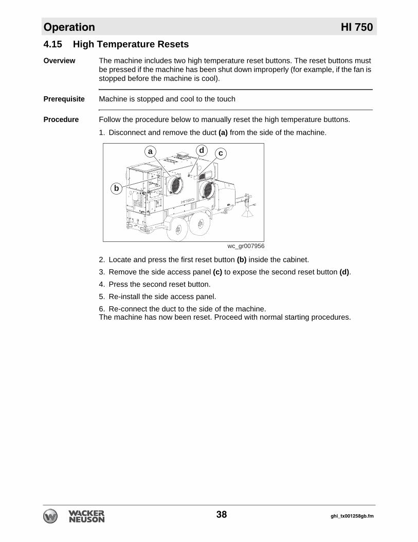
1. Disconnect and remove the duct (a) from the side of the machine.
2. Locate and press the first reset button (b) inside the cabinet.3. Remove the side access panel (c) to expose the second reset button (d).4. Press the second reset button.5. Re-install the side access panel.6. Re-connect the duct to the side of the machine.The machine has now been reset. Proceed with normal starting procedures.
wc_gr007956
a
b
cd
38 ghi_tx001258gb.fm
HI 750 Operation
4.16 Operating at High Elevations Background If using the machine at or above elevations of 1524 m (5000 ft.) asl, periodicmonitoring and additional maintenance are necessary to preserve the machine’s systems. The following procedures will ensure that the machine runs smoothly and that premature soot build-up will be reduced.
Guidelines Use the guidelines below to ensure efficient operation of the machine. Refer to the specific topic for details.
High Elevation Nozzle
Wacker Neuson Corporation recommends using a 3.75-60° B @ 150 psi nozzle when operating at high elevations. Contact Wacker Neuson Product Support to order a replacement nozzle.
Task When See Topic1. Conduct a smoke spot test. After making any adjustments
and/orEvery 1000 hours
7.2
2. Adjust the air output volume and CFM settings
Before operation 4.14 & 4.15
3. Adjust the fuel pressure Before operation 7.6 & 8.7
4. Replace the burner nozzle Before operation 9.2
WARNINGFire hazard. The use of incorrect nozzles could cause fire or impaired combustion. Impaired combustion may cause under-firing, over-firing, sooting, sudden expulsion of hot gases, and smoke.
Use only the factory-installed or recommended nozzles.
ghi_tx001258gb.fm 39
Operation HI 750
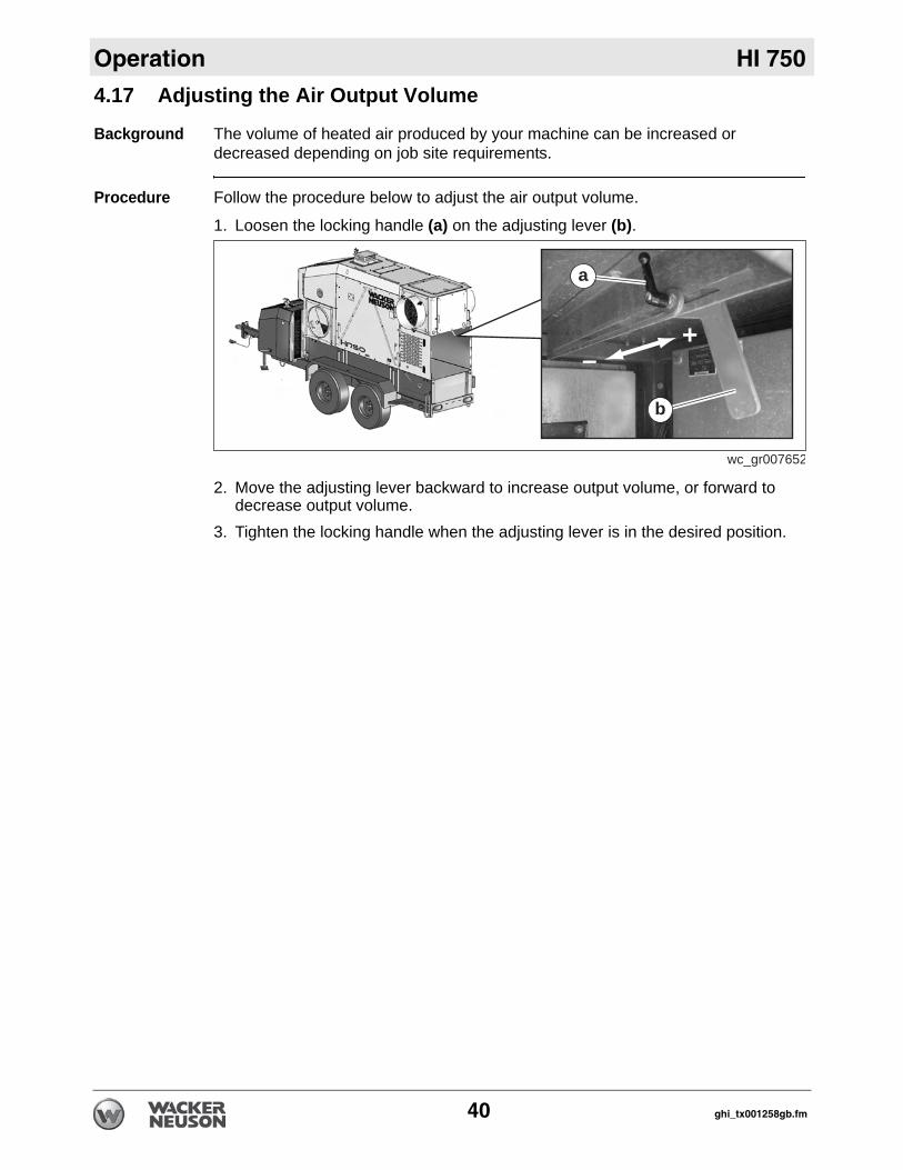
4.17 Adjusting the Air Output VolumeBackground The volume of heated air produced by your machine can be increased or decreased depending on job site requirements.
Procedure Follow the procedure below to adjust the air output volume.
1. Loosen the locking handle (a) on the adjusting lever (b).
2. Move the adjusting lever backward to increase output volume, or forward to decrease output volume.
3. Tighten the locking handle when the adjusting lever is in the desired position.
wc_gr007652
+–
a
b
40 ghi_tx001258gb.fm
HI 750 Operation
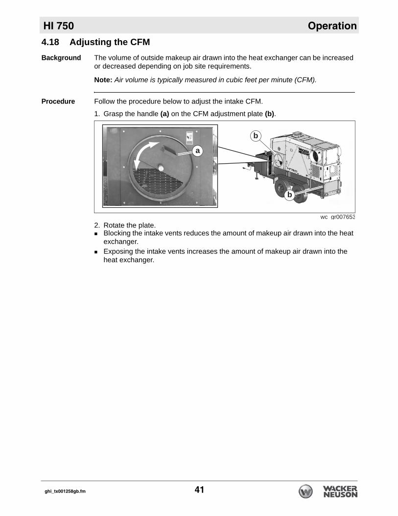
4.18 Adjusting the CFMBackground The volume of outside makeup air drawn into the heat exchanger can be increasedor decreased depending on job site requirements.
Note: Air volume is typically measured in cubic feet per minute (CFM).
Procedure Follow the procedure below to adjust the intake CFM.
1. Grasp the handle (a) on the CFM adjustment plate (b).
2. Rotate the plate. Blocking the intake vents reduces the amount of makeup air drawn into the heat exchanger. Exposing the intake vents increases the amount of makeup air drawn into the heat exchanger.
wc gr007653
b
b
a
ghi_tx001258gb.fm 41
Operation HI 750
Notes:42 ghi_tx001258gb.fm
HI 750 Factory-Installed Options
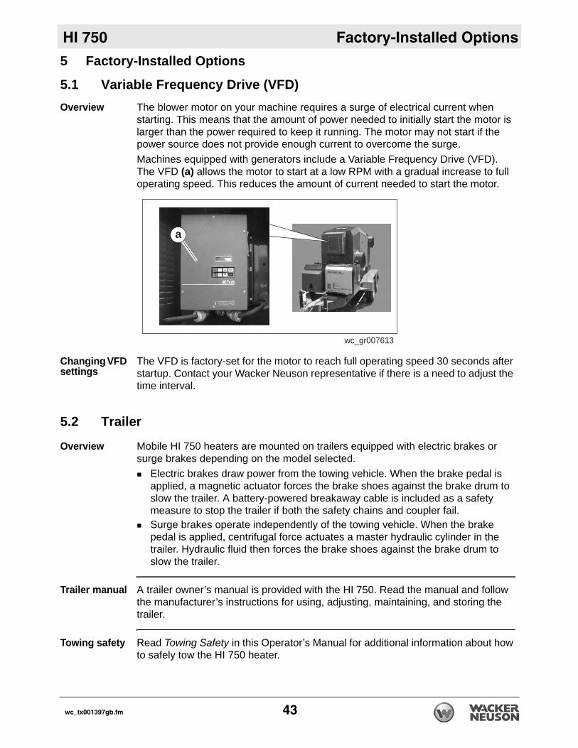
5 Factory-Installed Options5.1 Variable Frequency Drive (VFD)Overview The blower motor on your machine requires a surge of electrical current when
starting. This means that the amount of power needed to initially start the motor is larger than the power required to keep it running. The motor may not start if the power source does not provide enough current to overcome the surge.Machines equipped with generators include a Variable Frequency Drive (VFD). The VFD (a) allows the motor to start at a low RPM with a gradual increase to full operating speed. This reduces the amount of current needed to start the motor.
Changing VFD settings
The VFD is factory-set for the motor to reach full operating speed 30 seconds after startup. Contact your Wacker Neuson representative if there is a need to adjust the time interval.
5.2 Trailer
Overview Mobile HI 750 heaters are mounted on trailers equipped with electric brakes or surge brakes depending on the model selected.
Electric brakes draw power from the towing vehicle. When the brake pedal is applied, a magnetic actuator forces the brake shoes against the brake drum to slow the trailer. A battery-powered breakaway cable is included as a safety measure to stop the trailer if both the safety chains and coupler fail.Surge brakes operate independently of the towing vehicle. When the brake pedal is applied, centrifugal force actuates a master hydraulic cylinder in the trailer. Hydraulic fluid then forces the brake shoes against the brake drum to slow the trailer.
Trailer manual A trailer owner’s manual is provided with the HI 750. Read the manual and follow the manufacturer’s instructions for using, adjusting, maintaining, and storing the trailer.
Towing safety Read Towing Safety in this Operator’s Manual for additional information about how to safely tow the HI 750 heater.
wc_gr007613
a
wc_tx001397gb.fm 43
Factory-Installed Options HI 750
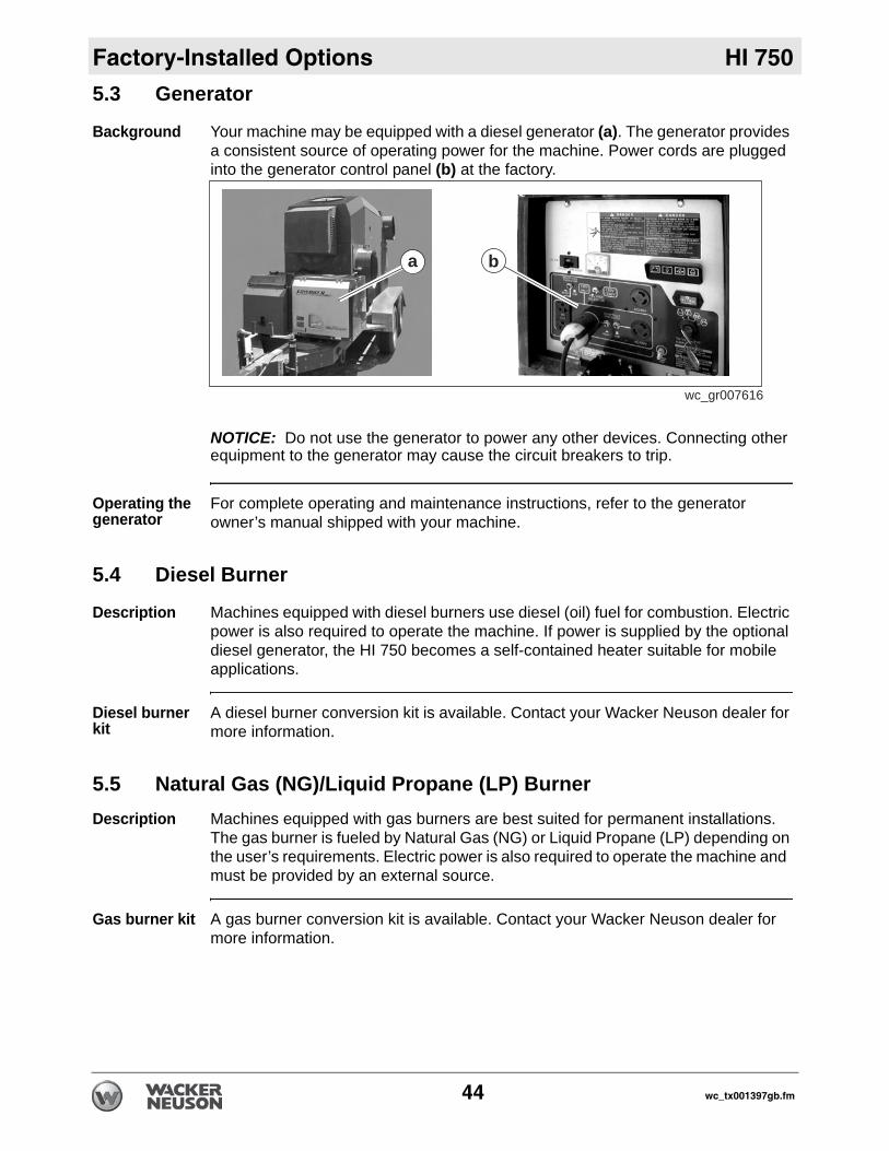
5.3 GeneratorBackground Your machine may be equipped with a diesel generator (a). The generator provides a consistent source of operating power for the machine. Power cords are plugged into the generator control panel (b) at the factory.
NOTICE: Do not use the generator to power any other devices. Connecting other equipment to the generator may cause the circuit breakers to trip.
Operating the generator
For complete operating and maintenance instructions, refer to the generator owner’s manual shipped with your machine.
5.4 Diesel Burner
Description Machines equipped with diesel burners use diesel (oil) fuel for combustion. Electric power is also required to operate the machine. If power is supplied by the optional diesel generator, the HI 750 becomes a self-contained heater suitable for mobile applications.
Diesel burner kit
A diesel burner conversion kit is available. Contact your Wacker Neuson dealer for more information.
5.5 Natural Gas (NG)/Liquid Propane (LP) BurnerDescription Machines equipped with gas burners are best suited for permanent installations.
The gas burner is fueled by Natural Gas (NG) or Liquid Propane (LP) depending on the user’s requirements. Electric power is also required to operate the machine and must be provided by an external source.
Gas burner kit A gas burner conversion kit is available. Contact your Wacker Neuson dealer for more information.
wc_gr007616
a b
44 wc_tx001397gb.fm
HI 750 Accessories
6 Accessories6.1 Available Accessories
Available Accessories
The following Wacker Neuson accessories are available. Contact us for more information.
Item Description/PurposeRemote thermostat Allows the user to remotely control the target tempera-
tureInlet and outlet covers Vinyl covers that protect the interior of the machine
from the elements during transport or storageDuct adapters-various sizes Various sizes of detachable inlet and outlet adaptersFlexible ducts—various sizes Vinyl ducts that offer a method of directing inlet and
outlet airBurner conversion kits Allows the user to switch the fuel source from DSL to
NG/LP and vice-versa
wc_tx001398gb.fm 45
Accessories HI 750
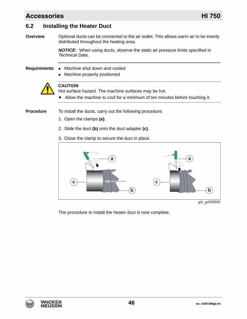
6.2 Installing the Heater DuctOverview Optional ducts can be connected to the air outlet. This allows warm air to be evenly distributed throughout the heating area.
NOTICE: When using ducts, observe the static air pressure limits specified in Technical Data.
Requirements Machine shut down and cooledMachine properly positioned
Procedure To install the ducts, carry out the following procedure.
1. Open the clamps (a).
2. Slide the duct (b) onto the duct adapter (c).
3. Close the clamp to secure the duct in place.
The procedure to install the heater duct is now complete.
CAUTIONHot surface hazard. The machine surfaces may be hot.
Allow the machine to cool for a minimum of ten minutes before touching it.
46 wc_tx001398gb.fm
HI 750 Accessories
6.3 Installing the Remote ThermostatPrerequisites Remote thermostatMachine properly positionedPre-starting checks complete
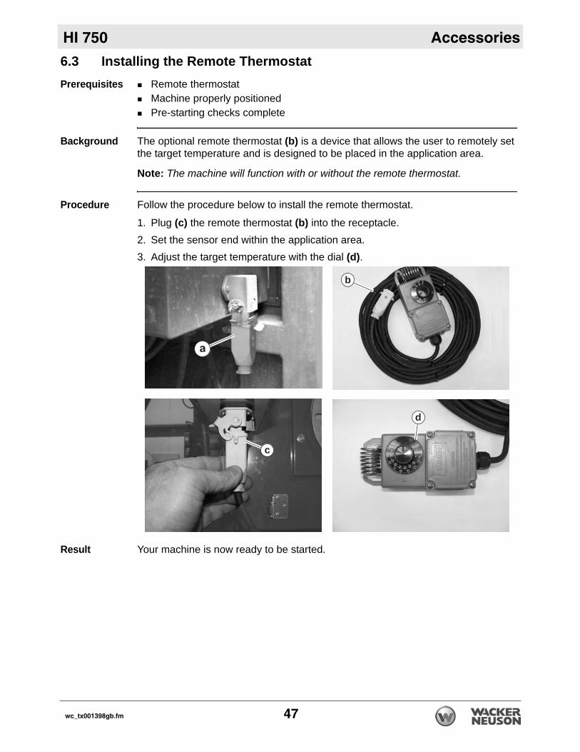
Background The optional remote thermostat (b) is a device that allows the user to remotely set the target temperature and is designed to be placed in the application area.
Note: The machine will function with or without the remote thermostat.
Procedure Follow the procedure below to install the remote thermostat.
1. Plug (c) the remote thermostat (b) into the receptacle.2. Set the sensor end within the application area.3. Adjust the target temperature with the dial (d).
Result Your machine is now ready to be started.
c
a
b
d
wc_tx001398gb.fm 47
Burner Setup—Oil HI 750
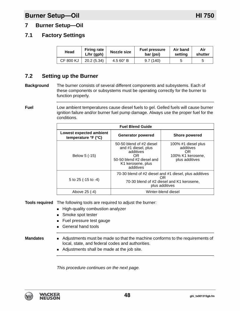
7 Burner Setup—Oil7.1 Factory Settings
7.2 Setting up the BurnerBackground The burner consists of several different components and subsystems. Each of
these components or subsystems must be operating correctly for the burner to function properly.
Fuel Low ambient temperatures cause diesel fuels to gel. Gelled fuels will cause burner ignition failure and/or burner fuel pump damage. Always use the proper fuel for the conditions.
Tools required The following tools are required to adjust the burner:High-quality combustion analyzer Smoke spot testerFuel pressure test gaugeGeneral hand tools
Mandates Adjustments must be made so that the machine conforms to the requirements of local, state, and federal codes and authorities. Adjustments shall be made at the job site.
This procedure continues on the next page.
Head Firing rateL/hr (gph) Nozzle size Fuel pressure
bar (psi)Air bandsetting
Air shutter
CF 800 KJ 20.2 (5.34) 4.5 60° B 9.7 (140) 5 5
Fuel Blend GuideLowest expected ambient
temperature °F (°C) Generator powered Shore powered
Below 5 (-15)
50-50 blend of #2 diesel and #1 diesel, plus
additivesOR
50-50 blend #2 diesel and K1 kerosene, plus
additives
100% #1 diesel plus additives
OR100% K1 kerosene,
plus additives
5 to 25 (-15 to -4)70-30 blend of #2 diesel and #1 diesel, plus additives
OR 70-30 blend of #2 diesel and K1 kerosene,
plus additivesAbove 25 (-4) Winter-blend diesel
48 ghi_tx001315gb.fm
HI 750 Burner Setup—Oil
Continued from the previous page.When Adjust the burner:Before operating the machine at elevations 305 m (1,000 ft) above or below the location of the previous adjustmentsBefore starting at a new job siteAfter any burner maintenance or repair has been performedIf burner performance is in question
Procedure Follow the procedure below to set up the burner.
1. Shut down the machine.
2. Set the burner electrodes.(See topic Setting/Checking the Electrodes.)
3. Check the burner nozzle.(See topic Replacing the Burner Nozzle.)
4. Check/set the “Z” distance.(See topic Setting the “Z” Distance.)
5. Set the air settings.(See topic Adjusting the Air Settings.)
6. Start the machine and the burner.
7. Check/set the fuel pressure.(See topic Adjusting the Fuel Pressure.)
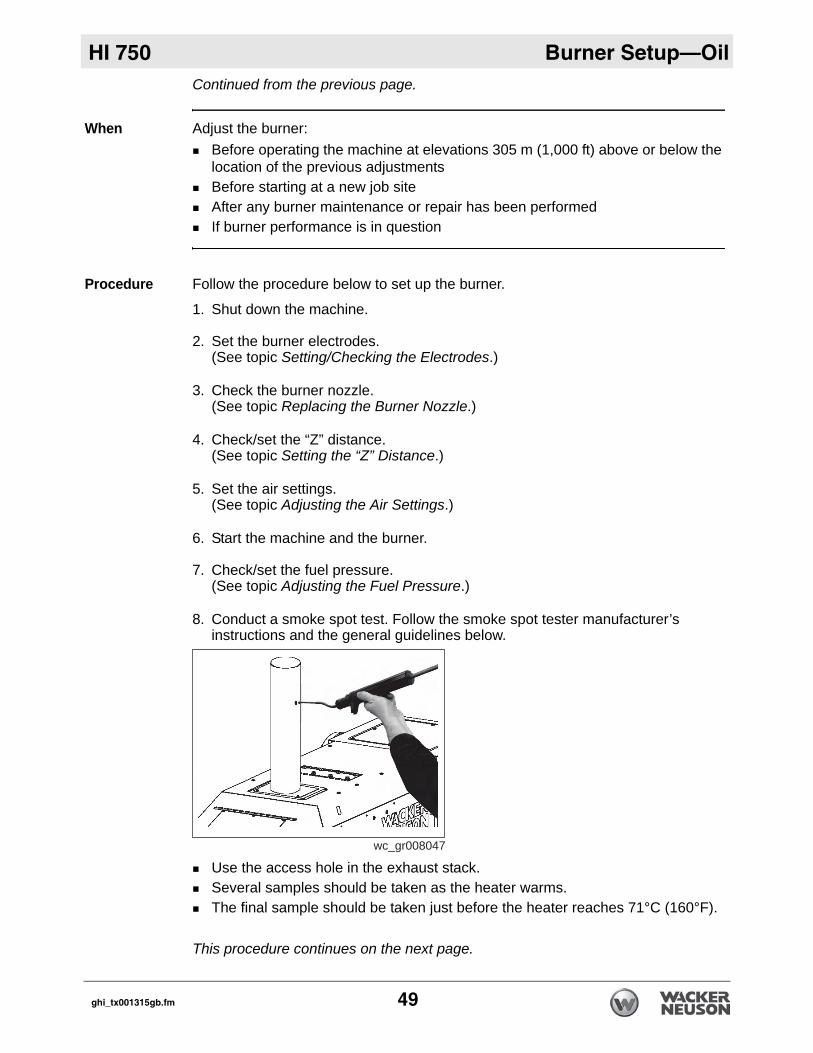
8. Conduct a smoke spot test. Follow the smoke spot tester manufacturer’s instructions and the general guidelines below.
Use the access hole in the exhaust stack.Several samples should be taken as the heater warms.The final sample should be taken just before the heater reaches 71°C (160°F).
This procedure continues on the next page.
wc_gr008047
ghi_tx001315gb.fm 49
Burner Setup—Oil HI 750
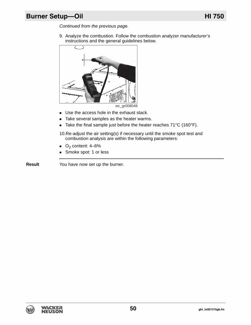
Continued from the previous page.9. Analyze the combustion. Follow the combustion analyzer manufacturer’s instructions and the general guidelines below.
Use the access hole in the exhaust stack.Take several samples as the heater warms. Take the final sample just before the heater reaches 71°C (160°F).
10.Re-adjust the air setting(s) if necessary until the smoke spot test and combustion analysis are within the following parameters:O2 content: 4–6% Smoke spot: 1 or less
Result You have now set up the burner.
wc_gr008048
50 ghi_tx001315gb.fm
HI 750 Burner Setup—Oil
7.3 Setting/Checking the ElectrodesPrerequisites Power supplies disconnectedMeasuring device
Procedure Follow the procedure below to check the electrodes. Note: Procedure shows the “F” head.
1. Disconnect the power supplies.
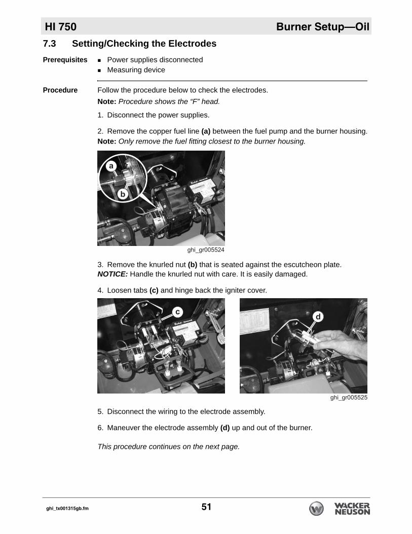
2. Remove the copper fuel line (a) between the fuel pump and the burner housing.Note: Only remove the fuel fitting closest to the burner housing.
3. Remove the knurled nut (b) that is seated against the escutcheon plate.NOTICE: Handle the knurled nut with care. It is easily damaged.
4. Loosen tabs (c) and hinge back the igniter cover..
5. Disconnect the wiring to the electrode assembly.
6. Maneuver the electrode assembly (d) up and out of the burner.
This procedure continues on the next page.
ghi_tx001315gb.fm 51
Burner Setup—Oil HI 750
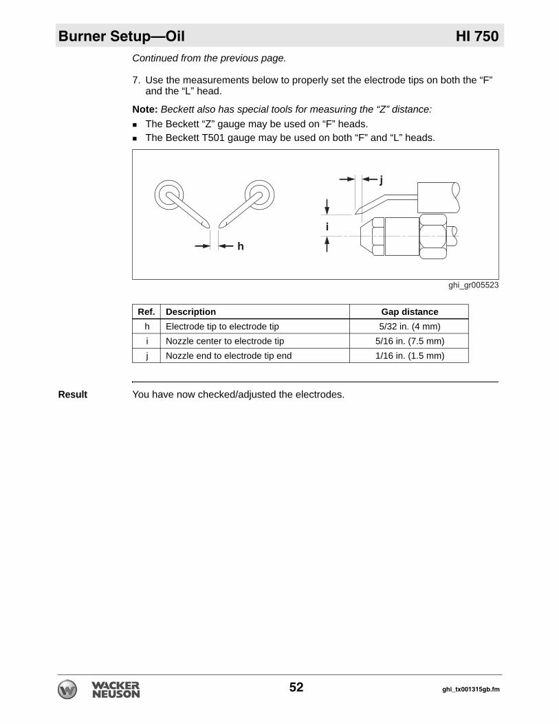
Continued from the previous page.7. Use the measurements below to properly set the electrode tips on both the “F” and the “L” head.
Note: Beckett also has special tools for measuring the “Z” distance:The Beckett “Z” gauge may be used on “F” heads.The Beckett T501 gauge may be used on both “F” and “L” heads.
Result You have now checked/adjusted the electrodes.
Ref. Description Gap distanceh Electrode tip to electrode tip 5/32 in. (4 mm)i Nozzle center to electrode tip 5/16 in. (7.5 mm)j Nozzle end to electrode tip end 1/16 in. (1.5 mm)
52 ghi_tx001315gb.fm
HI 750 Burner Setup—Oil
7.4 Setting the “Z” DistancePrerequisites Burner removed from the machineT501 gauge
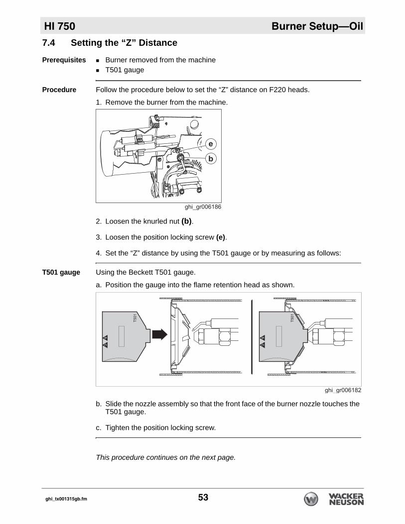
Procedure Follow the procedure below to set the “Z” distance on F220 heads.
1. Remove the burner from the machine.
2. Loosen the knurled nut (b).
3. Loosen the position locking screw (e).
4. Set the “Z” distance by using the T501 gauge or by measuring as follows:
T501 gauge Using the Beckett T501 gauge.
a. Position the gauge into the flame retention head as shown.
b. Slide the nozzle assembly so that the front face of the burner nozzle touches the T501 gauge.
c. Tighten the position locking screw.
This procedure continues on the next page.
ghi_tx001315gb.fm 53
Burner Setup—Oil HI 750
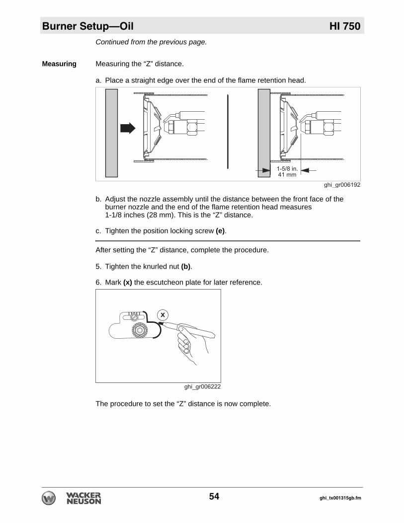
Continued from the previous page.Measuring Measuring the “Z” distance.
a. Place a straight edge over the end of the flame retention head.
b. Adjust the nozzle assembly until the distance between the front face of the burner nozzle and the end of the flame retention head measures 1-1/8 inches (28 mm). This is the “Z” distance.
c. Tighten the position locking screw (e).
After setting the “Z” distance, complete the procedure.
5. Tighten the knurled nut (b).
6. Mark (x) the escutcheon plate for later reference.
The procedure to set the “Z” distance is now complete.
x
54 ghi_tx001315gb.fm
HI 750 Burner Setup—Oil
7.5 Adjusting the Air SettingsFactory settings
Air band: 5Air shutter: 5
These settings are initial settings only. Adjust the air settings as necessary to obtain the proper smoke spot and combustion analysis values.
Background There are two parts to adjusting the air setting: 1) air band; and 2) air shutter. Adjust the air band to make large adjustments. Adjust the air shutter to make small adjustments.
Effects The air setting has the following effects on combustion.Higher O2 percentage (excess air settings) lowers soot production but raises stack temperature and reduces efficiency: lean mixture.Lower O2 percentage (inadequate air settings) increases efficiency and lowers stack temperature but may cause soot build-up: rich mixture.
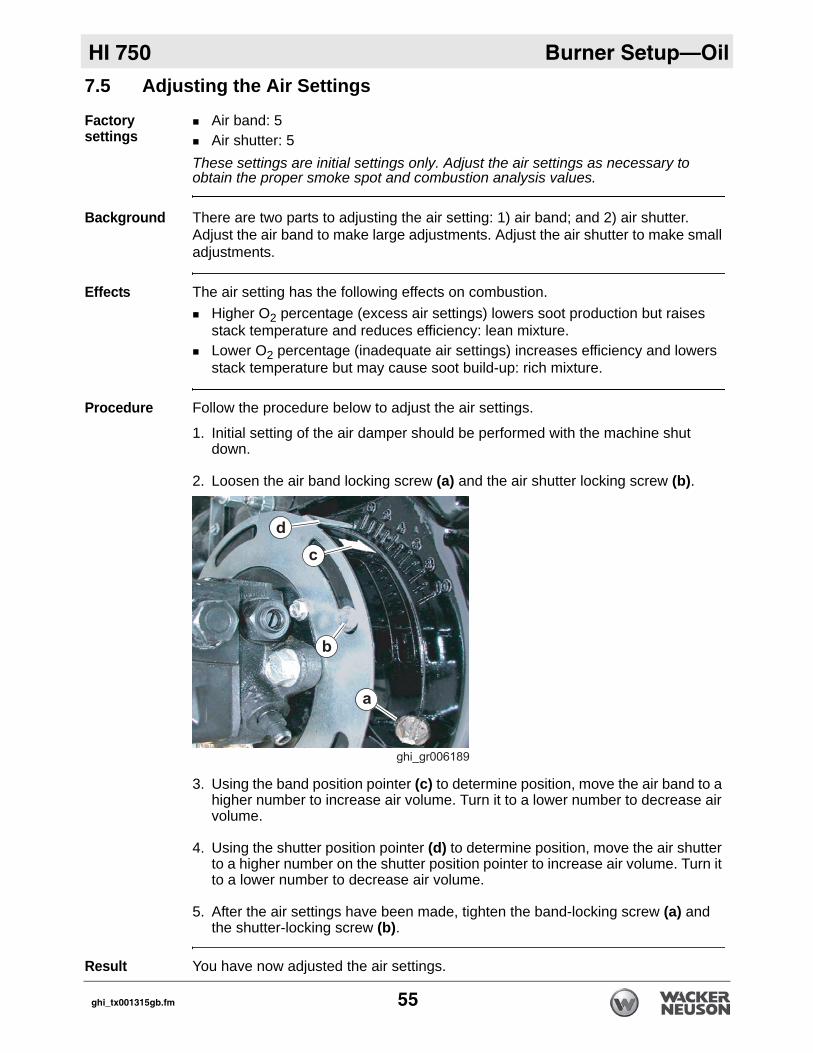
Procedure Follow the procedure below to adjust the air settings.
1. Initial setting of the air damper should be performed with the machine shut down.
2. Loosen the air band locking screw (a) and the air shutter locking screw (b).
3. Using the band position pointer (c) to determine position, move the air band to a higher number to increase air volume. Turn it to a lower number to decrease air volume.
4. Using the shutter position pointer (d) to determine position, move the air shutter to a higher number on the shutter position pointer to increase air volume. Turn it to a lower number to decrease air volume.
5. After the air settings have been made, tighten the band-locking screw (a) and the shutter-locking screw (b).
Result You have now adjusted the air settings.
ghi_tx001315gb.fm 55
Burner Setup—Oil HI 750
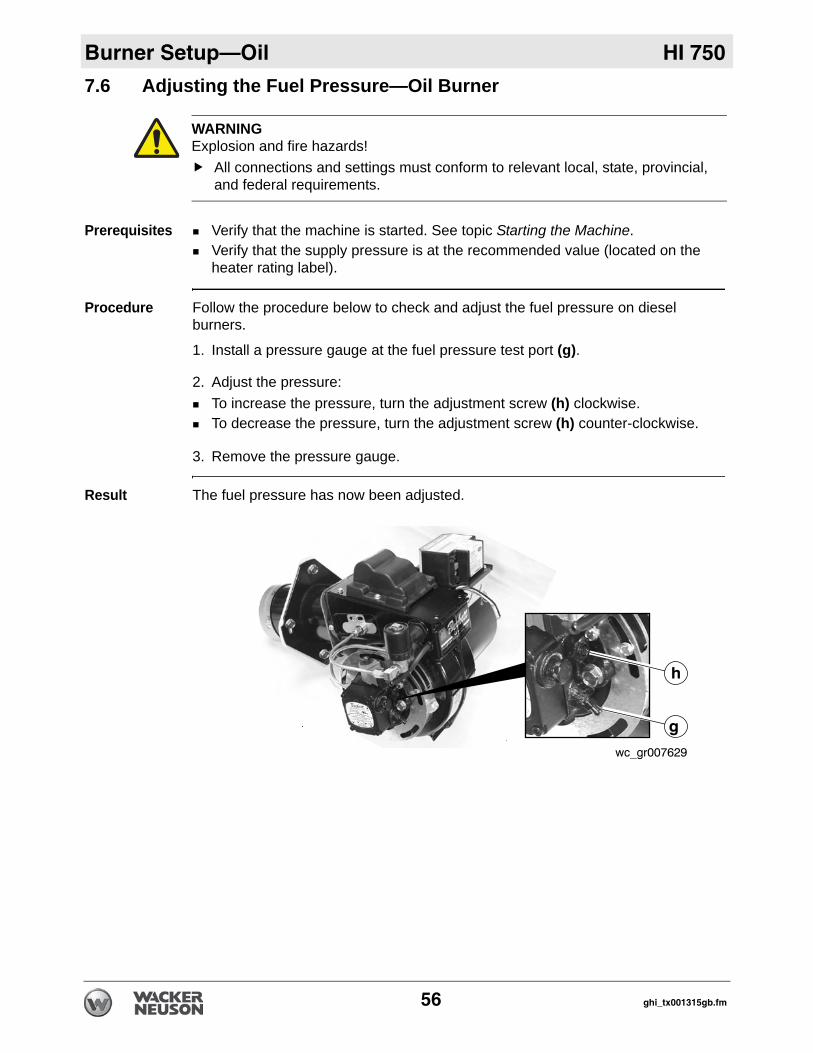
7.6 Adjusting the Fuel Pressure—Oil BurnerPrerequisites Verify that the machine is started. See topic Starting the Machine.Verify that the supply pressure is at the recommended value (located on the heater rating label).
Procedure Follow the procedure below to check and adjust the fuel pressure on diesel burners.
1. Install a pressure gauge at the fuel pressure test port (g).
2. Adjust the pressure: To increase the pressure, turn the adjustment screw (h) clockwise. To decrease the pressure, turn the adjustment screw (h) counter-clockwise.
3. Remove the pressure gauge.
Result The fuel pressure has now been adjusted.
WARNINGExplosion and fire hazards!
All connections and settings must conform to relevant local, state, provincial, and federal requirements.
wc_gr007629
g
h
56 ghi_tx001315gb.fm
HI 750 Burner Setup—Gas
8 Burner Setup—Gas8.1 Factory Settings
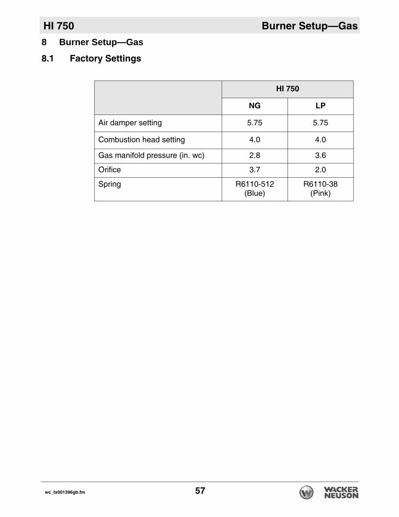
HI 750
NG LP
Air damper setting 5.75 5.75
Combustion head setting 4.0 4.0
Gas manifold pressure (in. wc) 2.8 3.6
Orifice 3.7 2.0
Spring R6110-512 (Blue)
R6110-38(Pink)
wc_tx001396gb.fm 57
Burner Setup—Gas HI 750
8.2 Setting up the BurnerBackground The burner consists of several different components and subsystems. Each of these components or subsystems must be operating correctly for the burner to function properly.
Tools required The following tools are required to adjust the burner:High-quality combustion analyzer Smoke spot testerManometerGeneral hand tools
Mandates Adjustments made shall be done so that the machine conforms to the require-ments of local, state, and federal codes and authorities. Adjustments shall be made at the job site.
When to adjust
Adjust the burner:Before operating the machine at elevations 305 m (1,000 ft) above or below the location of where the last adjustments were madeBefore starting at a new job siteAfter any burner maintenance or repair has been performedIf burner performance is in question
Procedure Follow the procedure below to set up the burner.
1. Shut down the machine.2. Adjust the ionization probe and the electrode.
(See topic 8.3)
3. Check the burner orifice.(See topic 8.4)
4. Set the air settings.(See topic 8.5)
5. Start the machine and the burner.6. Check/set the supply gas pressure.
(See topic 8.6)7. Check/set the burner gas pressure.
(See topic 8.7)
This procedure continues on the next page.
58 wc_tx001396gb.fm
HI 750 Burner Setup—Gas
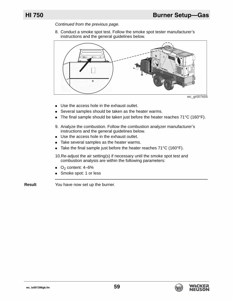
Continued from the previous page.8. Conduct a smoke spot test. Follow the smoke spot tester manufacturer’s instructions and the general guidelines below.
Use the access hole in the exhaust outlet.Several samples should be taken as the heater warms.The final sample should be taken just before the heater reaches 71°C (160°F).
9. Analyze the combustion. Follow the combustion analyzer manufacturer’s instructions and the general guidelines below.Use the access hole in the exhaust outlet.Take several samples as the heater warms. Take the final sample just before the heater reaches 71°C (160°F).
10.Re-adjust the air setting(s) if necessary until the smoke spot test and combustion analysis are within the following parameters:O2 content: 4–6% Smoke spot: 1 or less
Result You have now set up the burner.
wc_gr007655
wc_tx001396gb.fm 59
Burner Setup—Gas HI 750
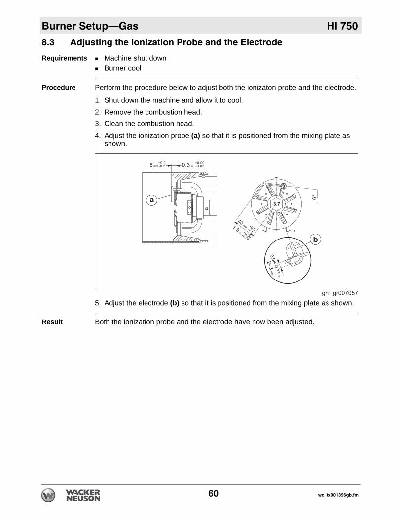
8.3 Adjusting the Ionization Probe and the ElectrodeRequirements Machine shut downBurner cool
Procedure Perform the procedure below to adjust both the ionizaton probe and the electrode.
1. Shut down the machine and allow it to cool.2. Remove the combustion head.3. Clean the combustion head.4. Adjust the ionization probe (a) so that it is positioned from the mixing plate as
shown.
5. Adjust the electrode (b) so that it is positioned from the mixing plate as shown.
Result Both the ionization probe and the electrode have now been adjusted.
60 wc_tx001396gb.fm
HI 750 Burner Setup—Gas
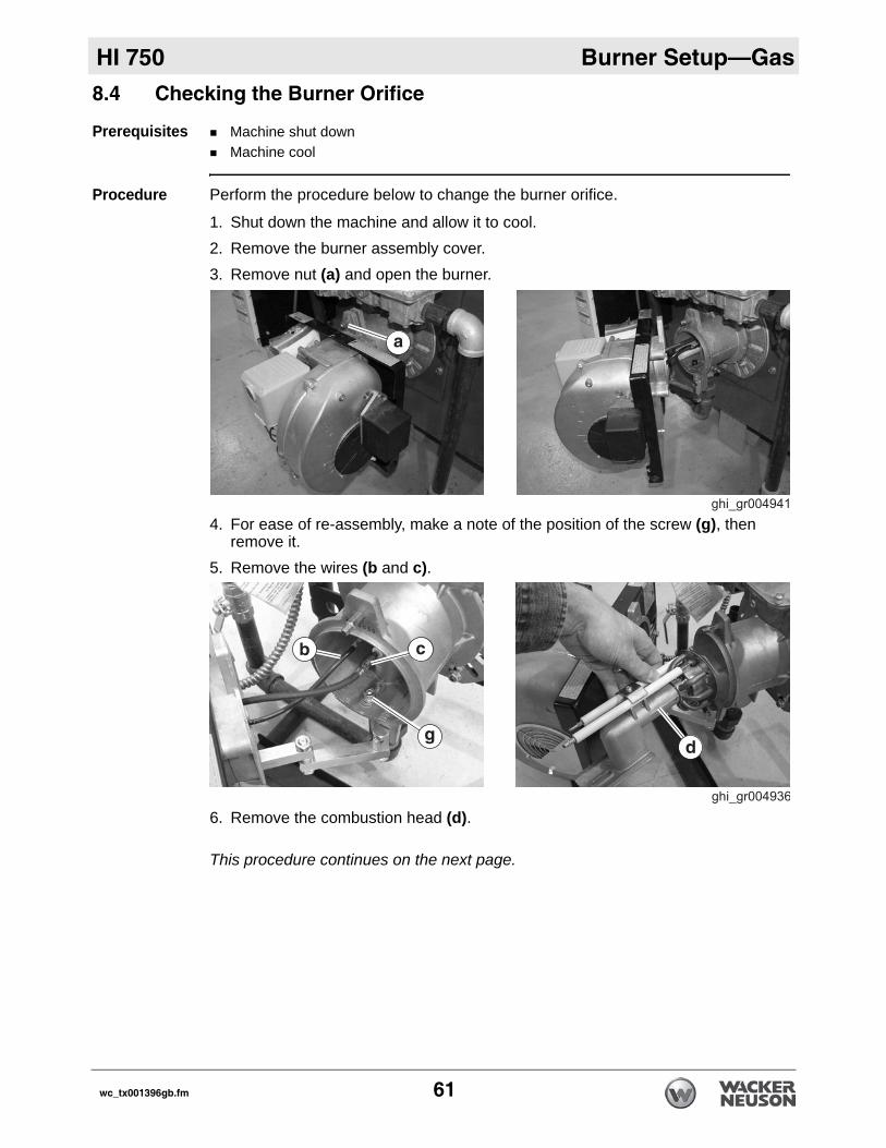
8.4 Checking the Burner OrificePrerequisites Machine shut downMachine cool
Procedure Perform the procedure below to change the burner orifice.
1. Shut down the machine and allow it to cool.2. Remove the burner assembly cover.3. Remove nut (a) and open the burner.
4. For ease of re-assembly, make a note of the position of the screw (g), then remove it.
5. Remove the wires (b and c).
6. Remove the combustion head (d).
This procedure continues on the next page.
wc_tx001396gb.fm 61
Burner Setup—Gas HI 750
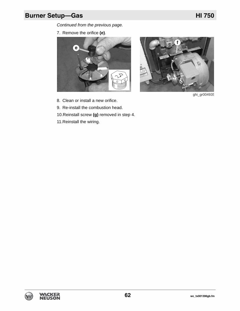
Continued from the previous page.7. Remove the orifice (e).
8. Clean or install a new orifice.9. Re-install the combustion head.10.Reinstall screw (g) removed in step 4.11.Reinstall the wiring.
ghi_gr004935
ef
62 wc_tx001396gb.fm
HI 750 Burner Setup—Gas
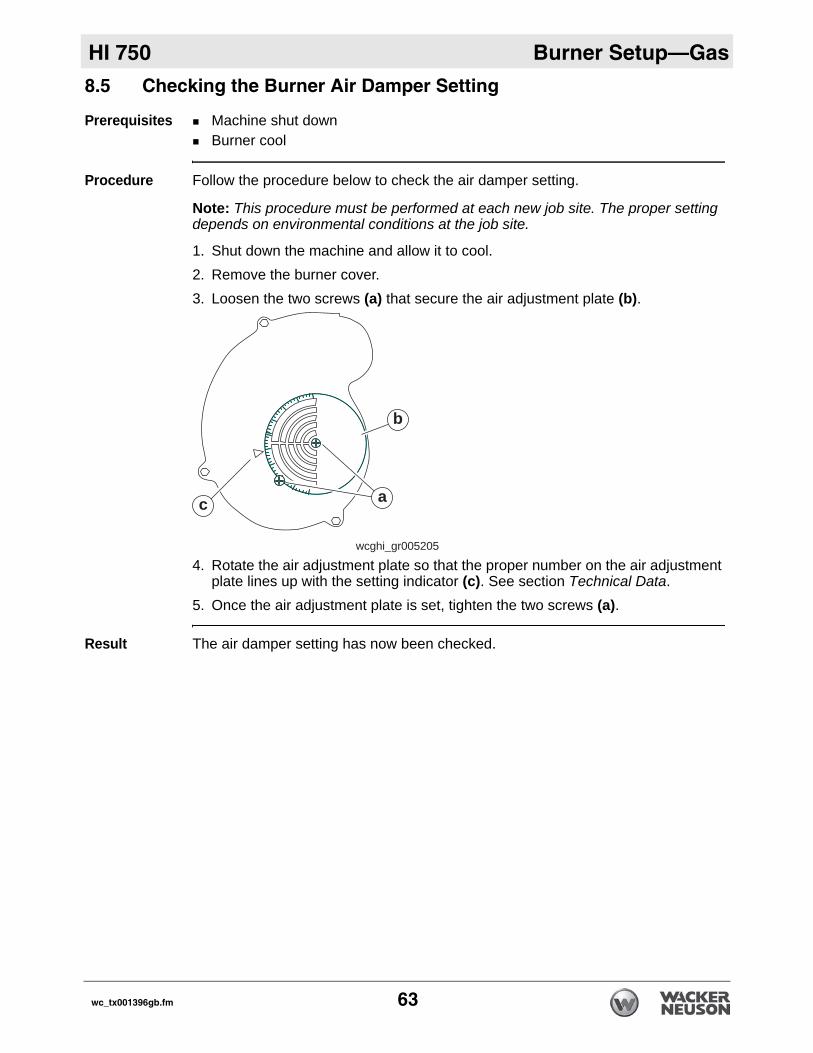
8.5 Checking the Burner Air Damper SettingPrerequisites Machine shut downBurner cool
Procedure Follow the procedure below to check the air damper setting.
Note: This procedure must be performed at each new job site. The proper setting depends on environmental conditions at the job site.
1. Shut down the machine and allow it to cool.2. Remove the burner cover.3. Loosen the two screws (a) that secure the air adjustment plate (b).
4. Rotate the air adjustment plate so that the proper number on the air adjustment plate lines up with the setting indicator (c). See section Technical Data.
5. Once the air adjustment plate is set, tighten the two screws (a).
Result The air damper setting has now been checked.
b
c a
wcghi_gr005205
wc_tx001396gb.fm 63
Burner Setup—Gas HI 750
8.6 Checking the Supply Gas PressureRequirements Machine shut downGas supply turned offManometerNipple
Checking pressure
Perform the procedure below to check and adjust the supply gas pressure.
1. Shut down the machine and allow it to cool.2. Close the gas supply shutoff valve.
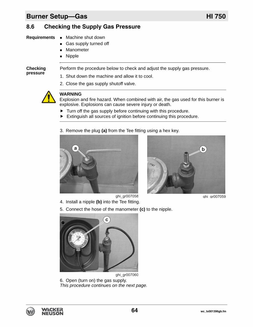
3. Remove the plug (a) from the Tee fitting using a hex key.
4. Install a nipple (b) into the Tee fitting.5. Connect the hose of the manometer (c) to the nipple.
6. Open (turn on) the gas supply.This procedure continues on the next page.
WARNINGExplosion and fire hazard. When combined with air, the gas used for this burner is explosive. Explosions can cause severe injury or death.
Turn off the gas supply before continuing with this procedure.Extinguish all sources of ignition before continuing this procedure.
64 wc_tx001396gb.fm
HI 750 Burner Setup—Gas
Continued from the previous page.7. Check the pressure reading on the manometer. See section Technical Data for the correct pressure. Adjust the gas supply pressure as needed.
8. After the gas supply pressure has been set, turn off the gas supply.9. Remove the manometer and the nipple.10.Reinstall the plug.
Result The gas supply pressure has now been checked and adjusted.
wc_tx001396gb.fm 65
Burner Setup—Gas HI 750
8.7 Checking and Adjusting the Burner Gas PressurePrerequisites Machine shut downBurner coolManometer
Checking pressure
Follow the procedure below to check and adjust the gas pressure.
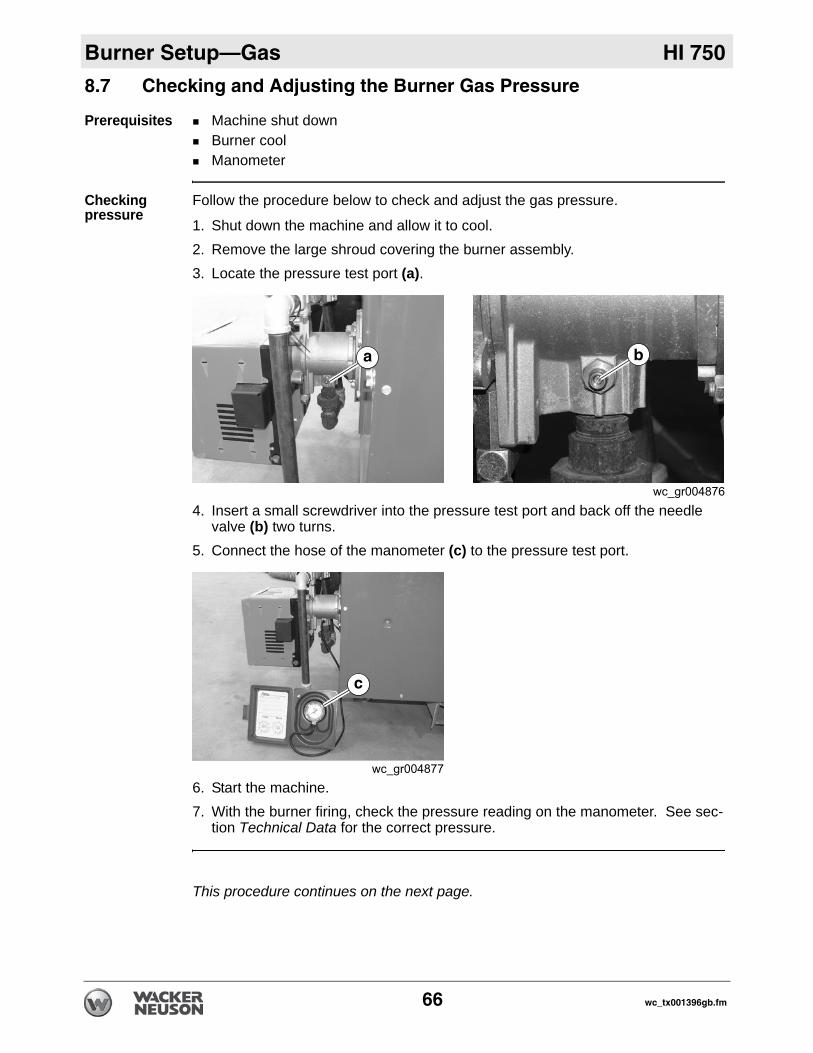
1. Shut down the machine and allow it to cool.2. Remove the large shroud covering the burner assembly.3. Locate the pressure test port (a).
4. Insert a small screwdriver into the pressure test port and back off the needle valve (b) two turns.
5. Connect the hose of the manometer (c) to the pressure test port.
6. Start the machine.7. With the burner firing, check the pressure reading on the manometer. See sec-
tion Technical Data for the correct pressure.
This procedure continues on the next page.
66 wc_tx001396gb.fm
HI 750 Burner Setup—Gas
Continued from the previous page.Adjusting pressure
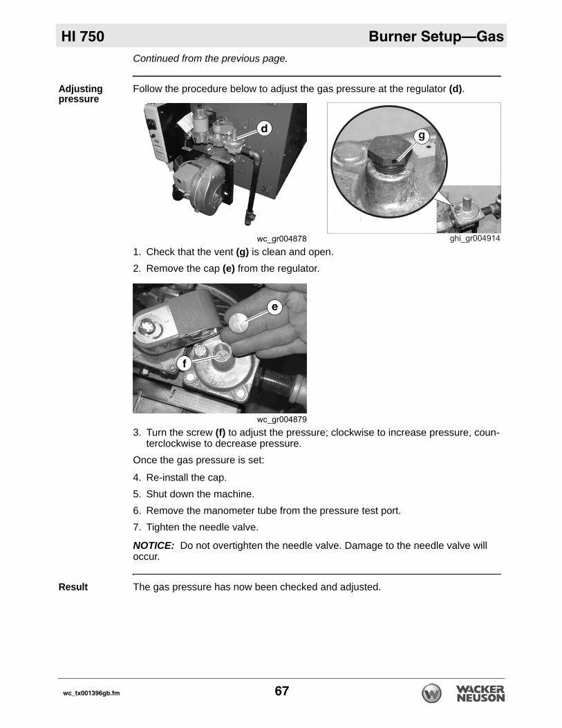
Follow the procedure below to adjust the gas pressure at the regulator (d).
1. Check that the vent (g) is clean and open.2. Remove the cap (e) from the regulator.
3. Turn the screw (f) to adjust the pressure; clockwise to increase pressure, coun-terclockwise to decrease pressure.
Once the gas pressure is set:
4. Re-install the cap.5. Shut down the machine.6. Remove the manometer tube from the pressure test port.7. Tighten the needle valve.
NOTICE: Do not overtighten the needle valve. Damage to the needle valve will occur.
Result The gas pressure has now been checked and adjusted.
wc_tx001396gb.fm 67
Burner Setup—Gas HI 750
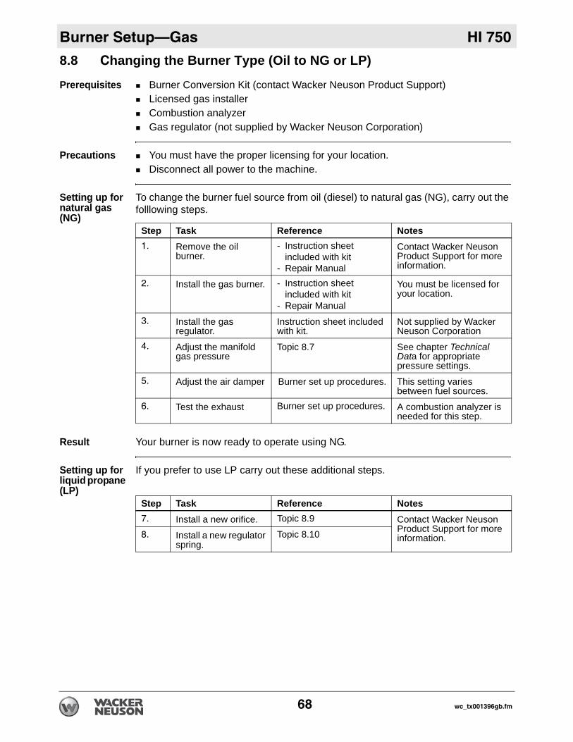
8.8 Changing the Burner Type (Oil to NG or LP)Prerequisites Burner Conversion Kit (contact Wacker Neuson Product Support)Licensed gas installerCombustion analyzerGas regulator (not supplied by Wacker Neuson Corporation)
Precautions You must have the proper licensing for your location.Disconnect all power to the machine.
Setting up for natural gas (NG)
To change the burner fuel source from oil (diesel) to natural gas (NG), carry out the folllowing steps.
Result Your burner is now ready to operate using NG.
Setting up for liquid propane (LP)
If you prefer to use LP carry out these additional steps.
Step Task Reference Notes1. Remove the oil
burner.- Instruction sheet
included with kit - Repair Manual
Contact Wacker Neuson Product Support for more information.
2. Install the gas burner. - Instruction sheet included with kit
- Repair Manual
You must be licensed for your location.
3. Install the gas regulator.
Instruction sheet included with kit.
Not supplied by Wacker Neuson Corporation
4. Adjust the manifold gas pressure
Topic 8.7 See chapter Technical Data for appropriate pressure settings.
5. Adjust the air damper Burner set up procedures. This setting varies between fuel sources.
6. Test the exhaust Burner set up procedures. A combustion analyzer is needed for this step.
Step Task Reference Notes7. Install a new orifice. Topic 8.9 Contact Wacker Neuson
Product Support for more information.8. Install a new regulator
spring.Topic 8.10
68 wc_tx001396gb.fm
HI 750 Burner Setup—Gas
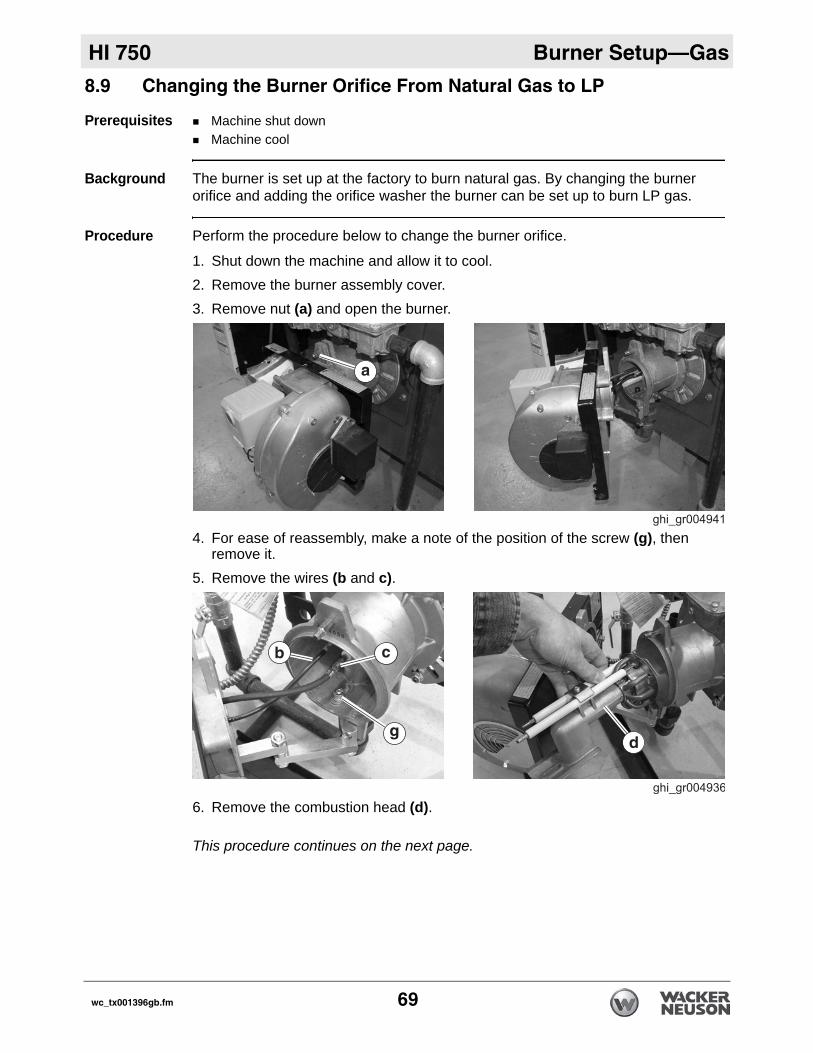
8.9 Changing the Burner Orifice From Natural Gas to LPPrerequisites Machine shut downMachine cool
Background The burner is set up at the factory to burn natural gas. By changing the burner orifice and adding the orifice washer the burner can be set up to burn LP gas.
Procedure Perform the procedure below to change the burner orifice.
1. Shut down the machine and allow it to cool.2. Remove the burner assembly cover.3. Remove nut (a) and open the burner.
4. For ease of reassembly, make a note of the position of the screw (g), then remove it.
5. Remove the wires (b and c).
6. Remove the combustion head (d).
This procedure continues on the next page.
wc_tx001396gb.fm 69
Burner Setup—Gas HI 750
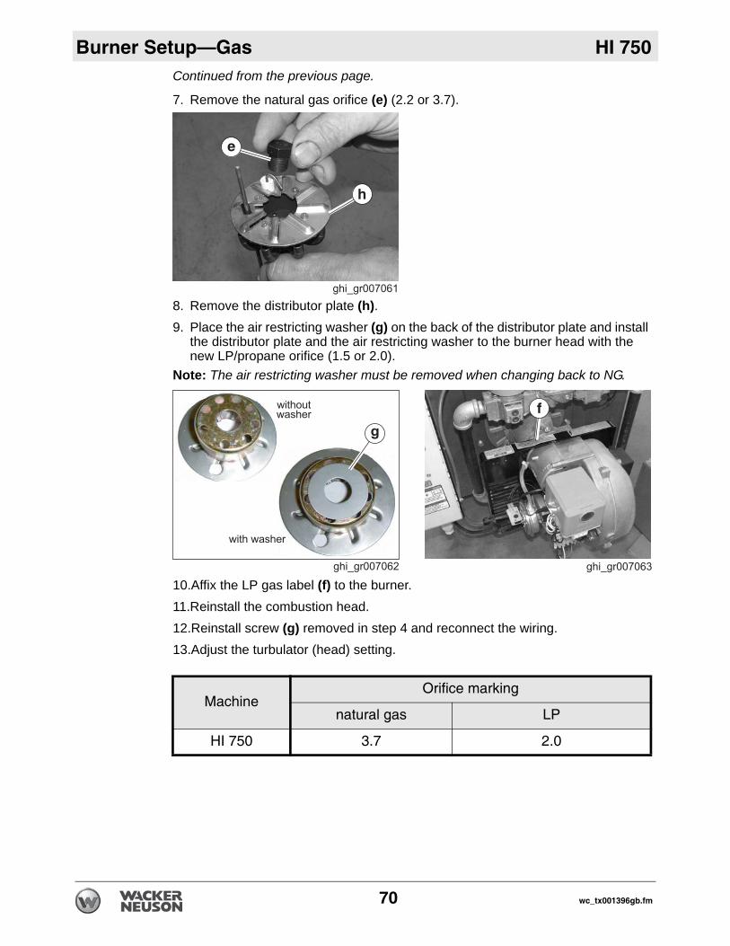
Continued from the previous page.7. Remove the natural gas orifice (e) (2.2 or 3.7).
8. Remove the distributor plate (h).9. Place the air restricting washer (g) on the back of the distributor plate and install
the distributor plate and the air restricting washer to the burner head with the new LP/propane orifice (1.5 or 2.0).
Note: The air restricting washer must be removed when changing back to NG.
10.Affix the LP gas label (f) to the burner.11.Reinstall the combustion head.12.Reinstall screw (g) removed in step 4 and reconnect the wiring.13.Adjust the turbulator (head) setting.
MachineOrifice marking
natural gas LP
HI 750 3.7 2.0
70 wc_tx001396gb.fm
HI 750 Burner Setup—Gas
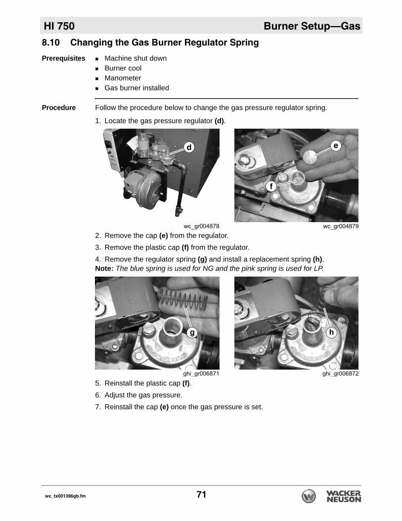
8.10 Changing the Gas Burner Regulator SpringPrerequisites Machine shut downBurner coolManometerGas burner installed
Procedure Follow the procedure below to change the gas pressure regulator spring.
1. Locate the gas pressure regulator (d)..
2. Remove the cap (e) from the regulator.3. Remove the plastic cap (f) from the regulator.4. Remove the regulator spring (g) and install a replacement spring (h).Note: The blue spring is used for NG and the pink spring is used for LP.
5. Reinstall the plastic cap (f). 6. Adjust the gas pressure. 7. Reinstall the cap (e) once the gas pressure is set.
wc_tx001396gb.fm 71
Maintenance HI 750
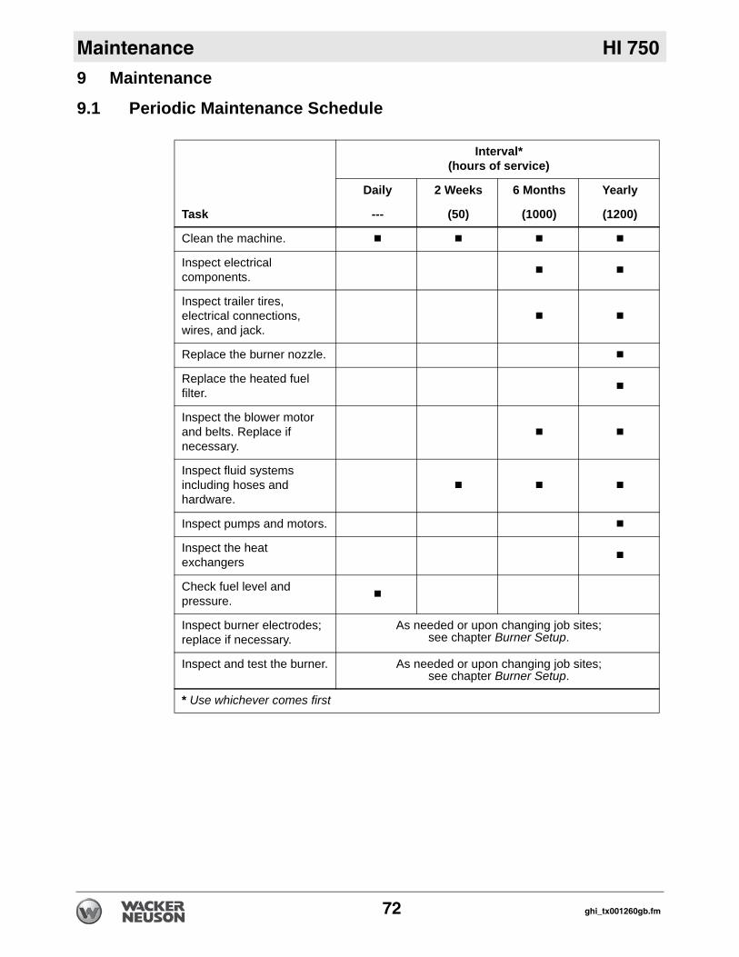
9 Maintenance9.1 Periodic Maintenance Schedule
Task
Interval*(hours of service)
Daily 2 Weeks 6 Months Yearly
--- (50) (1000) (1200)
Clean the machine.
Inspect electrical components.
Inspect trailer tires, electrical connections, wires, and jack.
Replace the burner nozzle.
Replace the heated fuel filter.
Inspect the blower motor and belts. Replace if necessary.
Inspect fluid systems including hoses and hardware.
Inspect pumps and motors.
Inspect the heat exchangers
Check fuel level and pressure.
Inspect burner electrodes; replace if necessary.
As needed or upon changing job sites;see chapter Burner Setup.
Inspect and test the burner. As needed or upon changing job sites;see chapter Burner Setup.
* Use whichever comes first
72 ghi_tx001260gb.fm
HI 750 Maintenance
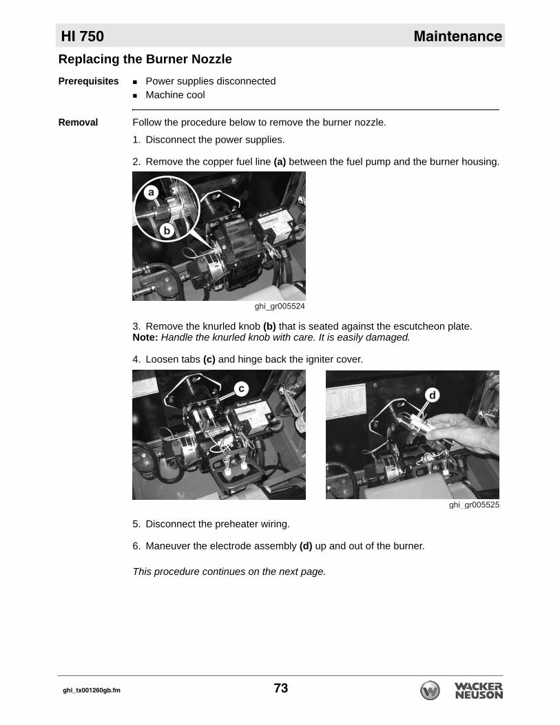
Replacing the Burner NozzlePrerequisites Power supplies disconnectedMachine cool
Removal Follow the procedure below to remove the burner nozzle.
1. Disconnect the power supplies.
2. Remove the copper fuel line (a) between the fuel pump and the burner housing.
3. Remove the knurled knob (b) that is seated against the escutcheon plate.Note: Handle the knurled knob with care. It is easily damaged.
4. Loosen tabs (c) and hinge back the igniter cover..
5. Disconnect the preheater wiring.
6. Maneuver the electrode assembly (d) up and out of the burner.
This procedure continues on the next page.
ghi_tx001260gb.fm 73
Maintenance HI 750
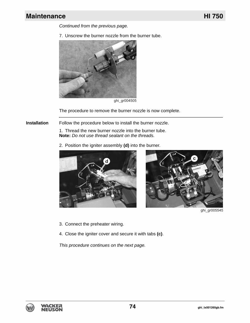
Continued from the previous page.7. Unscrew the burner nozzle from the burner tube.
The procedure to remove the burner nozzle is now complete.
Installation Follow the procedure below to install the burner nozzle.
1. Thread the new burner nozzle into the burner tube.Note: Do not use thread sealant on the threads.
2. Position the igniter assembly (d) into the burner.
3. Connect the preheater wiring.
4. Close the igniter cover and secure it with tabs (c).
This procedure continues on the next page.
74 ghi_tx001260gb.fm
HI 750 Maintenance
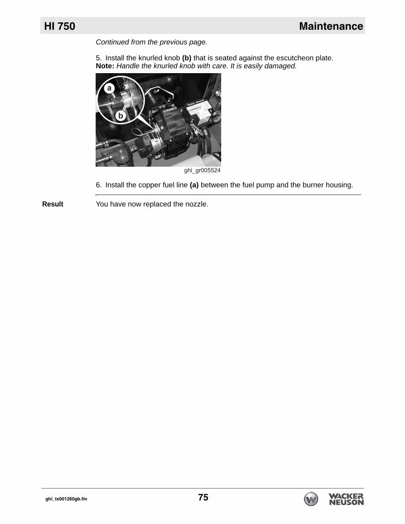
Continued from the previous page.5. Install the knurled knob (b) that is seated against the escutcheon plate.Note: Handle the knurled knob with care. It is easily damaged.
6. Install the copper fuel line (a) between the fuel pump and the burner housing.
Result You have now replaced the nozzle.
ghi_tx001260gb.fm 75
Maintenance HI 750
9.2 Replacing the Blower BeltPrerequisites Machine shut downBurner cool
Removal procedure
Follow the procedure below to remove the blower belt.
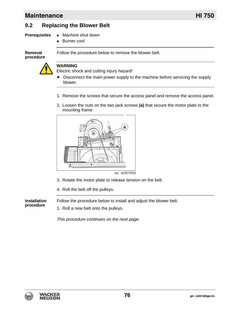
1. Remove the screws that secure the access panel and remove the access panel.
2. Loosen the nuts on the two jack screws (a) that secure the motor plate to the mounting frame.
3. Rotate the motor plate to release tension on the belt.
4. Roll the belt off the pulleys.
Installation procedure
Follow the procedure below to install and adjust the blower belt.
1. Roll a new belt onto the pulleys.
This procedure continues on the next page.
WARNINGElectric shock and cutting injury hazard!
Disconnect the main power supply to the machine before servicing the supply blower.
wc gr007659
a
76 ghi_tx001260gb.fm
HI 750 Maintenance
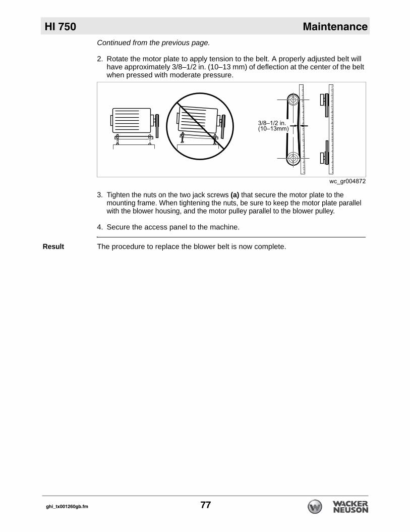
Continued from the previous page.2. Rotate the motor plate to apply tension to the belt. A properly adjusted belt will have approximately 3/8–1/2 in. (10–13 mm) of deflection at the center of the belt when pressed with moderate pressure.
3. Tighten the nuts on the two jack screws (a) that secure the motor plate to the mounting frame. When tightening the nuts, be sure to keep the motor plate parallel with the blower housing, and the motor pulley parallel to the blower pulley.
4. Secure the access panel to the machine.
Result The procedure to replace the blower belt is now complete.
ghi_tx001260gb.fm 77
Maintenance HI 750
9.3 Bleeding Air from the Generator Fuel System (if equipped)When Bleeding air from the generator fuel system is required:after the fuel filter and fuel lines have been detached and reinstalledafter the fuel tank has run drybefore starting the engine after long-term storage
Procedure Follow the procedure below to bleed air from the fuel system.
1. Fill the fuel tank completely.
2. Raise the front of the machine by fully extending the tongue jack.
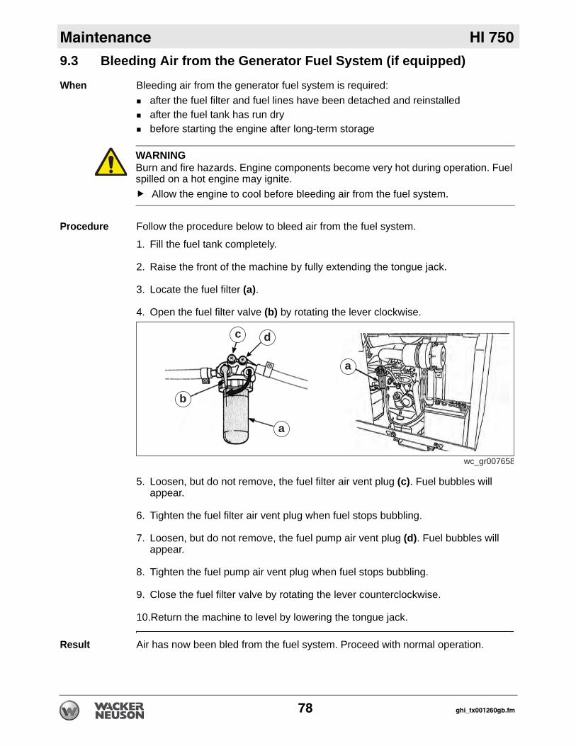
3. Locate the fuel filter (a).
4. Open the fuel filter valve (b) by rotating the lever clockwise.
5. Loosen, but do not remove, the fuel filter air vent plug (c). Fuel bubbles will appear.
6. Tighten the fuel filter air vent plug when fuel stops bubbling.
7. Loosen, but do not remove, the fuel pump air vent plug (d). Fuel bubbles will appear.
8. Tighten the fuel pump air vent plug when fuel stops bubbling.
9. Close the fuel filter valve by rotating the lever counterclockwise.
10.Return the machine to level by lowering the tongue jack.
Result Air has now been bled from the fuel system. Proceed with normal operation.
WARNINGBurn and fire hazards. Engine components become very hot during operation. Fuel spilled on a hot engine may ignite.
Allow the engine to cool before bleeding air from the fuel system.
wc_gr007658
a
dc
a
b
78 ghi_tx001260gb.fm
HI 750 Maintenance
9.4 General Cleaning GuidelinesPrerequisites Machine shut downMachine cool
General cleaning
Clean the following areas to ensure proper operation.
Item Method/taskBurner Remove all dirt and debris. Ensure air intake area is
unobstructed.Hoses, connectors, and couplings
Wipe clean with cloth.
Trailer (if equipped) Clean with compressed air: 50 PSI maximum.Covers/machine exterior
Wipe clean with cloth.
Air inlets/ouputs Remove all dirt and debris. Ensure air intake area is unobstructed.
ghi_tx001260gb.fm 79
Basic Troubleshooting HI 750
80 ghi_tx001262gb.fm
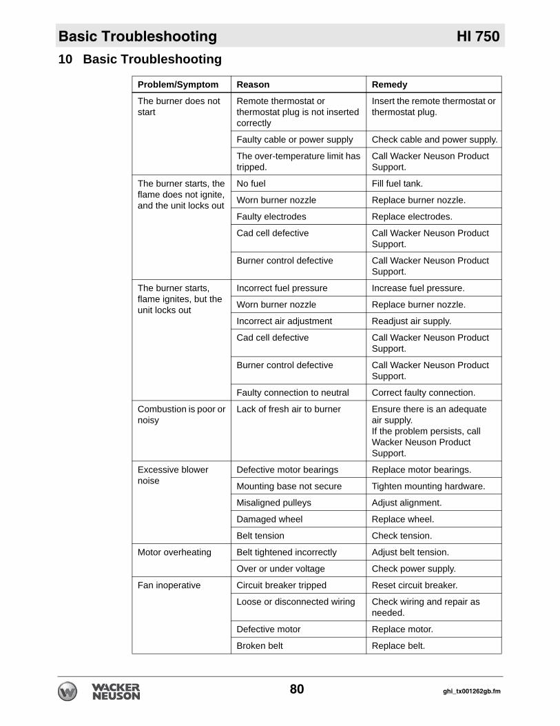
10 Basic Troubleshooting
Problem/Symptom Reason Remedy
The burner does not start
Remote thermostat or thermostat plug is not inserted correctly
Insert the remote thermostat or thermostat plug.
Faulty cable or power supply Check cable and power supply.
The over-temperature limit has tripped.
Call Wacker Neuson Product Support.
The burner starts, the flame does not ignite, and the unit locks out
No fuel Fill fuel tank.
Worn burner nozzle Replace burner nozzle.
Faulty electrodes Replace electrodes.
Cad cell defective Call Wacker Neuson Product Support.
Burner control defective Call Wacker Neuson Product Support.
The burner starts, flame ignites, but the unit locks out
Incorrect fuel pressure Increase fuel pressure.
Worn burner nozzle Replace burner nozzle.
Incorrect air adjustment Readjust air supply.
Cad cell defective Call Wacker Neuson Product Support.
Burner control defective Call Wacker Neuson Product Support.
Faulty connection to neutral Correct faulty connection.
Combustion is poor or noisy
Lack of fresh air to burner Ensure there is an adequate air supply.If the problem persists, call Wacker Neuson Product Support.
Excessive blower noise
Defective motor bearings Replace motor bearings.
Mounting base not secure Tighten mounting hardware.
Misaligned pulleys Adjust alignment.
Damaged wheel Replace wheel.
Belt tension Check tension.
Motor overheating Belt tightened incorrectly Adjust belt tension.
Over or under voltage Check power supply.
Fan inoperative Circuit breaker tripped Reset circuit breaker.
Loose or disconnected wiring Check wiring and repair as needed.
Defective motor Replace motor.
Broken belt Replace belt.
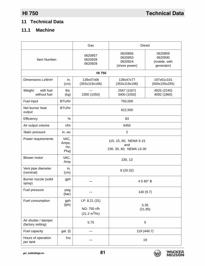
HI 750 Technical Data
11 Technical Data11.1 Machine
Gas Diesel
Item Number:062085706209280620929
062085606209530620924
(shore power)
06208590620930
(mobile, with generator)
HI 750
Dimensions LxWxH in.(cm)
139x47x66(353x119x166)
139x47x77(353x119x196)
197x61x101(500x155x255)
Weight: with fuel without fuel
lbs.(kg)
—2300 (1050)
2567 (1167)3400 (1550)
4925 (2240)4092 (1860)
Fuel input BTU/hr 750,000
Net burner heat output
BTU/hr 622,500
Efficiency % 83
Air output volume cfm 6450
Static pressure in. wc 2
Power requirements VAC,Amps,
Hz;Plug
115, 15, 60; NEMA 5-15and
230, 30, 60; NEMA L6-30
Blower motor VAC,Amp 230, 13
Vent pipe diameter (nominal)
in.(cm) 8 (20.32)
Burner nozzle (solid spray)
gph — 4.5 60° B
Fuel pressure psig(bar) — 140 (9.7)
Fuel consumption gph(lph)
LP: 8.21 (31)
NG: 750 cfh (21.2 m3/hr)
5.35(21.85)
Air shutter / damper(factory setting) 5.75 5
Fuel capacity gal. (l) — 119 (449.7)
Hours of operation per tank
hrs — 19
ghi_tx000360gb.fm 81
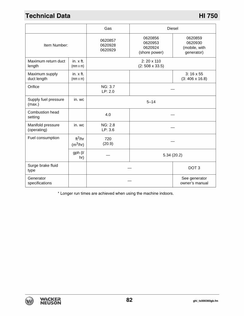
Technical Data HI 750
* Longer run times are achieved when using the machine indoors.
Maximum return duct length
in. x ft.(mm x m)
2: 20 x 110(2: 508 x 33.5)
Maximum supply duct length
in. x ft.(mm x m)
3: 16 x 55(3: 406 x 16.8)
Orifice NG: 3.7LP: 2.0 —
Supply fuel pressure (max.)
in. wc 5–14
Combustion head setting 4.0 —
Manifold pressure (operating)
in. wc NG: 2.8LP: 3.6 —
Fuel consumption ft3/hr(m3/hr)
720 (20.9) —
gph (l/hr) — 5.34 (20.2)
Surge brake fluid type — DOT 3
Generatorspecifications — See generator
owner’s manual
Gas Diesel
Item Number:062085706209280620929
062085606209530620924
(shore power)
06208590620930
(mobile, with generator)
82 ghi_tx000360gb.fm
HI 750
Schematics84
12 Schematics
This page is intentionally left blank.
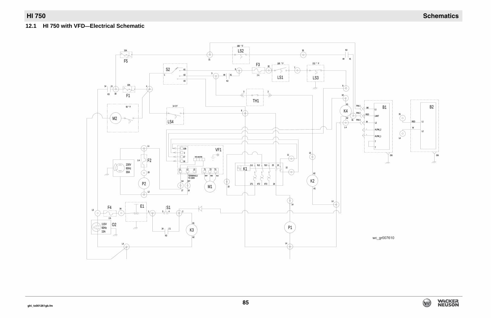
Schematics
22
L4L4
L4L4
1313
K2K2
A2A2
A1A1
6T36T3
2323 1313
2424
5L35L3
1414
1212
1111
P1P1
GNGN
PIN 3PIN 3
PIN 2PIN 2
PIN 1PIN 1
--
WW
REDRED
BKBK
TT
TT
ALRM_1ALRM_1
ALRM_2ALRM_2
L2L2
LIMITLIMIT
L1L1
--
1010
99
77
185185 °° F F 212212 °° F F
LL 44
3131
41414444
K4K43333
3232
A1A1
A2A2
LS3LS3LS1LS1
K4K4B1B1 B2B2
L4L4
3131
WW
REDRED
L2L2
L1L1
GNGN
HI 750
ghi_tx001261gb.fm 85
12.1 HI 750 with VFD—Electrical Schematic
88
33
K3K3O2O2115V115V
60Hz60Hz15A15A
L4L4
A1A1
A2A2
11
22 11
K3K3
2424
2244S1S1E1E1
33L3L3
16161717
1616
1717
22
13B13B
TERMINALSTERMINALSTO 230VTO 230V
M1M1
VF1VF1VFD HEATERVFD HEATER
WHTWHTBLKBLK
11 A A
L1L1
F2F2
L2L2
P2P2
230V230V60Hz60Hz30A30A
L1L1 L3L3L2L2 T1T1
BLKBLK
T3T3
REDRED
T2T2
WHTWHT
K1K13L23L21L11L1
4T24T22T12T11515
M2M2
1414 1111
F1F1K3K3
4410A10A
S2S2
A3A3
A2A2
A1A1
11 4444 4141
K2K2
55
2121
66
2 A 2 A
3030
1414 0 F 0 F
15A15A
180180 °° F F
5050 °° F F
F4F4
F5F5
3434
2020
22 A A
F3F3
LS4LS4
LS2LS2
TH1TH1

HI 750
lors
YL Yellow OR Orange
BR Brown PU Purple
CL Clear SH Shield
GY Gray LB Lt. blue
Schematics
86
12.2 HI 750 with VFD—Electrical Schematic Components
Ref. Description Ref. DescriptionB1 Beckett oil burner LS2 High limit switchB2 Riello gas burner LS3 High limit switch 2E1 Emergency stop switch LS4 Fan limit switchF1 Burner circuit breaker M1 Blower motorF2 Fuse, 1A M2 Control panel fanF3 Fuse, 2A O1 Customer connection, 230VF4 Fuse, 2A O2 Customer connection, 115VF5 Magnetic circuit breaker P1 Hour meterK1 Motor contactor P2 VoltmeterK2 Remote thermostat relay S1 Start switchK3 Emergency stop relay S2 Operator switchK4 Burner relay TH1 Remote thermostat
LS1 Burner limit switch VF1 Variable frequency drive (if equipped)
Wire Co
BK Black RD Red
GN Green TN Tan
BU Blue VIO Violet
PK Pink WH White
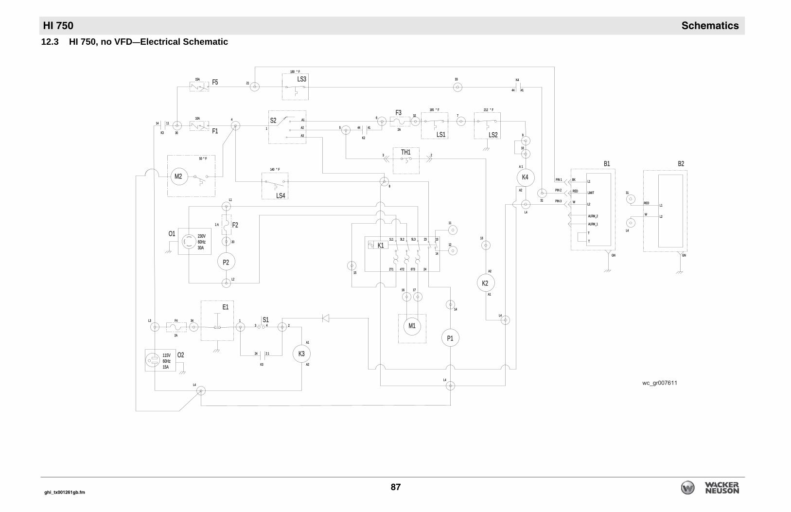
Schematics
L4L4
1313
K2K2
1111
1212
L4L4
1414
P1P1
2424
1414
13132323
A2A2
A1A1
L4L4
3131
WW
REDRED
L2L2
L1L1
GNGNGNGN
PIN 3PIN 3
PIN 2PIN 2
PIN 1PIN 1
WW
REDRED
BKBK
TT
TT
ALRM_1ALRM_1
ALRM_2ALRM_2
L2L2
LIMITLIMIT
L1L1
1010
99
22
77185185 °° FF 212212 °° FF
L4L4
3131
K4K4
41414444
3333
AA 11
A2A2
LS1LS1 LS2LS2
K4K4
B1B1 B2B2
HI 750
ghi_tx001261gb.fm 87
12.3 HI 750, no VFD—Electrical Schematic
88
1616 1717
M1M1
15152T12T1 4T24T2 6T36T3
1L11L1 3L23L2 5L35L3
K1K1
A2A2
A1A1
2424
44
22 11
33S1S1
O2O2
O1O1
E1E1
L4L4
115V115V60Hz60Hz15A15A
L3L322
11
K3K3
K3K3
11 A A
L1L1
L2L2
230V230V60Hz60Hz30A30A
2020
P2P2
F2F2
M2M2
4444 4141
S2S2
A3A3
A2A2
A1A1
11
33
66
K2K2
55
10A10A 44
F1F1K3K3
11111414
15A15A
3030
2121
180180 °° FF
2A2A
F4F4
5050 °° FF
140140 °° FF
2A2A
F5F5
3434
3232F3F3
TH1TH1
LS3LS3
LS4LS4
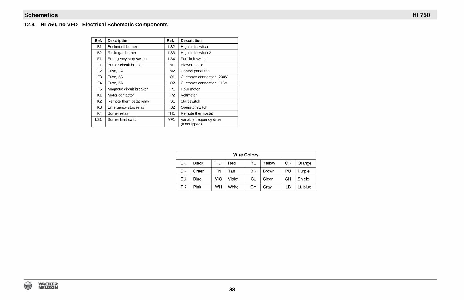
HI 750
lors
YL Yellow OR Orange
BR Brown PU Purple
CL Clear SH Shield
GY Gray LB Lt. blue
Schematics
88
12.4 HI 750, no VFD—Electrical Schematic Components
Ref. Description Ref. DescriptionB1 Beckett oil burner LS2 High limit switchB2 Riello gas burner LS3 High limit switch 2E1 Emergency stop switch LS4 Fan limit switchF1 Burner circuit breaker M1 Blower motorF2 Fuse, 1A M2 Control panel fanF3 Fuse, 2A O1 Customer connection, 230VF4 Fuse, 2A O2 Customer connection, 115VF5 Magnetic circuit breaker P1 Hour meterK1 Motor contactor P2 VoltmeterK2 Remote thermostat relay S1 Start switchK3 Emergency stop relay S2 Operator switchK4 Burner relay TH1 Remote thermostat
LS1 Burner limit switch VF1 Variable frequency drive (if equipped)
Wire Co
BK Black RD Red
GN Green TN Tan
BU Blue VIO Violet
PK Pink WH White
Schematics
HI 750ghi_tx001261gb.fm 89


Wacker Neuson SE · Preußenstraße 41 · D-80809 München · Tel.: +49-(0)89-3 54 02-0 · Fax: +49 - (0)89-3 54 02-390Wacker Neuson Corporation · N92W15000 Anthony Ave. · Menomonee Falls, WI 53051 · Tel. : (262) 255-0500 · Fax: (262) 255-0550 ·Tel. : (800) 770-0957Wacker Neuson Limited - Room 1701–03 & 1717–20, 17/F. Tower 1, Grand Century Place, 193 Prince Edward Road West, Mongkok, Kowloon, Hongkong.Tel: (852) 3605 5360, Fax: (852) 2758 0032