Embed Size (px)
Citation preview
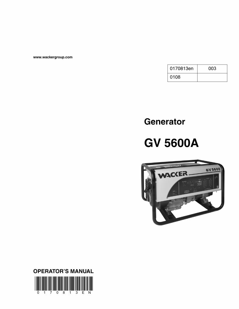
www.wackergroup.com
Generator
GV 5600A
OPERATOR’S MANUAL
0170813en 003
0108
0 1 7 0 8 1 3 E N

DANGER
CARBON MONOXIDEUsing a generator indoors CAN KILL YOU IN MINUTES.
Generator exhaust contains carbon monoxide (CO). This is a poison you cannot see or smell. If you can smell the generator exhaust, you are breathing CO. But even if you cannot smell the exhaust, you could be breathing CO.
• NEVER use a generator inside homes, garages, crawlspaces, or other partly enclosed areas. Deadly levels of carbon monoxide can build up in these areas. Using a fan or opening windows and doors does NOT supply enough fresh air.
• ONLY use a generator outside and far away from windows, doors, and vents. These openings can pull in generator exhaust.
Even when you use a generator correctly, CO may leak into the home. ALWAYS use a battery-powered or battery-backup CO alarm in the home.
If you start to feel sick, dizzy, or weak after the generator has been running, move to fresh air RIGHT AWAY. See a doctor. You could have carbon monoxide poison.
GV 5600A Table of Contents
wc_bo0170813en_003TOC.fm 3
1. Foreword 5
2. Safety Information 6
2.1 Laws Pertaining to Spark Arresters ...................................................... 62.2 Operating Safety .................................................................................. 72.3 Operator Safety while using Internal Combustion Engines .................. 92.4 Service Safety .................................................................................... 102.5 Label Locations .................................................................................. 112.6 Safety and Operating Labels .............................................................. 12
3. Operation 15
3.1 Determining Power Requirements ..................................................... 153.2 Installation .......................................................................................... 163.3 Installing Spark Arrester ..................................................................... 163.4 Generator Derating ............................................................................. 173.5 Grounding the Generator ................................................................... 183.6 Operating Heavy Loads ...................................................................... 183.7 Use of Extension Cords ...................................................................... 193.8 Control Panel ...................................................................................... 203.9 Ground Fault Interrupt (GFI) ............................................................... 213.10 Main Circuit Breaker ........................................................................... 213.11 Voltage Selection ............................................................................... 223.12 Engine Auto Idle ................................................................................. 223.13 Before Starting ................................................................................... 233.14 To Start ............................................................................................... 243.15 To Stop ............................................................................................... 25
Table of Contents GV 5600A
wc_bo0170813en_003TOC.fm 4
4. Maintenance 26
4.1 Engine Maintenance ............................................................................264.2 Periodic Maintenance Schedule ..........................................................264.3 Engine Oil ............................................................................................274.4 Servicing Air Cleaner ...........................................................................284.5 Spark Plug ...........................................................................................294.6 Cleaning the Sediment Cup ................................................................304.7 Storage ................................................................................................314.8 Transport .............................................................................................324.9 Troubleshooting ...................................................................................33
5. Technical Data 34
5.1 Generator ............................................................................................345.2 Engine .................................................................................................355.3 Electrical Schematic ............................................................................365.4 Schematic Components ......................................................................37
wc_tx000001gb.fm 5
CALIFORNIA
Proposition 65 Warning:
Engine exhaust, some of its constituents, and certain vehiclecomponents, contain or emit chemicals known to the State ofCalifornia to cause cancer and birth defects or other reproductiveharm.
1. Foreword
This manual provides information and procedures to safely operateand maintain this Wacker model. For your own safety and protectionfrom injury, carefully read, understand and observe the safetyinstructions described in this manual.
Keep this manual or a copy of it with the machine. If you lose thismanual or need an additional copy, please contact WackerCorporation. This machine is built with user safety in mind; however,it can present hazards if improperly operated and serviced. Followoperating instructions carefully! If you have questions about operatingor servicing this equipment, please contact Wacker Corporation.
The information contained in this manual was based on machines inproduction at the time of publication. Wacker Corporation reserves theright to change any portion of this information without notice.
All rights, especially copying and distribution rights, are reserved.
Copyright 2007 by Wacker Corporation.
No part of this publication may be reproduced in any form or by anymeans, electronic or mechanical, including photocopying, withoutexpress written permission from Wacker Corporation.
Any type of reproduction or distribution not authorized by WackerCorporation represents an infringement of valid copyrights and will beprosecuted. We expressly reserve the right to make technicalmodifications, even without due notice, which aim at improving ourmachines or their safety standards.
WARNING
Safety Information GV 5600A
wc_si000208gb.fm 6
2. Safety Information
This manual contains DANGER, WARNING, CAUTION, NOTICE andNOTE callouts which must be followed to reduce the possibility ofpersonal injury, damage to the equipment, or improper service.
This is the safety alert symbol. It is used to alert you to potentialpersonal injury hazards. Obey all safety messages that follow thissymbol to avoid possible injury or death.
DANGER indicates a hazardous situation which, if not avoided, willresult in death or serious injury.
WARNING indicates a hazardous situation which, if not avoided, couldresult in death or serious injury.
CAUTION indicates a hazardous situation which, if not avoided, couldresult in minor or moderate injury.
NOTICE: Used without the safety alert symbol, NOTICE indicates ahazardous situation which, if not avoided, could result in propertydamage.
Note: Contains additional information important to a procedure.
2.1 Laws Pertaining to Spark Arresters
Notice: State Health Safety Codes and Public Resources Codesspecify that in certain locations spark arresters be used on internalcombustion engines that use hydrocarbon fuels. A spark arrester is adevice designed to prevent accidental discharge of sparks or flamesfrom the engine exhaust. Spark arresters are qualified and rated bythe United States Forest Service for this purpose.
In order to comply with local laws regarding spark arresters, consultthe engine distributor or the local Health and Safety Administrator.
DANGER
WARNING
CAUTION
GV 5600A Safety Information
wc_si000208gb.fm 7
2.2 Operating Safety
Using a generator indoors CAN KILL YOU IN MINUTES. Generatorexhaust contains carbon monoxide. This is a poison you cannot see orsmell. NEVER use this generator inside a home or garage, EVEN IFdoors and windows are open. Only use this generator OUTSIDE andfar away from windows, doors, and vents.
BACKFEED FROM THE GENERATOR INTO THE PUBLIC POWERDISTRIBUTION SYSTEM CAN CAUSE SERIOUS INJURY ORDEATH TO UTILITY WORKERS!
Improper connection of generator to a building’s electrical system canallow electrical current from the generator to backfeed into utility lines.This may result in electrocution of utility workers, fire, or explosion.Connections to a building’s electrical system must be made by aqualified electrician and comply with all applicable laws and electricalcodes.
If connected to a building’s electrical system the generator must meetthe power, voltage, and frequency requirements of the equipment inthe building. Differences in power, voltage, and frequencyrequirements may exist and improper connection may lead toequipment damage, fire, and personal injury or death.
Familiarity and proper training are required for the safe operation of themachine. Machines operated improperly or by untrained personnelcan be dangerous. Read the operating instructions contained in boththis manual and the engine manual and familiarize yourself with thelocation and proper use of all controls. Inexperienced operators shouldreceive instruction from someone familiar with the machine beforebeing allowed to operate it.
2.2.1 NEVER operate the generator when open containers of fuel, paint, orother flammable liquids are near.
2.2.2 NEVER operate the generator, or tools attached to the generator, withwet hands.
2.2.3 NEVER use worn electrical cords. Severe electrical shock andequipment damage may result.
2.2.4 NEVER run the electrical cords under the generator, or over vibratingor hot parts.
2.2.5 NEVER enclose or cover the generator when it is in use or when it ishot.
2.2.6 NEVER overload the generator. The total amperage of the tools andequipment attached to the generator must not exceed the load ratingof the generator.
DANGER
DANGER
WARNING
Safety Information GV 5600A
wc_si000208gb.fm 8
2.2.7 NEVER operate the machine in snow, rain, or standing water.
2.2.8 NEVER allow untrained personnel to operate or service the generator.The generator set should be set up by a trained electrician.
2.2.9 NEVER stand on the machine.
2.2.10 DO NOT stand under the machine while it is being hoisted or moved.
2.2.11 DO NOT attach equipment to the machine when it is suspended.
2.2.12 ALWAYS store the equipment properly when it is not being used.Equipment should be stored in a clean, dry location out of the reach ofchildren.
2.2.13 ALWAYS position and operate the generator on a firm,noncombustible, level surface.
2.2.14 ALWAYS transport the generator in an upright position.
2.2.15 ALWAYS keep the machine far away from structures, buildings, andother equipment during use.
2.2.16 ALWAYS keep the area immediately surrounding and underneath themachine clean, neat, and free of debris and combustible materials.Make sure that the area overhead is clear of debris that could fall ontoor into the machine or exhaust compartment.
2.2.17 ALWAYS remove all tools, cords, and other loose items from thegenerator before starting it.
2.2.18 ALWAYS make certain the machine is well-grounded and securelyfastened to a good earthen ground per national and local regulations.
GV 5600A Safety Information
wc_si000208gb.fm 9
2.3 Operator Safety while using Internal Combustion Engines
Internal combustion engines present special hazards during operationand fueling. Read and follow the warning instructions in the engineowner’s manual and the safety guidelines below. Failure to follow thewarnings and safety guidelines could result in severe injury or death.
2.3.1 NEVER use this generator inside a home or garage, EVEN IF doorsand windows are open. Only use OUTSIDE and far away fromwindows, doors, and vents. Using a generator indoors CAN KILL YOUIN MINUTES. Generator exhaust contains carbon monoxide. This is apoison you cannot see or smell.
2.3.2 NEVER use a generator inside an enclosed area such as a tunnel or atrench.
2.3.3 DO NOT smoke while operating the machine.
2.3.4 DO NOT smoke when refueling the engine.
2.3.5 DO NOT refuel a hot or running engine.
2.3.6 DO NOT refuel the engine near an open flame.
2.3.7 DO NOT spill fuel when refueling the engine.
2.3.8 DO NOT run the engine near open flames.
2.3.9 DO NOT start the engine if fuel has spilled or a fuel odor is present.Move the generator away from the spill and wipe the generator drybefore starting.
2.3.10 ALWAYS refill the fuel tank in a well-ventilated area.
2.3.11 ALWAYS replace the fuel tank cap after refueling.
2.3.12 ALWAYS check the fuel lines and the fuel tank for leaks and cracksbefore starting the engine. Do not run the machine if fuel leaks arepresent or the fuel lines are loose.
DANGER
Safety Information GV 5600A
wc_si000208gb.fm 10
2.4 Service Safety
Poorly maintained equipment can become a safety hazard! In orderfor the equipment to operate safely and properly over a long period oftime, periodic maintenance and occasional repairs are necessary. Ifthe generator is experiencing problems or is being serviced, attach a“DO NOT START” sign to the control panel to notify other people of itscondition.
2.4.1 DO NOT use gasoline or other types of fuels or flammable solvents toclean parts, especially in enclosed areas. Fumes from fuels andsolvents can become explosive.
2.4.2 DO NOT attempt to clean or service the machine while it is running.
2.4.3 DO NOT modify the machine without the express written approval ofthe manufacturer.
2.4.4 DO NOT allow water to accumulate around the base of the machine.If water is present, move the machine and allow the machine to drybefore servicing.
2.4.5 DO NOT service the machine if your clothing or skin is wet.
2.4.6 DO NOT allow untrained personnel to service this equipment. Onlytrained electrical technicians should be allowed to service the electricalcomponents of this equipment.
2.4.7 ALWAYS keep the machine clean and labels legible. Replace allmissing and hard-to-read labels. Labels provide important operatinginstructions and warn of dangers and hazards.
2.4.8 ALWAYS replace the safety devices and guards after repairs andmaintenance.
2.4.9 ALWAYS let the engine cool before transporting or servicing it.
2.4.10 ALWAYS keep hands, feet, and loose clothing away from the movingparts on the generator and engine.
2.4.11 ALWAYS turn the engine off before servicing the machine. If theengine has electric start, disconnect the negative terminal on thebattery before servicing the machine.
2.4.12 ALWAYS keep the fuel lines in good condition and properly connected.Leaking fuel and fumes are extremely explosive.
WARNING
GV 5600A Safety Information
wc_si000208gb.fm 11
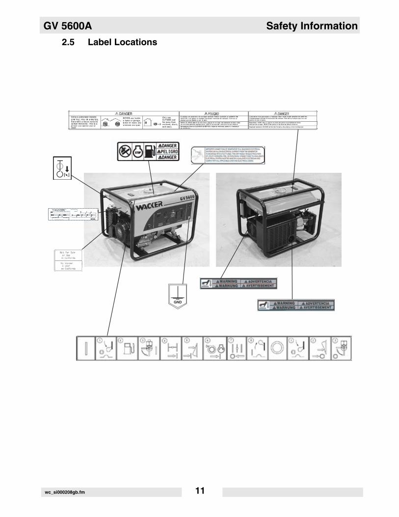
2.5 Label Locations
Safety Information GV 5600A
wc_si000208gb.fm 12
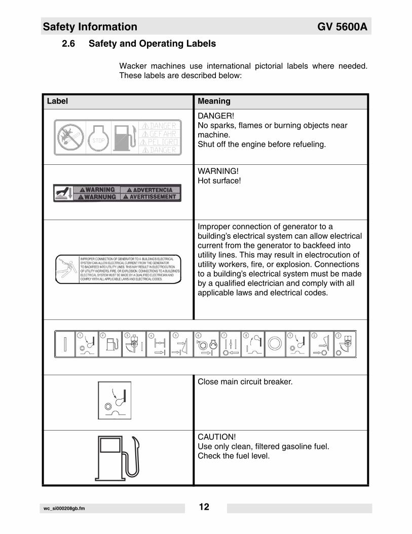
2.6 Safety and Operating Labels
Wacker machines use international pictorial labels where needed.These labels are described below:
Label Meaning
DANGER!No sparks, flames or burning objects near machine.Shut off the engine before refueling.
WARNING! Hot surface!
Improper connection of generator to a building’s electrical system can allow electrical current from the generator to backfeed into utility lines. This may result in electrocution of utility workers, fire, or explosion. Connections to a building’s electrical system must be made by a qualified electrician and comply with all applicable laws and electrical codes.
Close main circuit breaker.
CAUTION! Use only clean, filtered gasoline fuel.Check the fuel level.
GV 5600A Safety Information
wc_si000208gb.fm 13
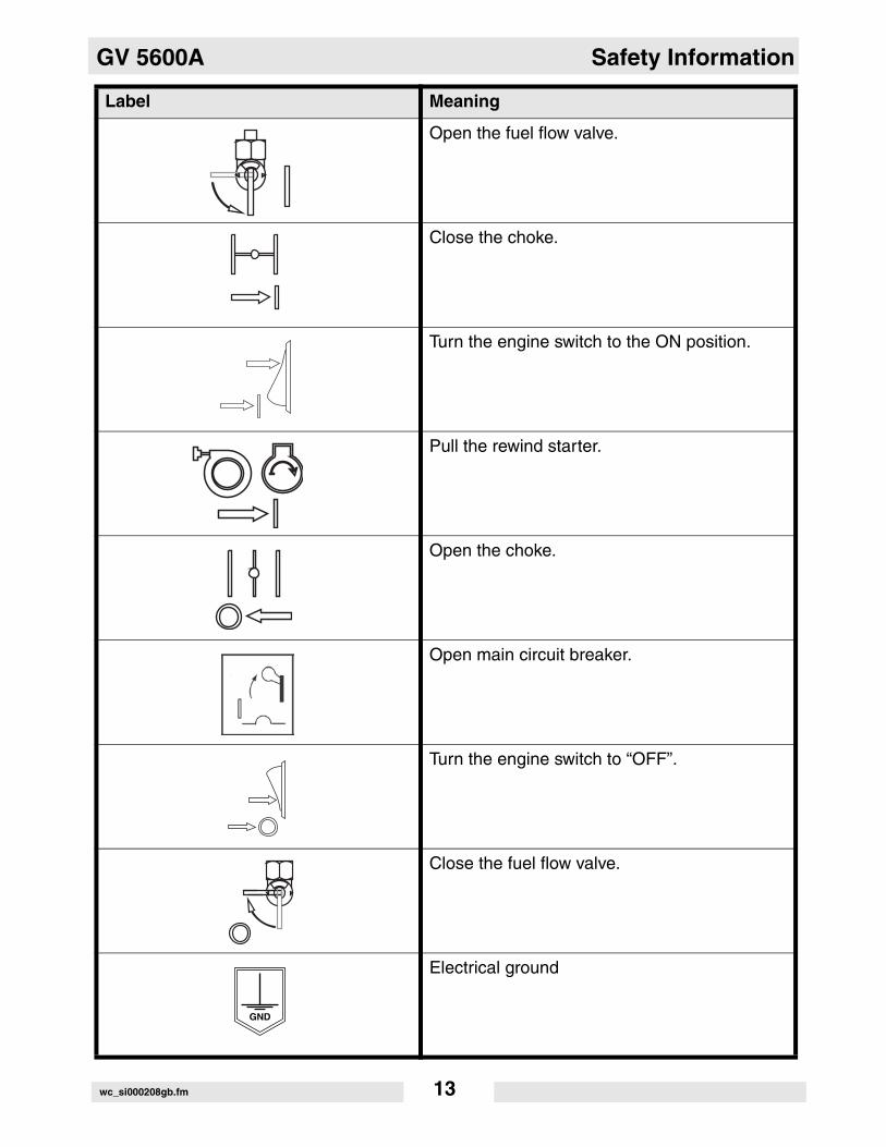
Open the fuel flow valve.
Close the choke.
Turn the engine switch to the ON position.
Pull the rewind starter.
Open the choke.
Open main circuit breaker.
Turn the engine switch to “OFF”.
Close the fuel flow valve.
Electrical ground
Label Meaning
Safety Information GV 5600A
wc_si000208gb.fm 14
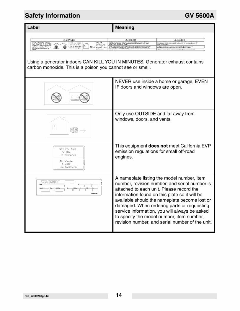
Using a generator indoors CAN KILL YOU IN MINUTES. Generator exhaust contains carbon monoxide. This is a poison you cannot see or smell.
NEVER use inside a home or garage, EVEN IF doors and windows are open.
Only use OUTSIDE and far away from windows, doors, and vents.
This equipment does not meet California EVP emission regulations for small off-road engines.
A nameplate listing the model number, item number, revision number, and serial number is attached to each unit. Please record the information found on this plate so it will be available should the nameplate become lost or damaged. When ordering parts or requesting service information, you will always be asked to specify the model number, item number, revision number, and serial number of the unit.
Label Meaning
A
MADE IN USAMADE IN USA
ModelModel
Item No.Item No. Rev.Rev. Serial No.Serial No.
kgkg V
kW MaxkW Maxlbslbs Ø P.F.P.F.
1643
2916
4329
hzhz
GV 5600A Operation
15
3. Operation
3.1 Determining Power Requirements
This generator is designed to operate single-phase, 60 Hz appliancesrunning at 120 VAC. Check the nameplate or label provided on toolsand appliances to make sure their power requirements match thepower output of the generator.
Some appliances and tools require a surge of current when starting.This means that the amount of power needed to initially start theequipment is larger than the power required to keep it running. Thegenerator must be capable of supplying this “surge” current. Othertypes of appliances require more power than is actually stated on theirnameplate.
The information in “Approximate Starting Power Requirements” isoffered only as a general guideline to help you in determining powerrequirements for different types of equipment. Check with your nearestWacker Dealer, or contact the manufacturer or dealer of the tool orappliance, with questions regarding its power requirements.
NOTICE: If a tool or appliance does not reach full speed within a fewseconds when switched on, turn it off immediately to avoid damage.
Approximate Starting Power Requirements
• Incandescent lights and appliances such as irons and hot plates, which use a resistive-type heating element, require the same wattage to start and run as is stated on their nameplates.
• Fluorescent and mercury lamps require 1.2–2 times their stated wattage to start.
• Electrical motors and many types of electrical tools often require a large starting current. The amount of starting current depends on the type of motor and its use.
• Most electrical tools require 1.2–3 times their stated wattage for starting.
• Loads such as submersible pumps and air compressors require a very large force to start. They need as much as 3–5 times the wattage stated on the nameplate in order to start.
If the wattage is not given for a particular tool or appliance, it can becalculated by multiplying its voltage and amperage requirements:
Single Phase: VOLTS x AMPS = WATTS
Three Phase: VOLTS x AMPS x 1.732 x 0.8 = WATTS
Operation GV 5600A
16
3.2 Installation
Place the generator in an area where it will not be exposed to rain,snow, or direct sunlight. Make sure it is positioned on firm, levelground, so it will not slide or shift. Position the engine exhaust awayfrom areas where people may be present.
The surrounding area must be free from water and moisture. Allcomponents must be protected from excessive moisture.
Using a generator indoors CAN KILL YOU IN MINUTES. Generatorexhaust contains carbon monoxide. This is a poison you cannot see orsmell. NEVER use this generator inside a home or garage, EVEN IFdoors and windows are open. Only use this generator OUTSIDE andfar away from windows, doors, and vents.
NEVER install a generator in an enclosed area such as a tunnel or atrench. Using a generator in a tunnel or a trench CAN KILL YOU INMINUTES. Generator exhaust contains carbon monoxide. This is apoison you cannot see or smell. NEVER use this generator inside atunnel or a trench.
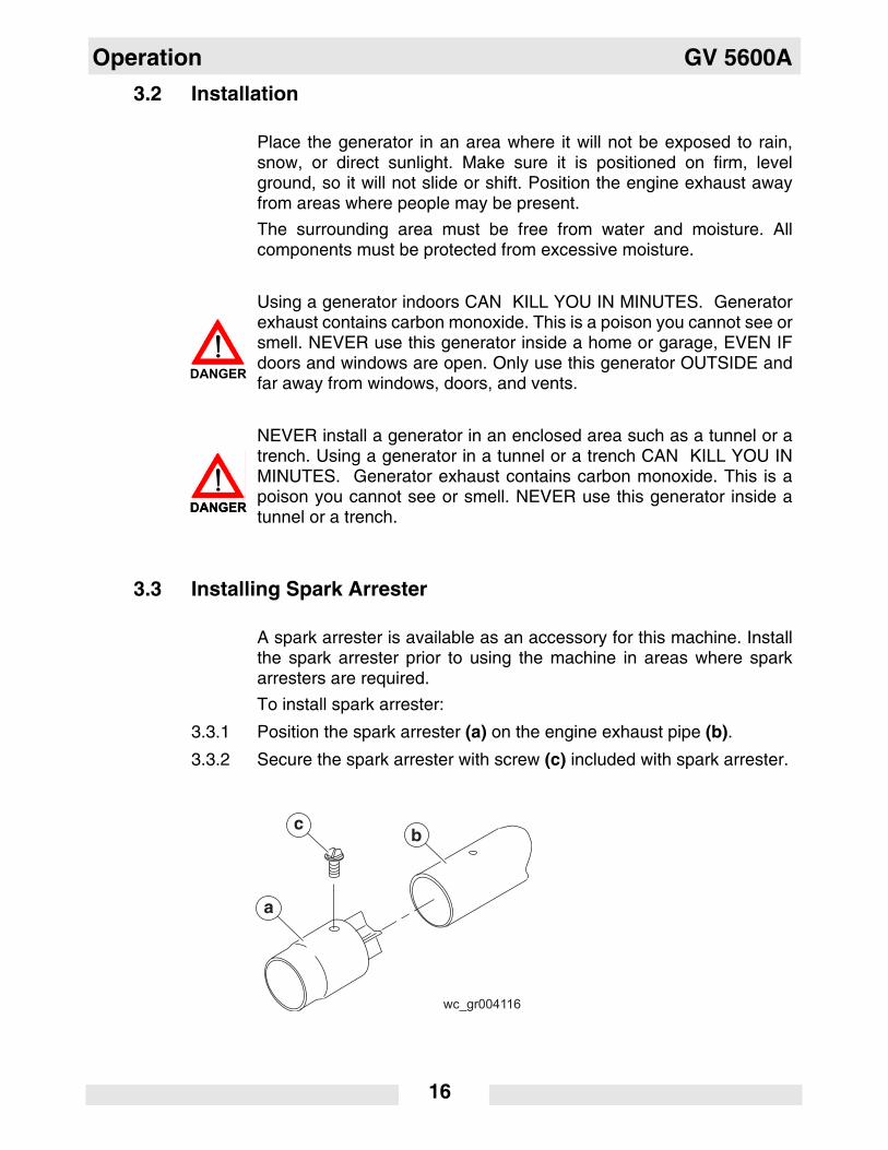
3.3 Installing Spark Arrester
A spark arrester is available as an accessory for this machine. Installthe spark arrester prior to using the machine in areas where sparkarresters are required.
To install spark arrester:
3.3.1 Position the spark arrester (a) on the engine exhaust pipe (b).
3.3.2 Secure the spark arrester with screw (c) included with spark arrester.
DANGER
DANGERDANGER
GV 5600A Operation
17
3.4 Generator Derating
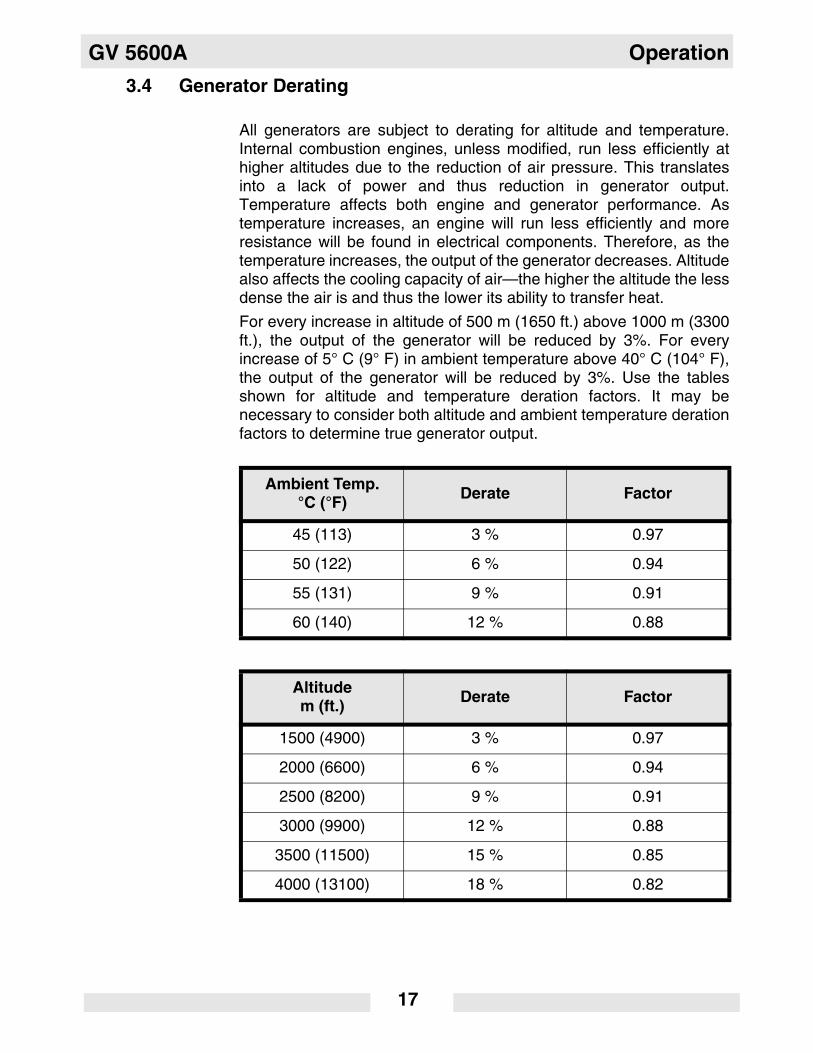
All generators are subject to derating for altitude and temperature.Internal combustion engines, unless modified, run less efficiently athigher altitudes due to the reduction of air pressure. This translatesinto a lack of power and thus reduction in generator output.Temperature affects both engine and generator performance. Astemperature increases, an engine will run less efficiently and moreresistance will be found in electrical components. Therefore, as thetemperature increases, the output of the generator decreases. Altitudealso affects the cooling capacity of air—the higher the altitude the lessdense the air is and thus the lower its ability to transfer heat.
For every increase in altitude of 500 m (1650 ft.) above 1000 m (3300ft.), the output of the generator will be reduced by 3%. For everyincrease of 5° C (9° F) in ambient temperature above 40° C (104° F),the output of the generator will be reduced by 3%. Use the tablesshown for altitude and temperature deration factors. It may benecessary to consider both altitude and ambient temperature derationfactors to determine true generator output.
Ambient Temp.°C (°F) Derate Factor
45 (113) 3 % 0.97
50 (122) 6 % 0.94
55 (131) 9 % 0.91
60 (140) 12 % 0.88
Altitudem (ft.) Derate Factor
1500 (4900) 3 % 0.97
2000 (6600) 6 % 0.94
2500 (8200) 9 % 0.91
3000 (9900) 12 % 0.88
3500 (11500) 15 % 0.85
4000 (13100) 18 % 0.82
Operation GV 5600A
18
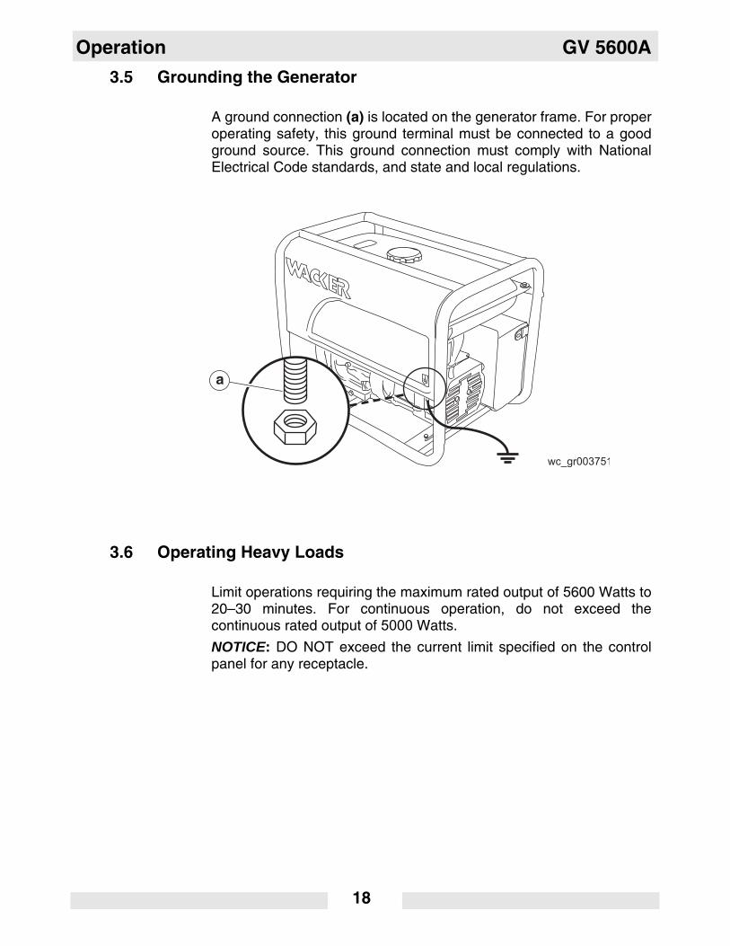
3.5 Grounding the Generator
A ground connection (a) is located on the generator frame. For properoperating safety, this ground terminal must be connected to a goodground source. This ground connection must comply with NationalElectrical Code standards, and state and local regulations.
3.6 Operating Heavy Loads
Limit operations requiring the maximum rated output of 5600 Watts to20–30 minutes. For continuous operation, do not exceed thecontinuous rated output of 5000 Watts.
NOTICE: DO NOT exceed the current limit specified on the controlpanel for any receptacle.
a
GV 5600A Operation
19
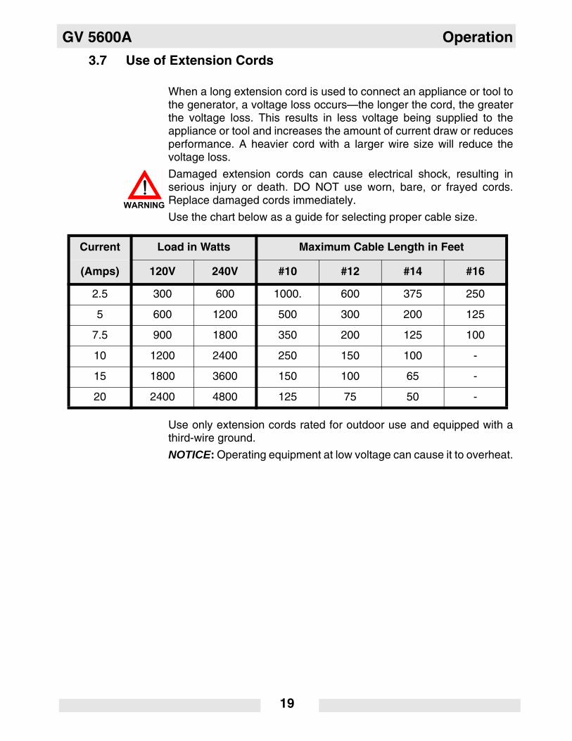
3.7 Use of Extension Cords
When a long extension cord is used to connect an appliance or tool tothe generator, a voltage loss occurs—the longer the cord, the greaterthe voltage loss. This results in less voltage being supplied to theappliance or tool and increases the amount of current draw or reducesperformance. A heavier cord with a larger wire size will reduce thevoltage loss.
Damaged extension cords can cause electrical shock, resulting inserious injury or death. DO NOT use worn, bare, or frayed cords.Replace damaged cords immediately.
Use the chart below as a guide for selecting proper cable size.
Use only extension cords rated for outdoor use and equipped with athird-wire ground.
NOTICE: Operating equipment at low voltage can cause it to overheat.
Current Load in Watts Maximum Cable Length in Feet
(Amps) 120V 240V #10 #12 #14 #16
2.5 300 600 1000. 600 375 250
5 600 1200 500 300 200 125
7.5 900 1800 350 200 125 100
10 1200 2400 250 150 100 -
15 1800 3600 150 100 65 -
20 2400 4800 125 75 50 -
WARNING
Operation GV 5600A
20
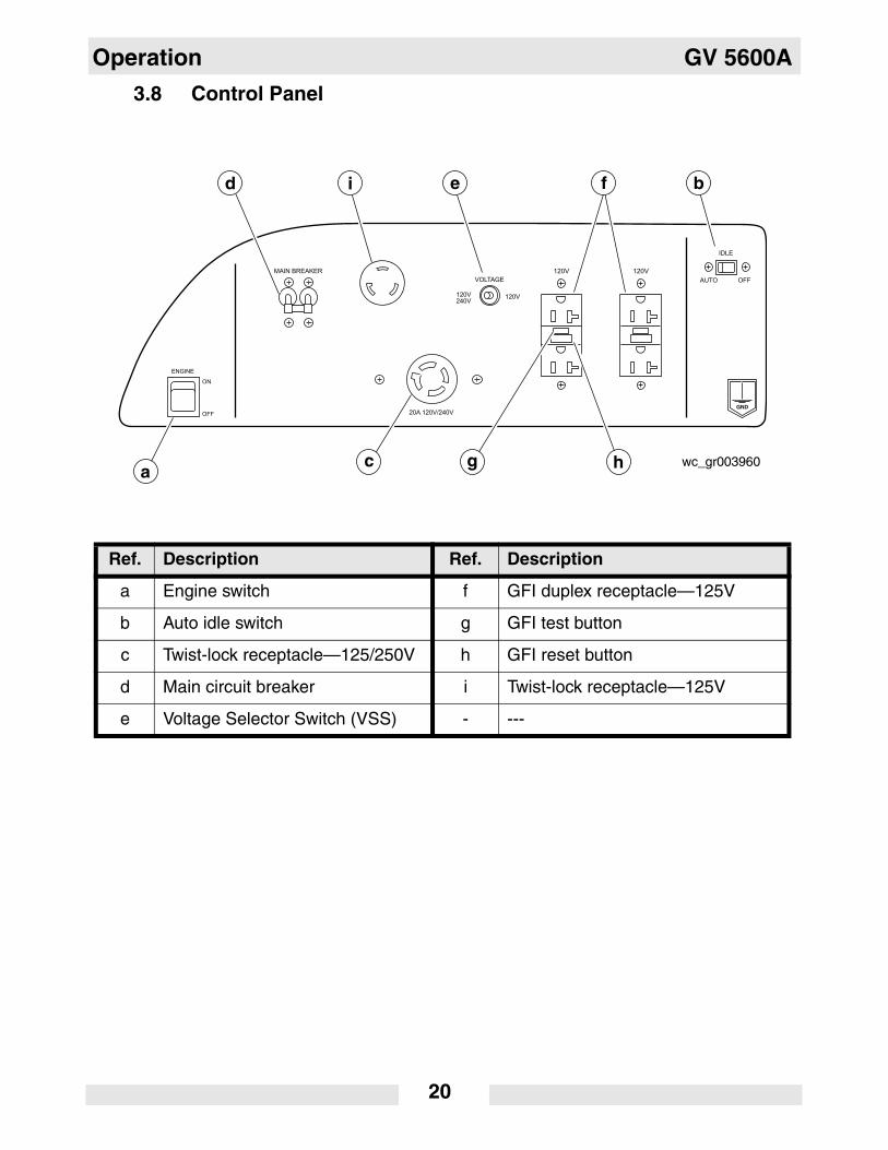
3.8 Control Panel
Ref. Description Ref. Description
a Engine switch f GFI duplex receptacle—125V
b Auto idle switch g GFI test button
c Twist-lock receptacle—125/250V h GFI reset button
d Main circuit breaker i Twist-lock receptacle—125V
e Voltage Selector Switch (VSS) - ---
GV 5600A Operation
21
3.9 Ground Fault Interrupt (GFI)
See Graphic: wc_gr003960
Each of the 125V, 20 Amp receptacles (f) is equipped with a groundfault circuit interrupt (GFI). The GFI shuts off power to the receptaclewhen a ground fault occurs to a piece of equipment attached to thegenerator.
The GFI should be tested for proper operation every time the generatoris used.
To test the GFI:
3.9.1 Disconnect all equipment from the generator.
3.9.2 Start the generator.
3.9.3 Push the TEST button (g) on the receptacle in. Pushing the TESTbutton in shuts off power to the receptacle and causes the RESETbutton (h) to pop out. If the RESET button does not pop out, the GFI isnot working. Do not operate the generator until the problem can becorrected.
3.9.4 Push the RESET button in to restore power to the receptacle.
If the RESET button pops out during operation, stop the generator andcheck the equipment attached to the generator for defects.
3.10 Main Circuit Breaker
See Graphic: wc_gr003960
The generator is protected by a two-pole, 15-Amp per pole, maincircuit breaker (d) located on the control panel.
The main circuit breaker protects the generator from severe overloadsor short circuits. If the main circuit breaker opens, turn the engine offimmediately and determine the cause before restarting. Check theappliances and tools attached to the generator for defects and makesure their power requirements do not exceed the power rating of thegenerator or the current limit of the receptacles.
Operation GV 5600A
22
3.11 Voltage Selection
See Graphic: wc_gr003960
The voltage selector switch (VSS) (e) switches the generator outputbetween the single-voltage mode (120V) and the dual-voltage (120/240V) mode.
In single-voltage mode, the full rated power of the generator is sharedbetween the two 125V GFI duplex receptacles and the 125V twist-lockreceptacle.
In dual-voltage mode, generator power is shared between the 125/250V twist-lock receptacle, the 125V GFI duplex receptacles, and the125V twist-lock receptacle. To achieve full power, use only the 125/250V twist-lock receptacle. Note: Only use the 125/250V twist-lockreceptacle (j) when the VSS is in the 120V/240V position.
NOTICE: NEVER change the position of the VSS when the mainbreaker is in the ON position. This can cause arcing and can damagethe generator. Turn all tools and appliances off and place the maincircuit breaker (d) in the OFF position before changing the position ofthe voltage selector switch.
3.12 Engine Auto Idle
See Graphic: wc_gr003960
The auto idle switch (b) automatically reduces engine speed after allappliances or tools attached to the generator have been turned off.The engine automatically returns to full speed when a tool or applianceis turned back on.
To turn the auto idle feature on, push the auto idle switch to “AUTO”.The AUTO setting is recommended while the generator is running tominimize fuel consumption. To avoid extended engine warm-upperiods, keep switch set to “OFF” when starting the engine and untilthe engine reaches operating temperature.
GV 5600A Operation
23
3.13 Before Starting
3.13.1 Read and understand the safety and operating labels and instructionsat the beginning of this manual
3.13.2 Inspect the generator for any signs of damage which may affectoperation or pose a safety hazard.
3.13.3 Check:
• oil level in engine
• fuel level
• condition of air cleaner
• tightness of external fasteners
• condition of fuel lines.
Note: The engine is equipped with an oil alert system. If the oil level inthe engine drops too low, the engine will not start.
3.13.4 Fill the fuel tank with fresh, regular, unleaded grade gasoline. DO NOTuse an oil/gas mixture. The use of gasohol or any fuel containing morethan 10% ethanol is not recommended. Consult the engine owner'smanual for complete fuel specifications.
Operation GV 5600A
24
3.14 To Start
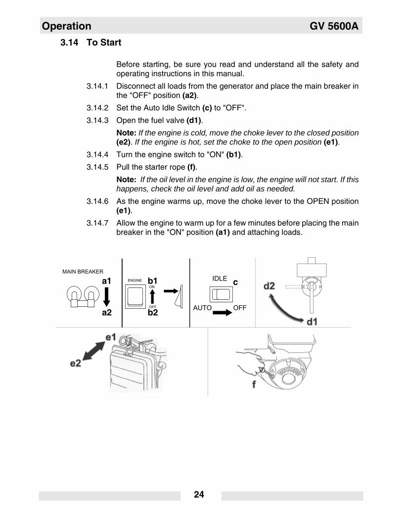
Before starting, be sure you read and understand all the safety andoperating instructions in this manual.
3.14.1 Disconnect all loads from the generator and place the main breaker inthe "OFF" position (a2).
3.14.2 Set the Auto Idle Switch (c) to "OFF".
3.14.3 Open the fuel valve (d1).
Note: If the engine is cold, move the choke lever to the closed position(e2). If the engine is hot, set the choke to the open position (e1).
3.14.4 Turn the engine switch to "ON" (b1).
3.14.5 Pull the starter rope (f).
Note: If the oil level in the engine is low, the engine will not start. If thishappens, check the oil level and add oil as needed.
3.14.6 As the engine warms up, move the choke lever to the OPEN position(e1).
3.14.7 Allow the engine to warm up for a few minutes before placing the mainbreaker in the "ON" position (a1) and attaching loads.
IDLE
OFFAUTO
MAIN BREAKER
a2
a1
b2
b1 c
GV 5600A Operation
25
3.15 To Stop
3.15.1 Turn off and disconnect all tools and appliances attached to thegenerator.
3.15.2 Place main circuit breaker in the "OFF" position (a2).
3.15.3 Turn the engine switch to "OFF" (b2).
3.15.4 Close fuel valve (d2).
Note: To stop the engine quickly in an emergency, turn the engineswitch to "OFF" (b2).
Maintenance GV 5600A
wc_tx000708gb.fm 26
4. Maintenance
4.1 Engine Maintenance
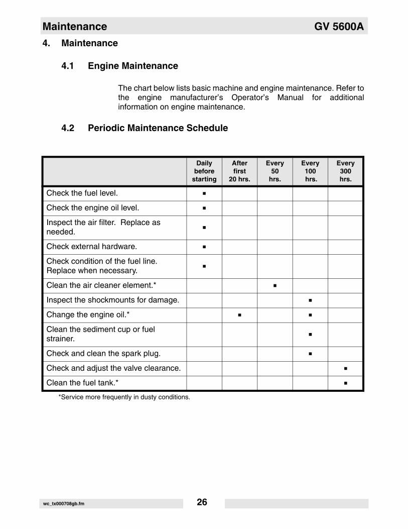
The chart below lists basic machine and engine maintenance. Refer tothe engine manufacturer’s Operator’s Manual for additionalinformation on engine maintenance.
4.2 Periodic Maintenance Schedule
Dailybefore
starting
Afterfirst
20 hrs.
Every50
hrs.
Every100 hrs.
Every300hrs.
Check the fuel level.
Check the engine oil level.
Inspect the air filter. Replace as needed.
Check external hardware.
Check condition of the fuel line. Replace when necessary.
Clean the air cleaner element.*
Inspect the shockmounts for damage.
Change the engine oil.*
Clean the sediment cup or fuel strainer.
Check and clean the spark plug.
Check and adjust the valve clearance.
Clean the fuel tank.*
*Service more frequently in dusty conditions.
GV 5600A Maintenance
wc_tx000708gb.fm 27
4.3 Engine Oil
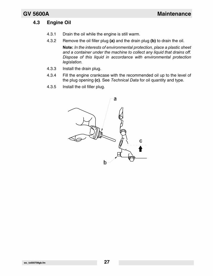
4.3.1 Drain the oil while the engine is still warm.
4.3.2 Remove the oil filler plug (a) and the drain plug (b) to drain the oil.
Note: In the interests of environmental protection, place a plastic sheetand a container under the machine to collect any liquid that drains off.Dispose of this liquid in accordance with environmental protectionlegislation.
4.3.3 Install the drain plug.
4.3.4 Fill the engine crankcase with the recommended oil up to the level ofthe plug opening (c). See Technical Data for oil quantity and type.
4.3.5 Install the oil filler plug.
Maintenance GV 5600A
wc_tx000708gb.fm 28
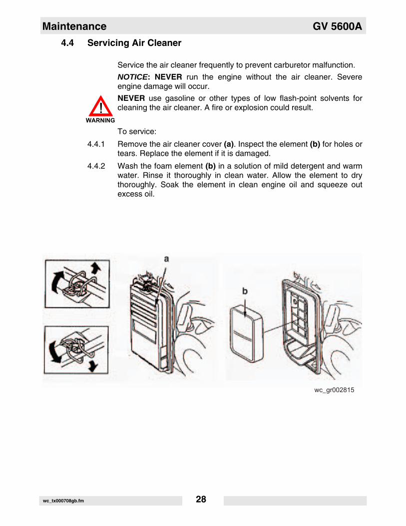
4.4 Servicing Air Cleaner
Service the air cleaner frequently to prevent carburetor malfunction.
NOTICE: NEVER run the engine without the air cleaner. Severeengine damage will occur.
NEVER use gasoline or other types of low flash-point solvents forcleaning the air cleaner. A fire or explosion could result.
To service:
4.4.1 Remove the air cleaner cover (a). Inspect the element (b) for holes ortears. Replace the element if it is damaged.
4.4.2 Wash the foam element (b) in a solution of mild detergent and warmwater. Rinse it thoroughly in clean water. Allow the element to drythoroughly. Soak the element in clean engine oil and squeeze outexcess oil.
WARNING
wc_gr002815
GV 5600A Maintenance
wc_tx000708gb.fm 29
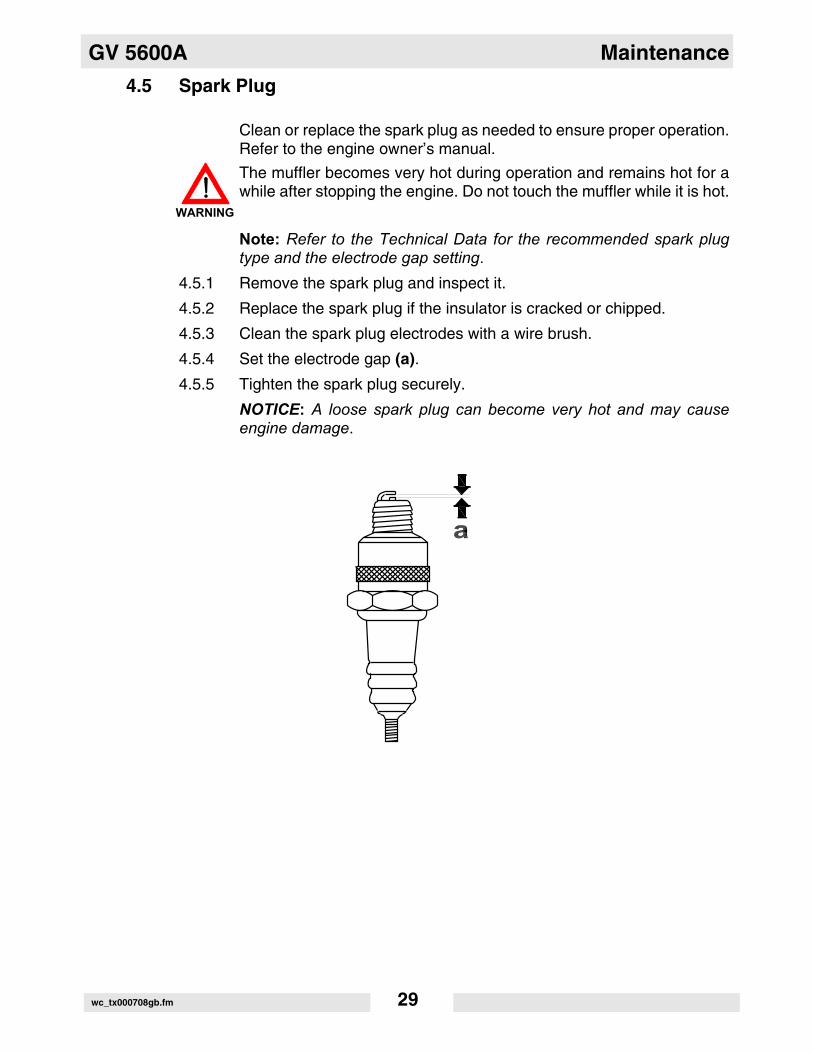
4.5 Spark Plug
Clean or replace the spark plug as needed to ensure proper operation.Refer to the engine owner’s manual.
The muffler becomes very hot during operation and remains hot for awhile after stopping the engine. Do not touch the muffler while it is hot.
Note: Refer to the Technical Data for the recommended spark plugtype and the electrode gap setting.
4.5.1 Remove the spark plug and inspect it.
4.5.2 Replace the spark plug if the insulator is cracked or chipped.
4.5.3 Clean the spark plug electrodes with a wire brush.
4.5.4 Set the electrode gap (a).
4.5.5 Tighten the spark plug securely.
NOTICE: A loose spark plug can become very hot and may causeengine damage.
WARNING
Maintenance GV 5600A
wc_tx000708gb.fm 30
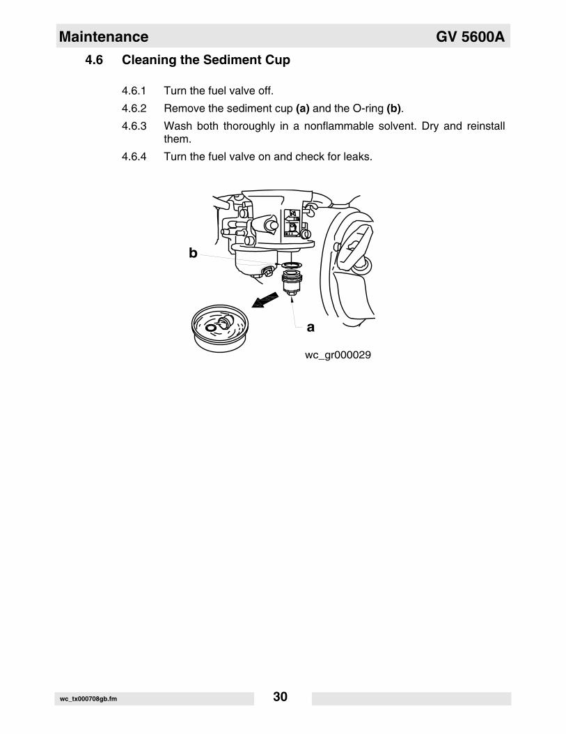
4.6 Cleaning the Sediment Cup
4.6.1 Turn the fuel valve off.
4.6.2 Remove the sediment cup (a) and the O-ring (b).
4.6.3 Wash both thoroughly in a nonflammable solvent. Dry and reinstallthem.
4.6.4 Turn the fuel valve on and check for leaks.
wc_gr000029
b
a
GV 5600A Maintenance
wc_tx000708gb.fm 31
4.7 Storage
Before storing the generator for a long period of time:
4.7.1 Close the fuel valve and remove and empty the sediment cup or fuelstrainer.
4.7.2 Disconnect the fuel line from the carburetor. Place open end of fuel lineinto a suitable container and open fuel valve to drain fuel from tank.
Gasoline is extremely flammable. Drain the fuel tank in a well-ventilated area. DO NOT drain the fuel tank in an area with flames orsparks.
4.7.3 Loosen the drain screw on the carburetor and drain any remaining fuelfrom the carburetor.
4.7.4 Change the engine oil.
4.7.5 Remove the spark plug and pour approximately 30 ml (1 ounce) ofclean engine oil into the cylinder. Crank the engine a few turns todistribute the oil to the inside of the cylinder walls.
4.7.6 Pull the starter rope slowly until resistance is felt and leave the handlein this position. This ensures that the intake and exhaust valves areclosed.
4.7.7 Store the generator in a clean, dry area.
WARNING
Maintenance GV 5600A
wc_tx000708gb.fm 32
4.8 Transport
Let the engine cool before transporting the generator or storingindoors, to avoid burns or fire hazards.
When transporting the generator:
4.8.1 Turn the engine fuel valve to the OFF position.
4.8.2 Position the generator level to prevent fuel from spilling.
4.8.3 Secure the generator by tying it down with a suitable rope.
When transporting the machine by hand, be sure to employ manpowercommensurate with the weight of the machine. To avoid back injurywhen lifting the machine, bend the knees to pick it up rather thanbending your back only.
WARNING
WARNING
GV 5600A Maintenance
wc_tx000708gb.fm 33
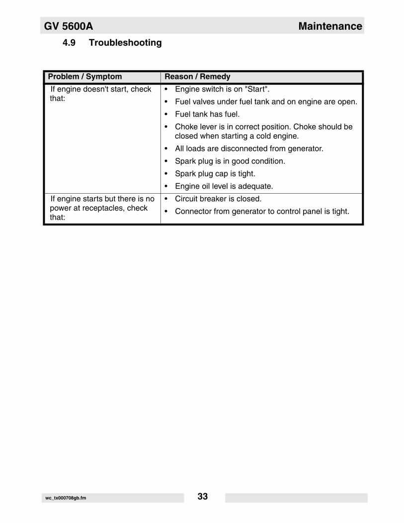
4.9 Troubleshooting
Problem / Symptom Reason / Remedy
If engine doesn't start, check that:
• Engine switch is on "Start".
• Fuel valves under fuel tank and on engine are open.
• Fuel tank has fuel.
• Choke lever is in correct position. Choke should be closed when starting a cold engine.
• All loads are disconnected from generator.
• Spark plug is in good condition.
• Spark plug cap is tight.
• Engine oil level is adequate.
If engine starts but there is no power at receptacles, check that:
• Circuit breaker is closed.
• Connector from generator to control panel is tight.
Technical Data GV 5600A
34
5. Technical Data
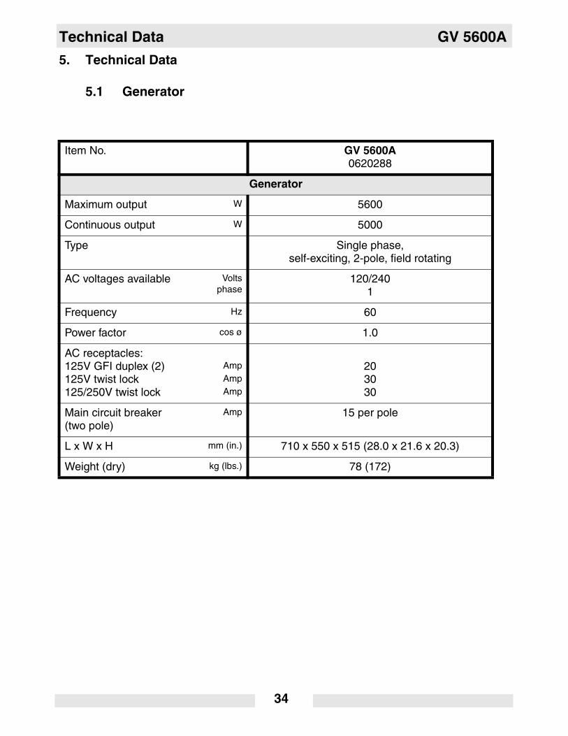
5.1 Generator
Item No. GV 5600A0620288
Generator
Maximum output W 5600
Continuous output W 5000
Type Single phase,self-exciting, 2-pole, field rotating
AC voltages available Voltsphase
120/2401
Frequency Hz 60
Power factor cos ø 1.0
AC receptacles:125V GFI duplex (2)125V twist lock125/250V twist lock
AmpAmpAmp
203030
Main circuit breaker(two pole)
Amp 15 per pole
L x W x H mm (in.) 710 x 550 x 515 (28.0 x 21.6 x 20.3)
Weight (dry) kg (lbs.) 78 (172)
GV 5600A Technical Data
35
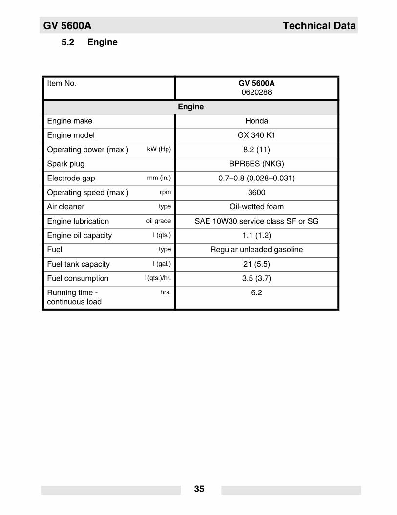
5.2 Engine
Item No. GV 5600A0620288
Engine
Engine make Honda
Engine model GX 340 K1
Operating power (max.) kW (Hp) 8.2 (11)
Spark plug BPR6ES (NKG)
Electrode gap mm (in.) 0.7–0.8 (0.028–0.031)
Operating speed (max.) rpm 3600
Air cleaner type Oil-wetted foam
Engine lubrication oil grade SAE 10W30 service class SF or SG
Engine oil capacity l (qts.) 1.1 (1.2)
Fuel type Regular unleaded gasoline
Fuel tank capacity l (gal.) 21 (5.5)
Fuel consumption l (qts.)/hr. 3.5 (3.7)
Running time - continuous load
hrs. 6.2
Technical Data GV 5600A
36
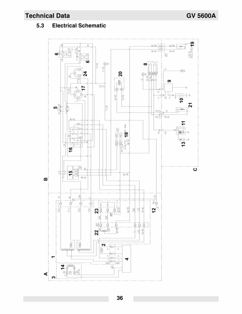
5.3 Electrical Schematic
AB
15
16
17
24
18
6
65
3
14
1
9
8
19
20
10
11
21
13
12
4
2
22
23
C
GV 5600A Technical Data
37
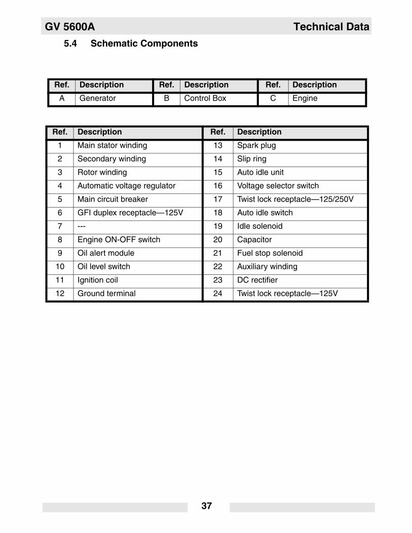
5.4 Schematic Components
Ref. Description Ref. Description Ref. Description
A Generator B Control Box C Engine
Ref. Description Ref. Description
1 Main stator winding 13 Spark plug
2 Secondary winding 14 Slip ring
3 Rotor winding 15 Auto idle unit
4 Automatic voltage regulator 16 Voltage selector switch
5 Main circuit breaker 17 Twist lock receptacle—125/250V
6 GFI duplex receptacle—125V 18 Auto idle switch
7 --- 19 Idle solenoid
8 Engine ON-OFF switch 20 Capacitor
9 Oil alert module 21 Fuel stop solenoid
10 Oil level switch 22 Auxiliary winding
11 Ignition coil 23 DC rectifier
12 Ground terminal 24 Twist lock receptacle—125V

Wacker Construction Equipment AG · Preußenstraße 41 · D-80809 München · Tel.: +49-(0)89-3 54 02 - 0 · Fax: +49 - (0)89-3 54 02-3 90Wacker Corporation · P.O. Box 9007 · Menomonee Falls, WI 53052-9007 · Tel. : (262) 255-0500 · Fax: (262) 255-0550 · Tel. : (800) 770-0957Wacker Asia Pacific Operations · Skyline Tower, Suite 2303, 23/F · 39 Wang Kwong Road, Kowloon Bay, Hong Kong · Tel. +852 2406 60 32 · Fax: +852 2406 60 21