Embed Size (px)
Citation preview
Rockwell Automation Library of Process Objects: Common Mode Block (P_Mode)Version 3.5
Reference Manual
IMPORTANT This manual applies to the Rockwell Automation Library of Process Objects version 3.5 or earlier.For Rockwell Automation Library of Process Objects version 4.0 or later, use the following manuals:• PROCES-RM013 contains logic instructions• PROCES-RM014 contains display elements
Important User Information
Read this document and the documents listed in the additional resources section about installation, configuration, and operation of this equipment before you install, configure, operate, or maintain this product. Users are required to familiarize themselves with installation and wiring instructions in addition to requirements of all applicable codes, laws, and standards.
Activities including installation, adjustments, putting into service, use, assembly, disassembly, and maintenance are required to be carried out by suitably trained personnel in accordance with applicable code of practice.
If this equipment is used in a manner not specified by the manufacturer, the protection provided by the equipment may be impaired.
In no event will Rockwell Automation, Inc. be responsible or liable for indirect or consequential damages resulting from the use or application of this equipment.
The examples and diagrams in this manual are included solely for illustrative purposes. Because of the many variables and requirements associated with any particular installation, Rockwell Automation, Inc. cannot assume responsibility or liability for actual use based on the examples and diagrams.
No patent liability is assumed by Rockwell Automation, Inc. with respect to use of information, circuits, equipment, or software described in this manual.
Reproduction of the contents of this manual, in whole or in part, without written permission of Rockwell Automation, Inc., is prohibited.
Throughout this manual, when necessary, we use notes to make you aware of safety considerations.
Labels may also be on or inside the equipment to provide specific precautions.
Allen-Bradley, Rockwell Software, Rockwell Automation, RSLogix, Logix5000, FactoryTalk, PlantPAx, and ControlLogix are trademarks of Rockwell Automation, Inc.
Trademarks not belonging to Rockwell Automation are property of their respective companies.
WARNING: Identifies information about practices or circumstances that can cause an explosion in a hazardous environment, which may lead to personal injury or death, property damage, or economic loss.
ATTENTION: Identifies information about practices or circumstances that can lead to personal injury or death, property damage, or economic loss. Attentions help you identify a hazard, avoid a hazard, and recognize the consequence.
IMPORTANT Identifies information that is critical for successful application and understanding of the product.
SHOCK HAZARD: Labels may be on or inside the equipment, for example, a drive or motor, to alert people that dangerous voltage may be present.
BURN HAZARD: Labels may be on or inside the equipment, for example, a drive or motor, to alert people that surfaces may reach dangerous temperatures.
ARC FLASH HAZARD: Labels may be on or inside the equipment, for example, a motor control center, to alert people to potential Arc Flash. Arc Flash will cause severe injury or death. Wear proper Personal Protective Equipment (PPE). Follow ALL Regulatory requirements for safe work practices and for Personal Protective Equipment (PPE).
Table of Contents
Preface Software Compatibility and Content Revision. . . . . . . . . . . . . . . . . . . . . . . 5Additional Resources . . . . . . . . . . . . . . . . . . . . . . . . . . . . . . . . . . . . . . . . . . . . . . 5
Common Mode Block (P_Mode) Guidelines . . . . . . . . . . . . . . . . . . . . . . . . . . . . . . . . . . . . . . . . . . . . . . . . . . . . . . . . 7Functional Description . . . . . . . . . . . . . . . . . . . . . . . . . . . . . . . . . . . . . . . . . . . . 8Required Files. . . . . . . . . . . . . . . . . . . . . . . . . . . . . . . . . . . . . . . . . . . . . . . . . . . . . 9
Controller File . . . . . . . . . . . . . . . . . . . . . . . . . . . . . . . . . . . . . . . . . . . . . . . . 9Visualization Files . . . . . . . . . . . . . . . . . . . . . . . . . . . . . . . . . . . . . . . . . . . . . 9
Controller Code . . . . . . . . . . . . . . . . . . . . . . . . . . . . . . . . . . . . . . . . . . . . . . . . . 10Common Mode Block Input Structure . . . . . . . . . . . . . . . . . . . . . . . . . 10Common Mode Block Output Structure . . . . . . . . . . . . . . . . . . . . . . . 11
Operations . . . . . . . . . . . . . . . . . . . . . . . . . . . . . . . . . . . . . . . . . . . . . . . . . . . . . . 12Modes . . . . . . . . . . . . . . . . . . . . . . . . . . . . . . . . . . . . . . . . . . . . . . . . . . . . . . . 13Associated Tags . . . . . . . . . . . . . . . . . . . . . . . . . . . . . . . . . . . . . . . . . . . . . . 14Alarms. . . . . . . . . . . . . . . . . . . . . . . . . . . . . . . . . . . . . . . . . . . . . . . . . . . . . . . 16Simulation . . . . . . . . . . . . . . . . . . . . . . . . . . . . . . . . . . . . . . . . . . . . . . . . . . . 16Execution . . . . . . . . . . . . . . . . . . . . . . . . . . . . . . . . . . . . . . . . . . . . . . . . . . . . 17
Display Elements . . . . . . . . . . . . . . . . . . . . . . . . . . . . . . . . . . . . . . . . . . . . . . . . . 18Mode Indicator . . . . . . . . . . . . . . . . . . . . . . . . . . . . . . . . . . . . . . . . . . . . . . 18Mode Totem Pole . . . . . . . . . . . . . . . . . . . . . . . . . . . . . . . . . . . . . . . . . . . . 19Operator Buttons. . . . . . . . . . . . . . . . . . . . . . . . . . . . . . . . . . . . . . . . . . . . . 19Maintenance Buttons . . . . . . . . . . . . . . . . . . . . . . . . . . . . . . . . . . . . . . . . . 20Engineering Buttons . . . . . . . . . . . . . . . . . . . . . . . . . . . . . . . . . . . . . . . . . . 20Mode Faceplate Help . . . . . . . . . . . . . . . . . . . . . . . . . . . . . . . . . . . . . . . . . 21
Rockwell Automation Publication SYSLIB-RM005E-EN-E - January 2016 3
Table of Contents
Notes:
4 Rockwell Automation Publication SYSLIB-RM005E-EN-E - January 2016
Preface
This manual contains new and updated information. Changes throughout this revision are marked by change bars, as shown to the right of this paragraph.
Software Compatibility and Content Revision
For the latest compatible software information and to download the Rockwell Automation® Library of Process Objects, see the Product Compatibility and Download Center at http://www.rockwellautomation.com/rockwellautomation/support/pcdc.page.
For general library considerations, see Rockwell Automation Library of Process Objects, publication PROCES-RM002.
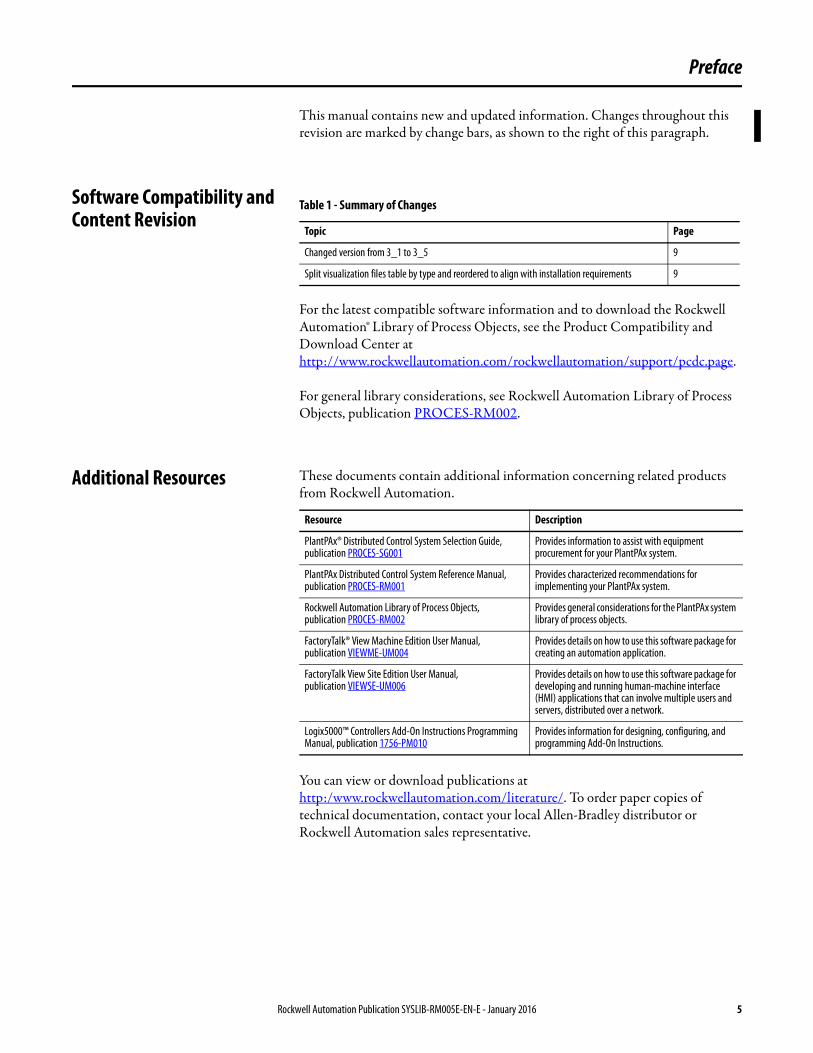
Additional Resources These documents contain additional information concerning related products from Rockwell Automation.
You can view or download publications athttp:/www.rockwellautomation.com/literature/. To order paper copies of technical documentation, contact your local Allen-Bradley distributor or Rockwell Automation sales representative.
Table 1 - Summary of Changes
Topic Page
Changed version from 3_1 to 3_5 9
Split visualization files table by type and reordered to align with installation requirements 9
Resource Description
PlantPAx® Distributed Control System Selection Guide, publication PROCES-SG001
Provides information to assist with equipment procurement for your PlantPAx system.
PlantPAx Distributed Control System Reference Manual, publication PROCES-RM001
Provides characterized recommendations for implementing your PlantPAx system.
Rockwell Automation Library of Process Objects,publication PROCES-RM002
Provides general considerations for the PlantPAx system library of process objects.
FactoryTalk® View Machine Edition User Manual,publication VIEWME-UM004
Provides details on how to use this software package for creating an automation application.
FactoryTalk View Site Edition User Manual,publication VIEWSE-UM006
Provides details on how to use this software package for developing and running human-machine interface (HMI) applications that can involve multiple users and servers, distributed over a network.
Logix5000™ Controllers Add-On Instructions Programming Manual, publication 1756-PM010
Provides information for designing, configuring, and programming Add-On Instructions.
Rockwell Automation Publication SYSLIB-RM005E-EN-E - January 2016 5

Preface
Notes:
6 Rockwell Automation Publication SYSLIB-RM005E-EN-E - January 2016
Common Mode Block (P_Mode)
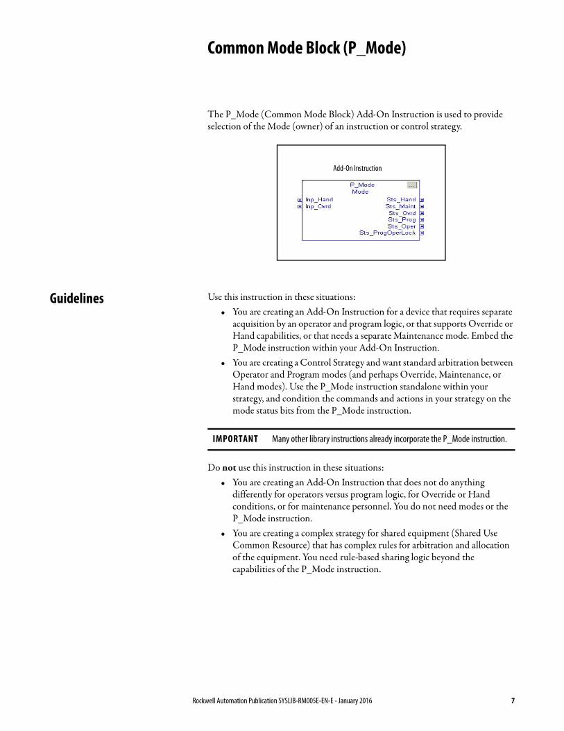
The P_Mode (Common Mode Block) Add-On Instruction is used to provide selection of the Mode (owner) of an instruction or control strategy.
Guidelines Use this instruction in these situations:• You are creating an Add-On Instruction for a device that requires separate
acquisition by an operator and program logic, or that supports Override or Hand capabilities, or that needs a separate Maintenance mode. Embed the P_Mode instruction within your Add-On Instruction.
• You are creating a Control Strategy and want standard arbitration between Operator and Program modes (and perhaps Override, Maintenance, or Hand modes). Use the P_Mode instruction standalone within your strategy, and condition the commands and actions in your strategy on the mode status bits from the P_Mode instruction.
Do not use this instruction in these situations:• You are creating an Add-On Instruction that does not do anything
differently for operators versus program logic, for Override or Hand conditions, or for maintenance personnel. You do not need modes or the P_Mode instruction.
• You are creating a complex strategy for shared equipment (Shared Use Common Resource) that has complex rules for arbitration and allocation of the equipment. You need rule-based sharing logic beyond the capabilities of the P_Mode instruction.
Add-On Instruction
IMPORTANT Many other library instructions already incorporate the P_Mode instruction.
Rockwell Automation Publication SYSLIB-RM005E-EN-E - January 2016 7
Common Mode Block (P_Mode)
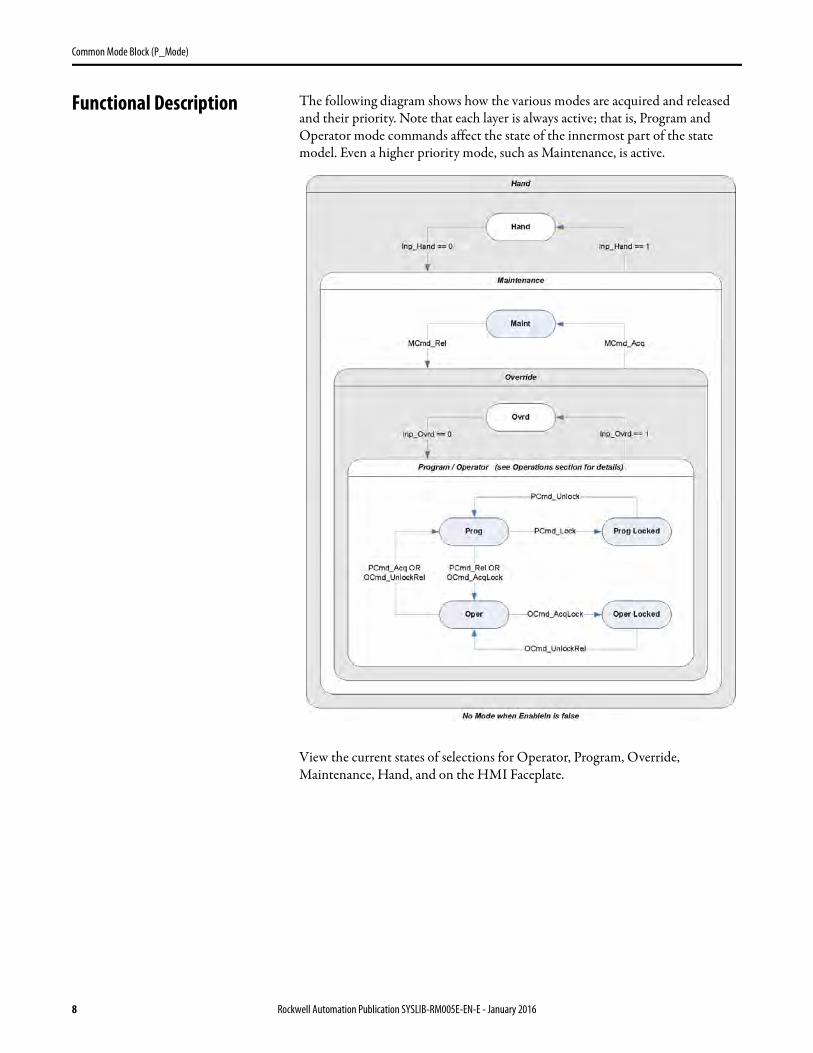
Functional Description The following diagram shows how the various modes are acquired and released and their priority. Note that each layer is always active; that is, Program and Operator mode commands affect the state of the innermost part of the state model. Even a higher priority mode, such as Maintenance, is active.
View the current states of selections for Operator, Program, Override, Maintenance, Hand, and on the HMI Faceplate.
8 Rockwell Automation Publication SYSLIB-RM005E-EN-E - January 2016
Common Mode Block (P_Mode)
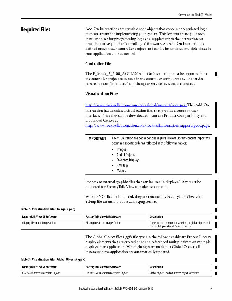
Required Files Add-On Instructions are reusable code objects that contain encapsulated logic that can streamline implementing your system. This lets you create your own instruction set for programming logic as a supplement to the instruction set provided natively in the ControlLogix® firmware. An Add-On Instruction is defined once in each controller project, and can be instantiated multiple times in your application code as needed.
Controller File
The P_Mode_3_5-00_AOI.L5X Add-On Instruction must be imported into the controller project to be used in the controller configuration. The service release number (boldfaced) can change as service revisions are created.
Visualization Files
http://www.rockwellautomation.com/global/support/pcdc.pageThis Add-On Instruction has associated visualization files that provide a common user interface. These files can be downloaded from the Product Compatibility and Download Center at http://www.rockwellautomation.com/rockwellautomation/support/pcdc.page.
Images are external graphic files that can be used in displays. They must be imported for FactoryTalk View to make use of them.
When PNG files are imported, they are renamed by FactoryTalk View with a .bmp file extension, but retain a .png format.
The Global Object files (.ggfx file type) in the following table are Process Library display elements that are created once and referenced multiple times on multiple displays in an application. When changes are made to a Global Object, all instances in the application are automatically updated.
IMPORTANT The visualization file dependencies require Process Library content imports to occur in a specific order as reflected in the following tables:• Images• Global Objects• Standard Displays• HMI Tags• Macros
Table 2 - Visualization Files: Images (.png)
FactoryTalk View SE Software FactoryTalk View ME Software Description
All .png files in the images folder All .png files in the images folder These are the common icons used in the global objects and standard displays for all Process Objects.
Table 3 - Visualization Files: Global Objects (.ggfx)
FactoryTalk View SE Software FactoryTalk View ME Software Description
(RA-BAS) Common Faceplate Objects (RA-BAS-ME) Common Faceplate Objects Global objects used on process object faceplates.
Rockwell Automation Publication SYSLIB-RM005E-EN-E - January 2016 9
Common Mode Block (P_Mode)
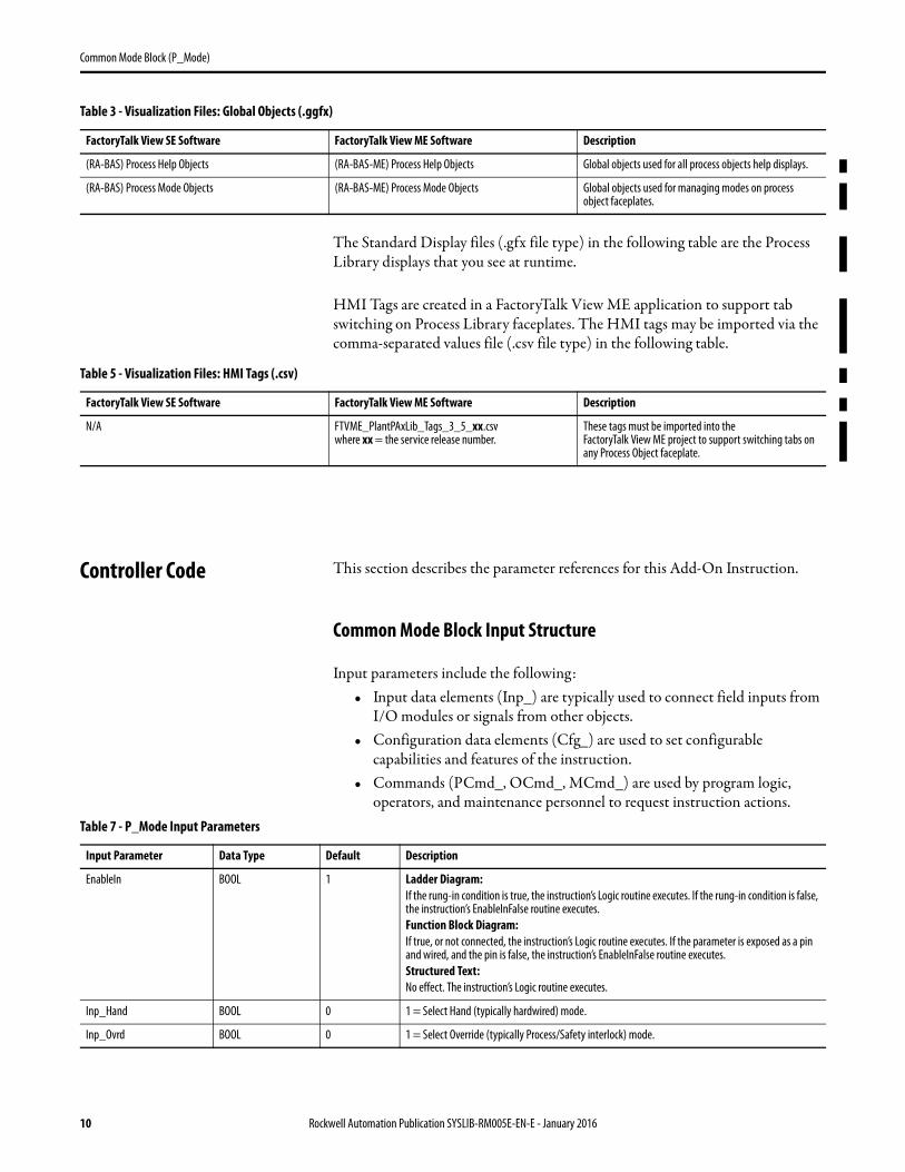
The Standard Display files (.gfx file type) in the following table are the Process Library displays that you see at runtime.
HMI Tags are created in a FactoryTalk View ME application to support tab switching on Process Library faceplates. The HMI tags may be imported via the comma-separated values file (.csv file type) in the following table.
Controller Code This section describes the parameter references for this Add-On Instruction.
Common Mode Block Input Structure
Input parameters include the following:• Input data elements (Inp_) are typically used to connect field inputs from
I/O modules or signals from other objects.• Configuration data elements (Cfg_) are used to set configurable
capabilities and features of the instruction.• Commands (PCmd_, OCmd_, MCmd_) are used by program logic,
operators, and maintenance personnel to request instruction actions.
(RA-BAS) Process Help Objects (RA-BAS-ME) Process Help Objects Global objects used for all process objects help displays.
(RA-BAS) Process Mode Objects (RA-BAS-ME) Process Mode Objects Global objects used for managing modes on process object faceplates.
Table 3 - Visualization Files: Global Objects (.ggfx)
FactoryTalk View SE Software FactoryTalk View ME Software Description
Table 5 - Visualization Files: HMI Tags (.csv)
FactoryTalk View SE Software FactoryTalk View ME Software Description
N/A FTVME_PlantPAxLib_Tags_3_5_xx.csvwhere xx = the service release number.
These tags must be imported into theFactoryTalk View ME project to support switching tabs on any Process Object faceplate.
Table 7 - P_Mode Input Parameters
Input Parameter Data Type Default Description
EnableIn BOOL 1 Ladder Diagram:If the rung-in condition is true, the instruction’s Logic routine executes. If the rung-in condition is false, the instruction’s EnableInFalse routine executes.Function Block Diagram:If true, or not connected, the instruction’s Logic routine executes. If the parameter is exposed as a pin and wired, and the pin is false, the instruction’s EnableInFalse routine executes.Structured Text:No effect. The instruction’s Logic routine executes.
Inp_Hand BOOL 0 1 = Select Hand (typically hardwired) mode.
Inp_Ovrd BOOL 0 1 = Select Override (typically Process/Safety interlock) mode.
10 Rockwell Automation Publication SYSLIB-RM005E-EN-E - January 2016
Common Mode Block (P_Mode)
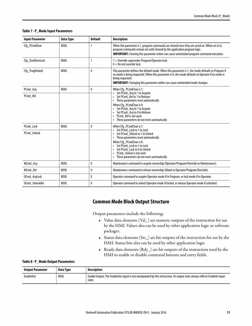
Common Mode Block Output Structure
Output parameters include the following:• Value data elements (Val_) are numeric outputs of the instruction for use
by the HMI. Values also can be used by other application logic or software packages.
• Status data elements (Sts_) are bit outputs of the instruction for use by the HMI. Status bits also can be used by other application logic.
• Ready data elements (Rdy_) are bit outputs of the instruction used by the HMI to enable or disable command buttons and entry fields.
Cfg_PCmdClear BOOL 1 When this parameter is 1, program commands are cleared once they are acted on. When set to 0, program commands remain set until cleared by the application program logic.IMPORTANT: Clearing this parameter online can cause unintended program command execution.
Cfg_OvrdOverLock BOOL 1 1 = Override supersedes Program/Operator lock.0 = Do not override lock.
Cfg_ProgDefault BOOL 0 This parameter defines the default mode. When this parameter is 1, the mode defaults to Program if no mode is being requested. When this parameter is 0, the mode defaults to Operator if no mode is being requested. IMPORTANT: Changing this parameter online can cause unintended mode changes.
PCmd_Acq BOOL 0 When Cfg_PCmdClear is 1:• Set PCmd_Acq to 1 to Acquire• Set PCmd_Rel to 1 to Release• These parameters reset automaticallyWhen Cfg_PCmdClear is 0:• Set PCmd_Acq to 1 to Acquire• Set PCmd_Acq to 0 to Release• PCmd_Rel is not used• These parameters do not reset automatically
PCmd_Rel
PCmd_Lock BOOL 0 When Cfg_PCmdClear is 1:• Set PCmd_Lock to 1 to Lock• Set PCmd_Unlock to 1 to Unlock• These parameters reset automaticallyWhen Cfg_PCmdClear is 0:• Set PCmd_Lock to 1 to Lock• Set PCmd_Lock to 0 to Unlock• PCmd_Unlock is not used• These parameters do not reset automatically
PCmd_Unlock
MCmd_Acq BOOL 0 Maintenance command to acquire ownership (Operator/Program/Override to Maintenance).
MCmd_Rel BOOL 0 Maintenance command to release ownership (Maint to Operator/Program/Override).
OCmd_AcqLock BOOL 0 Operator command to acquire Operator mode if in Program, or lock mode if in Operator.
OCmd_UnlockRel BOOL 0 Operator command to unlock Operator mode if locked, or release Operator mode if unlocked.
Table 7 - P_Mode Input Parameters
Input Parameter Data Type Default Description
Table 8 - P_Mode Output Parameters
Output Parameter Data Type Description
EnableOut BOOL Enable Output: The EnableOut signal is not manipulated by this instruction. Its output state always reflects EnableIn input state.
Rockwell Automation Publication SYSLIB-RM005E-EN-E - January 2016 11
Common Mode Block (P_Mode)
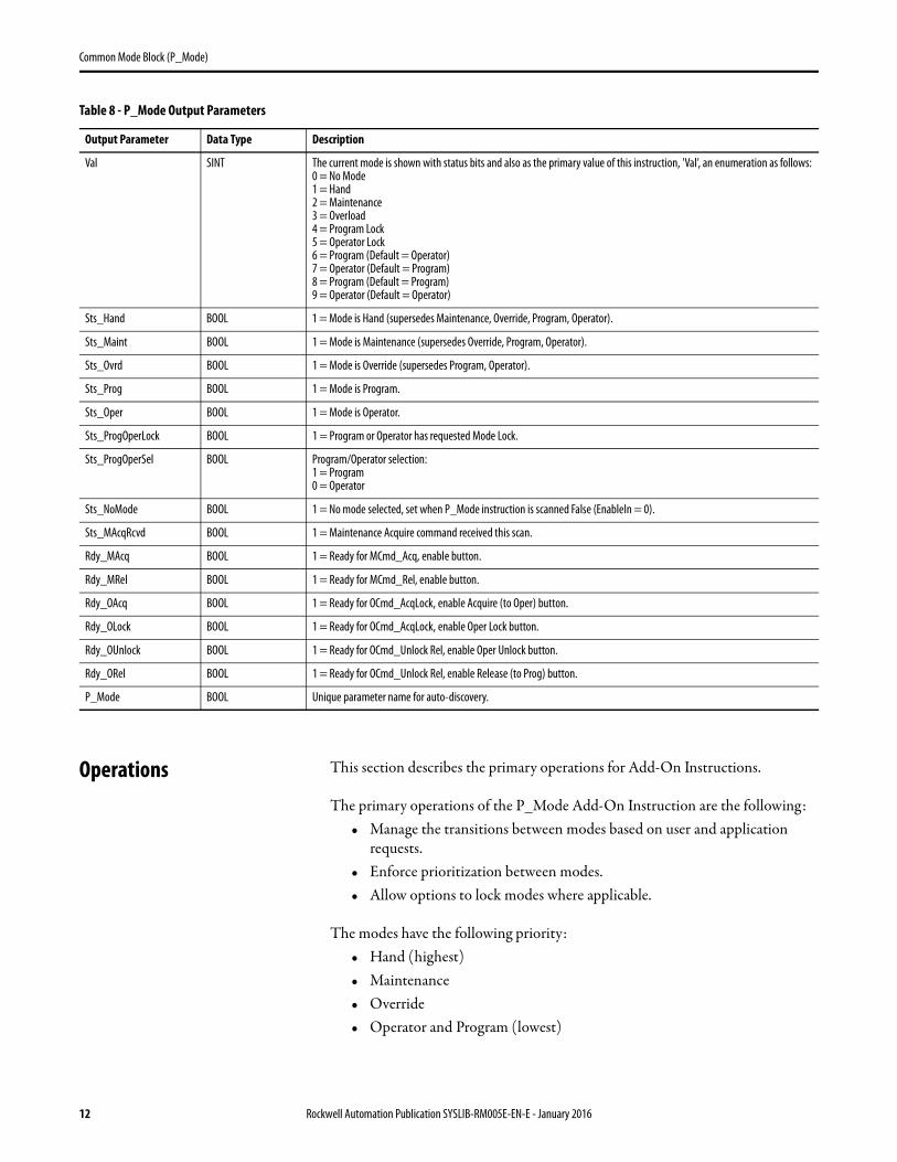
Operations This section describes the primary operations for Add-On Instructions.
The primary operations of the P_Mode Add-On Instruction are the following:• Manage the transitions between modes based on user and application
requests.• Enforce prioritization between modes.• Allow options to lock modes where applicable.
The modes have the following priority:• Hand (highest)• Maintenance• Override• Operator and Program (lowest)
Val SINT The current mode is shown with status bits and also as the primary value of this instruction, 'Val', an enumeration as follows:0 = No Mode1 = Hand2 = Maintenance3 = Overload4 = Program Lock5 = Operator Lock6 = Program (Default = Operator)7 = Operator (Default = Program)8 = Program (Default = Program)9 = Operator (Default = Operator)
Sts_Hand BOOL 1 = Mode is Hand (supersedes Maintenance, Override, Program, Operator).
Sts_Maint BOOL 1 = Mode is Maintenance (supersedes Override, Program, Operator).
Sts_Ovrd BOOL 1 = Mode is Override (supersedes Program, Operator).
Sts_Prog BOOL 1 = Mode is Program.
Sts_Oper BOOL 1 = Mode is Operator.
Sts_ProgOperLock BOOL 1 = Program or Operator has requested Mode Lock.
Sts_ProgOperSel BOOL Program/Operator selection:1 = Program0 = Operator
Sts_NoMode BOOL 1 = No mode selected, set when P_Mode instruction is scanned False (EnableIn = 0).
Sts_MAcqRcvd BOOL 1 = Maintenance Acquire command received this scan.
Rdy_MAcq BOOL 1 = Ready for MCmd_Acq, enable button.
Rdy_MRel BOOL 1 = Ready for MCmd_Rel, enable button.
Rdy_OAcq BOOL 1 = Ready for OCmd_AcqLock, enable Acquire (to Oper) button.
Rdy_OLock BOOL 1 = Ready for OCmd_AcqLock, enable Oper Lock button.
Rdy_OUnlock BOOL 1 = Ready for OCmd_Unlock Rel, enable Oper Unlock button.
Rdy_ORel BOOL 1 = Ready for OCmd_Unlock Rel, enable Release (to Prog) button.
P_Mode BOOL Unique parameter name for auto-discovery.
Table 8 - P_Mode Output Parameters
Output Parameter Data Type Description
12 Rockwell Automation Publication SYSLIB-RM005E-EN-E - January 2016
Common Mode Block (P_Mode)
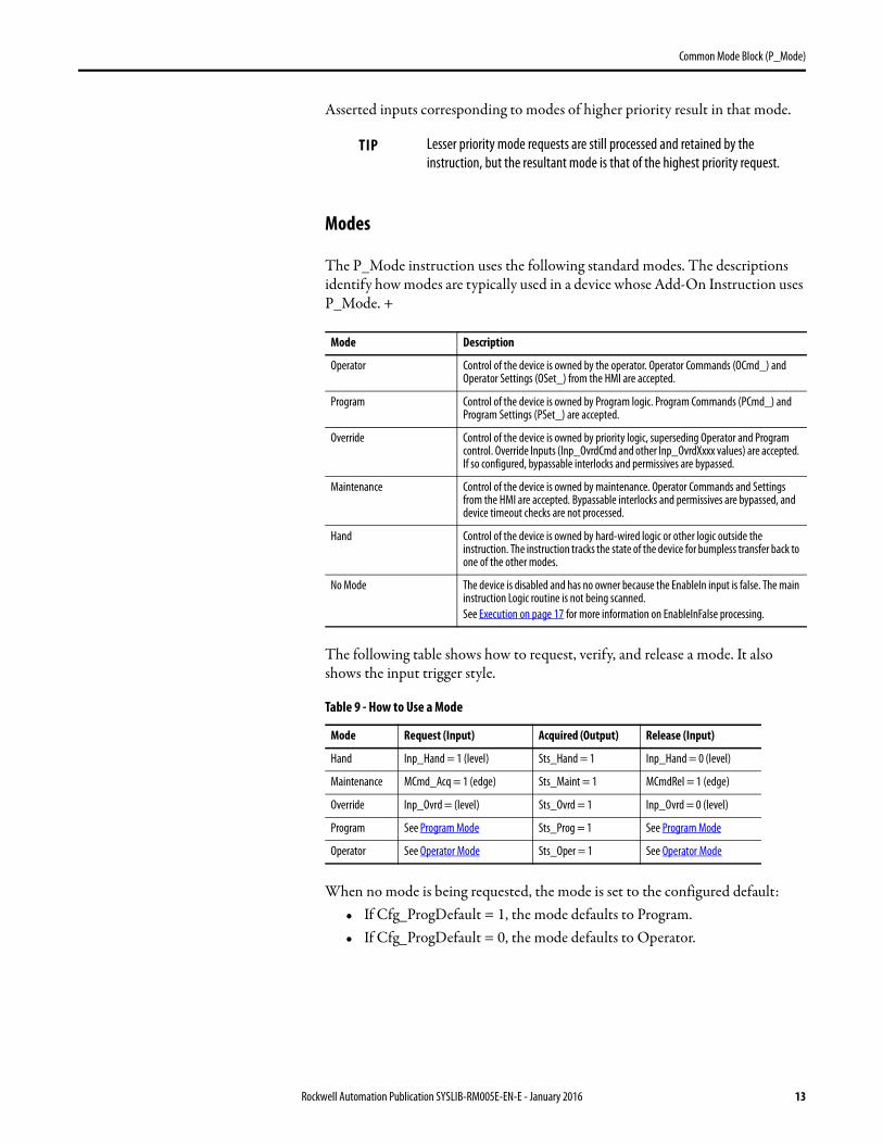
Asserted inputs corresponding to modes of higher priority result in that mode.
Modes
The P_Mode instruction uses the following standard modes. The descriptions identify how modes are typically used in a device whose Add-On Instruction uses P_Mode. +
The following table shows how to request, verify, and release a mode. It also shows the input trigger style.
When no mode is being requested, the mode is set to the configured default:• If Cfg_ProgDefault = 1, the mode defaults to Program.• If Cfg_ProgDefault = 0, the mode defaults to Operator.
TIP Lesser priority mode requests are still processed and retained by the instruction, but the resultant mode is that of the highest priority request.
Mode Description
Operator Control of the device is owned by the operator. Operator Commands (OCmd_) and Operator Settings (OSet_) from the HMI are accepted.
Program Control of the device is owned by Program logic. Program Commands (PCmd_) and Program Settings (PSet_) are accepted.
Override Control of the device is owned by priority logic, superseding Operator and Program control. Override Inputs (Inp_OvrdCmd and other Inp_OvrdXxxx values) are accepted. If so configured, bypassable interlocks and permissives are bypassed.
Maintenance Control of the device is owned by maintenance. Operator Commands and Settings from the HMI are accepted. Bypassable interlocks and permissives are bypassed, and device timeout checks are not processed.
Hand Control of the device is owned by hard-wired logic or other logic outside the instruction. The instruction tracks the state of the device for bumpless transfer back to one of the other modes.
No Mode The device is disabled and has no owner because the EnableIn input is false. The main instruction Logic routine is not being scanned.See Execution on page 17 for more information on EnableInFalse processing.
Table 9 - How to Use a Mode
Mode Request (Input) Acquired (Output) Release (Input)
Hand Inp_Hand = 1 (level) Sts_Hand = 1 Inp_Hand = 0 (level)
Maintenance MCmd_Acq = 1 (edge) Sts_Maint = 1 MCmdRel = 1 (edge)
Override Inp_Ovrd = (level) Sts_Ovrd = 1 Inp_Ovrd = 0 (level)
Program See Program Mode Sts_Prog = 1 See Program Mode
Operator See Operator Mode Sts_Oper = 1 See Operator Mode
Rockwell Automation Publication SYSLIB-RM005E-EN-E - January 2016 13
Common Mode Block (P_Mode)
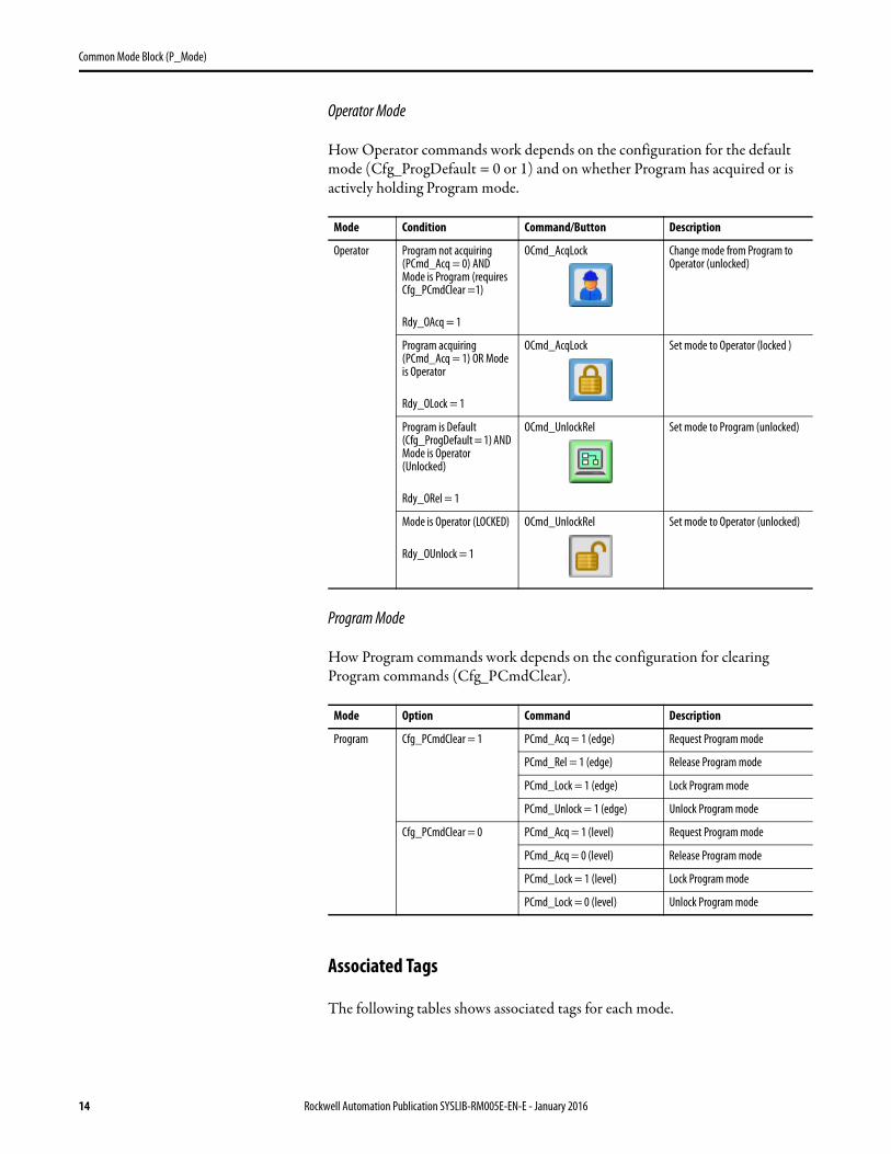
Operator Mode
How Operator commands work depends on the configuration for the default mode (Cfg_ProgDefault = 0 or 1) and on whether Program has acquired or is actively holding Program mode.
Program Mode
How Program commands work depends on the configuration for clearing Program commands (Cfg_PCmdClear).
Associated Tags
The following tables shows associated tags for each mode.
Mode Condition Command/Button Description
Operator Program not acquiring (PCmd_Acq = 0) AND Mode is Program (requires Cfg_PCmdClear =1)
Rdy_OAcq = 1
OCmd_AcqLock Change mode from Program to Operator (unlocked)
Program acquiring (PCmd_Acq = 1) OR Mode is Operator
Rdy_OLock = 1
OCmd_AcqLock Set mode to Operator (locked )
Program is Default (Cfg_ProgDefault = 1) AND Mode is Operator (Unlocked)
Rdy_ORel = 1
OCmd_UnlockRel Set mode to Program (unlocked)
Mode is Operator (LOCKED)
Rdy_OUnlock = 1
OCmd_UnlockRel Set mode to Operator (unlocked)
Mode Option Command Description
Program Cfg_PCmdClear = 1 PCmd_Acq = 1 (edge) Request Program mode
PCmd_Rel = 1 (edge) Release Program mode
PCmd_Lock = 1 (edge) Lock Program mode
PCmd_Unlock = 1 (edge) Unlock Program mode
Cfg_PCmdClear = 0 PCmd_Acq = 1 (level) Request Program mode
PCmd_Acq = 0 (level) Release Program mode
PCmd_Lock = 1 (level) Lock Program mode
PCmd_Lock = 0 (level) Unlock Program mode
14 Rockwell Automation Publication SYSLIB-RM005E-EN-E - January 2016
Common Mode Block (P_Mode)
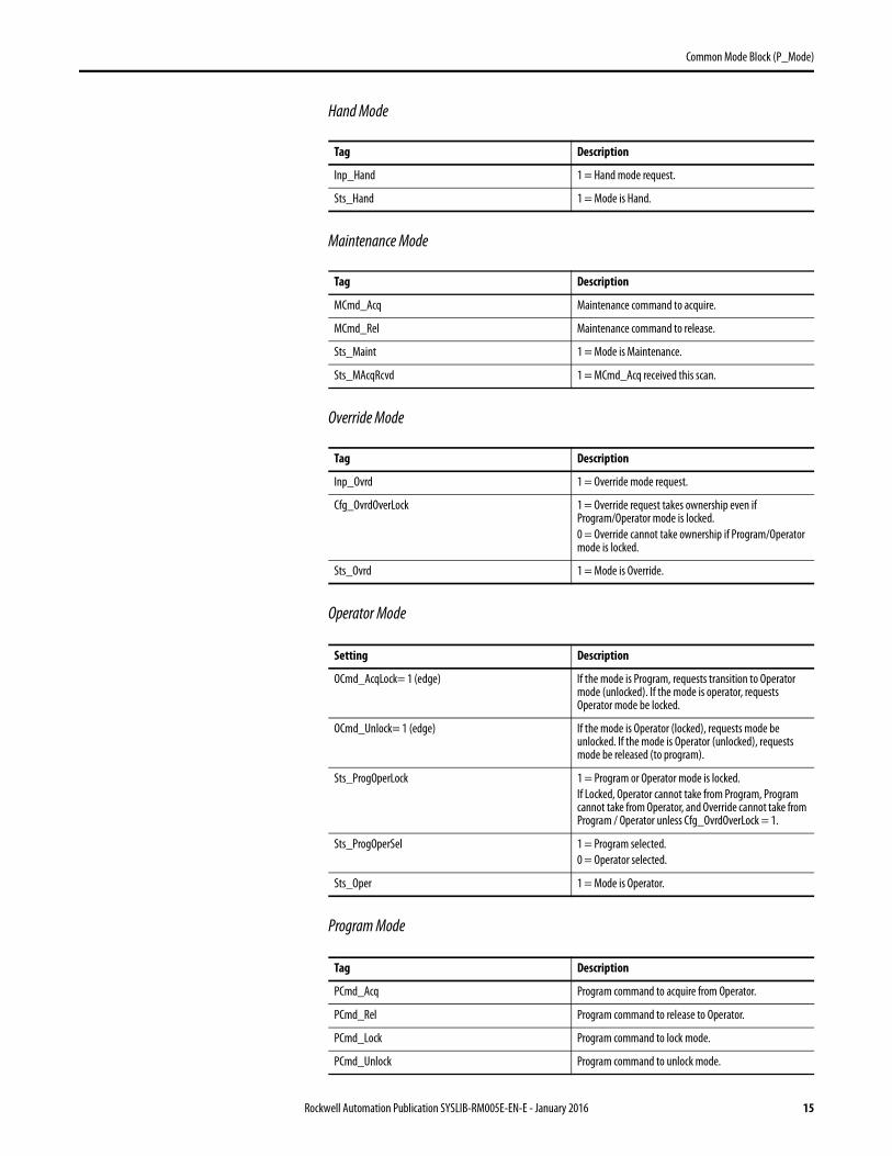
Hand Mode
Maintenance Mode
Override Mode
Operator Mode
Program Mode
Tag Description
Inp_Hand 1 = Hand mode request.
Sts_Hand 1 = Mode is Hand.
Tag Description
MCmd_Acq Maintenance command to acquire.
MCmd_Rel Maintenance command to release.
Sts_Maint 1 = Mode is Maintenance.
Sts_MAcqRcvd 1 = MCmd_Acq received this scan.
Tag Description
Inp_Ovrd 1 = Override mode request.
Cfg_OvrdOverLock 1 = Override request takes ownership even if Program/Operator mode is locked.0 = Override cannot take ownership if Program/Operator mode is locked.
Sts_Ovrd 1 = Mode is Override.
Setting Description
OCmd_AcqLock= 1 (edge) If the mode is Program, requests transition to Operator mode (unlocked). If the mode is operator, requests Operator mode be locked.
OCmd_Unlock= 1 (edge) If the mode is Operator (locked), requests mode be unlocked. If the mode is Operator (unlocked), requests mode be released (to program).
Sts_ProgOperLock 1 = Program or Operator mode is locked.If Locked, Operator cannot take from Program, Program cannot take from Operator, and Override cannot take from Program / Operator unless Cfg_OvrdOverLock = 1.
Sts_ProgOperSel 1 = Program selected.0 = Operator selected.
Sts_Oper 1 = Mode is Operator.
Tag Description
PCmd_Acq Program command to acquire from Operator.
PCmd_Rel Program command to release to Operator.
PCmd_Lock Program command to lock mode.
PCmd_Unlock Program command to unlock mode.
Rockwell Automation Publication SYSLIB-RM005E-EN-E - January 2016 15
Common Mode Block (P_Mode)
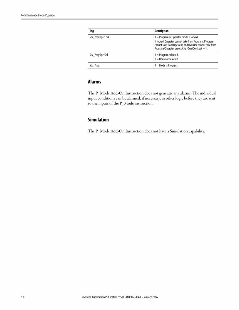
Alarms
The P_Mode Add-On Instruction does not generate any alarms. The individual input conditions can be alarmed, if necessary, in other logic before they are sent to the inputs of the P_Mode instruction.
Simulation
The P_Mode Add-On Instruction does not have a Simulation capability.
Sts_ProgOperLock 1 = Program or Operator mode is locked.If locked, Operator cannot take from Program, Program cannot take from Operator, and Override cannot take from Program/Operator unless Cfg_OvrdOverLock = 1.
Sts_ProgOperSel 1 = Program selected.0 = Operator selected.
Sts_Prog 1 = Mode is Program.
Tag Description
16 Rockwell Automation Publication SYSLIB-RM005E-EN-E - January 2016
Common Mode Block (P_Mode)
Execution
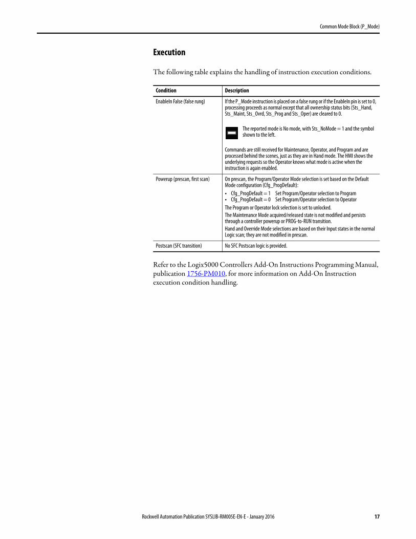
The following table explains the handling of instruction execution conditions.
Refer to the Logix5000 Controllers Add-On Instructions Programming Manual, publication 1756-PM010, for more information on Add-On Instruction execution condition handling.
Condition Description
EnableIn False (false rung) If the P_Mode instruction is placed on a false rung or if the EnableIn pin is set to 0, processing proceeds as normal except that all ownership status bits (Sts_Hand, Sts_Maint, Sts_Ovrd, Sts_Prog and Sts_Oper) are cleared to 0.
The reported mode is No mode, with Sts_NoMode = 1 and the symbol shown to the left.
Commands are still received for Maintenance, Operator, and Program and are processed behind the scenes, just as they are in Hand mode. The HMI shows the underlying requests so the Operator knows what mode is active when the instruction is again enabled.
Powerup (prescan, first scan) On prescan, the Program/Operator Mode selection is set based on the Default Mode configuration (Cfg_ProgDefault): • Cfg_ProgDefault = 1 Set Program/Operator selection to Program • Cfg_ProgDefault = 0 Set Program/Operator selection to Operator The Program or Operator lock selection is set to unlocked. The Maintenance Mode acquired/released state is not modified and persists through a controller powerup or PROG-to-RUN transition. Hand and Override Mode selections are based on their Input states in the normal Logic scan; they are not modified in prescan.
Postscan (SFC transition) No SFC Postscan logic is provided.
Rockwell Automation Publication SYSLIB-RM005E-EN-E - January 2016 17
Common Mode Block (P_Mode)
Display Elements There are no display elements or graphic symbols in P_Mode instruction.
This section describes the functions and displays for the P_Mode instruction that can appear on other faceplates.
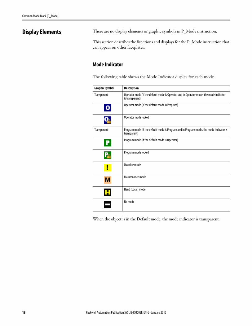
Mode Indicator
The following table shows the Mode Indicator display for each mode.
When the object is in the Default mode, the mode indicator is transparent.
Graphic Symbol Description
Transparent Operator mode (if the default mode is Operator and in Operator mode, the mode indicatoris transparent)
Operator mode (if the default mode is Program)
Operator mode locked
Transparent Program mode (if the default mode is Program and in Program mode, the mode indicator is transparent)
Program mode (if the default mode is Operator)
Program mode locked
Override mode
Maintenance mode
Hand (Local) mode
No mode
18 Rockwell Automation Publication SYSLIB-RM005E-EN-E - January 2016
Common Mode Block (P_Mode)
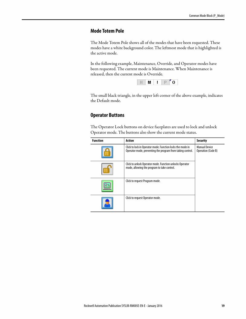
Mode Totem Pole
The Mode Totem Pole shows all of the modes that have been requested. These modes have a white background color. The leftmost mode that is highlighted is the active mode.
In the following example, Maintenance, Override, and Operator modes have been requested. The current mode is Maintenance. When Maintenance is released, then the current mode is Override.
The small black triangle, in the upper left corner of the above example, indicates the Default mode.
Operator Buttons
The Operator Lock buttons on device faceplates are used to lock and unlock Operator mode. The buttons also show the current mode status.
Function Action Security
Click to lock in Operator mode. Function locks the mode in Operator mode, preventing the program from taking control.
Manual Device Operation (Code B)
Click to unlock Operator mode. Function unlocks Operator mode, allowing the program to take control.
Click to request Program mode.
Click to request Operator mode.
Rockwell Automation Publication SYSLIB-RM005E-EN-E - January 2016 19
Common Mode Block (P_Mode)
Maintenance Buttons
The Maintenance buttons on device faceplates are used to request and release Maintenance mode.
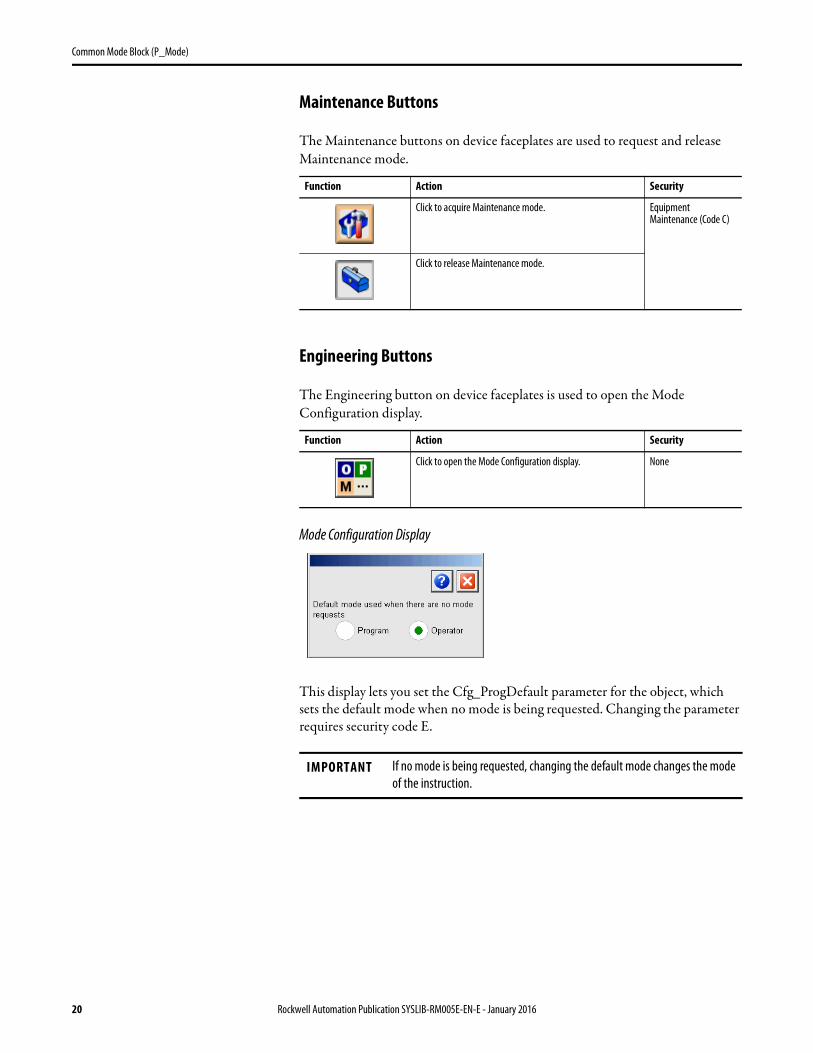
Engineering Buttons
The Engineering button on device faceplates is used to open the Mode Configuration display.
Mode Configuration Display
This display lets you set the Cfg_ProgDefault parameter for the object, which sets the default mode when no mode is being requested. Changing the parameter requires security code E.
Function Action Security
Click to acquire Maintenance mode. Equipment Maintenance (Code C)
Click to release Maintenance mode.
Function Action Security
Click to open the Mode Configuration display. None
IMPORTANT If no mode is being requested, changing the default mode changes the mode of the instruction.
20 Rockwell Automation Publication SYSLIB-RM005E-EN-E - January 2016
Common Mode Block (P_Mode)
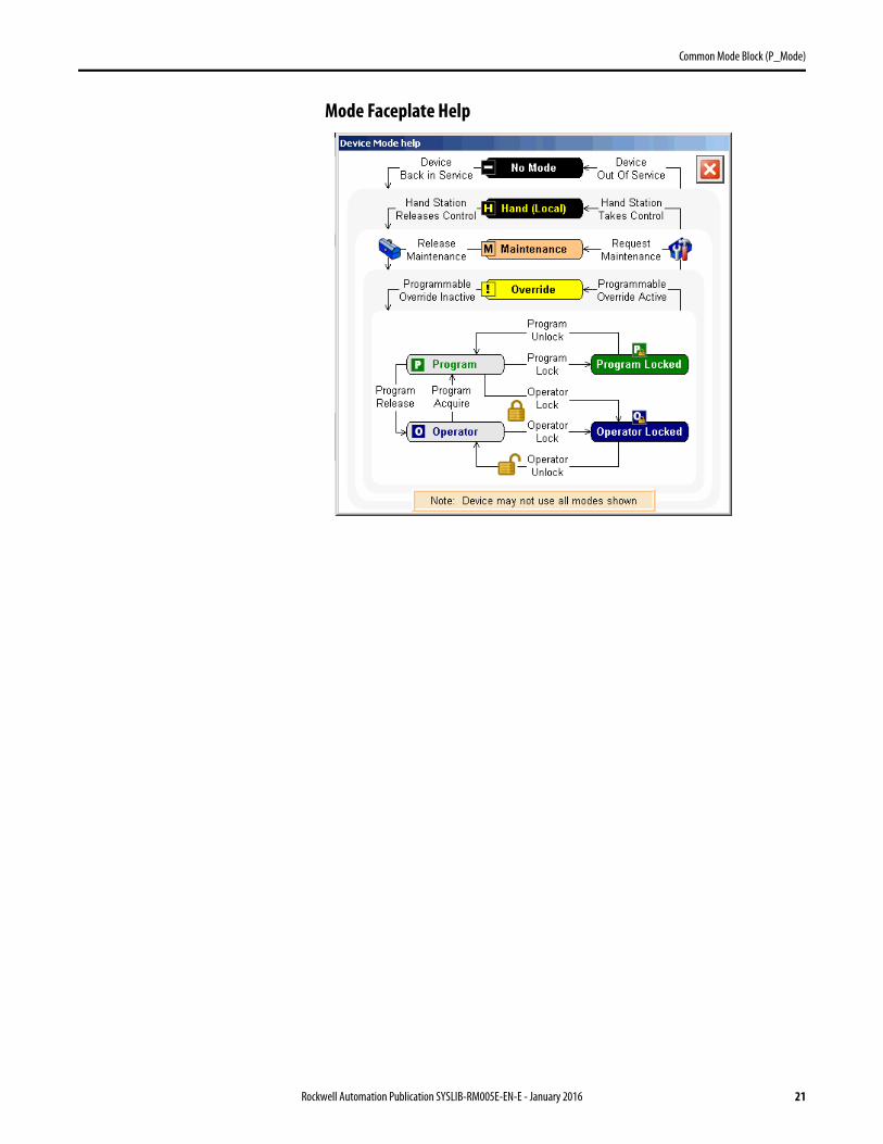
Mode Faceplate Help
Rockwell Automation Publication SYSLIB-RM005E-EN-E - January 2016 21
Common Mode Block (P_Mode)
Notes:
22 Rockwell Automation Publication SYSLIB-RM005E-EN-E - January 2016

Publication SYSLIB-RM005E-EN-E - January 2016Supersedes Publication SYSLIB-RM005D-EN-E - August 2014 Copyright © 2016 Rockwell Automation, Inc. All rights reserved. Printed in the U.S.A.
Rockwell Automation Support
Rockwell Automation provides technical information on the Web to assist you in using its products.At http://www.rockwellautomation.com/support you can find technical and application notes, sample code, and links to software service packs. You can also visit our Support Center at https://rockwellautomation.custhelp.com/ for software updates, support chats and forums, technical information, FAQs, and to sign up for product notification updates.
In addition, we offer multiple support programs for installation, configuration, and troubleshooting. For more information, contact your local distributor or Rockwell Automation representative, or visithttp://www.rockwellautomation.com/services/online-phone.
Installation Assistance
If you experience a problem within the first 24 hours of installation, review the information that is contained in this manual. You can contact Customer Support for initial help in getting your product up and running.
New Product Satisfaction Return
Rockwell Automation tests all of its products to help ensure that they are fully operational when shipped from the manufacturing facility. However, if your product is not functioning and needs to be returned, follow these procedures.
Documentation Feedback
Your comments will help us serve your documentation needs better. If you have any suggestions on how to improve this document, complete this form, publication RA-DU002, available at http://www.rockwellautomation.com/literature/.
United States or Canada 1.440.646.3434
Outside United States or Canada Use the Worldwide Locator at http://www.rockwellautomation.com/rockwellautomation/support/overview.page, or contact your local Rockwell Automation representative.
United States Contact your distributor. You must provide a Customer Support case number (call the phone number above to obtain one) to your distributor to complete the return process.
Outside United States Please contact your local Rockwell Automation representative for the return procedure.
Rockwell Otomasyon Ticaret A.Ş., Kar Plaza İş Merkezi E Blok Kat:6 34752 İçerenköy, İstanbul, Tel: +90 (216) 5698400
Rockwell Automation maintains current product environmental information on its website athttp://www.rockwellautomation.com/rockwellautomation/about-us/sustainability-ethics/product-environmental-compliance.page.