Embed Size (px)
Citation preview
ROBOTICS
Application manualPROFINET Controller/Device with IOConfigurator

Trace back information:Workspace R18-2 version a11Checked in 2018-10-11Skribenta version 5.3.008
Application manualPROFINET Controller/Device with IO Configurator
RobotWare 6.08
Document ID: 3HAC065546-001Revision: B
© Copyright 2018 ABB. All rights reserved.Specifications subject to change without notice.

The information in this manual is subject to change without notice and should notbe construed as a commitment by ABB. ABB assumes no responsibility for any errorsthat may appear in this manual.Except as may be expressly stated anywhere in this manual, nothing herein shall beconstrued as any kind of guarantee or warranty by ABB for losses, damages topersons or property, fitness for a specific purpose or the like.In no event shall ABB be liable for incidental or consequential damages arising fromuse of this manual and products described herein.This manual and parts thereof must not be reproduced or copied without ABB'swritten permission.Keep for future reference.Additional copies of this manual may be obtained from ABB.
Original instructions.
© Copyright 2018 ABB. All rights reserved.Specifications subject to change without notice.
ABB AB, RoboticsRobotics and MotionSe-721 68 Västerås
Sweden
Table of contents7Overview of this manual ...................................................................................................................9Product documentation ....................................................................................................................
11Safety ................................................................................................................................................12Network security ...............................................................................................................................13Terminology ......................................................................................................................................
151 Introduction151.1 What is PROFINET? ..........................................................................................161.2 PROFINET for IRC5 ...........................................................................................
192 Hardware overview192.1 Main computer ..................................................................................................262.2 Ethernet switches ..............................................................................................272.3 I/O devices .......................................................................................................
293 Software overview293.1 Information about the internal device ....................................................................313.2 Information about the internal controller ................................................................323.3 Software for configuring a device .........................................................................
334 The I/O Configurator user interface334.1 The user interface .............................................................................................354.2 The ribbon .......................................................................................................364.3 Configuration browser ........................................................................................394.4 Properties browser ............................................................................................404.5 Signal Editor ....................................................................................................414.6 Scan Editor ......................................................................................................
435 Configuring internal controller and external device using IO Configurator435.1 Configuring with IO Configurator ..........................................................................535.2 Using Fast Device Startup ...................................................................................
556 Configuring the internal device using IO Configurator (for option 997-2)
617 Configuring the internal device using IO Configurator (for option 997-1)
658 System parameters658.1 Introduction ......................................................................................................678.2 Type Industrial Network ......................................................................................678.2.1 Connection ............................................................................................688.2.2 PROFINET Station Name ..........................................................................698.3 Type PROFINET Device .....................................................................................698.3.1 PROFINET Station Name ..........................................................................708.3.2 Fast Device Startup .................................................................................718.3.3 Port 1 ....................................................................................................728.3.4 Port 2 ....................................................................................................738.3.5 Port 3 ....................................................................................................748.3.6 Port 4 ....................................................................................................758.3.7 Energy Saving ........................................................................................768.4 Type Signal ......................................................................................................768.4.1 Transfer To Device ..................................................................................778.4.2 Output Offset on Destination Device ...........................................................788.4.3 Transfer From Device ..............................................................................798.4.4 Input Offset on Source Device ...................................................................
Application manual - PROFINET Controller/Device with IO Configurator 53HAC065546-001 Revision: B
© Copyright 2018 ABB. All rights reserved.
Table of contents

808.5 Type PROFINET Internal Device ..........................................................................808.5.1 Input Size ..............................................................................................818.5.2 Output Size ............................................................................................
839 Troubleshooting839.1 Scenarios ........................................................................................................
89A ABB CI502 PROFINET I/O device
93Index
6 Application manual - PROFINET Controller/Device with IO Configurator3HAC065546-001 Revision: B
© Copyright 2018 ABB. All rights reserved.
Table of contents
Overview of this manualAbout this manual
This manual describes how to configure PROFINET for IRC5 using the tool IOConfigurator. IO Configurator is required to configure safe I/O modules. It is optionalto use it for general I/O modules, but alternative tools for configuring general I/Omodules are described in Application manual - PROFINET Controller/Device.This manual can be used for the following options:
• PROFIsafe F-Host and Device, option number 997-2 I
• PROFIsafe F-Device, option number 997-1 II
• Prepared for CI502, option number 1241-1 I (this option supports parts of the997-2 functionality)
I Also requires option 996-1 and 888-2.II Also requires option 996-1 and 888-2 or 888-3.
Note
Not all aspects of working with PROFINET is described in this manual. It may benecessary to also read Application manual - PROFINET Controller/Device.
UsageThis manual should be used during installation and configuration of the PROFINEToptions when using the tool IO Configurator.
Who should read this manual?This manual is intended for:
• Personnel that are responsible for installations and configurations of industrialnetwork hardware/software.
• Personnel that make the configurations of the I/O system.• System integrators.
PrerequisitesThe reader should have the required knowledge of:
• PROFINET network• I/O system• IRC5 controller• RobotStudio
References
ABB documents
Document IDReference
3HAC050948-001Technical reference manual - System parameters
3HAC047136-001Product manual - IRC5
3HAC050941-001Operating manual - IRC5 with FlexPendant
Continues on next pageApplication manual - PROFINET Controller/Device with IO Configurator 73HAC065546-001 Revision: B
© Copyright 2018 ABB. All rights reserved.
Overview of this manual
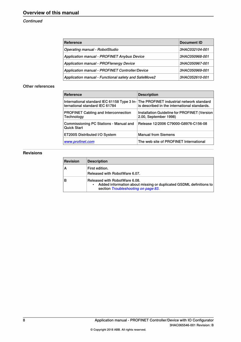
Document IDReference
3HAC032104-001Operating manual - RobotStudio
3HAC050968-001Application manual - PROFINET Anybus Device
3HAC050967-001Application manual - PROFIenergy Device
3HAC050969-001Application manual - PROFINET Controller/Device
3HAC052610-001Application manual - Functional safety and SafeMove2
Other references
DescriptionReference
The PROFINET industrial network standardis described in the international standards.
International standard IEC 61158 Type 3 In-ternational standard IEC 61784
Installation Guideline for PROFINET (Version2.00, September 1998)
PROFINET Cabling and InterconnectionTechnology
Release 12/2006 C79000-G8976-C156-08Commissioning PC Stations - Manual andQuick Start
Manual from SiemensET200S Distributed I/O System
The web site of PROFINET Internationalwww.profinet.com
Revisions
DescriptionRevision
First edition.AReleased with RobotWare 6.07.
Released with RobotWare 6.08.• Added information about missing or duplicated GSDML definitions to
section Troubleshooting on page 83.
B
8 Application manual - PROFINET Controller/Device with IO Configurator3HAC065546-001 Revision: B
© Copyright 2018 ABB. All rights reserved.
Overview of this manualContinued
Product documentationCategories for user documentation from ABB Robotics
The user documentation from ABB Robotics is divided into a number of categories.This listing is based on the type of information in the documents, regardless ofwhether the products are standard or optional.All documents can be found via myABB Business Portal, www.myportal.abb.com.
Product manualsManipulators, controllers, DressPack/SpotPack, and most other hardware isdelivered with a Product manual that generally contains:
• Safety information.• Installation and commissioning (descriptions of mechanical installation or
electrical connections).• Maintenance (descriptions of all required preventive maintenance procedures
including intervals and expected life time of parts).• Repair (descriptions of all recommended repair procedures including spare
parts).• Calibration.• Decommissioning.• Reference information (safety standards, unit conversions, screw joints, lists
of tools).• Spare parts list with corresponding figures (or references to separate spare
parts lists).• References to circuit diagrams.
Technical reference manualsThe technical reference manuals describe reference information for roboticsproducts, for example lubrication, the RAPID language, and system parameters.
Application manualsSpecific applications (for example software or hardware options) are described inApplication manuals. An application manual can describe one or severalapplications.An application manual generally contains information about:
• The purpose of the application (what it does and when it is useful).• What is included (for example cables, I/O boards, RAPID instructions, system
parameters, software).• How to install included or required hardware.• How to use the application.• Examples of how to use the application.
Continues on next pageApplication manual - PROFINET Controller/Device with IO Configurator 93HAC065546-001 Revision: B
© Copyright 2018 ABB. All rights reserved.
Product documentation

Operating manualsThe operating manuals describe hands-on handling of the products. The manualsare aimed at those having first-hand operational contact with the product, that isproduction cell operators, programmers, and troubleshooters.
10 Application manual - PROFINET Controller/Device with IO Configurator3HAC065546-001 Revision: B
© Copyright 2018 ABB. All rights reserved.
Product documentationContinued
SafetySafety of personnel
When working inside the robot controller it is necessary to be aware ofvoltage-related risks.A danger of high voltage is associated with the following parts:
• Devices inside the controller, for example I/O devices, can be supplied withpower from an external source.
• The mains supply/mains switch.• The power unit.• The power supply unit for the computer system (230 VAC).• The rectifier unit (400-480 VAC and 700 VDC). Capacitors!• The drive unit (700 VDC).• The service outlets (115/230 VAC).• The power supply unit for tools, or special power supply units for the
machining process.• The external voltage connected to the controller remains live even when the
robot is disconnected from the mains.• Additional connections.
Therefore, it is important that all safety regulations are followed when doingmechanical and electrical installation work.
Safety regulationsBefore beginning mechanical and/or electrical installations, ensure you are familiarwith the safety regulations described in Operating manual - General safetyinformation1 .
1 This manual contains all safety instructions from the product manuals for the manipulators and the controllers.
Application manual - PROFINET Controller/Device with IO Configurator 113HAC065546-001 Revision: B
© Copyright 2018 ABB. All rights reserved.
Safety

Network securityNetwork security
This product is designed to be connected to and to communicate information anddata via a network interface, It is your sole responsibility to provide and continuouslyensure a secure connection between the product and to your network or any othernetwork (as the case may be). You shall establish and maintain any appropriatemeasures (such as but not limited to the installation of firewalls, application ofauthentication measures, encryption of data, installation of anti-virus programs,etc) to protect the product, the network, its system and the interface against anykind of security breaches, unauthorized access, interference, intrusion, leakageand/or theft of data or information. ABB Ltd and its entities are not liable fordamages and/or losses related to such security breaches, any unauthorized access,interference, intrusion, leakage and/or theft of data or information.
12 Application manual - PROFINET Controller/Device with IO Configurator3HAC065546-001 Revision: B
© Copyright 2018 ABB. All rights reserved.
Network security
TerminologyTerms
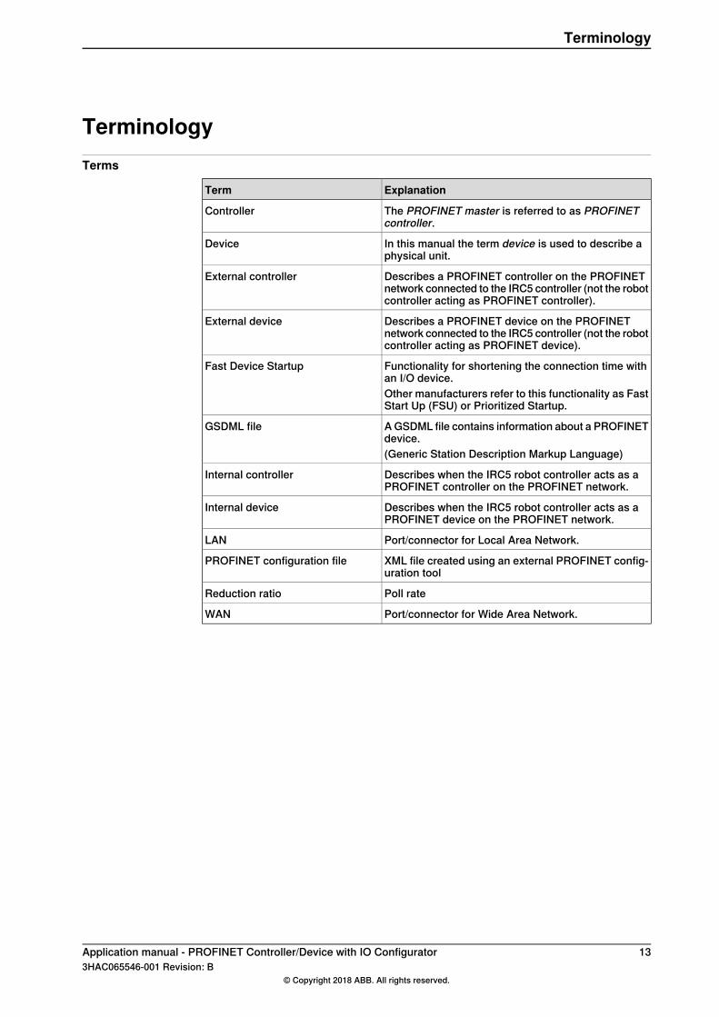
ExplanationTerm
The PROFINET master is referred to as PROFINETcontroller.
Controller
In this manual the term device is used to describe aphysical unit.
Device
Describes a PROFINET controller on the PROFINETnetwork connected to the IRC5 controller (not the robotcontroller acting as PROFINET controller).
External controller
Describes a PROFINET device on the PROFINETnetwork connected to the IRC5 controller (not the robotcontroller acting as PROFINET device).
External device
Functionality for shortening the connection time withan I/O device.
Fast Device Startup
Other manufacturers refer to this functionality as FastStart Up (FSU) or Prioritized Startup.
A GSDML file contains information about a PROFINETdevice.
GSDML file
(Generic Station Description Markup Language)
Describes when the IRC5 robot controller acts as aPROFINET controller on the PROFINET network.
Internal controller
Describes when the IRC5 robot controller acts as aPROFINET device on the PROFINET network.
Internal device
Port/connector for Local Area Network.LAN
XML file created using an external PROFINET config-uration tool
PROFINET configuration file
Poll rateReduction ratio
Port/connector for Wide Area Network.WAN
Application manual - PROFINET Controller/Device with IO Configurator 133HAC065546-001 Revision: B
© Copyright 2018 ABB. All rights reserved.
Terminology

This page is intentionally left blank
1 Introduction1.1 What is PROFINET?
GeneralPROFINET is an open standard for Industrial Ethernet. PROFINET satisfiesrequirements for automation technology. PROFINET solutions can be implementedfor factory and process automation, for safety applications, and for the entire rangeof drive technology right up to clock-synchronized motion control.
StandardizationThe use of open standards, simple operation, and the integration of existing systemsegments have driven the definition of PROFINET from the beginning. PROFINETis standardized in IEC 61158 and IEC 61784. The continual further developmentof PROFINET offers users a long term perspective for the implementation of theirautomation tasks.
Communication profilesPROFINET has a modular design and different PROFINET communication profilesare all combinations of modular elements from the groups transmission technology,communication protocol, and application profiles.Here are some examples of PROFINET communication profiles:
• PROFINET-IO - Distributed I/O (Remote I/O). Here, the familiar I/O view ofPROFIBUS is retained, in which the user data from the field devices areperiodically transmitted into the process model of the control system.
• PROFINET-CBA - Based on the object-oriented modelling of technologicalmodules. Based on the object model, machines and installations arestructured in PROFINET in the form of technological modules.
• PROFIsafe - Defines how safety-oriented devices (emergency shutoffswitches, light grids, overfill protection systems, etc.) can communicatesafety control information over a network securely enough that they can beused in safety-oriented automation tasks up to EN954's KAT4, AK6, or SIL3(Safety Integrity Level).
• PROFIdrive - The PROFIdrive profile covers application scenarios from simplefrequency converters to highly dynamic servo drivers.
• PROFIenergy - A profile of the PROFINET communications protocol thatallows the power consumption of automation equipment in manufacturing(such as robot assembly cells, laser cutters and sub-systems such as paintlines) to be managed over a PROFINET network. It offers an open andstandardized means of controlling energy usage during planned andunplanned breaks in production. See alsoApplicationmanual - PROFIenergyDevice.
Application manual - PROFINET Controller/Device with IO Configurator 153HAC065546-001 Revision: B
© Copyright 2018 ABB. All rights reserved.
1 Introduction1.1 What is PROFINET?
1.2 PROFINET for IRC5
GeneralThe PROFINET network is running on the IRC5 main computer and does not requireany additional hardware. PROFINET as described in this manual requires maincomputer DSQC1000 or newer (e.g. DSQC1018).
OptionsWith optionPROFINETController/Device, the IRC5 controller can act as a controller,device, or both on the PROFINET network.With option PROFINET Device, the IRC5 controller can only act as a device.
Tip
If only PROFINET device functionality is required, then the option PROFINETAnybus Device can also be used.For more information see Application manual - PROFINET Anybus Device.
Note
Note that the network settings are set for the Connection, i.e. the physicalconnector on the main computer used for the PROFINET network.This means that the network settings are shared between the internal device andthe internal controller if the IRC5 controller acts as both on the PROFINETnetwork. This is also the interface used when scanning the network for PROFINETdevices, using the scan editor.
CompatibilityFor RobotWare 6.06 and later, the PROFINET device is certified by PROFIBUS &PROFINET International (PI) with conformance class B/ NetLoad Class II and thedevice profiles; PROFIenergy and PROFIsafe.PROFINET device is certified for the PROFINET version 2.33.
Specification overview, internal controller
SpecificationItem
Maximum 50 I/O devicesNumber of I/O devices connected to control-ler
Maximum 256 input bytes and 256 outputbytes per device.
Connection size
Specification overview, internal device
SpecificationItem
See GSDML file on page 29.GSDML file
2.33PROFINET Version
Continues on next page16 Application manual - PROFINET Controller/Device with IO Configurator
3HAC065546-001 Revision: B© Copyright 2018 ABB. All rights reserved.
1 Introduction1.2 PROFINET for IRC5
SpecificationItem
Slot 1-4: Digital input or output modules ofvariable size
Slot configuration
Maximum 256 input bytes and 256 outputbytes per device.
Connection size
Default gatewayThere are multiple default gateways in the system. And hence, it is possible tohave two different default gateways in the system, one for the non-PROFINETtraffic and one that only manages the PROFINET interface and its traffic. So whileusing optionPROFINETController/Device the LAN 3 port is used only for PROFINETtraffic.
Device replacementPROFINET controller supports the device replacement mechanism. When a devicefails, a new, identical device can replace the failed one if plugged in the sametopology location. And this does not need any engineering tool. The new deviceis automatically assigned the same parameters and name as the previous one.The conditions for device replacement to work are:
• You must replace a previously connected device by an identical device withan empty station name at the same topology location. For example, the newdevice is plugged in the same port as previously in a switch.
• This feature requires all switches and devices to support Link Layer DiscoveryProtocol (LLDP). The easiest way to achieve this is to only use ConformanceClass B devices and switches in the PROFINET network.
Application manual - PROFINET Controller/Device with IO Configurator 173HAC065546-001 Revision: B
© Copyright 2018 ABB. All rights reserved.
1 Introduction1.2 PROFINET for IRC5
Continued

This page is intentionally left blank
2 Hardware overview2.1 Main computer
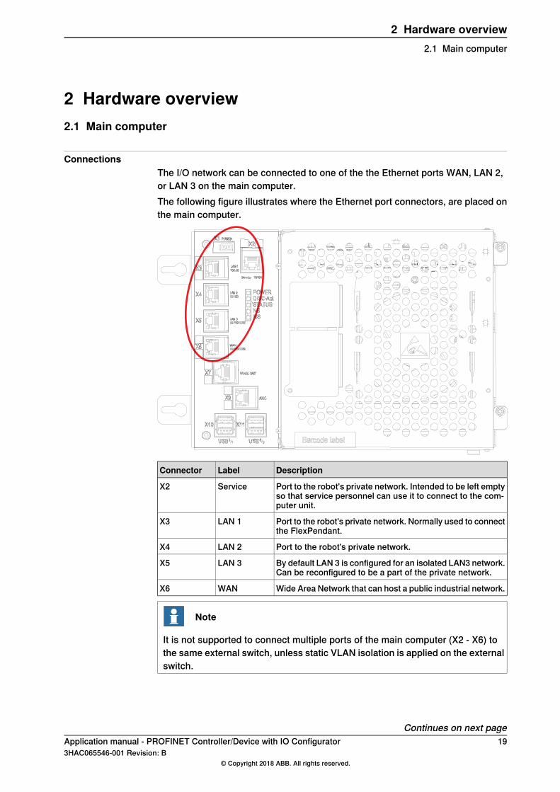
ConnectionsThe I/O network can be connected to one of the the Ethernet ports WAN, LAN 2,or LAN 3 on the main computer.The following figure illustrates where the Ethernet port connectors, are placed onthe main computer.
DescriptionLabelConnector
Port to the robot's private network. Intended to be left emptyso that service personnel can use it to connect to the com-puter unit.
ServiceX2
Port to the robot's private network. Normally used to connectthe FlexPendant.
LAN 1X3
Port to the robot's private network.LAN 2X4
By default LAN 3 is configured for an isolated LAN3 network.Can be reconfigured to be a part of the private network.
LAN 3X5
Wide Area Network that can host a public industrial network.WANX6
Note
It is not supported to connect multiple ports of the main computer (X2 - X6) tothe same external switch, unless static VLAN isolation is applied on the externalswitch.
Continues on next pageApplication manual - PROFINET Controller/Device with IO Configurator 193HAC065546-001 Revision: B
© Copyright 2018 ABB. All rights reserved.
2 Hardware overview2.1 Main computer
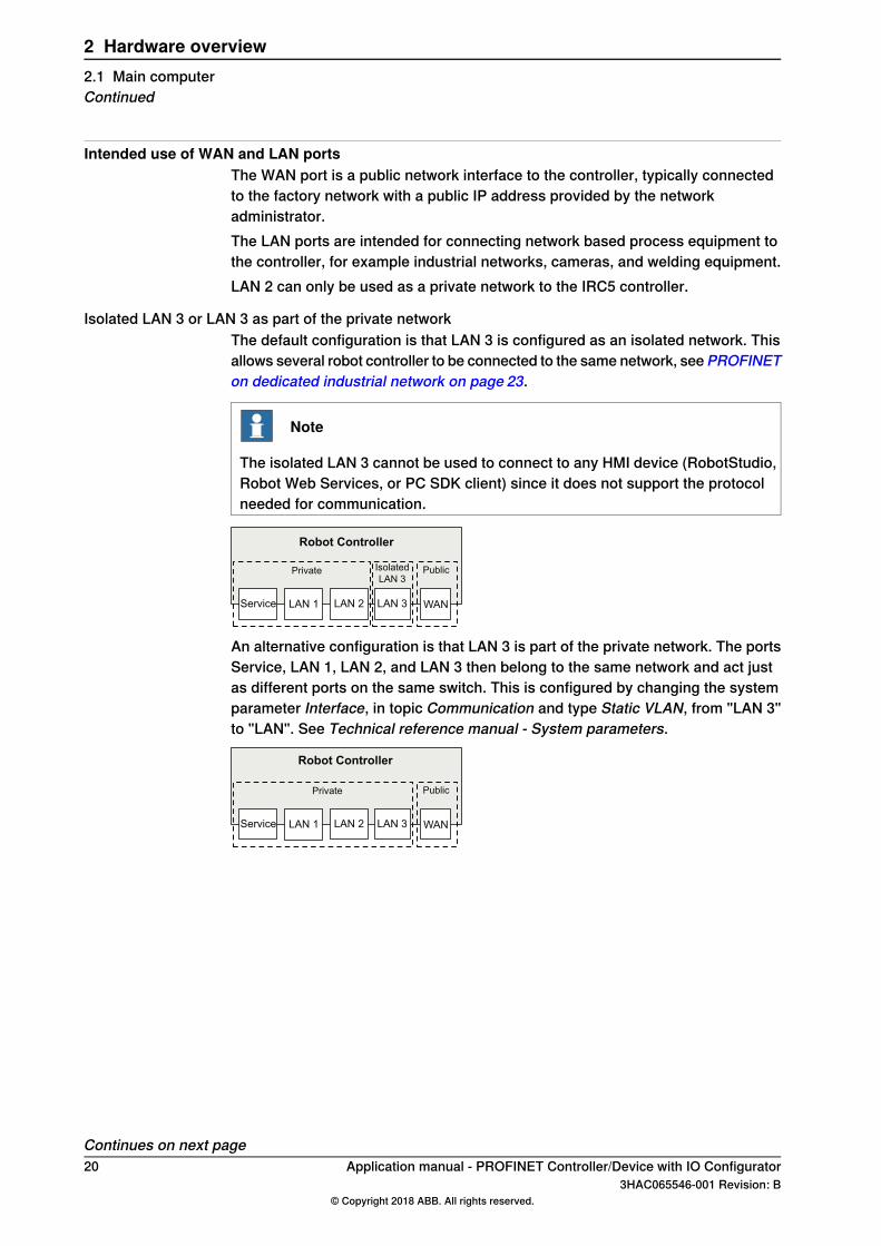
Intended use of WAN and LAN portsThe WAN port is a public network interface to the controller, typically connectedto the factory network with a public IP address provided by the networkadministrator.The LAN ports are intended for connecting network based process equipment tothe controller, for example industrial networks, cameras, and welding equipment.LAN 2 can only be used as a private network to the IRC5 controller.
Isolated LAN 3 or LAN 3 as part of the private networkThe default configuration is that LAN 3 is configured as an isolated network. Thisallows several robot controller to be connected to the same network, seePROFINETon dedicated industrial network on page 23.
Note
The isolated LAN 3 cannot be used to connect to any HMI device (RobotStudio,Robot Web Services, or PC SDK client) since it does not support the protocolneeded for communication.
WANLAN 2 LAN 3
Private
Robot Controller
LAN 1Service
PublicIsolated
LAN 3
An alternative configuration is that LAN 3 is part of the private network. The portsService, LAN 1, LAN 2, and LAN 3 then belong to the same network and act justas different ports on the same switch. This is configured by changing the systemparameter Interface, in topic Communication and type Static VLAN, from "LAN 3"to "LAN". See Technical reference manual - System parameters.
WANLAN 2 LAN 3
Private
LAN 1Service
Public
Robot Controller
Continues on next page20 Application manual - PROFINET Controller/Device with IO Configurator
3HAC065546-001 Revision: B© Copyright 2018 ABB. All rights reserved.
2 Hardware overview2.1 Main computerContinued
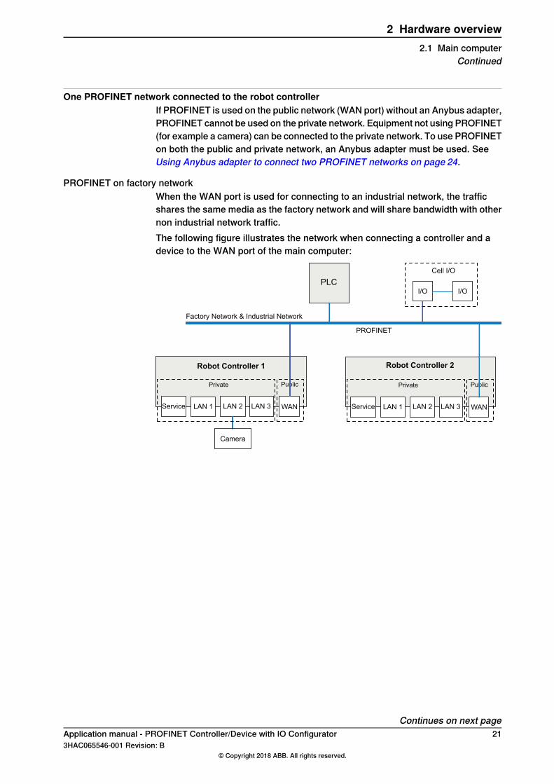
One PROFINET network connected to the robot controllerIf PROFINET is used on the public network (WAN port) without an Anybus adapter,PROFINET cannot be used on the private network. Equipment not using PROFINET(for example a camera) can be connected to the private network. To use PROFINETon both the public and private network, an Anybus adapter must be used. SeeUsing Anybus adapter to connect two PROFINET networks on page 24.
PROFINET on factory networkWhen the WAN port is used for connecting to an industrial network, the trafficshares the same media as the factory network and will share bandwidth with othernon industrial network traffic.The following figure illustrates the network when connecting a controller and adevice to the WAN port of the main computer:
WANLAN 2 LAN 3
Private
LAN 1Service
Public
WAN
Factory Network & Industrial Network
LAN 2 LAN 3
Private
Robot Controller 1
LAN 1Service
Robot Controller 2
PLC
Camera
Public
Cell I/O
I/OI/O
PROFINET
Continues on next pageApplication manual - PROFINET Controller/Device with IO Configurator 213HAC065546-001 Revision: B
© Copyright 2018 ABB. All rights reserved.
2 Hardware overview2.1 Main computer
Continued
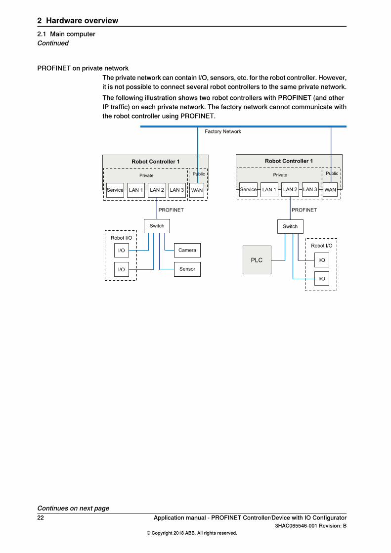
PROFINET on private networkThe private network can contain I/O, sensors, etc. for the robot controller. However,it is not possible to connect several robot controllers to the same private network.The following illustration shows two robot controllers with PROFINET (and otherIP traffic) on each private network. The factory network cannot communicate withthe robot controller using PROFINET.
Factory Network
Robot I/O
I/O
Switch
Robot I/O
I/O
I/O
I/O
Switch
Sensor
Camera
WANLAN 2 LAN 3
Private
Robot Controller 1
LAN 1Service
Public
WANLAN 2 LAN 3
Private
Robot Controller 1
LAN 1Service
Public
PLC
PROFINET PROFINET
Continues on next page22 Application manual - PROFINET Controller/Device with IO Configurator
3HAC065546-001 Revision: B© Copyright 2018 ABB. All rights reserved.
2 Hardware overview2.1 Main computerContinued
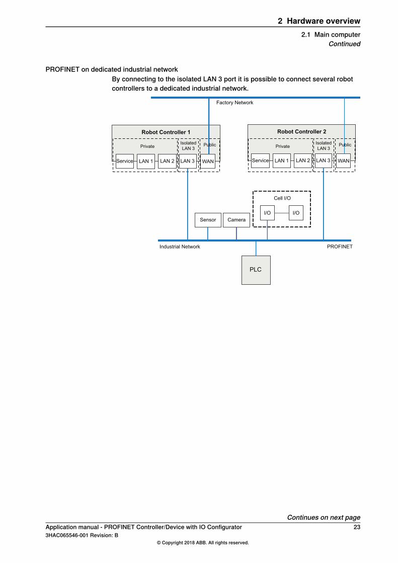
PROFINET on dedicated industrial networkBy connecting to the isolated LAN 3 port it is possible to connect several robotcontrollers to a dedicated industrial network.
WAN
Factory Network
LAN 2 LAN 3
Private
Robot Controller 1
LAN 1Service WANLAN 2 LAN 3
Robot Controller 2
LAN 1Service
PLC
Sensor
Cell I/O
I/OI/O
Industrial Network
Isolated
LAN 3Public Private
Isolated
LAN 3Public
Camera
PROFINET
Continues on next pageApplication manual - PROFINET Controller/Device with IO Configurator 233HAC065546-001 Revision: B
© Copyright 2018 ABB. All rights reserved.
2 Hardware overview2.1 Main computer
Continued
Using Anybus adapter to connect two PROFINET networks
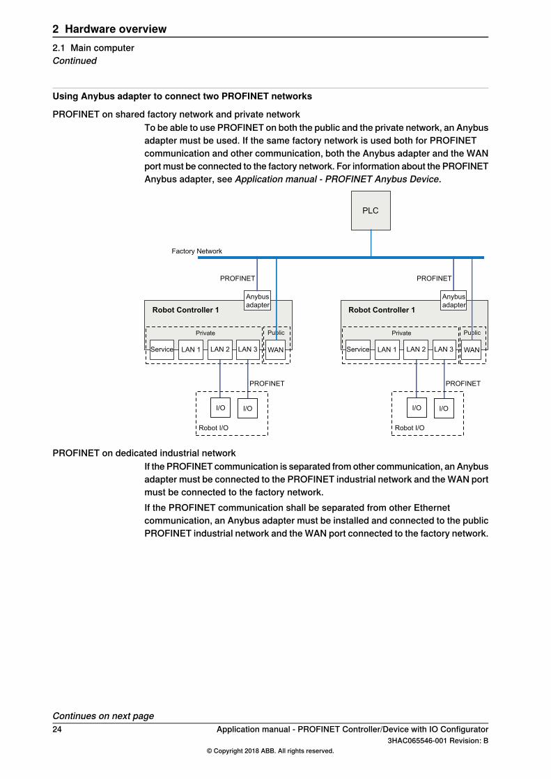
PROFINET on shared factory network and private networkTo be able to use PROFINET on both the public and the private network, an Anybusadapter must be used. If the same factory network is used both for PROFINETcommunication and other communication, both the Anybus adapter and the WANport must be connected to the factory network. For information about the PROFINETAnybus adapter, see Application manual - PROFINET Anybus Device.
WAN
Factory Network
Private
Robot Controller 1
LAN 1Service
PLC
Robot I/O
LAN 2 LAN 3
I/O I/O
Anybus
adapter
WAN
Private
Robot Controller 1
LAN 1Service
Robot I/O
LAN 2 LAN 3
I/O I/O
Public Public
Anybus
adapter
PROFINET PROFINET
PROFINET PROFINET
PROFINET on dedicated industrial networkIf the PROFINET communication is separated from other communication, an Anybusadapter must be connected to the PROFINET industrial network and the WAN portmust be connected to the factory network.If the PROFINET communication shall be separated from other Ethernetcommunication, an Anybus adapter must be installed and connected to the publicPROFINET industrial network and the WAN port connected to the factory network.
Continues on next page24 Application manual - PROFINET Controller/Device with IO Configurator
3HAC065546-001 Revision: B© Copyright 2018 ABB. All rights reserved.
2 Hardware overview2.1 Main computerContinued
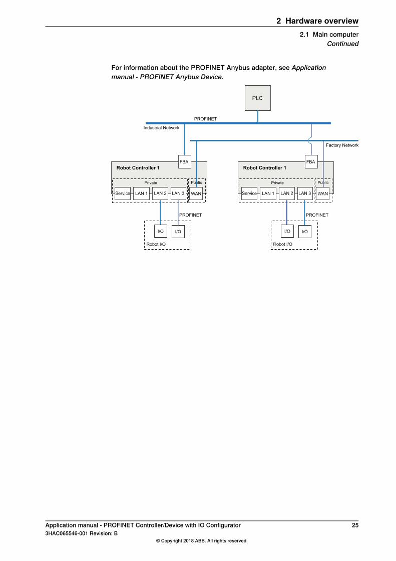
For information about the PROFINET Anybus adapter, see Applicationmanual - PROFINET Anybus Device.
WAN
Factory Network
Private
Robot Controller 1
LAN 1Service
PLC
Robot I/O
LAN 2 LAN 3
I/O I/O
FBA
WAN
Private
Robot Controller 1
LAN 1Service
Robot I/O
LAN 2 LAN 3
I/O I/O
Public Public
Industrial Network
FBA
PROFINET
PROFINET PROFINET
Application manual - PROFINET Controller/Device with IO Configurator 253HAC065546-001 Revision: B
© Copyright 2018 ABB. All rights reserved.
2 Hardware overview2.1 Main computer
Continued
2.2 Ethernet switches
PrerequisitesIt is recommended that switches used in the I/O network support Quality of Service(QoS).I/O devices mark their packets with a priority value. The priority value is used inorder to get better I/O data throughput and shorter delays on the network.Switches and routers are then able to differentiate the device's critical from theother non-critical traffic. To do this, the switches and routers must support Qualityof Service.
26 Application manual - PROFINET Controller/Device with IO Configurator3HAC065546-001 Revision: B
© Copyright 2018 ABB. All rights reserved.
2 Hardware overview2.2 Ethernet switches

2.3 I/O devices
LimitationsIt is possible to connect any type of PROFINET-IO compliant I/O device on thePROFINET controller network. All I/O devices should comply with the PROFINETstandard and be conformance tested by PROFINET international. I/O devices maybe mounted inside the IRC5 controller.
Safety I/O devicesPROFINET network supports safety module. It is possible to configure safety I/Odevices and create safety signals to the I/O devices. For more information, referto Application manual - Functional safety and SafeMove2 and Applicationmanual - I/O Configurator.
Application manual - PROFINET Controller/Device with IO Configurator 273HAC065546-001 Revision: B
© Copyright 2018 ABB. All rights reserved.
2 Hardware overview2.3 I/O devices

This page is intentionally left blank
3 Software overview3.1 Information about the internal device
GeneralTo use the PROFINET internal device, the IRC5 controller must be installed witheither the option 888-2 PROFINET Controller/Device or 888-3 PROFINET Device.The PROFINET internal device can be used to:
• connect a PLC to the IRC5 controller.• connect the IRC5 controller to another IRC5 controller which acts as a master.
Predefined networkWhen the robot system is installed with thePROFINET option, a predefined networkwith the name PROFINET is created at system startup.Use RobotStudio or other recommended tool to configure the PROFINET networkfor initial use. For example, by setting the correct network name and IP settings.
Predefined internal deviceWhen the robot system is installed with the PROFINET option, a predefined internaldevice with the name PN_Internal_Device is created at system startup.It is used to define the internal device in the IRC5 controller, which will enable aPLC to connect to the IRC5 controller. There can only be one internal device definedin the IRC5 controller.
GSDML fileIn order to configure a PROFINET network with an external PROFINET configurationtool, a GSDML file for each I/O device needs to be imported into the tool. Thesefiles contains vital information about the PROFINET I/O devices and they shall besupplied by the vendor/manufacturer of the specific PROFINET module.For information on where to find the GSDML file for the IRC5 controller, see Locationof GSDML files on page 32.
Template I/O configuration fileA template I/O configuration file is available for the internal device. The file containspreconfigured names for all available inputs and outputs. The file can be loadedto the controller, using RobotStudio or the FlexPendant, to facilitate and speed upthe configuration.The I/O template configuration file, PN_Internal_Device.cfg, can be obtained fromRobotStudio or the IRC5 controller.
• In the RobotWare installation folder in RobotStudio: ...\RobotPackages\RobotWare_RPK_<version>\utility\service\ioconfig\PROFINET\
• On the IRC5 Controller: <SystemName>\PRODUCTS\<RobotWare_xx.xx.xxxx>\utility\service\ioconfig\PROFINET\
Continues on next pageApplication manual - PROFINET Controller/Device with IO Configurator 293HAC065546-001 Revision: B
© Copyright 2018 ABB. All rights reserved.
3 Software overview3.1 Information about the internal device
Note
Navigate to the RobotWare installation folder from the RobotStudio Add-Ins tab,by right-clicking on the installed RobotWare version in the Add-Ins browser andselecting Open Package Folder.
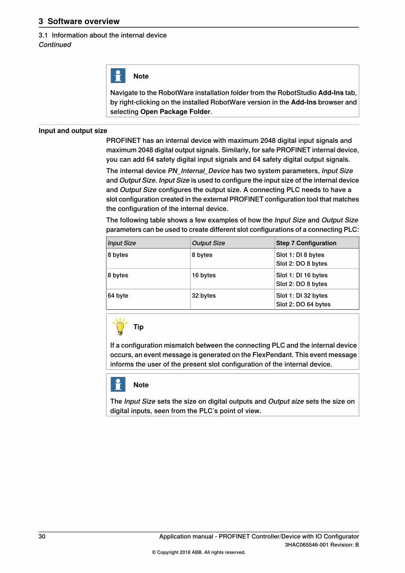
Input and output sizePROFINET has an internal device with maximum 2048 digital input signals andmaximum 2048 digital output signals. Similarly, for safe PROFINET internal device,you can add 64 safety digital input signals and 64 safety digital output signals.The internal device PN_Internal_Device has two system parameters, Input Sizeand Output Size. Input Size is used to configure the input size of the internal deviceand Output Size configures the output size. A connecting PLC needs to have aslot configuration created in the external PROFINET configuration tool that matchesthe configuration of the internal device.The following table shows a few examples of how the Input Size and Output Sizeparameters can be used to create different slot configurations of a connecting PLC:
Step 7 ConfigurationOutput SizeInput Size
Slot 1: DI 8 bytes8 bytes8 bytesSlot 2: DO 8 bytes
Slot 1: DI 16 bytes16 bytes8 bytesSlot 2: DO 8 bytes
Slot 1: DI 32 bytes32 bytes64 byteSlot 2: DO 64 bytes
Tip
If a configuration mismatch between the connecting PLC and the internal deviceoccurs, an event message is generated on the FlexPendant. This event messageinforms the user of the present slot configuration of the internal device.
Note
The Input Size sets the size on digital outputs and Output size sets the size ondigital inputs, seen from the PLC’s point of view.
30 Application manual - PROFINET Controller/Device with IO Configurator3HAC065546-001 Revision: B
© Copyright 2018 ABB. All rights reserved.
3 Software overview3.1 Information about the internal deviceContinued
3.2 Information about the internal controller
GeneralTo use the PROFINET internal controller, the IRC5 controller must be installed withthe option PROFINET Controller/Device.The PROFINET internal controller can be used to:
• connect PROFINET devices to the IRC5 controller.• connect the IRC5 controller to another IRC5 controller which acts as a device.
GSDML filesIn order to configure a PROFINET network with an external PROFINET configurationtool, GSDML files need to be imported into the tool. These files contains vitalinformation about the PROFINET I/O devices and they shall be supplied by thevendor/manufacturer of the specific PROFINET module.
Application manual - PROFINET Controller/Device with IO Configurator 313HAC065546-001 Revision: B
© Copyright 2018 ABB. All rights reserved.
3 Software overview3.2 Information about the internal controller

3.3 Software for configuring a device
GeneralThe PROFINET internal device does not need any type of PC software to beactivated, but the connecting PLC / PROFINET controller might need a PC softwaretool to configure all connection parameters used to connect to the IRC5 system.
Location of GSDML filesGSDML files are stored under the <system>/HOME/GSDML catalog of the targetsystem.
32 Application manual - PROFINET Controller/Device with IO Configurator3HAC065546-001 Revision: B
© Copyright 2018 ABB. All rights reserved.
3 Software overview3.3 Software for configuring a device
4 The I/O Configurator user interface4.1 The user interface
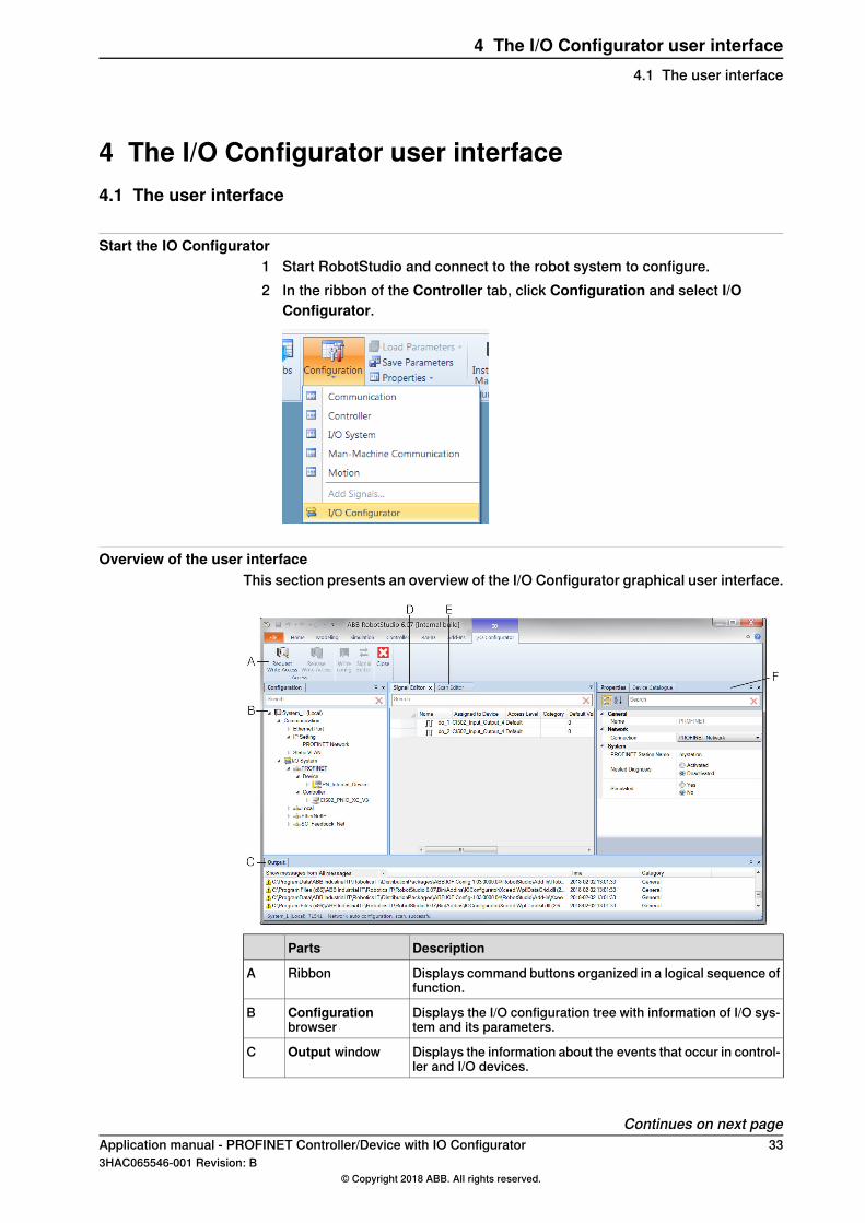
Start the IO Configurator1 Start RobotStudio and connect to the robot system to configure.2 In the ribbon of the Controller tab, click Configuration and select I/O
Configurator.
Overview of the user interfaceThis section presents an overview of the I/O Configurator graphical user interface.
DescriptionParts
Displays command buttons organized in a logical sequence offunction.
RibbonA
Displays the I/O configuration tree with information of I/O sys-tem and its parameters.
Configurationbrowser
B
Displays the information about the events that occur in control-ler and I/O devices.
Output windowC
Continues on next pageApplication manual - PROFINET Controller/Device with IO Configurator 333HAC065546-001 Revision: B
© Copyright 2018 ABB. All rights reserved.
4 The I/O Configurator user interface4.1 The user interface

DescriptionParts
Displays the signals assigned to the I/O device. Enables to addor delete signals of I/O device.
Signal EditorD
Displays the information of the I/O devices that are found onthe network.
Scan EditorE
Displays all available properties and settings of the selectedI/O device or Configuration nodes. The following tabs areavailable:
• Properties tab - displays the properties of the selectedI/O device.
• Device Catalogue tab - displays the device cataloguesused for configuring the I/O devices.
Properties browserF
34 Application manual - PROFINET Controller/Device with IO Configurator3HAC065546-001 Revision: B
© Copyright 2018 ABB. All rights reserved.
4 The I/O Configurator user interface4.1 The user interfaceContinued
4.2 The ribbon
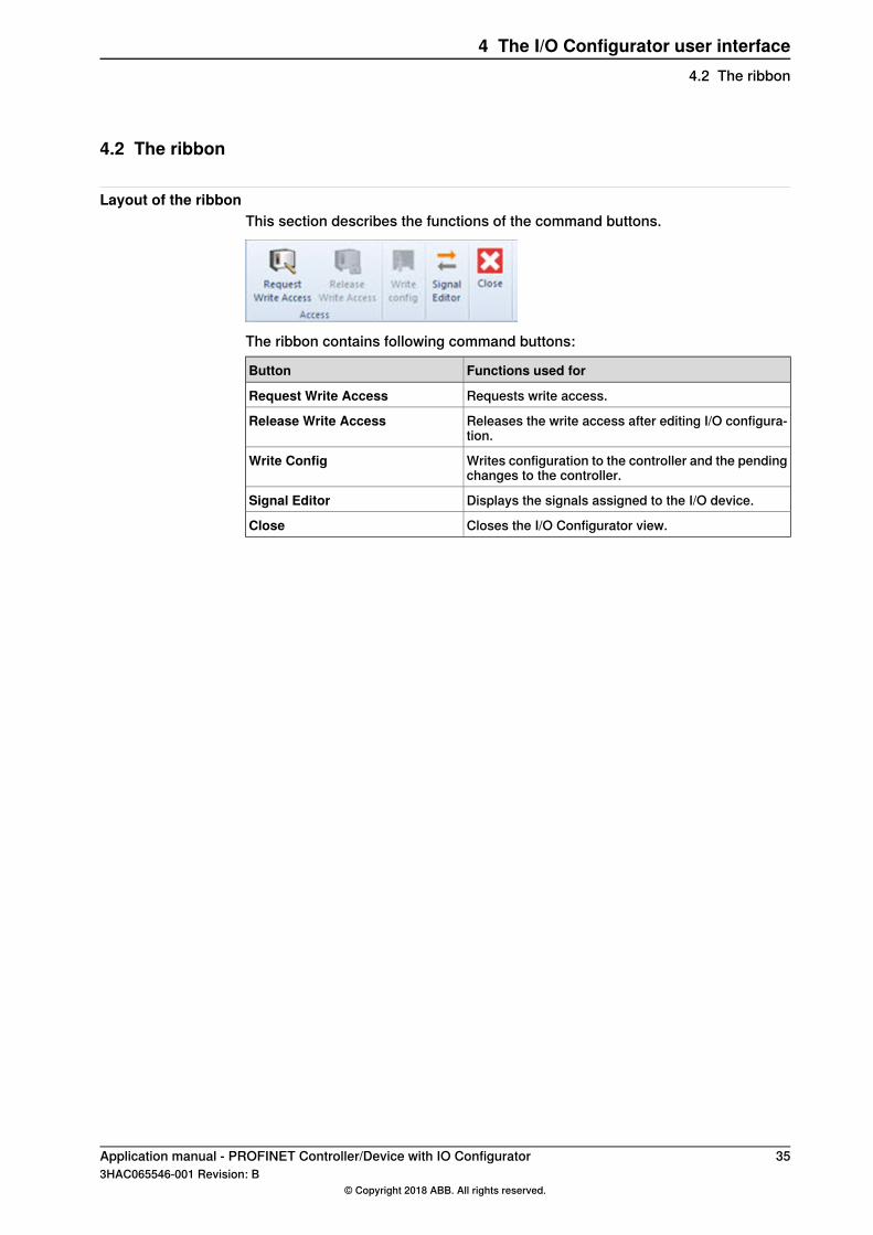
Layout of the ribbonThis section describes the functions of the command buttons.
The ribbon contains following command buttons:
Functions used forButton
Requests write access.Request Write Access
Releases the write access after editing I/O configura-tion.
Release Write Access
Writes configuration to the controller and the pendingchanges to the controller.
Write Config
Displays the signals assigned to the I/O device.Signal Editor
Closes the I/O Configurator view.Close
Application manual - PROFINET Controller/Device with IO Configurator 353HAC065546-001 Revision: B
© Copyright 2018 ABB. All rights reserved.
4 The I/O Configurator user interface4.2 The ribbon
4.3 Configuration browser
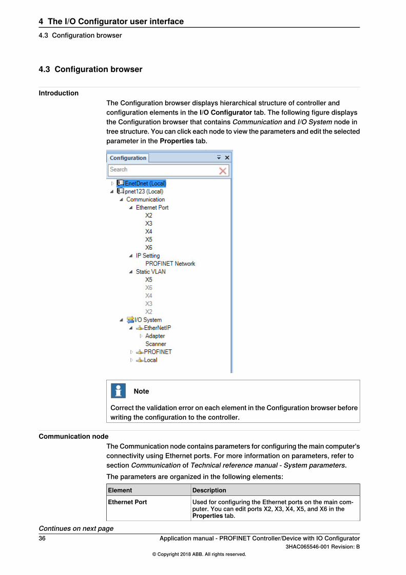
IntroductionThe Configuration browser displays hierarchical structure of controller andconfiguration elements in the I/O Configurator tab. The following figure displaysthe Configuration browser that contains Communication and I/O System node intree structure. You can click each node to view the parameters and edit the selectedparameter in the Properties tab.
Note
Correct the validation error on each element in the Configuration browser beforewriting the configuration to the controller.
Communication nodeThe Communication node contains parameters for configuring the main computer'sconnectivity using Ethernet ports. For more information on parameters, refer tosection Communication of Technical reference manual - System parameters.The parameters are organized in the following elements:
DescriptionElement
Used for configuring the Ethernet ports on the main com-puter. You can edit ports X2, X3, X4, X5, and X6 in theProperties tab.
Ethernet Port
Continues on next page36 Application manual - PROFINET Controller/Device with IO Configurator
3HAC065546-001 Revision: B© Copyright 2018 ABB. All rights reserved.
4 The I/O Configurator user interface4.3 Configuration browser
DescriptionElement
Used to set an address to a network interface of the maincomputer. The parameters in the IP setting is visible in theProperties tab. It includes Label, IP, Subnet, and Interfaceparameters.
IP Setting
Right-click to add new Industrial networks.
Used to configure grouping of physical Ethernet ports intostatic VLAN groups. Ports in the same group are also a partof the same network interface in the main computer. Youcan configure only port X5 in Properties tab.
Static VLAN
I/O System nodeThe I/O System node contains parameters for I/O devices and signals. You canconfigure generic I/O devices and safe I/O devices in the I/O System node.
DescriptionElement
It displays the industrial network that is used in the controller.The parameters of the corresponding industrial network isvisible in the Properties tab. It includes Connection, Identi-fication Label, and Simulated parameters.
Industrial Network node(for example PROFINET)
Right-click PROFINET node to show a shortcut menu withoptions:
• Scan network• Import
Under theDevice node, the internal devices (where the robotcontroller acts as a PROFINET device) are shown.
Device
It displays the parameters of a predefined internal devicecreated at system start. The parameters of the internal deviceare visible in the Properties tab.
The Controller node represents a network where the robotcontroller acts as PROFINET controller.
Controller
Under the Controller node are representations of a real I/Odevices that are connected to the industrial network wherethe robot controller acts as PROFINET controller. You canconfigure the parameters of the I/O devices in the Propertiestab.
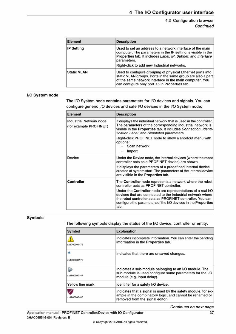
SymbolsThe following symbols display the status of the I/O device, controller or entity.
ExplanationSymbol
Indicates incomplete information. You can enter the pendinginformation in the Properties tab.
xx1700001175
Indicates that there are unsaved changes.xx1700001176
Indicates a sub-module belonging to an I/O module. Thesub-module is used configure some parameters for the I/Omodule (e.g. input delay).xx1800000147
Identifier for a safety I/O device.Yellow line mark
Indicates that a signal is used by the safety module, for ex-ample in the combinatory logic, and cannot be renamed orremoved from the signal editor.xx1800000406
Continues on next pageApplication manual - PROFINET Controller/Device with IO Configurator 373HAC065546-001 Revision: B
© Copyright 2018 ABB. All rights reserved.
4 The I/O Configurator user interface4.3 Configuration browser
Continued
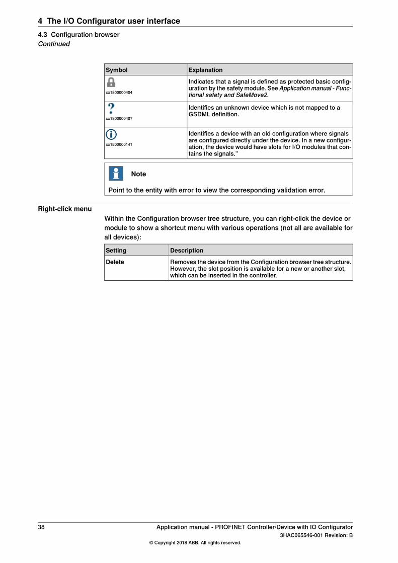
ExplanationSymbol
Indicates that a signal is defined as protected basic config-uration by the safety module. SeeApplicationmanual - Func-tional safety and SafeMove2.xx1800000404
Identifies an unknown device which is not mapped to aGSDML definition.
xx1800000407
Identifies a device with an old configuration where signalsare configured directly under the device. In a new configur-ation, the device would have slots for I/O modules that con-tains the signals.”
xx1800000141
Note
Point to the entity with error to view the corresponding validation error.
Right-click menuWithin the Configuration browser tree structure, you can right-click the device ormodule to show a shortcut menu with various operations (not all are available forall devices):
DescriptionSetting
Removes the device from the Configuration browser tree structure.However, the slot position is available for a new or another slot,which can be inserted in the controller.
Delete
38 Application manual - PROFINET Controller/Device with IO Configurator3HAC065546-001 Revision: B
© Copyright 2018 ABB. All rights reserved.
4 The I/O Configurator user interface4.3 Configuration browserContinued
4.4 Properties browser
Properties tabThe Properties tab displays the parameters of the Communication node and I/OSystem node. You can configure the parameters visible in the Properties tab. Formore information about Communication parameters, see section Communicationin the Technical reference manual - System parameters.
Device Catalogue tabThe Device Catalogue tab displays the predefined device templates or cataloguesused to configure the I/O device. For PROFINET devices, GSDML files are importedto configure the I/O devices. The installed device templates are visible in theDeviceCatalogue tab.
Application manual - PROFINET Controller/Device with IO Configurator 393HAC065546-001 Revision: B
© Copyright 2018 ABB. All rights reserved.
4 The I/O Configurator user interface4.4 Properties browser

4.5 Signal Editor
OverviewThe Signal Editor tab displays the signals assigned to the I/O device. It is used toview the signals and to add new signals to the I/O device. For more informationabout attributes of signal, refer to Technical referencemanual - System parameters.
40 Application manual - PROFINET Controller/Device with IO Configurator3HAC065546-001 Revision: B
© Copyright 2018 ABB. All rights reserved.
4 The I/O Configurator user interface4.5 Signal Editor
4.6 Scan Editor
OverviewThe Scan Editor tab displays the I/O devices discovered in the controller networkscan. It displays information such as MAC, Station Name, IP, Subnet, Gateway,Vendor Id, and Device Id.When scan network is run, Scan Editor displays all the I/O devices in the network.You can then configure the I/O devices that are found but not already configuredin the controller. For example, in the Communication node, if LAN3 is configuredas the network interface and the scan network is run. Then the LAN3 interface isused as the scan interface and devices are identified with the device details. Formore information, see to Scan the network on page 46.
Note
PROFINET station name follows the PROFINET naming convention. It uses lowercase alphabets for naming station name.
Right-click menuWithin the Scan Editor, you can right-click the device row to show a menu ofoptions:
DescriptionSetting
Selects a device and add it to the configuration tree.Add as
Blink with the device status LEDs in order to identify it.Blink
Resets the IP settings of the device to factory reset.Factory Reset
The following buttons are available in the Scan Editor:
DescriptionSetting
Lists all the devices that are reachable on this network.Refresh
Exports a .csv file with all devices and the columns with data foreach device.
Export
To change a device's parameters, double-click on that device andenter the values that needs to be changed.
Send Changes
Clicking Send Changes will save these changes.
Application manual - PROFINET Controller/Device with IO Configurator 413HAC065546-001 Revision: B
© Copyright 2018 ABB. All rights reserved.
4 The I/O Configurator user interface4.6 Scan Editor

This page is intentionally left blank
5 Configuring internal controller and external deviceusing IO Configurator5.1 Configuring with IO Configurator
Log in as safety userIf working with safe I/O signals, log in as a safety user (the user grant SafetyServices is required). See Operating manual - RobotStudio, section Managing theuser authorization system.
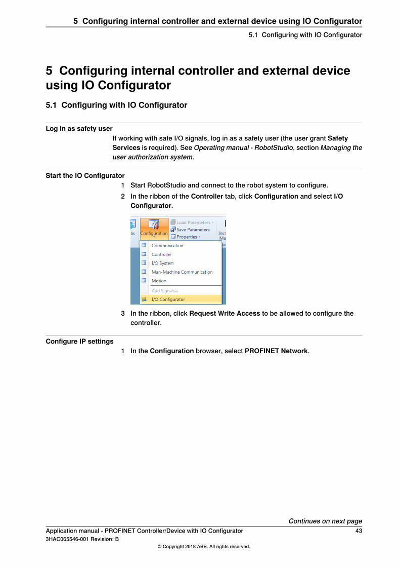
Start the IO Configurator1 Start RobotStudio and connect to the robot system to configure.2 In the ribbon of the Controller tab, click Configuration and select I/O
Configurator.
3 In the ribbon, click Request Write Access to be allowed to configure thecontroller.
Configure IP settings1 In the Configuration browser, select PROFINET Network.
Continues on next pageApplication manual - PROFINET Controller/Device with IO Configurator 433HAC065546-001 Revision: B
© Copyright 2018 ABB. All rights reserved.
5 Configuring internal controller and external device using IO Configurator5.1 Configuring with IO Configurator
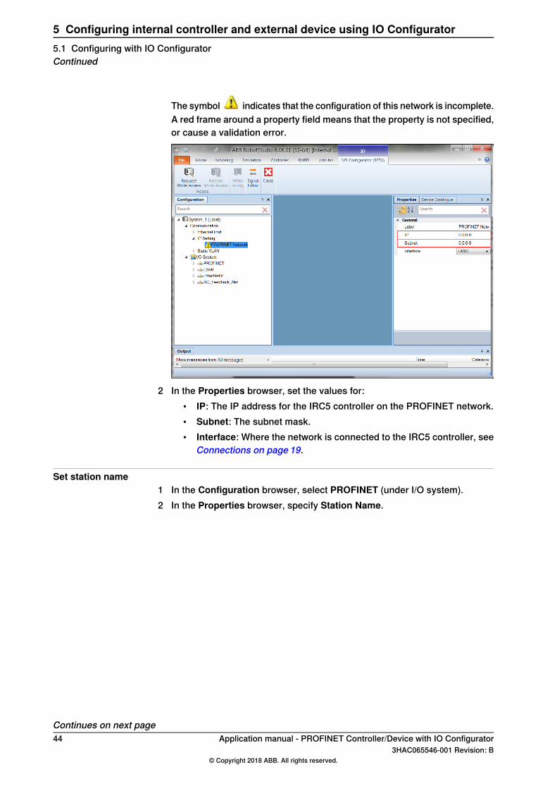
The symbol indicates that the configuration of this network is incomplete.A red frame around a property field means that the property is not specified,or cause a validation error.
2 In the Properties browser, set the values for:• IP: The IP address for the IRC5 controller on the PROFINET network.• Subnet: The subnet mask.• Interface: Where the network is connected to the IRC5 controller, see
Connections on page 19.
Set station name1 In the Configuration browser, select PROFINET (under I/O system).2 In the Properties browser, specify Station Name.
Continues on next page44 Application manual - PROFINET Controller/Device with IO Configurator
3HAC065546-001 Revision: B© Copyright 2018 ABB. All rights reserved.
5 Configuring internal controller and external device using IO Configurator5.1 Configuring with IO ConfiguratorContinued
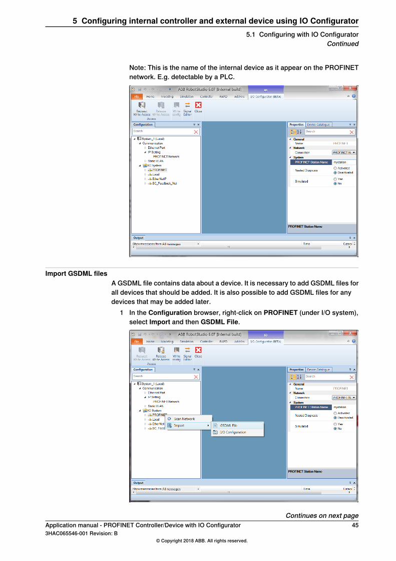
Note: This is the name of the internal device as it appear on the PROFINETnetwork. E.g. detectable by a PLC.
Import GSDML filesA GSDML file contains data about a device. It is necessary to add GSDML files forall devices that should be added. It is also possible to add GSDML files for anydevices that may be added later.
1 In the Configuration browser, right-click on PROFINET (under I/O system),select Import and then GSDML File.
Continues on next pageApplication manual - PROFINET Controller/Device with IO Configurator 453HAC065546-001 Revision: B
© Copyright 2018 ABB. All rights reserved.
5 Configuring internal controller and external device using IO Configurator5.1 Configuring with IO Configurator
Continued
2 Select the GSDML file for the I/O device to add to the network.
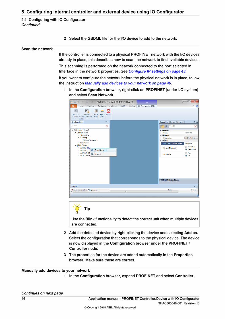
Scan the networkIf the controller is connected to a physical PROFINET network with the I/O devicesalready in place, this describes how to scan the network to find available devices.This scanning is performed on the network connected to the port selected inInterface in the network properties. See Configure IP settings on page 43.If you want to configure the network before the physical network is in place, followthe instruction Manually add devices to your network on page 46.
1 In the Configuration browser, right-click on PROFINET (under I/O system)and select Scan Network.
Tip
Use the Blink functionality to detect the correct unit when multiple devicesare connected.
2 Add the detected device by right-clicking the device and selecting Add as.Select the configuration that corresponds to the physical device. The deviceis now displayed in the Configuration browser under the PROFINET /Controller node.
3 The properties for the device are added automatically in the Propertiesbrowser. Make sure these are correct.
Manually add devices to your network1 In the Configuration browser, expand PROFINET and select Controller.
Continues on next page46 Application manual - PROFINET Controller/Device with IO Configurator
3HAC065546-001 Revision: B© Copyright 2018 ABB. All rights reserved.
5 Configuring internal controller and external device using IO Configurator5.1 Configuring with IO ConfiguratorContinued
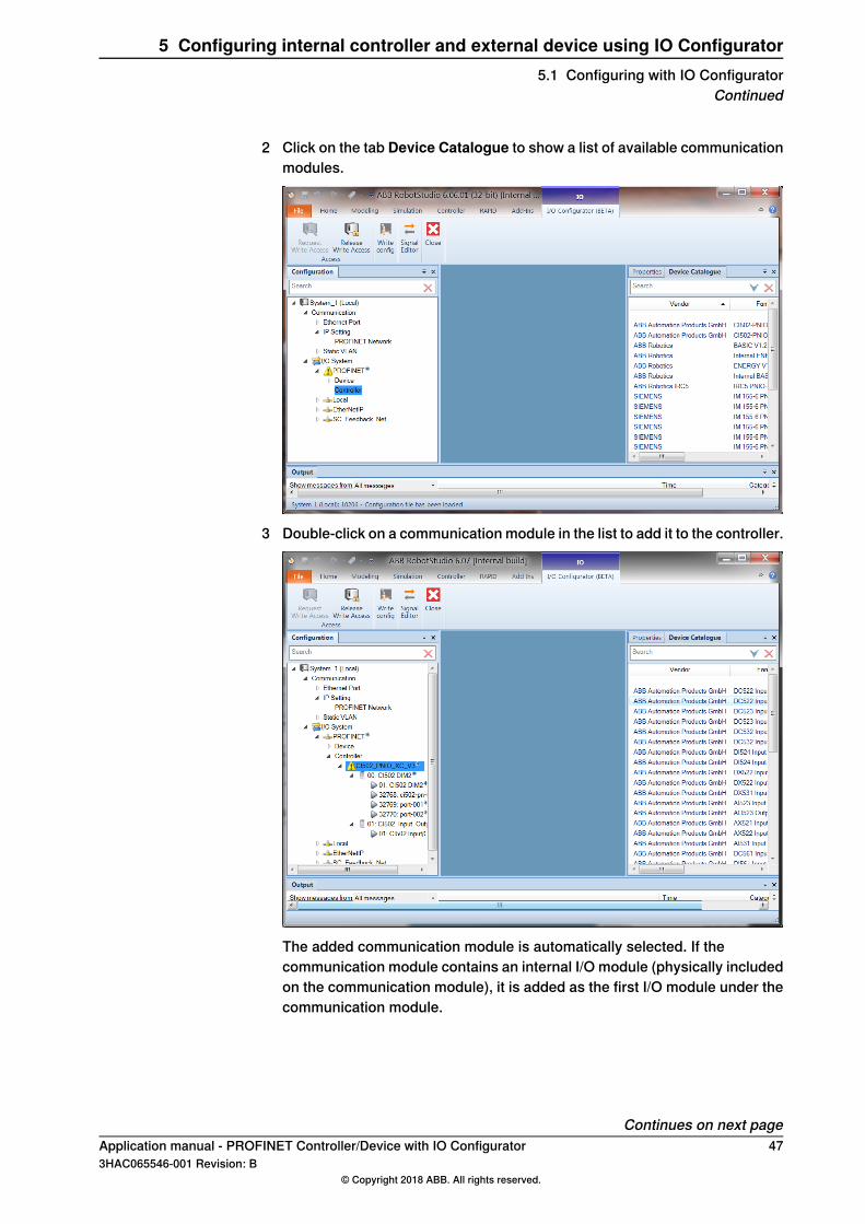
2 Click on the tab Device Catalogue to show a list of available communicationmodules.
3 Double-click on a communication module in the list to add it to the controller.
The added communication module is automatically selected. If thecommunication module contains an internal I/O module (physically includedon the communication module), it is added as the first I/O module under thecommunication module.
Continues on next pageApplication manual - PROFINET Controller/Device with IO Configurator 473HAC065546-001 Revision: B
© Copyright 2018 ABB. All rights reserved.
5 Configuring internal controller and external device using IO Configurator5.1 Configuring with IO Configurator
Continued
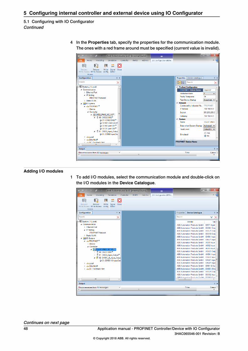
4 In the Properties tab, specify the properties for the communication module.The ones with a red frame around must be specified (current value is invalid).
Adding I/O modules1 To add I/O modules, select the communication module and double-click on
the I/O modules in the Device Catalogue.
Continues on next page48 Application manual - PROFINET Controller/Device with IO Configurator
3HAC065546-001 Revision: B© Copyright 2018 ABB. All rights reserved.
5 Configuring internal controller and external device using IO Configurator5.1 Configuring with IO ConfiguratorContinued
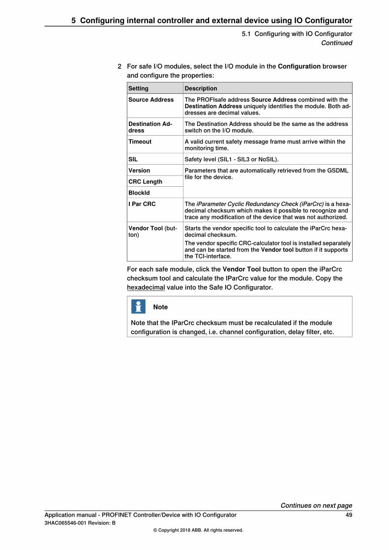
2 For safe I/O modules, select the I/O module in the Configuration browserand configure the properties:
DescriptionSetting
The PROFIsafe address Source Address combined with theDestination Address uniquely identifies the module. Both ad-dresses are decimal values.
Source Address
The Destination Address should be the same as the addressswitch on the I/O module.
Destination Ad-dress
A valid current safety message frame must arrive within themonitoring time.
Timeout
Safety level (SIL1 - SIL3 or NoSIL).SIL
Parameters that are automatically retrieved from the GSDMLfile for the device.
Version
CRC Length
BlockId
The iParameter Cyclic Redundancy Check (iParCrc) is a hexa-decimal checksum which makes it possible to recognize andtrace any modification of the device that was not authorized.
I Par CRC
Starts the vendor specific tool to calculate the iParCrc hexa-decimal checksum.
Vendor Tool (but-ton)
The vendor specific CRC-calculator tool is installed separatelyand can be started from the Vendor tool button if it supportsthe TCI-interface.
For each safe module, click the Vendor Tool button to open the iParCrcchecksum tool and calculate the IParCrc value for the module. Copy thehexadecimal value into the Safe IO Configurator.
Note
Note that the IParCrc checksum must be recalculated if the moduleconfiguration is changed, i.e. channel configuration, delay filter, etc.
Continues on next pageApplication manual - PROFINET Controller/Device with IO Configurator 493HAC065546-001 Revision: B
© Copyright 2018 ABB. All rights reserved.
5 Configuring internal controller and external device using IO Configurator5.1 Configuring with IO Configurator
Continued
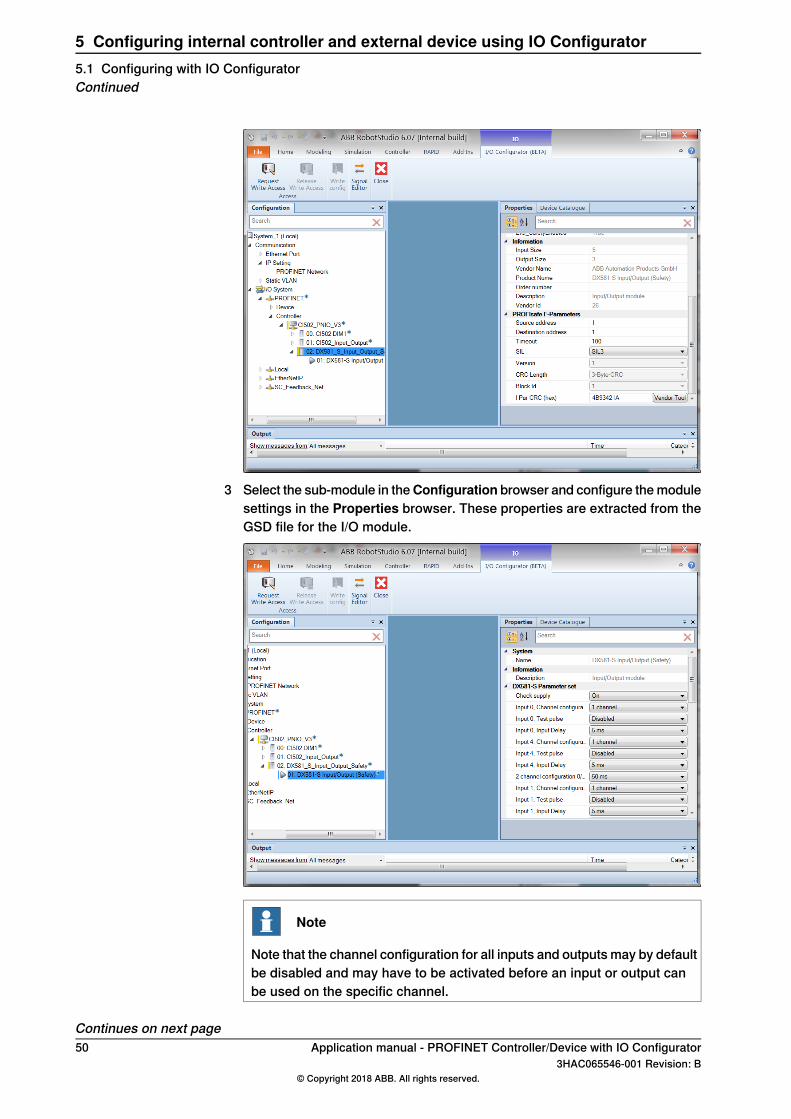
3 Select the sub-module in theConfiguration browser and configure the modulesettings in the Properties browser. These properties are extracted from theGSD file for the I/O module.
Note
Note that the channel configuration for all inputs and outputs may by defaultbe disabled and may have to be activated before an input or output canbe used on the specific channel.
Continues on next page50 Application manual - PROFINET Controller/Device with IO Configurator
3HAC065546-001 Revision: B© Copyright 2018 ABB. All rights reserved.
5 Configuring internal controller and external device using IO Configurator5.1 Configuring with IO ConfiguratorContinued
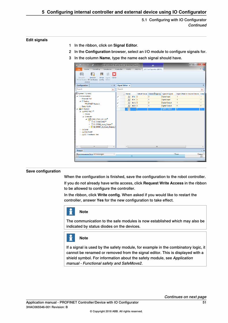
Edit signals1 In the ribbon, click on Signal Editor.2 In the Configuration browser, select an I/O module to configure signals for.3 In the column Name, type the name each signal should have.
Save configurationWhen the configuration is finished, save the configuration to the robot controller.If you do not already have write access, click Request Write Access in the ribbonto be allowed to configure the controller.In the ribbon, click Write config. When asked if you would like to restart thecontroller, answer Yes for the new configuration to take effect.
Note
The communication to the safe modules is now established which may also beindicated by status diodes on the devices.
Note
If a signal is used by the safety module, for example in the combinatory logic, itcannot be renamed or removed from the signal editor. This is displayed with ashield symbol. For information about the safety module, see Applicationmanual - Functional safety and SafeMove2.
Continues on next pageApplication manual - PROFINET Controller/Device with IO Configurator 513HAC065546-001 Revision: B
© Copyright 2018 ABB. All rights reserved.
5 Configuring internal controller and external device using IO Configurator5.1 Configuring with IO Configurator
Continued
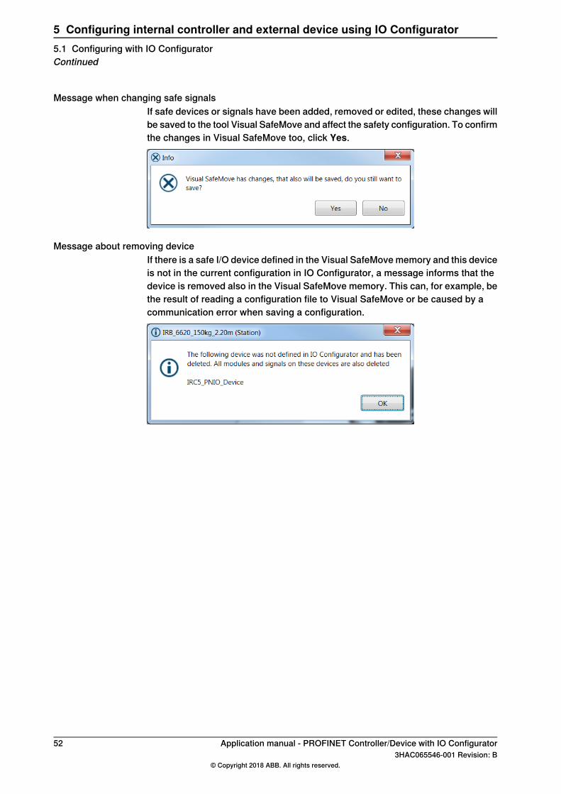
Message when changing safe signalsIf safe devices or signals have been added, removed or edited, these changes willbe saved to the tool Visual SafeMove and affect the safety configuration. To confirmthe changes in Visual SafeMove too, click Yes.
Message about removing deviceIf there is a safe I/O device defined in the Visual SafeMove memory and this deviceis not in the current configuration in IO Configurator, a message informs that thedevice is removed also in the Visual SafeMove memory. This can, for example, bethe result of reading a configuration file to Visual SafeMove or be caused by acommunication error when saving a configuration.
52 Application manual - PROFINET Controller/Device with IO Configurator3HAC065546-001 Revision: B
© Copyright 2018 ABB. All rights reserved.
5 Configuring internal controller and external device using IO Configurator5.1 Configuring with IO ConfiguratorContinued
5.2 Using Fast Device Startup
About Fast Device StartupThe Fast Device Startup functionality is used in tool changing applications toshorten the connection time between the PROFINET controller and an I/O device.To be able to use this functionality, the I/O device needs to support this functionality.All devices must support fast startup in the communication chain. Devices suchas switches or other intermediate hardware that could affect the PROFINETcommunication. For more information, see Poor performance using fast startupon page 84.Some manufacturers also call this functionality Fast Start Up (FSU) or PrioritizedStartup.To activate Fast Device Startup against an I/O device, activate the system parameterFast Device Startup and select the corresponding port(s) to be configured. SeeFast Device Startup on page 70.
Note
The I/O device with FSU functionality is connected with the IRC5 controller. Whenthe power of the I/O device is switched off and switched on again, the IRC5controller establishes contact with the I/O device using the fast startup sequence.
Three alternative connections
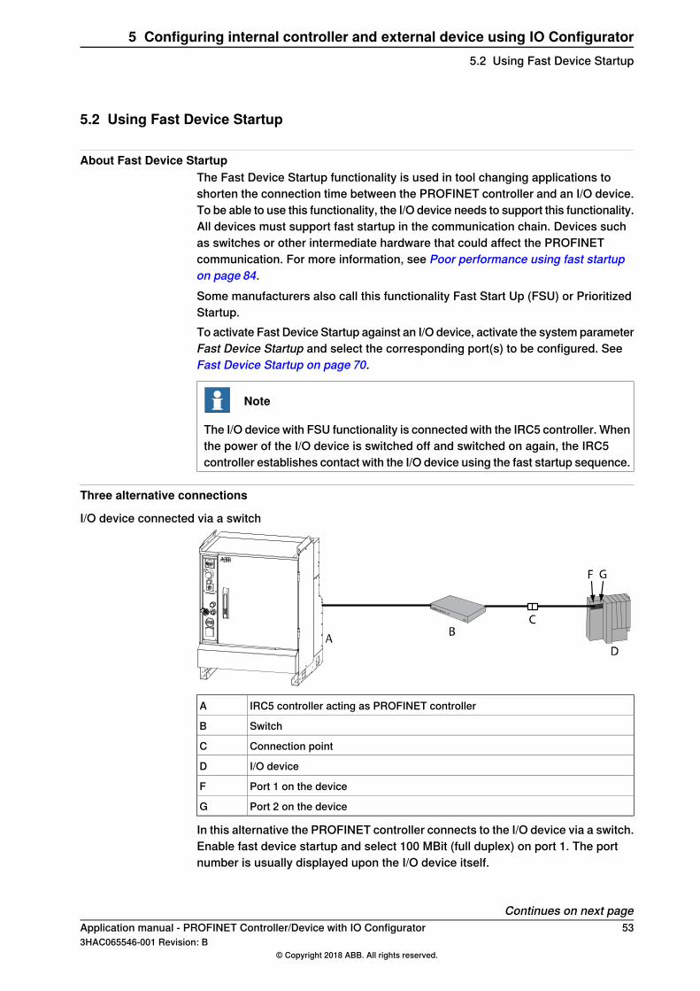
I/O device connected via a switch
IRC5 controller acting as PROFINET controllerA
SwitchB
Connection pointC
I/O deviceD
Port 1 on the deviceF
Port 2 on the deviceG
In this alternative the PROFINET controller connects to the I/O device via a switch.Enable fast device startup and select 100 MBit (full duplex) on port 1. The portnumber is usually displayed upon the I/O device itself.
Continues on next pageApplication manual - PROFINET Controller/Device with IO Configurator 533HAC065546-001 Revision: B
© Copyright 2018 ABB. All rights reserved.
5 Configuring internal controller and external device using IO Configurator5.2 Using Fast Device Startup
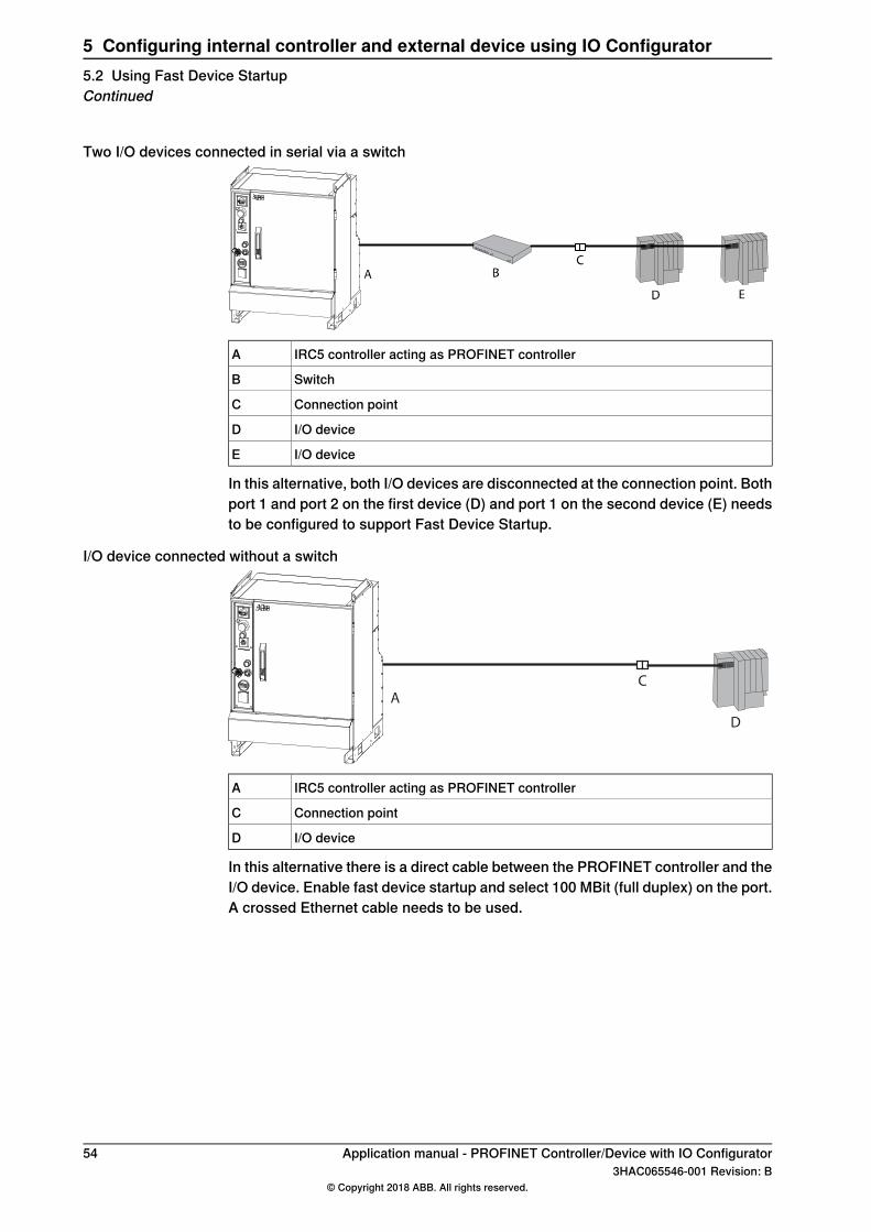
Two I/O devices connected in serial via a switch
IRC5 controller acting as PROFINET controllerA
SwitchB
Connection pointC
I/O deviceD
I/O deviceE
In this alternative, both I/O devices are disconnected at the connection point. Bothport 1 and port 2 on the first device (D) and port 1 on the second device (E) needsto be configured to support Fast Device Startup.
I/O device connected without a switch
A
C
D
IRC5 controller acting as PROFINET controllerA
Connection pointC
I/O deviceD
In this alternative there is a direct cable between the PROFINET controller and theI/O device. Enable fast device startup and select 100 MBit (full duplex) on the port.A crossed Ethernet cable needs to be used.
54 Application manual - PROFINET Controller/Device with IO Configurator3HAC065546-001 Revision: B
© Copyright 2018 ABB. All rights reserved.
5 Configuring internal controller and external device using IO Configurator5.2 Using Fast Device StartupContinued

6 Configuring the internal device using IO Configurator(for option 997-2)Log in as safety user
If working with safe I/O signals, log in as a safety user (the user grant SafetyServices is required). See Operating manual - RobotStudio, section Managing theuser authorization system.
Start the IO Configurator1 Start RobotStudio and connect to the robot system to configure.2 In the ribbon of the Controller tab, click Configuration and select I/O
Configurator.
3 In the ribbon, click Request Write Access to be allowed to configure thecontroller.
Continues on next pageApplication manual - PROFINET Controller/Device with IO Configurator 553HAC065546-001 Revision: B
© Copyright 2018 ABB. All rights reserved.
6 Configuring the internal device using IO Configurator (for option 997-2)
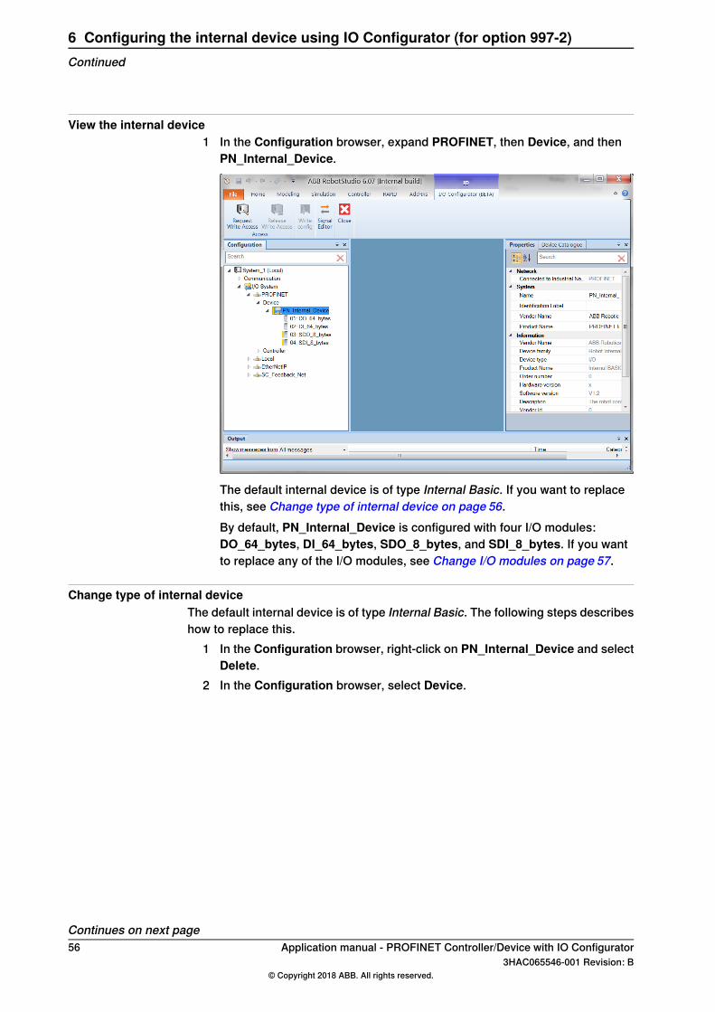
View the internal device1 In the Configuration browser, expand PROFINET, then Device, and then
PN_Internal_Device.
The default internal device is of type Internal Basic. If you want to replacethis, see Change type of internal device on page 56.By default, PN_Internal_Device is configured with four I/O modules:DO_64_bytes, DI_64_bytes, SDO_8_bytes, and SDI_8_bytes. If you wantto replace any of the I/O modules, see Change I/O modules on page 57.
Change type of internal deviceThe default internal device is of type Internal Basic. The following steps describeshow to replace this.
1 In the Configuration browser, right-click on PN_Internal_Device and selectDelete.
2 In the Configuration browser, select Device.
Continues on next page56 Application manual - PROFINET Controller/Device with IO Configurator
3HAC065546-001 Revision: B© Copyright 2018 ABB. All rights reserved.
6 Configuring the internal device using IO Configurator (for option 997-2)Continued
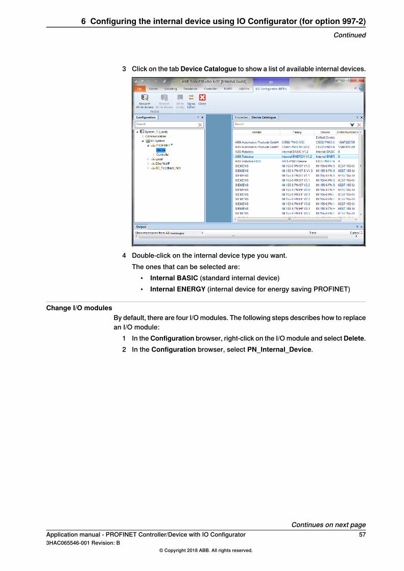
3 Click on the tabDevice Catalogue to show a list of available internal devices.
4 Double-click on the internal device type you want.The ones that can be selected are:
• Internal BASIC (standard internal device)• Internal ENERGY (internal device for energy saving PROFINET)
Change I/O modulesBy default, there are four I/O modules. The following steps describes how to replacean I/O module:
1 In theConfiguration browser, right-click on the I/O module and selectDelete.2 In the Configuration browser, select PN_Internal_Device.
Continues on next pageApplication manual - PROFINET Controller/Device with IO Configurator 573HAC065546-001 Revision: B
© Copyright 2018 ABB. All rights reserved.
6 Configuring the internal device using IO Configurator (for option 997-2)Continued
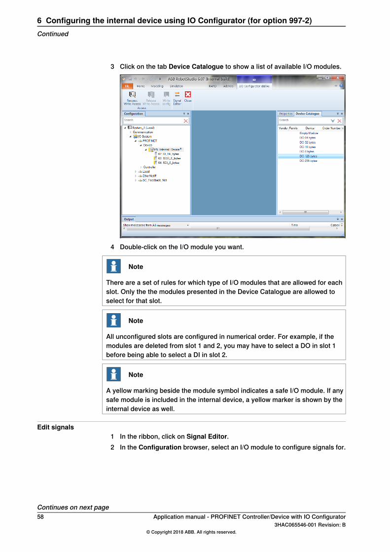
3 Click on the tab Device Catalogue to show a list of available I/O modules.
4 Double-click on the I/O module you want.
Note
There are a set of rules for which type of I/O modules that are allowed for eachslot. Only the the modules presented in the Device Catalogue are allowed toselect for that slot.
Note
All unconfigured slots are configured in numerical order. For example, if themodules are deleted from slot 1 and 2, you may have to select a DO in slot 1before being able to select a DI in slot 2.
Note
A yellow marking beside the module symbol indicates a safe I/O module. If anysafe module is included in the internal device, a yellow marker is shown by theinternal device as well.
Edit signals1 In the ribbon, click on Signal Editor.2 In the Configuration browser, select an I/O module to configure signals for.
Continues on next page58 Application manual - PROFINET Controller/Device with IO Configurator
3HAC065546-001 Revision: B© Copyright 2018 ABB. All rights reserved.
6 Configuring the internal device using IO Configurator (for option 997-2)Continued
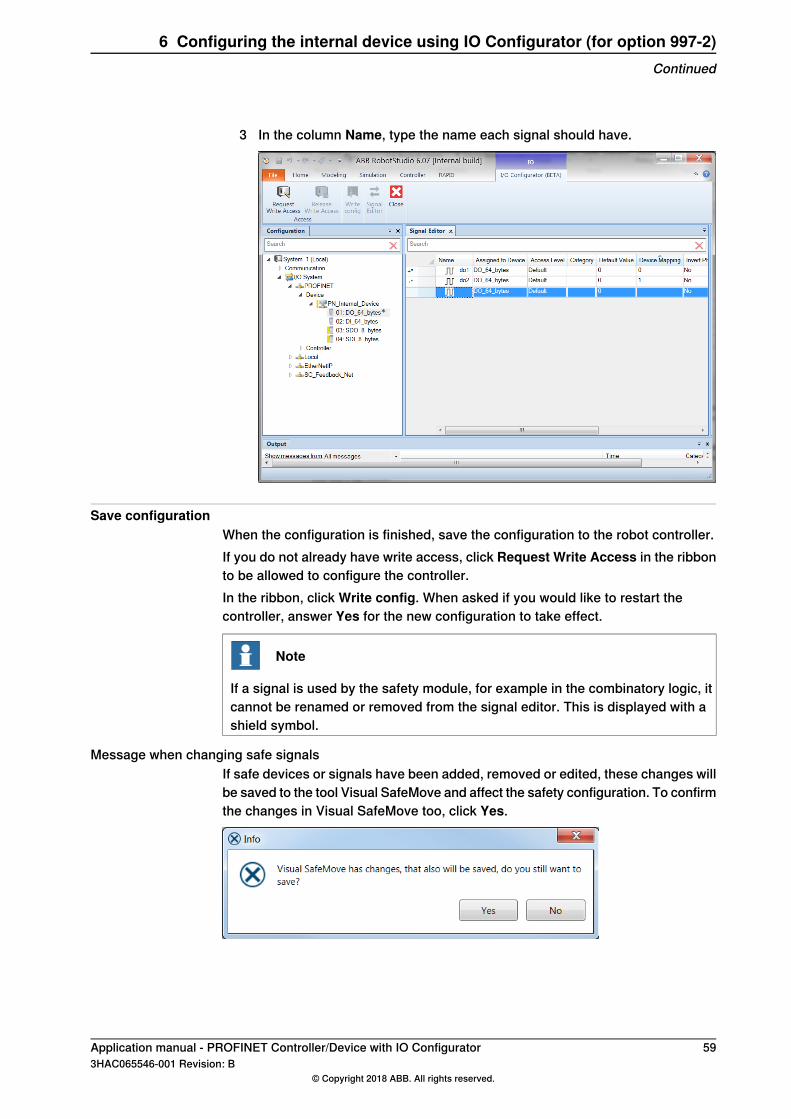
3 In the column Name, type the name each signal should have.
Save configurationWhen the configuration is finished, save the configuration to the robot controller.If you do not already have write access, click Request Write Access in the ribbonto be allowed to configure the controller.In the ribbon, click Write config. When asked if you would like to restart thecontroller, answer Yes for the new configuration to take effect.
Note
If a signal is used by the safety module, for example in the combinatory logic, itcannot be renamed or removed from the signal editor. This is displayed with ashield symbol.
Message when changing safe signalsIf safe devices or signals have been added, removed or edited, these changes willbe saved to the tool Visual SafeMove and affect the safety configuration. To confirmthe changes in Visual SafeMove too, click Yes.
Application manual - PROFINET Controller/Device with IO Configurator 593HAC065546-001 Revision: B
© Copyright 2018 ABB. All rights reserved.
6 Configuring the internal device using IO Configurator (for option 997-2)Continued

This page is intentionally left blank
7 Configuring the internal device using IO Configurator(for option 997-1)Log in as safety user
If working with safe I/O signals, log in as a safety user (the user grant SafetyServices is required). See Operating manual - RobotStudio, section Managing theuser authorization system.
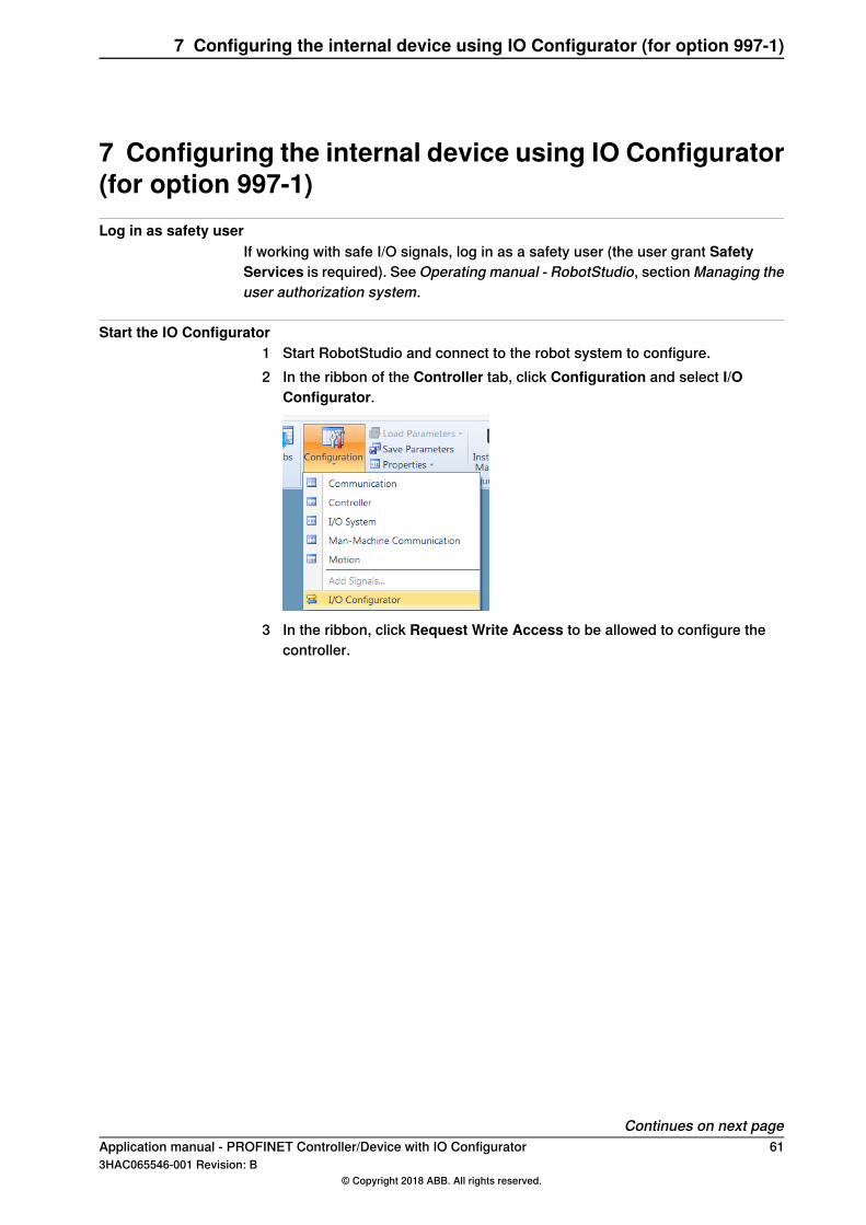
Start the IO Configurator1 Start RobotStudio and connect to the robot system to configure.2 In the ribbon of the Controller tab, click Configuration and select I/O
Configurator.
3 In the ribbon, click Request Write Access to be allowed to configure thecontroller.
Continues on next pageApplication manual - PROFINET Controller/Device with IO Configurator 613HAC065546-001 Revision: B
© Copyright 2018 ABB. All rights reserved.
7 Configuring the internal device using IO Configurator (for option 997-1)
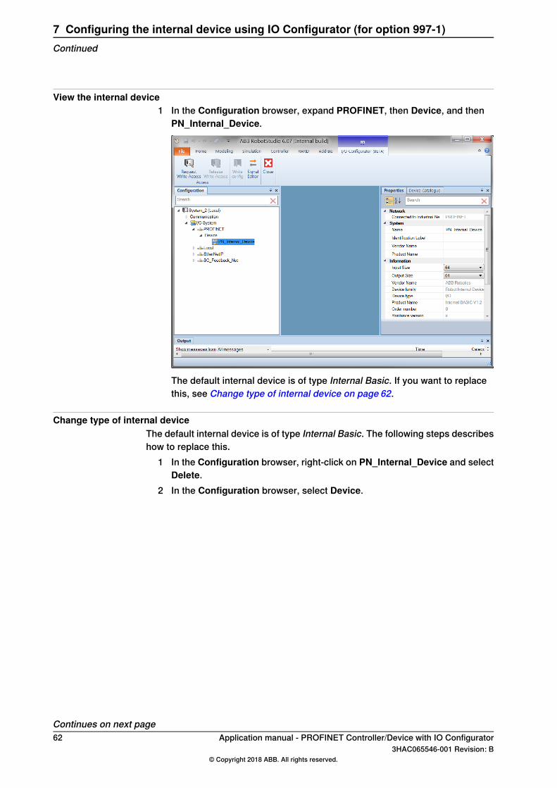
View the internal device1 In the Configuration browser, expand PROFINET, then Device, and then
PN_Internal_Device.
The default internal device is of type Internal Basic. If you want to replacethis, see Change type of internal device on page 62.
Change type of internal deviceThe default internal device is of type Internal Basic. The following steps describeshow to replace this.
1 In the Configuration browser, right-click on PN_Internal_Device and selectDelete.
2 In the Configuration browser, select Device.
Continues on next page62 Application manual - PROFINET Controller/Device with IO Configurator
3HAC065546-001 Revision: B© Copyright 2018 ABB. All rights reserved.
7 Configuring the internal device using IO Configurator (for option 997-1)Continued
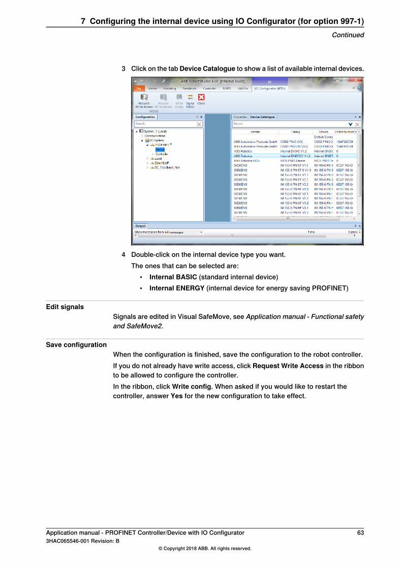
3 Click on the tabDevice Catalogue to show a list of available internal devices.
4 Double-click on the internal device type you want.The ones that can be selected are:
• Internal BASIC (standard internal device)• Internal ENERGY (internal device for energy saving PROFINET)
Edit signalsSignals are edited in Visual SafeMove, see Application manual - Functional safetyand SafeMove2.
Save configurationWhen the configuration is finished, save the configuration to the robot controller.If you do not already have write access, click Request Write Access in the ribbonto be allowed to configure the controller.In the ribbon, click Write config. When asked if you would like to restart thecontroller, answer Yes for the new configuration to take effect.
Application manual - PROFINET Controller/Device with IO Configurator 633HAC065546-001 Revision: B
© Copyright 2018 ABB. All rights reserved.
7 Configuring the internal device using IO Configurator (for option 997-1)Continued

This page is intentionally left blank
8 System parameters8.1 Introduction
About the system parametersThere are both PROFINET specific parameters and more general parameters. Thischapter describes all PROFINET specific system parameters. The parameters aredivided into the type they belong to. For information about other parameters, seeTechnical reference manual - System parameters.
PROFINET system parameters
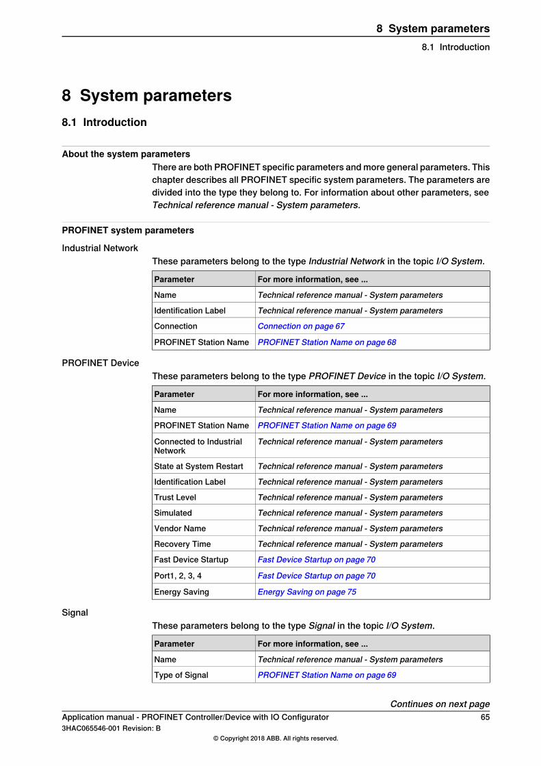
Industrial NetworkThese parameters belong to the type Industrial Network in the topic I/O System.
For more information, see ...Parameter
Technical reference manual - System parametersName
Technical reference manual - System parametersIdentification Label
Connection on page 67Connection
PROFINET Station Name on page 68PROFINET Station Name
PROFINET DeviceThese parameters belong to the type PROFINET Device in the topic I/O System.
For more information, see ...Parameter
Technical reference manual - System parametersName
PROFINET Station Name on page 69PROFINET Station Name
Technical reference manual - System parametersConnected to IndustrialNetwork
Technical reference manual - System parametersState at System Restart
Technical reference manual - System parametersIdentification Label
Technical reference manual - System parametersTrust Level
Technical reference manual - System parametersSimulated
Technical reference manual - System parametersVendor Name
Technical reference manual - System parametersRecovery Time
Fast Device Startup on page 70Fast Device Startup
Fast Device Startup on page 70Port1, 2, 3, 4
Energy Saving on page 75Energy Saving
SignalThese parameters belong to the type Signal in the topic I/O System.
For more information, see ...Parameter
Technical reference manual - System parametersName
PROFINET Station Name on page 69Type of Signal
Continues on next pageApplication manual - PROFINET Controller/Device with IO Configurator 653HAC065546-001 Revision: B
© Copyright 2018 ABB. All rights reserved.
8 System parameters8.1 Introduction
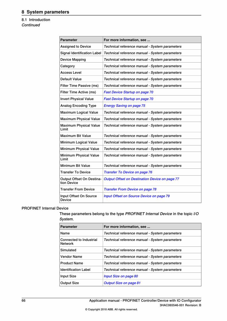
For more information, see ...Parameter
Technical reference manual - System parametersAssigned to Device
Technical reference manual - System parametersSignal Identification Label
Technical reference manual - System parametersDevice Mapping
Technical reference manual - System parametersCategory
Technical reference manual - System parametersAccess Level
Technical reference manual - System parametersDefault Value
Technical reference manual - System parametersFilter Time Passive (ms)
Fast Device Startup on page 70Filter Time Active (ms)
Fast Device Startup on page 70Invert Physical Value
Energy Saving on page 75Analog Encoding Type
Technical reference manual - System parametersMaximum Logical Value
Technical reference manual - System parametersMaximum Physical Value
Technical reference manual - System parametersMaximum Physical ValueLimit
Technical reference manual - System parametersMaximum Bit Value
Technical reference manual - System parametersMinimum Logical Value
Technical reference manual - System parametersMinimum Physical Value
Technical reference manual - System parametersMinimum Physical ValueLimit
Technical reference manual - System parametersMinimum Bit Value
Transfer To Device on page 76Transfer To Device
Output Offset on Destination Device on page 77Output Offset On Destina-tion Device
Transfer From Device on page 78Transfer From Device
Input Offset on Source Device on page 79Input Offset On SourceDevice
PROFINET Internal DeviceThese parameters belong to the type PROFINET Internal Device in the topic I/OSystem.
For more information, see ...Parameter
Technical reference manual - System parametersName
Technical reference manual - System parametersConnected to IndustrialNetwork
Technical reference manual - System parametersSimulated
Technical reference manual - System parametersVendor Name
Technical reference manual - System parametersProduct Name
Technical reference manual - System parametersIdentification Label
Input Size on page 80Input Size
Output Size on page 81Output Size
66 Application manual - PROFINET Controller/Device with IO Configurator3HAC065546-001 Revision: B
© Copyright 2018 ABB. All rights reserved.
8 System parameters8.1 IntroductionContinued
8.2 Type Industrial Network
8.2.1 Connection
ParentConnection belongs to the type Industrial Network, in the topic I/O System.
Cfg nameConnection
DescriptionThe parameter Connection specifies the IP Setting that the PROFINET industrialnetwork shall use.
Default valuePROFINET Network
Allowed valuesValid instances of IP Setting
Additional informationThe Public Network or the Private Network cannot be edited by external controllersor tool, such as NetNames+.
Application manual - PROFINET Controller/Device with IO Configurator 673HAC065546-001 Revision: B
© Copyright 2018 ABB. All rights reserved.
8 System parameters8.2.1 Connection
8.2.2 PROFINET Station Name
ParentPROFINET Station Name belongs to the type Industrial Network, in the topic I/OSystem.
Cfg nameStationName
DescriptionPROFINET Station Name specifies the PROFINET station name on the network ofthe IRC5 controller.
UsageThe parameter PROFINET Station Name is used to identify a PROFINET deviceon the network. The name must be unique on the network.The parameter PROFINET Station Name can also be changed with an externalPROFINET configuration tool or a connecting PROFINET controller.
PrerequisitesThe option PROFINET Controller/Device or PROFINET Device must be installed.
Default valueThe default value is an empty string.
Allowed valuesA string with maximum 80 characters.Allowed characters:
• 0-9 (numerical)• a-z (lowercase letters)• - (hyphen)• . (full stop)
68 Application manual - PROFINET Controller/Device with IO Configurator3HAC065546-001 Revision: B
© Copyright 2018 ABB. All rights reserved.
8 System parameters8.2.2 PROFINET Station Name
8.3 Type PROFINET Device
8.3.1 PROFINET Station Name
ParentPROFINET Station Name belongs to the type PROFINET Device, in the topic I/OSystem.
Cfg nameStationName
DescriptionPROFINET Station Name specifies the PROFINET station name on the network ofthe external I/O device.
UsageThe parameter PROFINET Station Name is used to identify a PROFINET deviceon the network. The name must be unique on the network.
PrerequisitesThe option PROFINET Controller/Device or PROFINET Device must be installed.
Default valueThe default value is an empty string.
Allowed valuesThe station name follows the PROFINET naming convention for IO devices.
Application manual - PROFINET Controller/Device with IO Configurator 693HAC065546-001 Revision: B
© Copyright 2018 ABB. All rights reserved.
8 System parameters8.3.1 PROFINET Station Name
8.3.2 Fast Device Startup
ParentFast Device Startup belongs to the type PROFINET Device, in the topic I/O System.
Cfg nameFastDeviceStartup
DescriptionThe parameter Fast Device Startup specifies if the I/O device should use a fasterconnection attempt algorithm or not.
UsageThe parameter Fast Device Startup is used mainly to speed up tool changeapplications. The usual PROFINET connection attempt takes a few seconds tocomplete, but with Fast Device Startup enabled devices, this time is shortened toless than a second. For more information, see Using Fast Device Startup onpage 53.
PrerequisitesThe option PROFINET Controller/Device must be installed.
LimitationsThe Ethernet switches between the IRC5 controller and the I/O device that usesthe Fast Device Startup functionality. It must be configured to disable the autocrossover and automatic speed detection functions on used connectors. The speedrate is set to 100Mbps (full duplex).
Default valueThe default value is Deactivated.
Allowed values• Deactivated• Activated• Support
Note
Select Support to set the desired port speed. For port speed, select 100 Mbpsand the port speed is adjusted to 100Mbps, and auto negotiation is turned offfor the port.Hence, it is possible to change the settings on a built-in switch for a PROFINETI/O device.
70 Application manual - PROFINET Controller/Device with IO Configurator3HAC065546-001 Revision: B
© Copyright 2018 ABB. All rights reserved.
8 System parameters8.3.2 Fast Device Startup
8.3.3 Port 1
ParentPort 1 belongs to the type PROFINET Device, in the topic I/O System.
Cfg nameFastDeviceStartup_Port1
DescriptionThe parameter Port 1 specifies fast device startup port 1 in the I/O device.
UsageThe parameter Fast Device Startup is configured at port 1 of the I/O device.
PrerequisitesThe parameter Fast Device Startup must be activated.
Default valueThe default value is Deactivated.
Allowed values• Deactivated• 100 Mbps
Application manual - PROFINET Controller/Device with IO Configurator 713HAC065546-001 Revision: B
© Copyright 2018 ABB. All rights reserved.
8 System parameters8.3.3 Port 1

8.3.4 Port 2
ParentPort 2 belongs to the type PROFINET Device, in the topic I/O System.
Cfg nameFastDeviceStartup_Port2
DescriptionThe parameter Port 2 specifies fast device startup port 2 in the I/O device.
UsageThe parameter Fast Device Startup is configured at port 2 of the I/O device.
PrerequisitesThe parameter Fast Device Startup must be activated.
Default valueThe default value is Deactivated.
Allowed values• Deactivated• 100 Mbps
72 Application manual - PROFINET Controller/Device with IO Configurator3HAC065546-001 Revision: B
© Copyright 2018 ABB. All rights reserved.
8 System parameters8.3.4 Port 2

8.3.5 Port 3
ParentPort 3 belongs to the type PROFINET Device, in the topic I/O System.
Cfg nameFastDeviceStartup_Port3
DescriptionThe parameter Port 3 specifies fast device startup port 3 in the I/O device.
UsageThe parameter Fast Device Startup is configured at port 3 of the I/O device.
PrerequisitesThe parameter Fast Device Startup must be activated.
Default valueThe default value is Deactivated.
Allowed values• Deactivated• 100 Mbps
Application manual - PROFINET Controller/Device with IO Configurator 733HAC065546-001 Revision: B
© Copyright 2018 ABB. All rights reserved.
8 System parameters8.3.5 Port 3
8.3.6 Port 4
ParentPort 4 belongs to the type PROFINET Device, in the topic I/O System.
Cfg nameFastDeviceStartup_Port4
DescriptionThe parameter Port 4 specifies fast device startup port 4 in the I/O device.
UsageThe parameter Fast Device Startup is configured at port 4 of the I/O device.
PrerequisitesThe parameter Fast Device Startup must be activated.
Default valueThe default value is Deactivated.
Allowed values• Deactivated• 100 Mbps
74 Application manual - PROFINET Controller/Device with IO Configurator3HAC065546-001 Revision: B
© Copyright 2018 ABB. All rights reserved.
8 System parameters8.3.6 Port 4
8.3.7 Energy Saving
ParentEnergy Saving belongs to the type PROFINET Device, in the topic I/O System.
Cfg nameEnergy Saving
DescriptionThe parameter Energy Saving specifies if the I/O device should respond to energysaving command or not.
UsageThe parameter Energy Saving is used mainly to activate energy saving mode.
PrerequisitesThe option PROFINET Controller/Device and PROFIenergy must be installed.
Default valueThe default value is Activated.
Allowed values• Activated• Deactivated
Application manual - PROFINET Controller/Device with IO Configurator 753HAC065546-001 Revision: B
© Copyright 2018 ABB. All rights reserved.
8 System parameters8.3.7 Energy Saving
8.4 Type Signal
8.4.1 Transfer To Device
ParentTransfer To Device belongs to the type Signal, in the topic I/O System.
Cfg nameTransferToDevice
DescriptionThe parameter Transfer To Device specifies that the signal shall be transferred tothe internal device starting at the offset specified in the parameter Output OffsetOn Destination Device.
PrerequisitesThe option PROFINET Controller/Device must be installed.
LimitationsOnly signals of type Digital Output/ Digital Input/ Group Output/ Group Input canbe transferred. The destination I/O device can only be the PROFINET internaldevice.
Allowed valuesThe allowed value is the PROFINET internal device.
76 Application manual - PROFINET Controller/Device with IO Configurator3HAC065546-001 Revision: B
© Copyright 2018 ABB. All rights reserved.
8 System parameters8.4.1 Transfer To DevicePROFINET Controller/Device
8.4.2 Output Offset on Destination Device
ParentOutput Offset On Destination Device belongs to the type Signal, in the topic I/OSystem.
Cfg nameTransferOutputOffset
DescriptionThe parameter Output Offset On Destination Device specifies the output start biton the PROFINET internal device set by the transfer signal.
PrerequisitesThe option PROFINET Controller/Device must be installed.
LimitationsThe destination I/O device can only be the PROFINET internal device.
Default valueThe default value is -1. This means that no Output Offset On Destination Deviceis defined.
Allowed valuesThe values are in the range of -1 to 65535.
Additional informationThe parameter Output Offset On Destination Device specifies the start bit on theinternal device. And, for bits specified in a group are transferred starting with thefirst bit.
Application manual - PROFINET Controller/Device with IO Configurator 773HAC065546-001 Revision: B
© Copyright 2018 ABB. All rights reserved.
8 System parameters8.4.2 Output Offset on Destination Device
PROFINET Controller/Device
8.4.3 Transfer From Device
ParentTransfer From Device belongs to the type Signal, in the topic I/O System.
Cfg nameTransferFromDevice
DescriptionThe parameter Transfer From Device specifies that the bit value for the internaldevice (starting at the offset specified in the parameter Input Offset On DestinationDevice) shall be transferred to the signal.
PrerequisitesThe option PROFINET Controller/Device must be installed.
LimitationsOnly the input bits from the PROFINET internal device can be transferred to thesignals of type digital output and group output.
Allowed valuesThe allowed value is the PROFINET internal device.
78 Application manual - PROFINET Controller/Device with IO Configurator3HAC065546-001 Revision: B
© Copyright 2018 ABB. All rights reserved.
8 System parameters8.4.3 Transfer From DevicePROFINET Controller/Device
8.4.4 Input Offset on Source Device
ParentInput Offset on Source Device belongs to the type Signal, in the topic I/O System.
Cfg nameTransferInputOffset
DescriptionThe parameter Input Offset on Source Device specifies the input start bit PROFINETinternal device that will be transferred to the defined signal.
PrerequisitesThe option PROFINET Controller/Device must be installed.
LimitationsThe transfer is possible only to the signals of type digital output and group output.For all cases, it is possible to transfer information from the internal device to signalsdefined on other PROFINET I/O devices only.
Default valueThe default value is -1. This means that Input Offset on Source Device is not defined.
Allowed valuesThe values are in the range of -1 to 65535.
Additional informationThe parameter Input Offset On Destination Device specifies the start bit on theinternal device. The bits specified in a group are transferred starting with the firstbit.
Application manual - PROFINET Controller/Device with IO Configurator 793HAC065546-001 Revision: B
© Copyright 2018 ABB. All rights reserved.
8 System parameters8.4.4 Input Offset on Source Device
PROFINET Controller/Device
8.5 Type PROFINET Internal Device
8.5.1 Input Size
ParentInput Size belongs to the type PROFINET Internal Device, in the topic I/O System.
Cfg nameInputSize
DescriptionThe parameter Input Size is used to configure the input slot configuration of thePROFINET internal device.
UsageIt will configure the input slot size for the PROFINET internal device. This size mustmatch the connecting PLC’s or other PROFINET controller’s defined output slotsize. For more information, see Input and output size on page 30.
PrerequisitesThe option PROFINET Controller/Device or PROFINET Device must be installed.
Default valueThe default value is 64 bytes (512 signal bits).
Allowed values8, 16, 32, 64, 128 or 256 bytes (64, 128, 512, 1024 or 2048 signal bits).
80 Application manual - PROFINET Controller/Device with IO Configurator3HAC065546-001 Revision: B
© Copyright 2018 ABB. All rights reserved.
8 System parameters8.5.1 Input Size
8.5.2 Output Size
ParentOutput Size belongs to the type PROFINET Internal Device, in the topic I/O System.
Cfg nameOutputSize
DescriptionThe parameter Output Size is used to configure the output slot configuration ofthe PROFINET internal device.
UsageThe parameterOutput Size is only valid for the PN_Internal_Device. It will configurethe output slot size for the PROFINET internal device. This size must match theconnecting PLC’s or other PROFINET controller’s defined input slot size. For moreinformation, see Input and output size on page 30.
PrerequisitesThe option PROFINET Controller/Device or PROFINET Device must be installed.
Default valueThe default value is 64 bytes (512 signal bits).
Allowed values8, 16, 32, 64, 128 or 256 bytes (64, 128, 512, 1024 or 2048 signal bits).
Application manual - PROFINET Controller/Device with IO Configurator 813HAC065546-001 Revision: B
© Copyright 2018 ABB. All rights reserved.
8 System parameters8.5.2 Output Size

This page is intentionally left blank
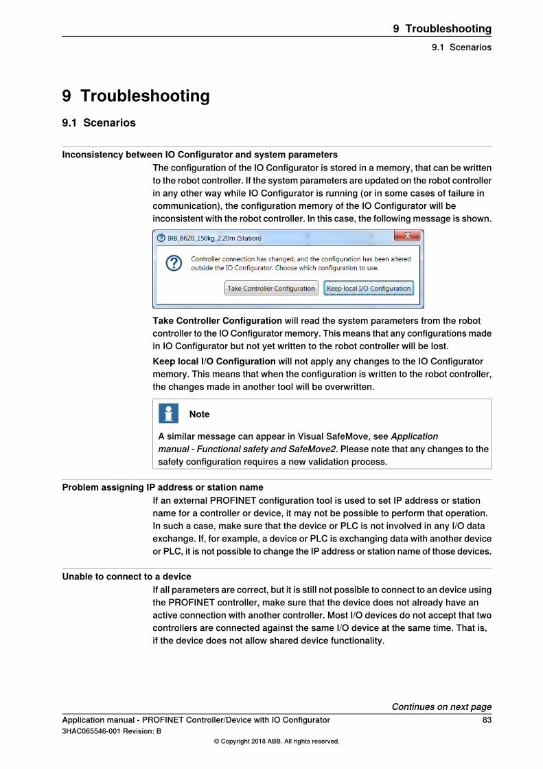
9 Troubleshooting9.1 Scenarios
Inconsistency between IO Configurator and system parametersThe configuration of the IO Configurator is stored in a memory, that can be writtento the robot controller. If the system parameters are updated on the robot controllerin any other way while IO Configurator is running (or in some cases of failure incommunication), the configuration memory of the IO Configurator will beinconsistent with the robot controller. In this case, the following message is shown.
Take Controller Configuration will read the system parameters from the robotcontroller to the IO Configurator memory. This means that any configurations madein IO Configurator but not yet written to the robot controller will be lost.Keep local I/O Configuration will not apply any changes to the IO Configuratormemory. This means that when the configuration is written to the robot controller,the changes made in another tool will be overwritten.
Note
A similar message can appear in Visual SafeMove, see Applicationmanual - Functional safety and SafeMove2. Please note that any changes to thesafety configuration requires a new validation process.
Problem assigning IP address or station nameIf an external PROFINET configuration tool is used to set IP address or stationname for a controller or device, it may not be possible to perform that operation.In such a case, make sure that the device or PLC is not involved in any I/O dataexchange. If, for example, a device or PLC is exchanging data with another deviceor PLC, it is not possible to change the IP address or station name of those devices.
Unable to connect to a deviceIf all parameters are correct, but it is still not possible to connect to an device usingthe PROFINET controller, make sure that the device does not already have anactive connection with another controller. Most I/O devices do not accept that twocontrollers are connected against the same I/O device at the same time. That is,if the device does not allow shared device functionality.
Continues on next pageApplication manual - PROFINET Controller/Device with IO Configurator 833HAC065546-001 Revision: B
© Copyright 2018 ABB. All rights reserved.
9 Troubleshooting9.1 Scenarios
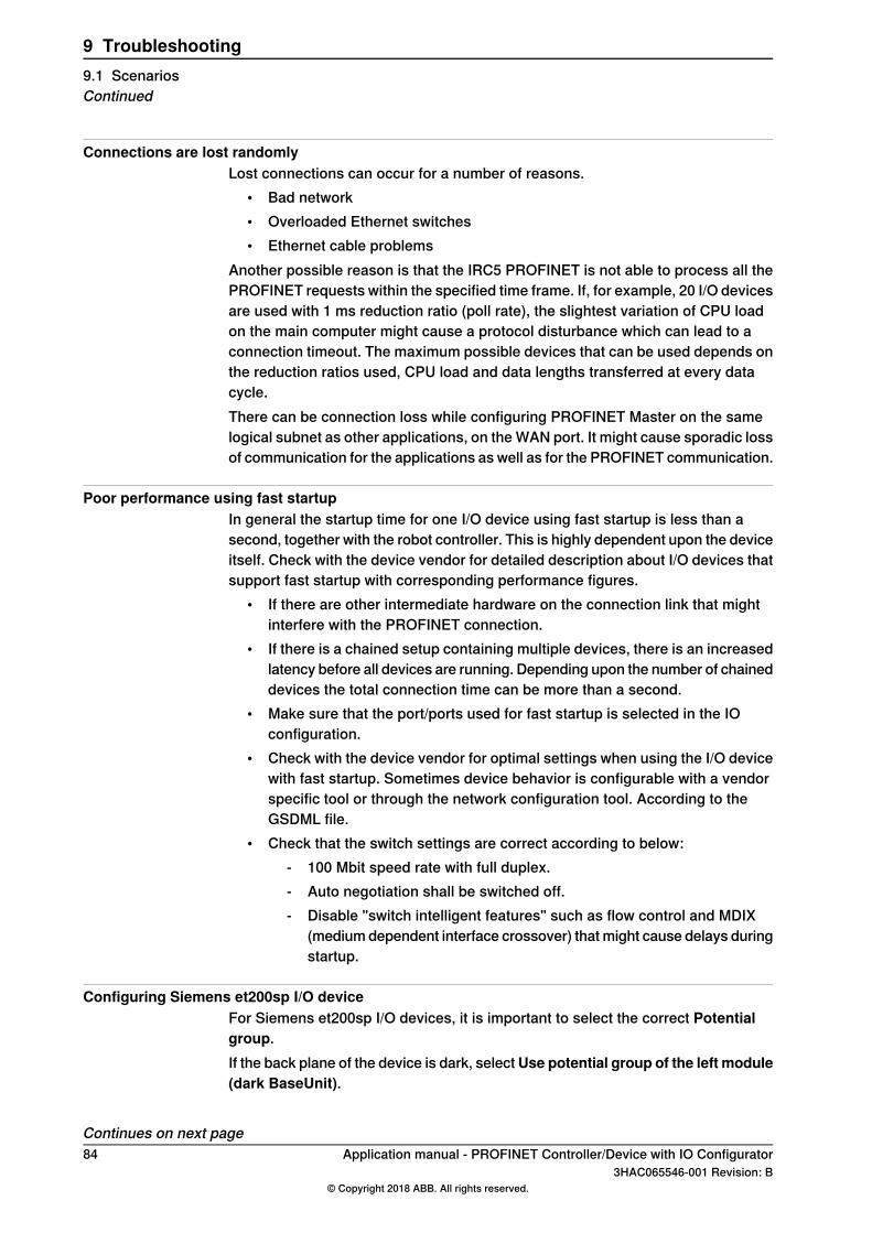
Connections are lost randomlyLost connections can occur for a number of reasons.
• Bad network• Overloaded Ethernet switches• Ethernet cable problems
Another possible reason is that the IRC5 PROFINET is not able to process all thePROFINET requests within the specified time frame. If, for example, 20 I/O devicesare used with 1 ms reduction ratio (poll rate), the slightest variation of CPU loadon the main computer might cause a protocol disturbance which can lead to aconnection timeout. The maximum possible devices that can be used depends onthe reduction ratios used, CPU load and data lengths transferred at every datacycle.There can be connection loss while configuring PROFINET Master on the samelogical subnet as other applications, on the WAN port. It might cause sporadic lossof communication for the applications as well as for the PROFINET communication.
Poor performance using fast startupIn general the startup time for one I/O device using fast startup is less than asecond, together with the robot controller. This is highly dependent upon the deviceitself. Check with the device vendor for detailed description about I/O devices thatsupport fast startup with corresponding performance figures.
• If there are other intermediate hardware on the connection link that mightinterfere with the PROFINET connection.
• If there is a chained setup containing multiple devices, there is an increasedlatency before all devices are running. Depending upon the number of chaineddevices the total connection time can be more than a second.
• Make sure that the port/ports used for fast startup is selected in the IOconfiguration.
• Check with the device vendor for optimal settings when using the I/O devicewith fast startup. Sometimes device behavior is configurable with a vendorspecific tool or through the network configuration tool. According to theGSDML file.
• Check that the switch settings are correct according to below:- 100 Mbit speed rate with full duplex.- Auto negotiation shall be switched off.- Disable "switch intelligent features" such as flow control and MDIX
(medium dependent interface crossover) that might cause delays duringstartup.
Configuring Siemens et200sp I/O deviceFor Siemens et200sp I/O devices, it is important to select the correct Potentialgroup.If the back plane of the device is dark, selectUse potential group of the left module(dark BaseUnit).
Continues on next page84 Application manual - PROFINET Controller/Device with IO Configurator
3HAC065546-001 Revision: B© Copyright 2018 ABB. All rights reserved.
9 Troubleshooting9.1 ScenariosContinued
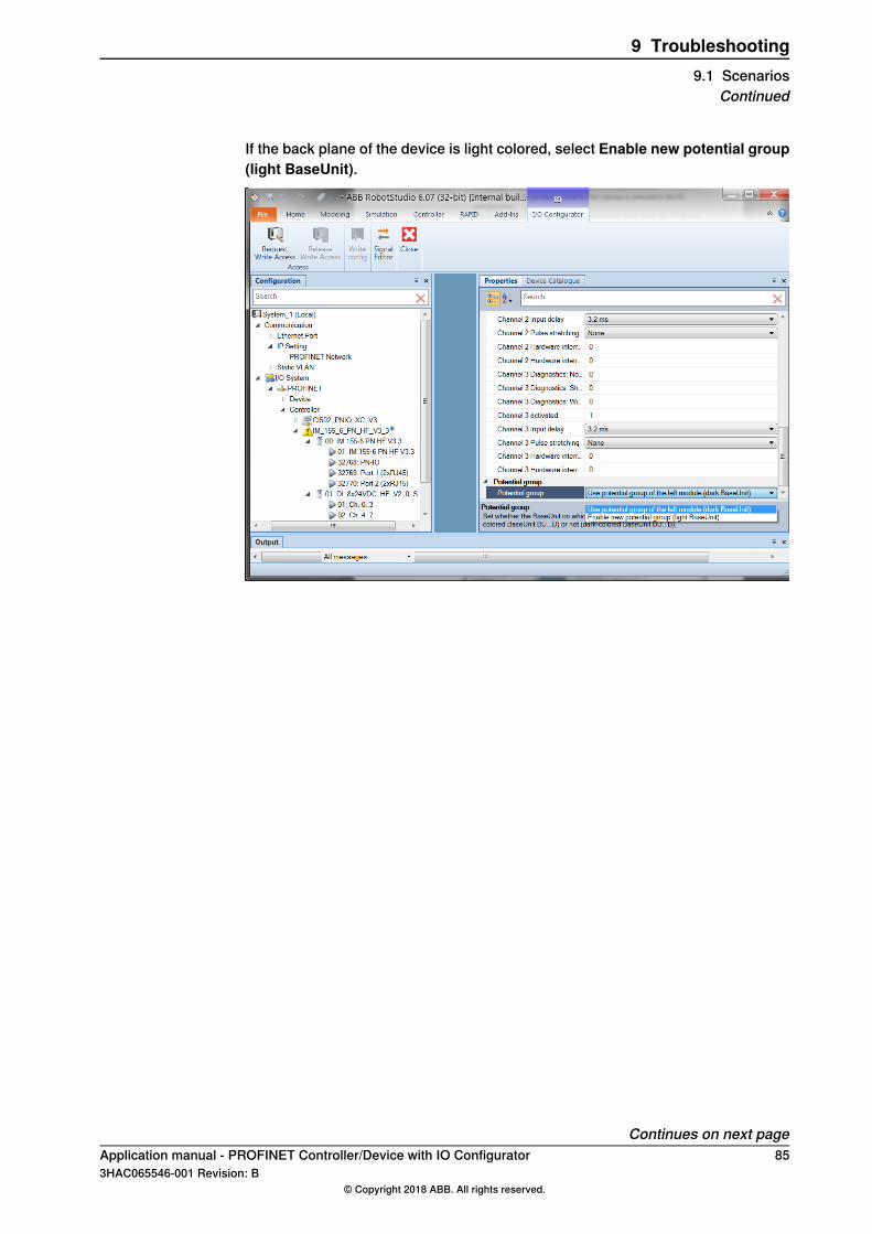
If the back plane of the device is light colored, select Enable new potential group(light BaseUnit).
Continues on next pageApplication manual - PROFINET Controller/Device with IO Configurator 853HAC065546-001 Revision: B
© Copyright 2018 ABB. All rights reserved.
9 Troubleshooting9.1 Scenarios
Continued
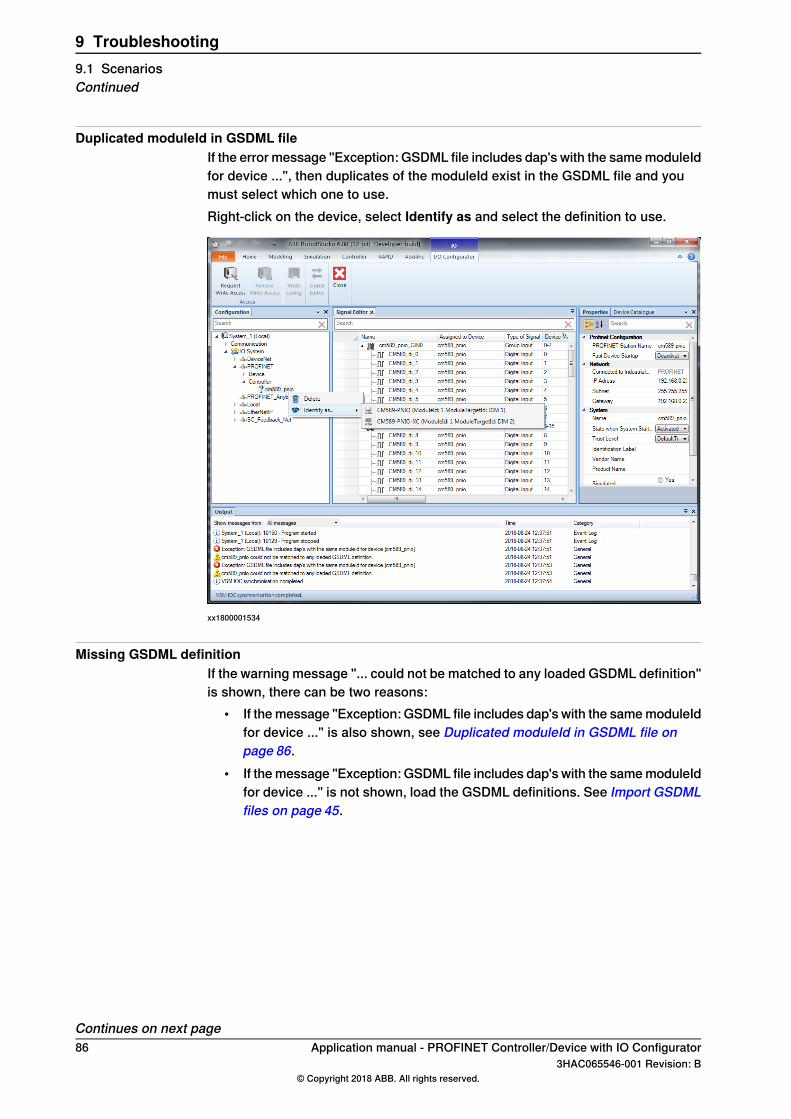
Duplicated moduleId in GSDML fileIf the error message "Exception: GSDML file includes dap's with the same moduleIdfor device ...", then duplicates of the moduleId exist in the GSDML file and youmust select which one to use.Right-click on the device, select Identify as and select the definition to use.
xx1800001534
Missing GSDML definitionIf the warning message "... could not be matched to any loaded GSDML definition"is shown, there can be two reasons:
• If the message "Exception: GSDML file includes dap's with the same moduleIdfor device ..." is also shown, see Duplicated moduleId in GSDML file onpage 86.
• If the message "Exception: GSDML file includes dap's with the same moduleIdfor device ..." is not shown, load the GSDML definitions. See Import GSDMLfiles on page 45.
Continues on next page86 Application manual - PROFINET Controller/Device with IO Configurator
3HAC065546-001 Revision: B© Copyright 2018 ABB. All rights reserved.
9 Troubleshooting9.1 ScenariosContinued
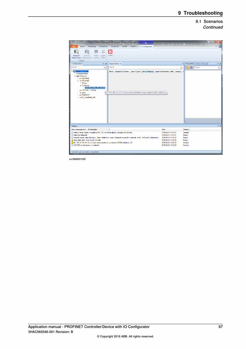
xx1800001535
Application manual - PROFINET Controller/Device with IO Configurator 873HAC065546-001 Revision: B
© Copyright 2018 ABB. All rights reserved.
9 Troubleshooting9.1 Scenarios
Continued

This page is intentionally left blank
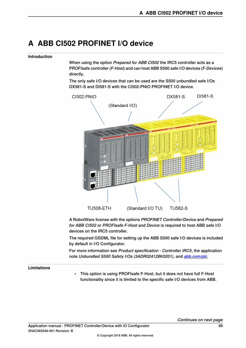
A ABB CI502 PROFINET I/O deviceIntroduction
When using the option Prepared for ABB CI502 the IRC5 controller acts as aPROFIsafe controller (F-Host) and can host ABB S500 safe I/O devices (F-Devices)directly.The only safe I/O devices that can be used are the S500 unbundled safe I/OsDX581-S and DI581-S with the CI502-PNIO PROFINET I/O device.
A RobotWare license with the options PROFINET Controller/Device and Preparedfor ABB CI502 or PROFIsafe F-Host and Device is required to host ABB safe I/Odevices on the IRC5 controller.The required GSDML file for setting up the ABB S500 safe I/O devices is includedby default in I/O Configurator.For more information see Product specification - Controller IRC5, the applicationnote Unbundled S500 Safety I/Os (3ADR024128K0201), and abb.com/plc.
Limitations• This option is using PROFIsafe F-Host, but it does not have full F-Host
functionality since it is limited to the specific safe I/O devices from ABB.
Continues on next pageApplication manual - PROFINET Controller/Device with IO Configurator 893HAC065546-001 Revision: B
© Copyright 2018 ABB. All rights reserved.
A ABB CI502 PROFINET I/O device
Install and configure the ABB S500 safe I/O devicesUse the following procedures to install and configure the ABB S500 safe I/O devices:
PrerequisitesIn addition to RobotStudio, the following tools are needed to be able to configurethe ABB S500 safe I/O devices:
• Download and install the ABB_AC500-S F_iPar_CRC Calculator tool fromthe RobotStudio Online Community, where it is included in the Tools andUtilities package. Once installed, it is started from the Vendor Tool buttonin the Safe IO Configurator in Visual SafeMove.
Configure ABB S500 in the IO Configurator1 Start RobotStudio, connect to the robot system where the ABB S500 safe
I/O devices are installed, and login as a safety user.2 Start the I/O Configurator from the Controller tab in RobotStudio.3 Configure the standard communication parameters for the network, i.e. ports,
IP-address, etc. This can also be configured from RobotStudio without usingthe Add-In.
4 Right-click the PROFINET node and select Scan Network to detect the I/Odevice.
Tip
Use the Blink functionality to detect the correct unit when multiple devicesare connected.
5 Add the detected device by right-clicking the device and selecting Add as.Select the configuration that corresponds to the physical device. The deviceis now displayed in the Configuration browser under thePROFINET/Controller node.
6 Add safe modules to the device from the Device Catalogue browser bydouble-clicking. When adding safe modules, they are also added in the SafeIO Configurator in Visual SafeMove.
7 Select the sub-module in theConfiguration browser and configure the modulesettings in the Properties browser, i.e. channel configuration, input delay,etc.
8 Configure the properties for the safe modules in the Properties browser.Set the following default values for each S500 safe module:
• Source Address: 1• Set the decimal Destination Address to the same address that is set
on the rotary switches on the device. Note that the values on the rotaryswitches are hexadecimal.
• Click the Vendor Tool button to open the ABB_AC500-S F_iPar_CRCCalculator tool and calculate the IParCrc value for the module. Copythe hexadecimal value into the Safe IO Configurator.
Continues on next page90 Application manual - PROFINET Controller/Device with IO Configurator
3HAC065546-001 Revision: B© Copyright 2018 ABB. All rights reserved.
A ABB CI502 PROFINET I/O deviceContinued
Note
Note that the I Par CRC checksum must be recalculated if the moduleconfiguration is changed, i.e. channel configuration, delay filter, etc.
Note
Note that the channel configuration for all inputs and outputs are by defaultdisabled and must be activated before an input or output can be used onthe specific channel.
9 The next step is to configure signals, seeConfigure signals on the ABB S500safe I/O devices on page 91.
Note
The signal configuration is not included in the IParCrc checksum.
10 Request write access and write the configuration to the controller. Restartthe controller.
Note
This requires that some basic SafeMove conditions are met, for examplea tool must have been created. For more information, see Applicationmanual - Functional safety and SafeMove2.
The communication to the S500 safe modules is now established which is alsoindicated by the status diodes on the devices.
Configure signals on the ABB S500 safe I/O devices1 Open the Signal Editor in IO Configurator.2 Configure safe input and output signals for the S500 safe modules. When
adding safe signals, they are available for use in the Safe IO Configurator inVisual SafeMove.
3 Request write access and write the configuration to the controller. Restartthe controller.
Note
If a signal is used by the safety module, for example in the combinatory logic, itcannot be renamed or removed from the signal editor. This is displayed with ashield symbol.
Application manual - PROFINET Controller/Device with IO Configurator 913HAC065546-001 Revision: B
© Copyright 2018 ABB. All rights reserved.
A ABB CI502 PROFINET I/O deviceContinued

This page is intentionally left blank
Index11241-1, 7
9997-2, 7997-1, 7
CCI502 PROFINET IO device, 89communication profiles, 15compatibility, 16configuration browser, 33configuration file, 13Connection, 65, 67controller, 16
Ddevice, 13, 16
EEnergy Saving, 75et200sp, 84external controller, 13external device, 13
FFast Device Startup, 53, 65–66, 70Fast Start Up, 13, 53FSU, 13, 53
GGSDML, 13GSDML file, 29, 31–32
Iindustrial Ethernet, 15Input Size, 30, 66, 80internal controller, 13internal device, 13
Mmaster, 13
Nnetwork security, 12
OOutput Size, 30, 66, 81Output window, 33
PPrioritized Startup, 13, 53private network, 22PROFINET
controller, 16device, 16internal device, 29standardization, 15
PROFINET versionsPROFIdrive, 15PROFIenergy, 15PROFINET-CBA, 15PROFINET-IO, 15–16PROFIsafe, 15
properties browser, 34
QQoS, 26Quality of Service, 26
Rreduction ratio, 13, 84ribbon, 33
Ssafety, 11scan editor, 34Scan Editor, 41Siemens et200sp, 84signal editor, 34Station Name, 65, 68symbols, 38system parameters, 65
Ttemplate I/O configuration file, 29topic I/O System
Device, 65Industrial Network, 65Internal Device, 66predefined internal device, 29predefined network, 29
Uuser interface, 33
Application manual - PROFINET Controller/Device with IO Configurator 933HAC065546-001 Revision: B
© Copyright 2018 ABB. All rights reserved.
Index


ABB AB, RoboticsRobotics and MotionS-721 68 VÄSTERÅS, SwedenTelephone +46 (0) 21 344 400
ABB AS, RoboticsRobotics and MotionNordlysvegen 7, N-4340 BRYNE, NorwayBox 265, N-4349 BRYNE, NorwayTelephone: +47 22 87 2000
ABB Engineering (Shanghai) Ltd.Robotics and MotionNo. 4528 Kangxin HighwayPuDong DistrictSHANGHAI 201319, ChinaTelephone: +86 21 6105 6666
ABB Inc.Robotics and Motion1250 Brown RoadAuburn Hills, MI 48326USATelephone: +1 248 391 9000
abb.com/robotics
3HAC065546-001,Rev
B,en
© Copyright 2018 ABB. All rights reserved.Specifications subject to change without notice.


![) PDS [] - DocumentID - 3428513 - Document Dated - - … 15861… · as per Restoration Plan prepared in 2005 and revised in 2006 (by Adi Associates ... PDS [] - DocumentID - 3428513](https://img.pdfslide.us/doc/110x75/5b92685009d3f2446f8bb960/-pds-documentid-3428513-document-dated-15861-as-per-restoration.jpg)