Embed Size (px)
Citation preview

ROBOTICS
Application manualArc and Arc Sensor

Trace back information:Workspace 21D version a10Checked in 2021-12-06Skribenta version 5.4.005
Application manualArc and Arc Sensor
RobotWare 6.13
Document ID: 3HAC050988-001Revision: H
© Copyright 2004-2021 ABB. All rights reserved.Specifications subject to change without notice.
The information in this manual is subject to change without notice and should notbe construed as a commitment by ABB. ABB assumes no responsibility for any errorsthat may appear in this manual.Except as may be expressly stated anywhere in this manual, nothing herein shall beconstrued as any kind of guarantee or warranty by ABB for losses, damage to personsor property, fitness for a specific purpose or the like.In no event shall ABB be liable for incidental or consequential damages arising fromuse of this manual and products described herein.This manual and parts thereof must not be reproduced or copied without ABB'swritten permission.Keep for future reference.Additional copies of this manual may be obtained from ABB.
Original instructions.
© Copyright 2004-2021 ABB. All rights reserved.Specifications subject to change without notice.
Table of contents7Overview of this manual ...................................................................................................................
91 Installation and setup
112 RobotWare - Arc Adaptive process control112.1 Adaptive Process Control ...................................................................................122.2 Seam tracking ..................................................................................................122.2.1 Seam tracking systems ............................................................................132.2.2 Seam tracking in different instructions ........................................................152.2.3 Optical tracking .......................................................................................162.2.4 WeldGuide .............................................................................................182.3 Sensor controlled tuning .....................................................................................192.4 Program controlled tuning ...................................................................................
213 Programming213.1 Programming for arc welding ...............................................................................263.2 Functions for arc welding when program execution has been stopped ........................323.3 Functions for arc welding during program execution ................................................
354 Programming RobotWare Arc systems with MultiMove354.1 RobotWare Arc with MultiMove ............................................................................364.2 Functions for arc welding when program execution has been stopped ........................414.3 Functions for arc welding during program execution ................................................424.4 Configuration ...................................................................................................464.5 Limitations .......................................................................................................
495 Weld Error Recovery495.1 Weld Error Recovery and error handling ................................................................515.2 Programming Weld Error Recovery ......................................................................605.3 Weld Error Recovery flowchart ............................................................................615.4 Configuring Weld Error Recovery .........................................................................635.5 Configure the recovery menu ..............................................................................655.6 Weld Error Recovery I/O interface ........................................................................745.7 Configure weld error recovery I/O Interface ............................................................765.8 User defined error handling .................................................................................785.9 Configure User defined error handling ...................................................................
816 Weld Repair816.1 Introduction ......................................................................................................836.2 Configuring Weld Repair .....................................................................................886.3 Best practice ....................................................................................................916.4 Full Automatic Mode ..........................................................................................986.5 Semi Automatic Mode ........................................................................................
1077 RAPID reference1077.1 Instructions ......................................................................................................1077.1.1 ArcC, ArcC1, ArcC2 - Arc welding with circular motion ...................................1157.1.2 ArcCEnd, ArcC1End, ArcC2End - Arc welding end with circular motion .............1237.1.3 ArcCStart, ArcC1Start, ArcC2Start - Arc welding start with circular motion .........1327.1.4 ArcL, ArcL1, ArcL2 - Arc welding with linear motion .......................................1407.1.5 ArcLEnd, ArcL1End, ArcL2End - Arc welding end with linear motion .................1487.1.6 ArcLStart, ArcL1Start, ArcL2Start - Arc welding start with linear motion .............1577.1.7 ArcMoveExtJ - Move one or several mechanical units without TCP ...................1597.1.8 ArcRefresh - Refresh arc weld data ............................................................1617.1.9 RecoveryMenu - Display the recovery menu .................................................
Application manual - Arc and Arc Sensor 53HAC050988-001 Revision: H
© Copyright 2004-2021 ABB. All rights reserved.
Table of contents
1637.1.10 RecoveryMenuWR - Display the recovery menu ............................................1657.1.11 RecoveryPosSet - Set the recovery position .................................................1687.1.12 RecoveryPosReset - Reset the recovery position ..........................................1707.1.13 SetWRProcName - Set name of process to re-execute ...................................1717.2 Data types .......................................................................................................1717.2.1 advSeamData - Advanced seam data ..........................................................1747.2.2 arcdata - Arc data ....................................................................................1767.2.3 flystartdata - Flying start data ....................................................................1777.2.4 seamdata - Seam data .............................................................................1837.2.5 trackdata - Seam tracking data ..................................................................1897.2.6 weavedata - Weave data ...........................................................................1967.2.7 welddata - Weld data ...............................................................................
2018 System parameters2018.1 Introduction ......................................................................................................2038.2 The group Arc System ........................................................................................2038.2.1 The type Arc System settings ....................................................................2048.2.2 The type Arc System Properties .................................................................2088.2.3 The type Arc Robot Properties ...................................................................2128.2.4 The type Arc Units ...................................................................................2138.2.5 The type Arc Equipment ...........................................................................2148.2.6 The type Arc Equipment Class ...................................................................2158.3 The group Generic Equipment Class .....................................................................2158.3.1 The type Arc Equipment Properties ............................................................2198.3.2 The type Arc Equipment Digital Inputs ........................................................2228.3.3 The type Arc Equipment Digital Outputs ......................................................2248.3.4 The type Arc Equipment Analog Outputs .....................................................2258.3.5 The type Arc Equipment Analog Inputs ........................................................2268.3.6 The type Arc Equipment Group Outputs ......................................................2278.4 The group Optical Sensor ...................................................................................2278.4.1 The type Optical Sensor ...........................................................................2288.4.2 The type Optical Sensor Properties ............................................................2318.5 Configurable error handling .................................................................................2338.6 Data masking ...................................................................................................2378.7 Welder Ready Supervision for StdIoWelder interface ...............................................
241Index
6 Application manual - Arc and Arc Sensor3HAC050988-001 Revision: H
© Copyright 2004-2021 ABB. All rights reserved.
Table of contents
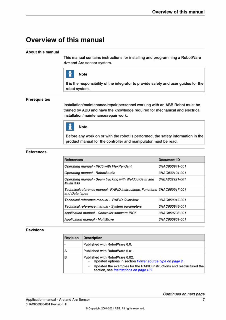
Overview of this manualAbout this manual
This manual contains instructions for installing and programming a RobotWareArc and Arc sensor system.
Note
It is the responsibility of the integrator to provide safety and user guides for therobot system.
PrerequisitesInstallation/maintenance/repair personnel working with an ABB Robot must betrained by ABB and have the knowledge required for mechanical and electricalinstallation/maintenance/repair work.
Note
Before any work on or with the robot is performed, the safety information in theproduct manual for the controller and manipulator must be read.
References
Document IDReferences
3HAC050941-001Operating manual - IRC5 with FlexPendant
3HAC032104-001Operating manual - RobotStudio
3HEA802921-001Operating manual - Seam tracking with Weldguide III andMultiPass
3HAC050917-001Technical referencemanual - RAPID Instructions, Functionsand Data types
3HAC050947-001Technical reference manual - RAPID Overview
3HAC050948-001Technical reference manual - System parameters
3HAC050798-001Application manual - Controller software IRC5
3HAC050961-001Application manual - MultiMove
Revisions
DescriptionRevision
Published with RobotWare 6.0.-
Published with RobotWare 6.01.A
Published with RobotWare 6.02.• Updated options in section Power source type on page 9.• Updated the examples for the RAPID instructions and restructured the
section, see Instructions on page 107.
B
Continues on next pageApplication manual - Arc and Arc Sensor 73HAC050988-001 Revision: H
© Copyright 2004-2021 ABB. All rights reserved.
Overview of this manual
DescriptionRevision
Published with RobotWare 6.04.• The manual is partly restructured.• Added information about flying start.• Minor corrections.
C
Published with RobotWare 6.05.• Added information about Pre Process Tracking.• Minor corrections.
D
Published with RobotWare 6.07.• Protocol LTPROTOBUF added to sensor interface.• Added track mode 13, 14 and 15 to section trackdata - Seam tracking
data on page 183.• Minor corrections.
E
Published with RobotWare 6.09.• Updated information for ArcMoveExtJ.• Limitation information updated for instructions:
ArcC, ArcC1, ArcC2ArcCEnd, ArcC1End, ArcC2EndArcCStart, ArcC1Start, ArcC2StartArcL, ArcL1, ArcL2ArcLEnd, ArcL1End, ArcL2EndArcLStart, ArcL1Start, ArcL2StartArcMoveExtJ
ArcRefresh
• Updated information for WeldRepair with FlexPositioner.• Added information about Add-Ins, see Power source type on page 9.• Added StopMode, see The type Arc SystemProperties on page204 and
The type Arc Robot Properties on page 208.
F
Published with RobotWare 6.11.• Added limitation for seamdata.
G
Published with RobotWare 6.13.• Added WelderReady supervision for standard I/O welder.
H
8 Application manual - Arc and Arc Sensor3HAC050988-001 Revision: H
© Copyright 2004-2021 ABB. All rights reserved.
Overview of this manualContinued
1 Installation and setupInstallation options
The installation of RobotWare Arc can be customized to fit various applicationdemands, such as a different power source types and MultiMove support.The following options can be selected in RobotStudio when creating the system,and then customized according to application demands:
• Power source type• 651-1 Additional Arc Systems• 660-1 Optical Tracking Arc
Tip
How to create systems in RobotStudio is described in Operatingmanual - RobotStudio.
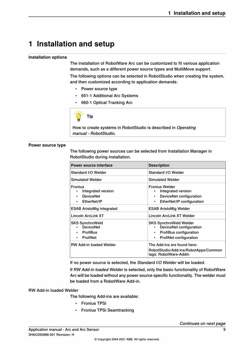
Power source typeThe following power sources can be selected from Installation Manager inRobotStudio during installation.
DescriptionPower source interface
Standard I/O WelderStandard I/O Welder
Simulated WelderSimulated Welder
Fronius Welder• Integrated version• DeviceNet configuration• EtherNet/IP configuration
Fronius• Integrated version• DeviceNet• EtherNet/IP
ESAB AristoMig WelderESAB AristoMig integrated
Lincoln ArcLink XT WelderLincoln ArcLink XT
SKS SynchroWeld Welder• DeviceNet configuration• ProfiBus configuration• ProfiNet configuration
SKS SynchroWeld• DeviceNet• ProfiBus• ProfiNet
The Add-ins are found here:RW Add-in loaded WelderRobotStudio/Add-ins/RobotApps/Commontags: RobotWare-Addin
If no power source is selected, the Standard I/O Welder will be loaded.If RW Add-in loaded Welder is selected, only the basic functionality of RobotWareArc will be loaded without any power source specific functionality. The welder mustbe loaded from a RobotWare Add-in.
RW Add-in loaded WelderThe following Add-ins are available:
• Fronius TPSi• Fronius TPSi Seamtracking
Continues on next pageApplication manual - Arc and Arc Sensor 93HAC050988-001 Revision: H
© Copyright 2004-2021 ABB. All rights reserved.
1 Installation and setup
• Miller EIP Welder (Miller Ethernet IP welder)• Lincoln ArcLink/XT
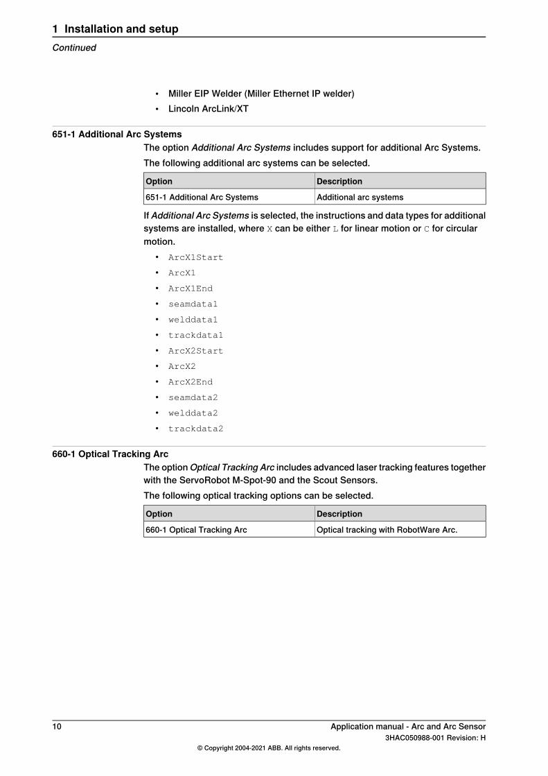
651-1 Additional Arc SystemsThe option Additional Arc Systems includes support for additional Arc Systems.The following additional arc systems can be selected.
DescriptionOption
Additional arc systems651-1 Additional Arc Systems
If Additional Arc Systems is selected, the instructions and data types for additionalsystems are installed, where X can be either L for linear motion or C for circularmotion.
• ArcX1Start
• ArcX1
• ArcX1End
• seamdata1
• welddata1
• trackdata1
• ArcX2Start
• ArcX2
• ArcX2End
• seamdata2
• welddata2
• trackdata2
660-1 Optical Tracking ArcThe optionOptical Tracking Arc includes advanced laser tracking features togetherwith the ServoRobot M-Spot-90 and the Scout Sensors.The following optical tracking options can be selected.
DescriptionOption
Optical tracking with RobotWare Arc.660-1 Optical Tracking Arc
10 Application manual - Arc and Arc Sensor3HAC050988-001 Revision: H
© Copyright 2004-2021 ABB. All rights reserved.
1 Installation and setupContinued
2 RobotWare - Arc Adaptive process control2.1 Adaptive Process Control
DescriptionThe optionsOptical tracking Arc [660-1] and WeldGuide [815-1] are for arc weldingapplications where welding data or path must be dynamically changed during thewelding to adapt to changes in geometry or material. In addition to the basicRobotWare-Arc package, the options also include functions for Adaptive ProcessControl and Statistical Process Control.Adaptive Process Control is divided into three groups:
• Seam tracking: This is used when sensor signals are used, while welding aseam, to correct the path of the robot, thus tracking the real seam. This isuseful, for example, if parts are not placed in exactly the same position eachtime or if the seam geometry can vary. See Seam tracking on page 12.
• Sensor controlled tuning: This is used when sensor signals are used toupdate the process data used while welding. This is useful, for example, ifthe seam features vary while the robot is welding. See Sensor controlledtuning on page 18.
• Program controlled tuning: This is used when welding data is changedautomatically and is related to the path or position. See Program controlledtuning on page 19.
Application manual - Arc and Arc Sensor 113HAC050988-001 Revision: H
© Copyright 2004-2021 ABB. All rights reserved.
2 RobotWare - Arc Adaptive process control2.1 Adaptive Process Control
2.2 Seam tracking
2.2.1 Seam tracking systems
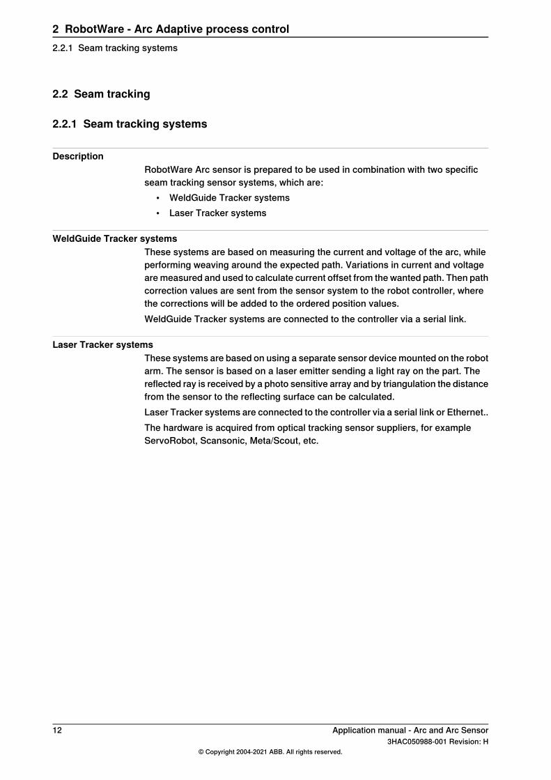
DescriptionRobotWare Arc sensor is prepared to be used in combination with two specificseam tracking sensor systems, which are:
• WeldGuide Tracker systems• Laser Tracker systems
WeldGuide Tracker systemsThese systems are based on measuring the current and voltage of the arc, whileperforming weaving around the expected path. Variations in current and voltageare measured and used to calculate current offset from the wanted path. Then pathcorrection values are sent from the sensor system to the robot controller, wherethe corrections will be added to the ordered position values.WeldGuide Tracker systems are connected to the controller via a serial link.
Laser Tracker systemsThese systems are based on using a separate sensor device mounted on the robotarm. The sensor is based on a laser emitter sending a light ray on the part. Thereflected ray is received by a photo sensitive array and by triangulation the distancefrom the sensor to the reflecting surface can be calculated.Laser Tracker systems are connected to the controller via a serial link or Ethernet..The hardware is acquired from optical tracking sensor suppliers, for exampleServoRobot, Scansonic, Meta/Scout, etc.
12 Application manual - Arc and Arc Sensor3HAC050988-001 Revision: H
© Copyright 2004-2021 ABB. All rights reserved.
2 RobotWare - Arc Adaptive process control2.2.1 Seam tracking systems
2.2.2 Seam tracking in different instructions
Seam tracking in arc welding instructionsThe ArcX instructions can be used for seam tracking in the following ways.If the system is configured for the use of a WeldGuide Tracker or Laser Tracker,then the optional argument \Track shall be used to control the tracking function.With this argument it is possible to specify the track data to be used for the specificArcX instruction.The communication between WeldGuide Tracker system or Laser Tracker systemand the controller is via a serial link or via Ethernet (TCP/IP) using a specific linkprotocol (RTP1) and a specific application protocol (LTAPP / LTPROTOBUF). Theoption Optical Tracking Arc or WeldGuide is needed.If the system is not configured for a WeldGuide Tracker or Laser Tracker seamtracking, that is, none of these parameters are set, then the ArcX instructions willwork for path corrections using CorrXXX instructions. Then the optional argument\Corr must be used in these instructions instead of \Track. The option PathOffset is needed.
Seam tracking in other movement instructionsFor ordinary movement instructions like MoveL or MoveC also path corrections canbe done. Then the optional argument \Corr must be used in these movementinstructions. The path corrections will then be programmed using CorrXXX
instructions, see below. These instructions are only available if the option PathOffset or the option RobotWare-Arc sensor are installed.If the correction values are fetched from an external sensor, then the communicationbetween sensor and robot controller can be via a serial link. Also in this caseSensor Interface or RobotWare-Arc sensor options should be used, which willinclude instructions for the serial communication using a specific link protocol(RTP1) and a specific application protocol (LTAPP / LTPROTOBUF) (see shortdescription below and Application manual - Controller software IRC5, sectionSensor Interface).
Path correction instructionsThese instructions, included in the option Path offset, describe the path correction.The following instructions and data types are available:
• CorrClear• CorrCon• CorrDiscon• CorrRead• CorrWrite• Data type: corrdescr
These instructions and the data type will make it possible to add certain offsets toa programmed path, while the robot is moving. The offsets to add can be valuesgiven from a sensor connected to the system via e.g. serial link or via analog input.
Continues on next pageApplication manual - Arc and Arc Sensor 133HAC050988-001 Revision: H
© Copyright 2004-2021 ABB. All rights reserved.
2 RobotWare - Arc Adaptive process control2.2.2 Seam tracking in different instructions
Sensor interfaceThis is the same as the separate option Sensor Interface. The option, included inOptical Tracking or WeldGuide, will make serial communication possible with anexternal sensor or other unit. The communication will use the link protocol RTP1.With this function it is possible to read data from or write data to the sensor usingthe instructions listed below. Thus it will be possible to use sensor data for pathcorrections or for process tuning. The following instructions will be included forthe data communication:
• IVarValue• ReadBlock• ReadVar• WriteBlock• WriteVar
Note
Path corrections for ArcX instructions can be done in two ways as indicatedabove.
• In system which are not configured for WeldGuide or Laser Tracker, theinstructions Corrxxx (see above) must be used to write the correctionvalues to a correction generator
• In system configured for serialWeldGuide or Laser Tracker, path correctionswill be automatically active if the \Track argument is used, where the trackdata to be used is included. This requires that the application protocol LTAPPor LTPROTOBUF is used for the communication with the sensor.
14 Application manual - Arc and Arc Sensor3HAC050988-001 Revision: H
© Copyright 2004-2021 ABB. All rights reserved.
2 RobotWare - Arc Adaptive process control2.2.2 Seam tracking in different instructionsContinued
2.2.3 Optical tracking
PrerequisitesIf the system is configured for the use of an optical tracker, then the optionalargument \Track shall be used to control the tracking function. With this argumentit is possible to specify the track data to be used for the specific ArcX instruction.If the \Track argument is not included, no seam tracking will be active.As an optical tracker is mounted in front of the weld gun and measures the actualseam position in advance, the first part of the seam has no tracking data available.Therefore the distance between the first sensor measurement position and thestart of the seam will not be tracked. To avoid this problem you can use the optionalargument \PreProcessTracking, which activates Pre Process TrackingFor more information see Operating manual - Tracking and searching with opticalsensors.
MoveL p10,v1000,fine,tWeldGun;
ArcLStart p20,v1000,sm1,wdHD\Weave:=wv4,fine,tWeldGun\Track:=tr1;
ArcLEnd p30,v1000,sm1,wdHD\Weave:=wv4,fine,tWeldGun\Track:=tr1;
The laser sensor needs to be calibrated to have optimal performance. That is donevia the calibration programs delivered with the Sensor option. The result from thatcalibration ends up in a RAPID variable of type pose. The name of this variableshould be specified in the configuration parameters for the optical tracker.
Application manual - Arc and Arc Sensor 153HAC050988-001 Revision: H
© Copyright 2004-2021 ABB. All rights reserved.
2 RobotWare - Arc Adaptive process control2.2.3 Optical tracking
2.2.4 WeldGuide
Tracking methodsA WeldGuide tracking system uses the arc as a sensor to adapt the robot path tothe actual location of the part. Measuring the arc voltage and welding current,synchronized with the robot weave pattern, the stick-out length is calculated onboth sides and in the middle of the weld. The stick-out length in the middle andthe difference between the sides are converted in to robot vertical and horizontalcorrections.Adaptive welding. A further enhancement is to use the same data to adapt therobot weave width and travel speed in order to fill a groove that can vary in size.More information about WeldGuide tracking can be found in Operatingmanual - Seam tracking with Weldguide IV and MultiPass.
Path correction instructionsThese instructions, included in the option Path offset, describe the path correction.The following instructions and data types are available:
• CorrClear
• CorrCon
• CorrDiscon
• CorrRead
• CorrWrite
• Data type: corrdescrThese instructions and the data type will make it possible to add certain offsets toa programmed path, while the robot is moving. The offsets to add can be valuesgiven from a sensor connected to the system via e.g. serial link or via analog input.
Sensor interfaceThis is the same as the separate option Sensor Interface. The option, included inRobotWare-Arc sensor, will make serial communication possible with an externalsensor or other unit. The communication will use the link protocol RTP1. With thisfunction it is possible to read data from or write data to the sensor using theinstructions listed below. Thus it will be possible to use sensor data for pathcorrections or for process tuning.The following instructions will be included for the data communication:
• IVarValue
• ReadBlock
• ReadVar
• WriteBlock
• WriteVar
Continues on next page16 Application manual - Arc and Arc Sensor
3HAC050988-001 Revision: H© Copyright 2004-2021 ABB. All rights reserved.
2 RobotWare - Arc Adaptive process control2.2.4 WeldGuide
Note
Path corrections for ArcL/ArcC instructions can be done in two ways as indicatedabove.
• In system which are not configured for WeldGuide or Laser Tracker, theinstructions Corrxxx (see above) must be used to write the correctionvalues to a correction generator.
• In system configured for WeldGuide or Laser Tracker, path corrections willbe automatically active if the \Track argument is used, where the trackdata to be used is included. This requires that the application protocol LTAPPor LTPROTOBUF is used for the communication with the sensor.
Related information
Described inInformation
System parameters on page 201Installation parameters for welding equipmentand functions
trackdata - Seam tracking data on page 183trackdata - seam tracking data
660-1 Optical Tracking Arc on page 10Installation and setup
Applicationmanual - Controller software IRC5Sensor Interface
ArcL, ArcL1, ArcL2 - Arc welding with linearmotion on page 132
Arc welding instructions
ArcC, ArcC1, ArcC2 - Arc welding with circu-lar motion on page 107
Application manual - Arc and Arc Sensor 173HAC050988-001 Revision: H
© Copyright 2004-2021 ABB. All rights reserved.
2 RobotWare - Arc Adaptive process control2.2.4 WeldGuide
Continued
2.3 Sensor controlled tuning
DescriptionSensor controlled tuning provides a powerful tool for changing/tuning a processduring the execution of a weld due to the input signals from a sensor.Example of application are change process data like voltage, wire feed, speedbased on current sensor values for seam volume or gap detected by a sensor.The function is generally used in connection with trap routines and interrupts wherethe instruction ArcRefresh can be used to update the weld data. Thecommunication with the external sensor, which provides the feedback data, canfor instance be done using the option Sensor Interface, which is included inRobotWare-Arc sensor.
18 Application manual - Arc and Arc Sensor3HAC050988-001 Revision: H
© Copyright 2004-2021 ABB. All rights reserved.
2 RobotWare - Arc Adaptive process control2.3 Sensor controlled tuning
2.4 Program controlled tuning
DescriptionProgram controlled tuning means that the weld data can be changed during weldingrelated to specific positions on the path or other known geometry changes.Example of application are:
• Change process data with reference to a time or distance before or after adefined position
• Change the wire feed speed with reference to the volume of the seam• Set up a heat pulse variation along a seam• Set up high penetration on one side of a seam and low penetration on the
other side• Initiate a ramp-down towards the end of a weld
The function is generally used in connection with trap routines and interrupts wherethe instruction ArcRefresh can be used to update the welddata.
Application manual - Arc and Arc Sensor 193HAC050988-001 Revision: H
© Copyright 2004-2021 ABB. All rights reserved.
2 RobotWare - Arc Adaptive process control2.4 Program controlled tuning

This page is intentionally left blank
3 Programming3.1 Programming for arc welding
PrerequisitesBefore creating an arc welding program, the arc welding system or systems (seeDefining arc welding systems on page 202) and additional axes, if any, must beconfigured. This configuration is described in System parameters on page 201.
Program structureWhen there are several seams to be welded on an object, the welding sequencemay be of critical importance for the quality of the object. The risk of deformationdue to thermal stress can be reduced by choosing a suitable seam weldingsequence. It is often best to make a specific routine, object routine, for this withall the seams specified in the correct order. When the object is placed in apositioner, its orientation can also be specified in the object routine. The objectroutine can call a welding routine for each seam to be welded.
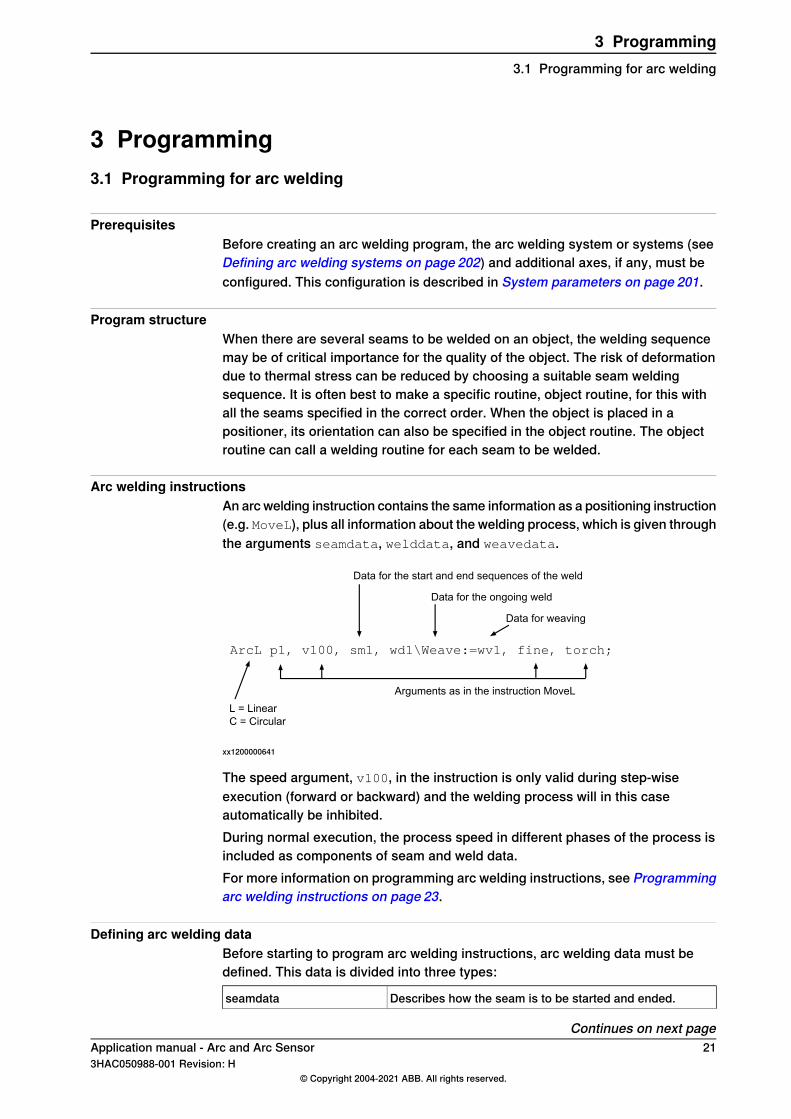
Arc welding instructionsAn arc welding instruction contains the same information as a positioning instruction(e.g. MoveL), plus all information about the welding process, which is given throughthe arguments seamdata, welddata, and weavedata.
Data for the start and end sequences of the weld
Data for the ongoing weld
Data for weaving
L = LinearC = Circular
Arguments as in the instruction MoveL
ArcL p1, v100, sm1, wd1\Weave:=wv1, fine, torch;
xx1200000641
The speed argument, v100, in the instruction is only valid during step-wiseexecution (forward or backward) and the welding process will in this caseautomatically be inhibited.During normal execution, the process speed in different phases of the process isincluded as components of seam and weld data.For more information on programming arc welding instructions, see Programmingarc welding instructions on page 23.
Defining arc welding dataBefore starting to program arc welding instructions, arc welding data must bedefined. This data is divided into three types:
Describes how the seam is to be started and ended.seamdata
Continues on next pageApplication manual - Arc and Arc Sensor 213HAC050988-001 Revision: H
© Copyright 2004-2021 ABB. All rights reserved.
3 Programming3.1 Programming for arc welding
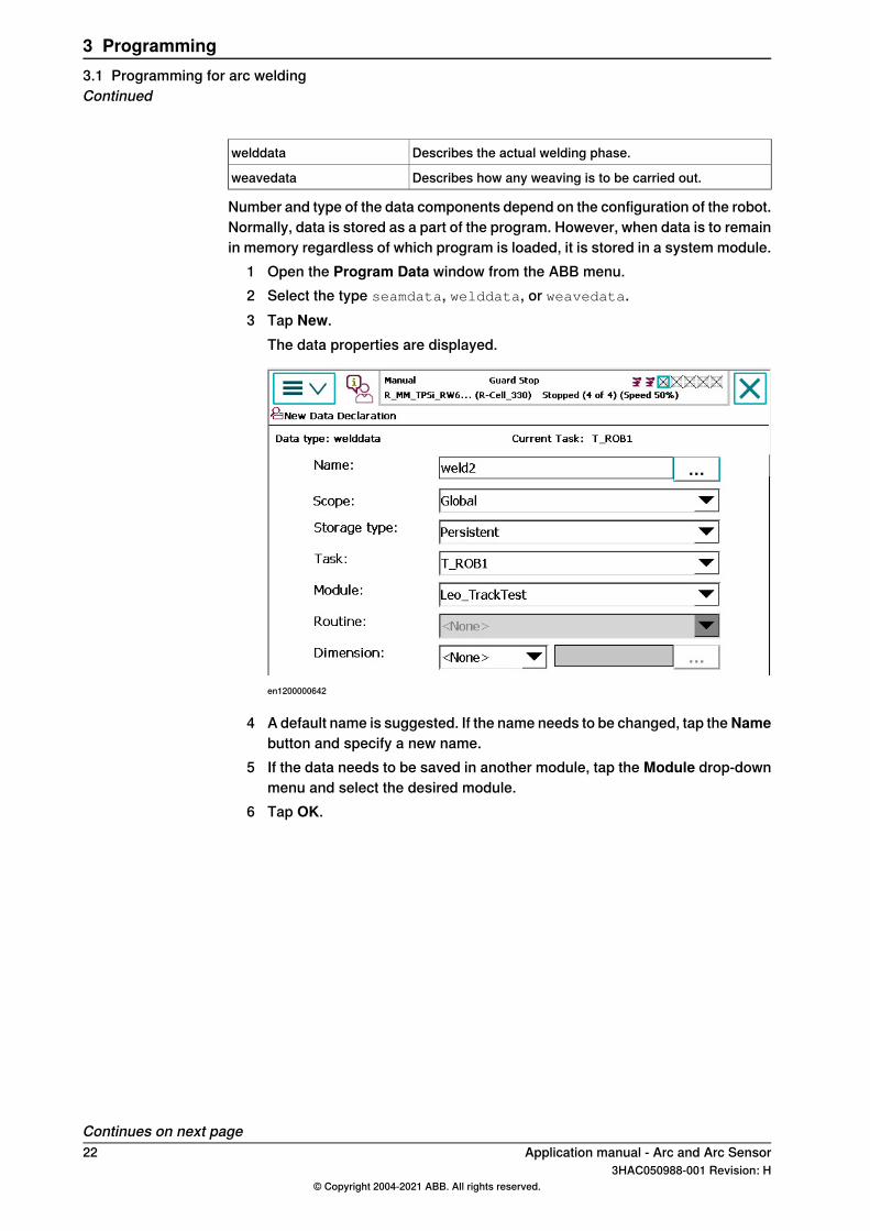
Describes the actual welding phase.welddata
Describes how any weaving is to be carried out.weavedata
Number and type of the data components depend on the configuration of the robot.Normally, data is stored as a part of the program. However, when data is to remainin memory regardless of which program is loaded, it is stored in a system module.
1 Open the Program Data window from the ABB menu.2 Select the type seamdata, welddata, or weavedata.3 Tap New.
The data properties are displayed.
en1200000642
4 A default name is suggested. If the name needs to be changed, tap theNamebutton and specify a new name.
5 If the data needs to be saved in another module, tap the Module drop-downmenu and select the desired module.
6 Tap OK.
Continues on next page22 Application manual - Arc and Arc Sensor
3HAC050988-001 Revision: H© Copyright 2004-2021 ABB. All rights reserved.
3 Programming3.1 Programming for arc weldingContinued
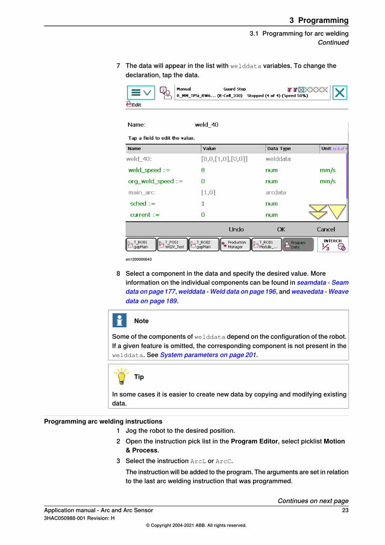
7 The data will appear in the list with welddata variables. To change thedeclaration, tap the data.
en1200000643
8 Select a component in the data and specify the desired value. Moreinformation on the individual components can be found in seamdata - Seamdata on page177,welddata -Weld data on page196, andweavedata -Weavedata on page 189.
Note
Some of the components of welddata depend on the configuration of the robot.If a given feature is omitted, the corresponding component is not present in thewelddata. See System parameters on page 201.
Tip
In some cases it is easier to create new data by copying and modifying existingdata.
Programming arc welding instructions1 Jog the robot to the desired position.2 Open the instruction pick list in the Program Editor, select picklist Motion
& Process.3 Select the instruction ArcL or ArcC.
The instruction will be added to the program. The arguments are set in relationto the last arc welding instruction that was programmed.
Continues on next pageApplication manual - Arc and Arc Sensor 233HAC050988-001 Revision: H
© Copyright 2004-2021 ABB. All rights reserved.
3 Programming3.1 Programming for arc welding
Continued
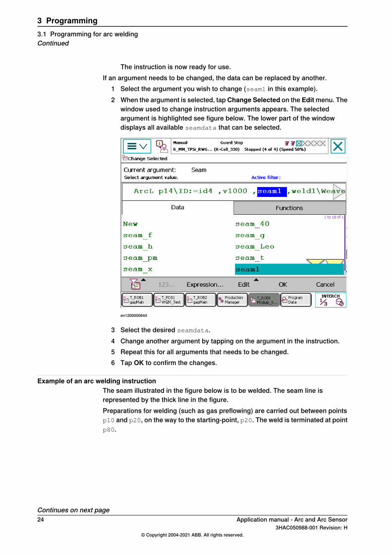
The instruction is now ready for use.If an argument needs to be changed, the data can be replaced by another.
1 Select the argument you wish to change (seam1 in this example).2 When the argument is selected, tap Change Selected on the Edit menu. The
window used to change instruction arguments appears. The selectedargument is highlighted see figure below. The lower part of the windowdisplays all available seamdata that can be selected.
en1200000644
3 Select the desired seamdata.4 Change another argument by tapping on the argument in the instruction.5 Repeat this for all arguments that needs to be changed.6 Tap OK to confirm the changes.
Example of an arc welding instructionThe seam illustrated in the figure below is to be welded. The seam line isrepresented by the thick line in the figure.Preparations for welding (such as gas preflowing) are carried out between pointsp10 and p20, on the way to the starting-point, p20. The weld is terminated at pointp80.
Continues on next page24 Application manual - Arc and Arc Sensor
3HAC050988-001 Revision: H© Copyright 2004-2021 ABB. All rights reserved.
3 Programming3.1 Programming for arc weldingContinued
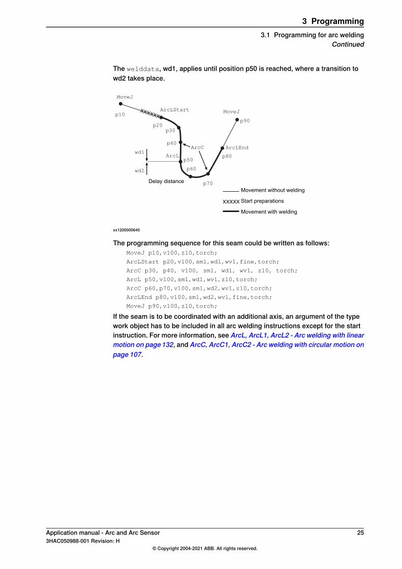
The welddata, wd1, applies until position p50 is reached, where a transition towd2 takes place.
xxxxxx
xxxxx
p10
p20p30
p40
p50
p60
p70
p80
p90
MoveJ
ArcLStart
ArcL
MoveJ
ArcC ArcLEndwd1
wd2
Delay distanceMovement without welding
Start preparations
Movement with welding
xx1200000645
The programming sequence for this seam could be written as follows:MoveJ p10,v100,z10,torch;
ArcLStart p20,v100,sm1,wd1,wv1,fine,torch;
ArcC p30, p40, v100, sm1, wd1, wv1, z10, torch;
ArcL p50,v100,sm1,wd1,wv1,z10,torch;
ArcC p60,p70,v100,sm1,wd2,wv1,z10,torch;
ArcLEnd p80,v100,sm1,wd2,wv1,fine,torch;
MoveJ p90,v100,z10,torch;
If the seam is to be coordinated with an additional axis, an argument of the typework object has to be included in all arc welding instructions except for the startinstruction. For more information, see ArcL, ArcL1, ArcL2 - Arc welding with linearmotion on page132, and ArcC, ArcC1, ArcC2 - Arc welding with circular motion onpage 107.
Application manual - Arc and Arc Sensor 253HAC050988-001 Revision: H
© Copyright 2004-2021 ABB. All rights reserved.
3 Programming3.1 Programming for arc welding
Continued
3.2 Functions for arc welding when program execution has been stopped
Manual modeArc welding functions (program execution has been stopped) in manual mode:
• Weld data tuning• Weave data tuning• Communicate with seam tracker sensor• Process blocking• Manual wire feed• Manual gas on/off• Select arc welding system• Changing tuning increments
Note
If a window is open in Manual mode and the functionality is disabled in Automode, switching from Manual to Auto mode will close the window.
Auto modeArc welding functions (program execution has been stopped) in Auto mode:
• Manual wire feed• Manual gas on/off• Select arc welding system• Changing tuning increments
Note
If a window is open in Manual mode and the functionality is disabled in Automode, switching from Manual to Auto mode will close the window.
Continues on next page26 Application manual - Arc and Arc Sensor
3HAC050988-001 Revision: H© Copyright 2004-2021 ABB. All rights reserved.
3 Programming3.2 Functions for arc welding when program execution has been stopped
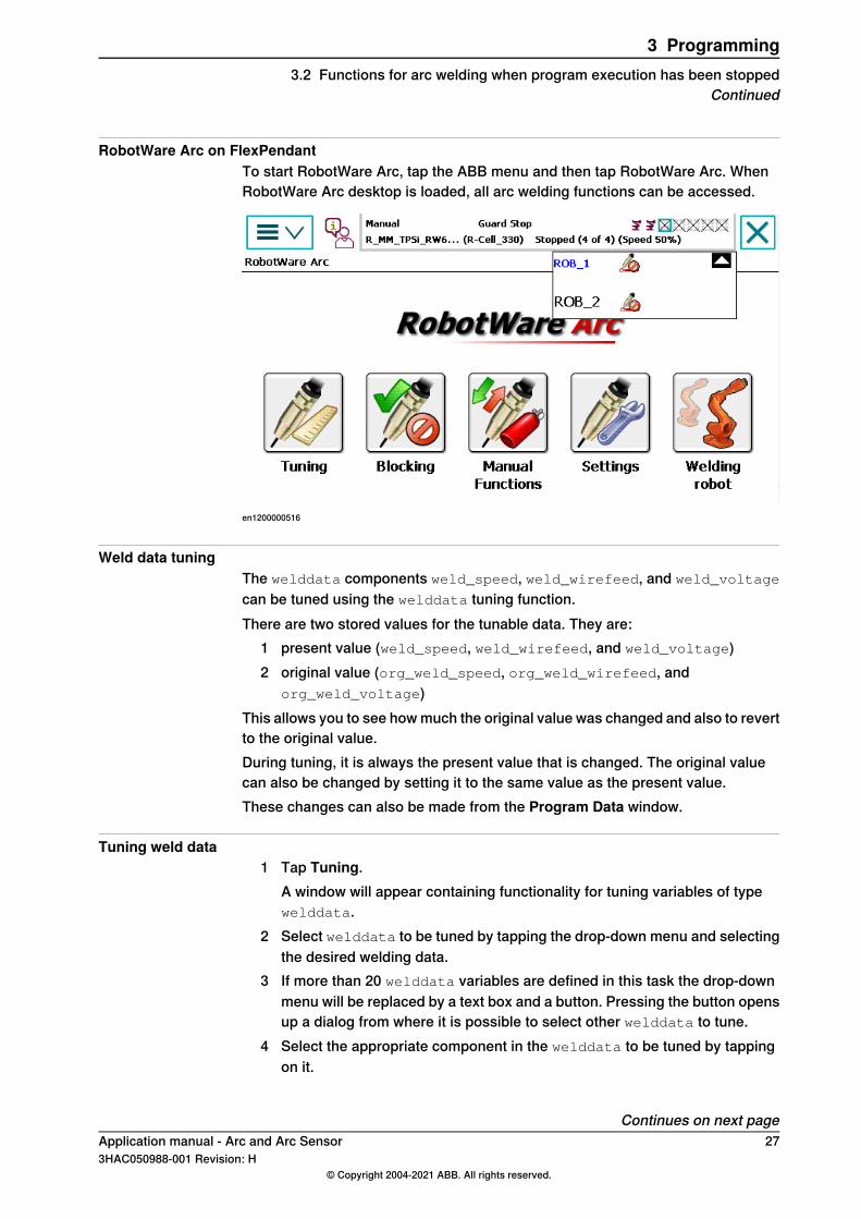
RobotWare Arc on FlexPendantTo start RobotWare Arc, tap the ABB menu and then tap RobotWare Arc. WhenRobotWare Arc desktop is loaded, all arc welding functions can be accessed.
en1200000516
Weld data tuningThe welddata components weld_speed, weld_wirefeed, and weld_voltage
can be tuned using the welddata tuning function.There are two stored values for the tunable data. They are:
1 present value (weld_speed, weld_wirefeed, and weld_voltage)2 original value (org_weld_speed, org_weld_wirefeed, and
org_weld_voltage)This allows you to see how much the original value was changed and also to revertto the original value.During tuning, it is always the present value that is changed. The original valuecan also be changed by setting it to the same value as the present value.These changes can also be made from the Program Data window.
Tuning weld data1 Tap Tuning.
A window will appear containing functionality for tuning variables of typewelddata.
2 Select welddata to be tuned by tapping the drop-down menu and selectingthe desired welding data.
3 If more than 20 welddata variables are defined in this task the drop-downmenu will be replaced by a text box and a button. Pressing the button opensup a dialog from where it is possible to select other welddata to tune.
4 Select the appropriate component in the welddata to be tuned by tappingon it.
Continues on next pageApplication manual - Arc and Arc Sensor 273HAC050988-001 Revision: H
© Copyright 2004-2021 ABB. All rights reserved.
3 Programming3.2 Functions for arc welding when program execution has been stopped
Continued
5 Tap - or + to decrease or increase the value. Each tap will decrease/increasethe value in increments. The tuning increment is preset. For adjustment ofthe increment see Data tuning on page 32.
6 To reset the tuning value, tap Revert. The present value will be reset to theoriginal value.To reset the original value to the present value, tap Update Origin.
7 Tap OK.
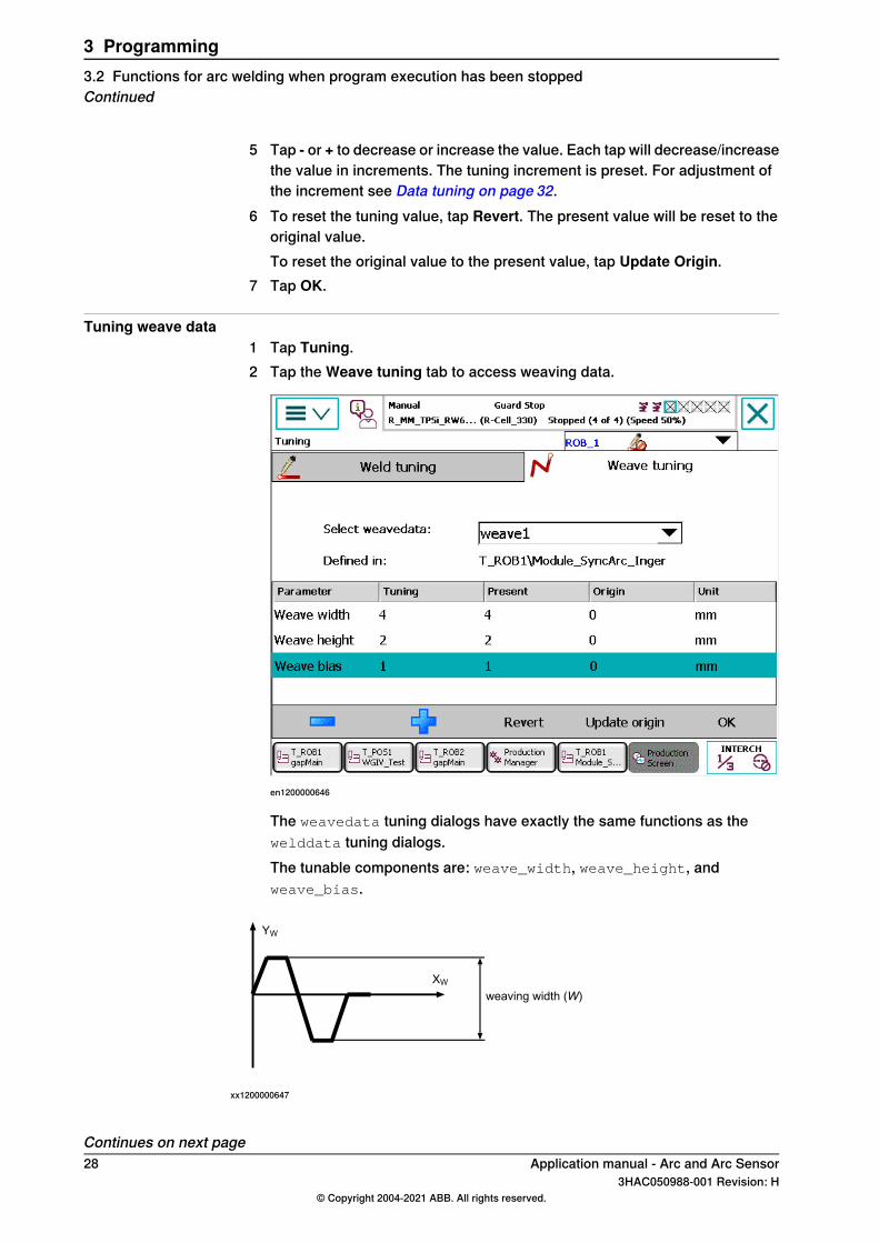
Tuning weave data1 Tap Tuning.2 Tap the Weave tuning tab to access weaving data.
en1200000646
The weavedata tuning dialogs have exactly the same functions as thewelddata tuning dialogs.The tunable components are: weave_width, weave_height, andweave_bias.
weaving width (W)
YW
XW
xx1200000647
Continues on next page28 Application manual - Arc and Arc Sensor
3HAC050988-001 Revision: H© Copyright 2004-2021 ABB. All rights reserved.
3 Programming3.2 Functions for arc welding when program execution has been stoppedContinued
weaving height (H)
YW
ZW
xx1200000648
weaving bias (B)
YW
XW
xx1200000649
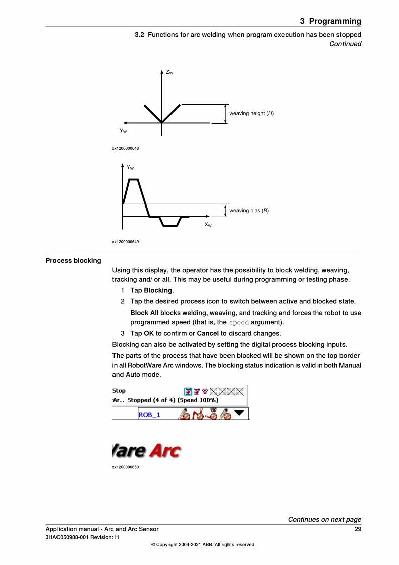
Process blockingUsing this display, the operator has the possibility to block welding, weaving,tracking and/ or all. This may be useful during programming or testing phase.
1 Tap Blocking.2 Tap the desired process icon to switch between active and blocked state.
Block All blocks welding, weaving, and tracking and forces the robot to useprogrammed speed (that is, the speed argument).
3 Tap OK to confirm or Cancel to discard changes.Blocking can also be activated by setting the digital process blocking inputs.The parts of the process that have been blocked will be shown on the top borderin all RobotWare Arc windows. The blocking status indication is valid in both Manualand Auto mode.
xx1200000650
Continues on next pageApplication manual - Arc and Arc Sensor 293HAC050988-001 Revision: H
© Copyright 2004-2021 ABB. All rights reserved.
3 Programming3.2 Functions for arc welding when program execution has been stopped
Continued
Blocking that is activated in the above dialog, is active only in the Manual operatingmode. It is, however, possible to allow blocking in Auto mode if the arc weldingsystem parameter auto inhib is On.
Note
If more than one system is configured in the robot, blocking from the dialog willaffect all systems. The digital process blocking inputs will only affect thecorresponding system.
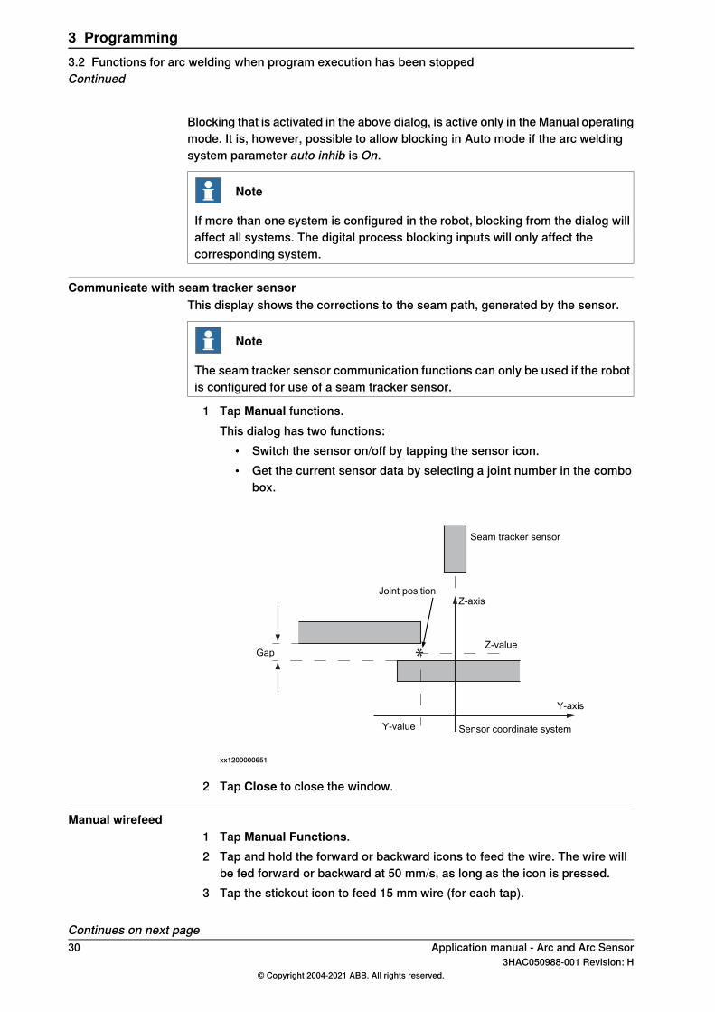
Communicate with seam tracker sensorThis display shows the corrections to the seam path, generated by the sensor.
Note
The seam tracker sensor communication functions can only be used if the robotis configured for use of a seam tracker sensor.
1 Tap Manual functions.This dialog has two functions:
• Switch the sensor on/off by tapping the sensor icon.• Get the current sensor data by selecting a joint number in the combo
box.
*
Seam tracker sensor
Sensor coordinate system
Y-axis
Z-axis
Z-value
Y-value
Gap
Joint position
xx1200000651
2 Tap Close to close the window.
Manual wirefeed1 Tap Manual Functions.2 Tap and hold the forward or backward icons to feed the wire. The wire will
be fed forward or backward at 50 mm/s, as long as the icon is pressed.3 Tap the stickout icon to feed 15 mm wire (for each tap).
Continues on next page30 Application manual - Arc and Arc Sensor
3HAC050988-001 Revision: H© Copyright 2004-2021 ABB. All rights reserved.
3 Programming3.2 Functions for arc welding when program execution has been stoppedContinued
4 Tap Close to close the window.
Note
If more than one system is configured in the robot, the dialog for selection of arcwelding systems can be used to select the corresponding wire feed equipment.
Manual gas purge1 Tap Manual Functions.2 Tap and hold the gas icon to purge gas.
The gas valve will be open as long as the icon is pressed.3 Tap Close to close the window.
Note
If more than one system is configured in the robot, the dialog for selection of arcwelding systems can be used to select the corresponding gas valve.
Select arc welding systemUp to three arc welding systems can exist at the same time in the robot.
1 Tap Settings.2 Tap a system in the section System settings to select a system.3 Tap OK to confirm.
If Cancel is tapped, the original arc welding system is retained as the currentsystem. When a system has been selected as the current system, all othermanual functions will operate on this system.
The selection of the arc welding system determines which equipment is activewhen manual operations, that is, Gas On, Manual Wirefeed are executed.
Changing tuning increments1 Tap Settings.2 In the section Tuning increments, tap a line to change the increment values.3 Change the value using the numerical keys.4 Tap OK to close the window and activate the chosen values.
Tapping Cancel discards the changes and closes the window.
Application manual - Arc and Arc Sensor 313HAC050988-001 Revision: H
© Copyright 2004-2021 ABB. All rights reserved.
3 Programming3.2 Functions for arc welding when program execution has been stopped
Continued
3.3 Functions for arc welding during program execution
GeneralArc welding functions during program execution:
• Weld data tuning• Weave data tuning• Measured value display
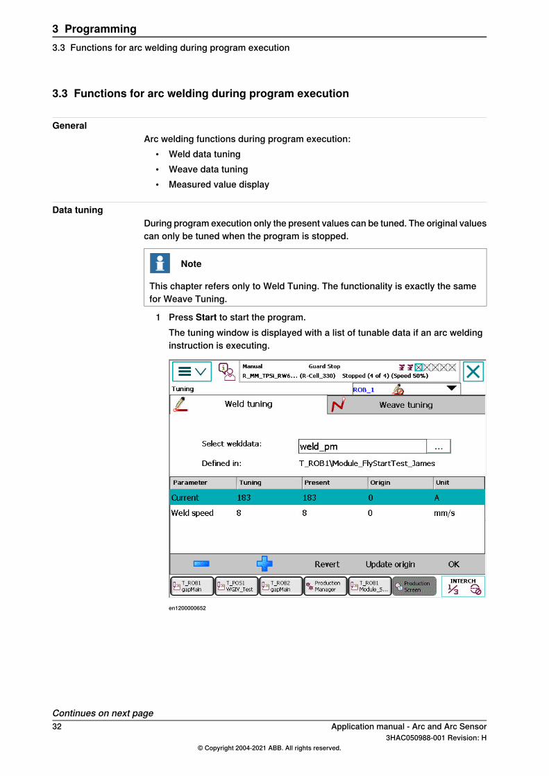
Data tuningDuring program execution only the present values can be tuned. The original valuescan only be tuned when the program is stopped.
Note
This chapter refers only to Weld Tuning. The functionality is exactly the samefor Weave Tuning.
1 Press Start to start the program.The tuning window is displayed with a list of tunable data if an arc weldinginstruction is executing.
en1200000652
Continues on next page32 Application manual - Arc and Arc Sensor
3HAC050988-001 Revision: H© Copyright 2004-2021 ABB. All rights reserved.
3 Programming3.3 Functions for arc welding during program execution
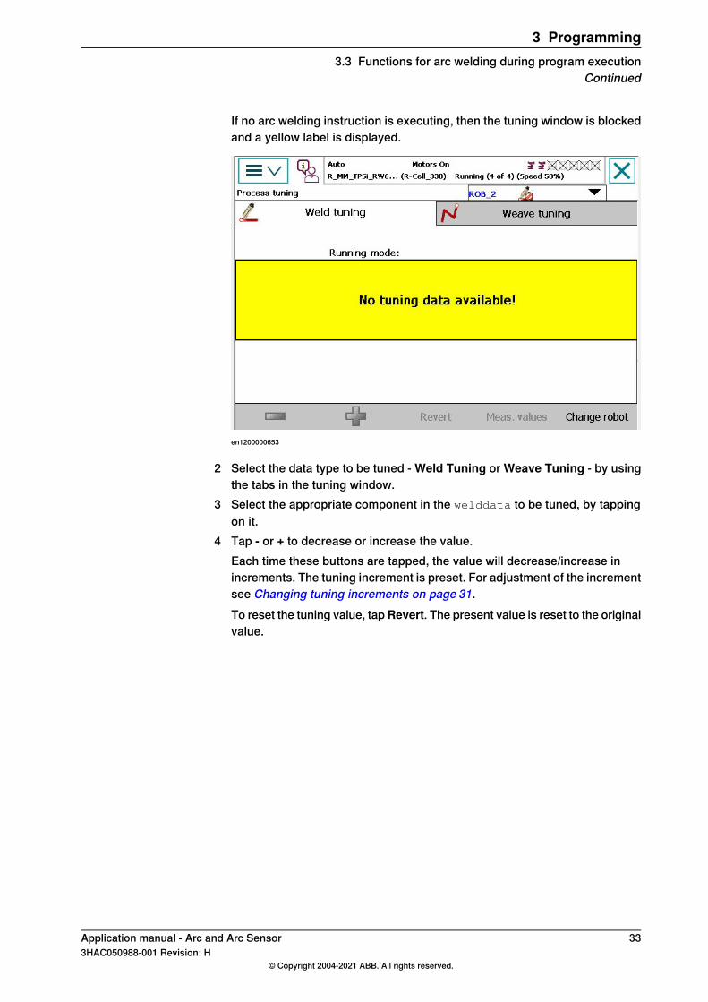
If no arc welding instruction is executing, then the tuning window is blockedand a yellow label is displayed.
en1200000653
2 Select the data type to be tuned - Weld Tuning or Weave Tuning - by usingthe tabs in the tuning window.
3 Select the appropriate component in the welddata to be tuned, by tappingon it.
4 Tap - or + to decrease or increase the value.Each time these buttons are tapped, the value will decrease/increase inincrements. The tuning increment is preset. For adjustment of the incrementsee Changing tuning increments on page 31.To reset the tuning value, tapRevert. The present value is reset to the originalvalue.
Application manual - Arc and Arc Sensor 333HAC050988-001 Revision: H
© Copyright 2004-2021 ABB. All rights reserved.
3 Programming3.3 Functions for arc welding during program execution
Continued

This page is intentionally left blank

4 ProgrammingRobotWare Arc systemswithMultiMove4.1 RobotWare Arc with MultiMove
IntroductionThe RobotWare Arc functionality for MultiMove systems is similar to the functionalityin single arc welding systems. Two or more welding robots are programmed inseparate tasks running independent or synchronized.The user interface provides the possibility to select an active welding robot for thefunctions to operate on.This chapter also describes how to install and configure an arc welding MultiMovesystem.
Application manual - Arc and Arc Sensor 353HAC050988-001 Revision: H
© Copyright 2004-2021 ABB. All rights reserved.
4 Programming RobotWare Arc systems with MultiMove4.1 RobotWare Arc with MultiMove
4.2 Functions for arc welding when program execution has been stopped
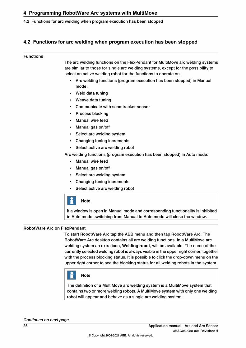
FunctionsThe arc welding functions on the FlexPendant for MultiMove arc welding systemsare similar to those for single arc welding systems, except for the possibility toselect an active welding robot for the functions to operate on.
• Arc welding functions (program execution has been stopped) in Manualmode:
• Weld data tuning• Weave data tuning• Communicate with seamtracker sensor• Process blocking• Manual wire feed• Manual gas on/off• Select arc welding system• Changing tuning increments• Select active arc welding robot
Arc welding functions (program execution has been stopped) in Auto mode:• Manual wire feed• Manual gas on/off• Select arc welding system• Changing tuning increments• Select active arc welding robot
Note
If a window is open in Manual mode and corresponding functionality is inhibitedin Auto mode, switching from Manual to Auto mode will close the window.
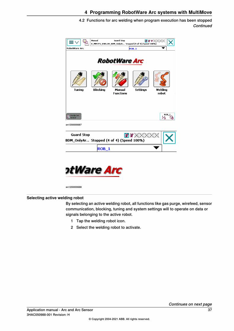
RobotWare Arc on FlexPendantTo start RobotWare Arc tap the ABB menu and then tap RobotWare Arc. TheRobotWare Arc desktop contains all arc welding functions. In a MultiMove arcwelding system an extra icon, Welding robot, will be available. The name of thecurrently selected welding robot is always visible in the upper right corner, togetherwith the process blocking status. It is possible to click the drop-down menu on theupper right corner to see the blocking status for all welding robots in the system.
Note
The definition of a MultiMove arc welding system is a MultiMove system thatcontains two or more welding robots. A MultiMove system with only one weldingrobot will appear and behave as a single arc welding system.
Continues on next page36 Application manual - Arc and Arc Sensor
3HAC050988-001 Revision: H© Copyright 2004-2021 ABB. All rights reserved.
4 Programming RobotWare Arc systems with MultiMove4.2 Functions for arc welding when program execution has been stopped
en1200000687
en1200000688
Selecting active welding robotBy selecting an active welding robot, all functions like gas purge, wirefeed, sensorcommunication, blocking, tuning and system settings will to operate on data orsignals belonging to the active robot.
1 Tap the welding robot icon.2 Select the welding robot to activate.
Continues on next pageApplication manual - Arc and Arc Sensor 373HAC050988-001 Revision: H
© Copyright 2004-2021 ABB. All rights reserved.
4 Programming RobotWare Arc systems with MultiMove4.2 Functions for arc welding when program execution has been stopped
Continued
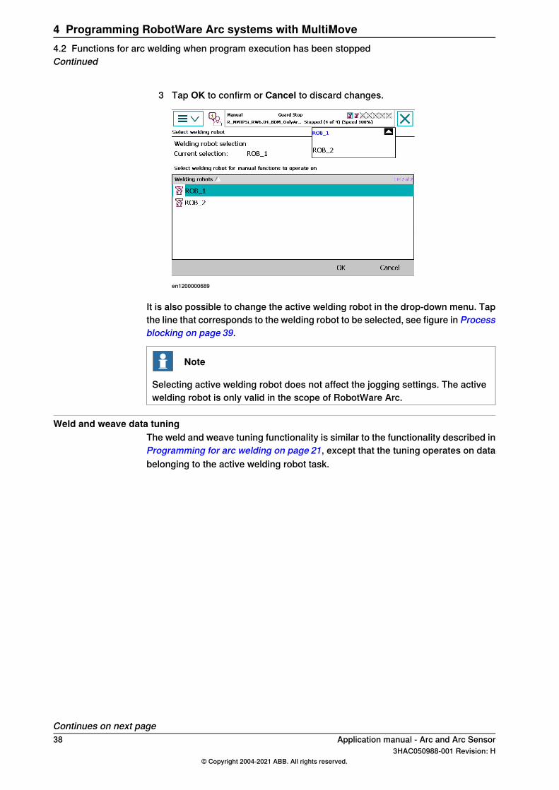
3 Tap OK to confirm or Cancel to discard changes.
en1200000689
It is also possible to change the active welding robot in the drop-down menu. Tapthe line that corresponds to the welding robot to be selected, see figure in Processblocking on page 39.
Note
Selecting active welding robot does not affect the jogging settings. The activewelding robot is only valid in the scope of RobotWare Arc.
Weld and weave data tuningThe weld and weave tuning functionality is similar to the functionality described inProgramming for arc welding on page 21, except that the tuning operates on databelonging to the active welding robot task.
Continues on next page38 Application manual - Arc and Arc Sensor
3HAC050988-001 Revision: H© Copyright 2004-2021 ABB. All rights reserved.
4 Programming RobotWare Arc systems with MultiMove4.2 Functions for arc welding when program execution has been stoppedContinued
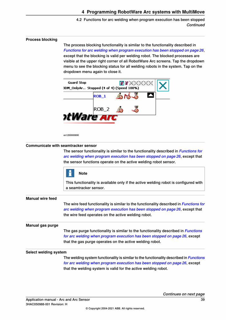
Process blockingThe process blocking functionality is similar to the functionality described inFunctions for arc welding when program execution has been stopped on page 26,except that the blocking is valid per welding robot. The blocked processes arevisible at the upper right corner of all RobotWare Arc screens. Tap the dropdownmenu to see the blocking status for all welding robots in the system. Tap on thedropdown menu again to close it.
en1200000690
Communicate with seamtracker sensorThe sensor functionality is similar to the functionality described in Functions forarc welding when program execution has been stopped on page 26, except thatthe sensor functions operate on the active welding robot sensor.
Note
This functionality is available only if the active welding robot is configured witha seamtracker sensor.
Manual wire feedThe wire feed functionality is similar to the functionality described in Functions forarc welding when program execution has been stopped on page 26, except thatthe wire feed operates on the active welding robot.
Manual gas purgeThe gas purge functionality is similar to the functionality described in Functionsfor arc welding when program execution has been stopped on page 26, exceptthat the gas purge operates on the active welding robot.
Select welding systemThe welding system functionality is similar to the functionality described in Functionsfor arc welding when program execution has been stopped on page 26, exceptthat the welding system is valid for the active welding robot.
Continues on next pageApplication manual - Arc and Arc Sensor 393HAC050988-001 Revision: H
© Copyright 2004-2021 ABB. All rights reserved.
4 Programming RobotWare Arc systems with MultiMove4.2 Functions for arc welding when program execution has been stopped
Continued

Changing tuning incrementsThe tuning increment functionality is similar to the functionality described inFunctions for arc welding when program execution has been stopped on page 26,except that the increments are valid for the active welding robot.
40 Application manual - Arc and Arc Sensor3HAC050988-001 Revision: H
© Copyright 2004-2021 ABB. All rights reserved.
4 Programming RobotWare Arc systems with MultiMove4.2 Functions for arc welding when program execution has been stoppedContinued
4.3 Functions for arc welding during program execution
FunctionsArc welding functions during program execution:
• Weld data tuning• Weave data tuning• Measured value display• Selecting active welding robot
Data tuningThe data tuning functionality is similar to the functionality described in Functionsfor arc welding during program execution on page 32, except that the tuningoperates on data belonging to the active welding robot task.
Measurement valuesThe measurement values functionality is similar to the functionality described inFunctions for arc welding during program execution on page 32, except that thevalues displayed belongs to the active welding robot.
Selecting active welding robotIt is possible to change active welding robot during program execution.
1 Tap Change robot.2 Select active welding robot.3 Tap OK to confirm or Cancel to discard changes.
The weld and weave data tuning will now operate on data belonging to the activewelding robot.
Application manual - Arc and Arc Sensor 413HAC050988-001 Revision: H
© Copyright 2004-2021 ABB. All rights reserved.
4 Programming RobotWare Arc systems with MultiMove4.3 Functions for arc welding during program execution
4.4 Configuration
IntroductionIn a MultiMove system, the configuration parameter MotionTimeout is of greatimportance, especially when running in synchronized mode. The parameter shouldhave a non-zero value to be able to shut down process equipment when one ofthe robots does not start the intended motion after a certain time frame.
ExampleThe robots ROB1 and ROB2 are both welding in synchronized mode. TheMotionTimeout parameter is set to 1s. Since they are running in synchronizedmode, both of the robots TCP should arrive at the starting position of the weld atthe same time. Both robots strike the arc at the same time. ROB1 gets the Arc OKsignal, the robot is ready to start the motion, the motion timer starts to tick. ROB2has a problem to ignite properly. That means that during this period ROB1 isstanding still with the arc on. The motion timeout will cause an error after 1 secondin ROB1. Then the error ERR_PATH_STOP will be distributed to the other motiontasks to react on. This parameter is used to avoid that one of the robots is standingstill with the arc ignited and burning through the material.
Note
When running in synchronized mode, the motion timeout must not be lower thanthe ignition timeout value. There is otherwise a risk that the motion timer willexpire before the ignition timer. Since the motion timeout error is non recoverable,it will hide the real error, arc ignition timeout. The recommendation is to set theignition timeout value some milliseconds shorter than the movement timeoutvalue, 0.05 seconds is sufficient.
Error handlingError handling in a MultiMove setup (running synchronized) requires that the errorhandlers are the same in all robot tasks. That is due to the fact that if there is anerror in one robot, the other robots will also end up in their local error handler.
Example 1Automatic retries directly after an error.If no_of_retries is set to a value other than 0, automatic retries will be performedby RobotWare Arc until no_of_retries has expired. Then the user error handler willbe executed.If the error handler has the following contents, it will be executed until the error isfixed or the SYS domain parameter -NoOfRetry has expired.
MoveJ p1, v1000, fine, Rob2_tool\WObj:=wobj_STN1;
ArcLStart p2, v1000, sm1, wd1_ind\Weave:=wv0, fine,Rob2_tool\WObj:=wobj_STN1;
ArcLEnd p6, v1000, sm1, wd1_ind\Weave:=wv0, fine,Rob2_tool\WObj:=wobj_STN1;
ERROR
StorePath;
Continues on next page42 Application manual - Arc and Arc Sensor
3HAC050988-001 Revision: H© Copyright 2004-2021 ABB. All rights reserved.
4 Programming RobotWare Arc systems with MultiMove4.4 Configuration
RestoPath;
StartMoveRetry;
Example 2Automatic retry after cleaning the welding torch.The following is an example of an error handler with the possibility to move to aservice position in the failing robot, clean the welding gun, go back to the errorlocation and start welding again. The other robots will wait for the failing robot toget ready and they will all restart the synchronized motion again when the failingrobot executes StartMoveRetry.
VAR robtarget errPos1;
VAR tooldata tErr;
VAR wobjdata obErr;
MoveJ p1, v1000, fine, Rob2_tool\WObj:=wobj_STN1;
ArcLStart p2, v1000, sm1, wd1_ind\Weave:=wv0, fine,Rob2_tool\WObj:=wobj_STN1;
ArcLEnd p6, v1000, sm1, wd1_ind\Weave:=wv0, fine,Rob2_tool\WObj:=wobj_STN1;
ERROR
IF ERRNO=AW_WELD_ERR THEN
StorePath;
errPos1:=CRobT(\Tool:=tErr\WObj:=obErr);
MoveL RelTool(errPos1,0,0,-20),v100,fine,tErr\WObj:=obErr;
TPWrite "Cleaning...";
WaitTime 1;
MoveL errPos1,v100,fine,tErr\WObj:=obErr;
RestoPath;
ELSE
StorePath;
RestoPath;
ENDIF
StartMove;
RETRY;
Example 3The following example shows error handling with the possibility to jog away fromthe path at an error, press start and the welding will resume. Here this is done onlyat a wire stick error, otherwise automatic cleaning is performed.
VAR robtarget errPos1;
VAR tooldata tErr;
VAR wobjdata obErr;
MoveJ p1, v1000, fine, Rob2_tool\WObj:=wobj_STN1;
ArcLStart p2, v1000, sm1, wd1_ind\Weave:=wv0, fine,Rob2_tool\WObj:=wobj_STN1;
ArcLEnd p6, v1000, sm1, wd1_ind\Weave:=wv0, fine,Rob2_tool\WObj:=wobj_STN1;
ERROR
IF ERRNO=AW_WIRE_ERR THEN StorePath;
TPWrite "This error is caused by wire stuck";
TPWrite "Cut the wire and press start !";
Stop;
Continues on next pageApplication manual - Arc and Arc Sensor 433HAC050988-001 Revision: H
© Copyright 2004-2021 ABB. All rights reserved.
4 Programming RobotWare Arc systems with MultiMove4.4 Configuration
Continued
RestoPath;
StartMove;
RETRY;
ENDIF
IF ERRNO=AW_WELD_ERR THEN
! Automatic move to cleaning position
! Move back to error position and start welding again.
StorePath;
errPos1:=CRobT(\Tool:=tErr);
MoveL RelTool(errPos1,0,0,-50),v10,fine,tErr;
TPWrite "Cleaning...";
WaitTime 1;
MoveL errPos1,v10,fine,tErr;
RestoPath;
StartMove;
RETRY;
ENDIF
Instructions in non-welding robotProgramming RobotWare Arc in synchronized mode with instruction id’s requiressome special considerations for the error handling to work correctly. In thenon-welding robot or additional axis, some new instructions must be used whenthere are corresponding weld instructions in the welding robots.The instructions should be used to ensure that the automatic retry functionalityworks correctly and that the error levels are the same in all motion tasks.
Example 1FlexPositioner (ArcMoveJ instead of MoveJ)
T_ROB1 (non-welding robot):
ArcMoveJ p2 \ID:=101, v1000, z1, tSvetsbord;
T_ROB2:
ArcL p2 \ID:=101, v1000, sm1, wd2, wv1,z1,wGun_ROB2\WObj:=WOBJ_ROB1;
T_ROB3:
ArcL p2 \ID:=101, v1000, sm1, wd2, wv1, z1,wGun_ROB3\WObj:=WOBJ_ROB1;
Example 2TwinArc (ArcMoveExtJ instead of MoveExtJ)
STN1 (additional axis):
ArcMoveExtJ p2 \ID:=101, v1000, z1;
T_ROB1:
ArcL p2 \ID:=101, v1000, sm1, wd2, wv1, z1,wGun_ROB1\WObj:=WOBJ_STN1;
T_ROB2:
ArcL p2 \ID:=101, v1000, sm1, wd2, wv1, z1,wGun_ROB2\WObj:=WOBJ_STN1;
Continues on next page44 Application manual - Arc and Arc Sensor
3HAC050988-001 Revision: H© Copyright 2004-2021 ABB. All rights reserved.
4 Programming RobotWare Arc systems with MultiMove4.4 ConfigurationContinued
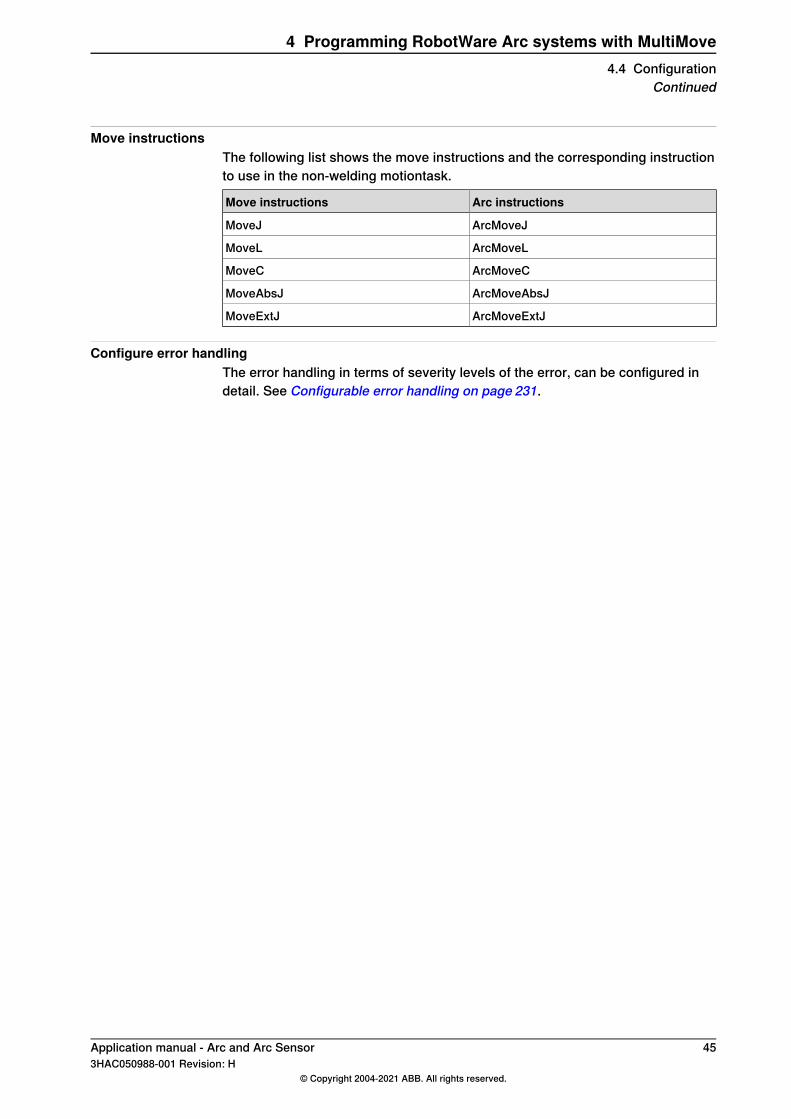
Move instructionsThe following list shows the move instructions and the corresponding instructionto use in the non-welding motiontask.
Arc instructionsMove instructions
ArcMoveJMoveJ
ArcMoveLMoveL
ArcMoveCMoveC
ArcMoveAbsJMoveAbsJ
ArcMoveExtJMoveExtJ
Configure error handlingThe error handling in terms of severity levels of the error, can be configured indetail. See Configurable error handling on page 231.
Application manual - Arc and Arc Sensor 453HAC050988-001 Revision: H
© Copyright 2004-2021 ABB. All rights reserved.
4 Programming RobotWare Arc systems with MultiMove4.4 Configuration
Continued
4.5 Limitations
Restart distanceIt is not possible to have different restart distances if running synchronized motions.Since it is not possible to determine which robot that controls the restart distancein this case, the recommendation is to have the same parameter values in eachrobot.
Use of finepointFinepoint must be used in the arc welding instruction before:
• SyncMoveOn• SyncMoveOff• WaitSyncTask
Error handlingIf an error handler is present, but it does not handle the error, that is none of theinstructions RETRY, TRYNEXT, RETURN, or RAISE are present in the error handler,then the active motion path is cleared. That means, that neither regain to path norbacking on the path is possible. The robot movement starts from the current positionof the TCP, which might result in a path shortcut.
RaiseToUser problemIf ArcL/ArcC instructions are encapsulated by NOSTEPIN/NOVIEW routines, theERROR handler of this NOSTEPIN/NOVIEW routine is ignored for the followingrecoverable errors:
• AW_START_ERR• AW_IGNI_ERR• AW_WELD_ERR• AW_EQIP_ERR• AW_WIRE_ERR• AW_STOP_ERR• AW_TRACK_ERR• AW_TRACKSTA_ERR• AW_TRACKCORR_ERR• AW_USERSIG_ERR• ERR_PATH_STOP
The system looks for error handlers to be run, starting with the first STEPIN routinefound in the RAPID call chain.
ExampleMODULE MY_PROG
PROC main ()
MyArcL;
ERROR
TPWrite "main error handler";
Continues on next page46 Application manual - Arc and Arc Sensor
3HAC050988-001 Revision: H© Copyright 2004-2021 ABB. All rights reserved.
4 Programming RobotWare Arc systems with MultiMove4.5 Limitations
ENDPROC
ENDMODULE
MODULE MY_ARC (SYSMODULE, NOVIEW)
PROC MyArcL ()
ArcL;
ERROR
TPWrite "MyArcL error handler!";
ENDPROC
ENDMODULE
If an error occurs in ArcL, the error handler of MyArcL is NOT executed (becauseMyArcL is part of a NOSTEPIN/NOVIEW module), but the error handler of main isexecuted.
Missing instructions in additional axisIf MultiMove cells are configured and setup with an additional axis or positioner,without any external option from ABB of the type ABB ATRM/AW System Disk,then the awBase.sys RAPID module must be installed in that task.If this is not done, it will not be possible to select any of the following non-weldingarc instructions from the pick list on the FlexPendant.
• ArcMoveExtJ• ArcMoveAbsJ• ArcMoveL• ArcMoveC• ArcMoveJ
These must be used to have proper error handling when using RobotWare Arc inMultiMove. The installation of the module is done by adding the following to SYS.cfg,where task name represents the name of the additional axis RAPID task name.
CAB_TASK_MODULES:
#
-File RELEASE:/options/arc/ArcBase/code/awBase.sys
-ModName "awBase" -Install -Task "taskname"
Application manual - Arc and Arc Sensor 473HAC050988-001 Revision: H
© Copyright 2004-2021 ABB. All rights reserved.
4 Programming RobotWare Arc systems with MultiMove4.5 Limitations
Continued

This page is intentionally left blank
5 Weld Error Recovery5.1 Weld Error Recovery and error handling
Weld Error RecoveryDuring robot production process errors sometimes arise causing the robot to stop.The Weld Error Recovery feature provides several different solutions for processerror recovery, which allows operators to automatically move the robot out of theerror location to a service position. After the process error is corrected the robotautomatically returns back to the error location and continues production. This willhelp minimizing production downtime.Since the creation of safe collision free escape paths for error handling often ismore time consuming than the creation of the actual production program, errorhandling under program control is rarely utilized. That is why the Weld ErrorRecovery feature is always included with RobotWare Arc, and the basic errorrecovery features are available without any additional programming. This includesFlexPendant screens to provide standard error recovery support for the weldingprocess.Advanced features such as the ability to escape to a service location, requireadditional programming on the part of the user. The Weld Error Recovery featurewill store position information during execution of the production program, utilizinga built-in Path Recorder. When an error occurs the stored sequence of positiondata is traversed backwards extracting the robot from the work piece. Thus, thepath recorder eliminates any need for additional programming of escape paths.
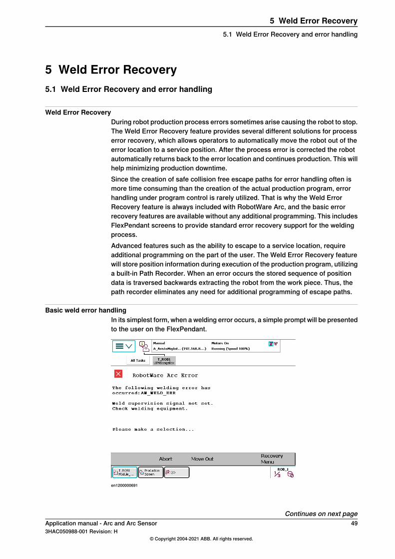
Basic weld error handlingIn its simplest form, when a welding error occurs, a simple prompt will be presentedto the user on the FlexPendant.
en1200000691
Continues on next pageApplication manual - Arc and Arc Sensor 493HAC050988-001 Revision: H
© Copyright 2004-2021 ABB. All rights reserved.
5 Weld Error Recovery5.1 Weld Error Recovery and error handling
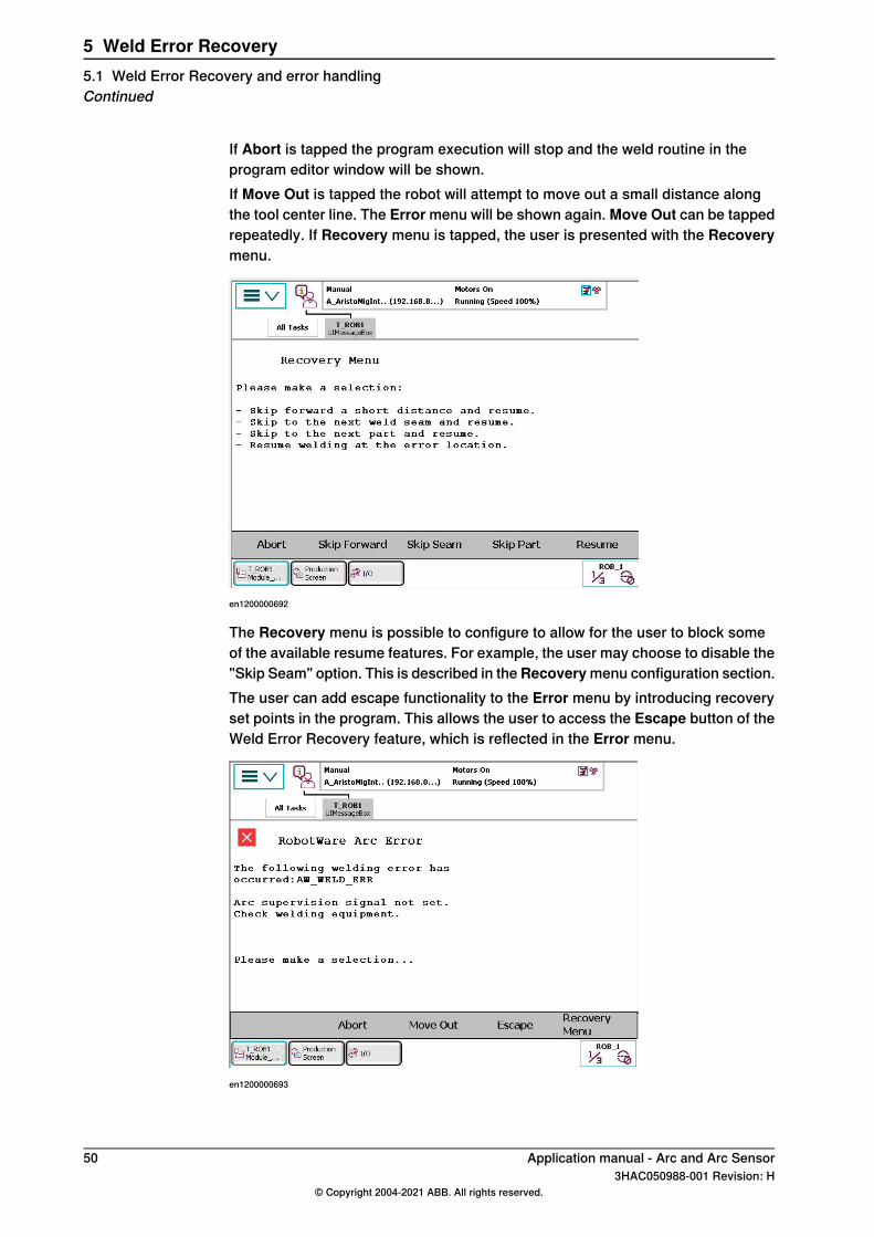
If Abort is tapped the program execution will stop and the weld routine in theprogram editor window will be shown.If Move Out is tapped the robot will attempt to move out a small distance alongthe tool center line. The Error menu will be shown again. Move Out can be tappedrepeatedly. If Recovery menu is tapped, the user is presented with the Recoverymenu.
en1200000692
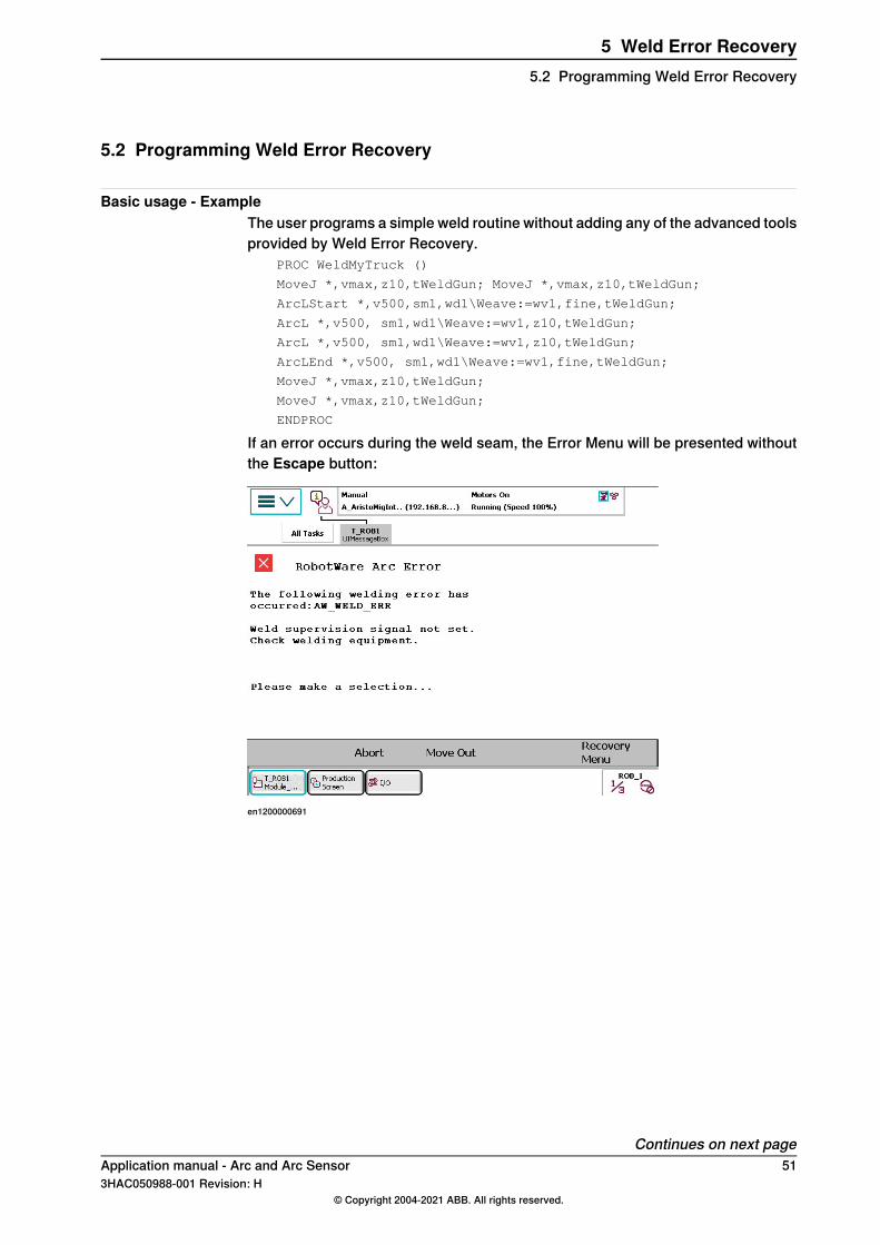
The Recovery menu is possible to configure to allow for the user to block someof the available resume features. For example, the user may choose to disable the"Skip Seam" option. This is described in theRecoverymenu configuration section.The user can add escape functionality to the Error menu by introducing recoveryset points in the program. This allows the user to access the Escape button of theWeld Error Recovery feature, which is reflected in the Error menu.
en1200000693
50 Application manual - Arc and Arc Sensor3HAC050988-001 Revision: H
© Copyright 2004-2021 ABB. All rights reserved.
5 Weld Error Recovery5.1 Weld Error Recovery and error handlingContinued
5.2 Programming Weld Error Recovery
Basic usage - ExampleThe user programs a simple weld routine without adding any of the advanced toolsprovided by Weld Error Recovery.
PROC WeldMyTruck ()
MoveJ *,vmax,z10,tWeldGun; MoveJ *,vmax,z10,tWeldGun;
ArcLStart *,v500,sm1,wd1\Weave:=wv1,fine,tWeldGun;
ArcL *,v500, sm1,wd1\Weave:=wv1,z10,tWeldGun;
ArcL *,v500, sm1,wd1\Weave:=wv1,z10,tWeldGun;
ArcLEnd *,v500, sm1,wd1\Weave:=wv1,fine,tWeldGun;
MoveJ *,vmax,z10,tWeldGun;
MoveJ *,vmax,z10,tWeldGun;
ENDPROC
If an error occurs during the weld seam, the Error Menu will be presented withoutthe Escape button:
en1200000691
Continues on next pageApplication manual - Arc and Arc Sensor 513HAC050988-001 Revision: H
© Copyright 2004-2021 ABB. All rights reserved.
5 Weld Error Recovery5.2 Programming Weld Error Recovery
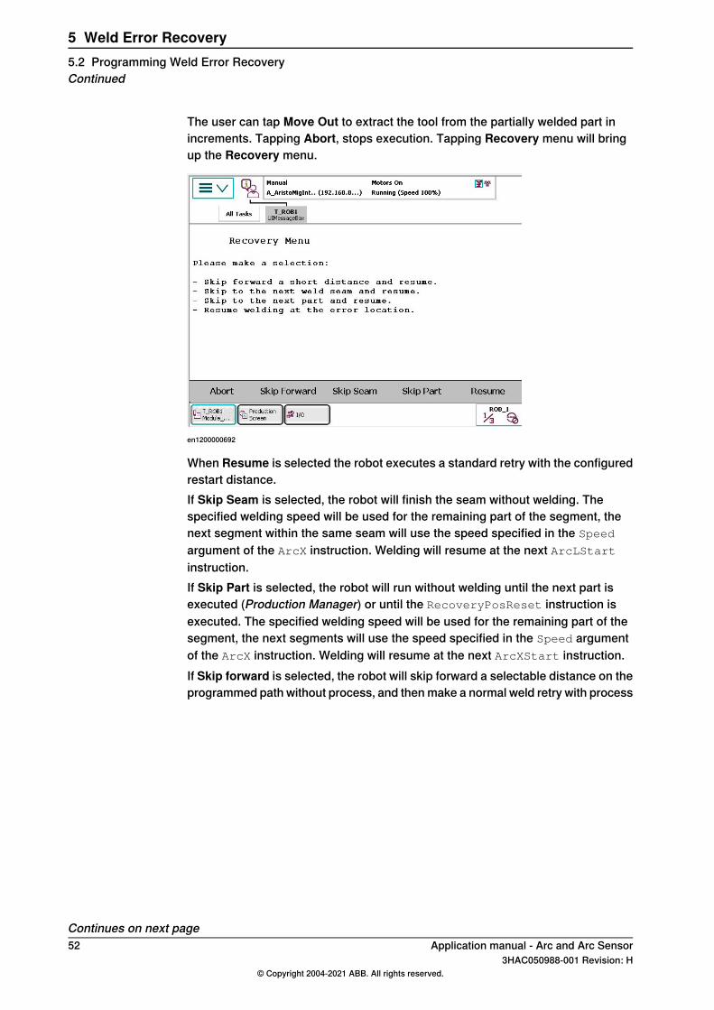
The user can tap Move Out to extract the tool from the partially welded part inincrements. Tapping Abort, stops execution. Tapping Recovery menu will bringup the Recovery menu.
en1200000692
When Resume is selected the robot executes a standard retry with the configuredrestart distance.If Skip Seam is selected, the robot will finish the seam without welding. Thespecified welding speed will be used for the remaining part of the segment, thenext segment within the same seam will use the speed specified in the Speed
argument of the ArcX instruction. Welding will resume at the next ArcLStartinstruction.If Skip Part is selected, the robot will run without welding until the next part isexecuted (Production Manager) or until the RecoveryPosReset instruction isexecuted. The specified welding speed will be used for the remaining part of thesegment, the next segments will use the speed specified in the Speed argumentof the ArcX instruction. Welding will resume at the next ArcXStart instruction.If Skip forward is selected, the robot will skip forward a selectable distance on theprogrammed path without process, and then make a normal weld retry with process
Continues on next page52 Application manual - Arc and Arc Sensor
3HAC050988-001 Revision: H© Copyright 2004-2021 ABB. All rights reserved.
5 Weld Error Recovery5.2 Programming Weld Error RecoveryContinued
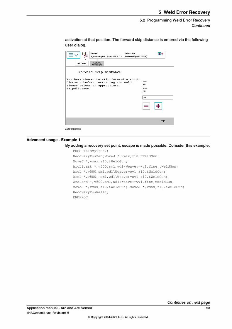
activation at that position. The forward skip distance is entered via the followinguser dialog.
en1200000695
Advanced usage - Example 1By adding a recovery set point, escape is made possible. Consider this example:
PROC WeldMyTruck)
RecoveryPosSet;MoveJ *,vmax,z10,tWeldGun;
MoveJ *,vmax,z10,tWeldGun;
ArcLStart *,v500,sm1,wd1\Weave:=wv1,fine,tWeldGun;
ArcL *,v500,sm1,wd1\Weave:=wv1,z10,tWeldGun;
ArcL *,v500, sm1,wd1\Weave:=wv1,z10,tWeldGun;
ArcLEnd *,v500,sm1,wd1\Weave:=wv1,fine,tWeldGun;
MoveJ *,vmax,z10,tWeldGun; MoveJ *,vmax,z10,tWeldGun;
RecoveryPosReset;
ENDPROC
Continues on next pageApplication manual - Arc and Arc Sensor 533HAC050988-001 Revision: H
© Copyright 2004-2021 ABB. All rights reserved.
5 Weld Error Recovery5.2 Programming Weld Error Recovery
Continued
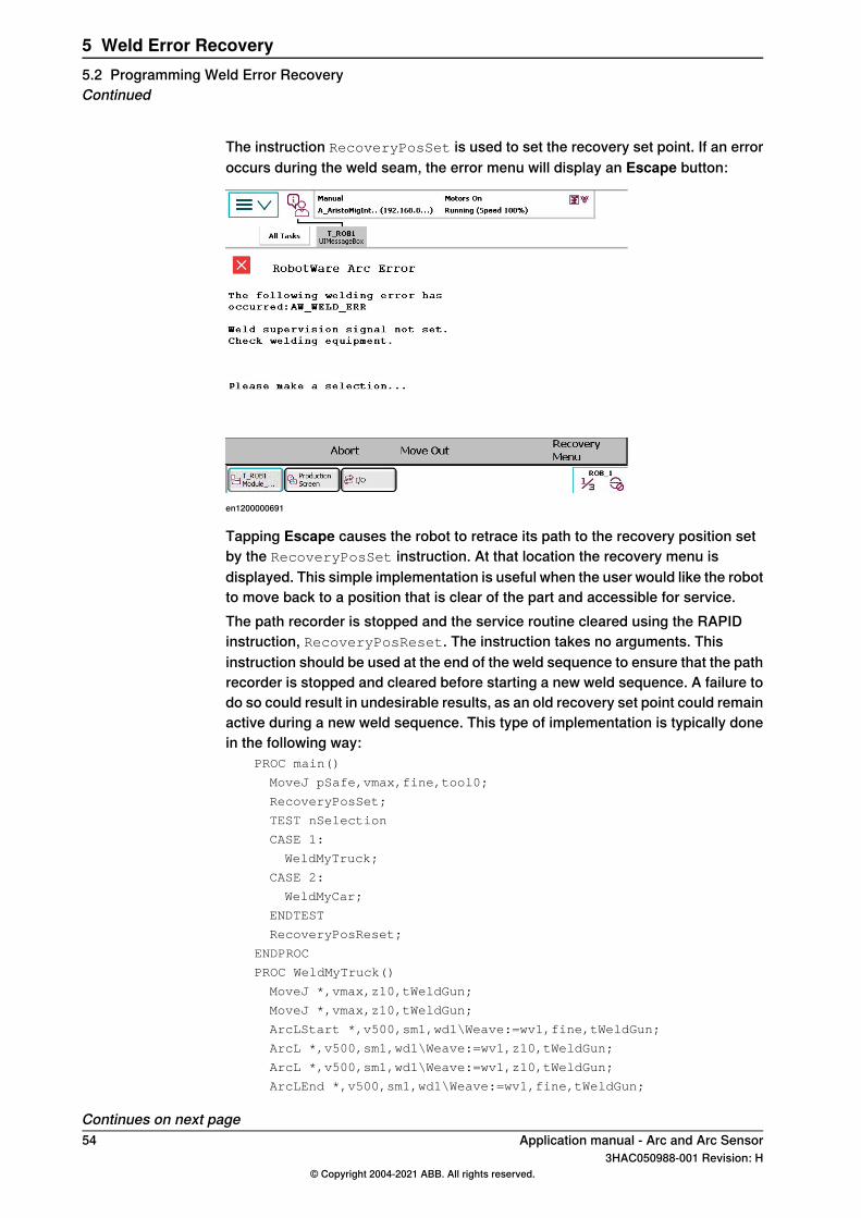
The instruction RecoveryPosSet is used to set the recovery set point. If an erroroccurs during the weld seam, the error menu will display an Escape button:
en1200000691
Tapping Escape causes the robot to retrace its path to the recovery position setby the RecoveryPosSet instruction. At that location the recovery menu isdisplayed. This simple implementation is useful when the user would like the robotto move back to a position that is clear of the part and accessible for service.The path recorder is stopped and the service routine cleared using the RAPIDinstruction, RecoveryPosReset. The instruction takes no arguments. Thisinstruction should be used at the end of the weld sequence to ensure that the pathrecorder is stopped and cleared before starting a new weld sequence. A failure todo so could result in undesirable results, as an old recovery set point could remainactive during a new weld sequence. This type of implementation is typically donein the following way:
PROC main()
MoveJ pSafe,vmax,fine,tool0;
RecoveryPosSet;
TEST nSelection
CASE 1:
WeldMyTruck;
CASE 2:
WeldMyCar;
ENDTEST
RecoveryPosReset;
ENDPROC
PROC WeldMyTruck()
MoveJ *,vmax,z10,tWeldGun;
MoveJ *,vmax,z10,tWeldGun;
ArcLStart *,v500,sm1,wd1\Weave:=wv1,fine,tWeldGun;
ArcL *,v500,sm1,wd1\Weave:=wv1,z10,tWeldGun;
ArcL *,v500,sm1,wd1\Weave:=wv1,z10,tWeldGun;
ArcLEnd *,v500,sm1,wd1\Weave:=wv1,fine,tWeldGun;
Continues on next page54 Application manual - Arc and Arc Sensor
3HAC050988-001 Revision: H© Copyright 2004-2021 ABB. All rights reserved.
5 Weld Error Recovery5.2 Programming Weld Error RecoveryContinued
MoveJ *,vmax,z10,tWeldGun;
MoveJ *,vmax,z10,tWeldGun;
ENDPROC
This type of implementation also provides escape behavior for multiple partprocedures shown in the test case logic above.
Advanced usage - Example 2Recovery positions may be set at any point in a weld sequence. In some cases itmay be necessary to have an alternate recovery position that is set mid-weld. Thisis perfectly ok.
PROC WeldMyCar()
RecoveryPosSet;
MoveJ *,vmax,z10,tWeldGun;
MoveJ *,vmax,z10,tWeldGun;
ArcLStart *,v500,sm1,wd1\Weave:=wv1,fine,tWeldGun;
ArcL *,v500,sm1,wd1\Weave:=wv1,z10,tWeldGun;
SetDO doClamp,high;
RecoveryPosSet;
ArcL *,v500,sm1,wd1\Weave:=wv1,z10,tWeldGun;
ArcLEnd *,v500,sm1,wd1\Weave:=wv1,fine,tWeldGun;
MoveJ *,vmax,z10,tWeldGun;
MoveJ *,vmax,z10,tWeldGun;
RecoveryPosReset;
ENDPROC
An implementation like this is useful if the robot is not permitted to move backwardpast the SetDO instruction.
Advanced usage - Example 3Using the service routine feature will extend the Weld Error Recovery escapefunctionality. The service routine is a user-defined procedure that is launched afterthe robot retraces a recorded path back to a recovery position. The routine maybe used to move the robot from the recovery position to a service location, or anyother behavior that can be implemented in RAPID. Consider the following example:
PROC main()MoveJ pSafe,vmax,fine,tool0;
RecoveryPosSet\ServRoutine:="ServiceRoutine";
TEST nSelect
CASE 1:
WeldMyTruck;
CASE 2:
WeldMyCar;
ENDTEST
RecoveryPosReset;
ENDPROC
PROC WeldMyTruck ()
MoveJ *,vmax,z10,tWeldGun;
MoveJ *,vmax,z10,tWeldGun;
ArcLStart *,v500,sm1,wd1\Weave:=wv1,fine,tWeldGun;
ArcL *,v500,sm1,wd1\Weave:=wv1,z10,tWeldGun;
ArcL *,v500,sm1,wd1\Weave:=wv1,z10,tWeldGun;
Continues on next pageApplication manual - Arc and Arc Sensor 553HAC050988-001 Revision: H
© Copyright 2004-2021 ABB. All rights reserved.
5 Weld Error Recovery5.2 Programming Weld Error Recovery
Continued
ArcLEnd *,v500,sm1,wd1\Weave:=wv1,fine,tWeldGun;
MoveJ *,vmax,z10,tWeldGun;
MoveJ *,vmax,z10,tWeldGun;
ENDPROC
PROC ServiceRoutine()
MoveJ *,vmax,z10,tool0;
MoveJ *,vmax,z10,tool0;
MoveL pService,vmax,z10,tool0;
RecoveryMenu;
MoveL *,vmax,z10,tool0;
MoveJ *,vmax,z10,tool0;
MoveJ pSafe,vmax,z10,tool0;
ENDPROC
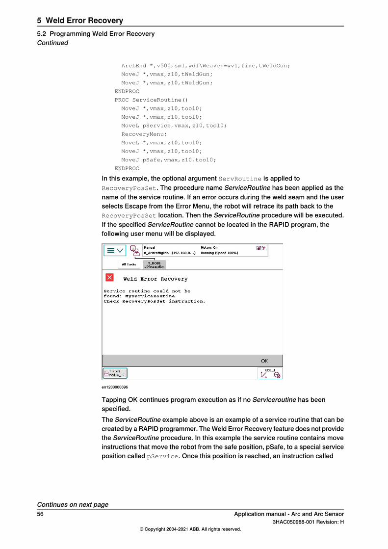
In this example, the optional argument ServRoutine is applied toRecoveryPosSet. The procedure name ServiceRoutine has been applied as thename of the service routine. If an error occurs during the weld seam and the userselects Escape from the Error Menu, the robot will retrace its path back to theRecoveryPosSet location. Then the ServiceRoutine procedure will be executed.If the specified ServiceRoutine cannot be located in the RAPID program, thefollowing user menu will be displayed.
en1200000696
Tapping OK continues program execution as if no Serviceroutine has beenspecified.The ServiceRoutine example above is an example of a service routine that can becreated by a RAPID programmer. The Weld Error Recovery feature does not providethe ServiceRoutine procedure. In this example the service routine contains moveinstructions that move the robot from the safe position, pSafe, to a special serviceposition called pService. Once this position is reached, an instruction called
Continues on next page56 Application manual - Arc and Arc Sensor
3HAC050988-001 Revision: H© Copyright 2004-2021 ABB. All rights reserved.
5 Weld Error Recovery5.2 Programming Weld Error RecoveryContinued
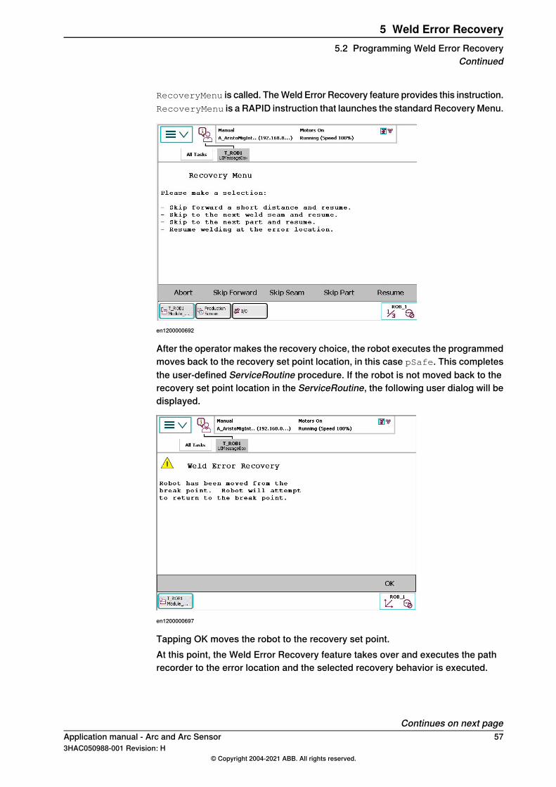
RecoveryMenu is called. The Weld Error Recovery feature provides this instruction.RecoveryMenu is a RAPID instruction that launches the standard Recovery Menu.
en1200000692
After the operator makes the recovery choice, the robot executes the programmedmoves back to the recovery set point location, in this case pSafe. This completesthe user-defined ServiceRoutine procedure. If the robot is not moved back to therecovery set point location in the ServiceRoutine, the following user dialog will bedisplayed.
en1200000697
Tapping OK moves the robot to the recovery set point.At this point, the Weld Error Recovery feature takes over and executes the pathrecorder to the error location and the selected recovery behavior is executed.
Continues on next pageApplication manual - Arc and Arc Sensor 573HAC050988-001 Revision: H
© Copyright 2004-2021 ABB. All rights reserved.
5 Weld Error Recovery5.2 Programming Weld Error Recovery
Continued
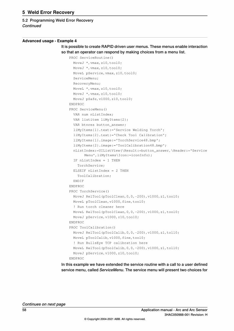
Advanced usage - Example 4It is possible to create RAPID driven user menus. These menus enable interactionso that an operator can respond by making choices from a menu list.
PROC ServiceRoutine()
MoveJ *,vmax,z10,tool0;
MoveJ *,vmax,z10,tool0;
MoveL pService,vmax,z10,tool0;
ServiceMenu;
RecoveryMenu;
MoveL *,vmax,z10,tool0;
MoveJ *,vmax,z10,tool0;
MoveJ pSafe,v1000,z10,tool0;
ENDPROC
PROC ServiceMenu()
VAR num nListIndex;
VAR listitem liMyItems{2};
VAR btnres button_answer;
liMyItems{1}.text:="Service Welding Torch";
liMyItems{2}.text:="Check Tool Calibration";
liMyItems{1}.image:="TorchService48.bmp";
liMyItems{2}.image:="ToolCalibration48.bmp";
nListIndex:=UIListView(\Result:=button_answer,\Header:="ServiceMenu",liMyItems\Icon:=iconInfo);
IF nListIndex = 1 THEN
TorchService;
ELSEIF nListIndex = 2 THEN
ToolCalibration;
ENDIF
ENDPROC
PROC TorchService()
MoveJ RelTool(pToolClean,0,0,-200),v1000,z1,tool0;
MoveL pToolClean,v1000,fine,tool0;
! Run torch cleaner here
MoveL RelTool(pToolClean,0,0,-200),v1000,z1,tool0;
MoveJ pService,v1000,z10,tool0;
ENDPROC
PROC ToolCalibration()
MoveJ RelTool(pToolCalib,0,0,-200),v1000,z1,toll0;
MoveL pToolCalib,v1000,fine,tool0;
! Run BullsEye TCP calibration here
MoveL RelTool(pToolCalib,0,0,-200),v1000,z1,toll0;
MoveJ pService,v1000,z10,tool0;
ENDPROC
In this example we have extended the service routine with a call to a user definedservice menu, called ServiceMenu. The service menu will present two choices for
Continues on next page58 Application manual - Arc and Arc Sensor
3HAC050988-001 Revision: H© Copyright 2004-2021 ABB. All rights reserved.
5 Weld Error Recovery5.2 Programming Weld Error RecoveryContinued
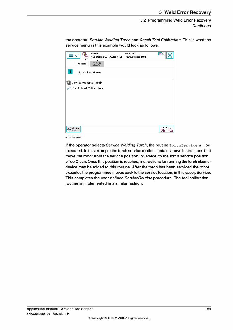
the operator, Service Welding Torch and Check Tool Calibration. This is what theservice menu in this example would look as follows.
en1200000698
If the operator selects Service Welding Torch, the routine TorchService will beexecuted. In this example the torch service routine contains move instructions thatmove the robot from the service position, pService, to the torch service position,pToolClean. Once this position is reached, instructions for running the torch cleanerdevice may be added to this routine. After the torch has been serviced the robotexecutes the programmed moves back to the service location, in this case pService.This completes the user-defined ServiceRoutine procedure. The tool calibrationroutine is implemented in a similar fashion.
Application manual - Arc and Arc Sensor 593HAC050988-001 Revision: H
© Copyright 2004-2021 ABB. All rights reserved.
5 Weld Error Recovery5.2 Programming Weld Error Recovery
Continued
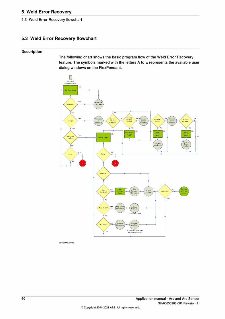
5.3 Weld Error Recovery flowchart
DescriptionThe following chart shows the basic program flow of the Weld Error Recoveryfeature. The symbols marked with the letters A to E represents the available userdialog windows on the FlexPendant.
en1200000699
60 Application manual - Arc and Arc Sensor3HAC050988-001 Revision: H
© Copyright 2004-2021 ABB. All rights reserved.
5 Weld Error Recovery5.3 Weld Error Recovery flowchart
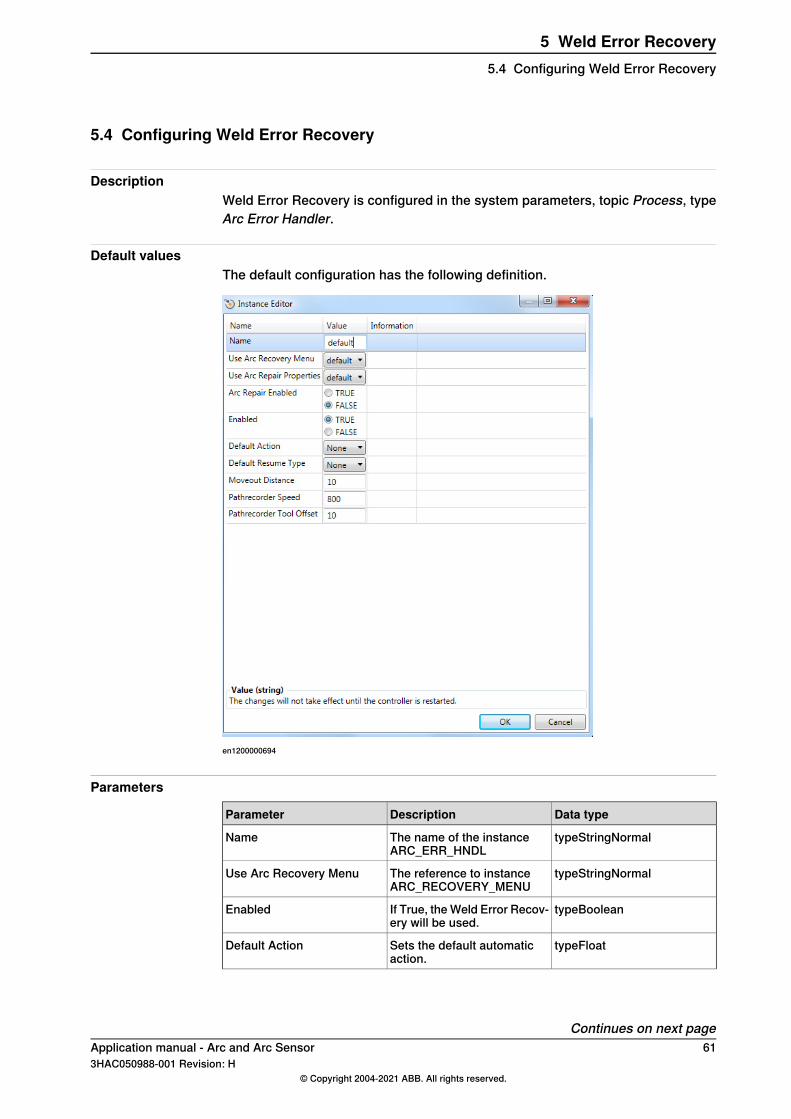
5.4 Configuring Weld Error Recovery
DescriptionWeld Error Recovery is configured in the system parameters, topic Process, typeArc Error Handler.
Default valuesThe default configuration has the following definition.
en1200000694
Parameters
Data typeDescriptionParameter
typeStringNormalThe name of the instanceARC_ERR_HNDL
Name
typeStringNormalThe reference to instanceARC_RECOVERY_MENU
Use Arc Recovery Menu
typeBooleanIf True, the Weld Error Recov-ery will be used.
Enabled
typeFloatSets the default automaticaction.
Default Action
Continues on next pageApplication manual - Arc and Arc Sensor 613HAC050988-001 Revision: H
© Copyright 2004-2021 ABB. All rights reserved.
5 Weld Error Recovery5.4 Configuring Weld Error Recovery
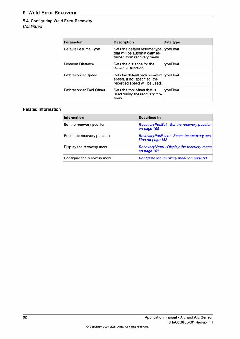
Data typeDescriptionParameter
typeFloatSets the default resume typethat will be automatically re-turned from recovery menu.
Default Resume Type
typeFloatSets the distance for theMoveOut function.
Moveout Distance
typeFloatSets the default path recoveryspeed. If not specified, therecorded speed will be used.
Pathrecorder Speed
typeFloatSets the tool offset that isused during the recovery mo-tions.
Pathrecorder Tool Offset
Related information
Described inInformation
RecoveryPosSet - Set the recovery positionon page 165
Set the recovery position
RecoveryPosReset - Reset the recovery pos-ition on page 168
Reset the recovery position
RecoveryMenu - Display the recovery menuon page 161
Display the recovery menu
Configure the recovery menu on page 63Configure the recovery menu
62 Application manual - Arc and Arc Sensor3HAC050988-001 Revision: H
© Copyright 2004-2021 ABB. All rights reserved.
5 Weld Error Recovery5.4 Configuring Weld Error RecoveryContinued
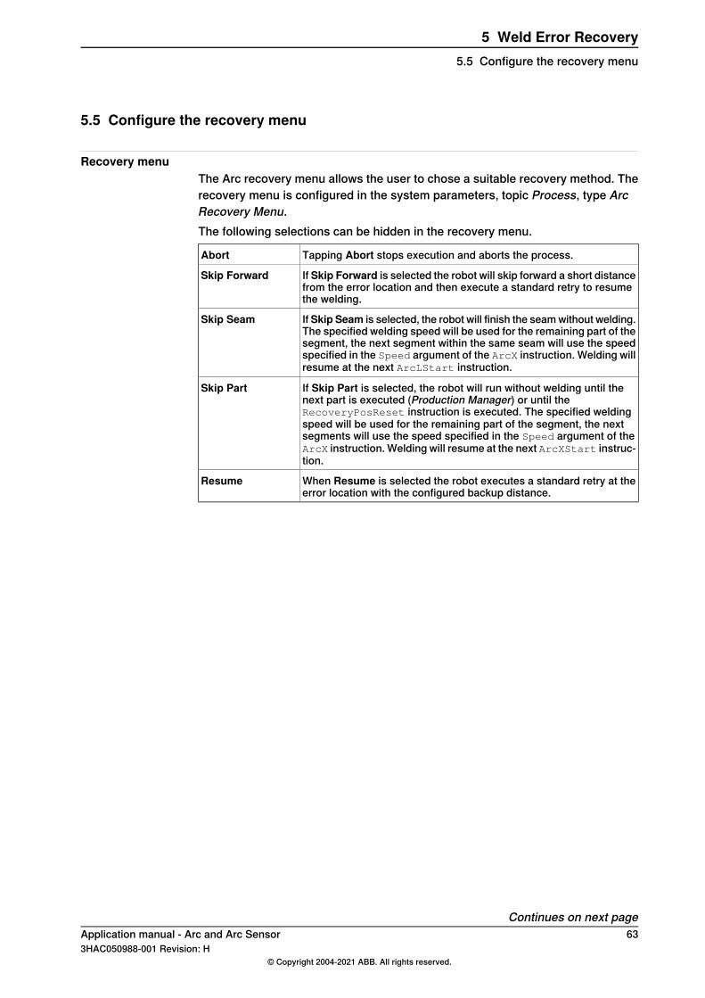
5.5 Configure the recovery menu
Recovery menuThe Arc recovery menu allows the user to chose a suitable recovery method. Therecovery menu is configured in the system parameters, topic Process, type ArcRecovery Menu.The following selections can be hidden in the recovery menu.
Tapping Abort stops execution and aborts the process.Abort
If Skip Forward is selected the robot will skip forward a short distancefrom the error location and then execute a standard retry to resumethe welding.
Skip Forward
If Skip Seam is selected, the robot will finish the seam without welding.The specified welding speed will be used for the remaining part of thesegment, the next segment within the same seam will use the speedspecified in the Speed argument of the ArcX instruction. Welding willresume at the next ArcLStart instruction.
Skip Seam
If Skip Part is selected, the robot will run without welding until thenext part is executed (Production Manager) or until theRecoveryPosReset instruction is executed. The specified weldingspeed will be used for the remaining part of the segment, the nextsegments will use the speed specified in the Speed argument of theArcX instruction. Welding will resume at the next ArcXStart instruc-tion.
Skip Part
When Resume is selected the robot executes a standard retry at theerror location with the configured backup distance.
Resume
Continues on next pageApplication manual - Arc and Arc Sensor 633HAC050988-001 Revision: H
© Copyright 2004-2021 ABB. All rights reserved.
5 Weld Error Recovery5.5 Configure the recovery menu
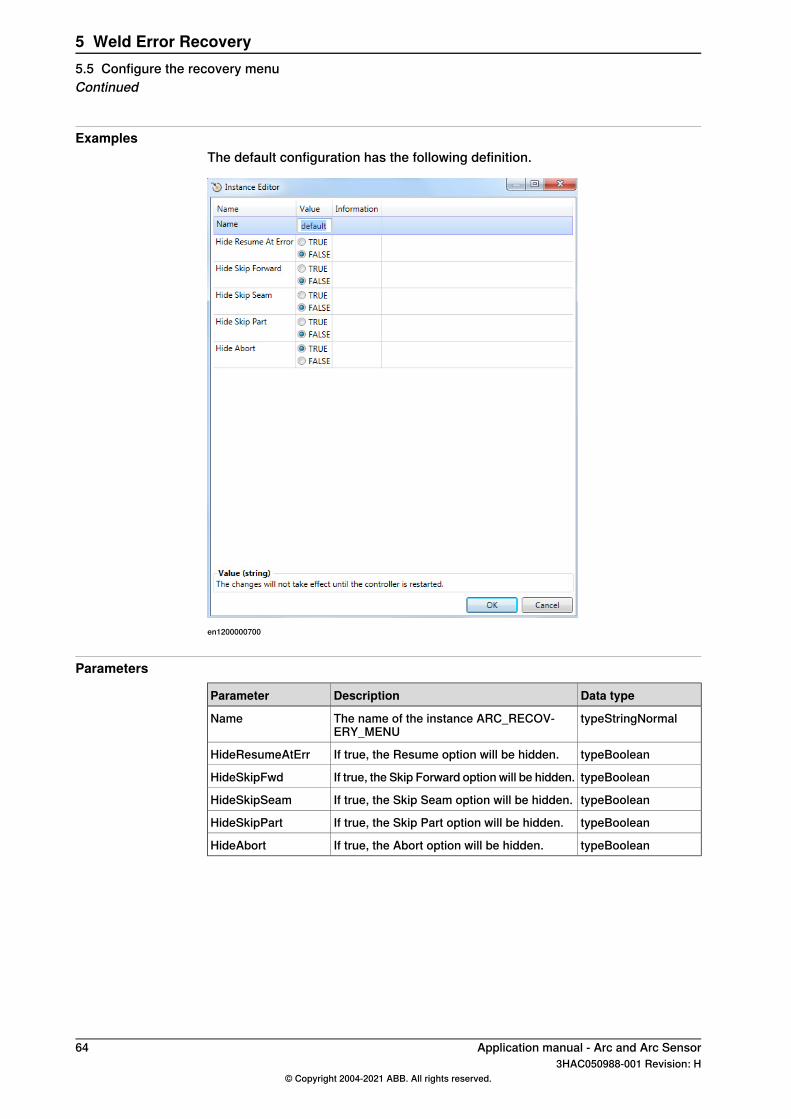
ExamplesThe default configuration has the following definition.
en1200000700
Parameters
Data typeDescriptionParameter
typeStringNormalThe name of the instance ARC_RECOV-ERY_MENU
Name
typeBooleanIf true, the Resume option will be hidden.HideResumeAtErr
typeBooleanIf true, the Skip Forward option will be hidden.HideSkipFwd
typeBooleanIf true, the Skip Seam option will be hidden.HideSkipSeam
typeBooleanIf true, the Skip Part option will be hidden.HideSkipPart
typeBooleanIf true, the Abort option will be hidden.HideAbort
64 Application manual - Arc and Arc Sensor3HAC050988-001 Revision: H
© Copyright 2004-2021 ABB. All rights reserved.
5 Weld Error Recovery5.5 Configure the recovery menuContinued
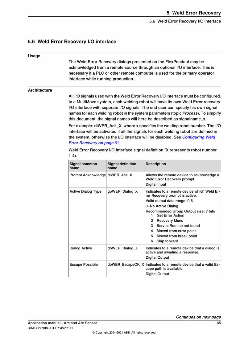
5.6 Weld Error Recovery I/O interface
UsageThe Weld Error Recovery dialogs presented on the FlexPendant may beacknowledged from a remote source through an optional I/O interface. This isnecessary if a PLC or other remote computer is used for the primary operatorinterface while running production.
ArchitectureAll I/O signals used with the Weld Error Recovery I/O interface must be configured.In a MultiMove system, each welding robot will have its own Weld Error recoveryI/O interface with separate I/O signals. The end user can specify his own signalnames for each welding robot in the system parameters (topic Process). To simplifythis document, the signal names will here be described as signalname_x.For example: diWER_Ack_X, where x specifies the welding robot number. The I/Ointerface will be activated if all the signals for each welding robot are defined inthe system, otherwise the I/O interface will be disabled. See Configuring WeldError Recovery on page 61.Weld Error Recovery I/O Interface signal definition (X represents robot number1-4).
DescriptionSignal definitionname
Signal commonname
Allows the remote device to acknowledge aWeld Error Recovery prompt.
diWER_Ack_XPrompt Acknowledge
Digital Input
Indicates to a remote device which Weld Er-ror Recovery prompt is active.
goWER_Dialog_XActive Dialog Type
Valid output data range: 0-60=No Active DialogRecommended Group Output size: 7 bits
1 Get Error Action2 Recovery Menu3 ServiceRoutine not found4 Moved from error point5 Moved from break point6 Skip forward
Indicates to a remote device that a dialog isactive and awaiting a response.
doWER_Dialog_XDialog Active
Digital Output
Indicates to a remote device that a valid Es-cape path is available.
doWER_EscapeOK_XEscape Possible
Digital Output
Continues on next pageApplication manual - Arc and Arc Sensor 653HAC050988-001 Revision: H
© Copyright 2004-2021 ABB. All rights reserved.
5 Weld Error Recovery5.6 Weld Error Recovery I/O interface
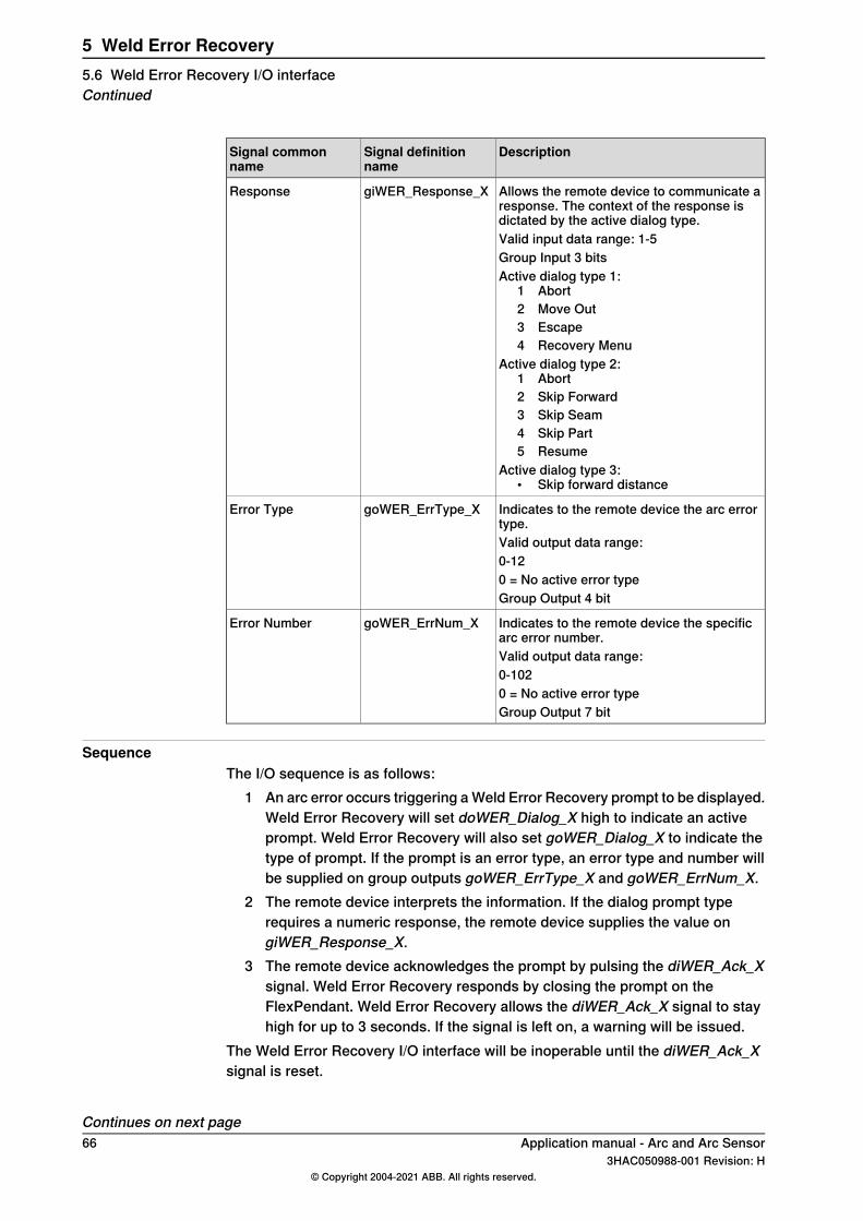
DescriptionSignal definitionname
Signal commonname
Allows the remote device to communicate aresponse. The context of the response isdictated by the active dialog type.
giWER_Response_XResponse
Valid input data range: 1-5Group Input 3 bitsActive dialog type 1:
1 Abort2 Move Out3 Escape4 Recovery Menu
Active dialog type 2:1 Abort2 Skip Forward3 Skip Seam4 Skip Part5 Resume
Active dialog type 3:• Skip forward distance
Indicates to the remote device the arc errortype.
goWER_ErrType_XError Type
Valid output data range:0-120 = No active error typeGroup Output 4 bit
Indicates to the remote device the specificarc error number.
goWER_ErrNum_XError Number
Valid output data range:0-1020 = No active error typeGroup Output 7 bit
SequenceThe I/O sequence is as follows:
1 An arc error occurs triggering a Weld Error Recovery prompt to be displayed.Weld Error Recovery will set doWER_Dialog_X high to indicate an activeprompt. Weld Error Recovery will also set goWER_Dialog_X to indicate thetype of prompt. If the prompt is an error type, an error type and number willbe supplied on group outputs goWER_ErrType_X and goWER_ErrNum_X.
2 The remote device interprets the information. If the dialog prompt typerequires a numeric response, the remote device supplies the value ongiWER_Response_X.
3 The remote device acknowledges the prompt by pulsing the diWER_Ack_Xsignal. Weld Error Recovery responds by closing the prompt on theFlexPendant. Weld Error Recovery allows the diWER_Ack_X signal to stayhigh for up to 3 seconds. If the signal is left on, a warning will be issued.
The Weld Error Recovery I/O interface will be inoperable until the diWER_Ack_Xsignal is reset.
Continues on next page66 Application manual - Arc and Arc Sensor
3HAC050988-001 Revision: H© Copyright 2004-2021 ABB. All rights reserved.
5 Weld Error Recovery5.6 Weld Error Recovery I/O interfaceContinued
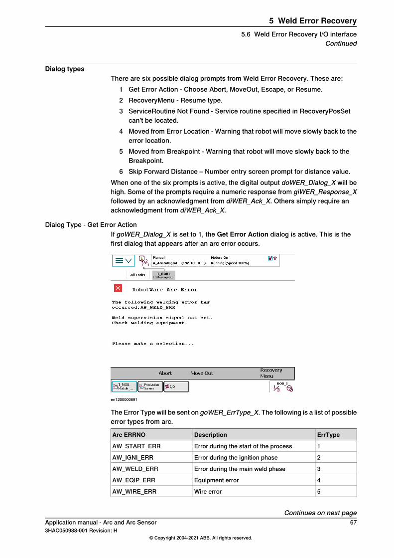
Dialog typesThere are six possible dialog prompts from Weld Error Recovery. These are:
1 Get Error Action - Choose Abort, MoveOut, Escape, or Resume.2 RecoveryMenu - Resume type.3 ServiceRoutine Not Found - Service routine specified in RecoveryPosSet
can't be located.4 Moved from Error Location - Warning that robot will move slowly back to the
error location.5 Moved from Breakpoint - Warning that robot will move slowly back to the
Breakpoint.6 Skip Forward Distance – Number entry screen prompt for distance value.
When one of the six prompts is active, the digital output doWER_Dialog_X will behigh. Some of the prompts require a numeric response from giWER_Response_Xfollowed by an acknowledgment from diWER_Ack_X. Others simply require anacknowledgment from diWER_Ack_X.
Dialog Type - Get Error ActionIf goWER_Dialog_X is set to 1, the Get Error Action dialog is active. This is thefirst dialog that appears after an arc error occurs.
en1200000691
The Error Type will be sent on goWER_ErrType_X. The following is a list of possibleerror types from arc.
ErrTypeDescriptionArc ERRNO
1Error during the start of the processAW_START_ERR
2Error during the ignition phaseAW_IGNI_ERR
3Error during the main weld phaseAW_WELD_ERR
4Equipment errorAW_EQIP_ERR
5Wire errorAW_WIRE_ERR
Continues on next pageApplication manual - Arc and Arc Sensor 673HAC050988-001 Revision: H
© Copyright 2004-2021 ABB. All rights reserved.
5 Weld Error Recovery5.6 Weld Error Recovery I/O interface
Continued
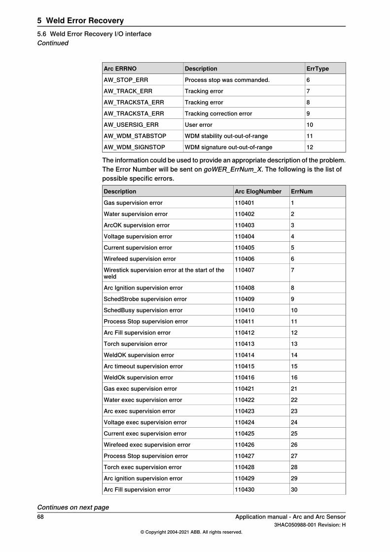
ErrTypeDescriptionArc ERRNO
6Process stop was commanded.AW_STOP_ERR
7Tracking errorAW_TRACK_ERR
8Tracking errorAW_TRACKSTA_ERR
9Tracking correction errorAW_TRACKSTA_ERR
10User errorAW_USERSIG_ERR
11WDM stability out-out-of-rangeAW_WDM_STABSTOP
12WDM signature out-out-of-rangeAW_WDM_SIGNSTOP
The information could be used to provide an appropriate description of the problem.The Error Number will be sent on goWER_ErrNum_X. The following is the list ofpossible specific errors.
ErrNumArc ElogNumberDescription
1110401Gas supervision error
2110402Water supervision error
3110403ArcOK supervision error
4110404Voltage supervision error
5110405Current supervision error
6110406Wirefeed supervision error
7110407Wirestick supervision error at the start of theweld
8110408Arc Ignition supervision error
9110409SchedStrobe supervision error
10110410SchedBusy supervision error
11110411Process Stop supervision error
12110412Arc Fill supervision error
13110413Torch supervision error
14110414WeldOK supervision error
15110415Arc timeout supervision error
16110416WeldOk supervision error
21110421Gas exec supervision error
22110422Water exec supervision error
23110423Arc exec supervision error
24110424Voltage exec supervision error
25110425Current exec supervision error
26110426Wirefeed exec supervision error
27110427Process Stop supervision error
28110428Torch exec supervision error
29110429Arc ignition supervision error
30110430Arc Fill supervision error
Continues on next page68 Application manual - Arc and Arc Sensor
3HAC050988-001 Revision: H© Copyright 2004-2021 ABB. All rights reserved.
5 Weld Error Recovery5.6 Weld Error Recovery I/O interfaceContinued
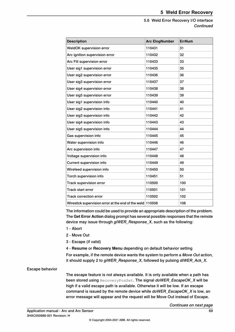
ErrNumArc ElogNumberDescription
31110431WeldOK supervision error
32110432Arc ignition supervision error
33110433Arc Fill supervision error
35110435User sig1 supervision error
36110436User sig2 supervision error
37110437User sig3 supervision error
38110438User sig4 supervision error
39110439User sig5 supervision error
40110440User sig1 supervision info
41110441User sig2 supervision info
42110442User sig3 supervision info
43110443User sig4 supervision info
44110444User sig5 supervision info
45110445Gas supervision info
46110446Water supervision info
47110447Arc supervision info
48110448Voltage supervision info
49110449Current supervision info
50110450Wirefeed supervision info
51110451Torch supervision info
100110500Track supervision error
101110501Track start error
102110502Track correction error
108110508Wirestick supervision error at the end of the weld
The information could be used to provide an appropriate description of the problem.TheGet Error Action dialog prompt has several possible responses that the remotedevice may issue through giWER_Response_X, such as the following:1 - Abort2 - Move Out3 - Escape (if valid)4 - Resume or Recovery Menu depending on default behavior settingFor example, if the remote device wants the system to perform a Move Out action,it should supply 2 to giWER_Response_X, followed by pulsing diWER_Ack_X.
Escape behaviorThe escape feature is not always available. It is only available when a path hasbeen stored using RecoveryPosSet. The signal doWER_EscapeOK_X will behigh if a valid escape path is available. Otherwise it will be low. If an escapecommand is issued by the remote device while doWER_EscapeOK_X is low, anerror message will appear and the request will be Move Out instead of Escape.
Continues on next pageApplication manual - Arc and Arc Sensor 693HAC050988-001 Revision: H
© Copyright 2004-2021 ABB. All rights reserved.
5 Weld Error Recovery5.6 Weld Error Recovery I/O interface
Continued
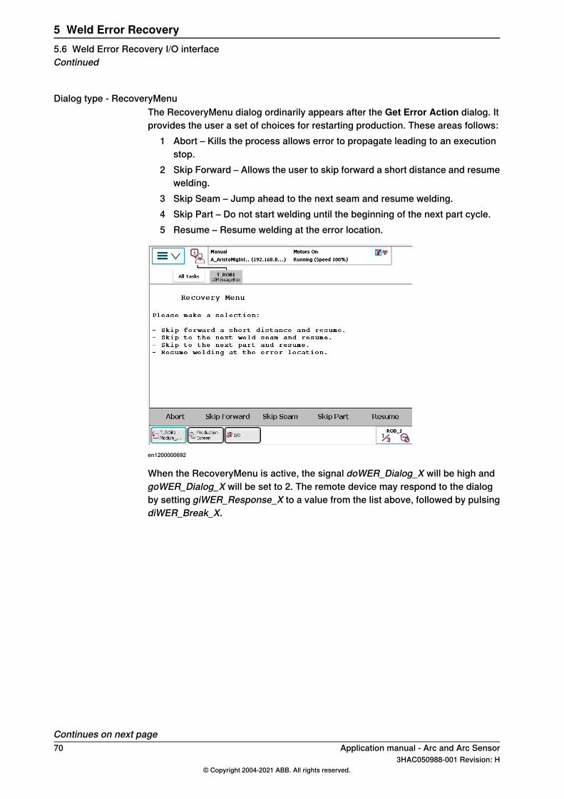
Dialog type - RecoveryMenuThe RecoveryMenu dialog ordinarily appears after the Get Error Action dialog. Itprovides the user a set of choices for restarting production. These areas follows:
1 Abort – Kills the process allows error to propagate leading to an executionstop.
2 Skip Forward – Allows the user to skip forward a short distance and resumewelding.
3 Skip Seam – Jump ahead to the next seam and resume welding.4 Skip Part – Do not start welding until the beginning of the next part cycle.5 Resume – Resume welding at the error location.
en1200000692
When the RecoveryMenu is active, the signal doWER_Dialog_X will be high andgoWER_Dialog_X will be set to 2. The remote device may respond to the dialogby setting giWER_Response_X to a value from the list above, followed by pulsingdiWER_Break_X.
Continues on next page70 Application manual - Arc and Arc Sensor
3HAC050988-001 Revision: H© Copyright 2004-2021 ABB. All rights reserved.
5 Weld Error Recovery5.6 Weld Error Recovery I/O interfaceContinued
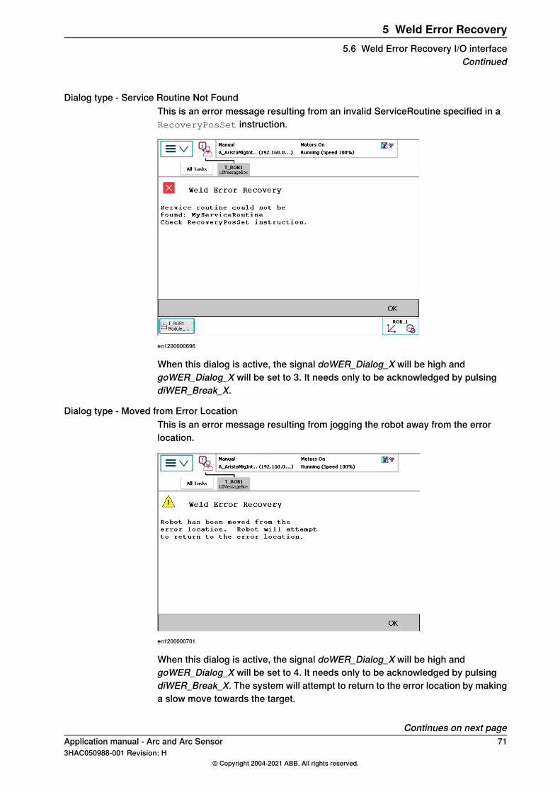
Dialog type - Service Routine Not FoundThis is an error message resulting from an invalid ServiceRoutine specified in aRecoveryPosSet instruction.
en1200000696
When this dialog is active, the signal doWER_Dialog_X will be high andgoWER_Dialog_X will be set to 3. It needs only to be acknowledged by pulsingdiWER_Break_X.
Dialog type - Moved from Error LocationThis is an error message resulting from jogging the robot away from the errorlocation.
en1200000701
When this dialog is active, the signal doWER_Dialog_X will be high andgoWER_Dialog_X will be set to 4. It needs only to be acknowledged by pulsingdiWER_Break_X. The system will attempt to return to the error location by makinga slow move towards the target.
Continues on next pageApplication manual - Arc and Arc Sensor 713HAC050988-001 Revision: H
© Copyright 2004-2021 ABB. All rights reserved.
5 Weld Error Recovery5.6 Weld Error Recovery I/O interface
Continued
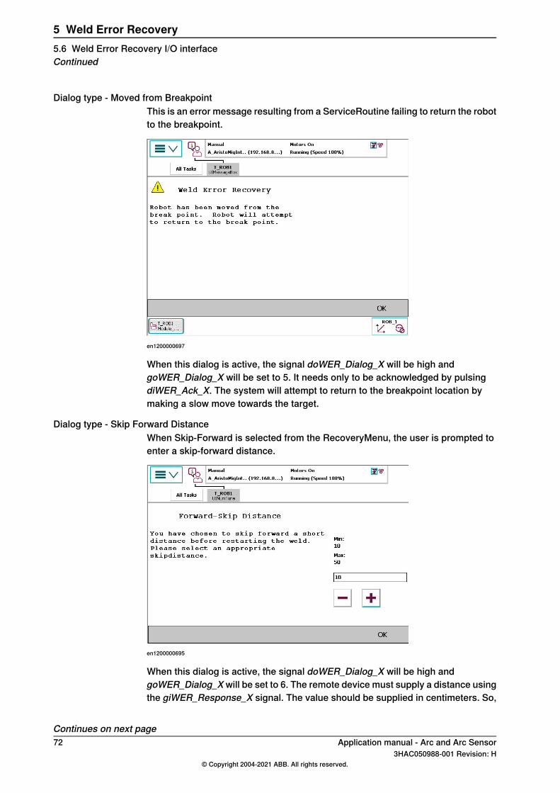
Dialog type - Moved from BreakpointThis is an error message resulting from a ServiceRoutine failing to return the robotto the breakpoint.
en1200000697
When this dialog is active, the signal doWER_Dialog_X will be high andgoWER_Dialog_X will be set to 5. It needs only to be acknowledged by pulsingdiWER_Ack_X. The system will attempt to return to the breakpoint location bymaking a slow move towards the target.
Dialog type - Skip Forward DistanceWhen Skip-Forward is selected from the RecoveryMenu, the user is prompted toenter a skip-forward distance.
en1200000695
When this dialog is active, the signal doWER_Dialog_X will be high andgoWER_Dialog_X will be set to 6. The remote device must supply a distance usingthe giWER_Response_X signal. The value should be supplied in centimeters. So,
Continues on next page72 Application manual - Arc and Arc Sensor
3HAC050988-001 Revision: H© Copyright 2004-2021 ABB. All rights reserved.
5 Weld Error Recovery5.6 Weld Error Recovery I/O interfaceContinued
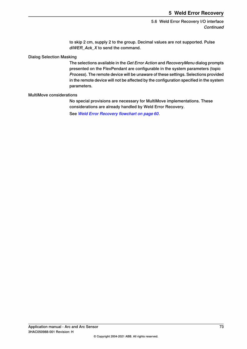
to skip 2 cm, supply 2 to the group. Decimal values are not supported. PulsediWER_Ack_X to send the command.
Dialog Selection MaskingThe selections available in the Get Error Action and RecoveryMenu dialog promptspresented on the FlexPendant are configurable in the system parameters (topicProcess). The remote device will be unaware of these settings. Selections providedin the remote device will not be affected by the configuration specified in the systemparameters.
MultiMove considerationsNo special provisions are necessary for MultiMove implementations. Theseconsiderations are already handled by Weld Error Recovery.See Weld Error Recovery flowchart on page 60.
Application manual - Arc and Arc Sensor 733HAC050988-001 Revision: H
© Copyright 2004-2021 ABB. All rights reserved.
5 Weld Error Recovery5.6 Weld Error Recovery I/O interface
Continued
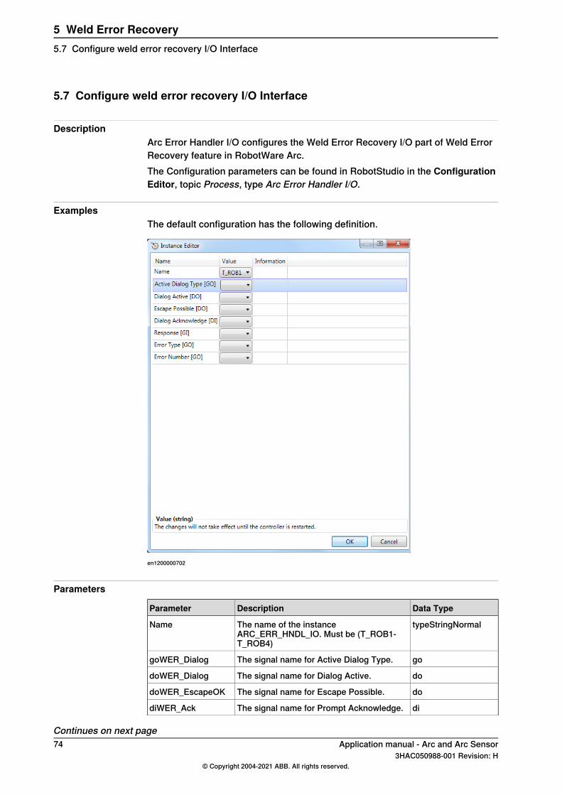
5.7 Configure weld error recovery I/O Interface
DescriptionArc Error Handler I/O configures the Weld Error Recovery I/O part of Weld ErrorRecovery feature in RobotWare Arc.The Configuration parameters can be found in RobotStudio in the ConfigurationEditor, topic Process, type Arc Error Handler I/O.
ExamplesThe default configuration has the following definition.
en1200000702
Parameters
Data TypeDescriptionParameter
typeStringNormalThe name of the instanceARC_ERR_HNDL_IO. Must be (T_ROB1-T_ROB4)
Name
goThe signal name for Active Dialog Type.goWER_Dialog
doThe signal name for Dialog Active.doWER_Dialog
doThe signal name for Escape Possible.doWER_EscapeOK
diThe signal name for Prompt Acknowledge.diWER_Ack
Continues on next page74 Application manual - Arc and Arc Sensor
3HAC050988-001 Revision: H© Copyright 2004-2021 ABB. All rights reserved.
5 Weld Error Recovery5.7 Configure weld error recovery I/O Interface
Data TypeDescriptionParameter
giThe signal name for Response.giWER_Response
goThe signal name for Error Type.goWER_ErrType
goThe signal name for Error Number.goWER_ErrNum
Related information
Described inInformation
RecoveryPosSet - Set the recovery positionon page 165
Set the recovery position
RecoveryPosReset - Reset the recovery pos-ition on page 168
Reset the recovery position
RecoveryMenu - Display the recovery menuon page 161
Display the recovery menu
Configure the recovery menu on page 63Configure the recovery menu
Application manual - Arc and Arc Sensor 753HAC050988-001 Revision: H
© Copyright 2004-2021 ABB. All rights reserved.
5 Weld Error Recovery5.7 Configure weld error recovery I/O Interface
Continued
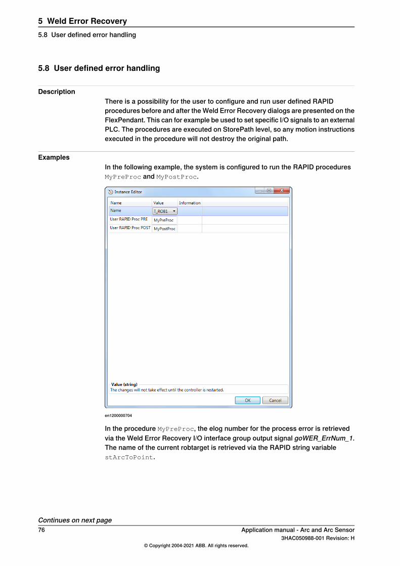
5.8 User defined error handling
DescriptionThere is a possibility for the user to configure and run user defined RAPIDprocedures before and after the Weld Error Recovery dialogs are presented on theFlexPendant. This can for example be used to set specific I/O signals to an externalPLC. The procedures are executed on StorePath level, so any motion instructionsexecuted in the procedure will not destroy the original path.
ExamplesIn the following example, the system is configured to run the RAPID proceduresMyPreProc and MyPostProc.
en1200000704
In the procedure MyPreProc, the elog number for the process error is retrievedvia the Weld Error Recovery I/O interface group output signal goWER_ErrNum_1.The name of the current robtarget is retrieved via the RAPID string variablestArcToPoint.
Continues on next page76 Application manual - Arc and Arc Sensor
3HAC050988-001 Revision: H© Copyright 2004-2021 ABB. All rights reserved.
5 Weld Error Recovery5.8 User defined error handling
In the procedure MyPostProc, the selected resume type in the Recovery Menu isretrieved via the RAPID variable nAEResumeType.
Program exampleMODULE ErrorHandling
PROC MyPreProc()
VAR num nErrNo;
VAR string stJointName;
! Get Errornumber
nErrNo:=GetArcErrNo();
! Get Jointnumber
stJointName:=GetJointNumber();
UIMsgBox \Header:="MyPreProc T_ROB1", "Failing robtarget name:"+stJointName\MsgLine2:="Arc Elog error:"+ValToStr(nErrNo);
ENDPROC
PROC MyPostProc()
VAR string stBtnSelected;
TEST nAEResumeType
CASE RESUME_KILL:
stBtnSelected:="Abort";
CASE RESUME_SKIP_FWD:
stBtnSelected:="Skip FWD";
CASE RESUME_SKIP_SEAM:
stBtnSelected:="Skip Seam";
CASE RESUME_SKIP_PART:
stBtnSelected:="Skip Part";
CASE RESUME_SKIP_OFF:
stBtnSelected:="Resume";
ENDTEST
UIMsgBox \Header:="MyPostProc T_ROB1", "Selected action:"+stBtnSelected;
ENDPROC
FUNC num GetArcErrNo()
RETURN GOutput(goWER_ErrNum_1);
ENDFUNC
FUNC string GetJointNumber()
RETURN stArcToPoint;
ENDFUNC
ENDMODULE
Application manual - Arc and Arc Sensor 773HAC050988-001 Revision: H
© Copyright 2004-2021 ABB. All rights reserved.
5 Weld Error Recovery5.8 User defined error handling
Continued
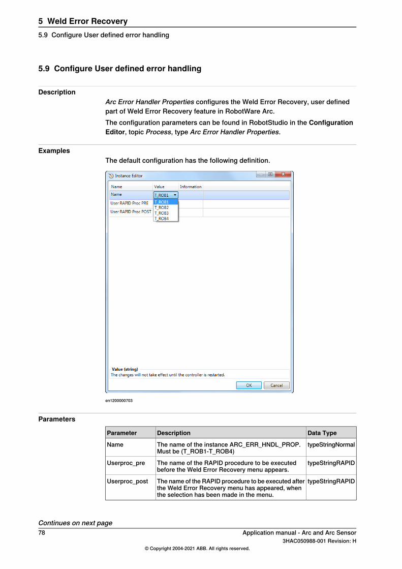
5.9 Configure User defined error handling
DescriptionArc Error Handler Properties configures the Weld Error Recovery, user definedpart of Weld Error Recovery feature in RobotWare Arc.The configuration parameters can be found in RobotStudio in the ConfigurationEditor, topic Process, type Arc Error Handler Properties.
ExamplesThe default configuration has the following definition.
en1200000703
Parameters
Data TypeDescriptionParameter
typeStringNormalThe name of the instance ARC_ERR_HNDL_PROP.Must be (T_ROB1-T_ROB4)
Name
typeStringRAPIDThe name of the RAPID procedure to be executedbefore the Weld Error Recovery menu appears.
Userproc_pre
typeStringRAPIDThe name of the RAPID procedure to be executed afterthe Weld Error Recovery menu has appeared, whenthe selection has been made in the menu.
Userproc_post
Continues on next page78 Application manual - Arc and Arc Sensor
3HAC050988-001 Revision: H© Copyright 2004-2021 ABB. All rights reserved.
5 Weld Error Recovery5.9 Configure User defined error handling
Related information
Described inInformation
RecoveryPosSet - Set the recovery positionon page 165
Set the recovery position
RecoveryPosReset - Reset the recovery pos-ition on page 168
Reset the recovery position
RecoveryMenu - Display the recovery menuon page 161
Display the recovery menu
Configure the recovery menu on page 63Configure the recovery menu
Application manual - Arc and Arc Sensor 793HAC050988-001 Revision: H
© Copyright 2004-2021 ABB. All rights reserved.
5 Weld Error Recovery5.9 Configure User defined error handling
Continued

This page is intentionally left blank
6 Weld Repair6.1 Introduction
BackgroundWhen welding synchronized with two or more welding robots and a positioner,weld errors can sometimes occur in one of the welding robots. Since the motionand process is synchronized, the welding robot without weld error will also stopand perform error handling. Using the functionality Weld Repair will shut down thearc only in the failing robot while the others are continuing its weld. The faulty seamis automatically re-welded at the error location.
Functional descriptionIf a part is welded in synchronized coordinated mode and a weld error is detected(for example, the ArcEst signal goes low for robot 1), the robot will continue itsmovement to the end of the weld and is not forced to stop by RobotWare Arc. Theother robots are also continuing its weld. The weld error is detected internally anda fully automatic weld repair can be done after the robots reached the instructionArcLEnd.The robots are moving backwards on path (with the help of the path recorder) intoa service position and do an automatic re-weld of the seam (move with weldingblocked until the error position is reached). All robots can move at the same timeas only one weld error has been detected. The number of automatic repair retriesis configured in the system parameters (PROC.cfg). If an ignition error or welderror is detected during the repair phase a retry can be done. If all weld repairs aredone the robots can continue with the next seam.If multiple errors are detected (for example, ArcEst goes low for more then onerobot on different locations within a seam) then the behavior is the same asdescribed but with the exception that now only one robot at the time can do there-weld. The other welding robot(s) are moving with blocked welding.If for some reason the re-weld failed again than the robots are moving backwardson path into the service position. User code can be executed in service position,for example, to communicate with a PLC and inform the operator that the re-weldfailed. It is possible to continue the program from here on RAPID level to have thepossibility to move to the next seam.It is also possible to display a message on the FlexPendant to interact with theoperator to continue production.
Weld Repair limitations• Each weld has to be defined in its own procedure.• Only synchronized motions can be used in the procedure. No independent
movements after a SynchMoveOff instruction.• The correct procedure name must be provided in the instruction
SetWRProcName.
Continues on next pageApplication manual - Arc and Arc Sensor 813HAC050988-001 Revision: H
© Copyright 2004-2021 ABB. All rights reserved.
6 Weld Repair6.1 Introduction
• In a FlexPositioner setup, the optional argument \FlexPositioner mustbe used in the instruction SetWRProcName in the non-welding task/robot.
• ArcMoveExtJ\Start must be used to indicate start to correspondingArcLStart instruction (synchronized).
• Program displacement with the instruction PDispSet is not supported.
Addition to RobotWare Arc• Two new instructions are introduced:• RecoveryMenuWR-
- SetWRProcName
• A new data type advSeamData is introduced• A new optional argument \Start is introduced to all ArcMoveX instructions• A new optional argument \advData is introduced to the ArcXStart
instructions• New PLC codes (active dialog types) for the weld error recovery I/O interface• Active Dialog Type Value 7 – RecoveryMenuWR prompted-
- Active Dialog Type Value 8 – Weld Repair Menu prompted
82 Application manual - Arc and Arc Sensor3HAC050988-001 Revision: H
© Copyright 2004-2021 ABB. All rights reserved.
6 Weld Repair6.1 IntroductionContinued
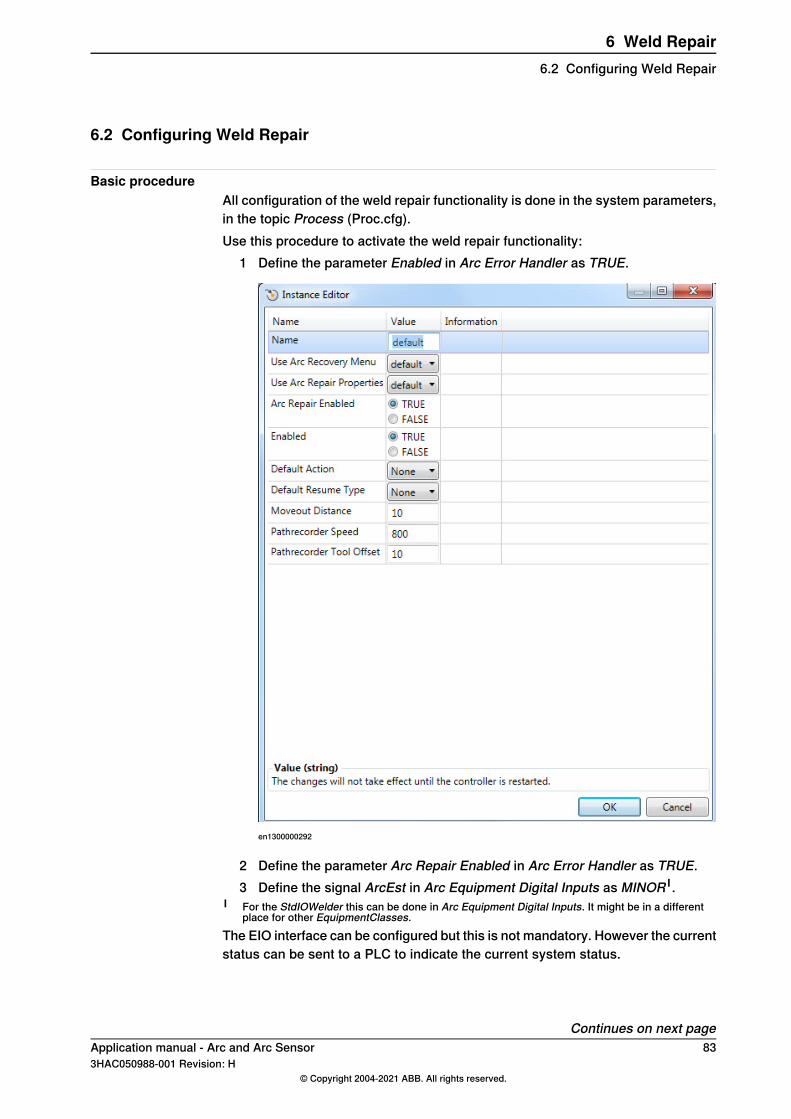
6.2 Configuring Weld Repair
Basic procedureAll configuration of the weld repair functionality is done in the system parameters,in the topic Process (Proc.cfg).Use this procedure to activate the weld repair functionality:
1 Define the parameter Enabled in Arc Error Handler as TRUE.
en1300000292
2 Define the parameter Arc Repair Enabled in Arc Error Handler as TRUE.3 Define the signal ArcEst in Arc Equipment Digital Inputs as MINOR I .
I For the StdIOWelder this can be done in Arc Equipment Digital Inputs. It might be in a differentplace for other EquipmentClasses.
The EIO interface can be configured but this is not mandatory. However the currentstatus can be sent to a PLC to indicate the current system status.
Continues on next pageApplication manual - Arc and Arc Sensor 833HAC050988-001 Revision: H
© Copyright 2004-2021 ABB. All rights reserved.
6 Weld Repair6.2 Configuring Weld Repair
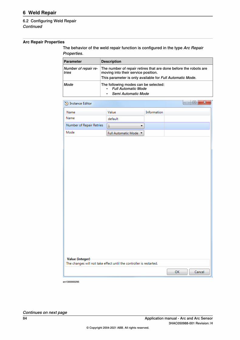
Arc Repair PropertiesThe behavior of the weld repair function is configured in the type Arc RepairProperties.
DescriptionParameter
The number of repair retires that are done before the robots aremoving into their service position.
Number of repair re-tries
This parameter is only available for Full Automatic Mode.
The following modes can be selected:• Full Automatic Mode• Semi Automatic Mode
Mode
en1300000295
Continues on next page84 Application manual - Arc and Arc Sensor
3HAC050988-001 Revision: H© Copyright 2004-2021 ABB. All rights reserved.
6 Weld Repair6.2 Configuring Weld RepairContinued
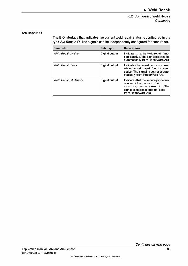
Arc Repair IOThe EIO interface that indicates the current weld repair status is configured in thetype Arc Repair IO. The signals can be independently configured for each robot.
DescriptionData typeParameter
Indicates that the weld repair func-tion is active. The signal is set/resetautomatically from RobotWare Arc.
Digital outputWeld Repair Active
Indicates that a weld error occurredwhile the weld repair function wasactive. The signal is set/reset auto-matically from RobotWare Arc.
Digital outputWeld Repair Error
Indicates that the service procedureconnected to the instructionRecoveryPosSet is executed. Thesignal is set/reset automaticallyfrom RobotWare Arc.
Digital outputWeld Repair at Service
Continues on next pageApplication manual - Arc and Arc Sensor 853HAC050988-001 Revision: H
© Copyright 2004-2021 ABB. All rights reserved.
6 Weld Repair6.2 Configuring Weld Repair
Continued
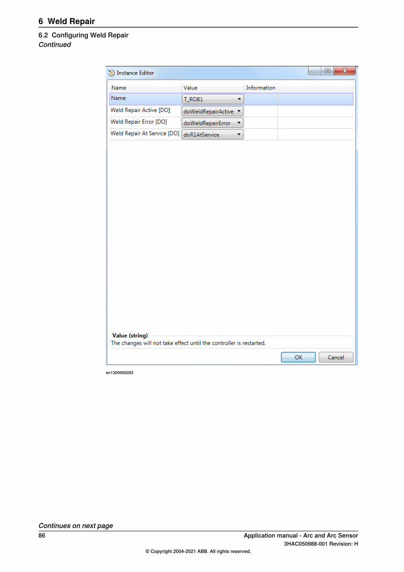
en1300000293
Continues on next page86 Application manual - Arc and Arc Sensor
3HAC050988-001 Revision: H© Copyright 2004-2021 ABB. All rights reserved.
6 Weld Repair6.2 Configuring Weld RepairContinued
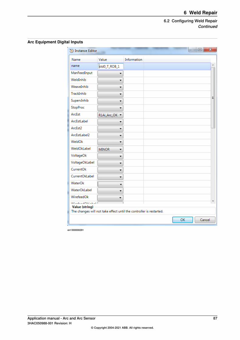
Arc Equipment Digital Inputs
en1300000291
Application manual - Arc and Arc Sensor 873HAC050988-001 Revision: H
© Copyright 2004-2021 ABB. All rights reserved.
6 Weld Repair6.2 Configuring Weld Repair
Continued
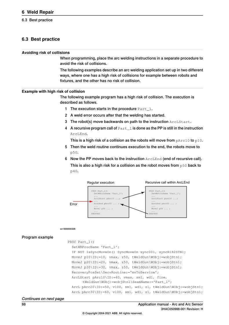
6.3 Best practice
Avoiding risk of collisionsWhen programming, place the arc welding instructions in a separate procedure toavoid the risk of collisions.The following examples describe an arc welding application set up in two differentways, where one has a high risk of collisions for example between robots andfixtures, and the other has no risk of collision.
Example with high risk of collisionThe following example program has a high risk of collision. The execution isdescribed as follows.
1 The execution starts in the procedure Part_1.2 A weld error occurs after that the welding has started.3 The robot(s) move backwards on path to the instruction ArcLStart.4 A recursive program call of Part_1 is done as the PP is still in the instruction
ArcLEnd.This is a high risk of a collision as the robots will move from pArc10 to p10.
5 Then the weld routine continues execution to the end, the robots move top50.
6 Now the PP moves back to the instruction ArcLEnd (end of recursive call).This is also a high risk for a collision as the robot moves from p50 back top40.
PROC Part_1()
SetWRProcName "Part_1";
...
ArcLStart pArc10 ...;
...
ArcLEnd pArc50 ... ;
...
MoveJ p50 ... ;
...
ENDPROC
PROC Part_1()
SetWRProcName "Part_1";
...
ArcLStart pArc10 ...;
...
ArcLEnd pArc50 ... ;
...
MoveJ p50 ... ;
...
ENDPROC
Recursive call within ArcLEndRegular execution
Error
xx1300000328
Program examplePROC Part_1()
SetWRProcName "Part_1";
IF NOT IsSyncMoveOn() SyncMoveOn sync001, syncR1R2STN1;
MoveJ p10\ID:=10, vmax, z50, tWeldGun\WObj:=wobjStn1;
MoveJ p20\ID:=20, vmax, z50, tWeldGun\WObj:=wobjStn1;
MoveJ p30\ID:=30, vmax, z50, tWeldGun\WObj:=wobjStn1;
RecoveryPosSet\ServRoutine:="mvToService";
ArcLStart pArc10\ID:=40, vmax, sm1, wd1, fine,tWeldGun\WObj:=wobjStn1\SeamName:="Part_1";
ArcL pArc20\ID:=50, v100, sm1, wd1, z1, tWeldGun\WObj:=wobjStn1;
ArcL pArc30\ID:=60, v100, sm1, wd1, z1, tWeldGun\WObj:=wobjStn1;
Continues on next page88 Application manual - Arc and Arc Sensor
3HAC050988-001 Revision: H© Copyright 2004-2021 ABB. All rights reserved.
6 Weld Repair6.3 Best practice
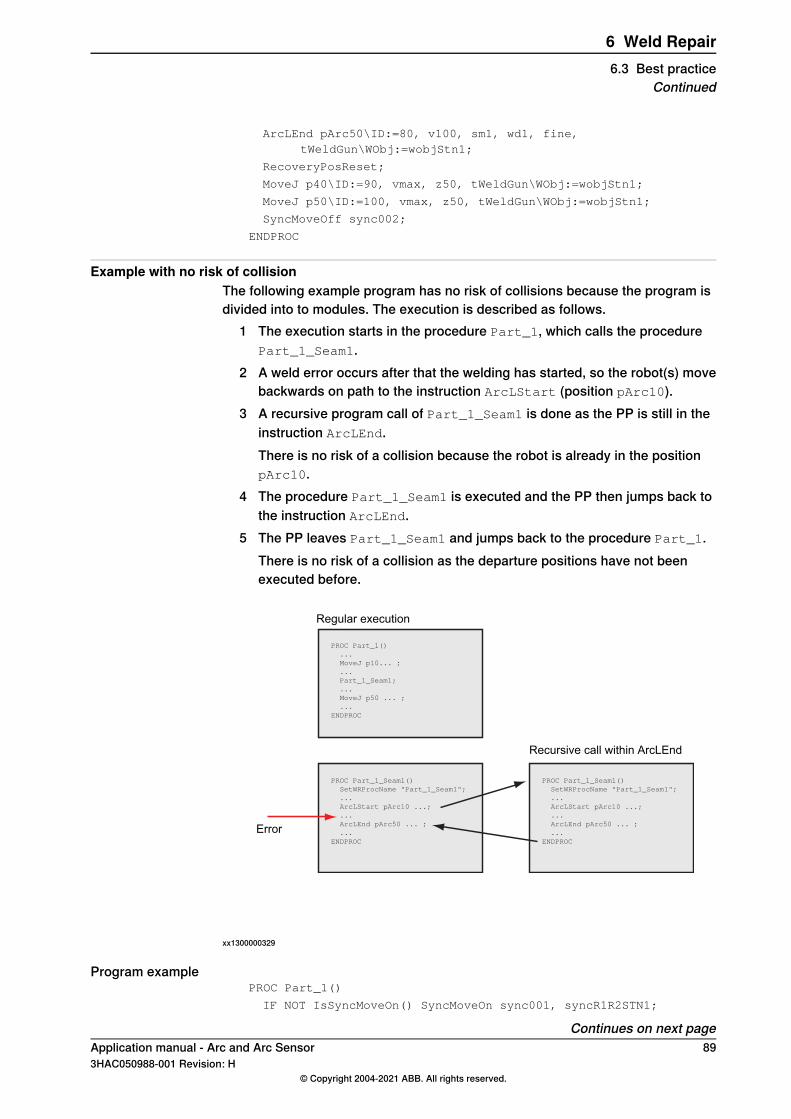
ArcLEnd pArc50\ID:=80, v100, sm1, wd1, fine,tWeldGun\WObj:=wobjStn1;
RecoveryPosReset;
MoveJ p40\ID:=90, vmax, z50, tWeldGun\WObj:=wobjStn1;
MoveJ p50\ID:=100, vmax, z50, tWeldGun\WObj:=wobjStn1;
SyncMoveOff sync002;
ENDPROC
Example with no risk of collisionThe following example program has no risk of collisions because the program isdivided into to modules. The execution is described as follows.
1 The execution starts in the procedure Part_1, which calls the procedurePart_1_Seam1.
2 A weld error occurs after that the welding has started, so the robot(s) movebackwards on path to the instruction ArcLStart (position pArc10).
3 A recursive program call of Part_1_Seam1 is done as the PP is still in theinstruction ArcLEnd.There is no risk of a collision because the robot is already in the positionpArc10.
4 The procedure Part_1_Seam1 is executed and the PP then jumps back tothe instruction ArcLEnd.
5 The PP leaves Part_1_Seam1 and jumps back to the procedure Part_1.There is no risk of a collision as the departure positions have not beenexecuted before.
PROC Part_1()
...
MoveJ p10... ;
...
Part_1_Seam1;
...
MoveJ p50 ... ;
...
ENDPROC
PROC Part_1_Seam1()
SetWRProcName "Part_1_Seam1";
...
ArcLStart pArc10 ...;
...
ArcLEnd pArc50 ... ;
...
ENDPROC
PROC Part_1_Seam1()
SetWRProcName "Part_1_Seam1";
...
ArcLStart pArc10 ...;
...
ArcLEnd pArc50 ... ;
...
ENDPROC
Recursive call within ArcLEnd
Regular execution
Error
xx1300000329
Program examplePROC Part_1()
IF NOT IsSyncMoveOn() SyncMoveOn sync001, syncR1R2STN1;
Continues on next pageApplication manual - Arc and Arc Sensor 893HAC050988-001 Revision: H
© Copyright 2004-2021 ABB. All rights reserved.
6 Weld Repair6.3 Best practice
Continued
MoveJ p10\ID:=10, vmax, z50, tWeldGun\WObj:=wobjStn1;
MoveJ p20\ID:=20, vmax, z50, tWeldGun\WObj:=wobjStn1;
MoveJ p30\ID:=30, vmax, z50, tWeldGun\WObj:=wobjStn1;
Part_1_Seam1;
MoveJ p40\ID:=90, vmax, z50, tWeldGun\WObj:=wobjStn1;
MoveJ p50\ID:=100, vmax, z50, tWeldGun\WObj:=wobjStn1;
SyncMoveOff sync002;
ENDPROC
PROC Part_1_Seam1()
SetWRProcName "Part_1_Seam1";
IF NOT IsSyncMoveOn() SyncMoveOn sync001, syncR1R2STN1;
RecoveryPosSet\ServRoutine:="mvToService";
ArcLStart pArc10\ID:=40, vmax, sm1, wd1, fine,tWeldGun\WObj:=wobjStn1\SeamName:="Part_1_Seam1";
ArcL pArc20\ID:=50, v100, sm1, wd1, z1, tWeldGun\WObj:=wobjStn1;
ArcL pArc30\ID:=60, v100, sm1, wd1, z1, tWeldGun\WObj:=wobjStn1;
ArcLEnd pArc50\ID:=80, v100, sm1, wd1, fine,tWeldGun\WObj:=wobjStn1;
RecoveryPosReset;
ENDPROC
90 Application manual - Arc and Arc Sensor3HAC050988-001 Revision: H
© Copyright 2004-2021 ABB. All rights reserved.
6 Weld Repair6.3 Best practiceContinued
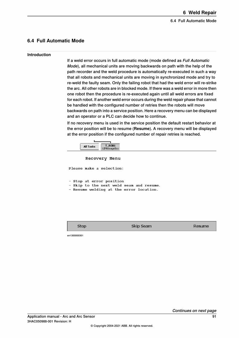
6.4 Full Automatic Mode
IntroductionIf a weld error occurs in full automatic mode (mode defined as Full AutomaticMode), all mechanical units are moving backwards on path with the help of thepath recorder and the weld procedure is automatically re-executed in such a waythat all robots and mechanical units are moving in synchronized mode and try tore-weld the faulty seam. Only the failing robot that had the weld error will re-strikethe arc. All other robots are in blocked mode. If there was a weld error in more thenone robot then the procedure is re-executed again until all weld errors are fixedfor each robot. If another weld error occurs during the weld repair phase that cannotbe handled with the configured number of retries then the robots will movebackwards on path into a service position. Here a recovery menu can be displayedand an operator or a PLC can decide how to continue.If no recovery menu is used in the service position the default restart behavior atthe error position will be to resume (Resume). A recovery menu will be displayedat the error position if the configured number of repair retries is reached.
en1300000301
Continues on next pageApplication manual - Arc and Arc Sensor 913HAC050988-001 Revision: H
© Copyright 2004-2021 ABB. All rights reserved.
6 Weld Repair6.4 Full Automatic Mode
Program examples for Full Automatic ModeThe following examples describe scenarios of how the weld repair functionalityreacts on ignition errors and weld errors in full automatic mode. All scenarios arebased on synchronized welds and related to the program examples below.
Note
Make sure to use the correct name (SetWRProcName) in the welding sequenceto inform Robotware Arc which weld procedure should be re-executed with theweld repair function. There might be a risk that the welding equipment, forexample the welding gun, gets damaged if the wrong procedure name is specified.ArcMoveExtJ\Start must be used in the positioner's task to indicate start tocorresponding ArcLStart instruction.
Example program for robot 1Each weld is in a separate procedure to avoid collisions if the Weld Repair sequenceis active.
MODULE R1_Part_A
PROC PART_1_R1()
IF NOT IsSyncMoveOn() SyncMoveOn sync001, syncR1R2STN1;
! Approach positions towards the weld
MoveJ p10\ID:=10, vmax, z50, tWeldGun\WObj:=wobjStn1;
MoveJ p20\ID:=20, vmax, z50, tWeldGun\WObj:=wobjStn1;
MoveJ p30\ID:=30, vmax, z50, tWeldGun\WObj:=wobjStn1;
R1_Part1_Seam1;
! Depart positions
MoveJ p40\ID:=90, vmax, z50, tWeldGun\WObj:=wobjStn1;
MoveJ p50\ID:=100, vmax, z50, tWeldGun\WObj:=wobjStn1;
MoveJ p60\ID:=110, vmax, z50, tWeldGun\WObj:=wobjStn1;
SyncMoveOff sync002;
ENDPROC
PROC R1_Part1_Seam1()
! Inform RobotWare Arc which procedure shall be re-executed
SetWRProcName "R1_Part1_Seam1";
IF NOT IsSyncMoveOn() SyncMoveOn sync001, syncR1R2STN1;
! Set Recovery Position, here it will be "p30" from exampleabove
! Turn on PathRecorder
RecoveryPosSet\ServRoutine:="mvToService";
ArcLStart pArc10\ID:=40, vmax, sm1, wd1, fine,tWeldGun\WObj:=wobjStn1\SeamName:="R1_Part1_Seam1";
ArcL pArc20\ID:=50, v100, sm1, wd1, z1, tWeldGun\WObj:=wobjStn1;
ArcL pArc30\ID:=60, v100, sm1, wd1, z1, tWeldGun\WObj:=wobjStn1;
Continues on next page92 Application manual - Arc and Arc Sensor
3HAC050988-001 Revision: H© Copyright 2004-2021 ABB. All rights reserved.
6 Weld Repair6.4 Full Automatic ModeContinued
ArcC pArc40, pArc50\ID:=70, v100, sm1, wd1, z1,tWeldGun\WObj:=wobjStn1;
ArcLEnd pArc50\ID:=80, v100, sm1, wd1, fine,tWeldGun\WObj:=wobjStn1;
! Turn off PathRecorder
RecoveryPosReset;
ENDPROC
ENDMODULE
Example program for robot 2Each weld is in a separate procedure to avoid collisions if the Weld Repair sequenceis active.
MODULE R1_Part_A
PROC PART_1_R2()
IF NOT IsSyncMoveOn() SyncMoveOn sync001, syncR1R2STN1;
! Approach positions towards the weld
MoveJ p10\ID:=10, vmax, z50, tWeldGun\WObj:=wobjStn1;
MoveJ p20\ID:=20, vmax, z50, tWeldGun\WObj:=wobjStn1;
MoveJ p30\ID:=30, vmax, z50, tWeldGun\WObj:=wobjStn1;
R2_Part1_Seam1;
! Departure positions
MoveJ p40\ID:=90, vmax, z50, tWeldGun\WObj:=wobjStn1;
MoveJ p50\ID:=100, vmax, z50,tWeldGun\WObj:=wobjStn1;
MoveJ p60\ID:=110, vmax, z50,tWeldGun\WObj:=wobjStn1;
SyncMoveOff sync002;
ENDPROC
PROC R2_Part1_Seam1()
! Define which procedure shall be re-executed
SetWRProcName "R2_Part1_Seam1";
IF NOT IsSyncMoveOn() SyncMoveOn sync001, syncR1R2STN1;
! Set Recovery Position, here it will be "p30" from exampleabove
! Turn on PathRecorder
RecoveryPosSet\ServRoutine:="mvToService";
ArcLStart pArc10\ID:=40, vmax, sm1, wd1, fine,tWeldGun\WObj:=wobjStn1\SeamName:="R2_Part1_Seam1";
ArcL pArc20\ID:=50, v100, sm1, wd1, z1, tWeldGun\WObj:=wobjStn1;
ArcL pArc30\ID:=60, v100, sm1, wd1, z1, tWeldGun\WObj:=wobjStn1;
ArcC pArc40, pArc50\ID:=70, v100, sm1, wd1, z1,tWeldGun\WObj:=wobjStn1;
ArcLEnd pArc60\ID:=80, v100, sm1, wd1, fine,tWeldGun\WObj:=wobjStn1;
Continues on next pageApplication manual - Arc and Arc Sensor 933HAC050988-001 Revision: H
© Copyright 2004-2021 ABB. All rights reserved.
6 Weld Repair6.4 Full Automatic Mode
Continued
! Turn off PathRecorder
RecoveryPosReset;
ENDPROC
ENDMODULE
Example program for STN1Each weld is in a separate procedure to avoid collisions if the Weld Repair sequenceis active.
MODULE STN1_Part_A
PROC STN1_Part1()
IF NOT IsMechUnitActive(STN1) ActUnit STN1;
IF NOT IsSyncMoveOn() SyncMoveOn sync001, Alle_STN1;
MoveExtJ p10\ID:=10,vmax,z50;
MoveExtJ p20\ID:=20,vmax,z50;
MoveExtJ p30\ID:=30,vmax,z50;
STN1_Part1_Seam1;
MoveExtJ p40\ID:=90,vmax,z50;
MoveExtJ p50\ID:=100,vmax,z50;
MoveExtJ p60\ID:=110,vmax,z50;
SyncMoveOff sync002;
ENDPROC
PROC STN1_Part1_Seam1()
! Define which procedure shall be re-executed
SetWRProcName "STN1_Part1_Seam1";
IF NOT IsMechUnitActive(STN1) ActUnit STN1;
IF NOT IsSyncMoveOn() SyncMoveOn sync001, Alle_STN1;
! Set Recovery Position, here it will be "p30" from exampleabove
! Turn on PathRecorder
RecoveryPosSet\ServRoutine:="mvToService";
! Optional argument "\Start" set to the corresponding ArcLStartinstruction
ArcMoveExtJ pArc10\ID:=40,vmax,fine\Start;
ArcMoveExtJ pArc20\ID:=50,vrot50,z1;
ArcMoveExtJ pArc30\ID:=60,vrot50,z1;
ArcMoveExtJ pArc40\ID:=70,vrot50,z1;
ArcMoveExtJ pArc50\ID:=80,vrot50,fine;
! Turn off PathRecorder
RecoveryPosReset;
ENDPROC
ENDMODULE
Continues on next page94 Application manual - Arc and Arc Sensor
3HAC050988-001 Revision: H© Copyright 2004-2021 ABB. All rights reserved.
6 Weld Repair6.4 Full Automatic ModeContinued
Example program for a service routinePROC mvToService()
VAR bool bTaskInSync:=FALSE;
! Check if in synchronized mode
IF IsSyncMoveOn() bTaskInSync:=TRUE;
GetCurrentPosition pEnter\Tool:= tWeldGun \Wobj:=wobj0;
! Suspend synchronization, robots are now in independent mode
IF bTaskInSync SyncMoveSuspend;
IF GetProcErr() THEN
MoveJ pService, v500, fine, tWeldGun\WObj:=wobj0;
RecoveryMenuWR;
ENDIF
! Get synchronized again
IF bTaskInSync SyncMoveResume;
! Move to saved position
IF bTaskInSync THEN
MoveJ pEnter\ID:=200, v500, fine, tWeldGun \WObj:=wobj0;
ELSE
MoveJ pEnter, v500, fine, tWeldGun \WObj:=wobj0;
ENDIF
ENDPROC
Scenario 1: Ignition error at arc start instruction for any robotThe robots are moving to the instruction ArcLStart and the path recorder is turnedon with the instruction RecoveryPosSet. A service routine is specified with theoptional argument \ServiceRoutine that is used with the instructionRecoveryPosSet. Assuming that an ignition error occurs, for example for robot1 and the configured number of retires is exceeded, then the robots will movebackwards on path into their defined recovery position and the specified serviceroutine (in this example mvToService) is executed from here.The synchronization between the robots and positioner can be suspended so thatindividual movements, for example for gun cleaning can be done.The function GetProcError() can be used to check which robot had a processerror so that only the failing robot will move into the service position.A recovery menu can be used so that an operator or a PLC can decide how tocontinue. A limited recovery menu (instruction RecoveryMenuWR) can also beused, but the buttons for that menu cannot be configured.
Continues on next pageApplication manual - Arc and Arc Sensor 953HAC050988-001 Revision: H
© Copyright 2004-2021 ABB. All rights reserved.
6 Weld Repair6.4 Full Automatic Mode
Continued
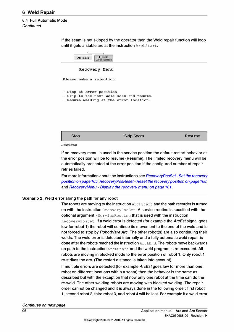
If the seam is not skipped by the operator then the Weld repair function will loopuntil it gets a stable arc at the instruction ArcLStart.
en1300000301
If no recovery menu is used in the service position the default restart behavior atthe error position will be to resume (Resume). The limited recovery menu will beautomatically presented at the error position if the configured number of repairretries failed.For more information about the instructions see RecoveryPosSet - Set the recoveryposition on page165,RecoveryPosReset - Reset the recovery position on page168,and RecoveryMenu - Display the recovery menu on page 161.
Scenario 2: Weld error along the path for any robotThe robots are moving to the instruction ArcLStart and the path recorder is turnedon with the instruction RecoveryPosSet. A service routine is specified with theoptional argument \ServiceRoutine that is used with the instructionRecoveryPosSet. If a weld error is detected (for example the ArcEst signal goeslow for robot 1) the robot will continue its movement to the end of the weld and isnot forced to stop by RobotWare Arc. The other robot(s) are also continuing theirwelds. The weld error is detected internally and a fully automatic weld repair isdone after the robots reached the instruction ArcLEnd. The robots move backwardson path to the instruction ArcLStart and the weld program is re-executed. Allrobots are moving in blocked mode to the error position of robot 1. Only robot 1re-strikes the arc. (The restart distance is taken into account).If multiple errors are detected (for example ArcEst goes low for more than onerobot on different locations within a seam) then the behavior is the same asdescribed but with the exception that now only one robot at the time can do there-weld. The other welding robots are moving with blocked welding. The repairorder cannot be changed and it is always done in the following order: first robot1, second robot 2, third robot 3, and robot 4 will be last. For example if a weld error
Continues on next page96 Application manual - Arc and Arc Sensor
3HAC050988-001 Revision: H© Copyright 2004-2021 ABB. All rights reserved.
6 Weld Repair6.4 Full Automatic ModeContinued

is detected in robot 2 and later along the path for robot 1 then the weld repair forrobot 1 will be done first.If for some reason the re-weld fails again then the robots move backwards on pathinto the service position.
Application manual - Arc and Arc Sensor 973HAC050988-001 Revision: H
© Copyright 2004-2021 ABB. All rights reserved.
6 Weld Repair6.4 Full Automatic Mode
Continued
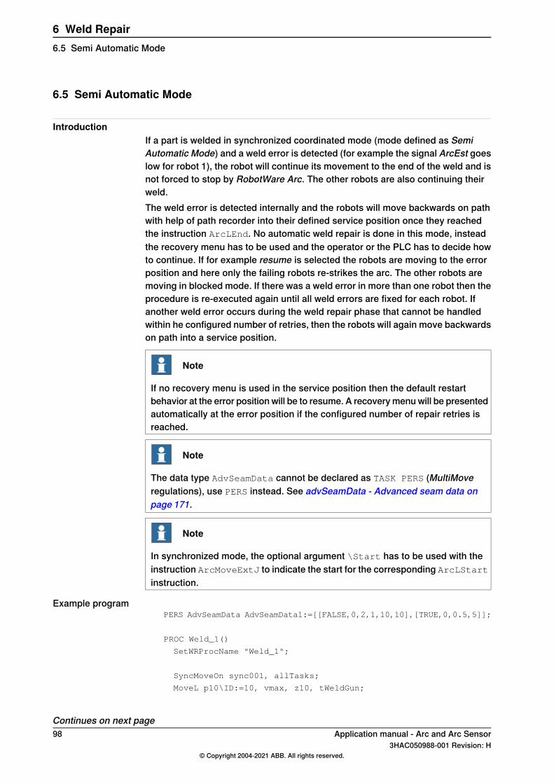
6.5 Semi Automatic Mode
IntroductionIf a part is welded in synchronized coordinated mode (mode defined as SemiAutomatic Mode) and a weld error is detected (for example the signal ArcEst goeslow for robot 1), the robot will continue its movement to the end of the weld and isnot forced to stop by RobotWare Arc. The other robots are also continuing theirweld.The weld error is detected internally and the robots will move backwards on pathwith help of path recorder into their defined service position once they reachedthe instruction ArcLEnd. No automatic weld repair is done in this mode, insteadthe recovery menu has to be used and the operator or the PLC has to decide howto continue. If for example resume is selected the robots are moving to the errorposition and here only the failing robots re-strikes the arc. The other robots aremoving in blocked mode. If there was a weld error in more than one robot then theprocedure is re-executed again until all weld errors are fixed for each robot. Ifanother weld error occurs during the weld repair phase that cannot be handledwithin he configured number of retries, then the robots will again move backwardson path into a service position.
Note
If no recovery menu is used in the service position then the default restartbehavior at the error position will be to resume. A recovery menu will be presentedautomatically at the error position if the configured number of repair retries isreached.
Note
The data type AdvSeamData cannot be declared as TASK PERS (MultiMoveregulations), use PERS instead. See advSeamData - Advanced seam data onpage 171.
Note
In synchronized mode, the optional argument \Start has to be used with theinstruction ArcMoveExtJ to indicate the start for the corresponding ArcLStartinstruction.
Example programPERS AdvSeamData AdvSeamData1:=[[FALSE,0,2,1,10,10],[TRUE,0,0.5,5]];
PROC Weld_1()
SetWRProcName "Weld_1";
SyncMoveOn sync001, allTasks;
MoveL p10\ID:=10, vmax, z10, tWeldGun;
Continues on next page98 Application manual - Arc and Arc Sensor
3HAC050988-001 Revision: H© Copyright 2004-2021 ABB. All rights reserved.
6 Weld Repair6.5 Semi Automatic Mode
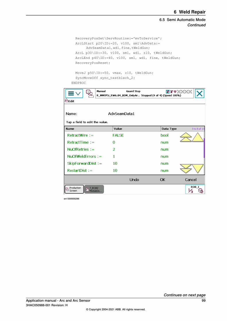
RecoveryPosSet\ServRoutine:="mvToService";
ArcLStart p20\ID:=20, v100, sm1\AdvData:=AdvSeamData1,wd1,fine,tWeldGun;
ArcL p30\ID:=30, v100, sm1, wd1, z10, tWeldGun;
ArcLEnd p40\ID:=40, v100, sm1, wd1, fine, tWeldGun;
RecoveryPosReset;
MoveJ p50\ID:=50, vmax, z10, tWeldGun;
SyncMoveOff sync_testblech_2;
ENDPROC
en1300000296
Continues on next pageApplication manual - Arc and Arc Sensor 993HAC050988-001 Revision: H
© Copyright 2004-2021 ABB. All rights reserved.
6 Weld Repair6.5 Semi Automatic Mode
Continued
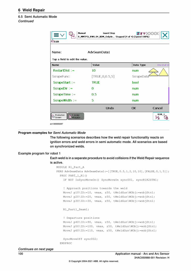
en1300000297
Program examples for Semi Automatic ModeThe following scenarios describes how the weld repair functionality reacts onignition errors and weld errors in semi automatic mode. All scenarios are basedon synchronized welds.
Example program for robot 1Each weld is in a separate procedure to avoid collisions if the Weld Repair sequenceis active.
MODULE R1_Part_A
PERS AdvSeamData AdvSeamData1:=[[TRUE,0.5,1,2,10,10],[FALSE,0,1,5]];
PROC PART_1_R1()
IF NOT IsSyncMoveOn() SyncMoveOn sync001, syncR1R2STN1;
! Approach positions towards the weld
MoveJ p10\ID:=10, vmax, z50, tWeldGun\WObj:=wobjStn1;
MoveJ p20\ID:=20, vmax, z50, tWeldGun\WObj:=wobjStn1;
MoveJ p30\ID:=30, vmax, z50, tWeldGun\WObj:=wobjStn1;
R1_Part1_Seam1;
! Departure positions
MoveJ p40\ID:=90, vmax, z50, tWeldGun\WObj:=wobjStn1;
MoveJ p50\ID:=100, vmax, z50, tWeldGun\WObj:=wobjStn1;
MoveJ p60\ID:=110, vmax, z50, tWeldGun\WObj:=wobjStn1;
SyncMoveOff sync002;
ENDPROC
Continues on next page100 Application manual - Arc and Arc Sensor
3HAC050988-001 Revision: H© Copyright 2004-2021 ABB. All rights reserved.
6 Weld Repair6.5 Semi Automatic ModeContinued
PROC R1_Part1_Seam1()
! Define which procedure shall be re-executed
SetWRProcName "R1_Part1_Seam1";
IF NOT IsSyncMoveOn() SyncMoveOn sync001, syncR1R2STN1;
! Set Recovery Position, here it will be "p30" from exampleabove
! Turn on PathRecorder
RecoveryPosSet\ServRoutine:="mvToService";
ArcLStart pArc10\ID:=40, vmax, sm1\AdvData:=AdvSeamData1, wd1,fine, tWeldGun\WObj:=wobjStn1\SeamName:="R1_Part1_Seam1";
ArcL pArc20\ID:=50, v100, sm1, wd1, z1, tWeldGun\WObj:=wobjStn1;
ArcL pArc30\ID:=60, v100, sm1, wd1, z1, tWeldGun\WObj:=wobjStn1;
ArcC pArc40, pArc50\ID:=70, v100, sm1, wd1, z1,tWeldGun\WObj:=wobjStn1;
ArcLEnd pArc50\ID:=80, v100, sm1, wd1, fine,tWeldGun\WObj:=wobjStn1;
! Turn off PathRecorder
RecoveryPosReset;
ENDPROC
ENDMODULE
Example program for robot 2Each weld is in a separate procedure to avoid collisions if the Weld Repair sequenceis active.
MODULE R1_Part_A
PERS AdvSeamData AdvSeamData1:=[[TRUE,0.5,1,2,10,10],[FALSE,0,1,5]];
PROC R2_PART1()
IF NOT IsSyncMoveOn() SyncMoveOn sync001, syncR1R2STN1;
! Approach positions towards the weld
MoveJ p10\ID:=10, vmax, z50, tWeldGun\WObj:=wobjStn1;
MoveJ p20\ID:=20, vmax, z50, tWeldGun\WObj:=wobjStn1;
MoveJ p30\ID:=30, vmax, z50, tWeldGun\WObj:=wobjStn1;
R2_Part1_Seam1;
! Departure positions
MoveJ p40\ID:=90, vmax, z50, tWeldGun\WObj:=wobjStn1;
MoveJ p50\ID:=100, vmax, z50,tWeldGun\WObj:=wobjStn1;
MoveJ p60\ID:=110, vmax, z50,tWeldGun\WObj:=wobjStn1;
SyncMoveOff sync002;
ENDPROC
PROC R2_Part1_Seam1()
! Define which procedure shall be re-executed
SetWRProcName "R2_Part1_Seam1";
Continues on next pageApplication manual - Arc and Arc Sensor 1013HAC050988-001 Revision: H
© Copyright 2004-2021 ABB. All rights reserved.
6 Weld Repair6.5 Semi Automatic Mode
Continued
IF NOT IsSyncMoveOn() SyncMoveOn sync001, syncR1R2STN1;
! Set Recovery Position, here it will be "p30" from exampleabove
! Turn on PathRecorder
RecoveryPosSet\ServRoutine:="mvToService";
ArcLStart pArc10\ID:=40, vmax, sm1\AdvData:=AdvSeamData1, wd1,fine, tWeldGun\WObj:=wobjStn1\SeamName:="R2_Part1_Seam1";
ArcL pArc20\ID:=50, v100, sm1, wd1, z1, tWeldGun\WObj:=wobjStn1;
ArcL pArc30\ID:=60, v100, sm1, wd1, z1, tWeldGun\WObj:=wobjStn1;
ArcC pArc40, pArc50\ID:=70, v100, sm1, wd1, z1,tWeldGun\WObj:=wobjStn1;
ArcLEnd pArc60\ID:=80, v100, sm1, wd1, fine,tWeldGun\WObj:=wobjStn1;
! Turn off PathRecorder
RecoveryPosReset;
ENDPROC
ENDMODULE
Example program for STN1Each weld is in a separate procedure to avoid collisions if the Weld Repair sequenceis active.
MODULE STN1_Part_A
PROC STN1_Part1()
IF NOT IsMechUnitActive(STN1) ActUnit STN1;
IF NOT IsSyncMoveOn() SyncMoveOn sync001, Alle_STN1;
MoveExtJ p10\ID:=10,vmax,z50;
MoveExtJ p20\ID:=20,vmax,z50;
MoveExtJ p30\ID:=30,vmax,z50;
STN1_Part1_Seam1;
MoveExtJ p40\ID:=90,vmax,z50;
MoveExtJ p50\ID:=100,vmax,z50;
MoveExtJ p60\ID:=110,vmax,z50;
SyncMoveOff sync002;
ENDPROC
PROC STN1_Part1_Seam1()
! Define which procedure shall be re-executed
SetWRProcName "STN1_Part1_Seam1";
IF NOT IsMechUnitActive(STN1) ActUnit STN1;
IF NOT IsSyncMoveOn() SyncMoveOn sync001, Alle_STN1;
! Set Recovery Position, here it will be "p30" from exampleabove
! Turn on PathRecorder
Continues on next page102 Application manual - Arc and Arc Sensor
3HAC050988-001 Revision: H© Copyright 2004-2021 ABB. All rights reserved.
6 Weld Repair6.5 Semi Automatic ModeContinued
RecoveryPosSet\ServRoutine:="mvToService";
! Optional argument "\Start" set to the corresponding ArcLStartinstruction
ArcMoveExtJ pArc10\ID:=40,vmax,fine\Start;
ArcMoveExtJ pArc20\ID:=50,vrot50,z1;
ArcMoveExtJ pArc30\ID:=60,vrot50,z1;
ArcMoveExtJ pArc40\ID:=70,vrot50,z1;
ArcMoveExtJ pArc50\ID:=80,vrot50,fine;
! Turn off PathRecorder
RecoveryPosReset;
ENDPROC
ENDMODULE
Example program for a service routinePROC mvToService()
VAR bool bTaskInSync:=FALSE;
! Check if in synchronized mode
IF IsSyncMoveOn() bTaskInSync:=TRUE;
GetCurrentPosition pEnter\Tool:= tWeldGun \Wobj:=wobj0;
! Suspend synchronization, robots are now in independent mode
IF bTaskInSync SyncMoveSuspend;
IF GetProcErr() THEN
MoveJ pService, v500, fine, tWeldGun\WObj:=wobj0;
RecoveryMenuWR;
ENDIF
! Get synchronized again
IF bTaskInSync SyncMoveResume;
! Move to saved position
IF bTaskInSync THEN
MoveJ pEnter\ID:=200, v500, fine, tWeldGun \WObj:=wobj0;
ELSE
MoveJ pEnter, v500, fine, tWeldGun \WObj:=wobj0;
ENDIF
ENDPROC
Scenario 1: Ignition error at arc start instruction for any robot using advSeamData
The robots are moving to the instruction ArcLStart and the path recorder is turnedon with the instruction RecoveryPosSet. A service routine is specified with theoptional argument \ServiceRoutine that is used with the instructionRecoveryPosSet. Assuming that an ignition error occurs, for example for robot1 and the configured number of retires is exceeded, then the robots will movebackwards on path into their defined recovery position and the specified serviceroutine (in this example mvToService) is executed from here.The synchronization between the robots and positioner can be suspended so thatindividual movements, for example for gun cleaning can be done.
Continues on next pageApplication manual - Arc and Arc Sensor 1033HAC050988-001 Revision: H
© Copyright 2004-2021 ABB. All rights reserved.
6 Weld Repair6.5 Semi Automatic Mode
Continued
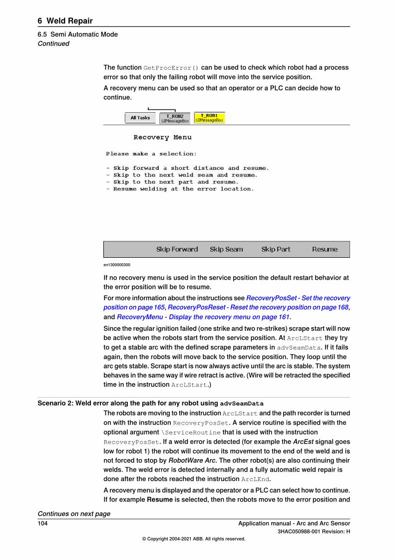
The function GetProcError() can be used to check which robot had a processerror so that only the failing robot will move into the service position.A recovery menu can be used so that an operator or a PLC can decide how tocontinue.
en1300000300
If no recovery menu is used in the service position the default restart behavior atthe error position will be to resume.For more information about the instructions see RecoveryPosSet - Set the recoveryposition on page165,RecoveryPosReset - Reset the recovery position on page168,and RecoveryMenu - Display the recovery menu on page 161.Since the regular ignition failed (one strike and two re-strikes) scrape start will nowbe active when the robots start from the service position. At ArcLStart they tryto get a stable arc with the defined scrape parameters in advSeamData. If it failsagain, then the robots will move back to the service position. They loop until thearc gets stable. Scrape start is now always active until the arc is stable. The systembehaves in the same way if wire retract is active. (Wire will be retracted the specifiedtime in the instruction ArcLStart.)
Scenario 2: Weld error along the path for any robot using advSeamData
The robots are moving to the instruction ArcLStart and the path recorder is turnedon with the instruction RecoveryPosSet. A service routine is specified with theoptional argument \ServiceRoutine that is used with the instructionRecoveryPosSet. If a weld error is detected (for example the ArcEst signal goeslow for robot 1) the robot will continue its movement to the end of the weld and isnot forced to stop by RobotWare Arc. The other robot(s) are also continuing theirwelds. The weld error is detected internally and a fully automatic weld repair isdone after the robots reached the instruction ArcLEnd.A recovery menu is displayed and the operator or a PLC can select how to continue.If for example Resume is selected, then the robots move to the error position and
Continues on next page104 Application manual - Arc and Arc Sensor
3HAC050988-001 Revision: H© Copyright 2004-2021 ABB. All rights reserved.
6 Weld Repair6.5 Semi Automatic ModeContinued
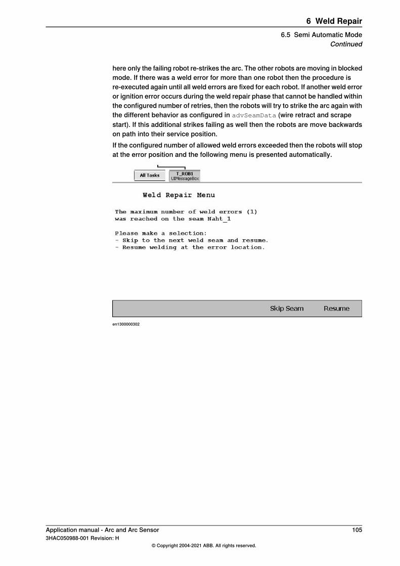
here only the failing robot re-strikes the arc. The other robots are moving in blockedmode. If there was a weld error for more than one robot then the procedure isre-executed again until all weld errors are fixed for each robot. If another weld erroror ignition error occurs during the weld repair phase that cannot be handled withinthe configured number of retries, then the robots will try to strike the arc again withthe different behavior as configured in advSeamData (wire retract and scrapestart). If this additional strikes failing as well then the robots are move backwardson path into their service position.If the configured number of allowed weld errors exceeded then the robots will stopat the error position and the following menu is presented automatically.
en1300000302
Application manual - Arc and Arc Sensor 1053HAC050988-001 Revision: H
© Copyright 2004-2021 ABB. All rights reserved.
6 Weld Repair6.5 Semi Automatic Mode
Continued

This page is intentionally left blank
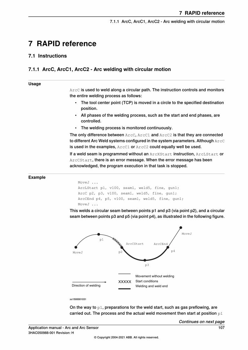
7 RAPID reference7.1 Instructions
7.1.1 ArcC, ArcC1, ArcC2 - Arc welding with circular motion
UsageArcC is used to weld along a circular path. The instruction controls and monitorsthe entire welding process as follows:
• The tool center point (TCP) is moved in a circle to the specified destinationposition.
• All phases of the welding process, such as the start and end phases, arecontrolled.
• The welding process is monitored continuously.The only difference between ArcC, ArcC1 and ArcC2 is that they are connectedto different Arc Weld systems configured in the system parameters. Although ArcCis used in the examples, ArcC1 or ArcC2 could equally well be used.If a weld seam is programmed without an ArcXStart instruction, ArcLStart orArcCStart, there is an error message. When the error message has beenacknowledged, the program execution in that task is stopped.
ExampleMoveJ ...
ArcLStart p1, v100, seam1, weld5, fine, gun1;
ArcC p2, p3, v100, seam1, weld5, fine, gun1;
ArcCEnd p4, p5, v100, seam1, weld5, fine, gun1;
MoveJ ...
This welds a circular seam between points p1 and p3 (via point p2), and a circularseam between points p3 and p5 (via point p4), as illustrated in the following figure.
xxxxx
xxxxxx
MoveJ
ArcCEnd
MoveJ
p1
p2
p3
Movement without welding
Welding and weld endDirection of welding
p4
ArcCStart
Start conditions
xx1500001031
On the way to p1, preparations for the weld start, such as gas preflowing, arecarried out. The process and the actual weld movement then start at position p1
Continues on next pageApplication manual - Arc and Arc Sensor 1073HAC050988-001 Revision: H
© Copyright 2004-2021 ABB. All rights reserved.
7 RAPID reference7.1.1 ArcC, ArcC1, ArcC2 - Arc welding with circular motion
and end at p5. The start and end processes are determined by seam1 and thewelding process by weld5.
ArgumentsArcC CirPoint ToPoint [\ID] Speed Seam Weld [\Weave] Zone Tool
[\WObj] [\Corr] [\Track] [\Time] [\T1] [\T2] [\T3] [\T4] [\T5][\T6] [\T7] [\TLoad]
CirPoint
Data type: robtargetThe circle point of the robot. The circle point is a position on the circle betweenthe start point and the destination point. To obtain the best accuracy, it should beplaced about halfway between the start and destination points. If it is placed tooclose to the start or destination point, the robot may give a warning. The circlepoint is defined as a named position or stored directly in the instruction (markedwith an * in the instruction).
ToPoint
Data type: robtargetThe destination position of the robot and additional axes. This is either defined asa named position or stored directly in the instruction (indicated by an * in theinstruction).
[\ID]
Data type: identnoThe argument [\ID] is mandatory in MultiMove systems, if the movement issynchronized or coordinated synchronized. This argument is not allowed in anyother case. The specified id number must be the same in all the cooperatingprogram tasks. By using the id number the movements are not mixed up at theruntime.
Speed
Data type: speeddataThe speed of the TCP is controlled by the argument Speed in the following cases:
• When the ArcLStart instruction is used.• When the program is run instruction-by-instruction (no welding).
Continues on next page108 Application manual - Arc and Arc Sensor
3HAC050988-001 Revision: H© Copyright 2004-2021 ABB. All rights reserved.
7 RAPID reference7.1.1 ArcC, ArcC1, ArcC2 - Arc welding with circular motionContinued
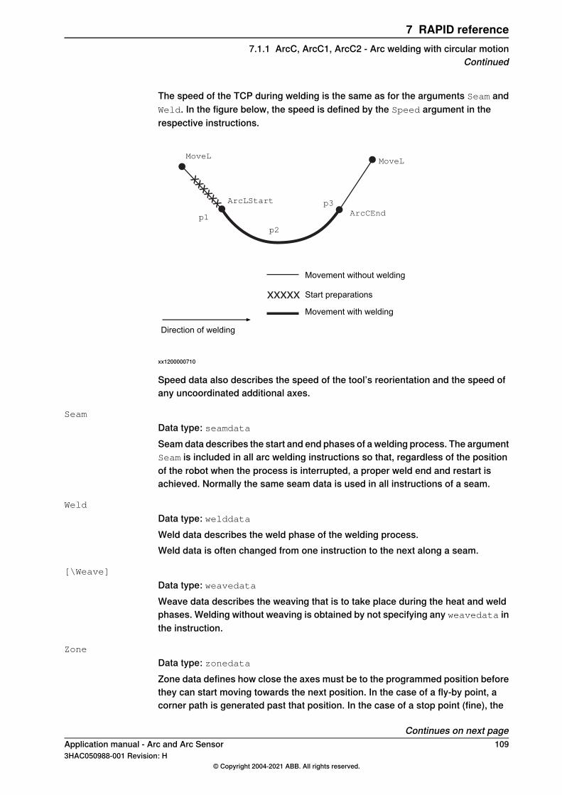
The speed of the TCP during welding is the same as for the arguments Seam andWeld. In the figure below, the speed is defined by the Speed argument in therespective instructions.
xxxxxx
xxxxx
MoveL
ArcLStart
ArcCEnd
MoveL
p1
p2
p3
Movement without welding
Movement with welding
Start preparations
Direction of welding
xx1200000710
Speed data also describes the speed of the tool’s reorientation and the speed ofany uncoordinated additional axes.
Seam
Data type: seamdataSeam data describes the start and end phases of a welding process. The argumentSeam is included in all arc welding instructions so that, regardless of the positionof the robot when the process is interrupted, a proper weld end and restart isachieved. Normally the same seam data is used in all instructions of a seam.
Weld
Data type: welddataWeld data describes the weld phase of the welding process.Weld data is often changed from one instruction to the next along a seam.
[\Weave]
Data type: weavedataWeave data describes the weaving that is to take place during the heat and weldphases. Welding without weaving is obtained by not specifying any weavedata inthe instruction.
Zone
Data type: zonedataZone data defines how close the axes must be to the programmed position beforethey can start moving towards the next position. In the case of a fly-by point, acorner path is generated past that position. In the case of a stop point (fine), the
Continues on next pageApplication manual - Arc and Arc Sensor 1093HAC050988-001 Revision: H
© Copyright 2004-2021 ABB. All rights reserved.
7 RAPID reference7.1.1 ArcC, ArcC1, ArcC2 - Arc welding with circular motion
Continued
movement is interrupted until all axes have reached the programmed point. A stoppoint is always generated automatically at the start position of a weld and at acontrolled weld end position. Fly-by points, such as z10, should be used for allother weld positions. Weld data changes over to the next arc welding instructionat the center point of the corner path.
Tool
Data type: tooldataThe tool used in the movement. The TCP of the tool is the point moved to thespecified destination position. The z-axis of the tool should be parallel with thetorch.
[\WObj]
Data type: wobjdataThe work object (coordinate system) to which the instruction’s robot position isreferenced. When this argument is omitted, the robot position is referenced to theworld coordinate system. It must, however, be specified if a stationary TCP orcoordinated additional axes are used.\WObj can be used if a coordinate system is defined for either the object in questionor the weld seam.
[\Corr]
Data type: switchCorrection data written to a corrections entry by the instruction CorrWrite will beadded to the path and destination position, if this argument is present.The RobotWare option Path Offset is required when using this argument.
[\Track]
Data type: trackdataTrackdata is used and is only applicable when the system is configured for seamtracking with a serial weld guide system or with a Laser Tracker system. Seamtracking is activated when this argument is included in the ArcC instruction, butdeactivated if it is omitted. The optional trackdata argument must be used duringthe whole weldseam, that is, from the ArcXStart to the ArcXEnd instruction.
Note
Seam tracking requires the Optical tracking or WeldGuide options.
[\Time]
Data type: numThis argument is used to specify the total time in seconds during which the robotand additional axes move. It is then substituted for the corresponding speed data.
[\T1] [\T2] [\T3] [\T4] [\T5] [\T6] [\T7]
Data type: triggdata
Continues on next page110 Application manual - Arc and Arc Sensor
3HAC050988-001 Revision: H© Copyright 2004-2021 ABB. All rights reserved.
7 RAPID reference7.1.1 ArcC, ArcC1, ArcC2 - Arc welding with circular motionContinued
Variables that refer to trigger conditions and trigger activity, defined earlier in theprogram using the instructions TriggRampAO, TriggIO, TriggEquip orTriggInt.
[\TLoad]
Data type: loaddataThe \TLoad argument describes the total load used in the movement. The totalload is the tool load together with the payload that the tool is carrying. If the \TLoadargument is used, then the loaddata in the current tooldata is not considered.If the \TLoad argument is set to load0, then the \TLoad argument is not consideredand the loaddata in the current tooldata is used instead. For a completedescription of the \TLoad argument, see MoveL - Moves the robot linearly.
Program execution
Controlling process equipmentThe process equipment is controlled by the robot in such a way that the entireprocess and each of its phases are coordinated with the robot’s movements.
MotionRobot and additional axes are moved to the destination position as follows:
• The TCP of the tool is moved circularly at a constant programmed speed.When coordinated axes are used, the robot and the coordinated axes aremoved simultaneously, resulting in the programmed path and speed for theTCP relative to the work object.
• The tool is reorientated at even intervals throughout the entire course.• Uncoordinated additional axes are executed at a constant speed which means
that they reach their destination at the same time as the robot axes.If the programmed speed of reorientation or of the additional axes is exceeded,these speeds will be limited, thereby reducing the speed of the TCP.The destination position is referenced to the:
• Specified object coordinate system if the argument \WObj is used;• World coordinate system if the argument \WObj is not used.
LimitationsWhen weaving, the distance between the programmed positions should be longerthan the periodic time of weaving. If the distance is shorter and if there is asignificant change of angle in the path, the weaving pattern will be distorted.The instruction ArcC should never be restarted after the circle point has beenpassed. Otherwise the robot will not take the programmed path (positioning aroundthe circular path in another direction compared with that programmed).
Continues on next pageApplication manual - Arc and Arc Sensor 1113HAC050988-001 Revision: H
© Copyright 2004-2021 ABB. All rights reserved.
7 RAPID reference7.1.1 ArcC, ArcC1, ArcC2 - Arc welding with circular motion
Continued
Error handlingThe process is supervised by a number of signal inputs. If anything abnormal isdetected, program execution will stop. If, however, an error handler is programmed,the errors defined below can be remedied without stopping production. See theexample in the instruction RestoPath.
DescriptionError constant (ERRNO value)
Start condition error; torch, gas or water supervisionAW_START_ERR
Ignition error; arc supervisionAW_IGNI_ERR
Weld error; arc supervisionAW_WELD_ERR
Weld equipment error; voltage, current, water or gassupervision during welding
AW_EQIP_ERR
Wire stick error; wire stick supervisionAW_WIRE_ERR
Welding interrupted using the stop process inputAW_STOP_ERR
The process supervision is determined by a part of the process equipmentconfiguration.At the start of the process the robot checks that the following preconditions havebeen met, that is, the following signals are set as follows (see Defining arc weldingsystems on page 202):
• Stop process: low• Water supervision: high• Gas supervision: high• Torch supervision: high
If, after the start command is given, no approved start profile is indicated on thedigital input, arc_OK, within a predetermined time period, the process start will beinterrupted. When the process is started, all supervision inputs selected - such asstop process, water supervision, gas supervision, arc supervision, volt supervision,current supervision, wire supervision - are monitored continuously.The wirestick status is checked at the start and end of the weld. Wirestick errorsare non-recoverable. That is, the welding process and motion can not be resumeduntil the wirestick error is corrected.
Note
Only supervision errors resulting in the error constants AW_IGNI_ERR andAW_WELD_ERR will have automatic retries (if configured). The other errorconstants are considered non-recoverable. On AW_WIRE_ERR there will be noautomatic MoveOut movement (if configured). In a multimove system, whenrunning synchronized welding, there will be no automatic MoveOut movement(if configured) in any of the synchronized robots, if there is an active wirestickerror in any of the synchronized robots.
ExampleMoveL ...
ArcLStart *,v100, seam1, weld5 \Weave:=weave1,fine,gun1\Wobj:=wobj1;
Continues on next page112 Application manual - Arc and Arc Sensor
3HAC050988-001 Revision: H© Copyright 2004-2021 ABB. All rights reserved.
7 RAPID reference7.1.1 ArcC, ArcC1, ArcC2 - Arc welding with circular motionContinued
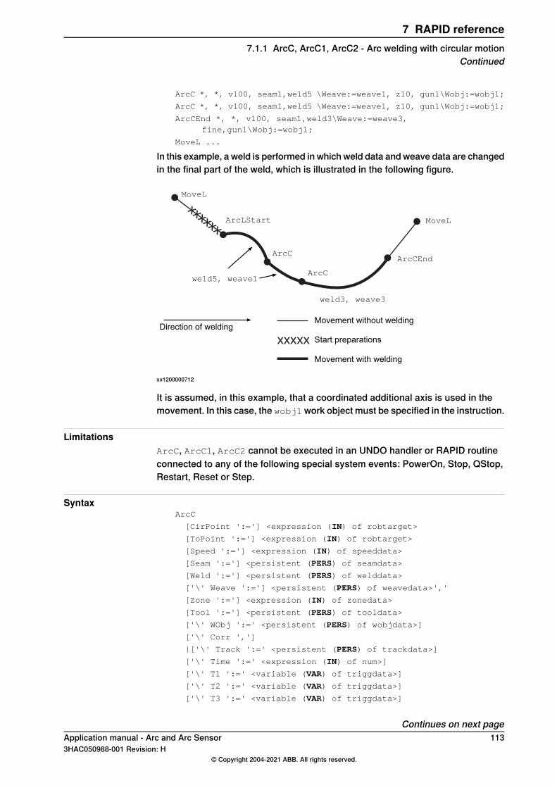
ArcC *, *, v100, seam1,weld5 \Weave:=weave1, z10, gun1\Wobj:=wobj1;
ArcC *, *, v100, seam1,weld5 \Weave:=weave1, z10, gun1\Wobj:=wobj1;
ArcCEnd *, *, v100, seam1,weld3\Weave:=weave3,fine,gun1\Wobj:=wobj1;
MoveL ...
In this example, a weld is performed in which weld data and weave data are changedin the final part of the weld, which is illustrated in the following figure.
xxxxxx
xxxxx
MoveL
ArcLStart
ArcCEnd
MoveL
weld5, weave1
weld3, weave3
ArcC
Movement without welding
Movement with welding
Start preparationsDirection of welding
ArcC
xx1200000712
It is assumed, in this example, that a coordinated additional axis is used in themovement. In this case, the wobj1work object must be specified in the instruction.
LimitationsArcC, ArcC1, ArcC2 cannot be executed in an UNDO handler or RAPID routineconnected to any of the following special system events: PowerOn, Stop, QStop,Restart, Reset or Step.
SyntaxArcC
[CirPoint ':='] <expression (IN) of robtarget>
[ToPoint ':='] <expression (IN) of robtarget>
[Speed ':='] <expression (IN) of speeddata>
[Seam ':='] <persistent (PERS) of seamdata>
[Weld ':='] <persistent (PERS) of welddata>
['\' Weave ':='] <persistent (PERS) of weavedata>','
[Zone ':='] <expression (IN) of zonedata>
[Tool ':='] <persistent (PERS) of tooldata>
['\' WObj ':=' <persistent (PERS) of wobjdata>]
['\' Corr ',']
|['\' Track ':=' <persistent (PERS) of trackdata>]
['\' Time ':=' <expression (IN) of num>]
['\' T1 ':=' <variable (VAR) of triggdata>]
['\' T2 ':=' <variable (VAR) of triggdata>]
['\' T3 ':=' <variable (VAR) of triggdata>]
Continues on next pageApplication manual - Arc and Arc Sensor 1133HAC050988-001 Revision: H
© Copyright 2004-2021 ABB. All rights reserved.
7 RAPID reference7.1.1 ArcC, ArcC1, ArcC2 - Arc welding with circular motion
Continued
['\' T4 ':=' <variable (VAR) of triggdata>]
['\' T5 ':=' <variable (VAR) of triggdata>]
['\' T6 ':=' <variable (VAR) of triggdata>]
['\' T7 ':=' <variable (VAR) of triggdata>]
['\' TLoad':='] <persistent (PERS) of loaddata>]';'
Related information
Described inInformation
ArcL, ArcL1, ArcL2 - Arc welding with linearmotion on page 132
Performing a linear weld
Technical reference manual - RAPID Over-view
Other positioning instructions
Technical referencemanual - RAPID Instruc-tions, Functions and Data types
Definition of speed, speeddata
Technical referencemanual - RAPID Instruc-tions, Functions and Data types
Definition of zone data, zonedata
Technical referencemanual - RAPID Instruc-tions, Functions and Data types
Definition of tools, tooldata
Technical referencemanual - RAPID Instruc-tions, Functions and Data types
Definition of work objects, wobjdata
Technical referencemanual - RAPID Instruc-tions, Functions and Data types
MoveL
Technical referencemanual - RAPID Instruc-tions, Functions and Data types
Definition of loads, loaddata
seamdata - Seam data on page 177Definition of seam data
welddata - Weld data on page 196Definition of weld data
weavedata - Weave data on page 189Definition of weave data
System parameters on page 201Installation parameters for welding equipmentand welding functions
Technical reference manual - RAPID Over-view
Movements in general
Technical reference manual - RAPID Over-view
Coordinate systems
Programming on page 21Process phases and sub-activities
Applicationmanual - Controller software IRC5Path Offset
114 Application manual - Arc and Arc Sensor3HAC050988-001 Revision: H
© Copyright 2004-2021 ABB. All rights reserved.
7 RAPID reference7.1.1 ArcC, ArcC1, ArcC2 - Arc welding with circular motionContinued
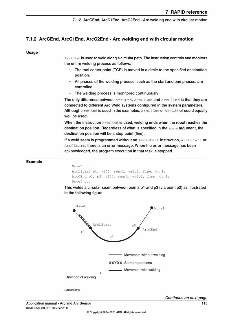
7.1.2 ArcCEnd, ArcC1End, ArcC2End - Arc welding end with circular motion
UsageArcCEnd is used to weld along a circular path. The instruction controls and monitorsthe entire welding process as follows:
• The tool center point (TCP) is moved in a circle to the specified destinationposition.
• All phases of the welding process, such as the start and end phases, arecontrolled.
• The welding process is monitored continuously.The only difference between ArcCEnd, ArcC1End and ArcC2End is that they areconnected to different Arc Weld systems configured in the system parameters.Although ArcCEnd is used in the examples, ArcC1End or ArcC2End could equallywell be used.When the instruction ArcCEnd is used, welding ends when the robot reaches thedestination position. Regardless of what is specified in the Zone argument, thedestination position will be a stop point (fine).If a weld seam is programmed without an ArcXStart instruction, ArcLStart orArcCStart, there is an error message. When the error message has beenacknowledged, the program execution in that task is stopped.
ExampleMoveL ...
ArcLStart p1, v100, seam1, weld5, fine, gun1;
ArcCEnd p2, p3, v100, seam1, weld5, fine, gun1;
MoveL ...
This welds a circular seam between points p1 and p3 (via point p2) as illustratedin the following figure.
xxxxxx
xxxxx
MoveL
ArcLStart
ArcCEnd
MoveL
p1
p2
p3
Movement without welding
Movement with welding
Start preparations
Direction of welding
xx1200000710
Continues on next pageApplication manual - Arc and Arc Sensor 1153HAC050988-001 Revision: H
© Copyright 2004-2021 ABB. All rights reserved.
7 RAPID reference7.1.2 ArcCEnd, ArcC1End, ArcC2End - Arc welding end with circular motion
On the way to p1, preparations for the weld start, such as gas preflowing, arecarried out. The process and the actual weld movement then start at position p1
and end at p3. The start and end processes are determined by seam1 and thewelding process by weld5.
ArgumentsArcCEnd CirPoint ToPoint [\ID] Speed Seam Weld [\Weave] Zone Tool
[\WObj] [\Corr] [\Track] [\Time] [\T1] [\T2] [\T3] [\T4] [\T5][\T6] [\T7] [\TLoad]
CirPoint
Data type: robtargetThe circle point of the robot. The circle point is a position on the circle betweenthe start point and the destination point. To obtain the best accuracy, it should beplaced about halfway between the start and destination points. If it is placed tooclose to the start or destination point, the robot may give a warning. The circlepoint is defined as a named position or stored directly in the instruction (markedwith an * in the instruction).
ToPoint
Data type: robtargetThe destination position of the robot and additional axes. This is either defined asa named position or stored directly in the instruction (indicated by an * in theinstruction).
[\ID]
Data type: identnoThe argument [ \ID ] is mandatory in MultiMove systems, if the movement issynchronized or coordinated synchronized. This argument is not allowed in anyother case. The specified id number must be the same in all the cooperatingprogram tasks. By using the id number the movements are not mixed up at theruntime.
Speed
Data type: speeddataThe speed of the TCP is controlled by the argument Speed in the following cases:
• When the ArcCStart instruction is used.• When the program is run instruction-by-instruction (no welding).
Continues on next page116 Application manual - Arc and Arc Sensor
3HAC050988-001 Revision: H© Copyright 2004-2021 ABB. All rights reserved.
7 RAPID reference7.1.2 ArcCEnd, ArcC1End, ArcC2End - Arc welding end with circular motionContinued
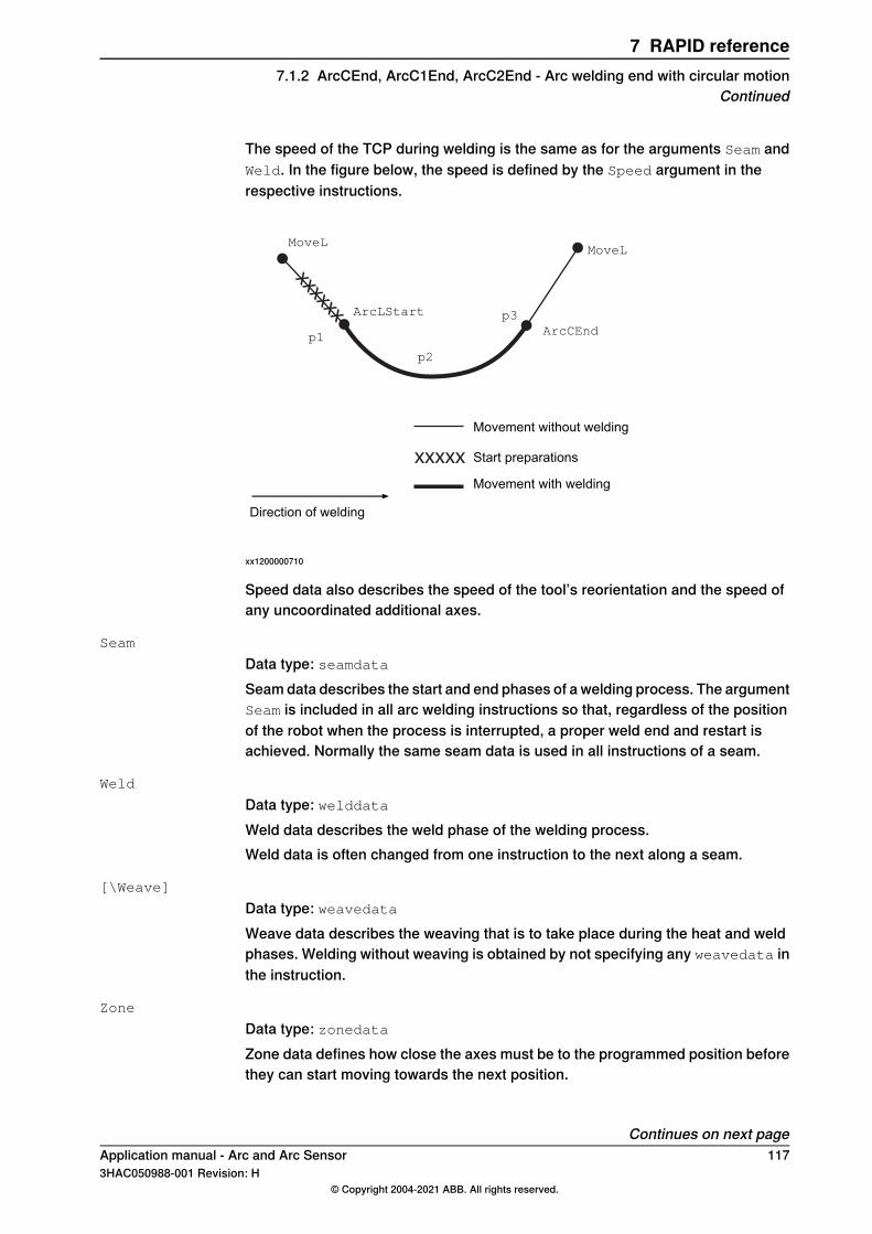
The speed of the TCP during welding is the same as for the arguments Seam andWeld. In the figure below, the speed is defined by the Speed argument in therespective instructions.
xxxxxx
xxxxx
MoveL
ArcLStart
ArcCEnd
MoveL
p1
p2
p3
Movement without welding
Movement with welding
Start preparations
Direction of welding
xx1200000710
Speed data also describes the speed of the tool’s reorientation and the speed ofany uncoordinated additional axes.
Seam
Data type: seamdataSeam data describes the start and end phases of a welding process. The argumentSeam is included in all arc welding instructions so that, regardless of the positionof the robot when the process is interrupted, a proper weld end and restart isachieved. Normally the same seam data is used in all instructions of a seam.
Weld
Data type: welddataWeld data describes the weld phase of the welding process.Weld data is often changed from one instruction to the next along a seam.
[\Weave]
Data type: weavedataWeave data describes the weaving that is to take place during the heat and weldphases. Welding without weaving is obtained by not specifying any weavedata inthe instruction.
Zone
Data type: zonedataZone data defines how close the axes must be to the programmed position beforethey can start moving towards the next position.
Continues on next pageApplication manual - Arc and Arc Sensor 1173HAC050988-001 Revision: H
© Copyright 2004-2021 ABB. All rights reserved.
7 RAPID reference7.1.2 ArcCEnd, ArcC1End, ArcC2End - Arc welding end with circular motion
Continued
In the case of a fly-by point, a corner path is generated past that position. In thecase of a stop point (fine), the movement is interrupted until all axes have reachedthe programmed point.A stop point (fine) is always generated automatically at the start position of a weldand at a controlled weld end position. Fly-by points, such as z10, should be usedfor all other weld positions.Weld data changes over to the next arc welding instruction at the center point ofthe corner path.
Tool
Data type: tooldataThe tool used in the movement. The TCP of the tool is the point moved to thespecified destination position. The z-axis of the tool should be parallel with thetorch.
[\WObj]
Data type: wobjdataThe work object (coordinate system) to which the instruction’s robot position isreferenced. When this argument is omitted, the robot position is referenced to theworld coordinate system. It must, however, be specified if a stationary TCP orcoordinated additional axes are used.\WObj can be used if a coordinate system is defined for either the object in questionor the weld seam.
[\Corr]
Data type: switchCorrection data written to a corrections entry by the instruction CorrWrite will beadded to the path and destination position, if this argument is present.The RobotWare option Path Offset is required when using this argument.
[\Track]
Data type: trackdataTrackdata is used and is only applicable when the system is configured for seamtracking with a serial weld guide system or with a Laser Tracker system. Seamtracking is activated when this argument is included in the ArcC instruction, butdeactivated if it is omitted. The optional trackdata argument must be used duringthe whole weldseam, that is, from the ArcXStart to the ArcXEnd instruction.
Note
Seam tracking requires the Optical tracking or WeldGuide options.
[\Time]
Data type: numThis argument is used to specify the total time in seconds during which the robotand additional axes move. It is then substituted for the corresponding speed data.
Continues on next page118 Application manual - Arc and Arc Sensor
3HAC050988-001 Revision: H© Copyright 2004-2021 ABB. All rights reserved.
7 RAPID reference7.1.2 ArcCEnd, ArcC1End, ArcC2End - Arc welding end with circular motionContinued
[\T1] [\T2] [\T3] [\T4] [\T5] [\T6] [\T7]
Data type: triggdataVariables that refer to trigger conditions and trigger activity, defined earlier in theprogram using the instructionsTriggRampAO, TriggIO, TriggEquip or TriggInt.
[\TLoad]
Data type: loaddataThe \TLoad argument describes the total load used in the movement. The totalload is the tool load together with the payload that the tool is carrying. If the \TLoadargument is used, then the loaddata in the current tooldata is not considered.If the \TLoad argument is set to load0, then the \TLoad argument is not consideredand the loaddata in the current tooldata is used instead. For a completedescription of the \TLoad argument, see MoveL - Moves the robot linearly.
Program execution
Controlling process equipmentThe process equipment is controlled by the robot in such a way that the entireprocess and each of its phases are coordinated with the robot’s movements.
MotionRobot and additional axes are moved to the destination position as follows:
• The TCP of the tool is moved circularly at a constant programmed speed.When coordinated axes are used, the robot and the coordinated axes aremoved simultaneously, resulting in the programmed path and speed for theTCP relative to the work object.
• The tool is reorientated at even intervals throughout the entire course.• Uncoordinated additional axes are executed at a constant speed which means
that they reach their destination at the same time as the robot axes.If the programmed speed of reorientation or of the additional axes is exceeded,these speeds will be limited, thereby reducing the speed of the TCP.The destination position is referenced to the:
• Specified object coordinate system if the argument \WObj is used;• World coordinate system if the argument \WObj is not used.
LimitationsWhen weaving, the distance between the programmed positions should be longerthan the periodic time of weaving. If the distance is shorter and if there is asignificant change of angle in the path, the weaving pattern will be distorted.The instruction ArcC should never be restarted after the circle point has beenpassed. Otherwise the robot will not take the programmed path (positioning aroundthe circular path in another direction compared with that programmed).
Continues on next pageApplication manual - Arc and Arc Sensor 1193HAC050988-001 Revision: H
© Copyright 2004-2021 ABB. All rights reserved.
7 RAPID reference7.1.2 ArcCEnd, ArcC1End, ArcC2End - Arc welding end with circular motion
Continued
Error handlingThe process is supervised by a number of signal inputs. If anything abnormal isdetected, program execution will stop. If, however, an error handler is programmed,the errors defined below can be remedied without stopping production. See theexample in the instruction RestoPath.
DescriptionError constant (ERRNO value)
Start condition error; torch, gas or water supervisionAW_START_ERR
Ignition error; arc supervisionAW_IGNI_ERR
Weld error; arc supervisionAW_WELD_ERR
Weld equipment error; voltage, current, water or gassupervision during welding
AW_EQIP_ERR
Wire stick error; wire stick supervisionAW_WIRE_ERR
Welding interrupted using the stop process inputAW_STOP_ERR
The process supervision is determined by a part of the process equipmentconfiguration.At the start of the process the robot checks that the following preconditions havebeen met, that is, the following signals are set as follows (see Defining arc weldingsystems on page 202):
• Stop process: low• Water supervision: high• Gas supervision: high• Torch supervision: high
If, after the start command is given, no approved start profile is indicated on thedigital input, arc_OK, within a predetermined time period, the process start will beinterrupted. When the process is started, all supervision inputs selected - such asstop process, water supervision, gas supervision, arc supervision, volt supervision,current supervision, wire supervision - are monitored continuously.The wirestick status is checked at the start and end of the weld.Wirestick errors are non-recoverable. That is, the welding process and motion cannot be resumed until the wirestick error is corrected.
Note
Only supervision errors resulting in the error constants AW_IGNI_ERR andAW_WELD_ERR will have automatic retries (if configured). The other errorconstants are considered non-recoverable. On AW_WIRE_ERR there will be noautomatic MoveOut movement (if configured). In a multimove system, whenrunning synchronized welding, there will be no automatic MoveOut movement(if configured) in any of the synchronized robots, if there is an active wirestickerror in any of the synchronized robots.
ExampleMoveL ...
ArcLStart *,v100, seam1, weld5 \Weave:=weave1,fine,gun1\Wobj:=wobj1;
Continues on next page120 Application manual - Arc and Arc Sensor
3HAC050988-001 Revision: H© Copyright 2004-2021 ABB. All rights reserved.
7 RAPID reference7.1.2 ArcCEnd, ArcC1End, ArcC2End - Arc welding end with circular motionContinued
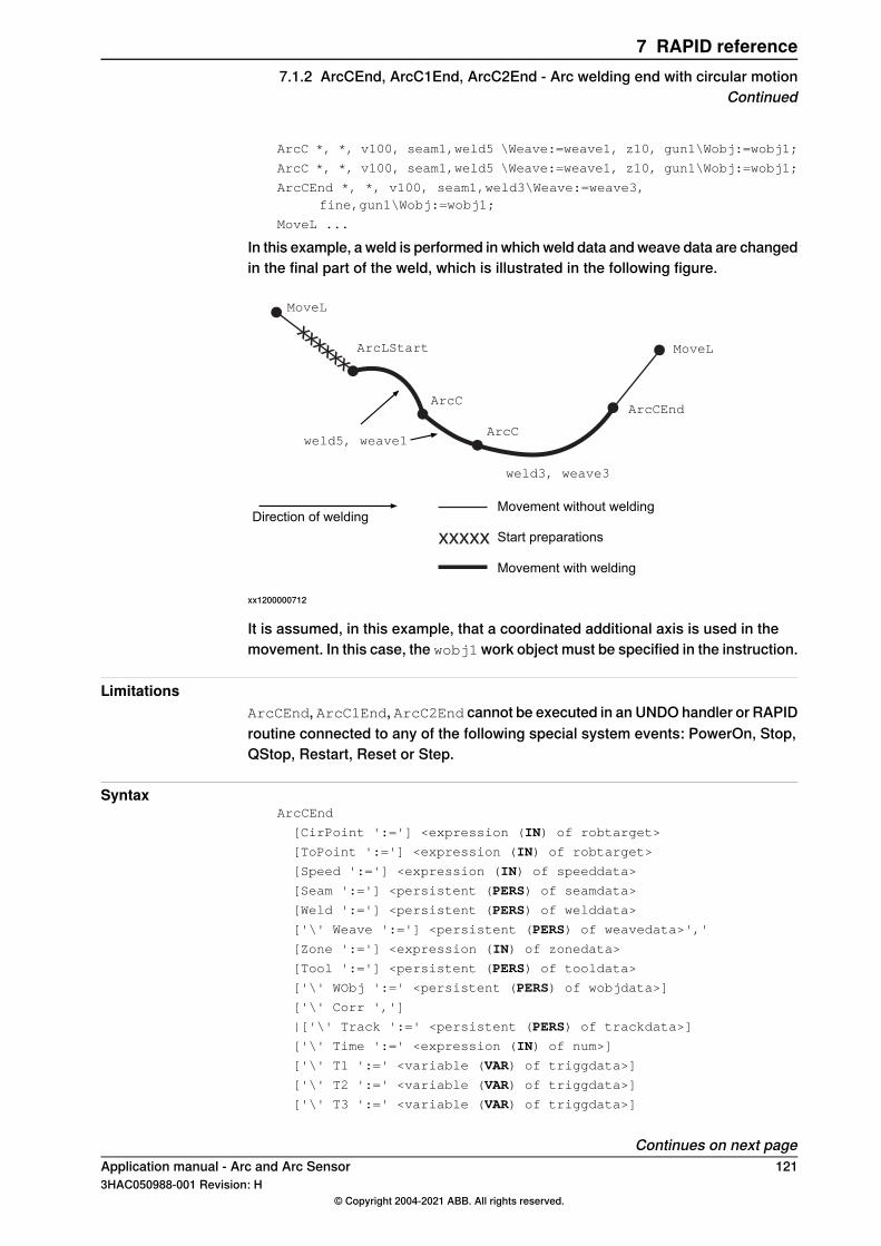
ArcC *, *, v100, seam1,weld5 \Weave:=weave1, z10, gun1\Wobj:=wobj1;
ArcC *, *, v100, seam1,weld5 \Weave:=weave1, z10, gun1\Wobj:=wobj1;
ArcCEnd *, *, v100, seam1,weld3\Weave:=weave3,fine,gun1\Wobj:=wobj1;
MoveL ...
In this example, a weld is performed in which weld data and weave data are changedin the final part of the weld, which is illustrated in the following figure.
xxxxxx
xxxxx
MoveL
ArcLStart
ArcCEnd
MoveL
weld5, weave1
weld3, weave3
ArcC
Movement without welding
Movement with welding
Start preparationsDirection of welding
ArcC
xx1200000712
It is assumed, in this example, that a coordinated additional axis is used in themovement. In this case, the wobj1work object must be specified in the instruction.
LimitationsArcCEnd, ArcC1End, ArcC2End cannot be executed in an UNDO handler or RAPIDroutine connected to any of the following special system events: PowerOn, Stop,QStop, Restart, Reset or Step.
SyntaxArcCEnd
[CirPoint ':='] <expression (IN) of robtarget>
[ToPoint ':='] <expression (IN) of robtarget>
[Speed ':='] <expression (IN) of speeddata>
[Seam ':='] <persistent (PERS) of seamdata>
[Weld ':='] <persistent (PERS) of welddata>
['\' Weave ':='] <persistent (PERS) of weavedata>','
[Zone ':='] <expression (IN) of zonedata>
[Tool ':='] <persistent (PERS) of tooldata>
['\' WObj ':=' <persistent (PERS) of wobjdata>]
['\' Corr ',']
|['\' Track ':=' <persistent (PERS) of trackdata>]
['\' Time ':=' <expression (IN) of num>]
['\' T1 ':=' <variable (VAR) of triggdata>]
['\' T2 ':=' <variable (VAR) of triggdata>]
['\' T3 ':=' <variable (VAR) of triggdata>]
Continues on next pageApplication manual - Arc and Arc Sensor 1213HAC050988-001 Revision: H
© Copyright 2004-2021 ABB. All rights reserved.
7 RAPID reference7.1.2 ArcCEnd, ArcC1End, ArcC2End - Arc welding end with circular motion
Continued
['\' T4 ':=' <variable (VAR) of triggdata>]
['\' T5 ':=' <variable (VAR) of triggdata>]
['\' T6 ':=' <variable (VAR) of triggdata>]
['\' T7 ':=' <variable (VAR) of triggdata>]
['\' TLoad ':='] <persistent (PERS) of loaddata>]';'
Related information
Described inInformation
ArcL, ArcL1, ArcL2 - Arc welding with linearmotion on page 132
Performing a linear weld
Technical reference manual - RAPID Over-view
Other positioning instructions
Technical referencemanual - RAPID Instruc-tions, Functions and Data types
Definition of speed, speeddata
Technical referencemanual - RAPID Instruc-tions, Functions and Data types
Definition of zone data, zonedata
Technical referencemanual - RAPID Instruc-tions, Functions and Data types
Definition of tools, tooldata
Technical referencemanual - RAPID Instruc-tions, Functions and Data types
Definition of work objects, wobjdata
Technical referencemanual - RAPID Instruc-tions, Functions and Data types
MoveL
Technical referencemanual - RAPID Instruc-tions, Functions and Data types
Definition of loads, loaddata
seamdata - Seam data on page 177Definition of seam data
welddata - Weld data on page 196Definition of weld data
weavedata - Weave data on page 189Definition of weave data
System parameters on page 201Installation parameters for welding equipmentand welding functions
Technical reference manual - RAPID Over-view
Movements in general
Technical reference manual - RAPID Over-view
Coordinate systems
Programming on page 21Process phases and sub-activities
Applicationmanual - Controller software IRC5Path Offset
122 Application manual - Arc and Arc Sensor3HAC050988-001 Revision: H
© Copyright 2004-2021 ABB. All rights reserved.
7 RAPID reference7.1.2 ArcCEnd, ArcC1End, ArcC2End - Arc welding end with circular motionContinued
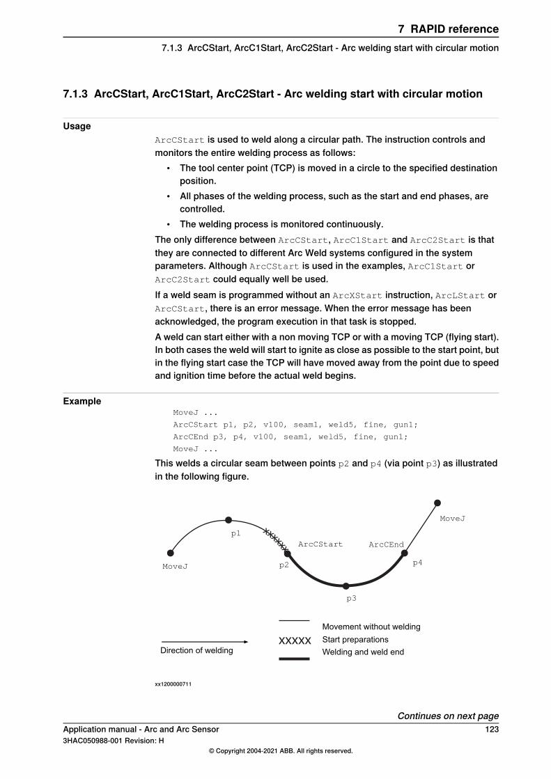
7.1.3 ArcCStart, ArcC1Start, ArcC2Start - Arc welding start with circular motion
UsageArcCStart is used to weld along a circular path. The instruction controls andmonitors the entire welding process as follows:
• The tool center point (TCP) is moved in a circle to the specified destinationposition.
• All phases of the welding process, such as the start and end phases, arecontrolled.
• The welding process is monitored continuously.The only difference between ArcCStart, ArcC1Start and ArcC2Start is thatthey are connected to different Arc Weld systems configured in the systemparameters. Although ArcCStart is used in the examples, ArcC1Start orArcC2Start could equally well be used.If a weld seam is programmed without an ArcXStart instruction, ArcLStart orArcCStart, there is an error message. When the error message has beenacknowledged, the program execution in that task is stopped.A weld can start either with a non moving TCP or with a moving TCP (flying start).In both cases the weld will start to ignite as close as possible to the start point, butin the flying start case the TCP will have moved away from the point due to speedand ignition time before the actual weld begins.
ExampleMoveJ ...
ArcCStart p1, p2, v100, seam1, weld5, fine, gun1;
ArcCEnd p3, p4, v100, seam1, weld5, fine, gun1;
MoveJ ...
This welds a circular seam between points p2 and p4 (via point p3) as illustratedin the following figure.
xxxxx
xxxxxx
MoveJ
ArcCEnd
MoveJ
p1
p2
p3
Movement without welding
Welding and weld endDirection of welding
p4
ArcCStart
Start preparations
xx1200000711
Continues on next pageApplication manual - Arc and Arc Sensor 1233HAC050988-001 Revision: H
© Copyright 2004-2021 ABB. All rights reserved.
7 RAPID reference7.1.3 ArcCStart, ArcC1Start, ArcC2Start - Arc welding start with circular motion
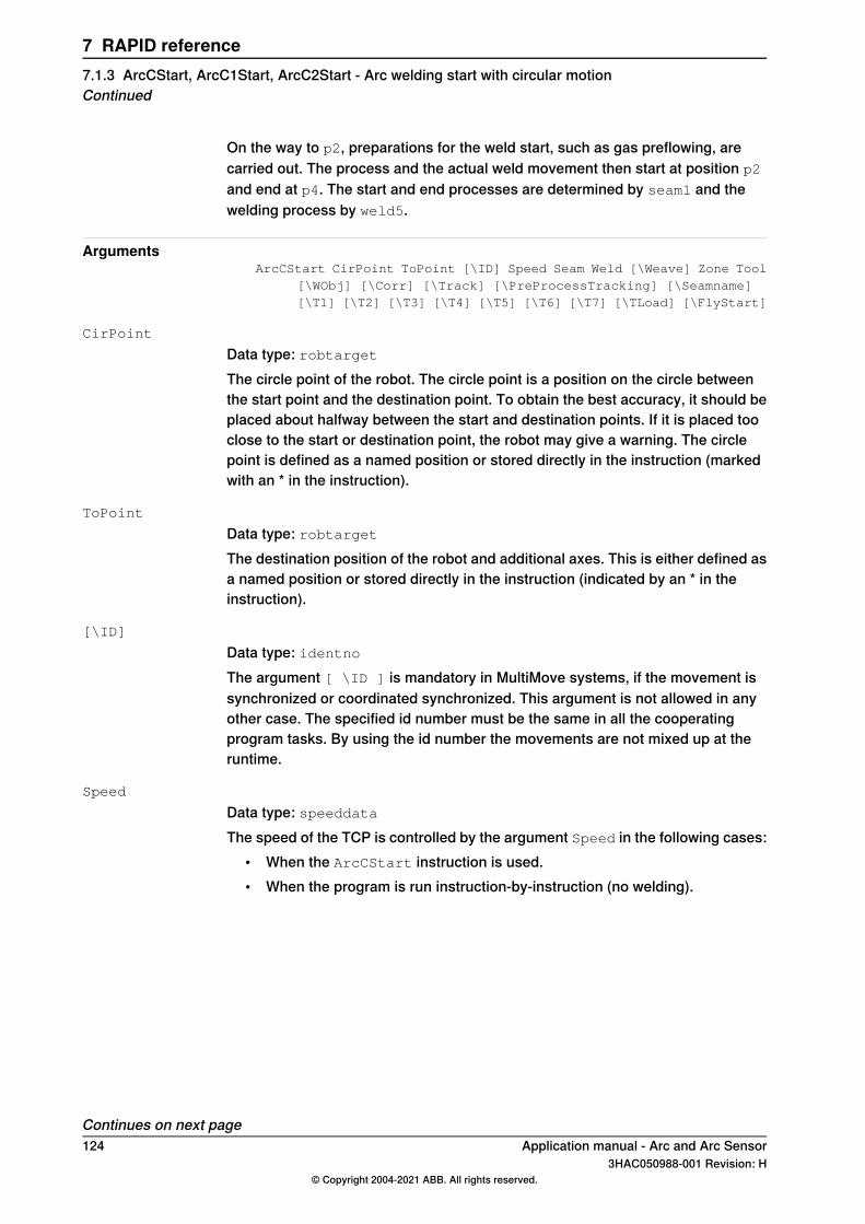
On the way to p2, preparations for the weld start, such as gas preflowing, arecarried out. The process and the actual weld movement then start at position p2
and end at p4. The start and end processes are determined by seam1 and thewelding process by weld5.
ArgumentsArcCStart CirPoint ToPoint [\ID] Speed Seam Weld [\Weave] Zone Tool
[\WObj] [\Corr] [\Track] [\PreProcessTracking] [\Seamname][\T1] [\T2] [\T3] [\T4] [\T5] [\T6] [\T7] [\TLoad] [\FlyStart]
CirPoint
Data type: robtargetThe circle point of the robot. The circle point is a position on the circle betweenthe start point and the destination point. To obtain the best accuracy, it should beplaced about halfway between the start and destination points. If it is placed tooclose to the start or destination point, the robot may give a warning. The circlepoint is defined as a named position or stored directly in the instruction (markedwith an * in the instruction).
ToPoint
Data type: robtargetThe destination position of the robot and additional axes. This is either defined asa named position or stored directly in the instruction (indicated by an * in theinstruction).
[\ID]
Data type: identnoThe argument [ \ID ] is mandatory in MultiMove systems, if the movement issynchronized or coordinated synchronized. This argument is not allowed in anyother case. The specified id number must be the same in all the cooperatingprogram tasks. By using the id number the movements are not mixed up at theruntime.
Speed
Data type: speeddataThe speed of the TCP is controlled by the argument Speed in the following cases:
• When the ArcCStart instruction is used.• When the program is run instruction-by-instruction (no welding).
Continues on next page124 Application manual - Arc and Arc Sensor
3HAC050988-001 Revision: H© Copyright 2004-2021 ABB. All rights reserved.
7 RAPID reference7.1.3 ArcCStart, ArcC1Start, ArcC2Start - Arc welding start with circular motionContinued
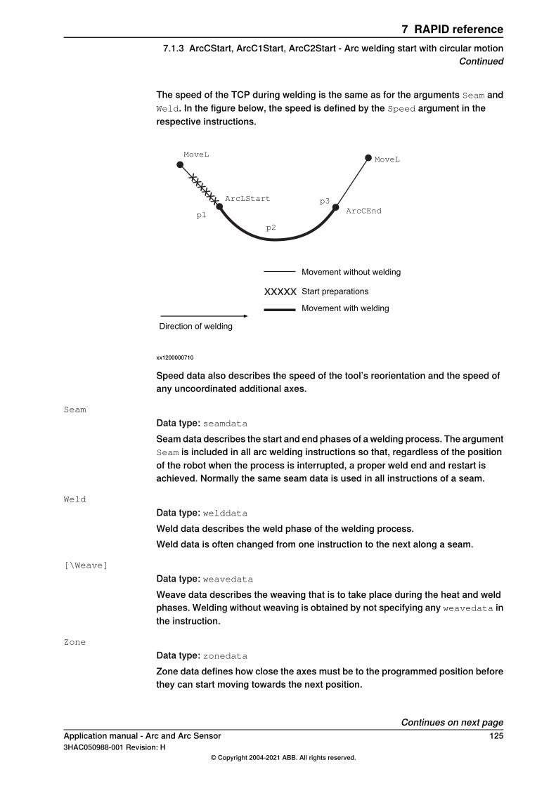
The speed of the TCP during welding is the same as for the arguments Seam andWeld. In the figure below, the speed is defined by the Speed argument in therespective instructions.
xxxxxx
xxxxx
MoveL
ArcLStart
ArcCEnd
MoveL
p1
p2
p3
Movement without welding
Movement with welding
Start preparations
Direction of welding
xx1200000710
Speed data also describes the speed of the tool’s reorientation and the speed ofany uncoordinated additional axes.
Seam
Data type: seamdataSeam data describes the start and end phases of a welding process. The argumentSeam is included in all arc welding instructions so that, regardless of the positionof the robot when the process is interrupted, a proper weld end and restart isachieved. Normally the same seam data is used in all instructions of a seam.
Weld
Data type: welddataWeld data describes the weld phase of the welding process.Weld data is often changed from one instruction to the next along a seam.
[\Weave]
Data type: weavedataWeave data describes the weaving that is to take place during the heat and weldphases. Welding without weaving is obtained by not specifying any weavedata inthe instruction.
Zone
Data type: zonedataZone data defines how close the axes must be to the programmed position beforethey can start moving towards the next position.
Continues on next pageApplication manual - Arc and Arc Sensor 1253HAC050988-001 Revision: H
© Copyright 2004-2021 ABB. All rights reserved.
7 RAPID reference7.1.3 ArcCStart, ArcC1Start, ArcC2Start - Arc welding start with circular motion
Continued
In the case of a fly-by point, a corner path is generated past that position. In thecase of a stop point (fine), the movement is interrupted until all axes have reachedthe programmed point.A stop point (fine) is always generated automatically at the start position of aweld if the parameter \flyStart is not used, and at a controlled weld end position.Fly-by points, such as z10, should be used for all other weld positions.A stop point (fine) is always generated automatically at the start position of aweld and at a controlled weld end position if flying start is deactivated. Fly-bypoints, such as z10, should be used for all other weld positions.If flying start is activated, the start point must be a zone.Weld data changes over to the next arc welding instruction at the center point ofthe corner path.
Tool
Data type: tooldataThe tool used in the movement. The TCP of the tool is the point moved to thespecified destination position. The z-axis of the tool should be parallel with thetorch.
[\WObj]
Data type: wobjdataThe work object (coordinate system) to which the instruction’s robot position isreferenced. When this argument is omitted, the robot position is referenced to theworld coordinate system. It must, however, be specified if a stationary TCP orcoordinated additional axes are used.\WObj can be used if a coordinate system is defined for either the object in questionor the weld seam.
[\Corr]
Data type: switchCorrection data written to a corrections entry by the instruction CorrWrite will beadded to the path and destination position, if this argument is present.The RobotWare option Path Offset is required when using this argument.
[\Track]
Data type: trackdataTrackdata is used and is only applicable when the system is configured for seamtracking with a serial weld guide system or with a Laser Tracker system. Seamtracking is activated when this argument is included in the ArcL instruction, butdeactivated if it is omitted. The optional trackdata argument must be used duringthe whole weldseam, that is, from the ArcXStart to the ArcXEnd instruction.
Note
Seam tracking requires the Optical tracking or WeldGuide options.
Continues on next page126 Application manual - Arc and Arc Sensor
3HAC050988-001 Revision: H© Copyright 2004-2021 ABB. All rights reserved.
7 RAPID reference7.1.3 ArcCStart, ArcC1Start, ArcC2Start - Arc welding start with circular motionContinued
[\PreProcessTracking]
Data type: switchThis argument is effective only if first_instruction is set to TRUE and the\Track argument is present.This argument activates Pre Process Tracking, which means that the robot will betracking only, without process, during that CapX instruction. Thereby sensor dataare available for successful tracking right off the start of the path with process, e.g.welding.For more information see Operating manual - Tracking and searching with opticalsensors.
[\SeamName]
Data type: stringThe seam name is a string which will be added to error logs if an error occursduring the welding sequence. \SeamName is only applicable together with theArcCStart instruction.
[\T1] [\T2] [\T3] [\T4] [\T5] [\T6] [\T7]
Data type: triggdataVariables that refer to trigger conditions and trigger activity, defined earlier in theprogram using the instructionsTriggRampAO, TriggIO, TriggEquip or TriggInt.
[\TLoad]
Data type: loaddataThe \TLoad argument describes the total load used in the movement. The totalload is the tool load together with the payload that the tool is carrying. If the \TLoadargument is used, then the loaddata in the current tooldata is not considered.If the \TLoad argument is set to load0, then the \TLoad argument is not consideredand the loaddata in the current tooldata is used instead. For a completedescription of the \TLoad argument, see MoveL - Moves the robot linearly.
[\FlyStart]
Data type: flystartdataIf the weld shall start with a moving TCP it has to be activated via the parameteractivewithin the flystartdata. The supervision for the ignition is different thanfor a standing still start. If no ignition has occurred within superv_distance fromthe starting zone a supervision error will occur.When using flying start the start point must be a zone.
Program execution
Controlling process equipmentThe process equipment is controlled by the robot in such a way that the entireprocess and each of its phases are coordinated with the robot’s movements.
Continues on next pageApplication manual - Arc and Arc Sensor 1273HAC050988-001 Revision: H
© Copyright 2004-2021 ABB. All rights reserved.
7 RAPID reference7.1.3 ArcCStart, ArcC1Start, ArcC2Start - Arc welding start with circular motion
Continued
MotionRobot and additional axes are moved to the destination position as follows:
• The TCP of the tool is moved circularly at a constant programmed speed.When coordinated axes are used, the robot and the coordinated axes aremoved simultaneously, resulting in the programmed path and speed for theTCP relative to the work object.
• The tool is reorientated at even intervals throughout the entire course.• Uncoordinated additional axes are executed at a constant speed which means
that they reach their destination at the same time as the robot axes.If the programmed speed of reorientation or of the additional axes is exceeded,these speeds will be limited, thereby reducing the speed of the TCP.The destination position is referenced to the:
• Specified object coordinate system if the argument \WObj is used;• World coordinate system if the argument \WObj is not used.
LimitationsWhen weaving, the distance between the programmed positions should be longerthan the periodic time of weaving. If the distance is shorter and if there is asignificant change of angle in the path, the weaving pattern will be distorted.The instruction ArcC should never be restarted after the circle point has beenpassed. Otherwise the robot will not take the programmed path (positioning aroundthe circular path in another direction compared with that programmed).
Flying startWhen using flying start the system will trigger the ignition when the TCP passesthe starting point. The TCP will be moving and it will change to welding speed asclose as possible to the zone centre. Due to the movement the actual position forthe start point of the weld will be some distance away from the starting point. Thatdistance is a result of the welding speed and the ignition time of the actual welder.Flying start cannot be used it in combination with Ignition Movement Delay or aScrape Start. The starting point must be a zone.Flying start ignores the PRE supervision phase. Instead there is a ignitionsupervision distance that is given with the parameter superv_distance. If noignition has occurred within that distance an ignition error will raise.Flying start can be deactivated by setting the parameter active to false. By doingso the start will be treated as a normal weld start with a stopping TCP. The zonepoint will be automatic changed to a stop point (fine).Flying start will not be used when restarting after an ignition error or any otherweld error.
Continues on next page128 Application manual - Arc and Arc Sensor
3HAC050988-001 Revision: H© Copyright 2004-2021 ABB. All rights reserved.
7 RAPID reference7.1.3 ArcCStart, ArcC1Start, ArcC2Start - Arc welding start with circular motionContinued
Error handlingThe process is supervised by a number of signal inputs. If anything abnormal isdetected, program execution will stop. If, however, an error handler is programmed,the errors defined below can be remedied without stopping production. See theexample in the instruction RestoPath.
DescriptionError constant (ERRNO value)
Start condition error; torch, gas or water supervisionAW_START_ERR
Ignition error; arc supervisionAW_IGNI_ERR
Weld error; arc supervisionAW_WELD_ERR
Weld equipment error; voltage, current, water or gassupervision during welding
AW_EQIP_ERR
Wire stick error; wire stick supervisionAW_WIRE_ERR
Welding interrupted using the stop process inputAW_STOP_ERR
The process supervision is determined by a part of the process equipmentconfiguration.At the start of the process the robot checks that the following preconditions havebeen met, that is, the following signals are set as follows (see Defining arc weldingsystems on page 202):
• Stop process: low• Water supervision: high• Gas supervision: high• Torch supervision: high
If, after the start command is given, no approved start profile is indicated on thedigital input, arc_OK, within a predetermined time period, the process start will beinterrupted. When the process is started, all supervision inputs selected - such asstop process, water supervision, gas supervision, arc supervision, volt supervision,current supervision, wire supervision - are monitored continuously.Wirestick errors are non-recoverable. That is, the welding process and motion cannot be resumed until the wirestick error is corrected.
Note
Only supervision errors resulting in the error constants AW_IGNI_ERR andAW_WELD_ERRwill have automatic retries (if configured). The other error constantsare considered non-recoverable. On AW_WIRE_ERR there will be no automaticMoveOut movement (if configured). In a MultiMove system, when runningsynchronized welding, there will be no automatic MoveOut movement (ifconfigured) in any of the synchronized robots, if there is an active wirestick errorin any of the synchronized robots.
ExampleMoveL ...
ArcLStart *,v100, seam1, weld5 \Weave:=weave1,fine,gun1\Wobj:=wobj1;
ArcC *, *, v100, seam1,weld5 \Weave:=weave1, z10, gun1\Wobj:=wobj1;
Continues on next pageApplication manual - Arc and Arc Sensor 1293HAC050988-001 Revision: H
© Copyright 2004-2021 ABB. All rights reserved.
7 RAPID reference7.1.3 ArcCStart, ArcC1Start, ArcC2Start - Arc welding start with circular motion
Continued
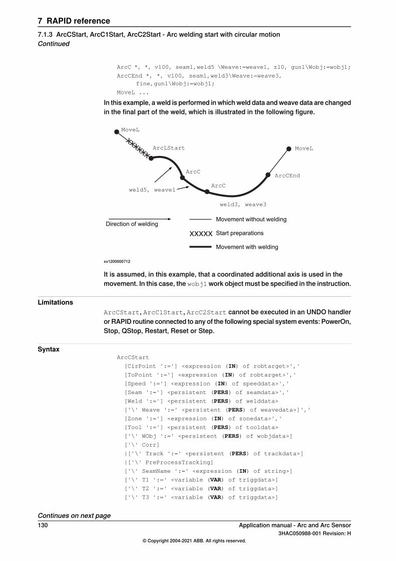
ArcC *, *, v100, seam1,weld5 \Weave:=weave1, z10, gun1\Wobj:=wobj1;
ArcCEnd *, *, v100, seam1,weld3\Weave:=weave3,fine,gun1\Wobj:=wobj1;
MoveL ...
In this example, a weld is performed in which weld data and weave data are changedin the final part of the weld, which is illustrated in the following figure.
xxxxxx
xxxxx
MoveL
ArcLStart
ArcCEnd
MoveL
weld5, weave1
weld3, weave3
ArcC
Movement without welding
Movement with welding
Start preparationsDirection of welding
ArcC
xx1200000712
It is assumed, in this example, that a coordinated additional axis is used in themovement. In this case, the wobj1work object must be specified in the instruction.
LimitationsArcCStart, ArcC1Start, ArcC2Start cannot be executed in an UNDO handleror RAPID routine connected to any of the following special system events: PowerOn,Stop, QStop, Restart, Reset or Step.
SyntaxArcCStart
[CirPoint ':='] <expression (IN) of robtarget>','
[ToPoint ':='] <expression (IN) of robtarget>','
[Speed ':='] <expression (IN) of speeddata>','
[Seam ':='] <persistent (PERS) of seamdata>','
[Weld ':='] <persistent (PERS) of welddata>
['\' Weave ':=' <persistent (PERS) of weavedata>]','
[Zone ':='] <expression (IN) of zonedata>','
[Tool ':='] <persistent (PERS) of tooldata>
['\' WObj ':=' <persistent (PERS) of wobjdata>]
['\' Corr]
|['\' Track ':=' <persistent (PERS) of trackdata>]
|['\' PreProcessTracking]
['\' SeamName ':=' <expression (IN) of string>]
['\' T1 ':=' <variable (VAR) of triggdata>]
['\' T2 ':=' <variable (VAR) of triggdata>]
['\' T3 ':=' <variable (VAR) of triggdata>]
Continues on next page130 Application manual - Arc and Arc Sensor
3HAC050988-001 Revision: H© Copyright 2004-2021 ABB. All rights reserved.
7 RAPID reference7.1.3 ArcCStart, ArcC1Start, ArcC2Start - Arc welding start with circular motionContinued
['\' T4 ':=' <variable (VAR) of triggdata>]
['\' T5 ':=' <variable (VAR) of triggdata>]
['\' T6 ':=' <variable (VAR) of triggdata>]
['\' T7 ':=' <variable (VAR) of triggdata>]
['\' TLoad ':='] <persistent (PERS) of loaddata>]
['\' FlyStart ':='] <persistent (PERS) of flystartdata>]';'
Related information
Described inInformation
ArcL, ArcL1, ArcL2 - Arc welding with linearmotion on page 132
Performing a linear weld
Technical reference manual - RAPID Over-view
Other positioning instructions
Technical referencemanual - RAPID Instruc-tions, Functions and Data types
Definition of speed, speeddata
Technical referencemanual - RAPID Instruc-tions, Functions and Data types
Definition of zone data, zonedata
Technical referencemanual - RAPID Instruc-tions, Functions and Data types
Definition of tools, tooldata
Technical referencemanual - RAPID Instruc-tions, Functions and Data types
Definition of work objects, wobjdata
Technical referencemanual - RAPID Instruc-tions, Functions and Data types
MoveL
Technical referencemanual - RAPID Instruc-tions, Functions and Data types
Definition of loads, loaddata
flystartdata - Flying start data on page 176Definition of flying start data
seamdata - Seam data on page 177Definition of seam data
welddata - Weld data on page 196Definition of weld data
weavedata - Weave data on page 189Definition of weave data
System parameters on page 201Installation parameters for welding equipmentand welding functions
Technical reference manual - RAPID Over-view
Movements in general
Technical reference manual - RAPID Over-view
Coordinate systems
Programming on page 21Process phases and sub-activities
Applicationmanual - Controller software IRC5Path Offset
Operating manual - Tracking and searchingwith optical sensors
Using optical sensors for tracking or search-ing.
Application manual - Arc and Arc Sensor 1313HAC050988-001 Revision: H
© Copyright 2004-2021 ABB. All rights reserved.
7 RAPID reference7.1.3 ArcCStart, ArcC1Start, ArcC2Start - Arc welding start with circular motion
Continued
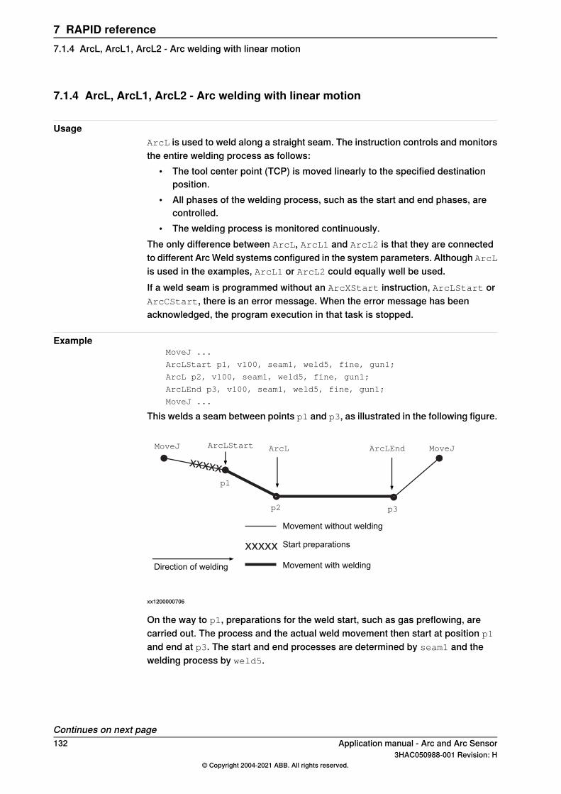
7.1.4 ArcL, ArcL1, ArcL2 - Arc welding with linear motion
UsageArcL is used to weld along a straight seam. The instruction controls and monitorsthe entire welding process as follows:
• The tool center point (TCP) is moved linearly to the specified destinationposition.
• All phases of the welding process, such as the start and end phases, arecontrolled.
• The welding process is monitored continuously.The only difference between ArcL, ArcL1 and ArcL2 is that they are connectedto different Arc Weld systems configured in the system parameters. Although ArcLis used in the examples, ArcL1 or ArcL2 could equally well be used.If a weld seam is programmed without an ArcXStart instruction, ArcLStart orArcCStart, there is an error message. When the error message has beenacknowledged, the program execution in that task is stopped.
ExampleMoveJ ...
ArcLStart p1, v100, seam1, weld5, fine, gun1;
ArcL p2, v100, seam1, weld5, fine, gun1;
ArcLEnd p3, v100, seam1, weld5, fine, gun1;
MoveJ ...
This welds a seam between points p1 and p3, as illustrated in the following figure.
xxxxx
xxxxx
MoveJ ArcL ArcLEnd MoveJ
Movement with weldingDirection of welding
Movement without welding
Start preparations
ArcLStart
p1
p2 p3
xx1200000706
On the way to p1, preparations for the weld start, such as gas preflowing, arecarried out. The process and the actual weld movement then start at position p1
and end at p3. The start and end processes are determined by seam1 and thewelding process by weld5.
Continues on next page132 Application manual - Arc and Arc Sensor
3HAC050988-001 Revision: H© Copyright 2004-2021 ABB. All rights reserved.
7 RAPID reference7.1.4 ArcL, ArcL1, ArcL2 - Arc welding with linear motion
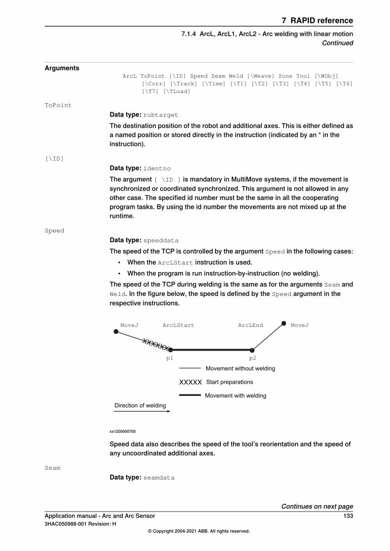
ArgumentsArcL ToPoint [\ID] Speed Seam Weld [\Weave] Zone Tool [\WObj]
[\Corr] [\Track] [\Time] [\T1] [\T2] [\T3] [\T4] [\T5] [\T6][\T7] [\TLoad]
ToPoint
Data type: robtargetThe destination position of the robot and additional axes. This is either defined asa named position or stored directly in the instruction (indicated by an * in theinstruction).
[\ID]
Data type: identnoThe argument [ \ID ] is mandatory in MultiMove systems, if the movement issynchronized or coordinated synchronized. This argument is not allowed in anyother case. The specified id number must be the same in all the cooperatingprogram tasks. By using the id number the movements are not mixed up at theruntime.
Speed
Data type: speeddataThe speed of the TCP is controlled by the argument Speed in the following cases:
• When the ArcLStart instruction is used.• When the program is run instruction-by-instruction (no welding).
The speed of the TCP during welding is the same as for the arguments Seam andWeld. In the figure below, the speed is defined by the Speed argument in therespective instructions.
xxxxxx
xxxxx
MoveJ ArcLStart ArcLEnd MoveJ
p1 p2
Movement without welding
Movement with welding
Start preparations
Direction of welding
xx1200000705
Speed data also describes the speed of the tool’s reorientation and the speed ofany uncoordinated additional axes.
Seam
Data type: seamdata
Continues on next pageApplication manual - Arc and Arc Sensor 1333HAC050988-001 Revision: H
© Copyright 2004-2021 ABB. All rights reserved.
7 RAPID reference7.1.4 ArcL, ArcL1, ArcL2 - Arc welding with linear motion
Continued
Seam data describes the start and end phases of a welding process. The argumentSeam is included in all arc welding instructions so that, regardless of the positionof the robot when the process is interrupted, a proper weld end and restart isachieved. Normally the same seam data is used in all instructions of a seam.
Weld
Data type: welddataWeld data describes the weld phase of the welding process.Weld data is often changed from one instruction to the next along a seam.
[\Weave]
Data type: weavedataWeave data describes the weaving that is to take place during the heat and weldphases. Welding without weaving is obtained by not specifying any weavedata inthe instruction.
Zone
Data type: zonedataZone data defines how close the axes must be to the programmed position beforethey can start moving towards the next position.In the case of a fly-by point, a corner path is generated past that position. In thecase of a stop point (fine), the movement is interrupted until all axes have reachedthe programmed point.A stop point (fine) is always generated automatically at the start position of a weldand at a controlled weld end position. Fly-by points, such as z10, should be usedfor all other weld positions.Weld data changes over to the next arc welding instruction at the center point ofthe corner path.
Tool
Data type: tooldataThe tool used in the movement. The TCP of the tool is the point moved to thespecified destination position. The z-axis of the tool should be parallel with thetorch.
[\WObj]
Data type: wobjdataThe work object (coordinate system) to which the instruction’s robot position isreferenced. When this argument is omitted, the robot position is referenced to theworld coordinate system. It must, however, be specified if a stationary TCP orcoordinated additional axes are used.\WObj can be used if a coordinate system is defined for either the object in questionor the weld seam.
[\Corr]
Data type: switch
Continues on next page134 Application manual - Arc and Arc Sensor
3HAC050988-001 Revision: H© Copyright 2004-2021 ABB. All rights reserved.
7 RAPID reference7.1.4 ArcL, ArcL1, ArcL2 - Arc welding with linear motionContinued
Correction data written to a corrections entry by the instruction CorrWrite will beadded to the path and destination position, if this argument is present.The RobotWare option Path Offset is required when using this argument.
[ \Track]
Data type: trackdataTrackdata is used and is only applicable when the system is configured for seamtracking with a serial weld guide system or with a Laser Tracker system. Seamtracking is activated when this argument is included in the ArcL instruction, butdeactivated if it is omitted. The optional trackdata argument must be used duringthe whole weldseam, that is, from the ArcXStart to the ArcXEnd instruction.
Note
Seam tracking requires the Optical tracking or WeldGuide options.
[ \Time ]
Data type: numThis argument is used to specify the total time in seconds during which the robotand additional axes move. It is then substituted for the corresponding speed data.
[\T1] [\T2] [\T3] [\T4] [\T5] [\T6] [\T7]
Data type: triggdataVariables that refer to trigger conditions and trigger activity, defined earlier in theprogram using the instructionsTriggRampAO, TriggIO, TriggEquip or TriggInt.
[\TLoad]
Data type: loaddataThe \TLoad argument describes the total load used in the movement. The totalload is the tool load together with the payload that the tool is carrying. If the \TLoadargument is used, then the loaddata in the current tooldata is not considered.If the \TLoad argument is set to load0, then the \TLoad argument is not consideredand the loaddata in the current tooldata is used instead. For a completedescription of the \TLoad argument, see MoveL - Moves the robot linearly.
Program execution
Controlling process equipmentThe process equipment is controlled by the robot in such a way that the entireprocess and each of its phases are coordinated with the robot’s movements.
MotionRobot and additional axes are moved to the destination position as follows:
• The TCP of the tool is moved linearly at a constant programmed speed. Whencoordinated axes are used, the robot and the coordinated axes are movedsimultaneously, resulting in the programmed path and speed for the TCPrelative to the work object.
• The tool is reorientated at even intervals throughout the entire course.
Continues on next pageApplication manual - Arc and Arc Sensor 1353HAC050988-001 Revision: H
© Copyright 2004-2021 ABB. All rights reserved.
7 RAPID reference7.1.4 ArcL, ArcL1, ArcL2 - Arc welding with linear motion
Continued
• Uncoordinated additional axes are executed at a constant speed which meansthat they reach their destination at the same time as the robot axes.
If the programmed speed of reorientation or of the additional axes is exceeded,these speeds will be limited, thereby reducing the speed of the TCP.The destination position is referenced to the:
• Specified object coordinate system if the argument \WObj is used;• World coordinate system if the argument \WObj is not used.
LimitationsWhen weaving, the distance between the programmed positions should be longerthan the periodic time of weaving. If the distance is shorter and if there is asignificant change of angle in the path, the weaving pattern will be distorted.Do not use double points, i.e. two consecutive robtargets with the same coordinates(x,y,z) in the same weld. It will result in a short weld process stop with possibleweld defects. When the error occurs, the error message 110003 Arc Supervisionis reported.
Error handlingThe process is supervised by a number of signal inputs. If anything abnormal isdetected, program execution will stop. If, however, an error handler is programmed,the errors defined below can be remedied without stopping production. See theexample in the instruction RestoPath.
DescriptionError constant (ERRNO value)
Start condition error; torch, gas or water supervisionAW_START_ERR
Ignition error; arc supervisionAW_IGNI_ERR
Weld error; arc supervisionAW_WELD_ERR
Weld equipment error; voltage, current, water or gassupervision during welding
AW_EQIP_ERR
Wire stick error; wire stick supervisionAW_WIRE_ERR
Welding interrupted using the stop process inputAW_STOP_ERR
The process supervision is determined by a part of the process equipmentconfiguration.At the start of the process the robot checks that the following preconditions havebeen met, that is, the following signals are set as follows (see Defining arc weldingsystems on page 53):
• Stop process: low• Water supervision: high• Gas supervision: high• Torch supervision: high
If, after the start command is given, no approved start profile is indicated on thedigital input, arc supervision, within a predetermined time period, the process startwill be interrupted. When the process is started, all supervision inputs selected -such as stop process, water supervision, gas supervision, arc supervision, voltsupervision, current supervision, wire supervision - are monitored continuously.
Continues on next page136 Application manual - Arc and Arc Sensor
3HAC050988-001 Revision: H© Copyright 2004-2021 ABB. All rights reserved.
7 RAPID reference7.1.4 ArcL, ArcL1, ArcL2 - Arc welding with linear motionContinued
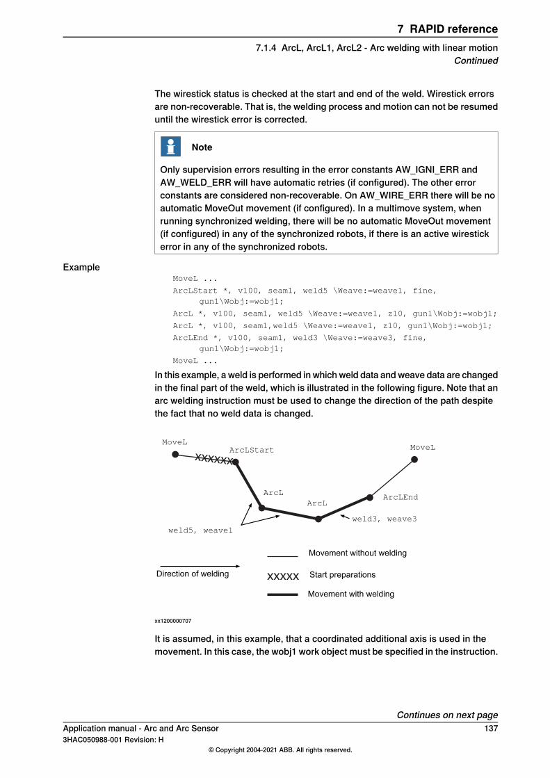
The wirestick status is checked at the start and end of the weld. Wirestick errorsare non-recoverable. That is, the welding process and motion can not be resumeduntil the wirestick error is corrected.
Note
Only supervision errors resulting in the error constants AW_IGNI_ERR andAW_WELD_ERR will have automatic retries (if configured). The other errorconstants are considered non-recoverable. On AW_WIRE_ERR there will be noautomatic MoveOut movement (if configured). In a multimove system, whenrunning synchronized welding, there will be no automatic MoveOut movement(if configured) in any of the synchronized robots, if there is an active wirestickerror in any of the synchronized robots.
ExampleMoveL ...
ArcLStart *, v100, seam1, weld5 \Weave:=weave1, fine,gun1\Wobj:=wobj1;
ArcL *, v100, seam1, weld5 \Weave:=weave1, z10, gun1\Wobj:=wobj1;
ArcL *, v100, seam1,weld5 \Weave:=weave1, z10, gun1\Wobj:=wobj1;
ArcLEnd *, v100, seam1, weld3 \Weave:=weave3, fine,gun1\Wobj:=wobj1;
MoveL ...
In this example, a weld is performed in which weld data and weave data are changedin the final part of the weld, which is illustrated in the following figure. Note that anarc welding instruction must be used to change the direction of the path despitethe fact that no weld data is changed.
xxxxxx
xxxxx
MoveLArcLStart
ArcLEnd
MoveL
weld5, weave1
Movement without welding
Movement with welding
Start preparationsDirection of welding
weld3, weave3
ArcLArcL
xx1200000707
It is assumed, in this example, that a coordinated additional axis is used in themovement. In this case, the wobj1 work object must be specified in the instruction.
Continues on next pageApplication manual - Arc and Arc Sensor 1373HAC050988-001 Revision: H
© Copyright 2004-2021 ABB. All rights reserved.
7 RAPID reference7.1.4 ArcL, ArcL1, ArcL2 - Arc welding with linear motion
Continued
LimitationsArcL, ArcL1, ArcL2 cannot be executed in an UNDO handler or RAPID routineconnected to any of the following special system events: PowerOn, Stop, QStop,Restart, Reset or Step.
SyntaxArcL
[ToPoint ':='] <expression (IN) of robtarget>
[Speed ':='] <expression (IN) of speeddata>
[Seam ':='] <persistent (PERS) of seamdata>
[Weld ':='] <persistent (PERS) of welddata>
['\' Weave ':='] <persistent (PERS) of weavedata>','
[Zone ':='] <expression (IN) of zonedata>
[Tool ':='] <persistent (PERS) of tooldata>
['\' WObj ':=' <persistent (PERS) of wobjdata>]
['\'Corr ',']
|['\' Track ':=' <persistent (PERS) of trackdata>]
['\' Time ':=' <expression (IN) of num>]
['\' T1 ':=' <variable (VAR) of triggdata>]
['\' T2 ':=' <variable (VAR) of triggdata>]
['\' T3 ':=' <variable (VAR) of triggdata>]
['\' T4 ':=' <variable (VAR) of triggdata>]
['\' T5 ':=' <variable (VAR) of triggdata>]
['\' T6 ':=' <variable (VAR) of triggdata>]
['\' T7 ':=' <variable (VAR) of triggdata>]
['\' TLoad ':='] <persistent (PERS) of loaddata>]';'
Related information
Described inInformation
ArcC, ArcC1, ArcC2 - Arc welding with circu-lar motion on page 107
Performing a circular weld
Technical reference manual - RAPID Over-view
Other positioning instructions
Technical referencemanual - RAPID Instruc-tions, Functions and Data types
Definition of speed, speeddata
Technical referencemanual - RAPID Instruc-tions, Functions and Data types
Definition of zone data, zonedata
Technical referencemanual - RAPID Instruc-tions, Functions and Data types
Definition of tools, tooldata
Technical referencemanual - RAPID Instruc-tions, Functions and Data types
Definition of work objects, wobjdata
Technical referencemanual - RAPID Instruc-tions, Functions and Data types
MoveL
Technical referencemanual - RAPID Instruc-tions, Functions and Data types
Definition of loads, loaddata
seamdata - Seam data on page 177Definition of seam data
welddata - Weld data on page 196Definition of weld data
weavedata - Weave data on page 189Definition of weave data
Continues on next page138 Application manual - Arc and Arc Sensor
3HAC050988-001 Revision: H© Copyright 2004-2021 ABB. All rights reserved.
7 RAPID reference7.1.4 ArcL, ArcL1, ArcL2 - Arc welding with linear motionContinued
Described inInformation
System parameters on page 201Installation parameters for welding equipmentand welding functions
Technical reference manual - RAPID Over-view
Movements in general
Technical reference manual - RAPID Over-view
Coordinate systems
Programming for arc welding on page 21Process phases and sub-activities
Applicationmanual - Controller software IRC5Path Offset
Application manual - Arc and Arc Sensor 1393HAC050988-001 Revision: H
© Copyright 2004-2021 ABB. All rights reserved.
7 RAPID reference7.1.4 ArcL, ArcL1, ArcL2 - Arc welding with linear motion
Continued
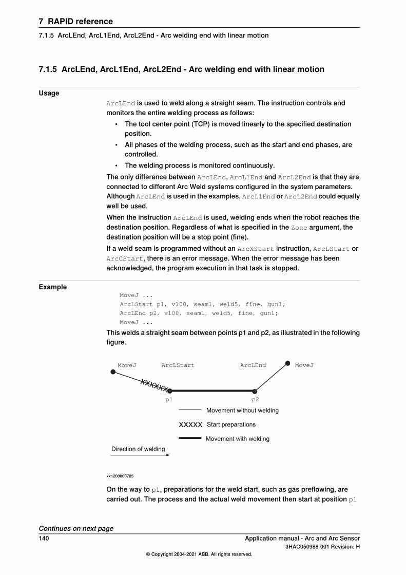
7.1.5 ArcLEnd, ArcL1End, ArcL2End - Arc welding end with linear motion
UsageArcLEnd is used to weld along a straight seam. The instruction controls andmonitors the entire welding process as follows:
• The tool center point (TCP) is moved linearly to the specified destinationposition.
• All phases of the welding process, such as the start and end phases, arecontrolled.
• The welding process is monitored continuously.The only difference between ArcLEnd, ArcL1End and ArcL2End is that they areconnected to different Arc Weld systems configured in the system parameters.Although ArcLEnd is used in the examples, ArcL1End or ArcL2End could equallywell be used.When the instruction ArcLEnd is used, welding ends when the robot reaches thedestination position. Regardless of what is specified in the Zone argument, thedestination position will be a stop point (fine).If a weld seam is programmed without an ArcXStart instruction, ArcLStart orArcCStart, there is an error message. When the error message has beenacknowledged, the program execution in that task is stopped.
ExampleMoveJ ...
ArcLStart p1, v100, seam1, weld5, fine, gun1;
ArcLEnd p2, v100, seam1, weld5, fine, gun1;
MoveJ ...
This welds a straight seam between points p1 and p2, as illustrated in the followingfigure.
xxxxxx
xxxxx
MoveJ ArcLStart ArcLEnd MoveJ
p1 p2
Movement without welding
Movement with welding
Start preparations
Direction of welding
xx1200000705
On the way to p1, preparations for the weld start, such as gas preflowing, arecarried out. The process and the actual weld movement then start at position p1
Continues on next page140 Application manual - Arc and Arc Sensor
3HAC050988-001 Revision: H© Copyright 2004-2021 ABB. All rights reserved.
7 RAPID reference7.1.5 ArcLEnd, ArcL1End, ArcL2End - Arc welding end with linear motion
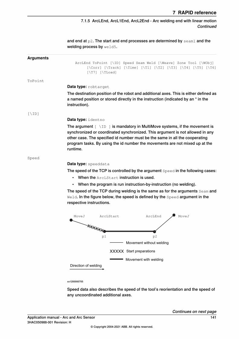
and end at p2. The start and end processes are determined by seam1 and thewelding process by weld5.
ArgumentsArcLEnd ToPoint [\ID] Speed Seam Weld [\Weave] Zone Tool [\WObj]
[\Corr] [\Track] [\Time] [\T1] [\T2] [\T3] [\T4] [\T5] [\T6][\T7] [\TLoad]
ToPoint
Data type: robtargetThe destination position of the robot and additional axes. This is either defined asa named position or stored directly in the instruction (indicated by an * in theinstruction).
[\ID]
Data type: identnoThe argument [ \ID ] is mandatory in MultiMove systems, if the movement issynchronized or coordinated synchronized. This argument is not allowed in anyother case. The specified id number must be the same in all the cooperatingprogram tasks. By using the id number the movements are not mixed up at theruntime.
Speed
Data type: speeddataThe speed of the TCP is controlled by the argument Speed in the following cases:
• When the ArcLStart instruction is used.• When the program is run instruction-by-instruction (no welding).
The speed of the TCP during welding is the same as for the arguments Seam andWeld. In the figure below, the speed is defined by the Speed argument in therespective instructions.
xxxxxx
xxxxx
MoveJ ArcLStart ArcLEnd MoveJ
p1 p2
Movement without welding
Movement with welding
Start preparations
Direction of welding
xx1200000705
Speed data also describes the speed of the tool’s reorientation and the speed ofany uncoordinated additional axes.
Continues on next pageApplication manual - Arc and Arc Sensor 1413HAC050988-001 Revision: H
© Copyright 2004-2021 ABB. All rights reserved.
7 RAPID reference7.1.5 ArcLEnd, ArcL1End, ArcL2End - Arc welding end with linear motion
Continued
Seam
Data type: seamdataSeam data describes the start and end phases of a welding process. The argumentSeam is included in all arc welding instructions so that, regardless of the positionof the robot when the process is interrupted, a proper weld end and restart isachieved. Normally the same seam data is used in all instructions of a seam.
Weld
Data type: welddataWeld data describes the weld phase of the welding process.Weld data is often changed from one instruction to the next along a seam.
[\Weave]
Data type: weavedataWeave data describes the weaving that is to take place during the heat and weldphases. Welding without weaving is obtained by not specifying any weavedata inthe instruction.
Zone
Data type: zonedataZone data defines how close the axes must be to the programmed position beforethey can start moving towards the next position.In the case of a fly-by point, a corner path is generated past that position. In thecase of a stop point (fine), the movement is interrupted until all axes have reachedthe programmed point.A stop point (fine) is always generated automatically at the start position of a weldand at a controlled weld end position. Fly-by points, such as z10, should be usedfor all other weld positions.Weld data changes over to the next arc welding instruction at the center point ofthe corner path.
Tool
Data type: tooldataThe tool used in the movement. The TCP of the tool is the point moved to thespecified destination position. The z-axis of the tool should be parallel with thetorch.
[\WObj]
Data type: wobjdataThe work object (coordinate system) to which the instruction’s robot position isreferenced. When this argument is omitted, the robot position is referenced to theworld coordinate system. It must, however, be specified if a stationary TCP orcoordinated additional axes are used.\WObj can be used if a coordinate system is defined for either the object in questionor the weld seam.
Continues on next page142 Application manual - Arc and Arc Sensor
3HAC050988-001 Revision: H© Copyright 2004-2021 ABB. All rights reserved.
7 RAPID reference7.1.5 ArcLEnd, ArcL1End, ArcL2End - Arc welding end with linear motionContinued
[\Corr]
Data type: switchCorrection data written to a corrections entry by the instruction CorrWrite will beadded to the path and destination position, if this argument is present.The RobotWare option Path Offset is required when using this argument.
[\Track]
Data type: trackdataTrackdata is used and is only applicable when the system is configured for seamtracking with a serial weld guide system or with a Laser Tracker system. Seamtracking is activated when this argument is included in the ArcL instruction, butdeactivated if it is omitted. The optional trackdata argument must be used duringthe whole weldseam, that is, from the ArcXStart to the ArcXEnd instruction.
Note
Seam tracking requires the Optical tracking or WeldGuide options.
[\Time]
Data type: numThis argument is used to specify the total time in seconds during which the robotand additional axes move. It is then substituted for the corresponding speed data.
[\T1] [\T2] [\T3] [\T4] [\T5] [\T6] [\T7]
Data type: triggdataVariables that refer to trigger conditions and trigger activity, defined earlier in theprogram using the instructionsTriggRampAO, TriggIO, TriggEquip or TriggInt.
[\TLoad]
Data type: loaddataThe \TLoad argument describes the total load used in the movement. The totalload is the tool load together with the payload that the tool is carrying. If the \TLoadargument is used, then the loaddata in the current tooldata is not considered.If the \TLoad argument is set to load0, then the \TLoad argument is not consideredand the loaddata in the current tooldata is used instead. For a completedescription of the \TLoad argument, see MoveL - Moves the robot linearly.
Program execution
Controlling process equipmentThe process equipment is controlled by the robot in such a way that the entireprocess and each of its phases are coordinated with the robot’s movements.
MotionRobot and additional axes are moved to the destination position as follows:
• The TCP of the tool is moved linearly at a constant programmed speed. Whencoordinated axes are used, the robot and the coordinated axes are moved
Continues on next pageApplication manual - Arc and Arc Sensor 1433HAC050988-001 Revision: H
© Copyright 2004-2021 ABB. All rights reserved.
7 RAPID reference7.1.5 ArcLEnd, ArcL1End, ArcL2End - Arc welding end with linear motion
Continued
simultaneously, resulting in the programmed path and speed for the TCPrelative to the work object.
• The tool is reorientated at even intervals throughout the entire course.• Uncoordinated additional axes are executed at a constant speed which means
that they reach their destination at the same time as the robot axes.If the programmed speed of reorientation or of the additional axes is exceeded,these speeds will be limited, thereby reducing the speed of the TCP.The destination position is referenced to the:
• Specified object coordinate system if the argument \WObj is used;• World coordinate system if the argument \WObj is not used.
LimitationsWhen weaving, the distance between the programmed positions should be longerthan the periodic time of weaving. If the distance is shorter and if there is asignificant change of angle in the path, the weaving pattern will be distorted.Do not use double points, i.e. two consecutive robtargets with the same coordinates(x,y,z) in the same weld. It will result in a short weld process stop with possibleweld defects. When the error occurs, the error message 110003 Arc Supervisionis reported.
Error handlingThe process is supervised by a number of signal inputs. If anything abnormal isdetected, program execution will stop. If, however, an error handler is programmed,the errors defined below can be remedied without stopping production. See theexample in the instruction RestoPath.
DescriptionError constant (ERRNO value)
Start condition error; torch, gas or water supervisionAW_START_ERR
Ignition error; arc supervisionAW_IGNI_ERR
Weld error; arc supervisionAW_WELD_ERR
Weld equipment error; voltage, current, water or gassupervision during welding
AW_EQIP_ERR
Wire stick error; wire stick supervisionAW_WIRE_ERR
Welding interrupted using the stop process inputAW_STOP_ERR
The process supervision is determined by a part of the process equipmentconfiguration.At the start of the process the robot checks that the following preconditions havebeen met, that is, the following signals are set as follows (see Defining arc weldingsystems on page 53):
• Stop process: low• Water supervision: high• Gas supervision: high• Torch supervision: high
If, after the start command is given, no approved start profile is indicated on thedigital input, arc supervision, within a predetermined time period, the process start
Continues on next page144 Application manual - Arc and Arc Sensor
3HAC050988-001 Revision: H© Copyright 2004-2021 ABB. All rights reserved.
7 RAPID reference7.1.5 ArcLEnd, ArcL1End, ArcL2End - Arc welding end with linear motionContinued
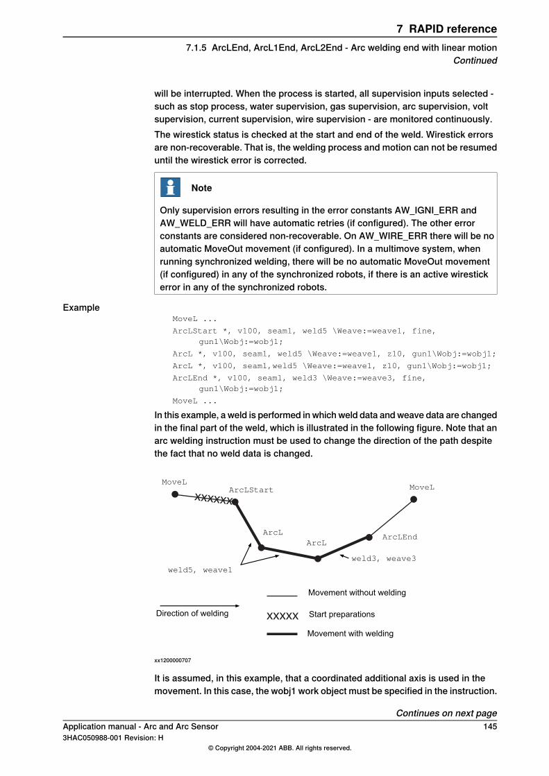
will be interrupted. When the process is started, all supervision inputs selected -such as stop process, water supervision, gas supervision, arc supervision, voltsupervision, current supervision, wire supervision - are monitored continuously.The wirestick status is checked at the start and end of the weld. Wirestick errorsare non-recoverable. That is, the welding process and motion can not be resumeduntil the wirestick error is corrected.
Note
Only supervision errors resulting in the error constants AW_IGNI_ERR andAW_WELD_ERR will have automatic retries (if configured). The other errorconstants are considered non-recoverable. On AW_WIRE_ERR there will be noautomatic MoveOut movement (if configured). In a multimove system, whenrunning synchronized welding, there will be no automatic MoveOut movement(if configured) in any of the synchronized robots, if there is an active wirestickerror in any of the synchronized robots.
ExampleMoveL ...
ArcLStart *, v100, seam1, weld5 \Weave:=weave1, fine,gun1\Wobj:=wobj1;
ArcL *, v100, seam1, weld5 \Weave:=weave1, z10, gun1\Wobj:=wobj1;
ArcL *, v100, seam1,weld5 \Weave:=weave1, z10, gun1\Wobj:=wobj1;
ArcLEnd *, v100, seam1, weld3 \Weave:=weave3, fine,gun1\Wobj:=wobj1;
MoveL ...
In this example, a weld is performed in which weld data and weave data are changedin the final part of the weld, which is illustrated in the following figure. Note that anarc welding instruction must be used to change the direction of the path despitethe fact that no weld data is changed.
xxxxxx
xxxxx
MoveLArcLStart
ArcLEnd
MoveL
weld5, weave1
Movement without welding
Movement with welding
Start preparationsDirection of welding
weld3, weave3
ArcLArcL
xx1200000707
It is assumed, in this example, that a coordinated additional axis is used in themovement. In this case, the wobj1 work object must be specified in the instruction.
Continues on next pageApplication manual - Arc and Arc Sensor 1453HAC050988-001 Revision: H
© Copyright 2004-2021 ABB. All rights reserved.
7 RAPID reference7.1.5 ArcLEnd, ArcL1End, ArcL2End - Arc welding end with linear motion
Continued
LimitationsArcLEnd, ArcL1End, ArcL2End cannot be executed in an UNDO handler or RAPIDroutine connected to any of the following special system events: PowerOn, Stop,QStop, Restart, Reset or Step.
SyntaxArcLEnd
[ToPoint ':='] <expression (IN) of robtarget>
[Speed ':='] <expression (IN) of speeddata>
[Seam ':='] <persistent (PERS) of seamdata>
[Weld ':='] <persistent (PERS) of welddata>
['\' Weave ':='] <persistent (PERS) of weavedata>','
[Zone ':='] <expression (IN) of zonedata>
[Tool ':='] <persistent (PERS) of tooldata>
['\' WObj ':=' <persistent (PERS) of wobjdata>]
['\'Corr ',']
|['\' Track ':=' <persistent (PERS) of trackdata>]
['\' Time ':=' <expression (IN) of num>]
['\' T1 ':=' <variable (VAR) of triggdata>]
['\' T2 ':=' <variable (VAR) of triggdata>]
['\' T3 ':=' <variable (VAR) of triggdata>]
['\' T4 ':=' <variable (VAR) of triggdata>]
['\' T5 ':=' <variable (VAR) of triggdata>]
['\' T6 ':=' <variable (VAR) of triggdata>]
['\' T7 ':=' <variable (VAR) of triggdata>]
['\' TLoad ':='] <persistent (PERS) of loaddata>]';'
Related information
Described inInformation
ArcC, ArcC1, ArcC2 - Arc welding with circu-lar motion on page 107
Performing a circular weld
Technical reference manual - RAPID Over-view
Other positioning instructions
Technical referencemanual - RAPID Instruc-tions, Functions and Data types
Definition of speed, speeddata
Technical referencemanual - RAPID Instruc-tions, Functions and Data types
Definition of zone data, zonedata
Technical referencemanual - RAPID Instruc-tions, Functions and Data types
Definition of tools, tooldata
Technical referencemanual - RAPID Instruc-tions, Functions and Data types
Definition of work objects, wobjdata
Technical referencemanual - RAPID Instruc-tions, Functions and Data types
MoveL
Technical referencemanual - RAPID Instruc-tions, Functions and Data types
Definition of loads, loaddata
seamdata - Seam data on page 177Definition of seam data
welddata - Weld data on page 196Definition of weld data
weavedata - Weave data on page 189Definition of weave data
Continues on next page146 Application manual - Arc and Arc Sensor
3HAC050988-001 Revision: H© Copyright 2004-2021 ABB. All rights reserved.
7 RAPID reference7.1.5 ArcLEnd, ArcL1End, ArcL2End - Arc welding end with linear motionContinued
Described inInformation
System parameters on page 201Installation parameters for welding equipmentand welding functions
Technical reference manual - RAPID Over-view
Movements in general
Technical reference manual - RAPID Over-view
Coordinate systems
Programming on page 21Process phases and sub-activities
Applicationmanual - Controller software IRC5Path Offset
Application manual - Arc and Arc Sensor 1473HAC050988-001 Revision: H
© Copyright 2004-2021 ABB. All rights reserved.
7 RAPID reference7.1.5 ArcLEnd, ArcL1End, ArcL2End - Arc welding end with linear motion
Continued
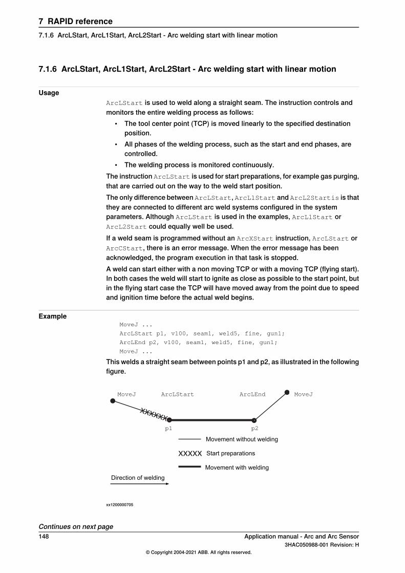
7.1.6 ArcLStart, ArcL1Start, ArcL2Start - Arc welding start with linear motion
UsageArcLStart is used to weld along a straight seam. The instruction controls andmonitors the entire welding process as follows:
• The tool center point (TCP) is moved linearly to the specified destinationposition.
• All phases of the welding process, such as the start and end phases, arecontrolled.
• The welding process is monitored continuously.The instruction ArcLStart is used for start preparations, for example gas purging,that are carried out on the way to the weld start position.The only difference between ArcLStart, ArcL1Start and ArcL2Startis is thatthey are connected to different arc weld systems configured in the systemparameters. Although ArcLStart is used in the examples, ArcL1Start orArcL2Start could equally well be used.If a weld seam is programmed without an ArcXStart instruction, ArcLStart orArcCStart, there is an error message. When the error message has beenacknowledged, the program execution in that task is stopped.A weld can start either with a non moving TCP or with a moving TCP (flying start).In both cases the weld will start to ignite as close as possible to the start point, butin the flying start case the TCP will have moved away from the point due to speedand ignition time before the actual weld begins.
ExampleMoveJ ...
ArcLStart p1, v100, seam1, weld5, fine, gun1;
ArcLEnd p2, v100, seam1, weld5, fine, gun1;
MoveJ ...
This welds a straight seam between points p1 and p2, as illustrated in the followingfigure.
xxxxxx
xxxxx
MoveJ ArcLStart ArcLEnd MoveJ
p1 p2
Movement without welding
Movement with welding
Start preparations
Direction of welding
xx1200000705
Continues on next page148 Application manual - Arc and Arc Sensor
3HAC050988-001 Revision: H© Copyright 2004-2021 ABB. All rights reserved.
7 RAPID reference7.1.6 ArcLStart, ArcL1Start, ArcL2Start - Arc welding start with linear motion
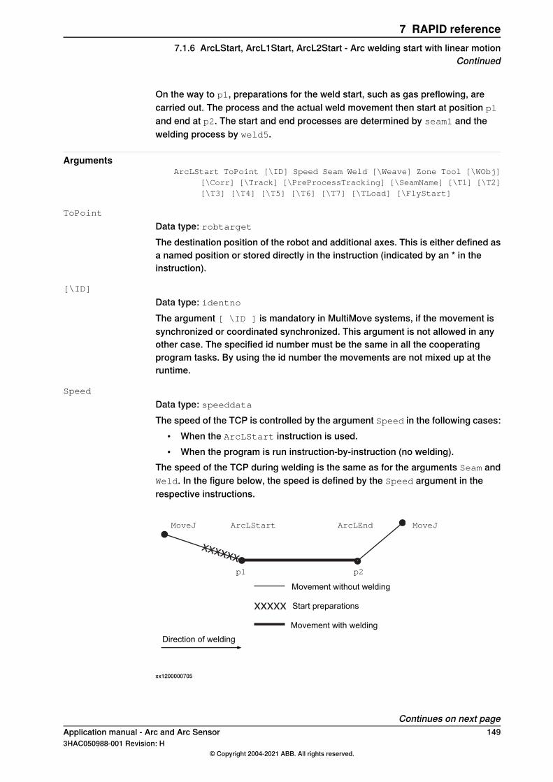
On the way to p1, preparations for the weld start, such as gas preflowing, arecarried out. The process and the actual weld movement then start at position p1
and end at p2. The start and end processes are determined by seam1 and thewelding process by weld5.
ArgumentsArcLStart ToPoint [\ID] Speed Seam Weld [\Weave] Zone Tool [\WObj]
[\Corr] [\Track] [\PreProcessTracking] [\SeamName] [\T1] [\T2][\T3] [\T4] [\T5] [\T6] [\T7] [\TLoad] [\FlyStart]
ToPoint
Data type: robtargetThe destination position of the robot and additional axes. This is either defined asa named position or stored directly in the instruction (indicated by an * in theinstruction).
[\ID]
Data type: identnoThe argument [ \ID ] is mandatory in MultiMove systems, if the movement issynchronized or coordinated synchronized. This argument is not allowed in anyother case. The specified id number must be the same in all the cooperatingprogram tasks. By using the id number the movements are not mixed up at theruntime.
Speed
Data type: speeddataThe speed of the TCP is controlled by the argument Speed in the following cases:
• When the ArcLStart instruction is used.• When the program is run instruction-by-instruction (no welding).
The speed of the TCP during welding is the same as for the arguments Seam andWeld. In the figure below, the speed is defined by the Speed argument in therespective instructions.
xxxxxx
xxxxx
MoveJ ArcLStart ArcLEnd MoveJ
p1 p2
Movement without welding
Movement with welding
Start preparations
Direction of welding
xx1200000705
Continues on next pageApplication manual - Arc and Arc Sensor 1493HAC050988-001 Revision: H
© Copyright 2004-2021 ABB. All rights reserved.
7 RAPID reference7.1.6 ArcLStart, ArcL1Start, ArcL2Start - Arc welding start with linear motion
Continued
Speed data also describes the speed of the tool’s reorientation and the speed ofany uncoordinated additional axes.
Seam
Data type: seamdataSeam data describes the start and end phases of a welding process. The argumentSeam is included in all arc welding instructions so that, regardless of the positionof the robot when the process is interrupted, a proper weld end and restart isachieved. Normally the same seam data is used in all instructions of a seam.
Weld
Data type: welddataWeld data describes the weld phase of the welding process.Weld data is often changed from one instruction to the next along a seam.
[\Weave]
Data type: weavedataWeave data describes the weaving that is to take place during the heat and weldphases. Welding without weaving is obtained by not specifying any weavedata inthe instruction.
Zone
Data type: zonedataZone data defines how close the axes must be to the programmed position beforethey can start moving towards the next position.In the case of a fly-by point, a corner path is generated past that position. In thecase of a stop point (fine), the movement is interrupted until all axes have reachedthe programmed point.A stop point (fine) is always generated automatically at the start position of aweld if the parameter \flyStart is not used, and at a controlled weld end position.Fly-by points, such as z10, should be used for all other weld positions.A stop point (fine) is always generated automatically at the start position of aweld and at a controlled weld end position if flying start is deactivated. Fly-bypoints, such as z10, should be used for all other weld positions.Weld data changes over to the next arc welding instruction at the center point ofthe corner path.
Tool
Data type: tooldataThe tool used in the movement. The TCP of the tool is the point moved to thespecified destination position. The z-axis of the tool should be parallel with thetorch.
[\WObj]
Data type: wobjdataThe work object (coordinate system) to which the instruction’s robot position isreferenced. When this argument is omitted, the robot position is referenced to the
Continues on next page150 Application manual - Arc and Arc Sensor
3HAC050988-001 Revision: H© Copyright 2004-2021 ABB. All rights reserved.
7 RAPID reference7.1.6 ArcLStart, ArcL1Start, ArcL2Start - Arc welding start with linear motionContinued
world coordinate system. It must, however, be specified if a stationary TCP orcoordinated additional axes are used.\WObj can be used if a coordinate system is defined for either the object in questionor the weld seam.
[\Corr]
Data type: switchCorrection data written to a corrections entry by the instruction CorrWrite will beadded to the path and destination position, if this argument is present.The RobotWare option Path Offset is required when using this argument.
[\Track]
Data type: trackdataTrackdata is used and is only applicable when the system is configured for seamtracking with a serial weld guide system or with a Laser Tracker system. Seamtracking is activated when this argument is included in the ArcL instruction, butdeactivated if it is omitted. The optional trackdata argument must be used duringthe whole weldseam, that is, from the ArcXStart to the ArcXEnd instruction.
Note
Seam tracking requires the Optical tracking or WeldGuide options.
[\PreProcessTracking]
Data type: switchThis argument is effective only if first_instruction is set to TRUE and the\Track argument is present.This argument activates Pre Process Tracking, which means that the robot will betracking only, without process, during that CapX instruction. Thereby sensor dataare available for successful tracking right off the start of the path with process, e.g.welding.For more information see Operating manual - Tracking and searching with opticalsensors.
[\SeamName]
Data type: stringThe seam name is a string which will be added to error logs if an error occursduring the welding sequence. \SeamName is only applicable together with theArcLStart instruction.
[\T1] [\T2] [\T3] [\T4] [\T5] [\T6] [\T7]
Data type: triggdataVariables that refer to trigger conditions and trigger activity, defined earlier in theprogram using the instructionsTriggRampAO, TriggIO, TriggEquip or TriggInt.
[\TLoad]
Data type: loaddata
Continues on next pageApplication manual - Arc and Arc Sensor 1513HAC050988-001 Revision: H
© Copyright 2004-2021 ABB. All rights reserved.
7 RAPID reference7.1.6 ArcLStart, ArcL1Start, ArcL2Start - Arc welding start with linear motion
Continued
The \TLoad argument describes the total load used in the movement. The totalload is the tool load together with the payload that the tool is carrying. If the \TLoadargument is used, then the loaddata in the current tooldata is not considered.If the \TLoad argument is set to load0, then the \TLoad argument is not consideredand the loaddata in the current tooldata is used instead. For a completedescription of the \TLoad argument, see MoveL - Moves the robot linearly.
[\FlyStart]
Data type: flystartdataIf the weld shall start with a moving TCP it has to be activated via the parameteractivewithin the flystartdata. The supervision for the ignition is different thanfor a standing still start. If no ignition has occurred within superv_distance fromthe starting zone a supervision error will occur.When using flying start the start point must be a zone.
Program execution
Controlling process equipmentThe process equipment is controlled by the robot in such a way that the entireprocess and each of its phases are coordinated with the robot’s movements.
MotionRobot and additional axes are moved to the destination position as follows:
• The TCP of the tool is moved linearly at a constant programmed speed. Whencoordinated axes are used, the robot and the coordinated axes are movedsimultaneously, resulting in the programmed path and speed for the TCPrelative to the work object.
• The tool is reorientated at even intervals throughout the entire course.• Uncoordinated additional axes are executed at a constant speed which means
that they reach their destination at the same time as the robot axes.If the programmed speed of reorientation or of the additional axes is exceeded,these speeds will be limited, thereby reducing the speed of the TCP.The destination position is referenced to the:
• Specified object coordinate system if the argument \WObj is used;• World coordinate system if the argument \WObj is not used.
LimitationsWhen weaving, the distance between the programmed positions should be longerthan the periodic time of weaving. If the distance is shorter and if there is asignificant change of angle in the path, the weaving pattern will be distorted.Do not use double points, i.e. two consecutive robtargets with the same coordinates(x,y,z) in the same weld. It will result in a short weld process stop with possibleweld defects. When the error occurs, the error message 110003 Arc Supervisionis reported.
Continues on next page152 Application manual - Arc and Arc Sensor
3HAC050988-001 Revision: H© Copyright 2004-2021 ABB. All rights reserved.
7 RAPID reference7.1.6 ArcLStart, ArcL1Start, ArcL2Start - Arc welding start with linear motionContinued
Flying startWhen using flying start the system will trigger the ignition when the TCP passesthe starting point. The TCP will be moving and it will change to welding speed asclose as possible to the zone centre. Due to the movement the actual position forthe start point of the weld will be some distance away from the starting point. Thatdistance is a result of the welding speed and the ignition time of the actual welder.Flying start cannot be used it in combination with Ignition Movement Delay or aScrape Start. The starting point must be a zone.Flying start ignores the PRE supervision phase. Instead there is a ignitionsupervision distance that is given with the parameter superv_distance. If noignition has occurred within that distance an ignition error will raise.Flying start can be deactivated by setting the parameter active to false. By doingso the start will be treated as a normal weld start with a stopping TCP. The zonepoint will be automatic changed to a stop point (fine).Flying start will not be used when restarting after an ignition error or any otherweld error.
Error handlingThe process is supervised by a number of signal inputs. If anything abnormal isdetected, program execution will stop. If, however, an error handler is programmed,the errors defined below can be remedied without stopping production. See theexample in the instruction RestoPath.
DescriptionError constant (ERRNO value)
Start condition error; torch, gas or water supervisionAW_START_ERR
Ignition error; arc supervisionAW_IGNI_ERR
Weld error; arc supervisionAW_WELD_ERR
Weld equipment error; voltage, current, water or gassupervision during welding
AW_EQIP_ERR
Wire stick error; wire stick supervisionAW_WIRE_ERR
Welding interrupted using the stop process inputAW_STOP_ERR
The process supervision is determined by a part of the process equipmentconfiguration.At the start of the process the robot checks that the following preconditions havebeen met, that is, the following signals are set as follows (see Defining arc weldingsystems on page 53):
• Stop process: low• Water supervision: high• Gas supervision: high• Torch supervision: high
If, after the start command is given, no approved start profile is indicated on thedigital input, arc supervision, within a predetermined time period, the process startwill be interrupted. When the process is started, all supervision inputs selected -such as stop process, water supervision, gas supervision, arc supervision, voltsupervision, current supervision, wire supervision - are monitored continuously.
Continues on next pageApplication manual - Arc and Arc Sensor 1533HAC050988-001 Revision: H
© Copyright 2004-2021 ABB. All rights reserved.
7 RAPID reference7.1.6 ArcLStart, ArcL1Start, ArcL2Start - Arc welding start with linear motion
Continued
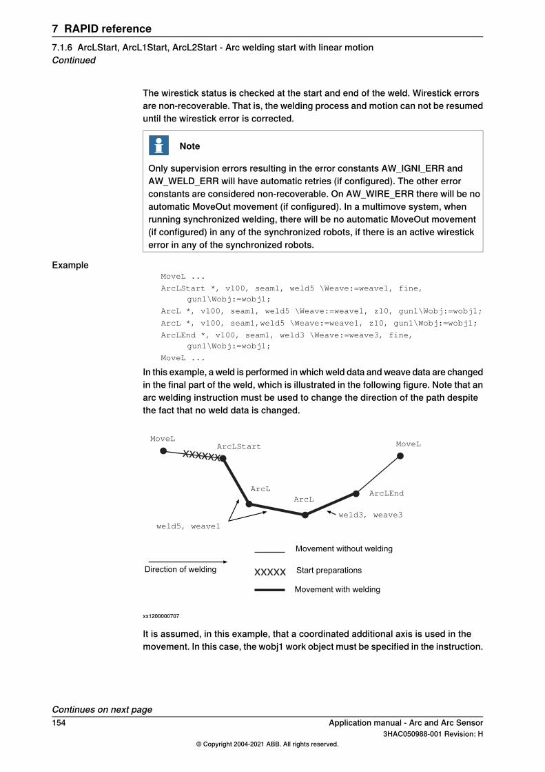
The wirestick status is checked at the start and end of the weld. Wirestick errorsare non-recoverable. That is, the welding process and motion can not be resumeduntil the wirestick error is corrected.
Note
Only supervision errors resulting in the error constants AW_IGNI_ERR andAW_WELD_ERR will have automatic retries (if configured). The other errorconstants are considered non-recoverable. On AW_WIRE_ERR there will be noautomatic MoveOut movement (if configured). In a multimove system, whenrunning synchronized welding, there will be no automatic MoveOut movement(if configured) in any of the synchronized robots, if there is an active wirestickerror in any of the synchronized robots.
ExampleMoveL ...
ArcLStart *, v100, seam1, weld5 \Weave:=weave1, fine,gun1\Wobj:=wobj1;
ArcL *, v100, seam1, weld5 \Weave:=weave1, z10, gun1\Wobj:=wobj1;
ArcL *, v100, seam1,weld5 \Weave:=weave1, z10, gun1\Wobj:=wobj1;
ArcLEnd *, v100, seam1, weld3 \Weave:=weave3, fine,gun1\Wobj:=wobj1;
MoveL ...
In this example, a weld is performed in which weld data and weave data are changedin the final part of the weld, which is illustrated in the following figure. Note that anarc welding instruction must be used to change the direction of the path despitethe fact that no weld data is changed.
xxxxxx
xxxxx
MoveLArcLStart
ArcLEnd
MoveL
weld5, weave1
Movement without welding
Movement with welding
Start preparationsDirection of welding
weld3, weave3
ArcLArcL
xx1200000707
It is assumed, in this example, that a coordinated additional axis is used in themovement. In this case, the wobj1 work object must be specified in the instruction.
Continues on next page154 Application manual - Arc and Arc Sensor
3HAC050988-001 Revision: H© Copyright 2004-2021 ABB. All rights reserved.
7 RAPID reference7.1.6 ArcLStart, ArcL1Start, ArcL2Start - Arc welding start with linear motionContinued
LimitationsArcLStart, ArcL1Start, ArcL2Start cannot be executed in an UNDO handleror RAPID routine connected to any of the following special system events: PowerOn,Stop, QStop, Restart, Reset or Step.
SyntaxArcLStart
[ToPoint ':='] <expression (IN) of robtarget>
[Speed ':='] <expression (IN) of speeddata>','
[Seam ':='] <persistent (PERS) of seamdata>','
[Weld ':='] <persistent (PERS) of welddata>
['\' Weave ':=' <persistent (PERS) of weavedata>]','
[Zone ':='] <expression (IN) of zonedata>','
[Tool ':='] <persistent (PERS) of tooldata>
['\' WObj ':=' <persistent (PERS) of wobjdata>]
['\' Corr]
|['\' Track ':=' <persistent (PERS) of trackdata>]
|['\' PreProcessTracking]
['\' SeamName ':=' <expression (IN) of string>]
['\' T1 ':=' <variable (VAR) of triggdata>]
['\' T2 ':=' <variable (VAR) of triggdata>]
['\' T3 ':=' <variable (VAR) of triggdata>]
['\' T4 ':=' <variable (VAR) of triggdata>]
['\' T5 ':=' <variable (VAR) of triggdata>]
['\' T6 ':=' <variable (VAR) of triggdata>]
['\' T7 ':=' <variable (VAR) of triggdata>]
['\' TLoad ':='] <persistent (PERS) of loaddata>]
['\' FlyStart ':='] <persistent (PERS) of flystartdata>]';'
Related information
Described inInformation
ArcC, ArcC1, ArcC2 - Arc welding with circu-lar motion on page 107
Performing a circular weldzonedata
Technical reference manual - RAPID Over-view
Other positioning instructions
Technical referencemanual - RAPID Instruc-tions, Functions and Data types
Definition of speed, speeddata
Technical referencemanual - RAPID Instruc-tions, Functions and Data types
Definition of zone data, zonedata
Technical referencemanual - RAPID Instruc-tions, Functions and Data types
Definition of tools, tooldata
Technical referencemanual - RAPID Instruc-tions, Functions and Data types
Definition of work objects, wobjdata
Technical referencemanual - RAPID Instruc-tions, Functions and Data types
MoveL
Technical referencemanual - RAPID Instruc-tions, Functions and Data types
Definition of loads, loaddata
seamdata - Seam data on page 177Definition of seam data
Continues on next pageApplication manual - Arc and Arc Sensor 1553HAC050988-001 Revision: H
© Copyright 2004-2021 ABB. All rights reserved.
7 RAPID reference7.1.6 ArcLStart, ArcL1Start, ArcL2Start - Arc welding start with linear motion
Continued
Described inInformation
welddata - Weld data on page 196Definition of weld data
weavedata - Weave data on page 189Definition of weave data
System parameters on page 201Installation parameters for welding equipmentand welding functions
Technical reference manual - RAPID Over-view
Movements in general
Technical reference manual - RAPID Over-view
Coordinate systems
Programming on page 21Process phases and sub-activities
Applicationmanual - Controller software IRC5Path Offset
Operating manual - Tracking and searchingwith optical sensors
Using optical sensors for tracking or search-ing.
156 Application manual - Arc and Arc Sensor3HAC050988-001 Revision: H
© Copyright 2004-2021 ABB. All rights reserved.
7 RAPID reference7.1.6 ArcLStart, ArcL1Start, ArcL2Start - Arc welding start with linear motionContinued
7.1.7 ArcMoveExtJ - Move one or several mechanical units without TCP
UsageArcMoveExtJ (Move External Joints) is used to move linear or rotating additionalaxes in a MultiMove system, if the RAPID program for the additional axis iscoordinated with an arc instruction. The additional axes can belong to one orseveral mechanical units without TCP. This instruction can only be used with anactual program task defined as a motion task and if the task controls one or severalmechanical units without TCP.ArcMoveExtJ is almost a copy of the MoveExtJ instruction but has integratederror handling for RobotWare Arc.ArcMoveExtJ must be used together with ArcX instructions in the robot task.
Basic examplesThe following example illustrates the instruction ArcMoveExtJ.
Example 1ActUnit STN1;
SyncMoveOn sync001, allTasks;
MoveExtJ p10\ID:=10,vrot_max, z10;
MoveExtJ p20\ID:=20,vrot_max, z10;
ArcMoveExtJ p30\ID:=30, vrot50, fine\Start;
ArcMoveExtJ p40\ID:=40, vrot50, z10;
ArgumentsArcMoveExtJ [\Conc] ToJointPos [\ID] Speed [\T] Zone [\InPos]
[\Start]
[\Conc]
Data type: switchSubsequent instructions are executed while the external axis is moving. Theargument is usually not used but can be used to avoid unwanted stops caused byoverloaded CPU when using fly-by points. This is useful when the programmedpoints are very close together at high speeds. The argument is also useful when,for example, communicating with external equipment and synchronization betweenthe external equipment and robot movement is not required.
ToJointPos
Data type: robtargetThe destination absolute joint position of the external axes. It is defined as a namedposition or stored directly in the instruction (marked with an * in the instruction).
[\ID]
Data type: identnoThe argument [ \ID ] is mandatory in MultiMove systems, if the movement issynchronized or coordinated synchronized. This argument is not allowed in anyother case. The specified id number must be the same in all the cooperating
Continues on next pageApplication manual - Arc and Arc Sensor 1573HAC050988-001 Revision: H
© Copyright 2004-2021 ABB. All rights reserved.
7 RAPID reference7.1.7 ArcMoveExtJ - Move one or several mechanical units without TCP
program tasks. By using the id number the movements are not mixed up at theruntime.
Speed
Data type: speeddataThe speed data that applies to movements. Speed data defines the velocity of thelinear or rotating additional axis.
[\T]
Data type: numThis argument is used to specify the total time in seconds during which theadditional axis moves. It is then substituted for the corresponding speed data.
Zone
Data type: zonedataZone data for the movement. Zone data defines stop point or fly-by point. If it is afly-by point then the zone size describes the deceleration and acceleration for thelinear or rotational additional axis.
[\InPos]
Data type: stoppointdataThis argument is used to specify the convergence criteria for the position of theexternal axis in the stop point. The stop point data substitutes the zone specifiedin the Zone parameter.
[\Start]
Data type: switchThis argument must be used to indicate start to the corresponding ArcLStart
instruction in a MultiMove system (synchronized).
LimitationsArcMoveExtJ cannot be executed in an UNDO handler or RAPID routine connectedto any of the following special system events: PowerOn, Stop, QStop, Restart,Reset or Step.
SyntaxArcMoveExtJ
['\' Conc ',']
[ToJointPos ':='] <expression (IN) of jointtarget>
['\' ID ':=' <expression (IN) of identno>]','
[Speed ':='] <expression (IN) of speeddata>
['\' T ':=' <expression (IN) of num>]','
[Zone ':='] <expression (IN) of zonedata>
['\' Inpos ':=' <expression (IN) of stoppointdata>]','
['\' Start]';'
158 Application manual - Arc and Arc Sensor3HAC050988-001 Revision: H
© Copyright 2004-2021 ABB. All rights reserved.
7 RAPID reference7.1.7 ArcMoveExtJ - Move one or several mechanical units without TCPContinued
7.1.8 ArcRefresh - Refresh arc weld data
UsageArcRefresh is used to tune arc welding process parameters during programexecution.
ExamplePROC PulseWeld()
! Setup a two Hz timer interrupt
CONNECT intno1 WITH TuneTrp;
ITimer,0.5 ,intno1;
! Weld the seam
ArcLStart p1, v100, seam1, weld5 \Weave:=noweave, fine, gun1;
ArcLEnd p2, v100, seam1, weld5 \Weave:=noweave, fine, gun1;
IDelete intno1;
ENDPROC
TRAP TuneTrp
! Modify the weld_voltage component of active welddata
IF HighValueFlag = TRUE THEN
weld5.main_arc.voltage := 10;
HighValueFlag := FALSE;
ELSE
weld5.main_arc.voltage := 15;
HighValueFlag := TRUE;
ENDIF
! Order the process control to refresh process parameters
ArcRefresh;
ENDTRAP
The weld voltage will be switched between 10 and 15 volts by the trap routine ata 2 Hz rate.
ArgumentsArcRefresh [\UpdateCalib] [\WeldSpeed] [\WeaveWidth]
[\UpdateCalib]
Data type: switchThis optional switch is used to update calibration data to the optical tracking sensor.Calibration data is transferred to the optical tracking sensor at controller warmstartor by using ArcRefresh with this optional switch.
[\WeldSpeed]
Data type: numThis optional parameter is used to update the weld speed in welddata for thecurrently executing ArcX instruction. The weld speed is the only data that is updatedwith this optional parameter. The weldspeed should be expressed in mm/s.
[\WeaveWidth]
Data type: num
Continues on next pageApplication manual - Arc and Arc Sensor 1593HAC050988-001 Revision: H
© Copyright 2004-2021 ABB. All rights reserved.
7 RAPID reference7.1.8 ArcRefresh - Refresh arc weld data
This optional parameter is used to update the weavewidth in weavedata for thecurrently executing ArcX instruction. The weavewidth is the only data that isupdated with this optional parameter. The weave width should be expressed inmm.
LimitationsArcRefresh cannot be executed in an UNDO handler or RAPID routine connectedto any of the following special system events: PowerOn, Stop, QStop, Restart,Reset or Step.
SyntaxArcRefresh
['\' UpdateCalib]
['\' WeldSpeed ':=' <variable (VAR) of num>]
['\' WeaveWidth ':=' <variable (VAR) of num >]';'
Related information
Described inInformation
ArcC, ArcC1, ArcC2 - Arc welding with circu-lar motion on page 107
Performing a circular weld
ArcL, ArcL1, ArcL2 - Arc welding with linearmotion on page 132
Performing a linear weld
Technical reference manual - RAPID Over-view
Other positioning instructions
Technical referencemanual - RAPID Instruc-tions, Functions and Data types
Definition of speed, speeddata
Technical referencemanual - RAPID Instruc-tions, Functions and Data types
Definition of zone data, zonedata
Technical referencemanual - RAPID Instruc-tions, Functions and Data types
Definition of tools, tooldata
Technical referencemanual - RAPID Instruc-tions, Functions and Data types
Definition of work objects, wobjdata
Technical referencemanual - RAPID Instruc-tions, Functions and Data types
MoveL
Technical referencemanual - RAPID Instruc-tions, Functions and Data types
Definition of loads, loaddata
seamdata - Seam data on page 177Definition of seam data
welddata - Weld data on page 196Definition of weld data
weavedata - Weave data on page 189Definition of weave data
System parameters on page 201Installation parameters for welding equipmentand welding functions
Technical reference manual - RAPID Over-view
Movements in general
Technical reference manual - RAPID Over-view
Coordinate systems
Programming on page 21Process phases and sub-activities
160 Application manual - Arc and Arc Sensor3HAC050988-001 Revision: H
© Copyright 2004-2021 ABB. All rights reserved.
7 RAPID reference7.1.8 ArcRefresh - Refresh arc weld dataContinued
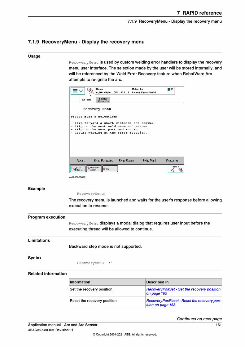
7.1.9 RecoveryMenu - Display the recovery menu
UsageRecoveryMenu is used by custom welding error handlers to display the recoverymenu user interface. The selection made by the user will be stored internally, andwill be referenced by the Weld Error Recovery feature when RobotWare Arcattempts to re-ignite the arc.
en1200000692
ExampleRecoveryMenu;
The recovery menu is launched and waits for the user's response before allowingexecution to resume.
Program executionRecoveryMenu displays a modal dialog that requires user input before theexecuting thread will be allowed to continue.
LimitationsBackward step mode is not supported.
SyntaxRecoveryMenu ';'
Related information
Described inInformation
RecoveryPosSet - Set the recovery positionon page 165
Set the recovery position
RecoveryPosReset - Reset the recovery pos-ition on page 168
Reset the recovery position
Continues on next pageApplication manual - Arc and Arc Sensor 1613HAC050988-001 Revision: H
© Copyright 2004-2021 ABB. All rights reserved.
7 RAPID reference7.1.9 RecoveryMenu - Display the recovery menu

Described inInformation
Configure the recovery menu on page 63Configure the recovery menu
ConfiguringWeld Error Recovery on page61Configuring Weld Error Recovery
162 Application manual - Arc and Arc Sensor3HAC050988-001 Revision: H
© Copyright 2004-2021 ABB. All rights reserved.
7 RAPID reference7.1.9 RecoveryMenu - Display the recovery menuContinued
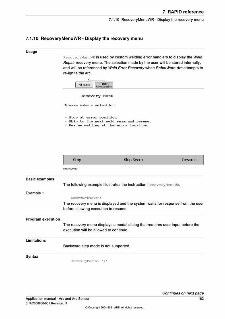
7.1.10 RecoveryMenuWR - Display the recovery menu
UsageRecoveryMenuWR is used by custom welding error handlers to display the WeldRepair recovery menu. The selection made by the user will be stored internally,and will be referenced by Weld Error Recovery when RobotWare Arc attempts tore-ignite the arc.
en1300000301
Basic examplesThe following example illustrates the instruction RecoveryMenuWR.
Example 1RecoveryMenuWR;
The recovery menu is displayed and the system waits for response from the userbefore allowing execution to resume.
Program executionThe recovery menu displays a modal dialog that requires user input before theexecution will be allowed to continue.
LimitationsBackward step mode is not supported.
SyntaxRecoveryMenuWR ';'
Continues on next pageApplication manual - Arc and Arc Sensor 1633HAC050988-001 Revision: H
© Copyright 2004-2021 ABB. All rights reserved.
7 RAPID reference7.1.10 RecoveryMenuWR - Display the recovery menu

Related information
SeeFor information about
RecoveryMenu - Display the recovery menu onpage 161
The instruction RecoveryMenu
164 Application manual - Arc and Arc Sensor3HAC050988-001 Revision: H
© Copyright 2004-2021 ABB. All rights reserved.
7 RAPID reference7.1.10 RecoveryMenuWR - Display the recovery menuContinued
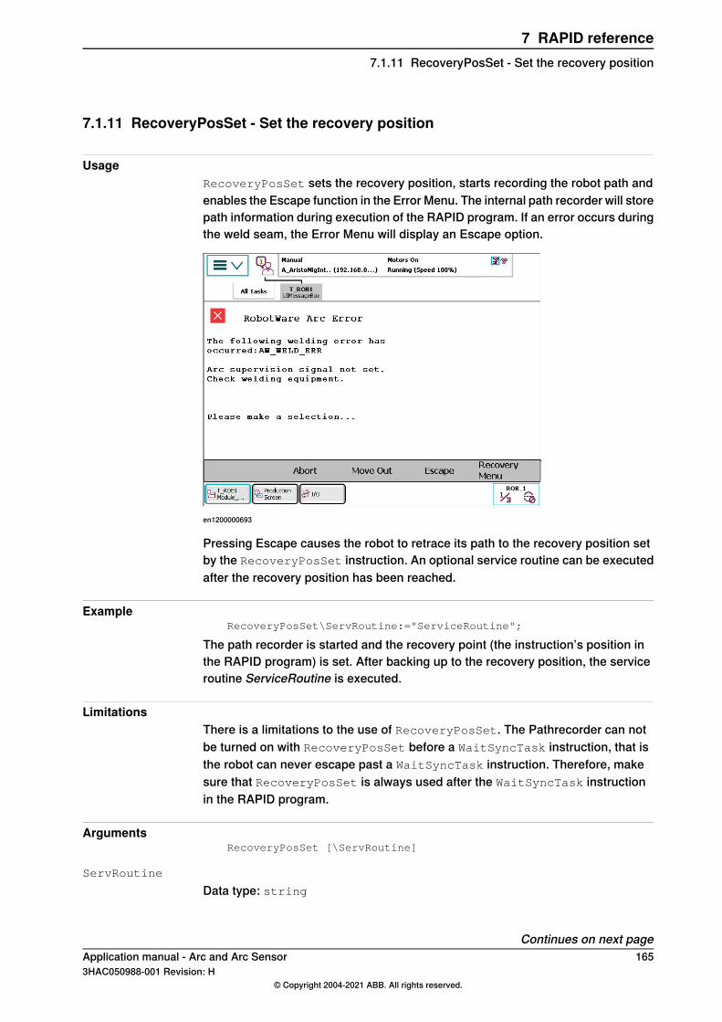
7.1.11 RecoveryPosSet - Set the recovery position
UsageRecoveryPosSet sets the recovery position, starts recording the robot path andenables the Escape function in the Error Menu. The internal path recorder will storepath information during execution of the RAPID program. If an error occurs duringthe weld seam, the Error Menu will display an Escape option.
en1200000693
Pressing Escape causes the robot to retrace its path to the recovery position setby the RecoveryPosSet instruction. An optional service routine can be executedafter the recovery position has been reached.
ExampleRecoveryPosSet\ServRoutine:="ServiceRoutine";
The path recorder is started and the recovery point (the instruction’s position inthe RAPID program) is set. After backing up to the recovery position, the serviceroutine ServiceRoutine is executed.
LimitationsThere is a limitations to the use of RecoveryPosSet. The Pathrecorder can notbe turned on with RecoveryPosSet before a WaitSyncTask instruction, that isthe robot can never escape past a WaitSyncTask instruction. Therefore, makesure that RecoveryPosSet is always used after the WaitSyncTask instructionin the RAPID program.
ArgumentsRecoveryPosSet [\ServRoutine]
ServRoutine
Data type: string
Continues on next pageApplication manual - Arc and Arc Sensor 1653HAC050988-001 Revision: H
© Copyright 2004-2021 ABB. All rights reserved.
7 RAPID reference7.1.11 RecoveryPosSet - Set the recovery position
Using the ServRoutine argument will extend the Weld Error Recovery escapefunctionality. The Service Routine is a user-defined procedure that is launchedafter the robot retraces a recorded path back to a recovery position. The routinemay be used to move the robot from the recovery position to a service location,or any other behavior that can be implemented in RAPID.
Program executionWhen the path recorder is ordered to start, the robot path will be recorded internallyin the robot controller. At welding error the recorded sequence of program positionscan be traversed backwards by selecting the Escape option from the Error Menu,causing the robot to move backwards along its executed path to the recoveryposition.Recovery positions may be set at any point in a weld sequence. In some cases itmay be necessary to have an alternate recovery position that is set mid-weld. Thisis perfectly ok.
ExamplePROC MyWeld()
MoveJ pSafe,vmax,z10,tWeldGun;
RecoveryPosSet\ServRoutine:="ServiceRoutine";
MoveJ *,vmax,z10,tWeldGun;
ArcLStart *,v500,sm1,wd1\Weave:=wv1,fine,tWeldGun;
ArcL *,v500,sm1,wd1\Weave:=wv1,z10,tWeldGun;
SetDO doClamp,high;
RecoveryPosSet;
ArcL *,v500,sm1,wd1\Weave:=wv1,z10,tWeldGun;
ArcLEnd *,v500,sm1,wd1\Weave:=wv1,fine,tWeldGun;
MoveJ *,vmax,z10,tWeldGun;
MoveJ *,vmax,z10,tWeldGun;
RecoveryPosReset;
ENDPROC
PROC ServiceRoutine()
MoveJ *,vmax,z10,tool0;
MoveL pService,vmax,z10,tool0;
RecoveryMenu;
MoveL *,vmax,z10,tool0;
ENDPROC
SyntaxRecoveryPosSet
['\' ServRoutine ':=' <expression (IN) of string>]';'
Related information
Described inInformation
RecoveryPosReset - Reset the recovery pos-ition on page 168
Reset the recovery position
RecoveryMenu - Display the recovery menuon page 161
Display the recovery menu
Continues on next page166 Application manual - Arc and Arc Sensor
3HAC050988-001 Revision: H© Copyright 2004-2021 ABB. All rights reserved.
7 RAPID reference7.1.11 RecoveryPosSet - Set the recovery positionContinued

Described inInformation
Configure the recovery menu on page 63Configure the recovery menu
ConfiguringWeld Error Recovery on page61Configure weld error recovery
Application manual - Arc and Arc Sensor 1673HAC050988-001 Revision: H
© Copyright 2004-2021 ABB. All rights reserved.
7 RAPID reference7.1.11 RecoveryPosSet - Set the recovery position
Continued
7.1.12 RecoveryPosReset - Reset the recovery position
UsageRecoveryPosReset resets the recovery position, stops recording the robot pathand the service routine is cleared.
ExampleRecoveryPosReset;
The path recorder is stopped and the recovery position is reset. If a service routinewas active it is cleared.
Program executionThis instruction should be used at the end of the weld sequence to ensure that thepath recorder is stopped and cleared before starting a new weld sequence. A failureto do so could result in undesirable results, as an old recovery set point couldremain active during a new weld sequence.
ExamplePROC MyWeld()
MoveJ pSafe,vmax,z10,tWeldGun;
RecoveryPosSet\ServRoutine:="ServiceRoutine";
MoveJ *,vmax,z10,tWeldGun;
ArcLStart *,v500,sm1,wd1\Weave:=wv1,fine,tWeldGun;
ArcL *,v500,sm1,wd1\Weave:=wv1,z10,tWeldGun;
SetDO doClamp,high;
RecoveryPosSet;
ArcL *,v500,sm1,wd1\Weave:=wv1,z10,tWeldGun;
ArcLEnd *,v500,sm1,wd1\Weave:=wv1,fine,tWeldGun;
MoveJ *,vmax,z10,tWeldGun;
MoveJ *,vmax,z10,tWeldGun;
RecoveryPosReset;
ENDPROC
PROC ServiceRoutine()
MoveJ *,vmax,z10,tool0;
MoveL pService,vmax,z10,tool0;
RecoveryMenu;
MoveL *,vmax,z10,tool0;
ENDPROC
SyntaxRecoveryPosReset ';'
Related information
Described inInformation
RecoveryPosSet - Set the recovery positionon page 165
Set the recovery position
RecoveryMenu - Display the recovery menuon page 161
Display the recovery menu
Continues on next page168 Application manual - Arc and Arc Sensor
3HAC050988-001 Revision: H© Copyright 2004-2021 ABB. All rights reserved.
7 RAPID reference7.1.12 RecoveryPosReset - Reset the recovery position

Described inInformation
Configure the recovery menu on page 63Configure the recovery menu
ConfiguringWeld Error Recovery on page61Configure weld error recovery
Application manual - Arc and Arc Sensor 1693HAC050988-001 Revision: H
© Copyright 2004-2021 ABB. All rights reserved.
7 RAPID reference7.1.12 RecoveryPosReset - Reset the recovery position
Continued
7.1.13 SetWRProcName - Set name of process to re-execute
UsageSetWRProcName is used to informRobotWare Arcwhich welding procedure needsto be re-executed by the weld repair function. The optional switch\Flexpositioner should be used in a FlexPositioner setup in the non-weldingrobot to inform WeldRepair that the task is not welding.
Basic examplesThe following example illustrates the instruction SetWRProcName.
Example 1SetWRProcName "Weldseam_1";
The RAPID procedure Weldseam_1 is re-executed if the weld repair function isactive.
ArgumentsSetWRProcName st1 [\FlexPositioner]
st1
Data type: stringThe name of the welding procedure that should be re-executed.
[\FlexPositioner]
Data type: switchThe robot/task is considered to be a non-welding robot if this argument is present.Should be used in a FlexPositioner setup.
SyntaxSetWRProcName
[st1 <expression (IN) of string>]
['\' FlexPositioner ] ';'
170 Application manual - Arc and Arc Sensor3HAC050988-001 Revision: H
© Copyright 2004-2021 ABB. All rights reserved.
7 RAPID reference7.1.13 SetWRProcName - Set name of process to re-execute
7.2 Data types
7.2.1 advSeamData - Advanced seam data
UsageadvSeamData is used to configure the restart behavior Seam local. Normally therestart behavior such as number of retries, restart distance, skip forward distance,and scrape start behavior is defined globally in the system parameters (PROC.cfg).These settings are used on all welds in the system. With advSeamData the behaviorcan be defined for each seam.
Note
AdvSeamData can only be used if the system is configured in Semi AutomaticMode 2.
Basic examplesThe following example illustrates the data type advSeamData.
Example 1PROC Weld_1()
SetWRProcName "Weld_1";
SyncMoveOn sync001, allTasks;
MoveL p10\ID:=10, vmax, z10, tWeldGun;
RecoveryPosSet\ServRoutine:="mvToService";
ArcLStart p20\ID:=20, v100, sm1\AdvData:=adv1, wd1, fine,tWeldGun;
ArcL p30\ID:=30, v100, sm1, wd1, z10, tWeldGun;
ArcLEnd p40\ID:=40, v100, sm1, wd1, fine, tWeldGun;
RecoveryPosReset;
MoveJ p50\ID:=50, vmax, z10, tWeldGun;
SyncMoveOff sync_testblech_2;
ENDPROC
Component group: ErrorFunc
RetractWire
Data type: boolSpecifies if the welding wire should be retracted after the configured number ofretries is exceeded.Default value: FALSE
RetractTime
Data type: numTime in seconds for wire retract.
Continues on next pageApplication manual - Arc and Arc Sensor 1713HAC050988-001 Revision: H
© Copyright 2004-2021 ABB. All rights reserved.
7 RAPID reference7.2.1 advSeamData - Advanced seam data
Default value: FALSEThe maximum allowed value is 2.25
NuOfRetries
Data type: numThe number of automatic restart attempts per seam at welding interrupts.Default value: 0
NuOfWeldErrors
Data type: numNumbers of allowed weld errors per seam.Default value: 0
SkipForwardDist
Data type: numThe distance in mm that the robot moves forward on the current seam relative tothe position where it was interrupted.Default value: 0The maximum allowed value is 50
RestartDist
Data type: numThe distance that the robot reverses on the current seam relative to the positionwhere it was interrupted.Default value: 0
Component group: ScrapeFunc
ScrapeStart
Data type: boolSpecifies if the robot is to weave at the actual weld start (scrape start). This weavingis automatically interrupted when the arc is ignited.Default value: FALSE
ScrapeDir
Data type: numThe angle of direction of the weave for a scrape start. It is specified in degrees,where 0 implies a weave that is carried out at a 90 degrees angle to the directionof the weld.Default value: 0
ScrapeTime
Data type: numThe time (in seconds) it takes for a complete weave cycle for a scrape start.Default value: 0.2
Continues on next page172 Application manual - Arc and Arc Sensor
3HAC050988-001 Revision: H© Copyright 2004-2021 ABB. All rights reserved.
7 RAPID reference7.2.1 advSeamData - Advanced seam dataContinued
ScrapeWidth
Data type: numThe width of the weave pattern for a scrape start.Default value: 0
LimitationsAdvSeamData can only be used if the system is configured in Semi AutomaticMode.
Application manual - Arc and Arc Sensor 1733HAC050988-001 Revision: H
© Copyright 2004-2021 ABB. All rights reserved.
7 RAPID reference7.2.1 advSeamData - Advanced seam data
Continued
7.2.2 arcdata - Arc data
Usage and descriptionarcdata is a data structure which is a subdata component of seamdata andwelddata. It contains components that are commonly used in both data types.
Components
sched (schedule)Data type: numThe identity (expressed as a number) of weld programs to send to the weldingequipment. This parameter is only available if schedule port type (see Systemparameters on page 201) is defined as 1 (Binary), or 2 (Pulse), or 3 (CAN).
mode
Data type: numThe identity (expressed as a number) of weld mode to send to the weldingequipment.This parameter is only available if schedule port type (see System parameters onpage 201) is defined as 2 (Pulse) or 3 (CAN).
voltage
Data type: numThe welding voltage (in Volt) during the weld phase.The value specified is scaled and sent to the corresponding analog output, inaccordance with the setting in Defining arc welding systems on page 202. Thisparameter is only available if weld voltage (System parameters on page 201) isdefined.
wirefeed
Data type: numThis parameter is only available, if wirefeed (System parameters on page 201) isdefined. The feed speed of the weld electrode during the weld phase. The unit forarcdata components that specify a velocity, is defined by the parameter Units,see The type Arc Robot Properties on page 208.The value specified is scaled and sent to the corresponding analog output, inaccordance with the setting in Defining arc welding systems on page 202.
control
Data type: numAnalog tuning value sent to certain welders.
current
Data type: numThe welding current (in Ampere) during the weld phase.
Continues on next page174 Application manual - Arc and Arc Sensor
3HAC050988-001 Revision: H© Copyright 2004-2021 ABB. All rights reserved.
7 RAPID reference7.2.2 arcdata - Arc data
The value specified is scaled and sent to the corresponding analog output, inaccordance with the setting in Defining arc welding systems on page 202. Thisparameter is only available if current (System parameters on page 201) is defined.
voltage2
Data type: numThe welding voltage (in Volt) during the weld phase. Used in a TwinWire setup.The value specified is scaled and sent to the corresponding analog output, inaccordance with the setting in Defining arc welding systems on page 202. Thisparameter is only available if weld voltage (System parameters on page 201) isdefined.
control2
Data type: numAnalog tuning value sent to certain welders. Used in a TwinWire setup.
Structure<data object of arcdata>
<sched of num>
<mode of num>
<voltage of num>
<wirefeed of num>
<control of num>
<current of num>
<voltage2 of num>
<wirefeed2 of num>
<control2 of num>
Related information
Described inInformation
seamdata - Seam data on page 177Seam data
System parameters on page 201Installation parameters for welding
Programming on page 21Process phases and time diagrams
ArcC, ArcC1, ArcC2 - Arc welding with circu-lar motion on page 107
Circular arc welding instructions
ArcL, ArcL1, ArcL2 - Arc welding with linearmotion on page 132
Linear arc welding instructions
Application manual - Arc and Arc Sensor 1753HAC050988-001 Revision: H
© Copyright 2004-2021 ABB. All rights reserved.
7 RAPID reference7.2.2 arcdata - Arc data
Continued
7.2.3 flystartdata - Flying start data
Usage and descriptionflystartdata is used to setup the needed parameters for a weld with a flyingstart.
Components
active
Data type: boolWhen active is TRUE, the ignition of the weld is done with a moving TCP (flyingstart).When active is FALSE, the ignition is done with a non moving TCP and the zoneis executed as a fine point. This makes it easy to test flying start without having tochange the zone parameter.Flying start cannot be used it in combination with Ignition Movement Delay or aScrape Start
superv_distance
Data type: numsuperv_distance sets the distance from the zone center to where an ignitionmust occur. If no ignition has occurred when the robot reaches this distance, thesystem stops and enter its error handler. The required action is then based on thesetup of the error handler.
Structure<data object of flystartdata>
<active of bool>
<superv_distance of num>
Related information
Described inInformation
ArcCStart, ArcC1Start, ArcC2Start - Arcwelding start with circular motion on page123
Arc welding start with circular motion
ArcLStart, ArcL1Start, ArcL2Start - Arc weld-ing start with linear motion on page 148
Arc welding start with linear motion
176 Application manual - Arc and Arc Sensor3HAC050988-001 Revision: H
© Copyright 2004-2021 ABB. All rights reserved.
7 RAPID reference7.2.3 flystartdata - Flying start data
7.2.4 seamdata - Seam data
Usage and descriptionseamdata is used to control the start and end of the weld. seamdata is also usedif the process is restarted after a welding operation has been interrupted.The actual weld phase is controlled using welddata, see welddata - Weld data onpage 196.seamdata describes data, which, as a rule, can be maintained unaltered during awhole seam and often also during welding several seams. seamdata is used duringthe start phase of a welding operation (ignition, heating after ignition) and duringthe final phase of the weld. seamdata is included in all arc welding instructions tofacilitate controlled start and end phases independent of where interrupts or restartsmight occur.All voltages can be expressed in two ways (determined by the welding equipment):
• As absolute values (only positive values are used in this case).• As corrections of values set in the process equipment (both positive and
negative values can be used in this case).Feeding the weld electrode in this section refers to MIG/MAG welding. For TIGwelding the following applies:
• A cold wire is supplied to the wire feed.• The necessary welding current reference value can be connected to any of
the three analog outputs that are not used. The Welding voltage referenceis not used.
Continues on next pageApplication manual - Arc and Arc Sensor 1773HAC050988-001 Revision: H
© Copyright 2004-2021 ABB. All rights reserved.
7 RAPID reference7.2.4 seamdata - Seam data
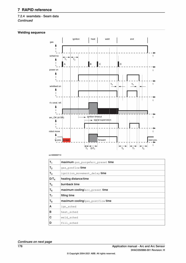
Welding sequence
gas
sched-no
power on
wirefeed on
4 x anal. ref.
arc_OK (di SR)
robot move
ignition weldheat end
ignition timeoutsignal supervision
forward next pos.to pos.
t
t
t
t
t
t
t
T1 T2
T5
T3 D/T4
scrape
T5
T6 T7 T8
DCBA
xx1200000713
maximum gas_purge/arc_preset timeT1
gas_preflow timeT2
ignition_movement_delay timeT3
heating distance/timeD/T4
burnback timeT5
maximum cooling/arc_preset timeT6
filling timeT7
maximum cooling/gas_postflow timeT8
ign_schedA
heat_schedB
weld_schedC
fill_schedD
Continues on next page178 Application manual - Arc and Arc Sensor
3HAC050988-001 Revision: H© Copyright 2004-2021 ABB. All rights reserved.
7 RAPID reference7.2.4 seamdata - Seam dataContinued
Component group: Ignition
purge_time
Data type: numThe time (in seconds) it takes to fill gas lines and the welding gun with protectivegas, so called "gas purging". The first weld instruction is an ArcLStart orArcLCStart, the gas flow is activated at the specified gas purge time before theprogrammed position is reached.If the positioning time to the start position of the weld is shorter than the gas purgetime, or if the ArcLStart or ArcCStart instruction is not used, the robot waits inthe weld start position until the gas purge time has expired.
preflow_time
Data type: numThe time (in seconds) it takes to preflow the weld object with protective gas, socalled "gas preflowing".The robot is stationary in position during this time before the arc is ignited.If a schedule based welder is used, the ignition schedule is sent to the welder atthe same time as the arc is ignited. This is in most cases too late for the welder.Setting the preflow_time to for example 0.2 seconds, will give the welder sometime to react on the schedule sent to it.
ign_arc
Data type: arcdataWeld parameters during the ignition phase. See definition of arcdata, arcdata -Arc data on page 174.
ign_move_delay (ignition movement delay)Data type: numThe delay (in seconds) from the time the arc is considered stable at ignition untilthe heating phase is started. The ignition references remain valid during the ignitionmovement delay.
scrape_start (scrape start type)Data type: numType of scrape at weld start. Scrape type at restart will not be affected. It will alwaysbe weaving scrape.Scrape types:
• 0 - No scrape. No scrape will occur at weld start.• 1 - Weaving scrape.
Component group: Heat
heat_speed
Data type: numThe welding speed during heating at the start of the weld phase.
Continues on next pageApplication manual - Arc and Arc Sensor 1793HAC050988-001 Revision: H
© Copyright 2004-2021 ABB. All rights reserved.
7 RAPID reference7.2.4 seamdata - Seam data
Continued
The unit for seamdata components that specify a velocity, is defined by parameterUnits, see The type Arc Robot Properties on page 208.
heat_time
Data type: numThe heating time (in seconds) at the start of the weld phase.Heat_time is only used during timed positioning and when heat_distance orheat_speed equal zero.
heat_distance
Data type: numThe distance along which heat data must be active at the start of the weld.The unit for seamdata components that specify a distance, is defined by parameterUnits, see The type Arc Robot Properties on page 208.
heat_arc
Data type: arcdataWeld parameters during the heat phase. See definition of arcdata - Arc data onpage 174.
Component group: End
cool_time (cooling time)Data type: numThe time (in seconds) during which the process is closed before other terminatingactivities (filling) take place.
fill_time
Data type: numThe crater-filling time (in seconds) at the end phase of the weld.This component needs ‘crater fill’ to be set for the Arc Welding function.
fill_arc
Data type: arcdataWeld parameters during the filling phase. See definition of arcdata, arcdata - Arcdata on page 174.
bback_time (burnback time)Data type: numThe time (in seconds) during which the weld electrode is burnt back when electrodefeeding has stopped. This to prevent the electrode getting stuck to the hardeningweld when a MIG/ MAG process is switched off. Burnback time is used twice inthe end phase; first when the weld phase is being finished, the second time aftercrater-filling. This component needs ‘burnback’ to be set for the Arc Weldingfunction.
rback_time (rollback time)Data type: num
Continues on next page180 Application manual - Arc and Arc Sensor
3HAC050988-001 Revision: H© Copyright 2004-2021 ABB. All rights reserved.
7 RAPID reference7.2.4 seamdata - Seam dataContinued
The time (in seconds) during which a cold wire is rolled back after the power sourcehas been switched off. This to prevent the wire getting stuck to the hardening weldwhen a TIG process is switched off. This component group ‘rollback’ to be set forthe Arc Welding function.
bback_arc
Data type: arcdataWeld parameters during the burnback and rollback phase. See definition ofarcdata, arcdata - Arc data on page 174.
postflow_time
Data type: numThe time (in seconds) required for purging with protective gas after the end of aprocess. The purpose of gas postflow is to prevent the weld electrode and theseam from oxidizing during cooling.
LimitationThere is no component for rollback wire feed in seamdata.However, the functionality can be achieved by using the wire feed component inthe burnback part of seamdata (bback_arc).To activate rollback functionality with rollback wire feed, the following needs to befulfilled:
• Rollback On needs to be activated in the topic Process (configuration).• Rollback Wirefeed On needs to be activated in the topic Process
(configuration).• Burnback On needs to be activated in the topic Process (configuration).• Burnback Voltage On needs to be activated in the topic Process
(configuration).If this is done, rollback time (rback_time) in seamdata and wirefeed componentin bback_arc will be visible.
Structure<data object of seamdata>
<purge_time of num>
<preflow_time of num>
<ign_arc of arcdata>
<ign_move_delay of num>
<scrape_start of num>
<heat_speed of num>
<heat_time of num>
<heat_distance of num>
<heat_arc of arcdata>
<cool_time of num>
<fill_time of num>
<fill_arc of arcdata>
<bback_time of num>
<rback_time of num>
Continues on next pageApplication manual - Arc and Arc Sensor 1813HAC050988-001 Revision: H
© Copyright 2004-2021 ABB. All rights reserved.
7 RAPID reference7.2.4 seamdata - Seam data
Continued
<bback_arc of arcdata>
<postflow_time of num>
Related information
Described inInformation
welddata - Weld data on page 196Weld data
arcdata - Arc data on page 174Arc data
System parameters on page 201Installation parameters for welding
Programming on page 21Process phases and time diagrams
ArcC, ArcC1, ArcC2 - Arc welding with circu-lar motion on page 107
Circular arc welding instruction
ArcL, ArcL1, ArcL2 - Arc welding with linearmotion on page 132
Linear arc welding instruction
182 Application manual - Arc and Arc Sensor3HAC050988-001 Revision: H
© Copyright 2004-2021 ABB. All rights reserved.
7 RAPID reference7.2.4 seamdata - Seam dataContinued
7.2.5 trackdata - Seam tracking data
Usage and descriptiontrackdata is used to control path corrections during the weld phase.trackdata used in a given instruction along a path affects the path correctionuntil the specified position is reached. Using instructions with different track data,it is thus possible to achieve optimum position control along an entire seam. Theoptional trackdata argument must be used during the whole weldseam, that is,from the ArcXStart to the ArcXEnd instruction.The process path should be programmed accurately with respect to the nominalgeometry and orientation of the work piece. The tracking function activated by theoptional trackdata argument will compensate for deviations from the nominalpath.The function best suited for welding applications with long strait seams with speedslower than 20 mm/s and orientation errors less than 10 deg.
Note
Some of the components of trackdata depend on the configuration of the robot.trackdata will only include component appropriate for the selected sensortype.
Components
track_system
Data type: numThis parameter defines which tracking system that is used, Optical or WeldGuide.It is also used for data masking of the trackdata. The track_device is configuredin the equipment configuration parameters.
store_path
Data type: boolParameter used when the path should be stored.
max_corr
Data type: numFor Optical:
• If the TCP offset due to path corrections is more than max_corr and Max
Correction Warning was set in the Optical Sensor Properties, therobot will continue its path but the applied path correction will not exceedmax_corr. If Max Correction Warning was not set, a track error isreported and program execution is stopped.
For WeldGuide:• The max_corr component defines the maximum path correction allowed. If
the TCP is offset more than max_corr by path corrections a track error isreported and program execution is stopped.
Continues on next pageApplication manual - Arc and Arc Sensor 1833HAC050988-001 Revision: H
© Copyright 2004-2021 ABB. All rights reserved.
7 RAPID reference7.2.5 trackdata - Seam tracking data
arctrack
Data type: arctrackdataTrack data with parameters for non-optical trackers (AWC).
opttrack
Data type: opttrackdataTrack data with parameters for optical trackers (laser trackers).
Structure of trackdata<data object of trackdata>
<track_system of num>
<store_path of bool>
<max_corr of num>
<arctrack of arctrackdata>
<opttrack of opttrackdata>
Components of arctrackdata
track_type
Data type: numThe parameter defines what type of tracking to be performed. The tracking typesavailable are: Center line, Adaptive, Right side, Left side and Height only. In orderfor the robot to track, the optional argument \Track must be added to each weldinstruction in the program.
DescriptionValue
Center line tracking0
Adaptive tracking1
Single side tracking (Right)2
Single side tracking (Left)3
Height only tracking (Constant stick-out length is kept) (a value of 4is reserved for TIG welding only)
4
Height only tracking (Constant stick-out length is kept)5
gain_y
Data type: numThe gain_y parameters define how big of a correction is sent to the robot. Thehigher the number the faster the system corrects. The range of this parameter isfrom 1 to 100. Initial starting values for this parameter depend on weave size. Startwith 30 for most weave widths and 5 for very small weave widths.
gain_z
Data type: numThe gain_z parameters define how big of a correction is sent to the robot. Thehigher the number the faster the system corrects. The range of this parameter isfrom 1 to 100. Initial starting values for this parameter depend on weave size. Startwith 30 for most weave widths and 5 for very small weave widths.
Continues on next page184 Application manual - Arc and Arc Sensor
3HAC050988-001 Revision: H© Copyright 2004-2021 ABB. All rights reserved.
7 RAPID reference7.2.5 trackdata - Seam tracking dataContinued
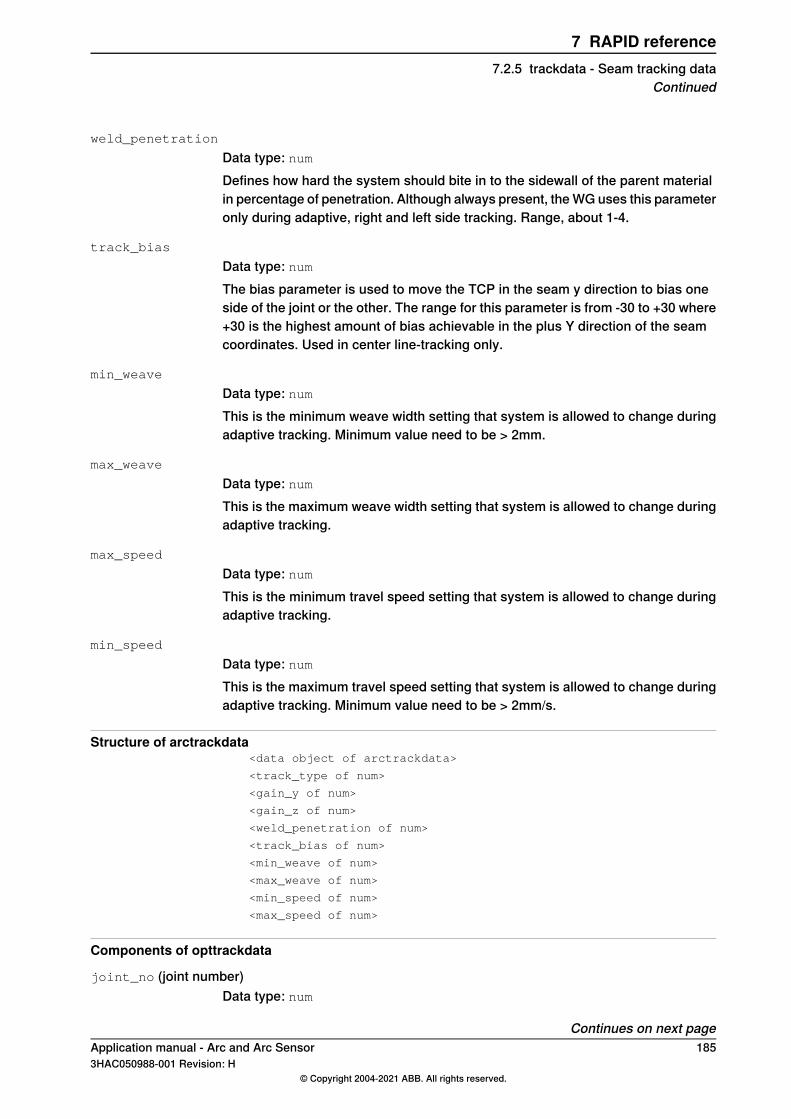
weld_penetration
Data type: numDefines how hard the system should bite in to the sidewall of the parent materialin percentage of penetration. Although always present, the WG uses this parameteronly during adaptive, right and left side tracking. Range, about 1-4.
track_bias
Data type: numThe bias parameter is used to move the TCP in the seam y direction to bias oneside of the joint or the other. The range for this parameter is from -30 to +30 where+30 is the highest amount of bias achievable in the plus Y direction of the seamcoordinates. Used in center line-tracking only.
min_weave
Data type: numThis is the minimum weave width setting that system is allowed to change duringadaptive tracking. Minimum value need to be > 2mm.
max_weave
Data type: numThis is the maximum weave width setting that system is allowed to change duringadaptive tracking.
max_speed
Data type: numThis is the minimum travel speed setting that system is allowed to change duringadaptive tracking.
min_speed
Data type: numThis is the maximum travel speed setting that system is allowed to change duringadaptive tracking. Minimum value need to be > 2mm/s.
Structure of arctrackdata<data object of arctrackdata>
<track_type of num>
<gain_y of num>
<gain_z of num>
<weld_penetration of num>
<track_bias of num>
<min_weave of num>
<max_weave of num>
<min_speed of num>
<max_speed of num>
Components of opttrackdata
joint_no (joint number)Data type: num
Continues on next pageApplication manual - Arc and Arc Sensor 1853HAC050988-001 Revision: H
© Copyright 2004-2021 ABB. All rights reserved.
7 RAPID reference7.2.5 trackdata - Seam tracking data
Continued
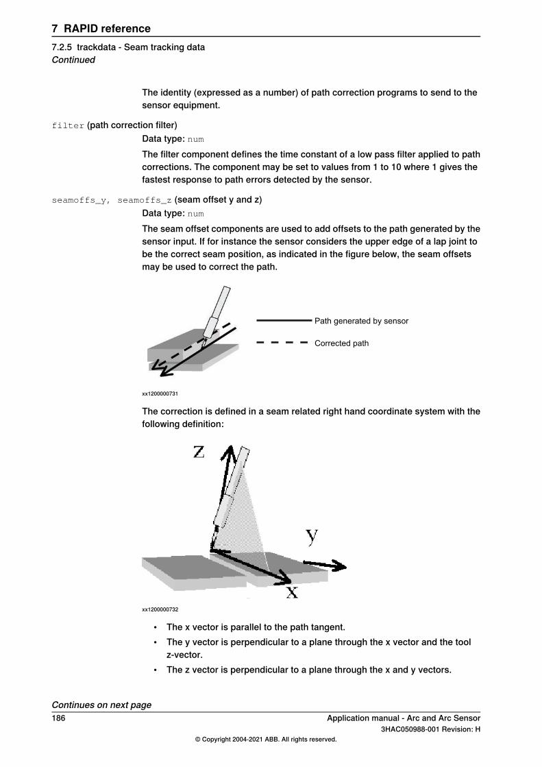
The identity (expressed as a number) of path correction programs to send to thesensor equipment.
filter (path correction filter)Data type: numThe filter component defines the time constant of a low pass filter applied to pathcorrections. The component may be set to values from 1 to 10 where 1 gives thefastest response to path errors detected by the sensor.
seamoffs_y, seamoffs_z (seam offset y and z)Data type: numThe seam offset components are used to add offsets to the path generated by thesensor input. If for instance the sensor considers the upper edge of a lap joint tobe the correct seam position, as indicated in the figure below, the seam offsetsmay be used to correct the path.
Path generated by sensor
Corrected path
xx1200000731
The correction is defined in a seam related right hand coordinate system with thefollowing definition:
xx1200000732
• The x vector is parallel to the path tangent.• The y vector is perpendicular to a plane through the x vector and the tool
z-vector.• The z vector is perpendicular to a plane through the x and y vectors.
Continues on next page186 Application manual - Arc and Arc Sensor
3HAC050988-001 Revision: H© Copyright 2004-2021 ABB. All rights reserved.
7 RAPID reference7.2.5 trackdata - Seam tracking dataContinued
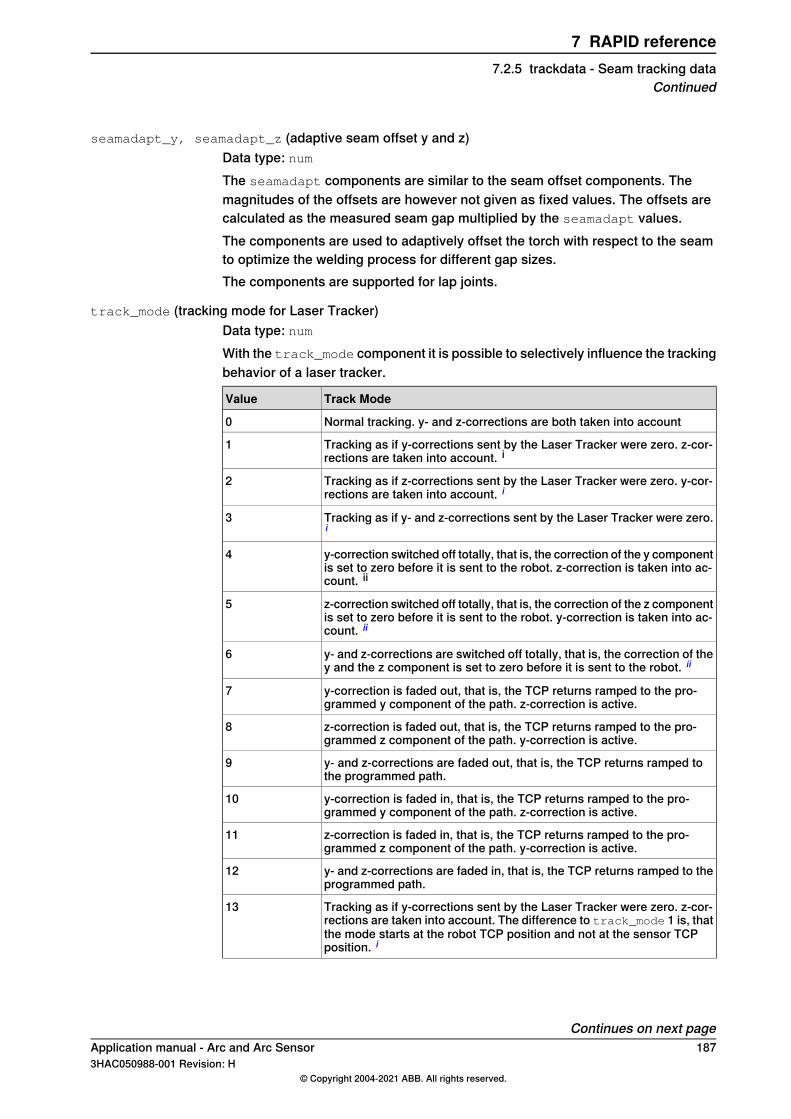
seamadapt_y, seamadapt_z (adaptive seam offset y and z)Data type: numThe seamadapt components are similar to the seam offset components. Themagnitudes of the offsets are however not given as fixed values. The offsets arecalculated as the measured seam gap multiplied by the seamadapt values.The components are used to adaptively offset the torch with respect to the seamto optimize the welding process for different gap sizes.The components are supported for lap joints.
track_mode (tracking mode for Laser Tracker)Data type: numWith the track_mode component it is possible to selectively influence the trackingbehavior of a laser tracker.
Track ModeValue
Normal tracking. y- and z-corrections are both taken into account0
Tracking as if y-corrections sent by the Laser Tracker were zero. z-cor-rections are taken into account. i
1
Tracking as if z-corrections sent by the Laser Tracker were zero. y-cor-rections are taken into account. i
2
Tracking as if y- and z-corrections sent by the Laser Tracker were zero.i
3
y-correction switched off totally, that is, the correction of the y componentis set to zero before it is sent to the robot. z-correction is taken into ac-count. ii
4
z-correction switched off totally, that is, the correction of the z componentis set to zero before it is sent to the robot. y-correction is taken into ac-count. ii
5
y- and z-corrections are switched off totally, that is, the correction of they and the z component is set to zero before it is sent to the robot. ii
6
y-correction is faded out, that is, the TCP returns ramped to the pro-grammed y component of the path. z-correction is active.
7
z-correction is faded out, that is, the TCP returns ramped to the pro-grammed z component of the path. y-correction is active.
8
y- and z-corrections are faded out, that is, the TCP returns ramped tothe programmed path.
9
y-correction is faded in, that is, the TCP returns ramped to the pro-grammed y component of the path. z-correction is active.
10
z-correction is faded in, that is, the TCP returns ramped to the pro-grammed z component of the path. y-correction is active.
11
y- and z-corrections are faded in, that is, the TCP returns ramped to theprogrammed path.
12
Tracking as if y-corrections sent by the Laser Tracker were zero. z-cor-rections are taken into account. The difference to track_mode 1 is, thatthe mode starts at the robot TCP position and not at the sensor TCPposition. i
13
Continues on next pageApplication manual - Arc and Arc Sensor 1873HAC050988-001 Revision: H
© Copyright 2004-2021 ABB. All rights reserved.
7 RAPID reference7.2.5 trackdata - Seam tracking data
Continued
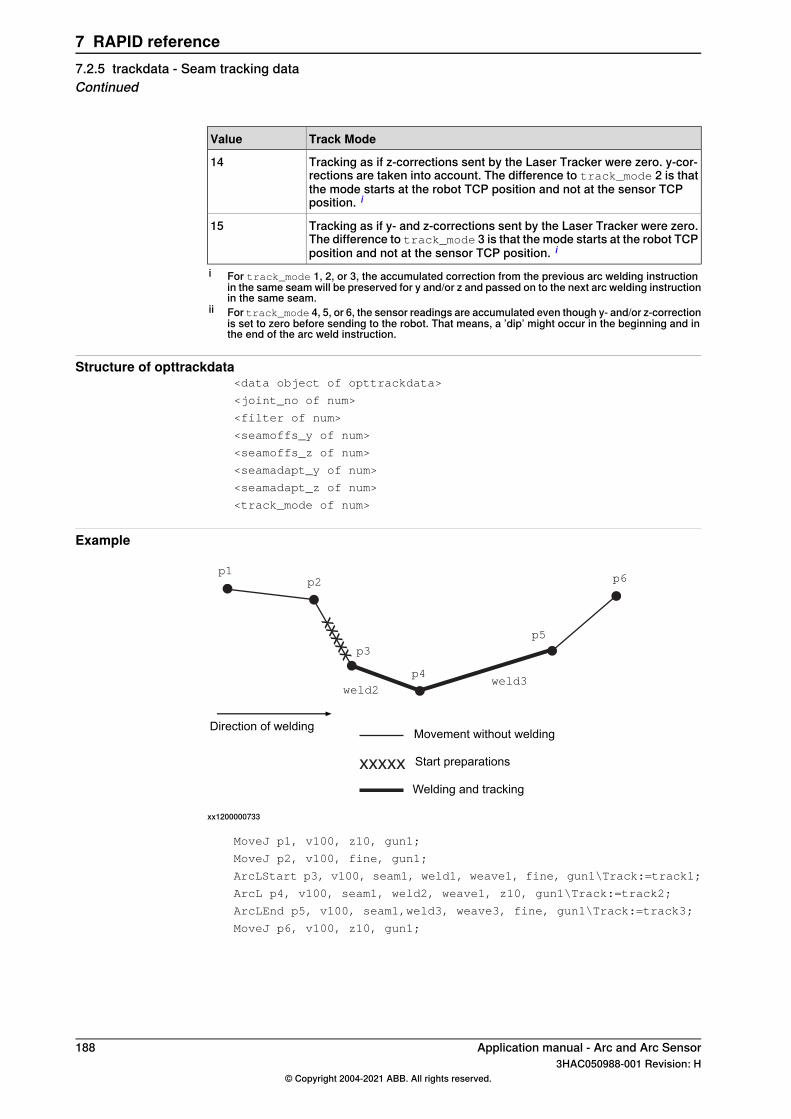
Track ModeValue
Tracking as if z-corrections sent by the Laser Tracker were zero. y-cor-rections are taken into account. The difference to track_mode 2 is thatthe mode starts at the robot TCP position and not at the sensor TCPposition. i
14
Tracking as if y- and z-corrections sent by the Laser Tracker were zero.The difference to track_mode 3 is that the mode starts at the robot TCPposition and not at the sensor TCP position. i
15
i For track_mode 1, 2, or 3, the accumulated correction from the previous arc welding instructionin the same seam will be preserved for y and/or z and passed on to the next arc welding instructionin the same seam.
ii For track_mode 4, 5, or 6, the sensor readings are accumulated even though y- and/or z-correctionis set to zero before sending to the robot. That means, a ’dip’ might occur in the beginning and inthe end of the arc weld instruction.
Structure of opttrackdata<data object of opttrackdata>
<joint_no of num>
<filter of num>
<seamoffs_y of num>
<seamoffs_z of num>
<seamadapt_y of num>
<seamadapt_z of num>
<track_mode of num>
Example
xxxxx
xxxxx
p1p2
p5
p6
weld2
Movement without welding
Welding and tracking
Start preparations
Direction of welding
weld3
p3
p4
xx1200000733
MoveJ p1, v100, z10, gun1;
MoveJ p2, v100, fine, gun1;
ArcLStart p3, v100, seam1, weld1, weave1, fine, gun1\Track:=track1;
ArcL p4, v100, seam1, weld2, weave1, z10, gun1\Track:=track2;
ArcLEnd p5, v100, seam1,weld3, weave3, fine, gun1\Track:=track3;
MoveJ p6, v100, z10, gun1;
188 Application manual - Arc and Arc Sensor3HAC050988-001 Revision: H
© Copyright 2004-2021 ABB. All rights reserved.
7 RAPID reference7.2.5 trackdata - Seam tracking dataContinued
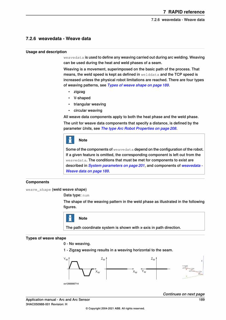
7.2.6 weavedata - Weave data
Usage and descriptionweavedata is used to define any weaving carried out during arc welding. Weavingcan be used during the heat and weld phases of a seam.Weaving is a movement, superimposed on the basic path of the process. Thatmeans, the weld speed is kept as defined in welddata and the TCP speed isincreased unless the physical robot limitations are reached. There are four typesof weaving patterns, see Types of weave shape on page 189.
• zigzag• V-shaped• triangular weaving• circular weaving
All weave data components apply to both the heat phase and the weld phase.The unit for weave data components that specify a distance, is defined by theparameter Units, see The type Arc Robot Properties on page 208.
Note
Some of the components of weavedata depend on the configuration of the robot.If a given feature is omitted, the corresponding component is left out from theweavedata. The conditions that must be met for components to exist aredescribed in System parameters on page 201, and components of weavedata -Weave data on page 189.
Components
weave_shape (weld weave shape)Data type: numThe shape of the weaving pattern in the weld phase as illustrated in the followingfigures.
Note
The path coordinate system is shown with x-axis in path direction.
Types of weave shape0 - No weaving.1 - Zigzag weaving results in a weaving horizontal to the seam.
YW
XW
ZW
XW
ZW
YW
xx1200000714
Continues on next pageApplication manual - Arc and Arc Sensor 1893HAC050988-001 Revision: H
© Copyright 2004-2021 ABB. All rights reserved.
7 RAPID reference7.2.6 weavedata - Weave data
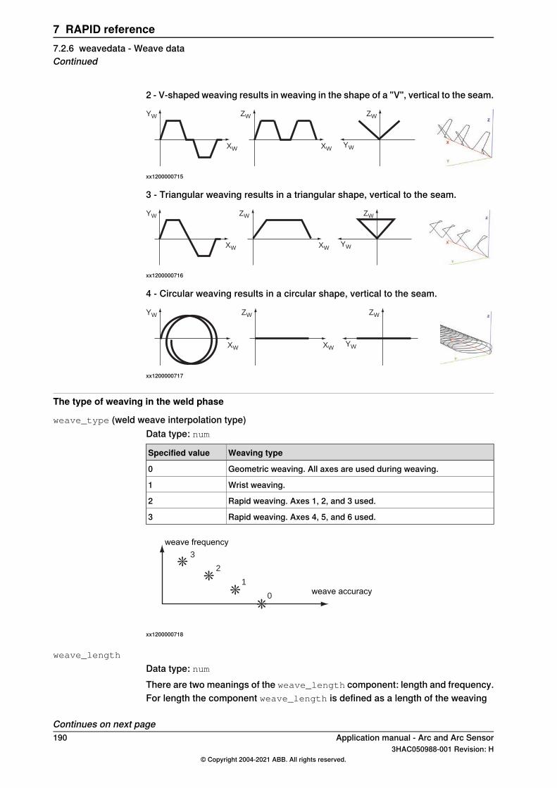
2 - V-shaped weaving results in weaving in the shape of a "V", vertical to the seam.
YW
XW
ZW
XW
ZW
YW
xx1200000715
3 - Triangular weaving results in a triangular shape, vertical to the seam.
YW
XW
ZW
XW
ZW
YW
xx1200000716
4 - Circular weaving results in a circular shape, vertical to the seam.
YW
XW
ZW
XW
ZW
YW
xx1200000717
The type of weaving in the weld phase
weave_type (weld weave interpolation type)Data type: num
Weaving typeSpecified value
Geometric weaving. All axes are used during weaving.0
Wrist weaving.1
Rapid weaving. Axes 1, 2, and 3 used.2
Rapid weaving. Axes 4, 5, and 6 used.3
****
3
2
1
0weave accuracy
weave frequency
xx1200000718
weave_length
Data type: numThere are two meanings of the weave_length component: length and frequency.For length the component weave_length is defined as a length of the weaving
Continues on next page190 Application manual - Arc and Arc Sensor
3HAC050988-001 Revision: H© Copyright 2004-2021 ABB. All rights reserved.
7 RAPID reference7.2.6 weavedata - Weave dataContinued
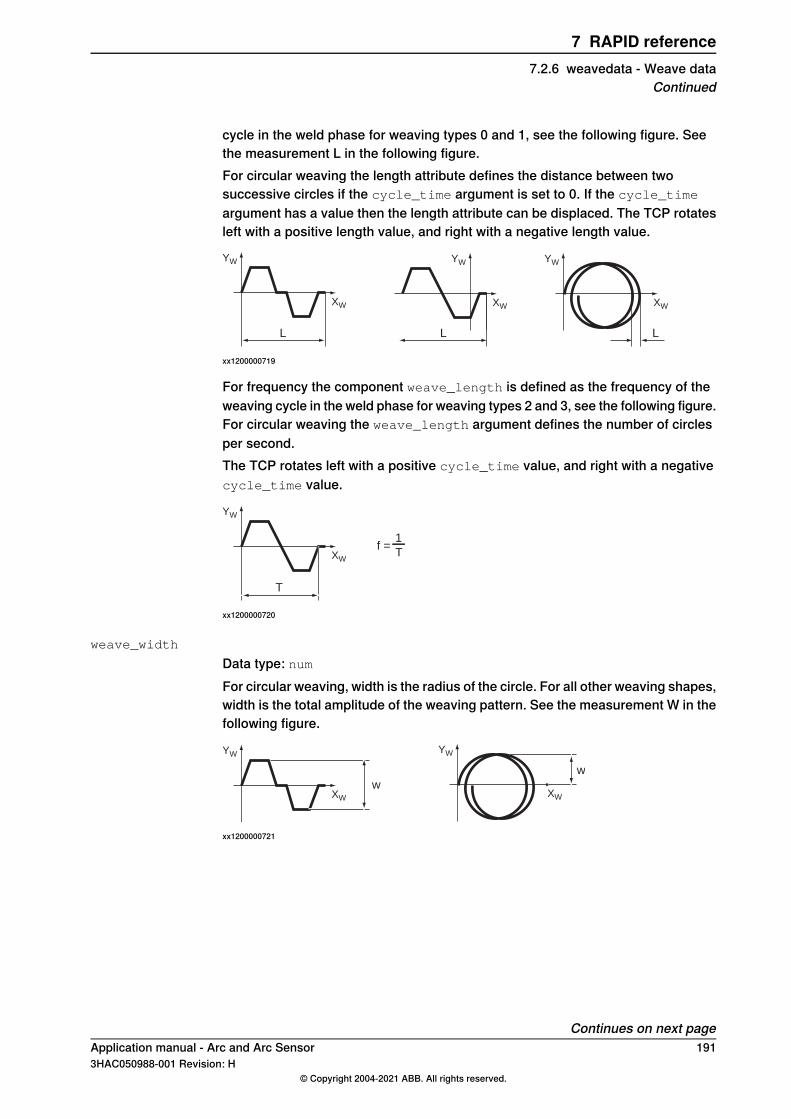
cycle in the weld phase for weaving types 0 and 1, see the following figure. Seethe measurement L in the following figure.For circular weaving the length attribute defines the distance between twosuccessive circles if the cycle_time argument is set to 0. If the cycle_time
argument has a value then the length attribute can be displaced. The TCP rotatesleft with a positive length value, and right with a negative length value.
YW
XW
YW
XW
YW
XW
L L L
xx1200000719
For frequency the component weave_length is defined as the frequency of theweaving cycle in the weld phase for weaving types 2 and 3, see the following figure.For circular weaving the weave_length argument defines the number of circlesper second.The TCP rotates left with a positive cycle_time value, and right with a negativecycle_time value.
YW
XW
T
f =1
T
xx1200000720
weave_width
Data type: numFor circular weaving, width is the radius of the circle. For all other weaving shapes,width is the total amplitude of the weaving pattern. See the measurement W in thefollowing figure.
YW
XW
YW
XW
w
w
xx1200000721
Continues on next pageApplication manual - Arc and Arc Sensor 1913HAC050988-001 Revision: H
© Copyright 2004-2021 ABB. All rights reserved.
7 RAPID reference7.2.6 weavedata - Weave data
Continued
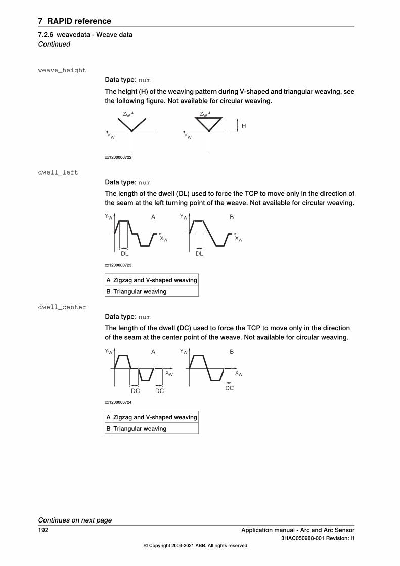
weave_height
Data type: numThe height (H) of the weaving pattern during V-shaped and triangular weaving, seethe following figure. Not available for circular weaving.
ZW
YW
ZW
YW
H
xx1200000722
dwell_left
Data type: numThe length of the dwell (DL) used to force the TCP to move only in the direction ofthe seam at the left turning point of the weave. Not available for circular weaving.
YW
XW
YW
XW
DL
A B
DL
xx1200000723
Zigzag and V-shaped weavingA
Triangular weavingB
dwell_center
Data type: numThe length of the dwell (DC) used to force the TCP to move only in the directionof the seam at the center point of the weave. Not available for circular weaving.
YW
XW
YW
XW
DC DC
A B
DC
xx1200000724
Zigzag and V-shaped weavingA
Triangular weavingB
Continues on next page192 Application manual - Arc and Arc Sensor
3HAC050988-001 Revision: H© Copyright 2004-2021 ABB. All rights reserved.
7 RAPID reference7.2.6 weavedata - Weave dataContinued
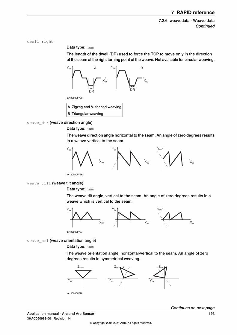
dwell_right
Data type: numThe length of the dwell (DR) used to force the TCP to move only in the directionof the seam at the right turning point of the weave. Not available for circular weaving.
YW
XW
YW
XW
DR
A B
DR
xx1200000725
Zigzag and V-shaped weavingA
Triangular weavingB
weave_dir (weave direction angle)Data type: numThe weave direction angle horizontal to the seam. An angle of zero degrees resultsin a weave vertical to the seam.
YW
XW
YW
XW
YW
XW
xx1200000726
weave_tilt (weave tilt angle)Data type: numThe weave tilt angle, vertical to the seam. An angle of zero degrees results in aweave which is vertical to the seam.
YW
XW
YW
XW
YW
XW
xx1200000727
weave_ori (weave orientation angle)Data type: numThe weave orientation angle, horizontal-vertical to the seam. An angle of zerodegrees results in symmetrical weaving.
ZW
YW
ZW
YW
ZW
YW
xx1200000728
Continues on next pageApplication manual - Arc and Arc Sensor 1933HAC050988-001 Revision: H
© Copyright 2004-2021 ABB. All rights reserved.
7 RAPID reference7.2.6 weavedata - Weave data
Continued
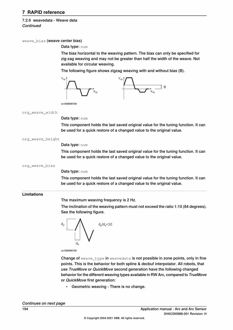
weave_bias (weave center bias)Data type: numThe bias horizontal to the weaving pattern. The bias can only be specified forzig-zag weaving and may not be greater than half the width of the weave. Notavailable for circular weaving.The following figure shows zigzag weaving with and without bias (B).
YW
XW
YW
XW
B
xx1200000729
org_weave_width
Data type: numThis component holds the last saved original value for the tuning function. It canbe used for a quick restore of a changed value to the original value.
org_weave_height
Data type: numThis component holds the last saved original value for the tuning function. It canbe used for a quick restore of a changed value to the original value.
org_weave_bias
Data type: numThis component holds the last saved original value for the tuning function. It canbe used for a quick restore of a changed value to the original value.
LimitationsThe maximum weaving frequency is 2 Hz.The inclination of the weaving pattern must not exceed the ratio 1:10 (84 degrees).See the following figure.
dy
dx
dy/dx<10
xx1200000730
Change of weave_type in weavedata is not possible in zone points, only in finepoints. This is the behavior for both spline & decbuf interpolator. All robots, thatuse TrueMove or QuickMove second generation have the following changedbehavior for the different weaving types available in RW Arc, compared to TrueMoveor QuickMove first generation:
• Geometric weaving - There is no change.
Continues on next page194 Application manual - Arc and Arc Sensor
3HAC050988-001 Revision: H© Copyright 2004-2021 ABB. All rights reserved.
7 RAPID reference7.2.6 weavedata - Weave dataContinued
• Wrist weaving - uses mainly the wrist axes (4, 5, and 6) but small correctionscan also be added to the main axes to be able to keep the pattern in thedesired plane.
• Rapid weaving - In TrueMove or QuickMove second generation bothgeometric weaving and wrist weaving have highly improved performance.Therefore Rapid weaving (both types) is not necessary as a special weavingtype any more.Rapid weaving axis 1, 2, and 3 is the same as geometric weaving.Rapid weaving axis 4, 5, and 6 is the same as wrist weaving.The weaving types are still available for backward compatibility.
The system uses TrueMove or QuickMove second generation, if there is a switchdyn_ipol_type 1 in MOC.cfg in the MOTION_PLANNER data (systemparameters).
Structure<data object of weavedata>
<weave_shape of num>
<weave_type of num>
<weave_length of num>
<weave_width of num>
<weave_height of num>
<dwell_left of num>
<dwell_center of num>
<dwell_right of num>
<weave_dir of num>
<weave_tilt of num>
<weave_ori of num>
<weave_bias of num>
<org_weave_width of num>
<org_weave_height of num>
<org_weave_bias of num>
Related information
Described inInformation
System parameters on page 201Installation parameters for welding equipmentand functions
Programming on page 21Process phases and timing schedules
ArcL, ArcL1, ArcL2 - Arc welding with linearmotion on page 132
Arc welding instructions
ArcC, ArcC1, ArcC2 - Arc welding with circu-lar motion on page 107
Application manual - Arc and Arc Sensor 1953HAC050988-001 Revision: H
© Copyright 2004-2021 ABB. All rights reserved.
7 RAPID reference7.2.6 weavedata - Weave data
Continued
7.2.7 welddata - Weld data
Usage and descriptionwelddata controls the weld during the weld phase, i.e. as long as the arc isestablished. Start, restart and end phases are controlled using seamdata - Seamdata on page 177.welddata describes data that normally vary along a seam. welddata used in agiven instruction along a path affects the weld until the specified position is reached.By using instructions with different weld data, it is thus possible to achieve optimumcontrol over the welding equipment along a seam. welddata affects the weld whenfusion has been established (after heating) at the start of a process.When using an ArcLStart or ArcCStart instruction, the arc is not ignited untilthe destination position is reached, which means that weld data does not have anyeffect on the weld in this instruction.When going from one arc welding instruction to another during a weld, the newweld data will be applied starting in the middle of the corner path.All voltages can be expressed in two ways (determined by the welding equipment):
• As absolute values (only positive values are used in this case).• As corrections of values set in the process equipment (both positive and
negative values are used in this case).Feeding the weld electrode in this section refers to MIG/MAG welding. For TIGwelding, a cold wire is supplied to the wire feed. The necessary welding currentreference value can be connected to any of the three analog outputs that are notused. The Welding voltage reference is not used.
ExampleMoveJ p1, v100, z10, gun1;
MoveJ p2, v100, fine, gun1;
ArcLStart p3, v100, seam1, weld1 \Weave:=weave1, fine, gun1;
ArcL p4, v100, seam1, weld2 \Weave:=weave1, z10, gun1;
ArcLEnd p5, v100, seam1,weld3 \Weave:=weave3, fine, gun1;
MoveJ p6, v100, z10, gun1;
Continues on next page196 Application manual - Arc and Arc Sensor
3HAC050988-001 Revision: H© Copyright 2004-2021 ABB. All rights reserved.
7 RAPID reference7.2.7 welddata - Weld data
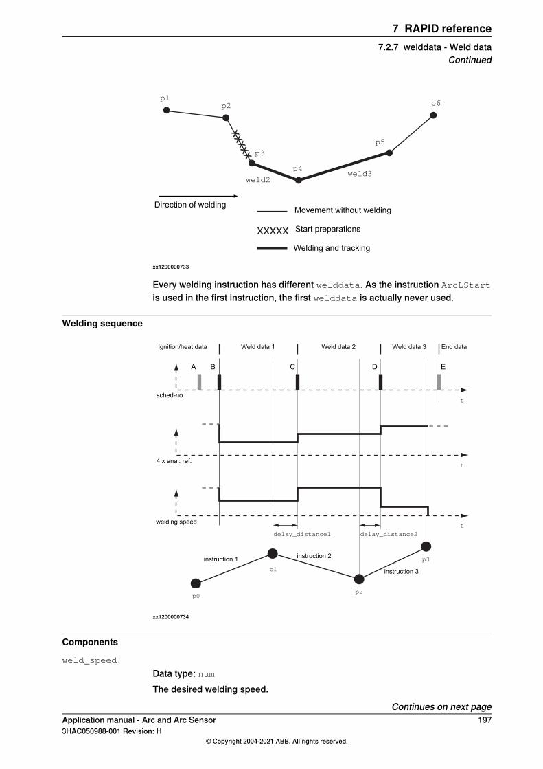
xxxxx
xxxxx
p1p2
p5
p6
weld2
Movement without welding
Welding and tracking
Start preparations
Direction of welding
weld3
p3
p4
xx1200000733
Every welding instruction has different welddata. As the instruction ArcLStart
is used in the first instruction, the first welddata is actually never used.
Welding sequence
Ignition/heat data Weld data 1 Weld data 2 Weld data 3 End data
sched-no
4 x anal. ref.
welding speed
delay_distance1 delay_distance2
p1
p0p2
p3instruction 1 instruction 2
instruction 3
t
t
t
A B C D E
xx1200000734
Components
weld_speed
Data type: numThe desired welding speed.
Continues on next pageApplication manual - Arc and Arc Sensor 1973HAC050988-001 Revision: H
© Copyright 2004-2021 ABB. All rights reserved.
7 RAPID reference7.2.7 welddata - Weld data
Continued
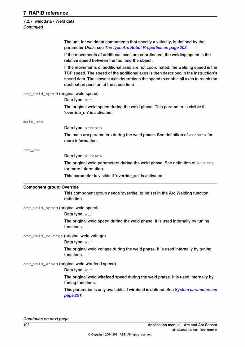
The unit for welddata components that specify a velocity, is defined by theparameter Units, see The type Arc Robot Properties on page 208.If the movements of additional axes are coordinated, the welding speed is therelative speed between the tool and the object.If the movements of additional axes are not coordinated, the welding speed is theTCP speed. The speed of the additional axes is then described in the instruction’sspeed data. The slowest axis determines the speed to enable all axes to reach thedestination position at the same time
org_weld_speed (original weld speed)Data type: numThe original weld speed during the weld phase. This parameter is visible if‘override_on’ is activated.
main_arc
Data type: arcdataThe main arc parameters during the weld phase. See definition of arcdata formore information.
org_arc
Data type: arcdataThe original weld parameters during the weld phase. See definition of arcdatafor more information.This parameter is visible if ‘override_on’ is activated.
Component group: OverrideThis component group needs ‘override’ to be set in the Arc Welding functiondefinition.
org_weld_speed (original weld speed)Data type: numThe original weld speed during the weld phase. It is used internally by tuningfunctions.
org_weld_voltage (original weld voltage)Data type: numThe original weld voltage during the weld phase. It is used internally by tuningfunctions.
org_weld_wfeed (original weld wirefeed speed)Data type: numThe original weld wirefeed speed during the weld phase. It is used internally bytuning functions.This parameter is only available, if wirefeed is defined. See System parameters onpage 201.
Continues on next page198 Application manual - Arc and Arc Sensor
3HAC050988-001 Revision: H© Copyright 2004-2021 ABB. All rights reserved.
7 RAPID reference7.2.7 welddata - Weld dataContinued
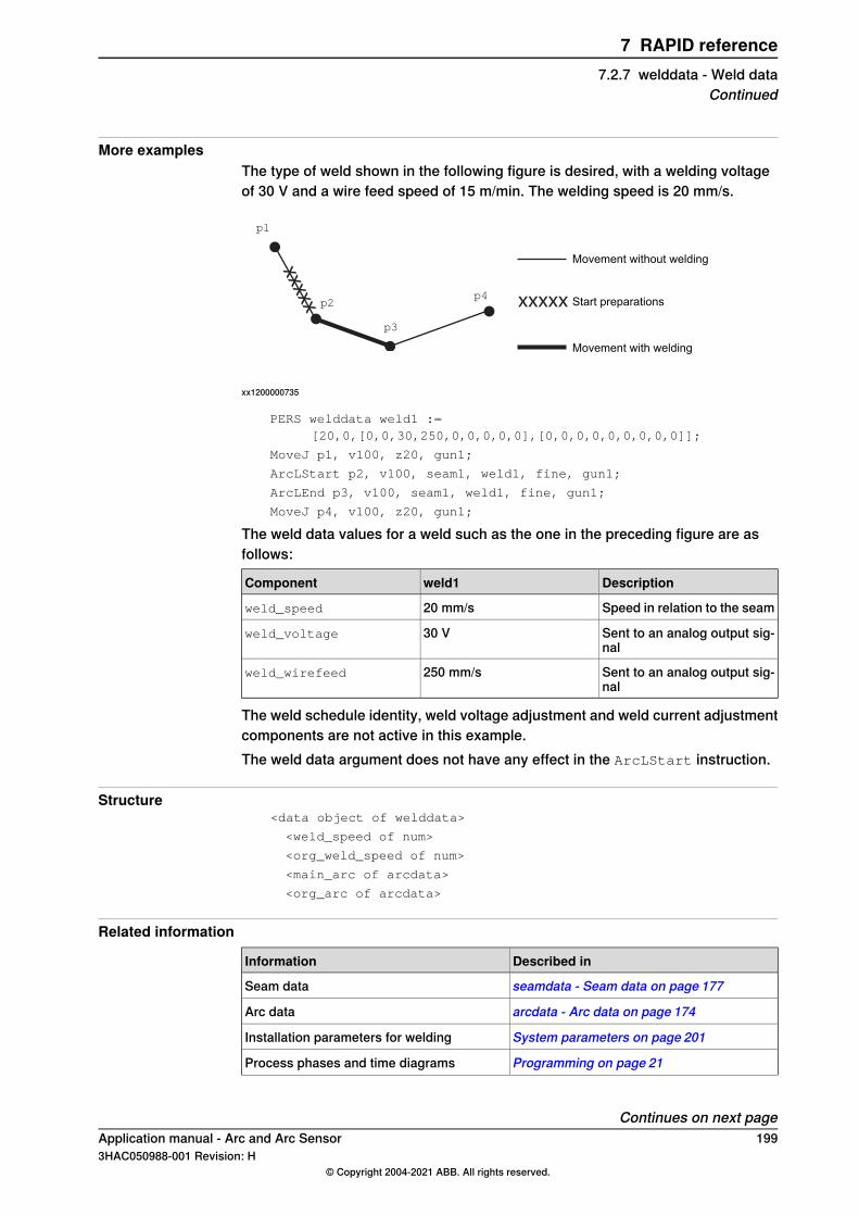
More examplesThe type of weld shown in the following figure is desired, with a welding voltageof 30 V and a wire feed speed of 15 m/min. The welding speed is 20 mm/s.
xxxxx xxxxx
p1
p2
p3
p4
Movement without welding
Movement with welding
Start preparations
xx1200000735
PERS welddata weld1 :=[20,0,[0,0,30,250,0,0,0,0,0],[0,0,0,0,0,0,0,0,0]];
MoveJ p1, v100, z20, gun1;
ArcLStart p2, v100, seam1, weld1, fine, gun1;
ArcLEnd p3, v100, seam1, weld1, fine, gun1;
MoveJ p4, v100, z20, gun1;
The weld data values for a weld such as the one in the preceding figure are asfollows:
Descriptionweld1Component
Speed in relation to the seam20 mm/sweld_speed
Sent to an analog output sig-nal
30 Vweld_voltage
Sent to an analog output sig-nal
250 mm/sweld_wirefeed
The weld schedule identity, weld voltage adjustment and weld current adjustmentcomponents are not active in this example.The weld data argument does not have any effect in the ArcLStart instruction.
Structure<data object of welddata>
<weld_speed of num>
<org_weld_speed of num>
<main_arc of arcdata>
<org_arc of arcdata>
Related information
Described inInformation
seamdata - Seam data on page 177Seam data
arcdata - Arc data on page 174Arc data
System parameters on page 201Installation parameters for welding
Programming on page 21Process phases and time diagrams
Continues on next pageApplication manual - Arc and Arc Sensor 1993HAC050988-001 Revision: H
© Copyright 2004-2021 ABB. All rights reserved.
7 RAPID reference7.2.7 welddata - Weld data
Continued
Described inInformation
ArcC, ArcC1, ArcC2 - Arc welding with circu-lar motion on page 107
Circular arc welding instructions
ArcL, ArcL1, ArcL2 - Arc welding with linearmotion on page 132
Linear arc welding instructions
200 Application manual - Arc and Arc Sensor3HAC050988-001 Revision: H
© Copyright 2004-2021 ABB. All rights reserved.
7 RAPID reference7.2.7 welddata - Weld dataContinued
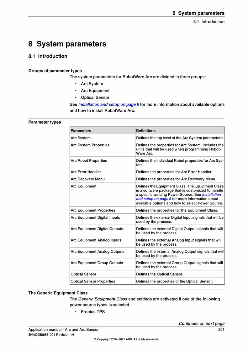
8 System parameters8.1 Introduction
Groups of parameter typesThe system parameters for RobotWare Arc are divided in three groups:
• Arc System• Arc Equipment• Optical Sensor
See Installation and setup on page 9 for more information about available optionsand how to install RobotWare Arc.
Parameter types
DefinitionsParameters
Defines the top level of the Arc System parameters.Arc System
Defines the properties for Arc System. Includes theunits that will be used when programming Robot-Ware Arc.
Arc System Properties
Defines the individual Robot properties for Arc Sys-tem.
Arc Robot Properties
Defines the properties for Arc Error Handler.Arc Error Handler
Defines the properties for Arc Recovery Menu.Arc Recovery Menu
Defines the Equipment Class. The Equipment Classis a software package that is customized to handlea specific welding Power Source. See Installationand setup on page 9 for more information aboutavailable options and how to select Power Source.
Arc Equipment
Defines the properties for the Equipment Class.Arc Equipment Properties
Defines the external Digital Input signals that will beused by the process.
Arc Equipment Digital Inputs
Defines the external Digital Output signals that willbe used by the process.
Arc Equipment Digital Outputs
Defines the external Analog Input signals that willbe used by the process.
Arc Equipment Analog Inputs
Defines the external Analog Output signals that willbe used by the process.
Arc Equipment Analog Outputs
Defines the external Group Output signals that willbe used by the process.
Arc Equipment Group Outputs
Defines the Optical Sensor.Optical Sensor
Defines the properties of the Optical Sensor.Optical Sensor Properties
The Generic Equipment ClassThe Generic Equipment Class and settings are activated if one of the followingpower source types is selected.
• Fronius TPS
Continues on next pageApplication manual - Arc and Arc Sensor 2013HAC050988-001 Revision: H
© Copyright 2004-2021 ABB. All rights reserved.
8 System parameters8.1 Introduction
• Standard I/O Welder• Simulated Welder
They all load the standard I/O equipment class that supports basic analog andschedule based welding.
Defining arc welding systemsUp to three arc welding systems can be activated simultaneously in the same robotinstallation. This may be required in the following sample cases:
• More than one piece of process equipment is connected• Two different electrode dimensions are used (different feeding systems must
be used for this to happen)• More than one process is used. For example, TIG and MIG/MAG.
If more than one arc welding system is defined, then a new set of instructions anddata types is activated for each system. The first additional system, which is definedby the sequence of defined system in a configuration file, is connected toinstructions and data types with the suffix 1, and the second to the suffix 2. Thatis, ArcL1 and ArcC1 would be connected to seamdata1, welddata1.
Configuration files
Note
Configuration files and backups shall not be loaded into systems running anolder RobotWare version than in which they were created.Configuration files and backups are not guaranteed to be compatible betweenmajor releases of RobotWare and may need to be migrated after a RobotWareupgrade.
202 Application manual - Arc and Arc Sensor3HAC050988-001 Revision: H
© Copyright 2004-2021 ABB. All rights reserved.
8 System parameters8.1 IntroductionContinued
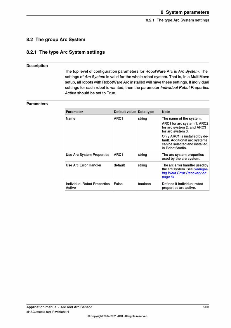
8.2 The group Arc System
8.2.1 The type Arc System settings
DescriptionThe top level of configuration parameters for RobotWare Arc is Arc System. Thesettings of Arc System is valid for the whole robot system. That is, in a MultiMovesetup, all robots with RobotWare Arc installed will have these settings. If individualsettings for each robot is wanted, then the parameter Individual Robot PropertiesActive should be set to True.
Parameters
NoteData typeDefault valueParameter
The name of the system.stringARC1NameARC1 for arc system 1, ARC2for arc system 2, and ARC3for arc system 3.Only ARC1 is installed by de-fault. Additional arc systemscan be selected and installed,in RobotStudio.
The arc system propertiesused by the arc system.
stringARC1Use Arc System Properties
The arc error handler used bythe arc system. SeeConfigur-ing Weld Error Recovery onpage 61.
stringdefaultUse Arc Error Handler
Defines if individual robotproperties are active.
booleanFalseIndividual Robot PropertiesActive
Application manual - Arc and Arc Sensor 2033HAC050988-001 Revision: H
© Copyright 2004-2021 ABB. All rights reserved.
8 System parameters8.2.1 The type Arc System settings
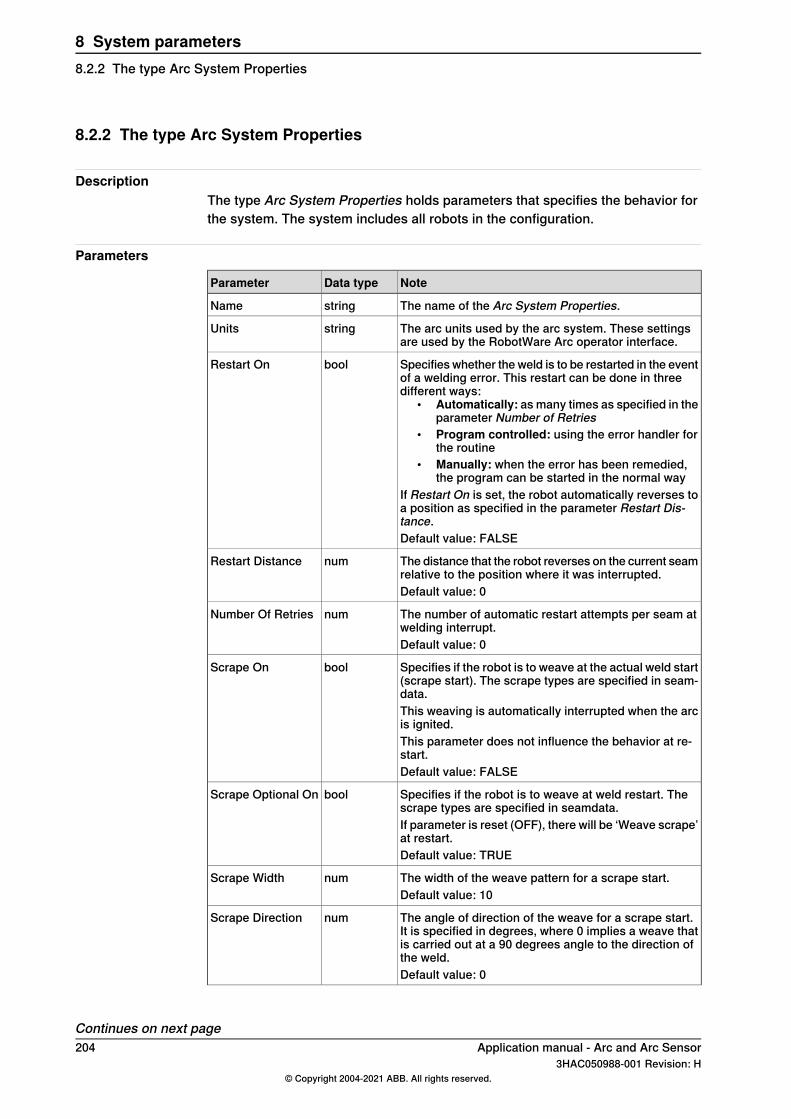
8.2.2 The type Arc System Properties
DescriptionThe type Arc System Properties holds parameters that specifies the behavior forthe system. The system includes all robots in the configuration.
Parameters
NoteData typeParameter
The name of the Arc System Properties.stringName
The arc units used by the arc system. These settingsare used by the RobotWare Arc operator interface.
stringUnits
Specifies whether the weld is to be restarted in the eventof a welding error. This restart can be done in threedifferent ways:
• Automatically: as many times as specified in theparameter Number of Retries
• Program controlled: using the error handler forthe routine
• Manually: when the error has been remedied,the program can be started in the normal way
If Restart On is set, the robot automatically reverses toa position as specified in the parameter Restart Dis-tance.
boolRestart On
Default value: FALSE
The distance that the robot reverses on the current seamrelative to the position where it was interrupted.
numRestart Distance
Default value: 0
The number of automatic restart attempts per seam atwelding interrupt.
numNumber Of Retries
Default value: 0
Specifies if the robot is to weave at the actual weld start(scrape start). The scrape types are specified in seam-data.
boolScrape On
This weaving is automatically interrupted when the arcis ignited.This parameter does not influence the behavior at re-start.Default value: FALSE
Specifies if the robot is to weave at weld restart. Thescrape types are specified in seamdata.
boolScrape Optional On
If parameter is reset (OFF), there will be ‘Weave scrape’at restart.Default value: TRUE
The width of the weave pattern for a scrape start.numScrape WidthDefault value: 10
The angle of direction of the weave for a scrape start.It is specified in degrees, where 0 implies a weave thatis carried out at a 90 degrees angle to the direction ofthe weld.
numScrape Direction
Default value: 0
Continues on next page204 Application manual - Arc and Arc Sensor
3HAC050988-001 Revision: H© Copyright 2004-2021 ABB. All rights reserved.
8 System parameters8.2.2 The type Arc System Properties
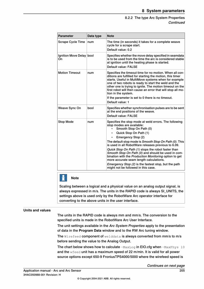
NoteData typeParameter
The time (in seconds) it takes for a complete weavecycle for a scrape start.
numScrape Cycle Time
Default value: 0.2
Specifies whether the move delay specified in seamdatais to be used from the time the arc is considered stableat ignition until the heating phase is started.
boolIgnition Move DelayOn
Default value: FALSE
Specifies the timeout time for no motion. When all con-ditions are fulfilled for starting the motion, this timerstarts. Useful in MultiMove systems when for exampleone of two robots is ready to start the weld and theother one is trying to ignite. The motion timeout on thefirst robot will then cause an error that will stop all mo-tion in the system.
numMotion Timeout
If the parameter is set to 0 there is no timeout.Default value: 1
Specifies whether synchronisation pulses are to be sentat the end positions of the weave.
boolWeave Sync On
Default value: FALSE
Specifies the stop mode at weld errors. The followingstop modes are available:
• Smooth Stop On Path (0)• Quick Stop On Path (1)• Emergency Stop (2)
The default stop mode is Smooth Stop On Path (0). Thisis used in all RobotWare releases previous to 6.09.
numStop Mode
Quick Stop On Path (1) stops the robot faster thanSmooth Stop On Path (0) and should be used in com-bination with the Production Monitoring option to getmore accurate seam length calculations.Emergency Stop (2) is the fastest stop, but the pathmight not be followed in this case.
Note
Scaling between a logical and a physical value on an analog output signal, isalways expressed in m/s. The units in the RAPID code is always SI_UNITS, thesettings above is used only by the RobotWare Arc operator interface forconverting to the above units in the user interface.
Units and valuesThe units in the RAPID code is always mm and mm/s. The conversion to thespecified units is made in the RobotWare Arc User Interface.The unit settings available in the Arc System Properties apply to the presentationof data in the Program Data window and to the RW Arc tuning window.The Wirefeed component of welddata is always converted from mm/s to m/sbefore sending the value to the Analog Output.The chart below shows how to calculate -MaxLog in EIO.cfg when -MaxPhys 10
and the wfeed unit has a maximum speed of 22 m/min. It is valid for all powersource options except 650-9 FroniusTPS4000/5000 where the wirefeed speed is
Continues on next pageApplication manual - Arc and Arc Sensor 2053HAC050988-001 Revision: H
© Copyright 2004-2021 ABB. All rights reserved.
8 System parameters8.2.2 The type Arc System Properties
Continued
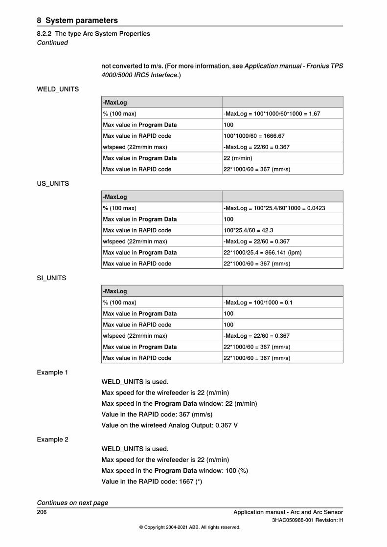
not converted to m/s. (For more information, see Applicationmanual - Fronius TPS4000/5000 IRC5 Interface.)
WELD_UNITS
-MaxLog
-MaxLog = 100*1000/60*1000 = 1.67% (100 max)
100Max value in Program Data
100*1000/60 = 1666.67Max value in RAPID code
-MaxLog = 22/60 = 0.367wfspeed (22m/min max)
22 (m/min)Max value in Program Data
22*1000/60 = 367 (mm/s)Max value in RAPID code
US_UNITS
-MaxLog
-MaxLog = 100*25.4/60*1000 = 0.0423% (100 max)
100Max value in Program Data
100*25.4/60 = 42.3Max value in RAPID code
-MaxLog = 22/60 = 0.367wfspeed (22m/min max)
22*1000/25.4 = 866.141 (ipm)Max value in Program Data
22*1000/60 = 367 (mm/s)Max value in RAPID code
SI_UNITS
-MaxLog
-MaxLog = 100/1000 = 0.1% (100 max)
100Max value in Program Data
100Max value in RAPID code
-MaxLog = 22/60 = 0.367wfspeed (22m/min max)
22*1000/60 = 367 (mm/s)Max value in Program Data
22*1000/60 = 367 (mm/s)Max value in RAPID code
Example 1WELD_UNITS is used.Max speed for the wirefeeder is 22 (m/min)Max speed in the Program Data window: 22 (m/min)Value in the RAPID code: 367 (mm/s)Value on the wirefeed Analog Output: 0.367 V
Example 2WELD_UNITS is used.Max speed for the wirefeeder is 22 (m/min)Max speed in the Program Data window: 100 (%)Value in the RAPID code: 1667 (*)
Continues on next page206 Application manual - Arc and Arc Sensor
3HAC050988-001 Revision: H© Copyright 2004-2021 ABB. All rights reserved.
8 System parameters8.2.2 The type Arc System PropertiesContinued

Value on the wirefeed Analog Output: 1.67 VThe * indicates that the % value is converted according to WELD_UNITS, which inthis case does not give a very useful value. Therefore, if wirefeed is expressed as%, we recommend using SI_UNITS.
Application manual - Arc and Arc Sensor 2073HAC050988-001 Revision: H
© Copyright 2004-2021 ABB. All rights reserved.
8 System parameters8.2.2 The type Arc System Properties
Continued
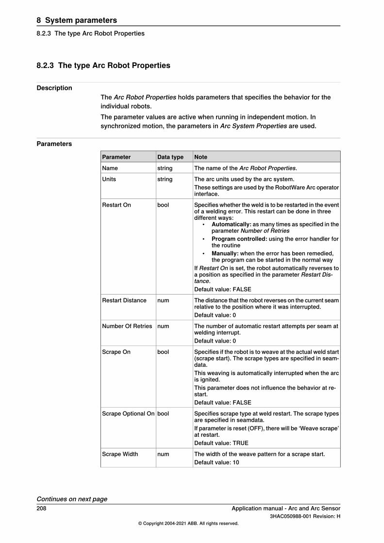
8.2.3 The type Arc Robot Properties
DescriptionThe Arc Robot Properties holds parameters that specifies the behavior for theindividual robots.The parameter values are active when running in independent motion. Insynchronized motion, the parameters in Arc System Properties are used.
Parameters
NoteData typeParameter
The name of the Arc Robot Properties.stringName
The arc units used by the arc system.stringUnitsThese settings are used by the RobotWare Arc operatorinterface.
Specifies whether the weld is to be restarted in the eventof a welding error. This restart can be done in threedifferent ways:
• Automatically: as many times as specified in theparameter Number of Retries
• Program controlled: using the error handler forthe routine
• Manually: when the error has been remedied,the program can be started in the normal way
If Restart On is set, the robot automatically reverses toa position as specified in the parameter Restart Dis-tance.
boolRestart On
Default value: FALSE
The distance that the robot reverses on the current seamrelative to the position where it was interrupted.
numRestart Distance
Default value: 0
The number of automatic restart attempts per seam atwelding interrupt.
numNumber Of Retries
Default value: 0
Specifies if the robot is to weave at the actual weld start(scrape start). The scrape types are specified in seam-data.
boolScrape On
This weaving is automatically interrupted when the arcis ignited.This parameter does not influence the behavior at re-start.Default value: FALSE
Specifies scrape type at weld restart. The scrape typesare specified in seamdata.
boolScrape Optional On
If parameter is reset (OFF), there will be ‘Weave scrape’at restart.Default value: TRUE
The width of the weave pattern for a scrape start.numScrape WidthDefault value: 10
Continues on next page208 Application manual - Arc and Arc Sensor
3HAC050988-001 Revision: H© Copyright 2004-2021 ABB. All rights reserved.
8 System parameters8.2.3 The type Arc Robot Properties
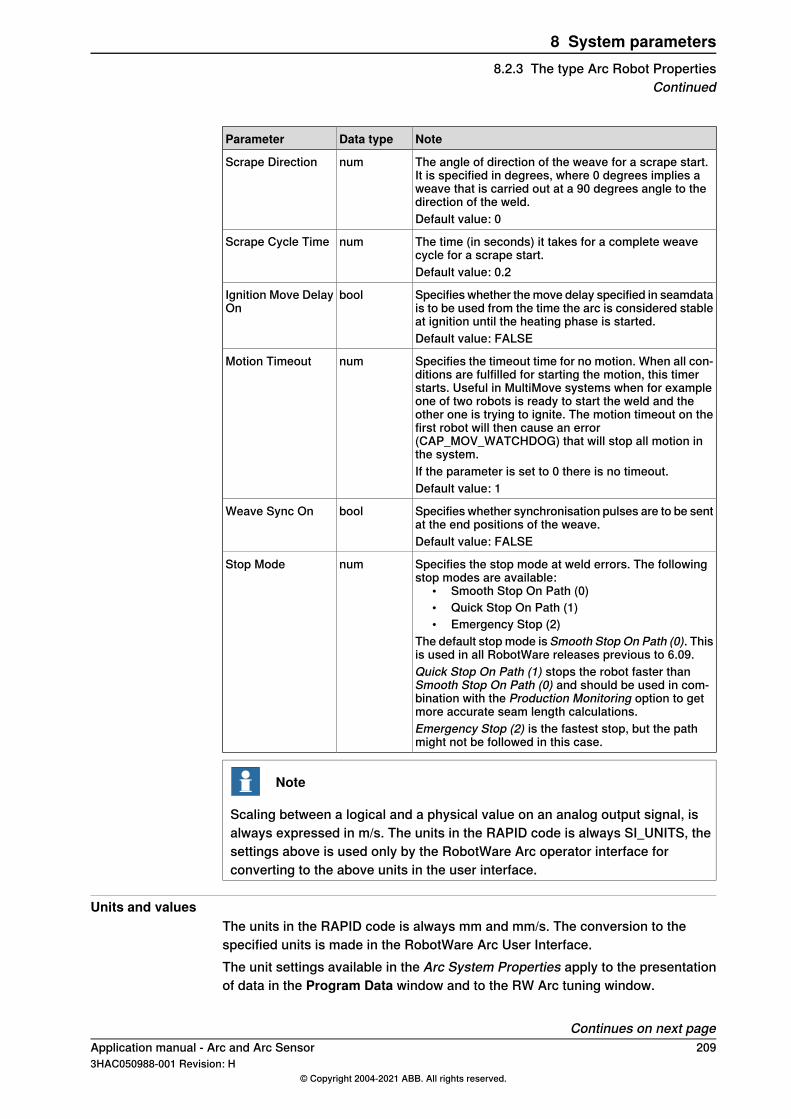
NoteData typeParameter
The angle of direction of the weave for a scrape start.It is specified in degrees, where 0 degrees implies aweave that is carried out at a 90 degrees angle to thedirection of the weld.
numScrape Direction
Default value: 0
The time (in seconds) it takes for a complete weavecycle for a scrape start.
numScrape Cycle Time
Default value: 0.2
Specifies whether the move delay specified in seamdatais to be used from the time the arc is considered stableat ignition until the heating phase is started.
boolIgnition Move DelayOn
Default value: FALSE
Specifies the timeout time for no motion. When all con-ditions are fulfilled for starting the motion, this timerstarts. Useful in MultiMove systems when for exampleone of two robots is ready to start the weld and theother one is trying to ignite. The motion timeout on thefirst robot will then cause an error(CAP_MOV_WATCHDOG) that will stop all motion inthe system.
numMotion Timeout
If the parameter is set to 0 there is no timeout.Default value: 1
Specifies whether synchronisation pulses are to be sentat the end positions of the weave.
boolWeave Sync On
Default value: FALSE
Specifies the stop mode at weld errors. The followingstop modes are available:
• Smooth Stop On Path (0)• Quick Stop On Path (1)• Emergency Stop (2)
The default stop mode is Smooth Stop On Path (0). Thisis used in all RobotWare releases previous to 6.09.
numStop Mode
Quick Stop On Path (1) stops the robot faster thanSmooth Stop On Path (0) and should be used in com-bination with the Production Monitoring option to getmore accurate seam length calculations.Emergency Stop (2) is the fastest stop, but the pathmight not be followed in this case.
Note
Scaling between a logical and a physical value on an analog output signal, isalways expressed in m/s. The units in the RAPID code is always SI_UNITS, thesettings above is used only by the RobotWare Arc operator interface forconverting to the above units in the user interface.
Units and valuesThe units in the RAPID code is always mm and mm/s. The conversion to thespecified units is made in the RobotWare Arc User Interface.The unit settings available in the Arc System Properties apply to the presentationof data in the Program Data window and to the RW Arc tuning window.
Continues on next pageApplication manual - Arc and Arc Sensor 2093HAC050988-001 Revision: H
© Copyright 2004-2021 ABB. All rights reserved.
8 System parameters8.2.3 The type Arc Robot Properties
Continued
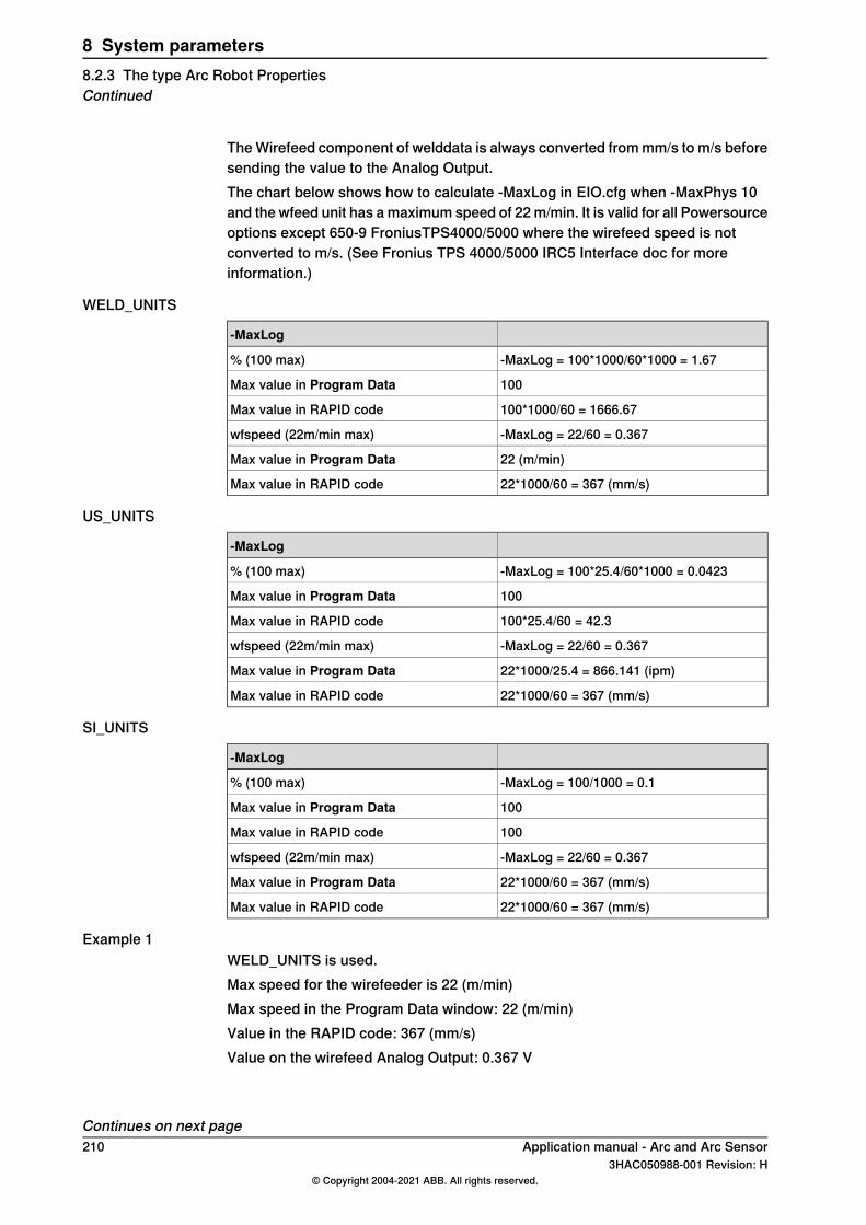
The Wirefeed component of welddata is always converted from mm/s to m/s beforesending the value to the Analog Output.The chart below shows how to calculate -MaxLog in EIO.cfg when -MaxPhys 10and the wfeed unit has a maximum speed of 22 m/min. It is valid for all Powersourceoptions except 650-9 FroniusTPS4000/5000 where the wirefeed speed is notconverted to m/s. (See Fronius TPS 4000/5000 IRC5 Interface doc for moreinformation.)
WELD_UNITS
-MaxLog
-MaxLog = 100*1000/60*1000 = 1.67% (100 max)
100Max value in Program Data
100*1000/60 = 1666.67Max value in RAPID code
-MaxLog = 22/60 = 0.367wfspeed (22m/min max)
22 (m/min)Max value in Program Data
22*1000/60 = 367 (mm/s)Max value in RAPID code
US_UNITS
-MaxLog
-MaxLog = 100*25.4/60*1000 = 0.0423% (100 max)
100Max value in Program Data
100*25.4/60 = 42.3Max value in RAPID code
-MaxLog = 22/60 = 0.367wfspeed (22m/min max)
22*1000/25.4 = 866.141 (ipm)Max value in Program Data
22*1000/60 = 367 (mm/s)Max value in RAPID code
SI_UNITS
-MaxLog
-MaxLog = 100/1000 = 0.1% (100 max)
100Max value in Program Data
100Max value in RAPID code
-MaxLog = 22/60 = 0.367wfspeed (22m/min max)
22*1000/60 = 367 (mm/s)Max value in Program Data
22*1000/60 = 367 (mm/s)Max value in RAPID code
Example 1WELD_UNITS is used.Max speed for the wirefeeder is 22 (m/min)Max speed in the Program Data window: 22 (m/min)Value in the RAPID code: 367 (mm/s)Value on the wirefeed Analog Output: 0.367 V
Continues on next page210 Application manual - Arc and Arc Sensor
3HAC050988-001 Revision: H© Copyright 2004-2021 ABB. All rights reserved.
8 System parameters8.2.3 The type Arc Robot PropertiesContinued
Example 2WELD_UNITS is used.Max speed for the wirefeeder is 22 (m/min)Max speed in the Program Data window: 100 (%)Value in the RAPID code: 1667 (*)Value on the wirefeed Analog Output: 1.67 VThe * indicates that the % value is converted according to WELD_UNITS, which inthis case does not give a very useful value. Therefore, if wirefeed is expressed as%, it is recommended to use SI_UNITS.
Application manual - Arc and Arc Sensor 2113HAC050988-001 Revision: H
© Copyright 2004-2021 ABB. All rights reserved.
8 System parameters8.2.3 The type Arc Robot Properties
Continued
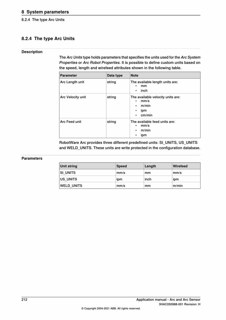
8.2.4 The type Arc Units
DescriptionTheArc Units type holds parameters that specifies the units used for theArc SystemProperties or Arc Robot Properties. It is possible to define custom units based onthe speed, length and wirefeed attributes shown in the following table.
NoteData typeParameter
The available length units are:• mm• inch
stringArc Length unit
The available velocity units are:• mm/s• m/min• ipm• cm/min
stringArc Velocity unit
The available feed units are:• mm/s• m/min• ipm
stringArc Feed unit
RobotWare Arc provides three different predefined units: SI_UNITS, US_UNITSand WELD_UNITS. These units are write protected in the configuration database.
Parameters
WirefeedLengthSpeedUnit string
mm/smmmm/sSI_UNITS
ipminchipmUS_UNITS
m/minmmmm/sWELD_UNITS
212 Application manual - Arc and Arc Sensor3HAC050988-001 Revision: H
© Copyright 2004-2021 ABB. All rights reserved.
8 System parameters8.2.4 The type Arc Units
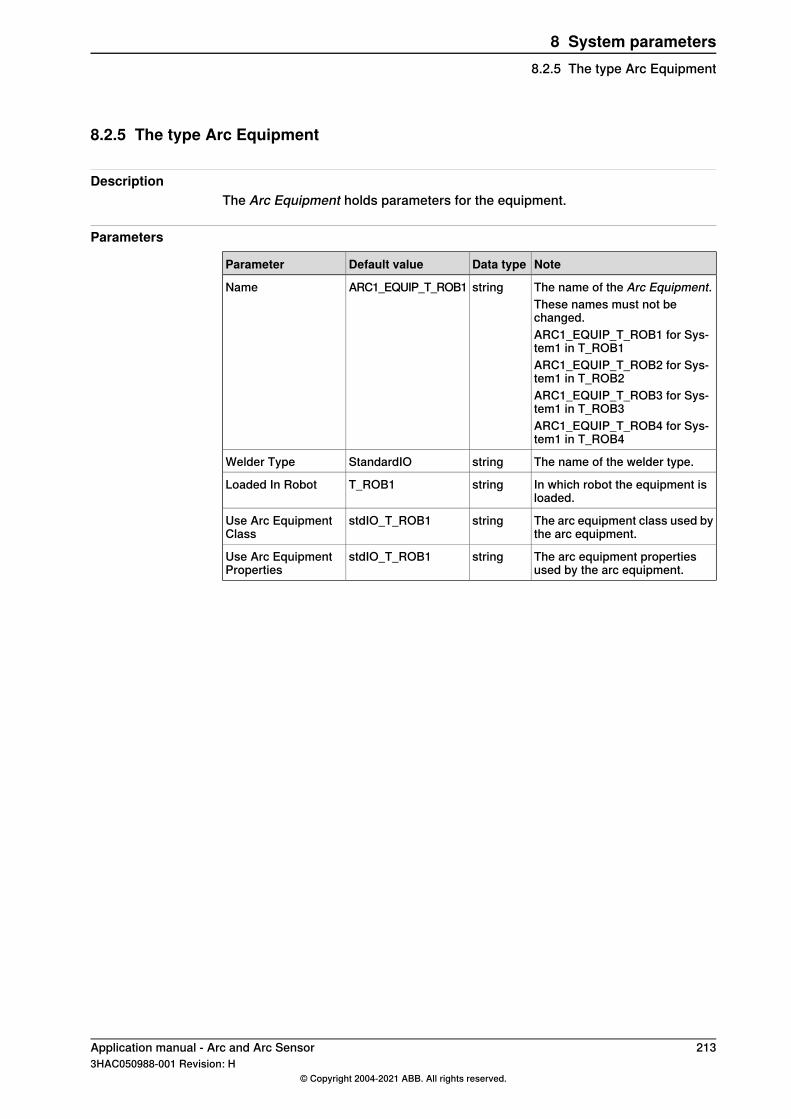
8.2.5 The type Arc Equipment
DescriptionThe Arc Equipment holds parameters for the equipment.
Parameters
NoteData typeDefault valueParameter
The name of the Arc Equipment.stringARC1_EQUIP_T_ROB1NameThese names must not bechanged.ARC1_EQUIP_T_ROB1 for Sys-tem1 in T_ROB1ARC1_EQUIP_T_ROB2 for Sys-tem1 in T_ROB2ARC1_EQUIP_T_ROB3 for Sys-tem1 in T_ROB3ARC1_EQUIP_T_ROB4 for Sys-tem1 in T_ROB4
The name of the welder type.stringStandardIOWelder Type
In which robot the equipment isloaded.
stringT_ROB1Loaded In Robot
The arc equipment class used bythe arc equipment.
stringstdIO_T_ROB1Use Arc EquipmentClass
The arc equipment propertiesused by the arc equipment.
stringstdIO_T_ROB1Use Arc EquipmentProperties
Application manual - Arc and Arc Sensor 2133HAC050988-001 Revision: H
© Copyright 2004-2021 ABB. All rights reserved.
8 System parameters8.2.5 The type Arc Equipment
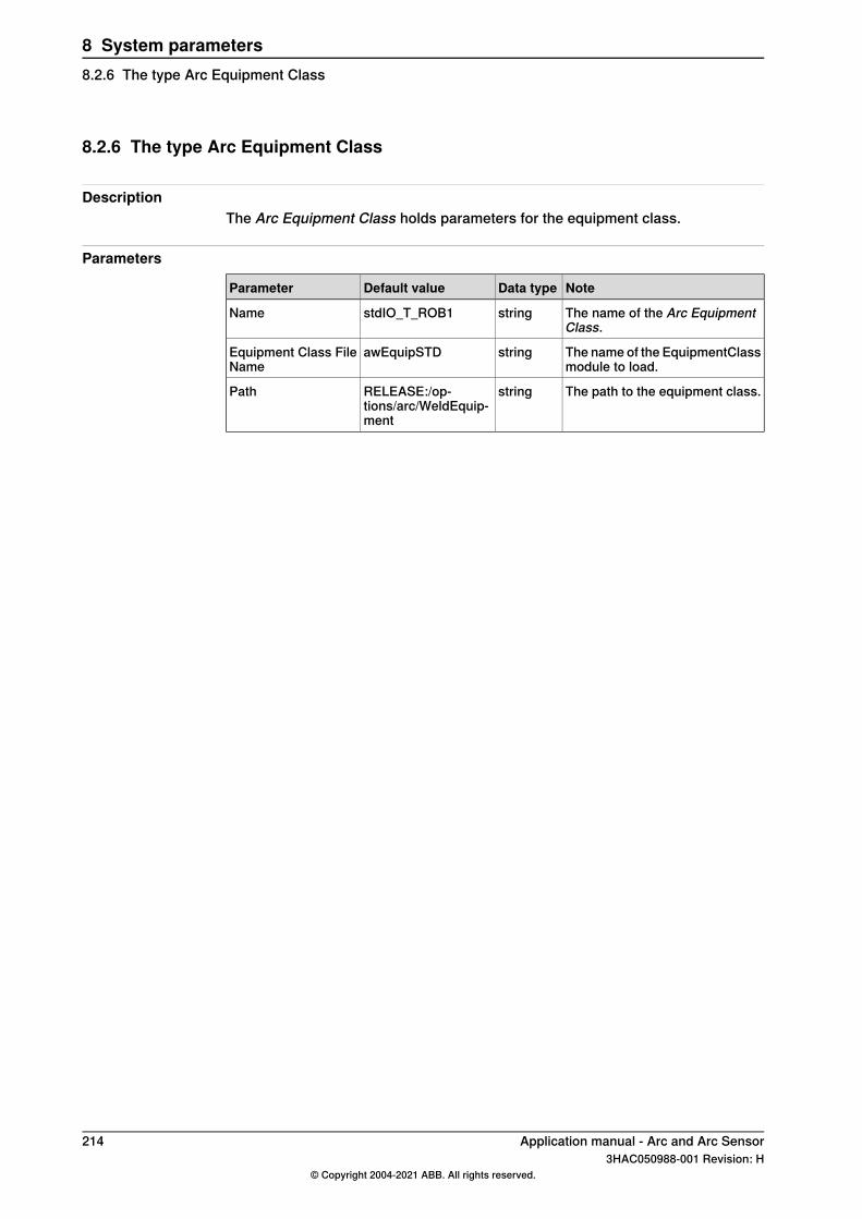
8.2.6 The type Arc Equipment Class
DescriptionThe Arc Equipment Class holds parameters for the equipment class.
Parameters
NoteData typeDefault valueParameter
The name of the Arc EquipmentClass.
stringstdIO_T_ROB1Name
The name of the EquipmentClassmodule to load.
stringawEquipSTDEquipment Class FileName
The path to the equipment class.stringRELEASE:/op-tions/arc/WeldEquip-ment
Path
214 Application manual - Arc and Arc Sensor3HAC050988-001 Revision: H
© Copyright 2004-2021 ABB. All rights reserved.
8 System parameters8.2.6 The type Arc Equipment Class
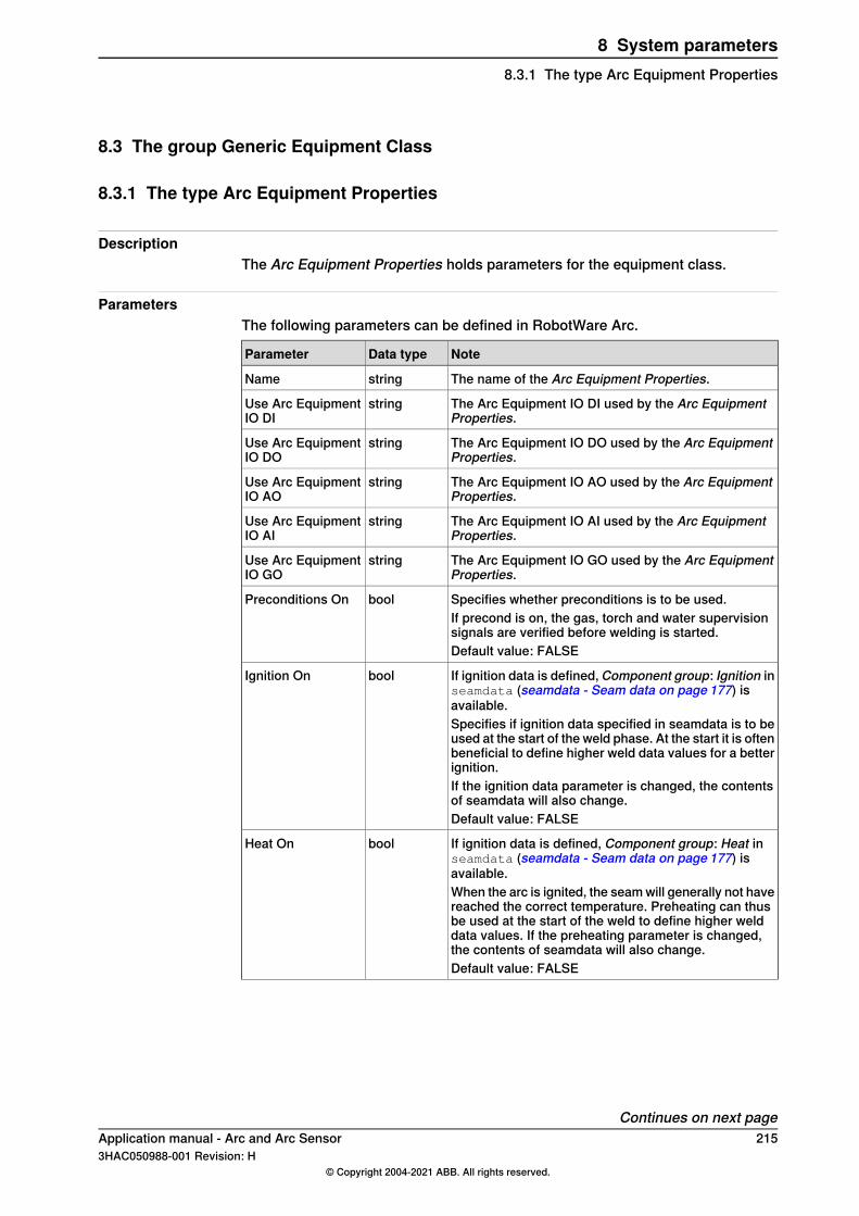
8.3 The group Generic Equipment Class
8.3.1 The type Arc Equipment Properties
DescriptionThe Arc Equipment Properties holds parameters for the equipment class.
ParametersThe following parameters can be defined in RobotWare Arc.
NoteData typeParameter
The name of the Arc Equipment Properties.stringName
The Arc Equipment IO DI used by the Arc EquipmentProperties.
stringUse Arc EquipmentIO DI
The Arc Equipment IO DO used by the Arc EquipmentProperties.
stringUse Arc EquipmentIO DO
The Arc Equipment IO AO used by the Arc EquipmentProperties.
stringUse Arc EquipmentIO AO
The Arc Equipment IO AI used by the Arc EquipmentProperties.
stringUse Arc EquipmentIO AI
The Arc Equipment IO GO used by the Arc EquipmentProperties.
stringUse Arc EquipmentIO GO
Specifies whether preconditions is to be used.boolPreconditions OnIf precond is on, the gas, torch and water supervisionsignals are verified before welding is started.Default value: FALSE
If ignition data is defined, Component group: Ignition inseamdata (seamdata - Seam data on page 177) isavailable.
boolIgnition On
Specifies if ignition data specified in seamdata is to beused at the start of the weld phase. At the start it is oftenbeneficial to define higher weld data values for a betterignition.If the ignition data parameter is changed, the contentsof seamdata will also change.Default value: FALSE
If ignition data is defined, Component group: Heat inseamdata (seamdata - Seam data on page 177) isavailable.
boolHeat On
When the arc is ignited, the seam will generally not havereached the correct temperature. Preheating can thusbe used at the start of the weld to define higher welddata values. If the preheating parameter is changed,the contents of seamdata will also change.Default value: FALSE
Continues on next pageApplication manual - Arc and Arc Sensor 2153HAC050988-001 Revision: H
© Copyright 2004-2021 ABB. All rights reserved.
8 System parameters8.3.1 The type Arc Equipment Properties
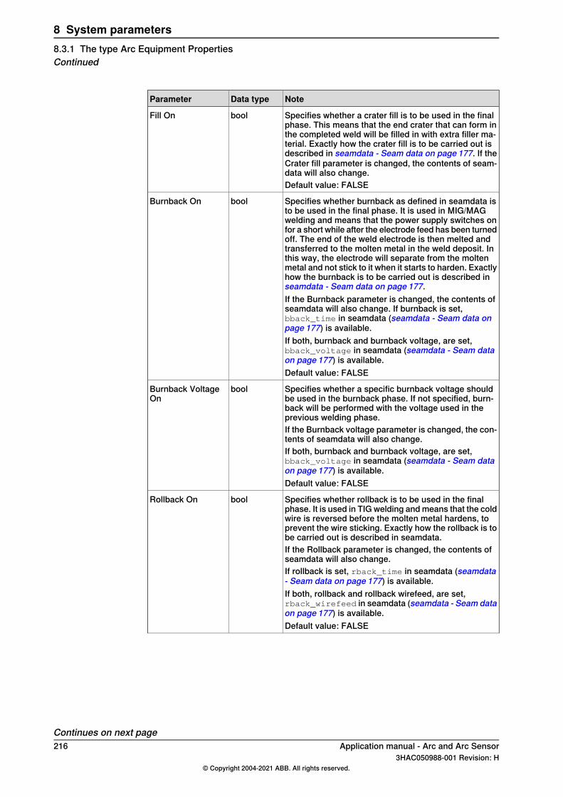
NoteData typeParameter
Specifies whether a crater fill is to be used in the finalphase. This means that the end crater that can form inthe completed weld will be filled in with extra filler ma-terial. Exactly how the crater fill is to be carried out isdescribed in seamdata - Seam data on page 177. If theCrater fill parameter is changed, the contents of seam-data will also change.
boolFill On
Default value: FALSE
Specifies whether burnback as defined in seamdata isto be used in the final phase. It is used in MIG/MAGwelding and means that the power supply switches onfor a short while after the electrode feed has been turnedoff. The end of the weld electrode is then melted andtransferred to the molten metal in the weld deposit. Inthis way, the electrode will separate from the moltenmetal and not stick to it when it starts to harden. Exactlyhow the burnback is to be carried out is described inseamdata - Seam data on page 177.
boolBurnback On
If the Burnback parameter is changed, the contents ofseamdata will also change. If burnback is set,bback_time in seamdata (seamdata - Seam data onpage 177) is available.If both, burnback and burnback voltage, are set,bback_voltage in seamdata (seamdata - Seam dataon page 177) is available.Default value: FALSE
Specifies whether a specific burnback voltage shouldbe used in the burnback phase. If not specified, burn-back will be performed with the voltage used in theprevious welding phase.
boolBurnback VoltageOn
If the Burnback voltage parameter is changed, the con-tents of seamdata will also change.If both, burnback and burnback voltage, are set,bback_voltage in seamdata (seamdata - Seam dataon page 177) is available.Default value: FALSE
Specifies whether rollback is to be used in the finalphase. It is used in TIG welding and means that the coldwire is reversed before the molten metal hardens, toprevent the wire sticking. Exactly how the rollback is tobe carried out is described in seamdata.
boolRollback On
If the Rollback parameter is changed, the contents ofseamdata will also change.If rollback is set, rback_time in seamdata (seamdata- Seam data on page 177) is available.If both, rollback and rollback wirefeed, are set,rback_wirefeed in seamdata (seamdata - Seam dataon page 177) is available.Default value: FALSE
Continues on next page216 Application manual - Arc and Arc Sensor
3HAC050988-001 Revision: H© Copyright 2004-2021 ABB. All rights reserved.
8 System parameters8.3.1 The type Arc Equipment PropertiesContinued
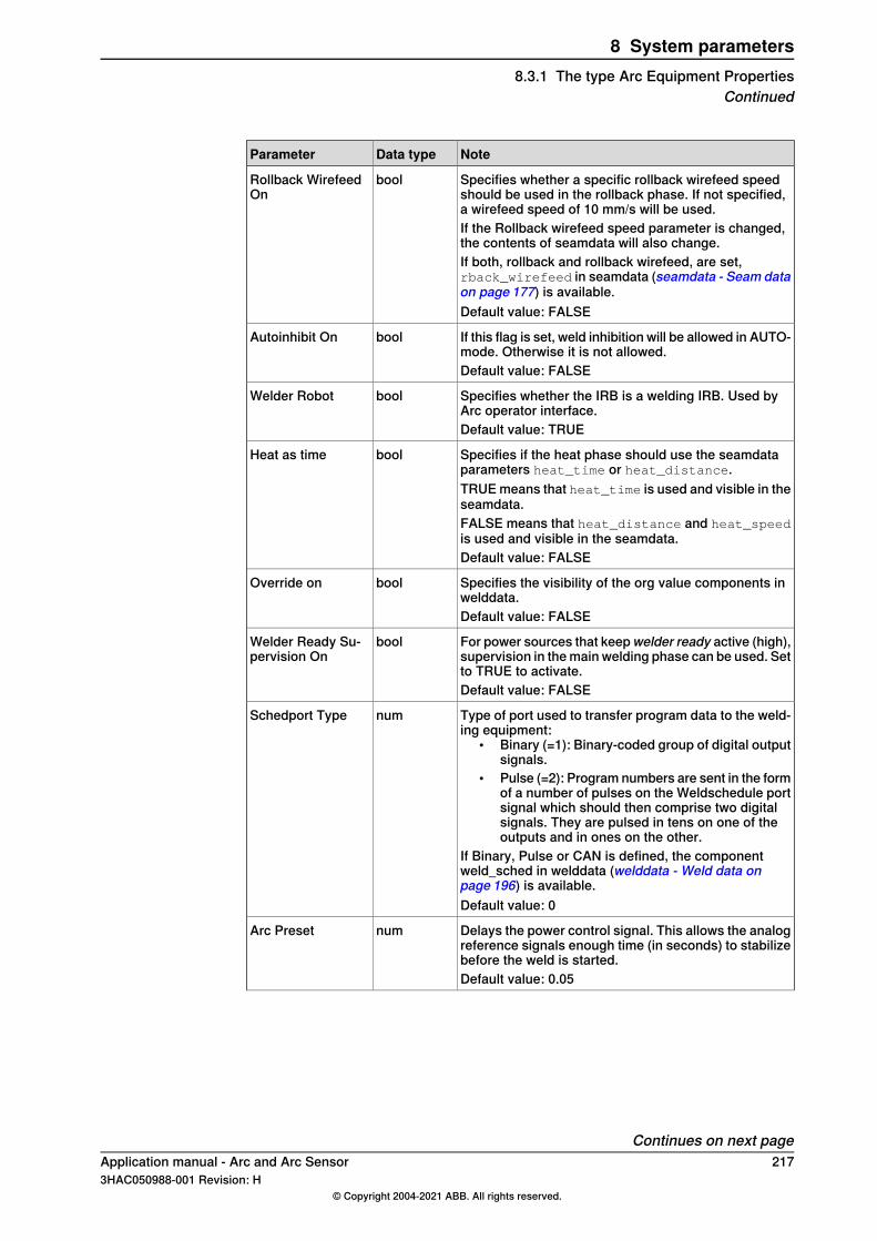
NoteData typeParameter
Specifies whether a specific rollback wirefeed speedshould be used in the rollback phase. If not specified,a wirefeed speed of 10 mm/s will be used.
boolRollback WirefeedOn
If the Rollback wirefeed speed parameter is changed,the contents of seamdata will also change.If both, rollback and rollback wirefeed, are set,rback_wirefeed in seamdata (seamdata - Seam dataon page 177) is available.Default value: FALSE
If this flag is set, weld inhibition will be allowed in AUTO-mode. Otherwise it is not allowed.
boolAutoinhibit On
Default value: FALSE
Specifies whether the IRB is a welding IRB. Used byArc operator interface.
boolWelder Robot
Default value: TRUE
Specifies if the heat phase should use the seamdataparameters heat_time or heat_distance.
boolHeat as time
TRUE means that heat_time is used and visible in theseamdata.FALSE means that heat_distance and heat_speedis used and visible in the seamdata.Default value: FALSE
Specifies the visibility of the org value components inwelddata.
boolOverride on
Default value: FALSE
For power sources that keep welder ready active (high),supervision in the main welding phase can be used. Setto TRUE to activate.
boolWelder Ready Su-pervision On
Default value: FALSE
Type of port used to transfer program data to the weld-ing equipment:
• Binary (=1): Binary-coded group of digital outputsignals.
• Pulse (=2): Program numbers are sent in the formof a number of pulses on the Weldschedule portsignal which should then comprise two digitalsignals. They are pulsed in tens on one of theoutputs and in ones on the other.
If Binary, Pulse or CAN is defined, the componentweld_sched in welddata (welddata - Weld data onpage 196) is available.
numSchedport Type
Default value: 0
Delays the power control signal. This allows the analogreference signals enough time (in seconds) to stabilizebefore the weld is started.
numArc Preset
Default value: 0.05
Continues on next pageApplication manual - Arc and Arc Sensor 2173HAC050988-001 Revision: H
© Copyright 2004-2021 ABB. All rights reserved.
8 System parameters8.3.1 The type Arc Equipment Properties
Continued
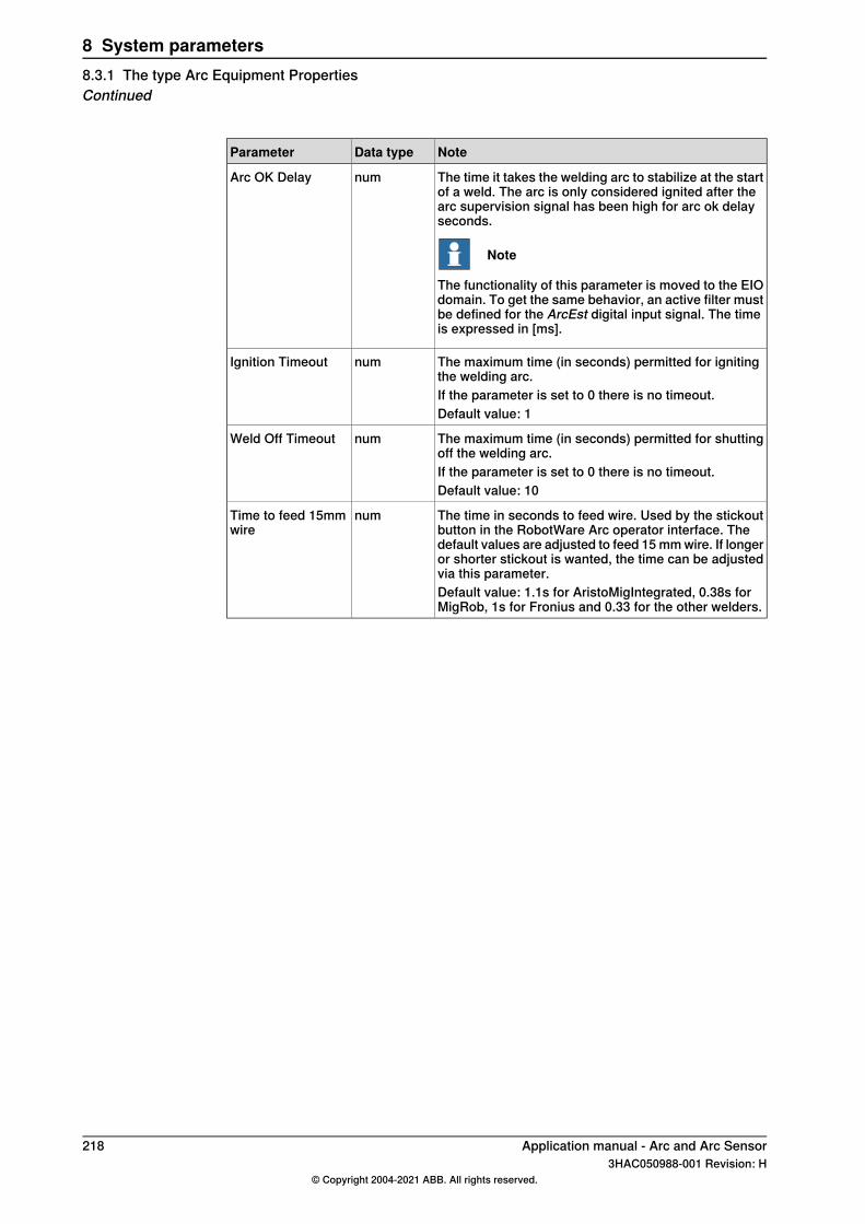
NoteData typeParameter
The time it takes the welding arc to stabilize at the startof a weld. The arc is only considered ignited after thearc supervision signal has been high for arc ok delayseconds.
Note
The functionality of this parameter is moved to the EIOdomain. To get the same behavior, an active filter mustbe defined for the ArcEst digital input signal. The timeis expressed in [ms].
numArc OK Delay
The maximum time (in seconds) permitted for ignitingthe welding arc.
numIgnition Timeout
If the parameter is set to 0 there is no timeout.Default value: 1
The maximum time (in seconds) permitted for shuttingoff the welding arc.
numWeld Off Timeout
If the parameter is set to 0 there is no timeout.Default value: 10
The time in seconds to feed wire. Used by the stickoutbutton in the RobotWare Arc operator interface. Thedefault values are adjusted to feed 15 mm wire. If longeror shorter stickout is wanted, the time can be adjustedvia this parameter.
numTime to feed 15mmwire
Default value: 1.1s for AristoMigIntegrated, 0.38s forMigRob, 1s for Fronius and 0.33 for the other welders.
218 Application manual - Arc and Arc Sensor3HAC050988-001 Revision: H
© Copyright 2004-2021 ABB. All rights reserved.
8 System parameters8.3.1 The type Arc Equipment PropertiesContinued
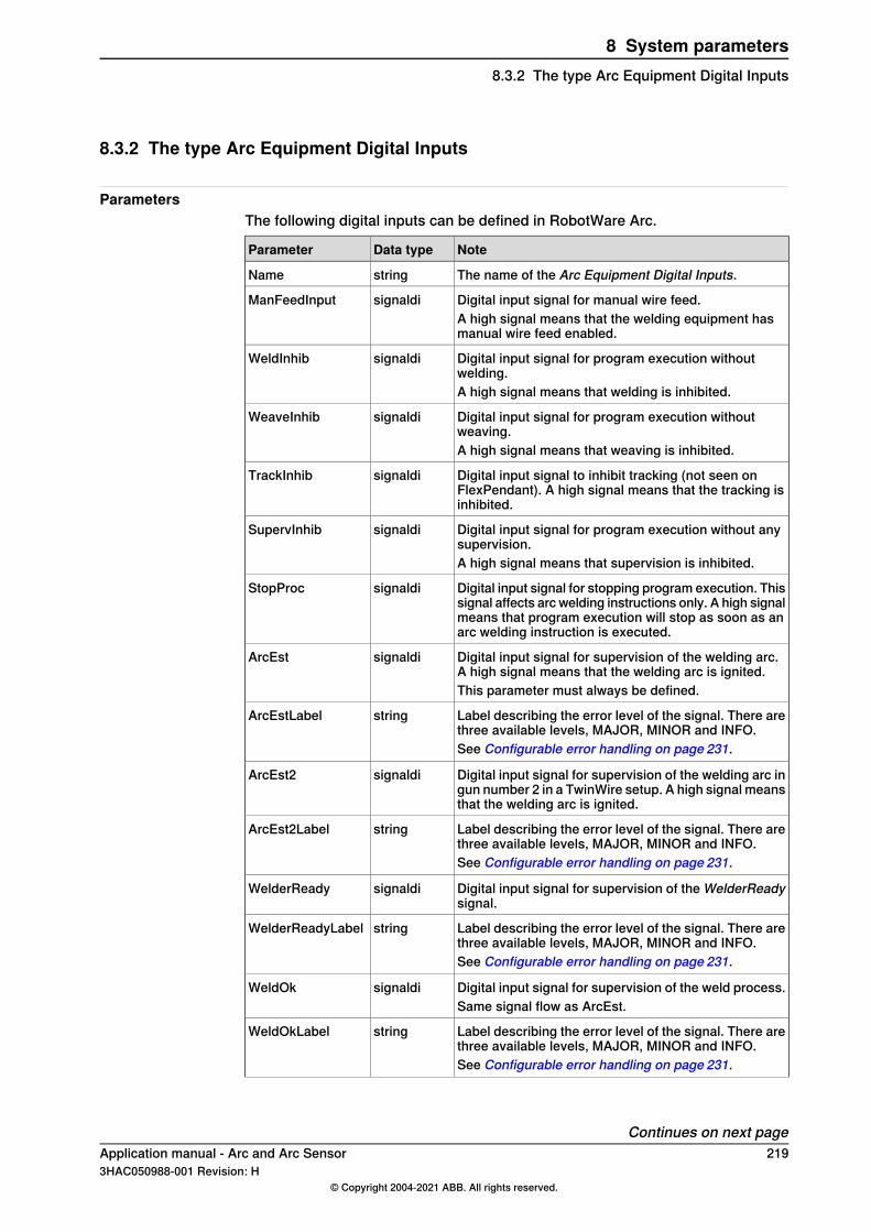
8.3.2 The type Arc Equipment Digital Inputs
ParametersThe following digital inputs can be defined in RobotWare Arc.
NoteData typeParameter
The name of the Arc Equipment Digital Inputs.stringName
Digital input signal for manual wire feed.signaldiManFeedInputA high signal means that the welding equipment hasmanual wire feed enabled.
Digital input signal for program execution withoutwelding.
signaldiWeldInhib
A high signal means that welding is inhibited.
Digital input signal for program execution withoutweaving.
signaldiWeaveInhib
A high signal means that weaving is inhibited.
Digital input signal to inhibit tracking (not seen onFlexPendant). A high signal means that the tracking isinhibited.
signaldiTrackInhib
Digital input signal for program execution without anysupervision.
signaldiSupervInhib
A high signal means that supervision is inhibited.
Digital input signal for stopping program execution. Thissignal affects arc welding instructions only. A high signalmeans that program execution will stop as soon as anarc welding instruction is executed.
signaldiStopProc
Digital input signal for supervision of the welding arc.A high signal means that the welding arc is ignited.
signaldiArcEst
This parameter must always be defined.
Label describing the error level of the signal. There arethree available levels, MAJOR, MINOR and INFO.
stringArcEstLabel
See Configurable error handling on page 231.
Digital input signal for supervision of the welding arc ingun number 2 in a TwinWire setup. A high signal meansthat the welding arc is ignited.
signaldiArcEst2
Label describing the error level of the signal. There arethree available levels, MAJOR, MINOR and INFO.
stringArcEst2Label
See Configurable error handling on page 231.
Digital input signal for supervision of the WelderReadysignal.
signaldiWelderReady
Label describing the error level of the signal. There arethree available levels, MAJOR, MINOR and INFO.
stringWelderReadyLabel
See Configurable error handling on page 231.
Digital input signal for supervision of the weld process.signaldiWeldOkSame signal flow as ArcEst.
Label describing the error level of the signal. There arethree available levels, MAJOR, MINOR and INFO.
stringWeldOkLabel
See Configurable error handling on page 231.
Continues on next pageApplication manual - Arc and Arc Sensor 2193HAC050988-001 Revision: H
© Copyright 2004-2021 ABB. All rights reserved.
8 System parameters8.3.2 The type Arc Equipment Digital Inputs
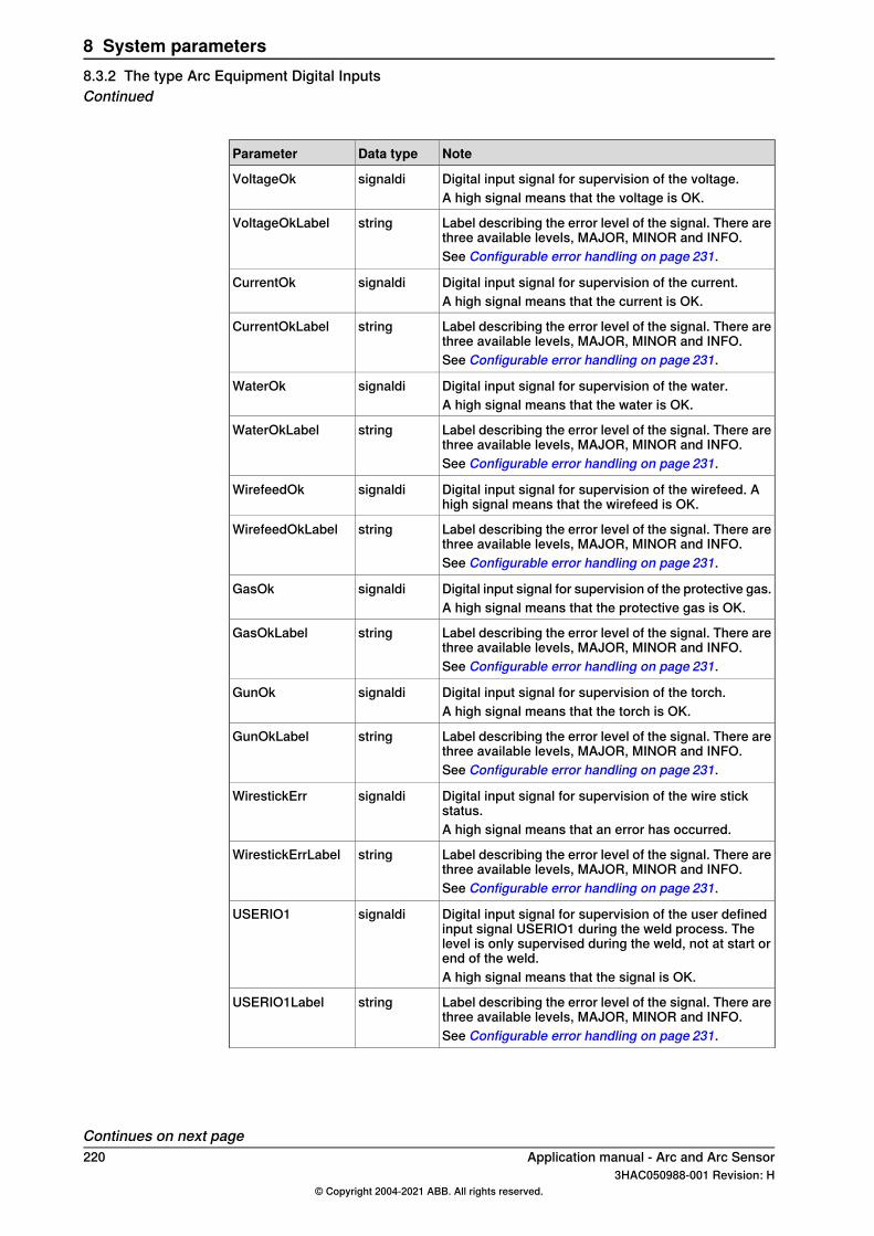
NoteData typeParameter
Digital input signal for supervision of the voltage.signaldiVoltageOkA high signal means that the voltage is OK.
Label describing the error level of the signal. There arethree available levels, MAJOR, MINOR and INFO.
stringVoltageOkLabel
See Configurable error handling on page 231.
Digital input signal for supervision of the current.signaldiCurrentOkA high signal means that the current is OK.
Label describing the error level of the signal. There arethree available levels, MAJOR, MINOR and INFO.
stringCurrentOkLabel
See Configurable error handling on page 231.
Digital input signal for supervision of the water.signaldiWaterOkA high signal means that the water is OK.
Label describing the error level of the signal. There arethree available levels, MAJOR, MINOR and INFO.
stringWaterOkLabel
See Configurable error handling on page 231.
Digital input signal for supervision of the wirefeed. Ahigh signal means that the wirefeed is OK.
signaldiWirefeedOk
Label describing the error level of the signal. There arethree available levels, MAJOR, MINOR and INFO.
stringWirefeedOkLabel
See Configurable error handling on page 231.
Digital input signal for supervision of the protective gas.signaldiGasOkA high signal means that the protective gas is OK.
Label describing the error level of the signal. There arethree available levels, MAJOR, MINOR and INFO.
stringGasOkLabel
See Configurable error handling on page 231.
Digital input signal for supervision of the torch.signaldiGunOkA high signal means that the torch is OK.
Label describing the error level of the signal. There arethree available levels, MAJOR, MINOR and INFO.
stringGunOkLabel
See Configurable error handling on page 231.
Digital input signal for supervision of the wire stickstatus.
signaldiWirestickErr
A high signal means that an error has occurred.
Label describing the error level of the signal. There arethree available levels, MAJOR, MINOR and INFO.
stringWirestickErrLabel
See Configurable error handling on page 231.
Digital input signal for supervision of the user definedinput signal USERIO1 during the weld process. Thelevel is only supervised during the weld, not at start orend of the weld.
signaldiUSERIO1
A high signal means that the signal is OK.
Label describing the error level of the signal. There arethree available levels, MAJOR, MINOR and INFO.
stringUSERIO1Label
See Configurable error handling on page 231.
Continues on next page220 Application manual - Arc and Arc Sensor
3HAC050988-001 Revision: H© Copyright 2004-2021 ABB. All rights reserved.
8 System parameters8.3.2 The type Arc Equipment Digital InputsContinued
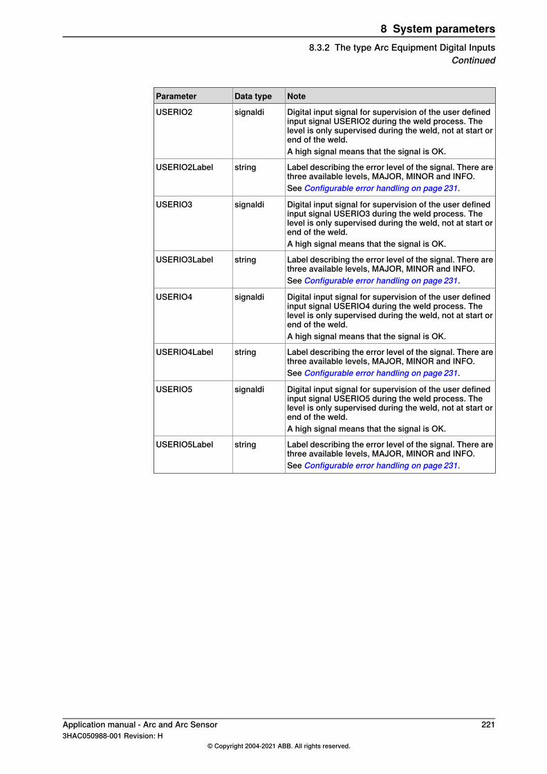
NoteData typeParameter
Digital input signal for supervision of the user definedinput signal USERIO2 during the weld process. Thelevel is only supervised during the weld, not at start orend of the weld.
signaldiUSERIO2
A high signal means that the signal is OK.
Label describing the error level of the signal. There arethree available levels, MAJOR, MINOR and INFO.
stringUSERIO2Label
See Configurable error handling on page 231.
Digital input signal for supervision of the user definedinput signal USERIO3 during the weld process. Thelevel is only supervised during the weld, not at start orend of the weld.
signaldiUSERIO3
A high signal means that the signal is OK.
Label describing the error level of the signal. There arethree available levels, MAJOR, MINOR and INFO.
stringUSERIO3Label
See Configurable error handling on page 231.
Digital input signal for supervision of the user definedinput signal USERIO4 during the weld process. Thelevel is only supervised during the weld, not at start orend of the weld.
signaldiUSERIO4
A high signal means that the signal is OK.
Label describing the error level of the signal. There arethree available levels, MAJOR, MINOR and INFO.
stringUSERIO4Label
See Configurable error handling on page 231.
Digital input signal for supervision of the user definedinput signal USERIO5 during the weld process. Thelevel is only supervised during the weld, not at start orend of the weld.
signaldiUSERIO5
A high signal means that the signal is OK.
Label describing the error level of the signal. There arethree available levels, MAJOR, MINOR and INFO.
stringUSERIO5Label
See Configurable error handling on page 231.
Application manual - Arc and Arc Sensor 2213HAC050988-001 Revision: H
© Copyright 2004-2021 ABB. All rights reserved.
8 System parameters8.3.2 The type Arc Equipment Digital Inputs
Continued
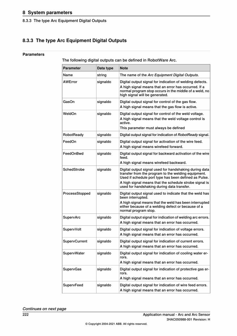
8.3.3 The type Arc Equipment Digital Outputs
ParametersThe following digital outputs can be defined in RobotWare Arc.
NoteData typeParameter
The name of the Arc Equipment Digital Outputs.stringName
Digital output signal for indication of welding defects.signaldoAWErrorA high signal means that an error has occurred. If anormal program stop occurs in the middle of a weld, nohigh signal will be generated.
Digital output signal for control of the gas flow.signaldoGasOnA high signal means that the gas flow is active.
Digital output signal for control of the weld voltage.signaldoWeldOnA high signal means that the weld voltage control isactive.This parameter must always be defined
Digital output signal for indication ofRobotReady signal.signaldoRobotReady
Digital output signal for activation of the wire feed.signaldoFeedOnA high signal means wirefeed forward.
Digital output signal for backward activation of the wirefeed.
signaldoFeedOnBwd
A high signal means wirefeed backward.
Digital output signal used for handshaking during datatransfer from the program to the welding equipment.Used if schedule port type has been defined as Pulse.
signaldoSchedStrobe
A high signal means that the schedule strobe signal isused for handshaking during data transfer.
Digital output signal used to indicate that the weld hasbeen interrupted.
signaldoProcessStopped
A high signal means that the weld has been interruptedeither because of a welding defect or because of anormal program stop.
Digital output signal for indication of welding arc errors.signaldoSupervArcA high signal means that an error has occurred.
Digital output signal for indication of voltage errors.signaldoSupervVoltA high signal means that an error has occurred.
Digital output signal for indication of current errors.signaldoSupervCurrentA high signal means that an error has occurred.
Digital output signal for indication of cooling water er-rors.
signaldoSupervWater
A high signal means that an error has occurred.
Digital output signal for indication of protective gas er-rors.
signaldoSupervGas
A high signal means that an error has occurred.
Digital output signal for indication of wire feed errors.signaldoSupervFeedA high signal means that an error has occurred.
Continues on next page222 Application manual - Arc and Arc Sensor
3HAC050988-001 Revision: H© Copyright 2004-2021 ABB. All rights reserved.
8 System parameters8.3.3 The type Arc Equipment Digital Outputs

NoteData typeParameter
Digital output signal for indication of torch errors.signaldoSupervGunA high signal means that an error has occurred.
Digital output signal for indication of Blocked processsignaldoAWBlock
Digital output signal for indication of WelderReady signalerrors. A high signal means that an error has occurred.
signaldoSupervWelder-Ready
Application manual - Arc and Arc Sensor 2233HAC050988-001 Revision: H
© Copyright 2004-2021 ABB. All rights reserved.
8 System parameters8.3.3 The type Arc Equipment Digital Outputs
Continued
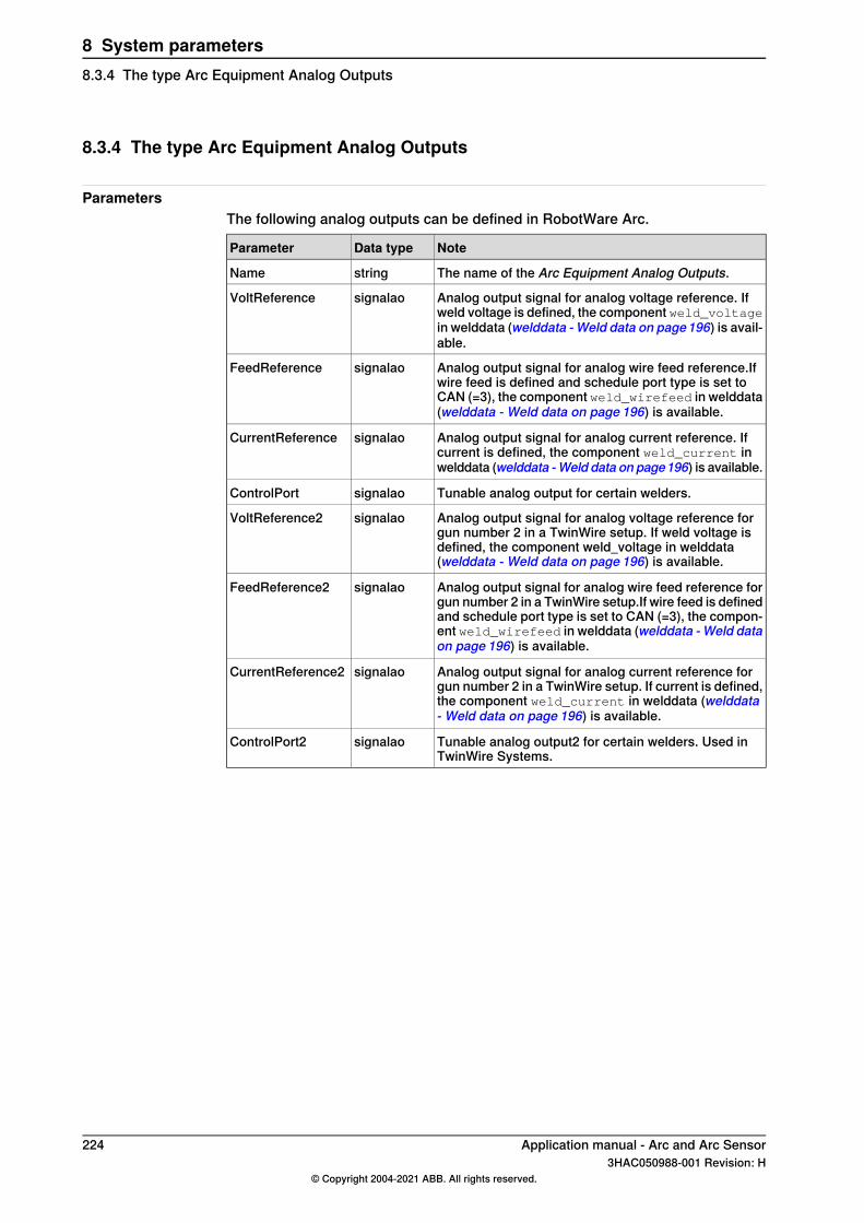
8.3.4 The type Arc Equipment Analog Outputs
ParametersThe following analog outputs can be defined in RobotWare Arc.
NoteData typeParameter
The name of the Arc Equipment Analog Outputs.stringName
Analog output signal for analog voltage reference. Ifweld voltage is defined, the component weld_voltagein welddata (welddata - Weld data on page196) is avail-able.
signalaoVoltReference
Analog output signal for analog wire feed reference.Ifwire feed is defined and schedule port type is set toCAN (=3), the component weld_wirefeed in welddata(welddata - Weld data on page 196) is available.
signalaoFeedReference
Analog output signal for analog current reference. Ifcurrent is defined, the component weld_current inwelddata (welddata -Weld data on page196) is available.
signalaoCurrentReference
Tunable analog output for certain welders.signalaoControlPort
Analog output signal for analog voltage reference forgun number 2 in a TwinWire setup. If weld voltage isdefined, the component weld_voltage in welddata(welddata - Weld data on page 196) is available.
signalaoVoltReference2
Analog output signal for analog wire feed reference forgun number 2 in a TwinWire setup.If wire feed is definedand schedule port type is set to CAN (=3), the compon-ent weld_wirefeed in welddata (welddata - Weld dataon page 196) is available.
signalaoFeedReference2
Analog output signal for analog current reference forgun number 2 in a TwinWire setup. If current is defined,the component weld_current in welddata (welddata- Weld data on page 196) is available.
signalaoCurrentReference2
Tunable analog output2 for certain welders. Used inTwinWire Systems.
signalaoControlPort2
224 Application manual - Arc and Arc Sensor3HAC050988-001 Revision: H
© Copyright 2004-2021 ABB. All rights reserved.
8 System parameters8.3.4 The type Arc Equipment Analog Outputs
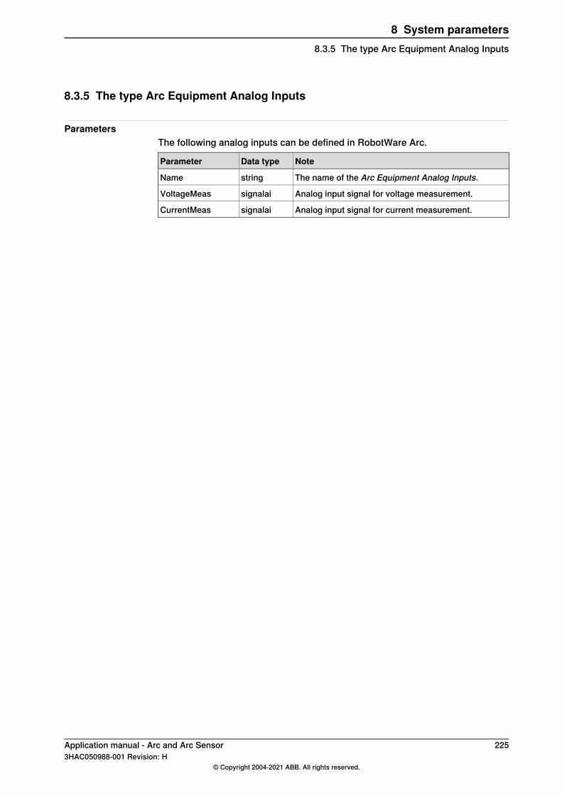
8.3.5 The type Arc Equipment Analog Inputs
ParametersThe following analog inputs can be defined in RobotWare Arc.
NoteData typeParameter
The name of the Arc Equipment Analog Inputs.stringName
Analog input signal for voltage measurement.signalaiVoltageMeas
Analog input signal for current measurement.signalaiCurrentMeas
Application manual - Arc and Arc Sensor 2253HAC050988-001 Revision: H
© Copyright 2004-2021 ABB. All rights reserved.
8 System parameters8.3.5 The type Arc Equipment Analog Inputs
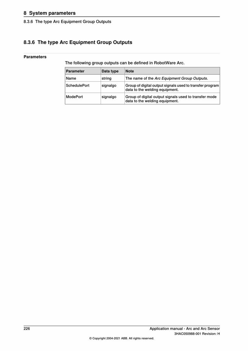
8.3.6 The type Arc Equipment Group Outputs
ParametersThe following group outputs can be defined in RobotWare Arc.
NoteData typeParameter
The name of the Arc Equipment Group Outputs.stringName
Group of digital output signals used to transfer programdata to the welding equipment.
signalgoSchedulePort
Group of digital output signals used to transfer modedata to the welding equipment.
signalgoModePort
226 Application manual - Arc and Arc Sensor3HAC050988-001 Revision: H
© Copyright 2004-2021 ABB. All rights reserved.
8 System parameters8.3.6 The type Arc Equipment Group Outputs
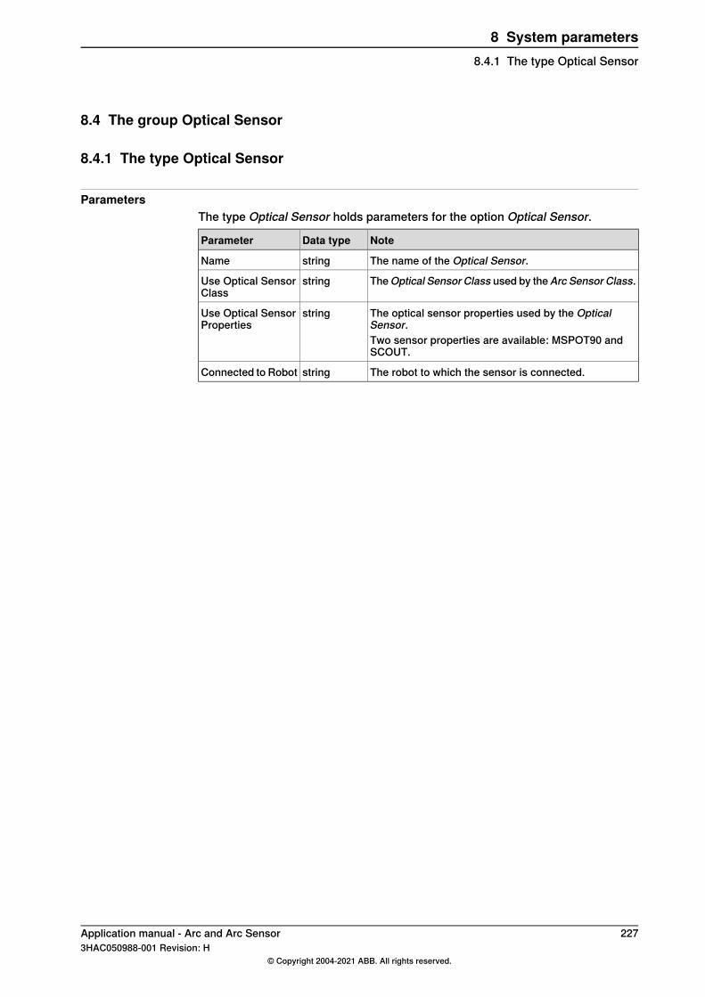
8.4 The group Optical Sensor
8.4.1 The type Optical Sensor
ParametersThe type Optical Sensor holds parameters for the option Optical Sensor.
NoteData typeParameter
The name of the Optical Sensor.stringName
TheOptical Sensor Class used by theArc Sensor Class.stringUse Optical SensorClass
The optical sensor properties used by the OpticalSensor.
stringUse Optical SensorProperties
Two sensor properties are available: MSPOT90 andSCOUT.
The robot to which the sensor is connected.stringConnected to Robot
Application manual - Arc and Arc Sensor 2273HAC050988-001 Revision: H
© Copyright 2004-2021 ABB. All rights reserved.
8 System parameters8.4.1 The type Optical Sensor
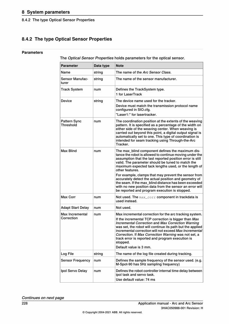
8.4.2 The type Optical Sensor Properties
ParametersThe Optical Sensor Properties holds parameters for the optical sensor.
NoteData typeParameter
The name of the Arc Sensor Class.stringName
The name of the sensor manufacturer.stringSensor Manufac-turer
Defines the TrackSystem type.numTrack System1 for LaserTrack
The device name used for the tracker.stringDeviceDevice must match the transmission protocol nameconfigured in SIO.cfg."Laser1:" for lasertracker.
The coordination position at the extents of the weavingpattern. It is specified as a percentage of the width oneither side of the weaving center. When weaving iscarried out beyond this point, a digital output signal isautomatically set to one. This type of coordination isintended for seam tracking using Through-the-ArcTracker.
numPattern SyncThreshold
The max_blind component defines the maximum dis-tance the robot is allowed to continue moving under theassumption that the last reported position error is stillvalid. The parameter should be tuned to match themaximum expected tack lengths used, or the length ofother features.
numMax Blind
For example, clamps that may prevent the sensor fromaccurately detect the actual position and geometry ofthe seam. If the max_blind distance has been exceededwith no new position data from the sensor an error willbe reported and program execution is stopped.
Not used. The max_corr component in trackdata isused instead.
numMax Corr
Not used.numAdapt Start Delay
Max incremental correction for the arc tracking system.numMax IncrementalCorrection If the incremental TCP correction is bigger than Max
Incremental Correction and Max Correction Warningwas set, the robot will continue its path but the appliedincremental correction will not exceedMax IncrementalCorrection. If Max Correction Warning was not set, atrack error is reported and program execution isstopped.Default value is 3 mm.
The name of the log file created during tracking.stringLog File
Defines the sample frequency of the sensor used. (e.g.M-Spot-90 has 5Hz sampling frequency)
numSensor Frequency
Defines the robot controller internal time delay betweenipol task and servo task.
numIpol Servo Delay
Use default value: 74 ms
Continues on next page228 Application manual - Arc and Arc Sensor
3HAC050988-001 Revision: H© Copyright 2004-2021 ABB. All rights reserved.
8 System parameters8.4.2 The type Optical Sensor Properties
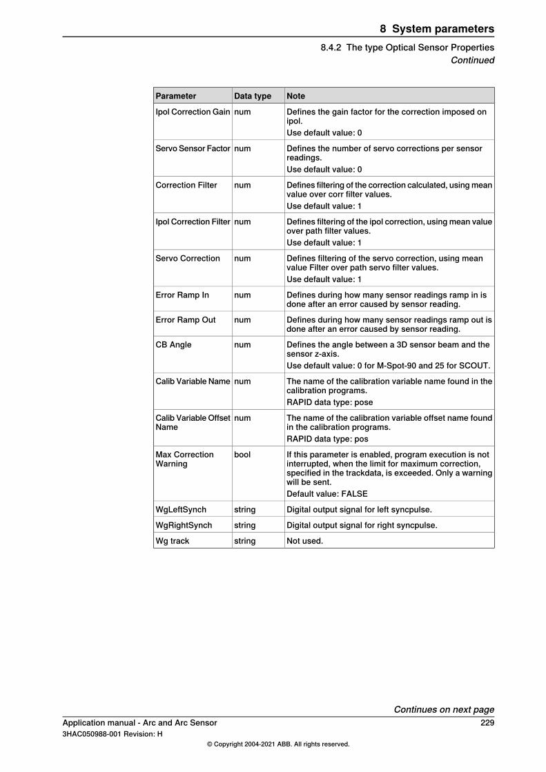
NoteData typeParameter
Defines the gain factor for the correction imposed onipol.
numIpol Correction Gain
Use default value: 0
Defines the number of servo corrections per sensorreadings.
numServo Sensor Factor
Use default value: 0
Defines filtering of the correction calculated, using meanvalue over corr filter values.
numCorrection Filter
Use default value: 1
Defines filtering of the ipol correction, using mean valueover path filter values.
numIpol Correction Filter
Use default value: 1
Defines filtering of the servo correction, using meanvalue Filter over path servo filter values.
numServo Correction
Use default value: 1
Defines during how many sensor readings ramp in isdone after an error caused by sensor reading.
numError Ramp In
Defines during how many sensor readings ramp out isdone after an error caused by sensor reading.
numError Ramp Out
Defines the angle between a 3D sensor beam and thesensor z-axis.
numCB Angle
Use default value: 0 for M-Spot-90 and 25 for SCOUT.
The name of the calibration variable name found in thecalibration programs.
numCalib Variable Name
RAPID data type: pose
The name of the calibration variable offset name foundin the calibration programs.
numCalib Variable OffsetName
RAPID data type: pos
If this parameter is enabled, program execution is notinterrupted, when the limit for maximum correction,specified in the trackdata, is exceeded. Only a warningwill be sent.
boolMax CorrectionWarning
Default value: FALSE
Digital output signal for left syncpulse.stringWgLeftSynch
Digital output signal for right syncpulse.stringWgRightSynch
Not used.stringWg track
Continues on next pageApplication manual - Arc and Arc Sensor 2293HAC050988-001 Revision: H
© Copyright 2004-2021 ABB. All rights reserved.
8 System parameters8.4.2 The type Optical Sensor Properties
Continued
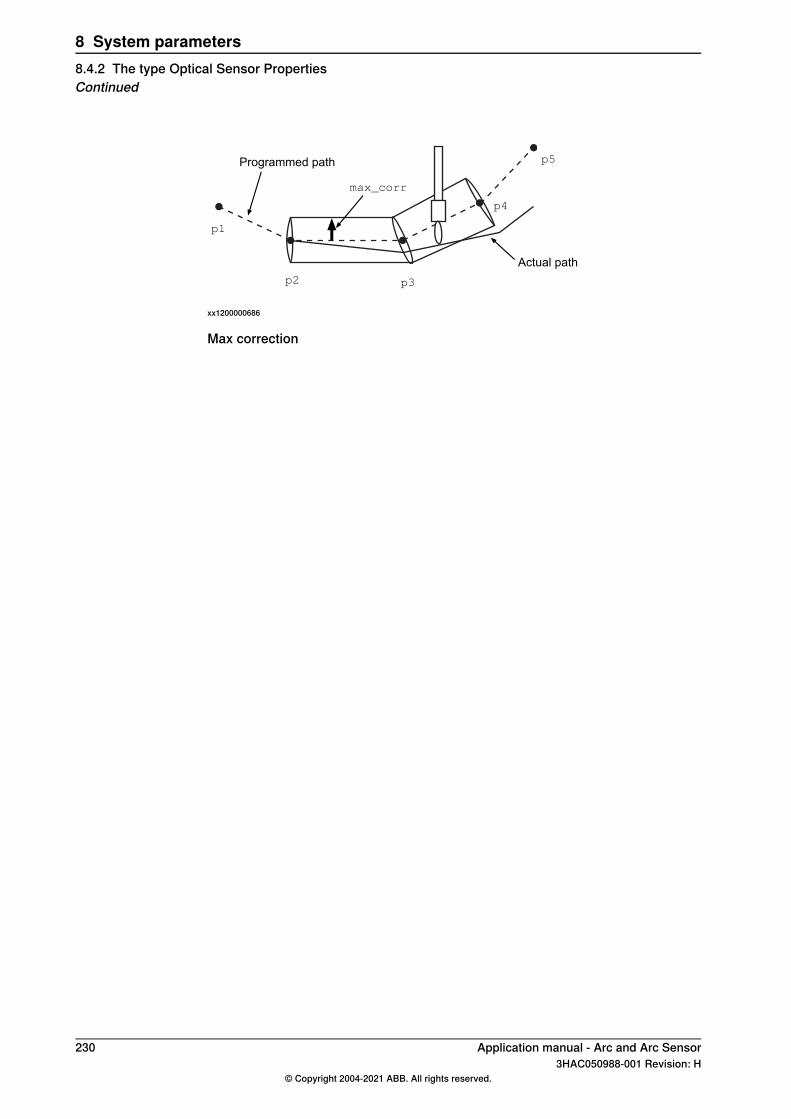
Programmed path
Actual path
max_corr
p1
p2 p3
p4
p5
xx1200000686
Max correction
230 Application manual - Arc and Arc Sensor3HAC050988-001 Revision: H
© Copyright 2004-2021 ABB. All rights reserved.
8 System parameters8.4.2 The type Optical Sensor PropertiesContinued
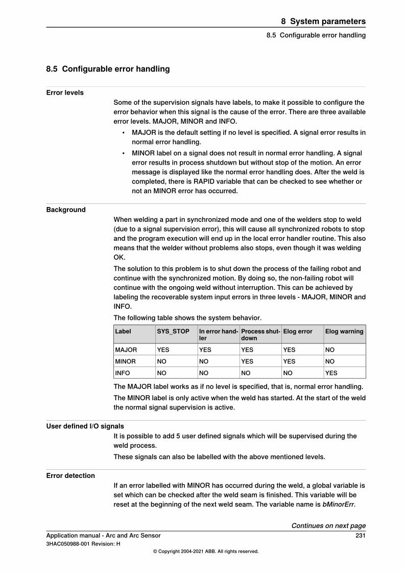
8.5 Configurable error handling
Error levelsSome of the supervision signals have labels, to make it possible to configure theerror behavior when this signal is the cause of the error. There are three availableerror levels. MAJOR, MINOR and INFO.
• MAJOR is the default setting if no level is specified. A signal error results innormal error handling.
• MINOR label on a signal does not result in normal error handling. A signalerror results in process shutdown but without stop of the motion. An errormessage is displayed like the normal error handling does. After the weld iscompleted, there is RAPID variable that can be checked to see whether ornot an MINOR error has occurred.
BackgroundWhen welding a part in synchronized mode and one of the welders stop to weld(due to a signal supervision error), this will cause all synchronized robots to stopand the program execution will end up in the local error handler routine. This alsomeans that the welder without problems also stops, even though it was weldingOK.The solution to this problem is to shut down the process of the failing robot andcontinue with the synchronized motion. By doing so, the non-failing robot willcontinue with the ongoing weld without interruption. This can be achieved bylabeling the recoverable system input errors in three levels - MAJOR, MINOR andINFO.The following table shows the system behavior.
Elog warningElog errorProcess shut-down
In error hand-ler
SYS_STOPLabel
NOYESYESYESYESMAJOR
NOYESYESNONOMINOR
YESNONONONOINFO
The MAJOR label works as if no level is specified, that is, normal error handling.The MINOR label is only active when the weld has started. At the start of the weldthe normal signal supervision is active.
User defined I/O signalsIt is possible to add 5 user defined signals which will be supervised during theweld process.These signals can also be labelled with the above mentioned levels.
Error detectionIf an error labelled with MINOR has occurred during the weld, a global variable isset which can be checked after the weld seam is finished. This variable will bereset at the beginning of the next weld seam. The variable name is bMinorErr.
Continues on next pageApplication manual - Arc and Arc Sensor 2313HAC050988-001 Revision: H
© Copyright 2004-2021 ABB. All rights reserved.
8 System parameters8.5 Configurable error handling
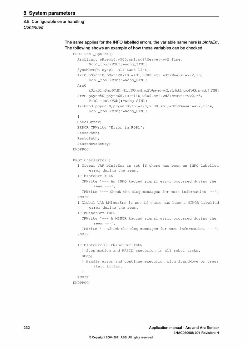
The same applies for the INFO labelled errors, the variable name here is bInfoErr.The following shows an example of how these variables can be checked.
PROC Rob1_UpSide()
ArcLStart pPrep10,v500,sm1,wd2\Weave:=wv2,fine,Rob1_tool\WObj:=wobj_STN1;
SyncMoveOn sync1, all_task_list;
ArcC pSync10,pSync20\ID:=id1,v300,sm1,wd2\Weave:=wv2,z5,Rob1_tool\WObj:=wobj_STN1;
ArcCpSync30,pSync40\ID:=11,v300,sm1,wd2\Weave:=wv2,z5,Rob1_tool\WObj:=wobj_STN1;
ArcC pSync50,pSync60\ID:=110,v300,sm1,wd2\Weave:=wv2,z5,Rob1_tool\WObj:=wobj_STN1;
ArcCEnd pSync70,pSync80\ID:=120,v300,sm1,wd2\Weave:=wv2,fine,Rob1_tool\WObj:=wobj_STN1;
!
CheckError;
ERROR TPWrite "Error in ROB1";
StorePath;
RestoPath;
StartMoveRetry;
ENDPROC
PROC CheckError()
! Global VAR bInfoErr is set if there has been an INFO labellederror during the seam.
IF bInfoErr THEN
TPWrite "--- An INFO tagged signal error occurred during theseam ---";
TPWrite "--- Check the elog messages for more information. --";
ENDIF
! Global VAR bMinorErr is set if there has been a MINOR labellederror during the seam.
IF bMinorErr THEN
TPWrite "--- A MINOR tagged signal error occurred during theseam ---";
TPWrite "---Check the elog messages for more information. ---";
ENDIF
IF bInfoErr OR bMinorErr THEN
! Stop motion and RAPID execution in all robot tasks.
Stop;
! Handle error and continue execution with StartMove or pressstart button.
!
ENDIF
ENDPROC
232 Application manual - Arc and Arc Sensor3HAC050988-001 Revision: H
© Copyright 2004-2021 ABB. All rights reserved.
8 System parameters8.5 Configurable error handlingContinued
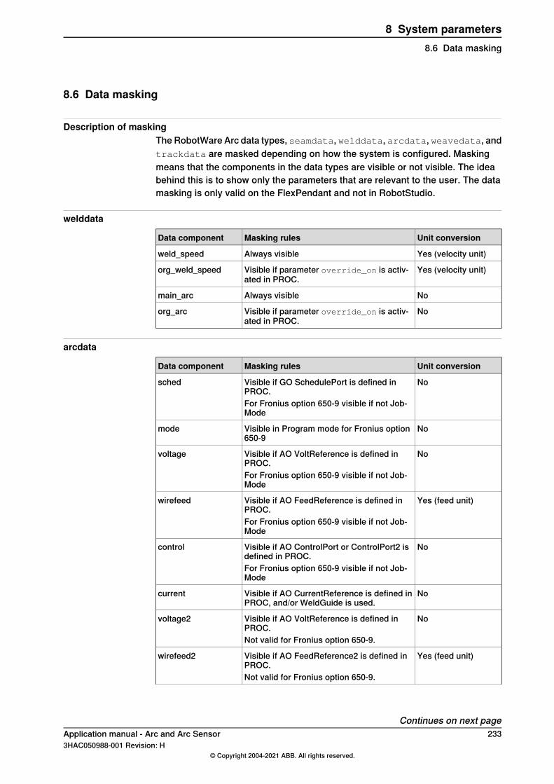
8.6 Data masking
Description of maskingThe RobotWare Arc data types, seamdata, welddata, arcdata, weavedata, andtrackdata are masked depending on how the system is configured. Maskingmeans that the components in the data types are visible or not visible. The ideabehind this is to show only the parameters that are relevant to the user. The datamasking is only valid on the FlexPendant and not in RobotStudio.
welddata
Unit conversionMasking rulesData component
Yes (velocity unit)Always visibleweld_speed
Yes (velocity unit)Visible if parameter override_on is activ-ated in PROC.
org_weld_speed
NoAlways visiblemain_arc
NoVisible if parameter override_on is activ-ated in PROC.
org_arc
arcdata
Unit conversionMasking rulesData component
NoVisible if GO SchedulePort is defined inPROC.
sched
For Fronius option 650-9 visible if not Job-Mode
NoVisible in Program mode for Fronius option650-9
mode
NoVisible if AO VoltReference is defined inPROC.
voltage
For Fronius option 650-9 visible if not Job-Mode
Yes (feed unit)Visible if AO FeedReference is defined inPROC.
wirefeed
For Fronius option 650-9 visible if not Job-Mode
NoVisible if AO ControlPort or ControlPort2 isdefined in PROC.
control
For Fronius option 650-9 visible if not Job-Mode
NoVisible if AO CurrentReference is defined inPROC, and/or WeldGuide is used.
current
NoVisible if AO VoltReference is defined inPROC.
voltage2
Not valid for Fronius option 650-9.
Yes (feed unit)Visible if AO FeedReference2 is defined inPROC.
wirefeed2
Not valid for Fronius option 650-9.
Continues on next pageApplication manual - Arc and Arc Sensor 2333HAC050988-001 Revision: H
© Copyright 2004-2021 ABB. All rights reserved.
8 System parameters8.6 Data masking
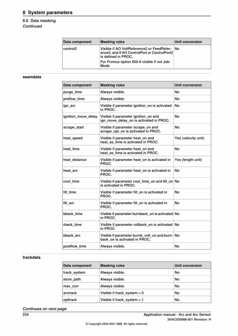
Unit conversionMasking rulesData component
NoVisible if AO VoltReference2 or FeedRefer-ence2, and if AO ControlPort or ControlPort2is defined in PROC.
control2
For Fronius option 650-9 visible if not Job-Mode
seamdata
Unit conversionMasking rulesData component
NoAlways visible.purge_time
NoAlways visible.preflow_time
NoVisible if parameter ignition_on is activatedin PROC.
ign_arc
NoVisible if parameter ignition_on andign_move_delay_on is activated in PROC.
ignition_move_delay
NoVisible if parameter scrape_on andscrape_opt_on is activated in PROC.
scrape_start
Yes (velocity unit)Visible if parameter heat_on andheat_as_time is activated in PROC.
heat_speed
NoVisible if parameter heat_on andheat_as_time is activated in PROC.
heat_time
Yes (length unit)Visible if parameter heat_on is activated inPROC.
heat_distance
NoVisible if parameter heat_on is activated inPROC.
heat_arc
NoVisible if parameter cool_time_on and fill_onis activated in PROC.
cool_time
NoVisible if parameter fill_on is activated inPROC.
fill_time
NoVisible if parameter fill_on is activated inPROC.
fill_arc
NoVisible if parameter burnback_on is activatedin PROC.
bback_time
NoVisible if parameter rollback_on is activatedin PROC.
rback_time
NoVisible if parameter burnb_volt_on and burn-back_on is activated in PROC.
bback_arc
NoAlways visible.postflow_time
trackdata
Unit conversionMasking rulesData component
NoAlways visible.track_system
NoAlways visible.store_path
NoAlways visible.max_corr
NoVisible if track_system = 0arctrack
NoVisible if track_system = 1opttrack
Continues on next page234 Application manual - Arc and Arc Sensor
3HAC050988-001 Revision: H© Copyright 2004-2021 ABB. All rights reserved.
8 System parameters8.6 Data maskingContinued
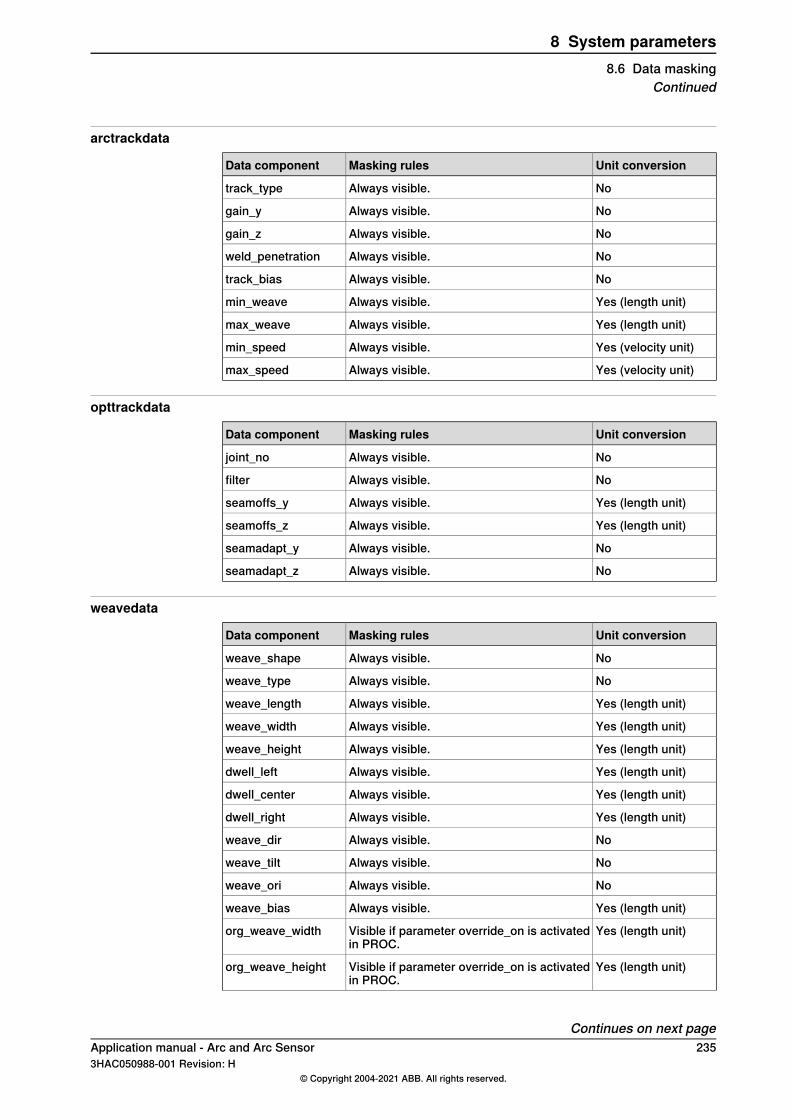
arctrackdata
Unit conversionMasking rulesData component
NoAlways visible.track_type
NoAlways visible.gain_y
NoAlways visible.gain_z
NoAlways visible.weld_penetration
NoAlways visible.track_bias
Yes (length unit)Always visible.min_weave
Yes (length unit)Always visible.max_weave
Yes (velocity unit)Always visible.min_speed
Yes (velocity unit)Always visible.max_speed
opttrackdata
Unit conversionMasking rulesData component
NoAlways visible.joint_no
NoAlways visible.filter
Yes (length unit)Always visible.seamoffs_y
Yes (length unit)Always visible.seamoffs_z
NoAlways visible.seamadapt_y
NoAlways visible.seamadapt_z
weavedata
Unit conversionMasking rulesData component
NoAlways visible.weave_shape
NoAlways visible.weave_type
Yes (length unit)Always visible.weave_length
Yes (length unit)Always visible.weave_width
Yes (length unit)Always visible.weave_height
Yes (length unit)Always visible.dwell_left
Yes (length unit)Always visible.dwell_center
Yes (length unit)Always visible.dwell_right
NoAlways visible.weave_dir
NoAlways visible.weave_tilt
NoAlways visible.weave_ori
Yes (length unit)Always visible.weave_bias
Yes (length unit)Visible if parameter override_on is activatedin PROC.
org_weave_width
Yes (length unit)Visible if parameter override_on is activatedin PROC.
org_weave_height
Continues on next pageApplication manual - Arc and Arc Sensor 2353HAC050988-001 Revision: H
© Copyright 2004-2021 ABB. All rights reserved.
8 System parameters8.6 Data masking
Continued

Unit conversionMasking rulesData component
Yes (length unit)Visible if parameter override_on is activatedin PROC.
org_weave_bias
236 Application manual - Arc and Arc Sensor3HAC050988-001 Revision: H
© Copyright 2004-2021 ABB. All rights reserved.
8 System parameters8.6 Data maskingContinued
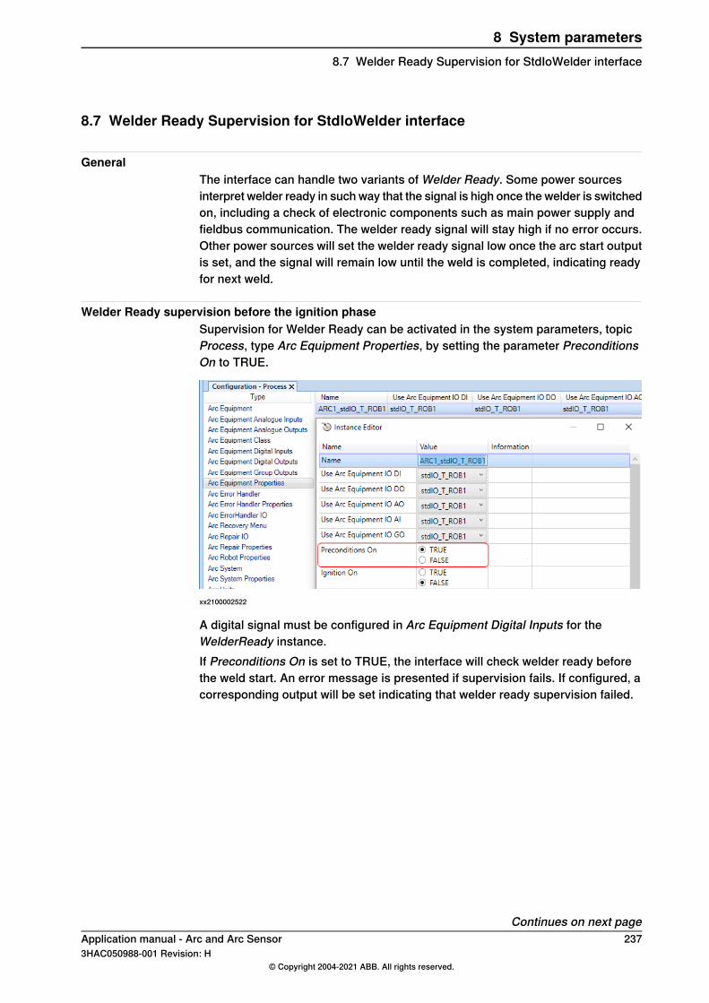
8.7 Welder Ready Supervision for StdIoWelder interface
GeneralThe interface can handle two variants of Welder Ready. Some power sourcesinterpret welder ready in such way that the signal is high once the welder is switchedon, including a check of electronic components such as main power supply andfieldbus communication. The welder ready signal will stay high if no error occurs.Other power sources will set the welder ready signal low once the arc start outputis set, and the signal will remain low until the weld is completed, indicating readyfor next weld.
Welder Ready supervision before the ignition phaseSupervision for Welder Ready can be activated in the system parameters, topicProcess, type Arc Equipment Properties, by setting the parameter PreconditionsOn to TRUE.
xx2100002522
A digital signal must be configured in Arc Equipment Digital Inputs for theWelderReady instance.If Preconditions On is set to TRUE, the interface will check welder ready beforethe weld start. An error message is presented if supervision fails. If configured, acorresponding output will be set indicating that welder ready supervision failed.
Continues on next pageApplication manual - Arc and Arc Sensor 2373HAC050988-001 Revision: H
© Copyright 2004-2021 ABB. All rights reserved.
8 System parameters8.7 Welder Ready Supervision for StdIoWelder interface
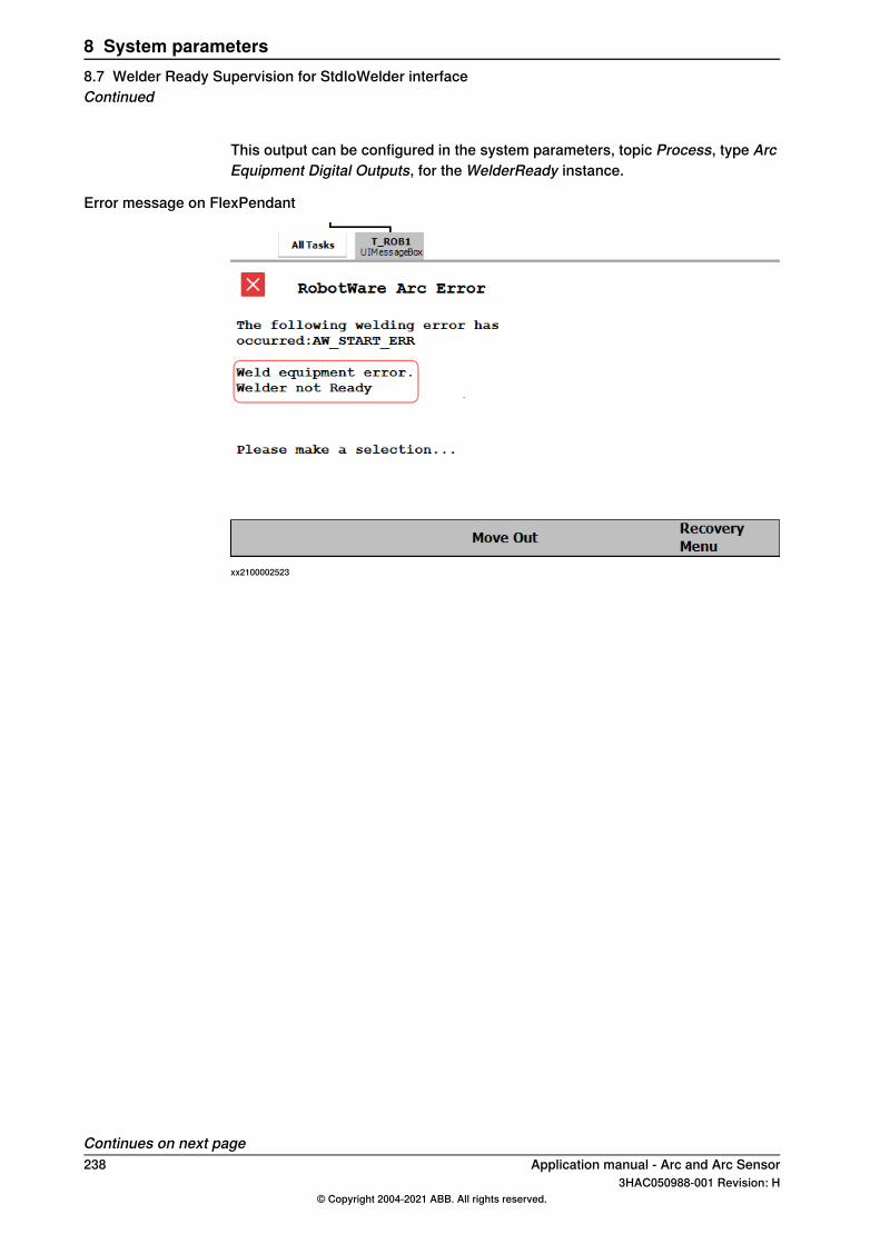
This output can be configured in the system parameters, topic Process, type ArcEquipment Digital Outputs, for the WelderReady instance.
Error message on FlexPendant
xx2100002523
Continues on next page238 Application manual - Arc and Arc Sensor
3HAC050988-001 Revision: H© Copyright 2004-2021 ABB. All rights reserved.
8 System parameters8.7 Welder Ready Supervision for StdIoWelder interfaceContinued
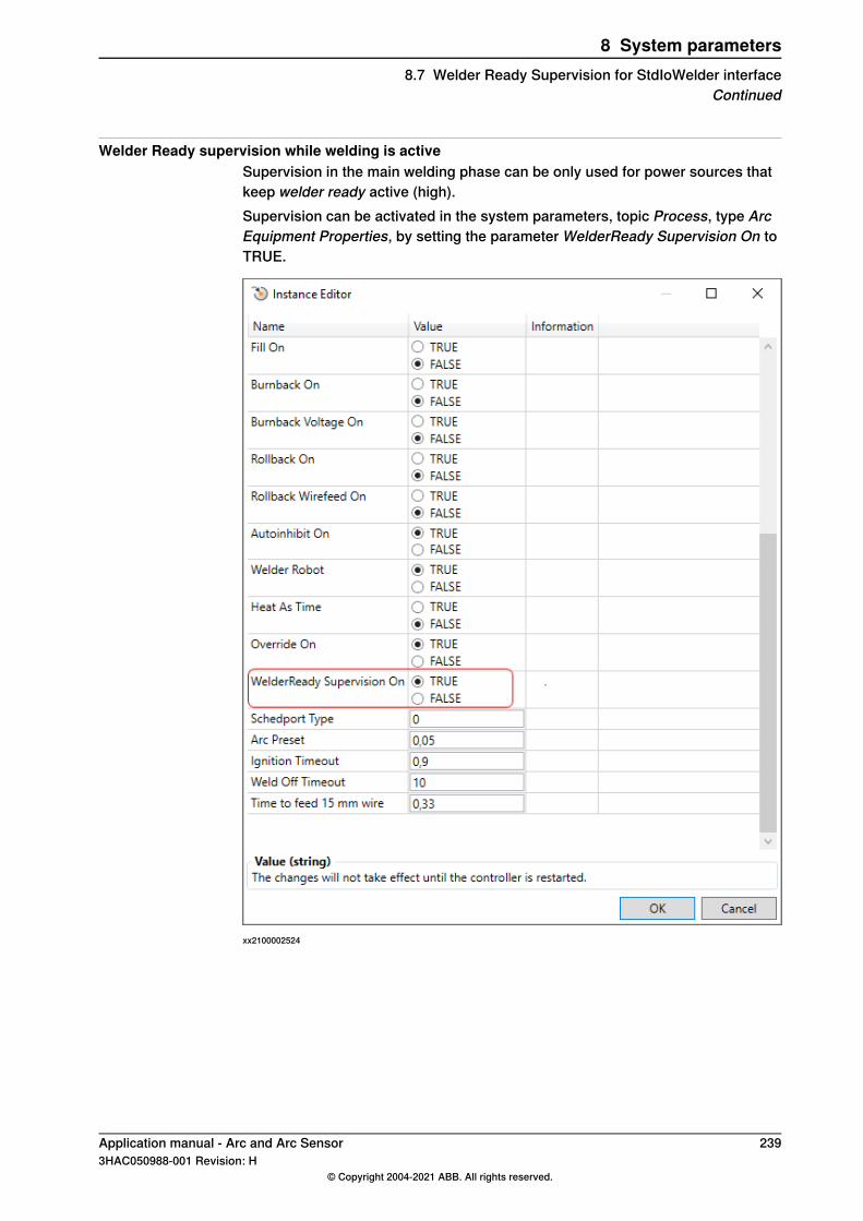
Welder Ready supervision while welding is activeSupervision in the main welding phase can be only used for power sources thatkeep welder ready active (high).Supervision can be activated in the system parameters, topic Process, type ArcEquipment Properties, by setting the parameter WelderReady Supervision On toTRUE.
xx2100002524
Application manual - Arc and Arc Sensor 2393HAC050988-001 Revision: H
© Copyright 2004-2021 ABB. All rights reserved.
8 System parameters8.7 Welder Ready Supervision for StdIoWelder interface
Continued

This page is intentionally left blank
IndexAAdaptive Process Control, 11Additional Arc Systems, 10advSeamData, 171ArcC, 107ArcCEnd, 115ArcCStart, 123arcdata, 174Arc Equipment, 213Arc Equipment Class, 214ArcL, 132ArcLEnd, 140ArcLStart, 148ArcMoveExtJ, 157ArcRefresh, 159Arc Robot Properties, 208Arc System Properties, 204Arc System settings, 203Arc Units, 212arc welding data, 21arc welding instructions, 21AristoMig, 9auto mode functions, 26
Bblocking, 29
CCorrClear, 13CorrCon, 13corrdescr, 13CorrDiscon, 13CorrRead, 13CorrWrite, 13
Ddata masking, 233data tuning, 32data types
advSeamData, 171arcdata, 174flystartdata, 176seamdata, 177trackdata, 183weavedata, 189welddata, 196
Eerror levels, 231ESAB AristoMig, 9
Fflystartdata, 176Fronius, 9
Ggas purge, 31Generic Equipment Class, 201, 215
Iincrements, 31installation options, 9instructions
ArcC, 107ArcCEnd, 115
ArcCStart, 123ArcL, 132ArcLEnd, 140ArcLStart, 148ArcMoveExtJ, 157ArcRefresh, 159RecoveryMenu, 161RecoveryMenuWR, 163RecoveryPosReset, 168RecoveryPosSet, 165SetWRProcName, 170
IVarValue, 14
LLaser Tracker systems, 12limitations
MultiMove, 46Weld Repair, 81
Lincoln ArcLink, 9
Mmanual gas purge, 31manual mode functions, 26manual wirefeed, 30MultiMove
description, 35programming, 42
OOptical Sensor, 227optical tracking, 15Optical Tracking Arc, 10Optical tracking Arc [660-1], 11
Ppath correction instructions, 13Path offset, 13program controlled tuning, 11, 19programming, 23
MultiMove, 42Weld Error Recovery, 51
RReadBlock, 14ReadVar, 14RecoveryMenu, 161RecoveryMenuWR, 163RecoveryPosReset, 168RecoveryPosSet, 165
Sseamdata, 177seam tracking, 11, 13sensor controlled tuning, 11, 18Sensor Interface, 14SetWRProcName, 170Simulated Welder, 9SKS SynchroWeld, 9Standard I/O Welder, 9
TTrack
argument, 15trackdata, 183tuning
data, 32increments, 31
Application manual - Arc and Arc Sensor 2413HAC050988-001 Revision: H
© Copyright 2004-2021 ABB. All rights reserved.
Index

program controlled, 19sensor controlled, 18weave data, 28weld data, 27
Uunit settings, 205
Wweavedata, 189welddata, 196weld error handling, 49
Weld Error Recoverydescription, 49programming, 51
weld errors, 49WeldGuide [815-1], 11WeldGuide Tracker systems, 12, 16Weld Repair
configuring, 83description, 81
wirefeed, 30WriteBlock, 14
242 Application manual - Arc and Arc Sensor3HAC050988-001 Revision: H
© Copyright 2004-2021 ABB. All rights reserved.
Index

ABB ABRobotics & Discrete AutomationS-721 68 VÄSTERÅS, SwedenTelephone +46 (0) 21 344 400
ABB ASRobotics & Discrete AutomationNordlysvegen 7, N-4340 BRYNE, NorwayBox 265, N-4349 BRYNE, NorwayTelephone: +47 22 87 2000
ABB Engineering (Shanghai) Ltd.Robotics & Discrete AutomationNo. 4528 Kangxin HighwayPuDong DistrictSHANGHAI 201319, ChinaTelephone: +86 21 6105 6666
ABB Inc.Robotics & Discrete Automation1250 Brown RoadAuburn Hills, MI 48326USATelephone: +1 248 391 9000
abb.com/robotics
3HAC050988-001,Rev
H,en
© Copyright 2004-2021 ABB. All rights reserved.Specifications subject to change without notice.