Embed Size (px)
Citation preview

© C
opyr
ight
200
8 A
BB
. All
right
s res
erve
d.
Operating manualRobot Studio
5.11
Document ID: 3HAC032104-001
Status: Approved
Revision: A

© C
opyr
ight
200
8 A
BB
. All
right
s res
erve
d.
The information in this manual is subject to change without notice and should not be construed as a commitment by ABB. ABB assumes no responsibility for any errors that may appear in this manual.Except as may be expressly stated anywhere in this manual, nothing herein shall be construed as any kind of guarantee or warranty by ABB for losses, damages to persons or property, fitness for a specific purpose or the like.In no event shall ABB be liable for incidental or consequential damages arising from use of this manual and products described herein.This manual and parts thereof must not be reproduced or copied without ABB's written permission, and contents thereof must not be imparted to a third party nor be used for any unauthorized purpose. Contravention will be prosecuted. Additional copies of this manual may be obtained from ABB at its then current charge.
Copyright 2008 ABB All rights reserved.
ABB ABRobotics Products721 68 Västerås
Sweden

Table of Contents
33HAC032104-001 Revision: A Status: Approved
© C
opyr
ight
200
8 A
BB
. All
right
s res
erve
d.
Overview . . . . . . . . . . . . . . . . . . . . . . . . . . . . . . . . . . . . . . . . . . . . . . . . . . . . . . . . . . . . . . . . . . . . . . . . . . . . 10Product documentation, M2004 . . . . . . . . . . . . . . . . . . . . . . . . . . . . . . . . . . . . . . . . . . . . . . . . . . . . . . . . . . . 12Safety . . . . . . . . . . . . . . . . . . . . . . . . . . . . . . . . . . . . . . . . . . . . . . . . . . . . . . . . . . . . . . . . . . . . . . . . . . . . . . . 14
1 Introduction 15
1.1 Terms and Concepts. . . . . . . . . . . . . . . . . . . . . . . . . . . . . . . . . . . . . . . . . . . . . . . . . . . . . . . . . . . . . . . . 151.1.1 Hardware concepts . . . . . . . . . . . . . . . . . . . . . . . . . . . . . . . . . . . . . . . . . . . . . . . . . . . . . . . . . . . . . 151.1.2 RobotWare concepts. . . . . . . . . . . . . . . . . . . . . . . . . . . . . . . . . . . . . . . . . . . . . . . . . . . . . . . . . . . . 171.1.3 RAPID concepts . . . . . . . . . . . . . . . . . . . . . . . . . . . . . . . . . . . . . . . . . . . . . . . . . . . . . . . . . . . . . . . 191.1.4 Concepts of programing . . . . . . . . . . . . . . . . . . . . . . . . . . . . . . . . . . . . . . . . . . . . . . . . . . . . . . . . . 201.1.5 Targets and paths . . . . . . . . . . . . . . . . . . . . . . . . . . . . . . . . . . . . . . . . . . . . . . . . . . . . . . . . . . . . . . 211.1.6 Coordinate systems. . . . . . . . . . . . . . . . . . . . . . . . . . . . . . . . . . . . . . . . . . . . . . . . . . . . . . . . . . . . . 221.1.7 Robot axis configurations. . . . . . . . . . . . . . . . . . . . . . . . . . . . . . . . . . . . . . . . . . . . . . . . . . . . . . . . 241.1.8 Libraries, geometries and CAD files . . . . . . . . . . . . . . . . . . . . . . . . . . . . . . . . . . . . . . . . . . . . . . . 261.1.9 VSTA as the IDE . . . . . . . . . . . . . . . . . . . . . . . . . . . . . . . . . . . . . . . . . . . . . . . . . . . . . . . . . . . . . . 29
1.2 The Graphical User Interface . . . . . . . . . . . . . . . . . . . . . . . . . . . . . . . . . . . . . . . . . . . . . . . . . . . . . . . . . 301.2.1 The Getting Started window. . . . . . . . . . . . . . . . . . . . . . . . . . . . . . . . . . . . . . . . . . . . . . . . . . . . . . 301.2.2 The Layout browser . . . . . . . . . . . . . . . . . . . . . . . . . . . . . . . . . . . . . . . . . . . . . . . . . . . . . . . . . . . . 311.2.3 The Paths & Targets browser . . . . . . . . . . . . . . . . . . . . . . . . . . . . . . . . . . . . . . . . . . . . . . . . . . . . . 321.2.4 The Modeling browser . . . . . . . . . . . . . . . . . . . . . . . . . . . . . . . . . . . . . . . . . . . . . . . . . . . . . . . . . . 341.2.5 The Offline and Online browsers . . . . . . . . . . . . . . . . . . . . . . . . . . . . . . . . . . . . . . . . . . . . . . . . . . 351.2.6 The Output window . . . . . . . . . . . . . . . . . . . . . . . . . . . . . . . . . . . . . . . . . . . . . . . . . . . . . . . . . . . . 381.2.7 Using a mouse . . . . . . . . . . . . . . . . . . . . . . . . . . . . . . . . . . . . . . . . . . . . . . . . . . . . . . . . . . . . . . . . 411.2.8 Selecting an item . . . . . . . . . . . . . . . . . . . . . . . . . . . . . . . . . . . . . . . . . . . . . . . . . . . . . . . . . . . . . . 421.2.9 Attaching and detaching objects. . . . . . . . . . . . . . . . . . . . . . . . . . . . . . . . . . . . . . . . . . . . . . . . . . . 431.2.10 Keyboard Shortcuts . . . . . . . . . . . . . . . . . . . . . . . . . . . . . . . . . . . . . . . . . . . . . . . . . . . . . . . . . . . 44
2 How to build stations 472.1 Workflow for building a new station . . . . . . . . . . . . . . . . . . . . . . . . . . . . . . . . . . . . . . . . . . . . . . . . . . . . 482.2 The VC . . . . . . . . . . . . . . . . . . . . . . . . . . . . . . . . . . . . . . . . . . . . . . . . . . . . . . . . . . . . . . . . . . . . . . . . . . . 50
2.2.1 Starting a VC . . . . . . . . . . . . . . . . . . . . . . . . . . . . . . . . . . . . . . . . . . . . . . . . . . . . . . . . . . . . . . . . . 502.2.2 Restarting a VC . . . . . . . . . . . . . . . . . . . . . . . . . . . . . . . . . . . . . . . . . . . . . . . . . . . . . . . . . . . . . . . 52
2.3 Station components . . . . . . . . . . . . . . . . . . . . . . . . . . . . . . . . . . . . . . . . . . . . . . . . . . . . . . . . . . . . . . . . 532.3.1 Importing a station component . . . . . . . . . . . . . . . . . . . . . . . . . . . . . . . . . . . . . . . . . . . . . . . . . . . . 532.3.2 Converting CAD formats . . . . . . . . . . . . . . . . . . . . . . . . . . . . . . . . . . . . . . . . . . . . . . . . . . . . . . . . 552.3.3 Troubleshooting and optimizing geometries . . . . . . . . . . . . . . . . . . . . . . . . . . . . . . . . . . . . . . . . . 56
2.4 Modeling . . . . . . . . . . . . . . . . . . . . . . . . . . . . . . . . . . . . . . . . . . . . . . . . . . . . . . . . . . . . . . . . . . . . . . . . . 582.4.1 Objects . . . . . . . . . . . . . . . . . . . . . . . . . . . . . . . . . . . . . . . . . . . . . . . . . . . . . . . . . . . . . . . . . . . . . . 582.4.2 Mechanisms . . . . . . . . . . . . . . . . . . . . . . . . . . . . . . . . . . . . . . . . . . . . . . . . . . . . . . . . . . . . . . . . . . 602.4.3 Tools and tooldata . . . . . . . . . . . . . . . . . . . . . . . . . . . . . . . . . . . . . . . . . . . . . . . . . . . . . . . . . . . . . 612.4.4 Setting the local origin of an object . . . . . . . . . . . . . . . . . . . . . . . . . . . . . . . . . . . . . . . . . . . . . . . . 62
2.5 Placement . . . . . . . . . . . . . . . . . . . . . . . . . . . . . . . . . . . . . . . . . . . . . . . . . . . . . . . . . . . . . . . . . . . . . . . . 632.5.1 Placing objects . . . . . . . . . . . . . . . . . . . . . . . . . . . . . . . . . . . . . . . . . . . . . . . . . . . . . . . . . . . . . . . . 632.5.2 Placing external axes . . . . . . . . . . . . . . . . . . . . . . . . . . . . . . . . . . . . . . . . . . . . . . . . . . . . . . . . . . . 64
3 How to program robots 673.1 Workflow for programing a robot . . . . . . . . . . . . . . . . . . . . . . . . . . . . . . . . . . . . . . . . . . . . . . . . . . . . . . 683.2 Workobjects . . . . . . . . . . . . . . . . . . . . . . . . . . . . . . . . . . . . . . . . . . . . . . . . . . . . . . . . . . . . . . . . . . . . . . . 693.3 Jogging mechanisms. . . . . . . . . . . . . . . . . . . . . . . . . . . . . . . . . . . . . . . . . . . . . . . . . . . . . . . . . . . . . . . . . 703.4 Targets . . . . . . . . . . . . . . . . . . . . . . . . . . . . . . . . . . . . . . . . . . . . . . . . . . . . . . . . . . . . . . . . . . . . . . . . . . . 713.5 Paths . . . . . . . . . . . . . . . . . . . . . . . . . . . . . . . . . . . . . . . . . . . . . . . . . . . . . . . . . . . . . . . . . . . . . . . . . . . . . 733.6 Orientations . . . . . . . . . . . . . . . . . . . . . . . . . . . . . . . . . . . . . . . . . . . . . . . . . . . . . . . . . . . . . . . . . . . . . . . 773.7 RAPID Instructions . . . . . . . . . . . . . . . . . . . . . . . . . . . . . . . . . . . . . . . . . . . . . . . . . . . . . . . . . . . . . . . . . 80

Table of Contents
4 3HAC032104-001 Revision: A Status: Approved
© C
opyr
ight
200
8 A
BB
. All
right
s res
erve
d.
3.8 Testing positions and motions . . . . . . . . . . . . . . . . . . . . . . . . . . . . . . . . . . . . . . . . . . . . . . . . . . . . . . . . . 863.9 Programing MultiMove systems . . . . . . . . . . . . . . . . . . . . . . . . . . . . . . . . . . . . . . . . . . . . . . . . . . . . . . 88
3.9.1 About programing MultiMove. . . . . . . . . . . . . . . . . . . . . . . . . . . . . . . . . . . . . . . . . . . . . . . . . . . . 883.9.2 Setting up the MultiMove . . . . . . . . . . . . . . . . . . . . . . . . . . . . . . . . . . . . . . . . . . . . . . . . . . . . . . . 903.9.3 Testing the MultiMove. . . . . . . . . . . . . . . . . . . . . . . . . . . . . . . . . . . . . . . . . . . . . . . . . . . . . . . . . . 913.9.4 Tuning the motion behavior . . . . . . . . . . . . . . . . . . . . . . . . . . . . . . . . . . . . . . . . . . . . . . . . . . . . . . 923.9.5 Creating paths. . . . . . . . . . . . . . . . . . . . . . . . . . . . . . . . . . . . . . . . . . . . . . . . . . . . . . . . . . . . . . . . . 943.9.6 Programing external axes. . . . . . . . . . . . . . . . . . . . . . . . . . . . . . . . . . . . . . . . . . . . . . . . . . . . . . . . 95
3.10 Loading and saving programs and modules . . . . . . . . . . . . . . . . . . . . . . . . . . . . . . . . . . . . . . . . . . . . . . 973.11 Synchronization . . . . . . . . . . . . . . . . . . . . . . . . . . . . . . . . . . . . . . . . . . . . . . . . . . . . . . . . . . . . . . . . . . . 983.12 Using the RAPID editor . . . . . . . . . . . . . . . . . . . . . . . . . . . . . . . . . . . . . . . . . . . . . . . . . . . . . . . . . . . . . 99
4 How to simulate programs 1034.1 Simulation Overview . . . . . . . . . . . . . . . . . . . . . . . . . . . . . . . . . . . . . . . . . . . . . . . . . . . . . . . . . . . . . . . 1034.2 Detecting collisions . . . . . . . . . . . . . . . . . . . . . . . . . . . . . . . . . . . . . . . . . . . . . . . . . . . . . . . . . . . . . . . . 1054.3 Creating an event . . . . . . . . . . . . . . . . . . . . . . . . . . . . . . . . . . . . . . . . . . . . . . . . . . . . . . . . . . . . . . . . . . 1084.4 Simulating I/O signals . . . . . . . . . . . . . . . . . . . . . . . . . . . . . . . . . . . . . . . . . . . . . . . . . . . . . . . . . . . . . . 1094.5 Enabling simulation monitoring. . . . . . . . . . . . . . . . . . . . . . . . . . . . . . . . . . . . . . . . . . . . . . . . . . . . . . . 1104.6 Measuring process time . . . . . . . . . . . . . . . . . . . . . . . . . . . . . . . . . . . . . . . . . . . . . . . . . . . . . . . . . . . . . 111
5 Deployment and distribution 1135.1 Copying programs . . . . . . . . . . . . . . . . . . . . . . . . . . . . . . . . . . . . . . . . . . . . . . . . . . . . . . . . . . . . . . . . . 1145.2 Pack & Go / Unpack & Work . . . . . . . . . . . . . . . . . . . . . . . . . . . . . . . . . . . . . . . . . . . . . . . . . . . . . . . . 1155.3 Screen Capture . . . . . . . . . . . . . . . . . . . . . . . . . . . . . . . . . . . . . . . . . . . . . . . . . . . . . . . . . . . . . . . . . . . . 116
6 Working online 1176.1 Connecting a PC to the service port . . . . . . . . . . . . . . . . . . . . . . . . . . . . . . . . . . . . . . . . . . . . . . . . . . . . 1186.2 Network settings. . . . . . . . . . . . . . . . . . . . . . . . . . . . . . . . . . . . . . . . . . . . . . . . . . . . . . . . . . . . . . . . . . . 1206.3 User Authorization . . . . . . . . . . . . . . . . . . . . . . . . . . . . . . . . . . . . . . . . . . . . . . . . . . . . . . . . . . . . . . . . . 1226.4 The System Builder . . . . . . . . . . . . . . . . . . . . . . . . . . . . . . . . . . . . . . . . . . . . . . . . . . . . . . . . . . . . . . . 124
6.4.1 System Builder Overview . . . . . . . . . . . . . . . . . . . . . . . . . . . . . . . . . . . . . . . . . . . . . . . . . . . . . . 1246.4.2 Viewing system properties . . . . . . . . . . . . . . . . . . . . . . . . . . . . . . . . . . . . . . . . . . . . . . . . . . . . . . 1266.4.3 Building a new system . . . . . . . . . . . . . . . . . . . . . . . . . . . . . . . . . . . . . . . . . . . . . . . . . . . . . . . . . 1276.4.4 Modifying a system . . . . . . . . . . . . . . . . . . . . . . . . . . . . . . . . . . . . . . . . . . . . . . . . . . . . . . . . . . . 1306.4.5 Copying a system . . . . . . . . . . . . . . . . . . . . . . . . . . . . . . . . . . . . . . . . . . . . . . . . . . . . . . . . . . . . . 1346.4.6 Creating a system from backup . . . . . . . . . . . . . . . . . . . . . . . . . . . . . . . . . . . . . . . . . . . . . . . . . . 1356.4.7 Downloading a system to a controller . . . . . . . . . . . . . . . . . . . . . . . . . . . . . . . . . . . . . . . . . . . . . 1366.4.8 Creating boot media . . . . . . . . . . . . . . . . . . . . . . . . . . . . . . . . . . . . . . . . . . . . . . . . . . . . . . . . . . . 1376.4.9 Examples using the System Builder Offline . . . . . . . . . . . . . . . . . . . . . . . . . . . . . . . . . . . . . . 138
6.4.9.1 A MultiMove system with two coordinated robots . . . . . . . . . . . . . . . . . . . . . . . . . . . . 1386.4.9.2 A system with support for one robot and one positioner external axis. . . . . . . . . . . . . . 1406.4.9.3 Options settings for systems with positioners. . . . . . . . . . . . . . . . . . . . . . . . . . . . . . . . . 142
6.5 Handle I/O . . . . . . . . . . . . . . . . . . . . . . . . . . . . . . . . . . . . . . . . . . . . . . . . . . . . . . . . . . . . . . . . . . . . . . . 1446.6 Configure systems . . . . . . . . . . . . . . . . . . . . . . . . . . . . . . . . . . . . . . . . . . . . . . . . . . . . . . . . . . . . . . . . . 1456.7 Handle events . . . . . . . . . . . . . . . . . . . . . . . . . . . . . . . . . . . . . . . . . . . . . . . . . . . . . . . . . . . . . . . . . . . . . 1506.8 Handle devices . . . . . . . . . . . . . . . . . . . . . . . . . . . . . . . . . . . . . . . . . . . . . . . . . . . . . . . . . . . . . . . . . . . . 153
7 The Application Menu 1557.1 Overview . . . . . . . . . . . . . . . . . . . . . . . . . . . . . . . . . . . . . . . . . . . . . . . . . . . . . . . . . . . . . . . . . . . . . . . . 1557.2 New Station . . . . . . . . . . . . . . . . . . . . . . . . . . . . . . . . . . . . . . . . . . . . . . . . . . . . . . . . . . . . . . . . . . . . . . 1567.3 Screenshot . . . . . . . . . . . . . . . . . . . . . . . . . . . . . . . . . . . . . . . . . . . . . . . . . . . . . . . . . . . . . . . . . . . . . . . 1577.4 Pack & Go . . . . . . . . . . . . . . . . . . . . . . . . . . . . . . . . . . . . . . . . . . . . . . . . . . . . . . . . . . . . . . . . . . . . . . . 1587.5 Unpack & Work . . . . . . . . . . . . . . . . . . . . . . . . . . . . . . . . . . . . . . . . . . . . . . . . . . . . . . . . . . . . . . . . . . . 1597.6 RobotStudio Options . . . . . . . . . . . . . . . . . . . . . . . . . . . . . . . . . . . . . . . . . . . . . . . . . . . . . . . . . . . . . . . 160

Table of Contents
53HAC032104-001 Revision: A Status: Approved
© C
opyr
ight
200
8 A
BB
. All
right
s res
erve
d.
8 The Home Tab 1678.1 Overview . . . . . . . . . . . . . . . . . . . . . . . . . . . . . . . . . . . . . . . . . . . . . . . . . . . . . . . . . . . . . . . . . . . . . . . . 1678.2 ABB Library . . . . . . . . . . . . . . . . . . . . . . . . . . . . . . . . . . . . . . . . . . . . . . . . . . . . . . . . . . . . . . . . . . . . . . 1688.3 Import Library . . . . . . . . . . . . . . . . . . . . . . . . . . . . . . . . . . . . . . . . . . . . . . . . . . . . . . . . . . . . . . . . . . . . 1698.4 Robot System . . . . . . . . . . . . . . . . . . . . . . . . . . . . . . . . . . . . . . . . . . . . . . . . . . . . . . . . . . . . . . . . . . . . . 1708.5 Import Geometry . . . . . . . . . . . . . . . . . . . . . . . . . . . . . . . . . . . . . . . . . . . . . . . . . . . . . . . . . . . . . . . . . . 1728.6 Frame . . . . . . . . . . . . . . . . . . . . . . . . . . . . . . . . . . . . . . . . . . . . . . . . . . . . . . . . . . . . . . . . . . . . . . . . . . . 173
8.6.1 Frame . . . . . . . . . . . . . . . . . . . . . . . . . . . . . . . . . . . . . . . . . . . . . . . . . . . . . . . . . . . . . . . . . . . . . . 1738.6.2 Frame from Three Points . . . . . . . . . . . . . . . . . . . . . . . . . . . . . . . . . . . . . . . . . . . . . . . . . . . . . . . 174
8.7 Workobject . . . . . . . . . . . . . . . . . . . . . . . . . . . . . . . . . . . . . . . . . . . . . . . . . . . . . . . . . . . . . . . . . . . . . . . 1768.8 Tooldata . . . . . . . . . . . . . . . . . . . . . . . . . . . . . . . . . . . . . . . . . . . . . . . . . . . . . . . . . . . . . . . . . . . . . . . . . 1778.9 Target . . . . . . . . . . . . . . . . . . . . . . . . . . . . . . . . . . . . . . . . . . . . . . . . . . . . . . . . . . . . . . . . . . . . . . . . . . . 178
8.9.1 Teach Target . . . . . . . . . . . . . . . . . . . . . . . . . . . . . . . . . . . . . . . . . . . . . . . . . . . . . . . . . . . . . . . . . 1788.9.2 Create Target . . . . . . . . . . . . . . . . . . . . . . . . . . . . . . . . . . . . . . . . . . . . . . . . . . . . . . . . . . . . . . . . 1798.9.3 Create Jointtarget . . . . . . . . . . . . . . . . . . . . . . . . . . . . . . . . . . . . . . . . . . . . . . . . . . . . . . . . . . . . . 181
8.10 Empty Path . . . . . . . . . . . . . . . . . . . . . . . . . . . . . . . . . . . . . . . . . . . . . . . . . . . . . . . . . . . . . . . . . . . . . . 1828.11 Path from Curve . . . . . . . . . . . . . . . . . . . . . . . . . . . . . . . . . . . . . . . . . . . . . . . . . . . . . . . . . . . . . . . . . . 1838.12 Teach Instruction . . . . . . . . . . . . . . . . . . . . . . . . . . . . . . . . . . . . . . . . . . . . . . . . . . . . . . . . . . . . . . . . . 1868.13 Move Instruction. . . . . . . . . . . . . . . . . . . . . . . . . . . . . . . . . . . . . . . . . . . . . . . . . . . . . . . . . . . . . . . . . . 1878.14 Action Instruction . . . . . . . . . . . . . . . . . . . . . . . . . . . . . . . . . . . . . . . . . . . . . . . . . . . . . . . . . . . . . . . . . 1888.15 Instruction Template Manager . . . . . . . . . . . . . . . . . . . . . . . . . . . . . . . . . . . . . . . . . . . . . . . . . . . . . . . 1898.16 The Freehand Group. . . . . . . . . . . . . . . . . . . . . . . . . . . . . . . . . . . . . . . . . . . . . . . . . . . . . . . . . . . . . . 191
8.16.1 Move. . . . . . . . . . . . . . . . . . . . . . . . . . . . . . . . . . . . . . . . . . . . . . . . . . . . . . . . . . . . . . . . . . . . . . 1918.16.2 Rotate . . . . . . . . . . . . . . . . . . . . . . . . . . . . . . . . . . . . . . . . . . . . . . . . . . . . . . . . . . . . . . . . . . . . . 1928.16.3 Jog Joint . . . . . . . . . . . . . . . . . . . . . . . . . . . . . . . . . . . . . . . . . . . . . . . . . . . . . . . . . . . . . . . . . . . 1938.16.4 Jog Linear . . . . . . . . . . . . . . . . . . . . . . . . . . . . . . . . . . . . . . . . . . . . . . . . . . . . . . . . . . . . . . . . . . 1948.16.5 MultiRobot Jog. . . . . . . . . . . . . . . . . . . . . . . . . . . . . . . . . . . . . . . . . . . . . . . . . . . . . . . . . . . . . . 195
9 The Modeling Tab 1979.1 Overview . . . . . . . . . . . . . . . . . . . . . . . . . . . . . . . . . . . . . . . . . . . . . . . . . . . . . . . . . . . . . . . . . . . . . . . . 1979.2 Component Group . . . . . . . . . . . . . . . . . . . . . . . . . . . . . . . . . . . . . . . . . . . . . . . . . . . . . . . . . . . . . . . . . 1989.3 Empty Part . . . . . . . . . . . . . . . . . . . . . . . . . . . . . . . . . . . . . . . . . . . . . . . . . . . . . . . . . . . . . . . . . . . . . . . 1999.4 Solid . . . . . . . . . . . . . . . . . . . . . . . . . . . . . . . . . . . . . . . . . . . . . . . . . . . . . . . . . . . . . . . . . . . . . . . . . . . . 2009.5 Surface . . . . . . . . . . . . . . . . . . . . . . . . . . . . . . . . . . . . . . . . . . . . . . . . . . . . . . . . . . . . . . . . . . . . . . . . . . 2049.6 Curve . . . . . . . . . . . . . . . . . . . . . . . . . . . . . . . . . . . . . . . . . . . . . . . . . . . . . . . . . . . . . . . . . . . . . . . . . . . 2069.7 Border . . . . . . . . . . . . . . . . . . . . . . . . . . . . . . . . . . . . . . . . . . . . . . . . . . . . . . . . . . . . . . . . . . . . . . . . . . . 2119.8 Intersect . . . . . . . . . . . . . . . . . . . . . . . . . . . . . . . . . . . . . . . . . . . . . . . . . . . . . . . . . . . . . . . . . . . . . . . . . 2139.9 Subtract . . . . . . . . . . . . . . . . . . . . . . . . . . . . . . . . . . . . . . . . . . . . . . . . . . . . . . . . . . . . . . . . . . . . . . . . . . 2149.10 Union . . . . . . . . . . . . . . . . . . . . . . . . . . . . . . . . . . . . . . . . . . . . . . . . . . . . . . . . . . . . . . . . . . . . . . . . . . 2159.11 Extrude Surface or Curve . . . . . . . . . . . . . . . . . . . . . . . . . . . . . . . . . . . . . . . . . . . . . . . . . . . . . . . . . . . 2169.12 Line from Normal. . . . . . . . . . . . . . . . . . . . . . . . . . . . . . . . . . . . . . . . . . . . . . . . . . . . . . . . . . . . . . . . . 2179.13 The Measure Group . . . . . . . . . . . . . . . . . . . . . . . . . . . . . . . . . . . . . . . . . . . . . . . . . . . . . . . . . . . . . . . 2189.14 Create Mechanism . . . . . . . . . . . . . . . . . . . . . . . . . . . . . . . . . . . . . . . . . . . . . . . . . . . . . . . . . . . . . . . . 2199.15 Create Tool . . . . . . . . . . . . . . . . . . . . . . . . . . . . . . . . . . . . . . . . . . . . . . . . . . . . . . . . . . . . . . . . . . . . . . 224
10 The Simulation Tab 22710.1 Overview . . . . . . . . . . . . . . . . . . . . . . . . . . . . . . . . . . . . . . . . . . . . . . . . . . . . . . . . . . . . . . . . . . . . . . . 22710.2 Create Collision Set . . . . . . . . . . . . . . . . . . . . . . . . . . . . . . . . . . . . . . . . . . . . . . . . . . . . . . . . . . . . . . . 22810.3 Simulation Setup. . . . . . . . . . . . . . . . . . . . . . . . . . . . . . . . . . . . . . . . . . . . . . . . . . . . . . . . . . . . . . . . . . 22910.4 Event Manager . . . . . . . . . . . . . . . . . . . . . . . . . . . . . . . . . . . . . . . . . . . . . . . . . . . . . . . . . . . . . . . . . . . 23010.5 Activate Mechanical Units . . . . . . . . . . . . . . . . . . . . . . . . . . . . . . . . . . . . . . . . . . . . . . . . . . . . . . . . . . 23610.6 Simulation Control . . . . . . . . . . . . . . . . . . . . . . . . . . . . . . . . . . . . . . . . . . . . . . . . . . . . . . . . . . . . . . . . 23710.7 I/O Simulator . . . . . . . . . . . . . . . . . . . . . . . . . . . . . . . . . . . . . . . . . . . . . . . . . . . . . . . . . . . . . . . . . . . . 23810.8 Monitor . . . . . . . . . . . . . . . . . . . . . . . . . . . . . . . . . . . . . . . . . . . . . . . . . . . . . . . . . . . . . . . . . . . . . . . . . 240

Table of Contents
6 3HAC032104-001 Revision: A Status: Approved
© C
opyr
ight
200
8 A
BB
. All
right
s res
erve
d.
10.9 Record Movie . . . . . . . . . . . . . . . . . . . . . . . . . . . . . . . . . . . . . . . . . . . . . . . . . . . . . . . . . . . . . . . . . . . . 24110.10 MultiMove . . . . . . . . . . . . . . . . . . . . . . . . . . . . . . . . . . . . . . . . . . . . . . . . . . . . . . . . . . . . . . . . . . . . . 242
11 The Offline Tab 25111.1 Overview . . . . . . . . . . . . . . . . . . . . . . . . . . . . . . . . . . . . . . . . . . . . . . . . . . . . . . . . . . . . . . . . . . . . . . . 25111.2 Synchronize to Station . . . . . . . . . . . . . . . . . . . . . . . . . . . . . . . . . . . . . . . . . . . . . . . . . . . . . . . . . . . . . 25211.3 Synchronize to VC . . . . . . . . . . . . . . . . . . . . . . . . . . . . . . . . . . . . . . . . . . . . . . . . . . . . . . . . . . . . . . . . 25311.4 Backup . . . . . . . . . . . . . . . . . . . . . . . . . . . . . . . . . . . . . . . . . . . . . . . . . . . . . . . . . . . . . . . . . . . . . . . . . 25411.5 Events . . . . . . . . . . . . . . . . . . . . . . . . . . . . . . . . . . . . . . . . . . . . . . . . . . . . . . . . . . . . . . . . . . . . . . . . . . 25511.6 Rapid Editor . . . . . . . . . . . . . . . . . . . . . . . . . . . . . . . . . . . . . . . . . . . . . . . . . . . . . . . . . . . . . . . . . . . . . 25611.7 Inputs / Outputs . . . . . . . . . . . . . . . . . . . . . . . . . . . . . . . . . . . . . . . . . . . . . . . . . . . . . . . . . . . . . . . . . . 25811.8 System Builder . . . . . . . . . . . . . . . . . . . . . . . . . . . . . . . . . . . . . . . . . . . . . . . . . . . . . . . . . . . . . . . . . . . 25911.9 Rapid Tasks . . . . . . . . . . . . . . . . . . . . . . . . . . . . . . . . . . . . . . . . . . . . . . . . . . . . . . . . . . . . . . . . . . . . . 26011.10 Restart. . . . . . . . . . . . . . . . . . . . . . . . . . . . . . . . . . . . . . . . . . . . . . . . . . . . . . . . . . . . . . . . . . . . . . . . . 26311.11 Shutdown . . . . . . . . . . . . . . . . . . . . . . . . . . . . . . . . . . . . . . . . . . . . . . . . . . . . . . . . . . . . . . . . . . . . . . 26411.12 New Module. . . . . . . . . . . . . . . . . . . . . . . . . . . . . . . . . . . . . . . . . . . . . . . . . . . . . . . . . . . . . . . . . . . . 26511.13 Load Module . . . . . . . . . . . . . . . . . . . . . . . . . . . . . . . . . . . . . . . . . . . . . . . . . . . . . . . . . . . . . . . . . . . 26611.14 Load Program. . . . . . . . . . . . . . . . . . . . . . . . . . . . . . . . . . . . . . . . . . . . . . . . . . . . . . . . . . . . . . . . . . . 26711.15 Add signals. . . . . . . . . . . . . . . . . . . . . . . . . . . . . . . . . . . . . . . . . . . . . . . . . . . . . . . . . . . . . . . . . . . . . 26811.16 Set Task Frames . . . . . . . . . . . . . . . . . . . . . . . . . . . . . . . . . . . . . . . . . . . . . . . . . . . . . . . . . . . . . . . . . 26911.17 System Configuration. . . . . . . . . . . . . . . . . . . . . . . . . . . . . . . . . . . . . . . . . . . . . . . . . . . . . . . . . . . . . 27011.18 Configuration editor . . . . . . . . . . . . . . . . . . . . . . . . . . . . . . . . . . . . . . . . . . . . . . . . . . . . . . . . . . . . . . 27211.19 Load Parameters . . . . . . . . . . . . . . . . . . . . . . . . . . . . . . . . . . . . . . . . . . . . . . . . . . . . . . . . . . . . . . . . . 27411.20 Save System Parameters. . . . . . . . . . . . . . . . . . . . . . . . . . . . . . . . . . . . . . . . . . . . . . . . . . . . . . . . . . . 275
12 The Online Tab 27712.1 Overview . . . . . . . . . . . . . . . . . . . . . . . . . . . . . . . . . . . . . . . . . . . . . . . . . . . . . . . . . . . . . . . . . . . . . . . 27712.2 Add Controller . . . . . . . . . . . . . . . . . . . . . . . . . . . . . . . . . . . . . . . . . . . . . . . . . . . . . . . . . . . . . . . . . . . 27812.3 Request Write Access. . . . . . . . . . . . . . . . . . . . . . . . . . . . . . . . . . . . . . . . . . . . . . . . . . . . . . . . . . . . . . 27912.4 Release Write Access . . . . . . . . . . . . . . . . . . . . . . . . . . . . . . . . . . . . . . . . . . . . . . . . . . . . . . . . . . . . . . 28012.5 Import Options . . . . . . . . . . . . . . . . . . . . . . . . . . . . . . . . . . . . . . . . . . . . . . . . . . . . . . . . . . . . . . . . . . . 28112.6 User Accounts . . . . . . . . . . . . . . . . . . . . . . . . . . . . . . . . . . . . . . . . . . . . . . . . . . . . . . . . . . . . . . . . . . . 28212.7 UAS Grant Viewer . . . . . . . . . . . . . . . . . . . . . . . . . . . . . . . . . . . . . . . . . . . . . . . . . . . . . . . . . . . . . . . . 28712.8 FlexPendant Viewer . . . . . . . . . . . . . . . . . . . . . . . . . . . . . . . . . . . . . . . . . . . . . . . . . . . . . . . . . . . . . . . 29112.9 Device Browser . . . . . . . . . . . . . . . . . . . . . . . . . . . . . . . . . . . . . . . . . . . . . . . . . . . . . . . . . . . . . . . . . . 292
13 The Add-Ins Tab 29313.1 Overview . . . . . . . . . . . . . . . . . . . . . . . . . . . . . . . . . . . . . . . . . . . . . . . . . . . . . . . . . . . . . . . . . . . . . . . 29313.2 Visual Studio Tools for Applications. . . . . . . . . . . . . . . . . . . . . . . . . . . . . . . . . . . . . . . . . . . . . . . . . . 294
14 The Context Menus 29514.1 Add to Path. . . . . . . . . . . . . . . . . . . . . . . . . . . . . . . . . . . . . . . . . . . . . . . . . . . . . . . . . . . . . . . . . . . . . . 29614.2 Align Frame Orientation . . . . . . . . . . . . . . . . . . . . . . . . . . . . . . . . . . . . . . . . . . . . . . . . . . . . . . . . . . . 29714.3 Align Target Orientation . . . . . . . . . . . . . . . . . . . . . . . . . . . . . . . . . . . . . . . . . . . . . . . . . . . . . . . . . . . 29814.4 Attach to . . . . . . . . . . . . . . . . . . . . . . . . . . . . . . . . . . . . . . . . . . . . . . . . . . . . . . . . . . . . . . . . . . . . . . . . 29914.5 Auto-Configuration . . . . . . . . . . . . . . . . . . . . . . . . . . . . . . . . . . . . . . . . . . . . . . . . . . . . . . . . . . . . . . . 30014.6 Check Reachability . . . . . . . . . . . . . . . . . . . . . . . . . . . . . . . . . . . . . . . . . . . . . . . . . . . . . . . . . . . . . . . 30114.7 Configurations . . . . . . . . . . . . . . . . . . . . . . . . . . . . . . . . . . . . . . . . . . . . . . . . . . . . . . . . . . . . . . . . . . . 30214.8 Control Panel . . . . . . . . . . . . . . . . . . . . . . . . . . . . . . . . . . . . . . . . . . . . . . . . . . . . . . . . . . . . . . . . . . . . 30314.9 Convert Frame to Workobject . . . . . . . . . . . . . . . . . . . . . . . . . . . . . . . . . . . . . . . . . . . . . . . . . . . . . . . 30414.10 Convert to Move Circular . . . . . . . . . . . . . . . . . . . . . . . . . . . . . . . . . . . . . . . . . . . . . . . . . . . . . . . . . 30514.11 Copy / Apply Orientation. . . . . . . . . . . . . . . . . . . . . . . . . . . . . . . . . . . . . . . . . . . . . . . . . . . . . . . . . . 30614.12 Detach. . . . . . . . . . . . . . . . . . . . . . . . . . . . . . . . . . . . . . . . . . . . . . . . . . . . . . . . . . . . . . . . . . . . . . . . . 30714.13 Execute Move Instruction . . . . . . . . . . . . . . . . . . . . . . . . . . . . . . . . . . . . . . . . . . . . . . . . . . . . . . . . . 30814.14 Graphic Appearance. . . . . . . . . . . . . . . . . . . . . . . . . . . . . . . . . . . . . . . . . . . . . . . . . . . . . . . . . . . . . . 309
Table of Contents
73HAC032104-001 Revision: A Status: Approved
© C
opyr
ight
200
8 A
BB
. All
right
s res
erve
d.
14.15 Interpolate Path. . . . . . . . . . . . . . . . . . . . . . . . . . . . . . . . . . . . . . . . . . . . . . . . . . . . . . . . . . . . . . . . . . 31114.16 Invert. . . . . . . . . . . . . . . . . . . . . . . . . . . . . . . . . . . . . . . . . . . . . . . . . . . . . . . . . . . . . . . . . . . . . . . . . . 31214.17 Jump to Target . . . . . . . . . . . . . . . . . . . . . . . . . . . . . . . . . . . . . . . . . . . . . . . . . . . . . . . . . . . . . . . . . . 31314.18 The Library Group . . . . . . . . . . . . . . . . . . . . . . . . . . . . . . . . . . . . . . . . . . . . . . . . . . . . . . . . . . . . . . . 31414.19 Mechanism Joint Jog . . . . . . . . . . . . . . . . . . . . . . . . . . . . . . . . . . . . . . . . . . . . . . . . . . . . . . . . . . . . . 31514.20 Mechanism Linear Jog . . . . . . . . . . . . . . . . . . . . . . . . . . . . . . . . . . . . . . . . . . . . . . . . . . . . . . . . . . . . 31614.21 Mirror Path . . . . . . . . . . . . . . . . . . . . . . . . . . . . . . . . . . . . . . . . . . . . . . . . . . . . . . . . . . . . . . . . . . . . . 31714.22 Modify Curve . . . . . . . . . . . . . . . . . . . . . . . . . . . . . . . . . . . . . . . . . . . . . . . . . . . . . . . . . . . . . . . . . . . 31814.23 Modify External Axis . . . . . . . . . . . . . . . . . . . . . . . . . . . . . . . . . . . . . . . . . . . . . . . . . . . . . . . . . . . . . 32314.24 Modify Instruction . . . . . . . . . . . . . . . . . . . . . . . . . . . . . . . . . . . . . . . . . . . . . . . . . . . . . . . . . . . . . . . 32414.25 Modify Mechanism. . . . . . . . . . . . . . . . . . . . . . . . . . . . . . . . . . . . . . . . . . . . . . . . . . . . . . . . . . . . . . . 32514.26 Modify Tooldata . . . . . . . . . . . . . . . . . . . . . . . . . . . . . . . . . . . . . . . . . . . . . . . . . . . . . . . . . . . . . . . . . 32614.27 Modify Workobject . . . . . . . . . . . . . . . . . . . . . . . . . . . . . . . . . . . . . . . . . . . . . . . . . . . . . . . . . . . . . . 32714.28 Move Along Path . . . . . . . . . . . . . . . . . . . . . . . . . . . . . . . . . . . . . . . . . . . . . . . . . . . . . . . . . . . . . . . . 32814.29 Move to Pose . . . . . . . . . . . . . . . . . . . . . . . . . . . . . . . . . . . . . . . . . . . . . . . . . . . . . . . . . . . . . . . . . . . 32914.30 Place . . . . . . . . . . . . . . . . . . . . . . . . . . . . . . . . . . . . . . . . . . . . . . . . . . . . . . . . . . . . . . . . . . . . . . . . . . 33014.31 Remove Unused Targets. . . . . . . . . . . . . . . . . . . . . . . . . . . . . . . . . . . . . . . . . . . . . . . . . . . . . . . . . . . 33214.32 Rename Targets . . . . . . . . . . . . . . . . . . . . . . . . . . . . . . . . . . . . . . . . . . . . . . . . . . . . . . . . . . . . . . . . . 33314.33 Reverse Path . . . . . . . . . . . . . . . . . . . . . . . . . . . . . . . . . . . . . . . . . . . . . . . . . . . . . . . . . . . . . . . . . . . . 33414.34 Rotate . . . . . . . . . . . . . . . . . . . . . . . . . . . . . . . . . . . . . . . . . . . . . . . . . . . . . . . . . . . . . . . . . . . . . . . . . 33514.35 Rotate Path . . . . . . . . . . . . . . . . . . . . . . . . . . . . . . . . . . . . . . . . . . . . . . . . . . . . . . . . . . . . . . . . . . . . . 33614.36 Save Module As . . . . . . . . . . . . . . . . . . . . . . . . . . . . . . . . . . . . . . . . . . . . . . . . . . . . . . . . . . . . . . . . . 33714.37 Save Program As . . . . . . . . . . . . . . . . . . . . . . . . . . . . . . . . . . . . . . . . . . . . . . . . . . . . . . . . . . . . . . . . 33814.38 Set Local Origin . . . . . . . . . . . . . . . . . . . . . . . . . . . . . . . . . . . . . . . . . . . . . . . . . . . . . . . . . . . . . . . . . 33914.39 Set Normal to Surface. . . . . . . . . . . . . . . . . . . . . . . . . . . . . . . . . . . . . . . . . . . . . . . . . . . . . . . . . . . . . 34014.40 Set Position . . . . . . . . . . . . . . . . . . . . . . . . . . . . . . . . . . . . . . . . . . . . . . . . . . . . . . . . . . . . . . . . . . . . . 34114.41 Tool Compensation. . . . . . . . . . . . . . . . . . . . . . . . . . . . . . . . . . . . . . . . . . . . . . . . . . . . . . . . . . . . . . . 34214.42 Translate Path . . . . . . . . . . . . . . . . . . . . . . . . . . . . . . . . . . . . . . . . . . . . . . . . . . . . . . . . . . . . . . . . . . . 34314.43 View Robot at Target . . . . . . . . . . . . . . . . . . . . . . . . . . . . . . . . . . . . . . . . . . . . . . . . . . . . . . . . . . . . . 34414.44 View Tool at Target . . . . . . . . . . . . . . . . . . . . . . . . . . . . . . . . . . . . . . . . . . . . . . . . . . . . . . . . . . . . . . 345
Index 347

Table of Contents
8 3HAC032104-001 Revision: A Status: Approved
© C
opyr
ight
200
8 A
BB
. All
right
s res
erve
d.

93HAC032104-001 Revision: A Status: Approved
© C
opyr
ight
200
8 A
BB
. All
right
s res
erve
d.

Overview
3HAC032104-001 Revision: A Status: Approved10
© C
opyr
ight
200
8 A
BB
. All
right
s res
erve
d.
Overview
About This ManualThis manual describes how to create, program and simulate robot cells and stations using RobotStudio. For online programing, this manual describes how to supervise, install, configure and program a real robot controller. Terms and concepts related to offline and online programing are also explained.
RobotStudio offers the following installation options:
• Full
• Custom, allowing user-customized contents and paths
• Minimal, running RobotStudio in Online mode only
UsageThis manual should be used when working with either the offline or online functions of RobotStudio.
Who Should Read This Manual?This manual is intended for RobotStudio users, proposal engineers, mechanical designers, offline programers, robot technicians and service technicians.
PrerequisitesThe reader should have basic knowledge of:
• Robot programing
• Generic Windows handling
• 3D CAD programs
Organization of ChaptersThe manual is organized into six main chapters containing procedures and explanations.
These are followed by descriptions of the commands of the Graphical User Interface (GUI), loosely arranged—in order to be read from the application as online help files—according to menu or tab.
Chapter Contents
1. Introduction Contains installation instructions, basic explanations of the terms and concepts related to robotics and programing, and a description of the GUI.
2. How to build stations
Describes how to build stations in RobotStudio. This includes importing and configuring the equipment to be simulated, as well as testing the reachability for finding the optimal station layout.
3. How to program robots
Describes how to create robot movements, I/O signals, process instructions and logics in a RAPID program for the robots. It also describes how to run and test the program.
4. How to simulate programs
Describes how to simulate and validate robot programs.
Continues on next page

Overview
113HAC032104-001 Revision: A Status: Approved
© C
opyr
ight
200
8 A
BB
. All
right
s res
erve
d.
References
Revisions
5. Deployment and distribution
Describes how to transfer systems between RobotStudio’s virtual controllers and real IRC5 controllers, how to copy programs, how to package an active station for moving between RobotStudio PCs, and how to capture a screen.
6. Working online Covers the functionality of the Minimal Installation, describing such online functions as building systems (with offline examples), handling I/O and events, and configuring systems.
Chapter Contents
Reference Document Id
Product manual - IRC5 3HAC021313-001
Operating manual - IRC5 with FlexPendant 3HAC16590-1
Technical reference manual - RAPID overview 3HAC16580-1
Technical reference manual - System parameters 3HAC17076-1
Application manual - MultiMove 3HAC021272-001
Revision Description
- First revision, called RobotStudio 2008, released for Partner Days. Tne entire manual has been adapted to the new GUI, in which RobotStudioOn-
line has been integrated.
Continued

Product documentation, M2004
3HAC032104-001 Revision: A Status: Approved12
© C
opyr
ight
200
8 A
BB
. All
right
s res
erve
d.
Product documentation, M2004
GeneralThe robot documentation is divided into a number of categories. This listing is based on the type of information contained within the documents, regardless of whether the products are standard or optional. This means that any given delivery of robot products will not contain all documents listed, only the ones pertaining to the equipment delivered.
However, all documents listed may be ordered from ABB. The documents listed are valid for M2004 robot systems.
Product manualsAll hardware, robots and controllers, will be delivered with a Product manual that contains:
• Safety information
• Installation and commissioning (descriptions of mechanical installation, electrical connections)
• Maintenance (descriptions of all required preventive maintenance procedures including intervals)
• Repair (descriptions of all recommended repair procedures including spare parts)
• Additional procedures, if any (calibration, decommissioning)
• Reference information (article numbers for documentation referred to in Product manual, procedures, lists of tools, safety standards)
• Part list
• Foldouts or exploded views
• Circuit diagrams
Technical reference manualsThe following manuals describe the robot software in general and contain relevant reference information:
• RAPID Overview: An overview of the RAPID programming language.
• RAPID Instructions, Functions and Data types: Description and syntax for all RAPID instructions, functions and data types.
• System parameters: Description of system parameters and configuration workflows.
Application manualsSpecific applications (for example software or hardware options) are described in Application manuals. An application manual can describe one or several applications.
An application manual generally contains information about:
• The purpose of the application (what it does and when it is useful)
• What is included (for example cables, I/O boards, RAPID instructions, system parameters, CD with PC software)
• How to use the application
• Examples of how to use the application
Continues on next page

Product documentation, M2004
133HAC032104-001 Revision: A Status: Approved
© C
opyr
ight
200
8 A
BB
. All
right
s res
erve
d.
Operating manualsThis group of manuals is aimed at those having first hand operational contact with the robot, that is production cell operators, programmers and trouble shooters. The group of manuals includes:
• Emergency safety information
• General safety information
• Getting started, IRC5
• IRC5 with FlexPendant
• RobotStudio
• Introduction to RAPID
• Trouble shooting, for the controller and robot
Continued

Safety
3HAC032104-001 Revision: A Status: Approved14
© C
opyr
ight
200
8 A
BB
. All
right
s res
erve
d.
Safety
Safety of personnelA robot is heavy and extremely powerful regardless of its speed. A pause or long stop in movement can be followed by a fast hazardous movement. Even if a pattern of movement is predicted, a change in operation can be triggered by an external signal resulting in an unexpected movement.
Therefore, it is important that all safety regulations are followed when entering safeguarded space.
Safety regulationsBefore beginning work with the robot, make sure you are familiar with the safety regulations described in Operating Manual - IRC5 With Flexpendant.

1 Introduction1.1.1. Hardware concepts
153HAC032104-001 Revision: A Status: Approved
© C
opyr
ight
200
8 A
BB
. All
right
s res
erve
d.
1 Introduction1.1 Terms and Concepts
1.1.1. Hardware concepts
OverviewThis section introduces the hardware in a typical IRC5 robot cell. For detailed explanations, see the manuals related to IRC5 robots specified in References on page 11.
Standard hardwareThe table below describes the standard hardware in an IRC5 robot cell.
Optional hardwareThe table below describes the optional hardware for an IRC5 robot cell.
Hardware Explanation
Robot manipulator An ABB industrial robot.
Control module Contains the main computer that controls the motion of the manipulator. This includes RAPID execution and signal handling. One control module can be connected to 1 – 4 drive modules.
Drive module A module containing the electronics that power the motors of a manipulator. The drive module can contain up to nine drive units, each controlling one manipulator joint. Since the standard robot manipulators have six joints, you usually use one drive module per robot manipulator.
FlexController The controller cabinet for the IRC5 robots. It consists of one control module and one drive module for each robot manipulator in the system.
FlexPendant The programing pendant, connected to the control module. Programing on the FlexPendant is referred to as “online pro-graming”.
Tool A device usually mounted on the robot manipulator to allow it to perform specific tasks, such as gripping, cutting or welding.The tool can also be stationary, see below for more information.
Hardware Explanation
Track manipulator A moving stand holding the robot manipulator to give it a larger work space. When the control module controls the motion of a track manipulator, it is referred to as a “Track External Axis”.
Positioner manipulator A moving stand normally holding a work piece or a fixture. When the control module controls the motion of a positioner manipula-tor, it is referred to as an “External Axis”.
FlexPositioner A second robot manipulator acting as a positioner manipulator. It is controlled by the same control module as the positioner manipulator.
Stationary tool A device that stands in a fixed location. The robot manipulator picks up the work piece and brings it to the device to perform specific tasks, such as gluing, grinding or welding.
Work piece The product being worked on.
Continues on next page

1 Introduction1.1.1. Hardware concepts
3HAC032104-001 Revision: A Status: Approved16
© C
opyr
ight
200
8 A
BB
. All
right
s res
erve
d.
Fixture A construction holding the work piece in a specific position so that the repeatability of the production can be maintained.
Hardware Explanation
Continued

1 Introduction1.1.2. RobotWare concepts
173HAC032104-001 Revision: A Status: Approved
© C
opyr
ight
200
8 A
BB
. All
right
s res
erve
d.
1.1.2. RobotWare concepts
OverviewThis section introduces terminology regarding RobotWare. For detailed explanations, see the manuals related to IRC5 robots specified in References on page 11.
RobotWareThe table below describes the RobotWare terminology and concepts that can be useful when working with RobotStudio.
Concept Explanation
RobotWare As a concept, refers to both the software used to create a RobotWare System and the RobotWare systems themselves.
RobotWare DVD Delivered with each control module. On the DVD you will find the RobotWare installation and some other useful software. Check the Release Notes on your DVD for specifications.
RobotWare installation When installing RobotWare on a PC, you install into the mediapool the specific versions of the files from which RobotStudio uses to create the RobotWare system.When installing RobotStudio, only one version of RobotWare will be installed. To simulate a specific RobotWare system, the RobotWare version used for this particular RobotWare system must be installed on your PC.
RobotWare Key Used when you create a new RobotWare system or upgrade an existing system. The RobotWare keys unlock the RobotWare options included in the system, and determine the RobotWare version from which the RobotWare system will be built.For IRC5 systems there are three types of RobotWare keys:
• The controller key, which specifies the controller and software options.
• The drive keys, which specify the robots in the system. The system has one drive key for each robot it uses.
• Additional option keys, which specify additional options, like positioner external axes.
A virtual key allows you to select any RobotWare options you wish, but a RobotWare system created from a virtual key can only be used in a virtual environment such as RobotStudio.
RobotWare system A set of software files that, when loaded into a controller, enables all functions, configurations, data and programs controlling the robot system.RobotWare systems are created in the RobotStudio software. The systems can be stored and saved on a PC, as well as on the control module.RobotWare systems can be edited by RobotStudio or the Flex-Pendant.
RobotWare version Each RobotWare is released with a major and a minor version number, separated by a dot. The RobotWare version for IRC5 is 5.xx, where xx identifies the minor version.When ABB releases a new robot model, a new RobotWare version will be released with support for the new robot.
Continues on next page

1 Introduction1.1.2. RobotWare concepts
3HAC032104-001 Revision: A Status: Approved18
© C
opyr
ight
200
8 A
BB
. All
right
s res
erve
d.
Mediapool The mediapool is a folder on the PC in which each RobotWare version is stored in a folder of its own.The files of the mediapool are used to create and implement all the different RobotWare options. Therefore, the correct RobotWare version must be installed in the mediapool when creating RobotWare systems or running them on virtual control-lers.
Concept Explanation
Continued

1 Introduction1.1.3. RAPID concepts
193HAC032104-001 Revision: A Status: Approved
© C
opyr
ight
200
8 A
BB
. All
right
s res
erve
d.
1.1.3. RAPID concepts
OverviewThis section introduces the basic terminology of RAPID. For detailed explanations, see the manuals related to RAPID and programing specified in References on page 11.
Terminology of the RAPID structureThe table below describes the RAPID terminology that you may come across when working with RobotStudio. The concepts are listed by size, from most basic to increasingly large.
Concept Explanation
Data declaration Used to create instances of variables or data types, like num or tooldata.
Instruction The actual code commands that make something happen, for example, setting data to a specific value or a robot motion. Instructions can only be created inside a routine.
Move instructions Create the robot motions. They consist of a reference to a target specified in a data declaration along with parameters that set motion and process behavior. If inline targets are used, the position is declared in the move instructions.
Action instruction Instructions that perform other actions than moving the robot, such as setting data or sync properties.
Routine Usually a set of data declarations followed by a set of instruc-tions implementing a task. Routines can be divided into three categories: procedures, functions and trap routines.
Procedure A set of instructions that does not return a value.
Function A set of instructions that returns a value.
Trap A set of instructions that is triggered by an interrupt.
Module A set of data declarations followed by a set of routines. Modules can be saved, loaded and copied as files. Modules are divided into program modules and system modules.
Program module (.mod) Can be loaded and unloaded during execution.
System module (.sys) Used mainly for common system-specific data and routines, for example, an arcware system module that is common for all arc robots.
Program files (.pgf) In IRC5 a RAPID program is a collection of module files (.mod) and the program file (.pgf.) that references all the module files. When loading a program file, all old program modules are replaced by those referenced in the .pgf file. System modules are unaffected by program load.

1 Introduction1.1.4. Concepts of programing
3HAC032104-001 Revision: A Status: Approved20
© C
opyr
ight
200
8 A
BB
. All
right
s res
erve
d.
1.1.4. Concepts of programing
OverviewThis section introduces the terminology regarding programing. For detailed explanations, see the manuals related to programing and IRC5 Robots specified in References on page 11.
Programing conceptsThe table below describes the terminology and concepts that are used in robot programing.
Concept Explanation
Online programing Programing connected to the control module. This expression also implies using the robot to create positions and motion.
Offline programing Programing without being connected to the robot or the control module.
True offline programing Refers to the ABB Robotics concept of connecting a simulation environment to a virtual controller. This enables not only program creation, but also program testing and optimizing offline.
Virtual controller A software that emulates a FlexController to allow the same software (the RobotWare system) that is controlling the robots to run on a PC. This gives the same behavior of the robots offline as you get online.
MultiMove Running multiple robot manipulators with the same control module.
Coordinate systems Used to define positions and orientations. When programing a robot, you can take advantage of using different coordinate systems to more easily position objects relative to each other.
Frame A synonym for coordinate system.
Workobject calibration If all your targets refer to workobjects, you only need to calibrate the workobjects when deploying offline programs.

1 Introduction1.1.5. Targets and paths
213HAC032104-001 Revision: A Status: Approved
© C
opyr
ight
200
8 A
BB
. All
right
s res
erve
d.
1.1.5. Targets and paths
OverviewTargets (positions) and paths (sequences of move instructions to targets) are used when programing robot motions in RobotStudio.
When you synchronize the RobotStudio station to the virtual controller, RAPID programs are created from the paths.
TargetsA target is a coordinate that the robot shall reach. It contains the following information:
Targets are converted to instances of the data type robtarget when synchronized to the virtual controller.
PathsA sequence of move instructions, paths are used to make the robot move along a sequence of targets.
Paths are converted to procedures when synchronized to the virtual controller.
Move instructionsA move instruction consists of:
• a reference to a target
• motion data, such as motion type, speed and zone
• a reference to a tooldata
• a workobject reference
Action instructionsAn action instruction is a RAPID string that can be used for setting and changing parameters. Action instructions can be inserted before, after or between instruction targets in paths.
Information Description
Position The position of the target, defined in a workobject coordinate system, see Coordinate systems on page 22.
Orientation The orientation of the target, relative to the orientation of the workobject. When the robot reaches the target, it will align the TCP’s orientation with the target’s orientation, see Coordinate systems on page 22.
Configuration Configuration values that specify how the robot shall reach the target. For more information, see Robot axis configurations on page 24.
1 Introduction1.1.6. Coordinate systems
3HAC032104-001 Revision: A Status: Approved22
© C
opyr
ight
200
8 A
BB
. All
right
s res
erve
d.
1.1.6. Coordinate systems
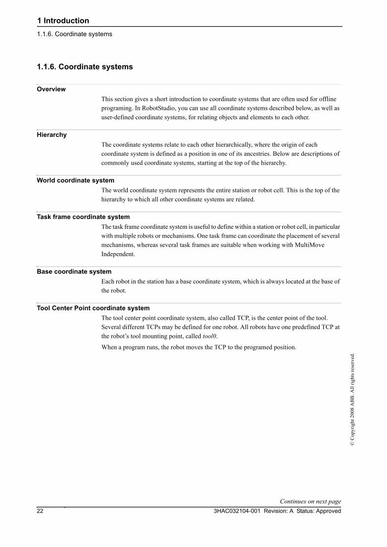
OverviewThis section gives a short introduction to coordinate systems that are often used for offline programing. In RobotStudio, you can use all coordinate systems described below, as well as user-defined coordinate systems, for relating objects and elements to each other.
HierarchyThe coordinate systems relate to each other hierarchically, where the origin of each coordinate system is defined as a position in one of its ancestries. Below are descriptions of commonly used coordinate systems, starting at the top of the hierarchy.
World coordinate systemThe world coordinate system represents the entire station or robot cell. This is the top of the hierarchy to which all other coordinate systems are related.
Task frame coordinate systemThe task frame coordinate system is useful to define within a station or robot cell, in particular with multiple robots or mechanisms. One task frame can coordinate the placement of several mechanisms, whereas several task frames are suitable when working with MultiMove Independent.
Base coordinate systemEach robot in the station has a base coordinate system, which is always located at the base of the robot.
Tool Center Point coordinate systemThe tool center point coordinate system, also called TCP, is the center point of the tool. Several different TCPs may be defined for one robot. All robots have one predefined TCP at the robot’s tool mounting point, called tool0.
When a program runs, the robot moves the TCP to the programed position.
Continues on next page

1 Introduction1.1.6. Coordinate systems
233HAC032104-001 Revision: A Status: Approved
© C
opyr
ight
200
8 A
BB
. All
right
s res
erve
d.
WorkObject coordinate systemThe workobject normally represents the physical work piece. It is composed of two coordinate systems: the User frame and the Object frame, where the latter is a child to the former. When programing a robot, all targets (positions) are related to the object frame of a workobject. If no other workobject is specified, the targets will be related to the default Wobj0, which always coincides with the base frame of the robot.
Using workobjects provides the chance to easily adjust robot programs with an offset, if the location of the work piece has been changed. Thus, workobjects can be used for calibrating offline programs. If the placement of the fixture/work piece relative to the robot in the real station does not completely match the placement in the offline station, you simply adjust the position of the workobject.
Workobjects are also used for coordinated motions. If a workobject is attached to a mechanical unit (and the system uses the option for coordinated motions), the robot will find the targets in the workobject even when the mechanical unit moves the workobject.
In the picture below the grey coordinate system is the world coordinate system, and the black ones are the object frame and the user frame of the workobject. Here the user frame is positioned at the table/fixture and the object frame at the workpiece.
xx0500001519
User Coordinate SystemsUser Coordinate Systems (UCSs) are used for creating reference points of your choice. For example, you can create UCSs at strategic points in the work piece to facilitate programing.
Continued

1 Introduction1.1.7. Robot axis configurations
3HAC032104-001 Revision: A Status: Approved24
© C
opyr
ight
200
8 A
BB
. All
right
s res
erve
d.
1.1.7. Robot axis configurations
Axis configurationsTargets are defined and stored as coordinates in a WorkObject coordinate system. When the controller calculates the position of the robot axes for reaching the target, it will often find more than one possible solution to configuring the robot axes.
xx0500002365
To distinguish between the different configurations, all targets have a configuration value that specifies the quadrant in which each axis shall be located.
Storing axis configurations in targetsFor targets that are taught after jogging the robot to the position, the used configuration will be stored in the target.
Targets created by specifying or calculating positions and orientations get a default configuration value (0,0,0,0), which might not be valid for reaching the target.
Common problems related to robot axis configurationsIt is most likely that targets created by other ways than jogging cannot be reached at their default configuration.
Even if all targets in a path have validated configurations, you might encounter problems when running the path if the robot cannot move from one configuration to the other. This is likely to occur where an axis shifts greater than 90 degrees during linear movements.
Repositioned targets keep their configuration, but the configurations are no longer validated. As a result, the problems described above might occur when moving targets.
Common solutions for configuration problemsTo resolve the problems described above, you can assign a valid configuration to each target and verify that the robot can move along each path. You can also turn configuration monitoring off, which means that you ignore the stored configurations and let the robot find working configurations at runtime. If this is not done the proper way, you might get unexpected results.
In some cases there might not be any working configurations. Possible solutions might then be to reposition the work piece, reorient targets (if acceptable for the process) or add an external axis that either moves the work piece or the robot for increasing reachability.
Continues on next page

1 Introduction1.1.7. Robot axis configurations
253HAC032104-001 Revision: A Status: Approved
© C
opyr
ight
200
8 A
BB
. All
right
s res
erve
d.
How configurations are denotedThe robot’s axis configurations are denoted by a series of four integers, specifying in which quadrant of a full revolution significant axes are located. The quadrants are numbered from zero for positive (counterclockwise) rotation and from -1 for negative (clockwise) rotation.
For a linear axis, the integer specifies the range (in meters) from the neutral position in which the axis is located.
A configuration for a six-axis industrial robot (like IRB 140) may look like:
[0 -1 2 1]
The first integer (0) specifies the position of axis 1: somewhere in the first positive quadrant (between 0 and 90 degrees rotation).
The second integer (-1) specifies the position of axis 4: somewhere in the first negative quadrant (between 0 and -90 degrees rotation).
The third integer (2) specifies the position of axis 6: somewhere in the third positive quadrant (between 180 and 270 degrees rotation).
The fourth integer (1) specifies the position of axis x, a virtual axis used for specifying the wrist center in relation to other axes.
Configuration monitoringWhen executing a robot program, you can choose whether to monitor configuration values. If configuration monitoring is turned off, configuration values stored with the targets are ignored, and the robot will use the configuration closest its current configuration for reaching the target. If turned on, it will only use the specified configuration for reaching the targets.
Configuration monitoring can be turned off and on for joint and linear movements independently and is controlled by the ConfJ and ConfL action instructions.
Turning configuration monitoring offRunning a program without configuration monitoring may result in different configurations each time a cycle is executed: When the robot returns to the start position after completing a cycle, it may choose a different configuration then the original.
For programs with linear move instructions this might cause a situation where the robot gets closer and closer its joint limits and eventually will not be able to reach the target.
For programs with joint move instructions this might cause sweeping, unpredictable movements.
Turning configuration monitoring onRunning a program with configuration monitoring forces the robot to use the configurations stored with the targets. This results in predictable cycles and predictable motions. In some situations, however, like when the robot moves to a target from an unknown position, using configuration monitoring may limit the robot’s reachability.
When programing offline, you must assign a configuration to each target if the program shall be executed with configuration monitoring.
Continued

1 Introduction1.1.8. Libraries, geometries and CAD files
3HAC032104-001 Revision: A Status: Approved26
© C
opyr
ight
200
8 A
BB
. All
right
s res
erve
d.
1.1.8. Libraries, geometries and CAD files
OverviewFor programing or simulating in RobotStudio, you need models of your work pieces and equipment. Models for some standard equipment are installed as libraries or geometries with RobotStudio. If you have CAD models of your work pieces and custom equipment, these can be imported as geometries to RobotStudio. If you do not have CAD models, you can create them in RobotStudio.
Difference between geometries and librariesThe objects you import to a station can be either geometries or libraries.
Geometries are basically CAD files, which, when imported, are copied to the RobotStudio station.
Libraries are objects that have been saved in RobotStudio as external files. When you import a library, a link from the station to the library file is created. Accordingly, the station file does not grow in the same way as when importing geometries. Furthermore, besides the geometrical data, library files can contain RobotStudio-specific data. For example, if a tool is saved as a library, the tool data is saved together with the CAD data.
How geometries are constructedAn imported geometry is displayed as one part in the Objects browser. From RobotStudio’s Modeling tab, you can see the components of the geometry.
The top node of the geometry is called a Part. The part contains Bodies, which can be of the types solid, surface or curve.
Solid bodies are 3D objects, made up of Faces. You recognize a true 3D solid by this one body containing multiple faces.
Surface bodies are 2D objects of just one face. A part that contains several bodies with one face each that together constitute a 3D object is created from 2D surfaces, and is therefore not a true 3D solid. If these parts are not created correctly, they might cause problems both in their display and graphical programing. see Troubleshooting and optimizing geometries on page 56.
Curved bodies, represented by the body node alone in the Modeling browser, do not contain any child nodes.
From the Modeling tab, you can edit the parts by adding, moving, rearranging or deleting bodies. Thus, you can optimize existing parts by removing unnecessary bodies, as well as create new parts by grouping bodies.
Importing and converting CAD filesFor importing geometries from single CAD files, you use RobotStudio’s import function, see Importing a station component on page 53.
If you need to convert CAD files to other formats or want to change the default settings for the conversion before making the import, you can use the CAD converter installed with RobotStudio before making the import, see Converting CAD formats on page 55.
Continues on next page

1 Introduction1.1.8. Libraries, geometries and CAD files
273HAC032104-001 Revision: A Status: Approved
© C
opyr
ight
200
8 A
BB
. All
right
s res
erve
d.
Supported CAD formatsSome of the CAD formats require a separate license for being imported or converted by RobotStudio. The table below shows the supported CAD formats and whether a license is required:
You need licenses for both the source format and the target format when converting licensed formats.
Format File extensions License require-ment
Default target formats
Acis, reads/writes versions v6 to R18
sat No Iges, Step, Vdafs
Iges, reads to version 5.3, writes version 5.3
igs, iges Yes Acis, Step, Vdafs
Step, reads versions AP203 and AP214 (geometry only), writes version AP 214
stp, step, p21 Yes Acis, Step, Vdafs
Vdafs, reads to 2.0, writes 2.0
vda, vdafs Yes Acis, Iges, Step
Catia V4, reads versions 4.1.9 to 4.2.4
model, exp Yes Acis, Iges, Step, Vdafs
Catia V5, reads versions R2 - R18
CATPart, CATProduct
Yes Acis, Iges, Step, Vdafs
Pro/Engineer, reads versions 16 to Wildfire3
prt, asm Yes Acis, Iges, Step, Vdafs
Inventor, reads versions 6 to 12
ipt Yes Acis, Iges, Step, Vdafs
Vrml wrl, vrml,vrml1, vrml2 No RsGfx
Jupiter, up to 6.4 jt No RsGfx
STL stl No RsGfx
PLY ply No RsGfx
3DStudio 3ds No RsGfx
Continued
Continues on next page

1 Introduction1.1.8. Libraries, geometries and CAD files
3HAC032104-001 Revision: A Status: Approved28
© C
opyr
ight
200
8 A
BB
. All
right
s res
erve
d.
Mathematical versus graphical geometriesA geometry in a CAD file always has an underlying mathematical representation. Its graphical representation, displayed in the graphics window, is generated from the mathematical representation when the geometry is imported to RobotStudio, after which the geometry is referred to as a part.
For this kind of geometry, you can set the detail level of the graphical representation, thus reducing the file size and rendering time for large models and improving the visual display for small models you might want to zoom in on. The detail level only affects the visual display; paths and curves created from the model will be accurate both with coarse and fine settings.
A part can also be imported from a file that simply defines its graphical representation; in this case, there is no underlying mathematical representation. Some of the functions in RobotStudio,such as snap mode and creation of curves from the geometry, will not work with this kind of part.
To customize the detail level settings, see RobotStudio Options on page 160.
Continued

1 Introduction1.1.9. VSTA as the IDE
293HAC032104-001 Revision: A Status: Approved
© C
opyr
ight
200
8 A
BB
. All
right
s res
erve
d.
1.1.9. VSTA as the IDE
OverviewRobotStudio uses Microsoft Visual Studio Tools for Applications (VSTA) as its Integrated Development Environment (IDE), enabling advanced users to extend and customize its functionality. You can, for example, write an add-in in C# or VB.Net to create a toolbar or macro, debug code or inspect variable values during execution.
In addition, the Add-In browser acts as a single window for both VSTA add-ins and non-VSTA, RobotStudio-specific add-ins known as PowerPacs.
For a procedure, see Visual Studio Tools for Applications on page 294.
Types of add-insThe following add-ins may be available in the Add-In browser:
Using the shortcut menus of the Add-In browser, PowerPacs may be loaded or autoloaded, while VSTA add-ins may be added, loaded, unloaded, reloaded, autoloaded, edited, deleted, or removed from the station.
Object Description
PowerPac An add-in that accords with RobotStudio specifications, but is not part of the VSTA system itself.
VSTA Station Add-In A VSTA add-in that has been attached to a station, and saved to the station file.
VSTA User Add-In A VSTA add-in that has not been attached to a station and is active only on the current user’s computer.

1 Introduction1.2.1. The Getting Started window
3HAC032104-001 Revision: A Status: Approved30
© C
opyr
ight
200
8 A
BB
. All
right
s res
erve
d.
1.2 The Graphical User Interface
1.2.1. The Getting Started window
OverviewThe Getting Started window contains the following tabs:
Tab Description
Recent Stations Offline Use this tab to open recent stations (which are previewed), a new station or any saved station.
Recent Controllers Online Use this tab to open a recent controller, connect to a controller with one click or add a controller.
Information Use this tab to access help files, browse tutorials, connect to the online community, manage your licenses or browse RobotStudio news.

1 Introduction1.2.2. The Layout browser
313HAC032104-001 Revision: A Status: Approved
© C
opyr
ight
200
8 A
BB
. All
right
s res
erve
d.
1.2.2. The Layout browser
OverviewThe layout browser is a hierarchical display of physical items, such as robots and tools.
Icons
Icon Node Description
xx0500001364
Robot The robot in the station. The red lock in the lower right corner of the icon indicates that the object is connected to a library.
xx0500001365
Tool A tool.
xx0500001366
Link collection Contains all the links of the objects.
xx0500001367
Link A physical object in a joint connection. Each link is made up of one or several parts.
xx0500001478
Frames Contains all the frames for an object.
xx0500001368
Component group A grouping of parts or other assemblies, carrying its own coordinate systems. It is used to structure a station.
xx0500001369
Part A physical object in RobotStudio. Parts with geometric information are made up of one or more 2D or 3D entities. Parts without geometric information (such as imported .jt files) are empty.
xx0500001370
Collision set Contains all collision sets. Each collision set includes two groups of objects.
xx0500001371
Objects group Contains references to the objects that are subject to collision detection.
xx0500001479
Collision set mechanisms
The objects in the collision set.
xx0500001372
Frame The frames in the station.

1 Introduction1.2.3. The Paths & Targets browser
3HAC032104-001 Revision: A Status: Approved32
© C
opyr
ight
200
8 A
BB
. All
right
s res
erve
d.
1.2.3. The Paths & Targets browser
OverviewThe paths & targets browser is a hierarchical display of non-physical items.
Icons
Icon Node Description
xx0500001373
Station Your station in RobotStudio.
xx0500001374
Virtual Controller The system for controlling the robots, just like a real IRC5 controller.
xx0500001375
Task Contains all logical elements in the station, such as targets, paths, workobjects, tooldata and instructions.
xx0500001376
Tooldata Collection Contains all tooldata.
xx0500001471
Tooldata A tooldata for a robot or a task.
xx0500001377
Workobjects & Targets Contains all workobjects and targets for the task or robot.
xx0500001477
Jointtarget Collection and Jointtarget
A specified position of the robot axes.
xx0500001378
Workobject Collection and Workobject
The workobject collection node and the workobjects it contains.
xx0500001379
Target A defined position and rotation for a robot. A target equals a RobTarget in a RAPID program.
xx0500001849
Target without assigned configuration
A target for which no axis configuration has been assigned, for example, a repositioned target or a new target created by means other than teaching.
xx0500001850
Target without found con-figuration
An unreachable target, that is, for which no axis configuration has been found.
xx0500001380
Path Collection Contains all paths in the station.
Continues on next page

1 Introduction1.2.3. The Paths & Targets browser
333HAC032104-001 Revision: A Status: Approved
© C
opyr
ight
200
8 A
BB
. All
right
s res
erve
d.
xx0500001381
Path Contains the instructions for the robot movements.
xx0500001474
Linear Move Instruction A linear TCP motion to a target. If the target has no valid configuration assigned, the move instruction gets the same warning symbols as the target.
xx0500001851
Joint Move Instruction A joint motion to a target. If the target has no valid configuration assigned, the move instruction gets the same warning symbols as the target.
xx0500001475
Action Instruction Defines an action for the robot to perform at a specified location in a path.
Icon Node Description
Continued

1 Introduction1.2.4. The Modeling browser
3HAC032104-001 Revision: A Status: Approved34
© C
opyr
ight
200
8 A
BB
. All
right
s res
erve
d.
1.2.4. The Modeling browser
OverviewThe modeling browser is a display of editable objects and their building blocks.
Icons
Icon Node Description
xx0600002704
Part Geometric items corresponding to the objects in the Layout browser.
xx0600002705
Body Geometric building blocks that comprise the parts. 3D bodies contain several faces, 2D bodies one face, and curves no faces.
xx0600002706
Face The faces of the bodies.

1 Introduction1.2.5. The Offline and Online browsers
353HAC032104-001 Revision: A Status: Approved
© C
opyr
ight
200
8 A
BB
. All
right
s res
erve
d.
1.2.5. The Offline and Online browsers
OverviewThe offline and online browsers is a hierarchical display of controller and configuration elements.
Icons
Icon Node Description
xx0300000026
Controllers Contains the controllers that are connected to the Robot View.
xx0300000027
Connected Controller Represents a controller with a working connection.
xx0400000677
Connecting Controller Represents a controller which is currently being connected.
xx0300000028
Disconnected Controller Represents a controller that has lost its connection. It might have been turned off or disconnected from the network.
xx0600003287
Denied login Represent a controller that denies you access to login. Possible reasons for denied access:
• The user lacks grant to login• Too many clients connected to the controller• The RobotWare version of the system running on the
controller is newer than the version of RobotStudio Online
xx0300000029
Configuration Contains the configuration topics.
xx0300000030
Topic Each parameter topic is represented by a node: • Communication • Controller• I/O • Man-machine communication• Motion
xx0300000037
Event Log With the Event Log you can view and save controller events.
xx0300000434
I/O System Represents the controller I/O system. The I/O system consists of I/O buses and units.
Continues on next page

1 Introduction1.2.5. The Offline and Online browsers
3HAC032104-001 Revision: A Status: Approved36
© C
opyr
ight
200
8 A
BB
. All
right
s res
erve
d.
xx0300000433
I/O Bus An I/O bus is a connector for one or several I/O units.
xx0300000432
I/O Unit An I/O Unit is a board, panel or any other device with ports through which the I/O signals are sent.
xx0300000031
RAPID Tasks Contains the active tasks (programs) of the controller.
xx0300000032
Task A task is a robot program, which executes alone or together with other programs. A program is composed of a set of modules.
xx0300000431
Modules A container for either program modules or system modules.
xx0300000430
Program Module A program module contains a set of data declarations and routines for a specific task. Program modules contains data specific for this program.
xx0300000428
System Module A system module contains a set of type definitions, data decla-rations and routines. System modules contains data that applies to the robot system, regardless which program modules that are loaded.
xx
Encrypted Module A module that is locked for editing and viewing.
xx
Nostepin Module A module that cannot be entered during step-by-step execution. That is all instructions in the module are treated as one if the program is executed step-by-step.
xx0300000429
Procedure A routine that does not return any value. Procedures are used as subprograms.
xx0300000034
Function A routine that returns a value of a specific type.
xx0300000036
Trap A routine that provides a means of responding to interrupts.
xx0300000039
Documents Folder Folder for links to documents and files.
Continued
Continues on next page

1 Introduction1.2.5. The Offline and Online browsers
373HAC032104-001 Revision: A Status: Approved
© C
opyr
ight
200
8 A
BB
. All
right
s res
erve
d.
xx0300000038
Document Link Link to a document. The icon for the document is the same as the Window icon for the document type.
Continued

1 Introduction1.2.6. The Output window
3HAC032104-001 Revision: A Status: Approved38
© C
opyr
ight
200
8 A
BB
. All
right
s res
erve
d.
1.2.6. The Output window
OverviewThe output window displays information about events that occur in the station, such as when simulations are started or stopped. This information is useful when troubleshooting stations.
Layout of the Output tabThe Output tab contains two columns: the first states the event, the second the time the message was generated. Each row is a message.
Event typesThe three event types indicate the severity of the event:
Some of the events are active. These are linked to an action for resolving the problem that generated the event. To activate the linked action, double-click the message.
Handling messages in the Output window
Event type Description
Information An information message is a normal system event, for example, starting and stopping programs, changing the operational mode, and turning motors on and off.Information messages never require an action from you. They can be useful for tracking errors, collecting statistics or monitoring user-triggered event routines.
Warning A warning is an event of which you should be aware, but it is not so severe that the process or RAPID program needs to be stopped.Warnings must occasionally be acknowledged. Warnings often indicate underlying problems that at some point will need to be resolved.
Error An error is an event that prevents the robot system from proceeding. The running process or RAPID program cannot continue and will be stopped.An error must occasionally be acknowledged. Some errors require some immediate action from you in order to be resolved. Double-click an error to display a detailed information box.
Goal Procedure
To filter messages... Right-click in the Output window and then click Show messages. From the options All Errors, information, Warningsand Warnings and Errors, select the type of messages you want to display.
To save a message to file... Select it, right-click and then click Save to file. Choose a name and location in the dialog box. Multiple messages can be selected by pressing SHIFT while clicking each.
To clear the Output window...
Right-click in the Output window and then click Clear.
Continues on next page

1 Introduction1.2.6. The Output window
393HAC032104-001 Revision: A Status: Approved
© C
opyr
ight
200
8 A
BB
. All
right
s res
erve
d.
The Controller tabThe controller status window shows the operational status of the controllers in your robot view.
1. The System Name column
This column shows the name of the system that is running on the controller.
2. The Controller Name column
This column shows the name of the controller.
3. The Controller State column
This column shows the state of the controller:
4. The Program Execution State column
This column shows if the robot is running any program or not:
5. The Operating Mode column
This column shows the operating mode of the controller:
When the controller is in state... the robot is...
Initializing starting up. It will shift to state motors off when it has started.
Motors off in a standby state where there is no power to the robot's motors. The state has to be shifted to motors on before the robot can move.
Motors on ready to move, either by jogging or by running programs.
Guard Stop stopped because the safety runchain is opened. For instance, a door to the robot's cell might be open.
Emergency Stop stopped because emergency stop was activated.
Waiting for motors on after e-stop
ready to leave emergency stop state. The emergency stop is no longer activated, but the state transition isn't yet confirmed.
System Failure in a system failure state. A warm start is required.
When the controller is in state... the robot...
Running is running a program.
Ready has a program loaded and is ready to run it when a PP (starting point in the program) has been set.
Stopped has a program loaded, with a PP, and is ready to run it.
Uninitialized has not initialized the program memory. This indicates an error condition.
When the controller is in mode... the robot is...
Initializing starting up. It will shift to the mode selected on the controllers cabinet when it has started.
Auto ready to run programs in production. In Auto mode it is possible to get remote Write access to the controller, which is necessary for editing programs, configurations and other things with RobotStudio Online.
Continued
Continues on next page
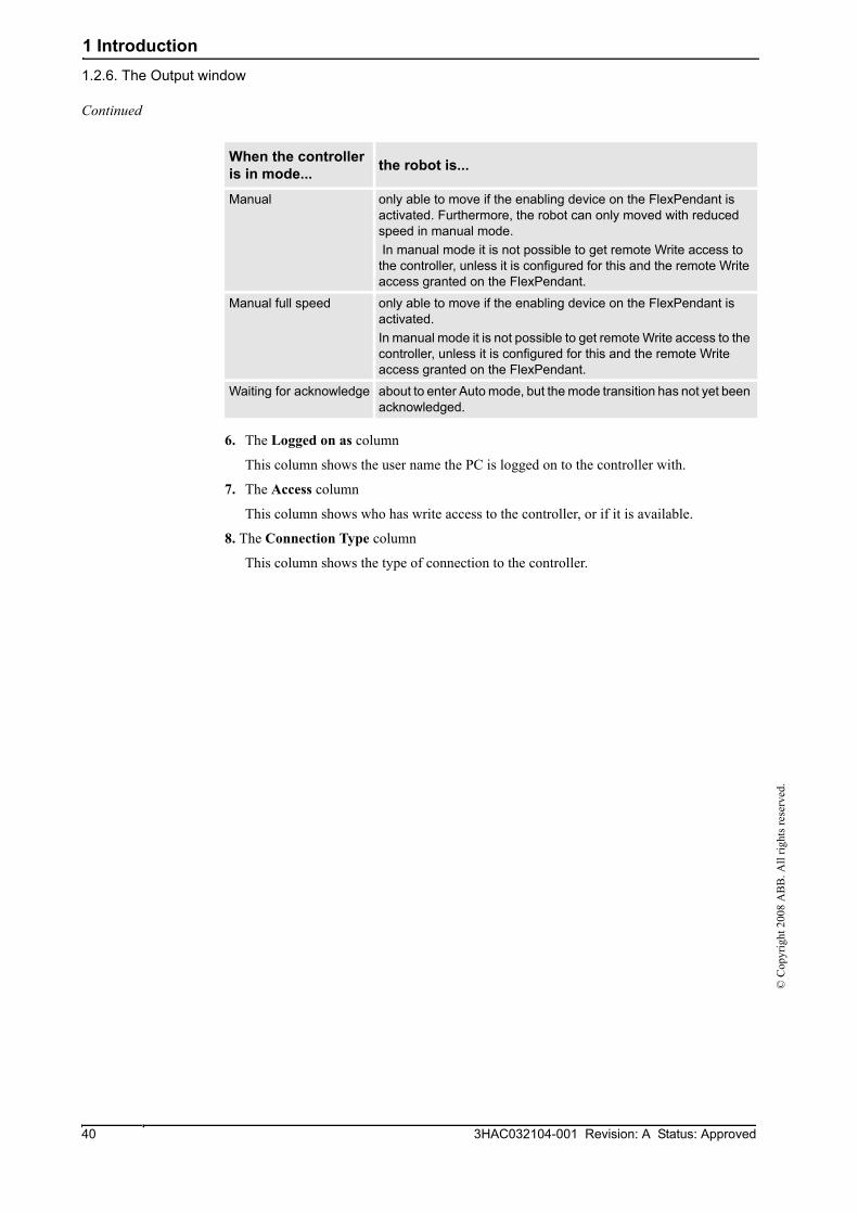
1 Introduction1.2.6. The Output window
3HAC032104-001 Revision: A Status: Approved40
© C
opyr
ight
200
8 A
BB
. All
right
s res
erve
d.
6. The Logged on as column
This column shows the user name the PC is logged on to the controller with.
7. The Access column
This column shows who has write access to the controller, or if it is available.
8. The Connection Type column
This column shows the type of connection to the controller.
Manual only able to move if the enabling device on the FlexPendant is activated. Furthermore, the robot can only moved with reduced speed in manual mode. In manual mode it is not possible to get remote Write access to the controller, unless it is configured for this and the remote Write access granted on the FlexPendant.
Manual full speed only able to move if the enabling device on the FlexPendant is activated. In manual mode it is not possible to get remote Write access to the controller, unless it is configured for this and the remote Write access granted on the FlexPendant.
Waiting for acknowledge about to enter Auto mode, but the mode transition has not yet been acknowledged.
When the controller is in mode... the robot is...
Continued

1 Introduction1.2.7. Using a mouse
413HAC032104-001 Revision: A Status: Approved
© C
opyr
ight
200
8 A
BB
. All
right
s res
erve
d.
1.2.7. Using a mouse
Navigating the graphics window using the mouseThe table below shows how to navigate the graphics window using the mouse:
To Use the keyboard /mouse combination Description
Select items
xx0500002417 xx0500002421
Just click the item to select. To select multiple items, press CTRL key while clicking new items.
Rotate the station
xx0500002424
CTRL + SHIFT +
xx0500002421
Press CTRL + SHIFT + the left mouse button while dragging the mouse to rotate the station. With a 3-button mouse you can use the middle and right buttons, instead of the keyboard combination.
Pan the station
xx0500002422
CTRL +
xx0500002421
Press CTRL + the left mouse button while dragging the mouse to pan the station.
Zoom the station
xx0500002426
CTRL +
xx0500002423
Press CTRL + the right mouse button while dragging the mouse to the left to zoom out. Dragging to the right zooms in.With a 3-button mouse you can also use the middle button, instead of the keyboard combination.
Zoom using window
xx0500002425
SHIFT +
xx0500002423
Press SHIFT + the right mouse button while dragging the mouse across the area to zoom into.
Select using window
xx0500002428
SHIFT +
xx0500002421
Press SHIFT + the left mouse button while dragging the mouse across the area to select all items that match the current selection level.
1 Introduction1.2.8. Selecting an item
3HAC032104-001 Revision: A Status: Approved42
© C
opyr
ight
200
8 A
BB
. All
right
s res
erve
d.
1.2.8. Selecting an item
OverviewEach item in a station can be moved to achieve the required layout, so you first have to determine its selection level. The selection level makes it possible to select only specific types of items, or specified parts of objects.
The selection levels are curve, surface, entity, part, mechanism, group, target/frame and path. The target/frame and path selection can be combined with any of the other selection levels.
Objects may also be grouped together as component groups, see Component Group on page 198.
Selecting an item in the graphics windowTo select items in the graphics window, follow these steps:
1. At the top of the graphics window, click the desired selection level icon.
2. Optionally, click the desired snap mode icon for the part of the item you wish to select.
3. In the graphics window, click the item. The selected item will be highlighted.
Multiple selection of items in the graphics windowTo select multiple items in the graphics window, do the following:
1. Press the SHIFT key, and in the graphics window drag the mouse diagonally over the objects to select.
Selecting an item in the browsersTo select items in a browser, do the following:
1. Click the item. The selected item will be highlighted in the browser.
Multiple selection of items in the browsersTo select multiple items in a browser, follow these steps:
1. Make sure that all the items to be selected are of the same type and located in the same branch of the hierarchical structure; otherwise, the items will not be operable.
2. Do one of the following:
• To select adjacent items: In the browser, hold down the SHIFT key and click the first and then the last item. The list of items will be highlighted.
• To select separate items: In the browser, hold down the CTRL key and click the items you want to select. The items will be highlighted.

1 Introduction1.2.9. Attaching and detaching objects
433HAC032104-001 Revision: A Status: Approved
© C
opyr
ight
200
8 A
BB
. All
right
s res
erve
d.
1.2.9. Attaching and detaching objects
Overview You can attach an object (child) to another object (parent). Attachments can be created on part level and on mechanism level. When an object has been attached to a parent, moving the parent also moves the child.
One of the most common attachments is to attach a tool to a robot. For procedures, see Attach to on page 299 and Detach on page 307.
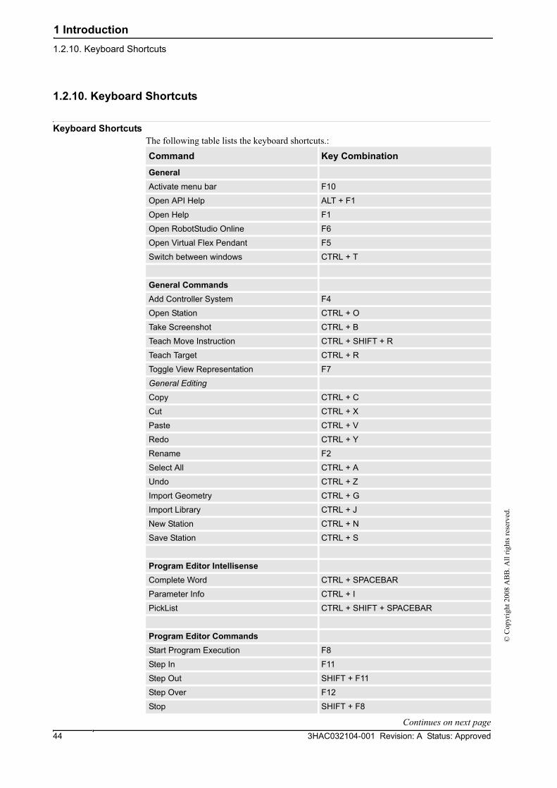
1 Introduction1.2.10. Keyboard Shortcuts
3HAC032104-001 Revision: A Status: Approved44
© C
opyr
ight
200
8 A
BB
. All
right
s res
erve
d.
1.2.10. Keyboard Shortcuts
Keyboard ShortcutsThe following table lists the keyboard shortcuts.:
Command Key Combination
General
Activate menu bar F10
Open API Help ALT + F1
Open Help F1
Open RobotStudio Online F6
Open Virtual Flex Pendant F5
Switch between windows CTRL + T
General Commands
Add Controller System F4
Open Station CTRL + O
Take Screenshot CTRL + B
Teach Move Instruction CTRL + SHIFT + R
Teach Target CTRL + R
Toggle View Representation F7
General Editing
Copy CTRL + C
Cut CTRL + X
Paste CTRL + V
Redo CTRL + Y
Rename F2
Select All CTRL + A
Undo CTRL + Z
Import Geometry CTRL + G
Import Library CTRL + J
New Station CTRL + N
Save Station CTRL + S
Program Editor Intellisense
Complete Word CTRL + SPACEBAR
Parameter Info CTRL + I
PickList CTRL + SHIFT + SPACEBAR
Program Editor Commands
Start Program Execution F8
Step In F11
Step Out SHIFT + F11
Step Over F12
Stop SHIFT + F8
Continues on next page

1 Introduction1.2.10. Keyboard Shortcuts
453HAC032104-001 Revision: A Status: Approved
© C
opyr
ight
200
8 A
BB
. All
right
s res
erve
d.
Toggle Breakpoint F9
Apply Changes CTRL + SHIFT + S
Check Program SHIFT + F5
Print CTRL + P
Program Editor Hotkeys
Copy CTRL + Insert
Cut SHIFT + Delete
Cut marked lines CTRL + L
Delete marked lines CTRL + SHIFT + L
Delete to beginning of word CTRL + BACKSPACE
Delete to end of word CVTRL + Delete
Indent Tab
Make the selected text lowercase CTRL + SHIFT + U
Make the selected text uppercase CTRL + U
Move to beginning of document CTRL + Home
Move to beginning of line Home
Move to end of document CTRL + End
Move to end of line End
Move to next word CTRL + Right
Move to previous word CTRL + Left
Move to visible bottom CTRL + Page Down
Move to visible top CTRL + Page Up
Open line above CTRL + Enter
Open line below CTRL + SHIFT + Enter
Outdent SHIFT + Tab
Paste SHIFT + Insert
Redo CTRL + SHIFT + Z
Scroll down CTRL + Down
Scroll up CTRL + Up
Select block down ALT + SHIFT + Down
Select block left ALT + SHIFT + Left
Select block right ALT + SHIFT + Right
Select block to next word CTRL + ALT + SHIFT + Right
Select block to previous word CTRL + ALT + SHIFT + Left
Select block up ALT + SHIFT + Up
Select down SHIFT + Down
Select left SHIFT + Left
Select page down SHIFT + Page Down
Select page up SHIFT + Page Up
Select right SHIFT + Right
Select to beginning of document CTRL + SHIFT + Home
Select to beginning of line SHIFT + Home
Command Key Combination
Continued
Continues on next page

1 Introduction1.2.10. Keyboard Shortcuts
3HAC032104-001 Revision: A Status: Approved46
© C
opyr
ight
200
8 A
BB
. All
right
s res
erve
d.
Select to end of document CTRL + SHIFT + End
Select to end of line SHIFT + End
Select to next word CTRL + SHIFT + Right
Select to previous word CTRL + SHIFT + Left
Select to visible bottom CTRL + SHIFT + Page Down
Select to visible top CTRL + SHIFT + Page Up
Select up SHIFT + Up
Select word CTRL + SHIFT + W
Toggle overwrite mode Insert
Transpose characters CTRL + T
Transpose lines CTRL + ALT + SHIFT + T
Transpose words CTRL + SHIFT + T
Command Key Combination
Continued

2 How to build stations1.2.10. Keyboard Shortcuts
473HAC032104-001 Revision: A Status: Approved
© C
opyr
ight
200
8 A
BB
. All
right
s res
erve
d.
2 How to build stations

2 How to build stations2.1. Workflow for building a new station
3HAC032104-001 Revision: A Status: Approved48
© C
opyr
ight
200
8 A
BB
. All
right
s res
erve
d.
2.1. Workflow for building a new station
OverviewThis is an overview of how to build a station by including the equipment necessary to create and simulate robot programs.
The first part of this overview describes the alternatives for creating a station with a system. The second part describes importing or creating the objects to work with. The third part describes the workflow for optimizing the station layout by finding the best placement of robots and other equipment.
In most cases, following the workflows from start to finish is recommended, even if other sequences are also possible.
Creating a station with a systemThe table below shows the alternatives for creating a station with a system.
For procedures, see New Station on page 156.
Manually starting the VCThe table below shows the alternatives for manually starting with a system. Perform only those steps applicable to your station.
Importing station componentsThe table below shows the workflow for importing station components. Perform only those steps applicable to your station.
For procedures, see Importing a station component on page 53.
Activity Description
Create a station with a template system
This is the simplest way to create a new station containing a robot and a link to a rudimentary system template.
Create a station with an existing system
This creates a new station containing one or more robots in accordance with an existing, built system.
Create a station with no system
An advanced user can build a station from scratch and then add a new or existing system to it.
Activity Description
Manually connecting a library to the VC
See Starting a VC on page 50.
Restarting the VC See Restarting a VC on page 52.
Activity Description
Import a robot model See Robot System on page 170.
Import a tool See Import Library on page 169.
Import a positioner See ABB Library on page 168.
Import a track See Import Library on page 169.
Import other equipment If you have CAD models of the equipment, you can import them, see Import Library on page 169. Otherwise, you can create models in RobotStudio, see Mechanisms on page 60.
Continues on next page

2 How to build stations2.1. Workflow for building a new station
493HAC032104-001 Revision: A Status: Approved
© C
opyr
ight
200
8 A
BB
. All
right
s res
erve
d.
Placing objects and mechanismsThe table below shows the workflow for placing the objects in the station.
Add work piece If you have CAD models of the work piece, you can import them, see Workobject on page 176. Otherwise, you can create models in RobotStudio, see Objects on page 58.
Activity Description
Activity Description
Place objects If you are building a model of a real station, start by placing all objects with known positions. For objects without known positions, find a suitable placement, see Placing objects on page 63 and Placing external axes on page 64.
Attach tools Attach the tools to the robot, see Attach to on page 299.
Attach robots to tracks If track external axes are used, attach the robots to the tracks, see Attach to on page 299.
Attach work pieces to positioners
If positioner external axes are used, attach the work pieces to the positioners, see Attach to on page 299.
Test reachability Test if the robot can reach critical positions on the work piece. If you are satisfied with how the robot reaches the positions, your station is ready for programing. Otherwise, continue adjusting the placement or trying other equipment as described below, see Testing positions and motions on page 86.
Continued

2 How to build stations2.2.1. Starting a VC
3HAC032104-001 Revision: A Status: Approved50
© C
opyr
ight
200
8 A
BB
. All
right
s res
erve
d.
2.2 The VC
2.2.1. Starting a VC
OverviewRobotStudio uses virtual controllers for running the robots. Virtual controllers can run both systems for real robots and specific virtual systems for testing and evaluation purposes. A virtual controller uses the same software as the controller to execute the RAPID program, to calculate robot motions and to handle I/O signals.
When starting a virtual controller, point out which system to run on it. Since the system contains information about the robots to use and important data such as robot programs and configurations, it is important to select the right system for the station.
Starting a VCThe table below describes the different ways a virtual controller may start:
Startup Description
Automatic, when creating a station
In most cases, a VC is automatically started when you create a new station. Library files for the robots used by the system are then imported to the station.
Automatic, when adding a system to an existing station
If your station uses several systems or if you started with an empty station, you can add systems to an open station. Library files for the robots used by the the systems are then imported to the station.
Manually, when connecting to an imported library
If you have manually imported a robot library you want to use with a system, instead of importing a new library at startup, you can connect this library to a controller.If you have manually imported a robot library you want to use with a system, instead of importing a new library at startup, you can connect this library to a controller.A library may only be connected to a single-robot system and may not be already connected to another VC.
Continues on next page

2 How to build stations2.2.1. Starting a VC
513HAC032104-001 Revision: A Status: Approved
© C
opyr
ight
200
8 A
BB
. All
right
s res
erve
d.
Adding a system To start a system in a new virtual controller and automatically import the robots used by the system, follow these steps:
1. • If you have the Select system dialog box open, continue with the next step.
• If you do not have the Select system dialog box open, go to the Controller menu and click Add System.
2. Depending on whether the system to start on the virtual controller is ready or not, do one of the following:
3. From the Systems Found list, select the system to use and click Start.
Activity Description
Create and start a copy of an existing systemThis is recommended when you plan to add station-specific configurations or programs.
From the Select system pool list, select the folder on your PC that contains the system to use. Select the system to copy from the Systems Found list and click Copy. In the Copy System dialog box, enter a name for the system and click OK.
Start an existing system as isThis is useful when you already have created a specific system for the station.It is also useful if you do not plan to create station-specific configurations or programs and want a quick start.
From the Select system pool list, select the folder on your PC that contains the system to use.
Modify and start an existing systemThis is the way to add or change options in the systems, for example, adding or replacing robots and external axes.
From the Select system pool list, select the folder on your PC that contains the system to modify. Select the system to modify from the Systems Found list and click Modify. This starts the System Builder from which you make the modifications. For detailed informa-tion, see Modifying a system on page 130.
Build and start a new systemThis option is used for building and starting a completely new system, either from RobotWare keys or from virtual keys.
Click Create to start the System Builder from which you build the new system. For detailed information about creating the system, see Building a new system on page 127.
Continued

2 How to build stations2.2.2. Restarting a VC
3HAC032104-001 Revision: A Status: Approved52
© C
opyr
ight
200
8 A
BB
. All
right
s res
erve
d.
2.2.2. Restarting a VC
OverviewThis section describes when and how to restart a VC in RobotStudio.
See also Restart on page 263.
When to restart a virtual controllerSome operations require a restart of the controller to take effect. When working in RobotStudio, you will be notified when a restart is necessary.
Warm restartTypically, you need to make an ordinary warm restart of a virtual controller when:
• you have changed the baseframe of any of the robots belonging to that virtual controller.
• you have changed the robot's configuration, either with the Configuration Editor or by loading new configuration files.
• you have added new options or hardware to the system.
• A system failure has occurred.
Cold restartA cold restart is useful for restoring the system running on a virtual controller to the state it was created in. The cold restart deletes all RAPID programs, data and custom configurations that have been added to the system.
Advanced restartsIn addition to warm and cold restarts, several advanced restarts are available.

2 How to build stations2.3.1. Importing a station component
533HAC032104-001 Revision: A Status: Approved
© C
opyr
ight
200
8 A
BB
. All
right
s res
erve
d.
2.3 Station components
2.3.1. Importing a station component
Importing a robot modelThis is how to import a robot model without a controller to your station.
A robot which is not connected to a controller cannot be programed. To import a robot connected to a virtual controller, configure a system for the robot and start it in a virtual controller, see Building a new system on page 127 and Starting a VC on page 50, respectively.
To import a robot model, in the Home tab, click Robot System and then select a robot model from the gallery.
Importing a toolA tool is a special object, for example, an arc weld gun or a gripper, that operates on the work piece. For achieving correct motions in robot programs, the parameters of the tool have to be specified in the tool data. The most essential part of the tool data is the TCP, which is the position of the tool center point relative to the wrist of the robot (which is the same as the default tool, tool0).
When imported, the tool will not be related to the robot. So in order for the tool to move with the robot, you must attach it to the robot.
To import a tool, in the Home tab, click Tool and then select a tool from the gallery.
Importing a positionerTo import a tool, in the Home tab, click Positioner and then select a positioner from the gallery.
Adding the track to the systemTo select the model of the external axis to use, follow these steps:
1. Start the system in a virtual controller, either in a new empty station or in an existing station, see Robot System on page 170.
2. In the Layout browser, select the system to add the track to.
3. On the Offline tab, click System Configuration.
4. Click Add to add parameters for the track to the system. Browse to the parameter file (.cfg) for the track to add and click Open.
If you have a specific parameter file for you track, use that one. Otherwise, parameter files for some standard tracks are delivered with the RobotStudio installation. These can be found in the folder ABB Library/ Tracks in RobotStudio’s installation folder. The ABB Library folder can also be opened from the Quick access pane at the left of the Open dialog box used for adding parameter files.
The file name of each parameter file tells which tracks it supports. The first part tells the length of the track and the second the number of tasks. For example, the file TRACK_1_7.cfg supports all tracks with the length 1.7 meters in systems with one single task. For Multimove systems or other systems with several tasks, use the configuration file with the matching number of tasks.
Continues on next page

2 How to build stations2.3.1. Importing a station component
3HAC032104-001 Revision: A Status: Approved54
© C
opyr
ight
200
8 A
BB
. All
right
s res
erve
d.
5. In the System Configuration window, click OK. When asked if you want to restart the system, answer Yes.
6. During the restart a list of all tracks compatible with the configuration file is displayed. Select the one to use and click OK.
After the restart the track appears in the station. Continue with attaching the robot to the track.
Importing a library, geometry or piece of equipmentA library component is a RobotStudio object that has been saved separately. Normally, components in a library are locked for editing.
A geometry is CAD data which you can import to use in RobotStudio. For a list of importable CAD formats, see Libraries, geometries and CAD files on page 26.
To import a library, geometry or piece of equipment, see Import Library on page 169.
Continued

2 How to build stations2.3.2. Converting CAD formats
553HAC032104-001 Revision: A Status: Approved
© C
opyr
ight
200
8 A
BB
. All
right
s res
erve
d.
2.3.2. Converting CAD formats
OverviewA CAD converter is installed together with RobotStudio by default. In most cases you do not have to convert CAD files before importing them to RobotStudio, but the CAD converter might be useful for converting several files at once, or for converting with custom settings.
PrerequisitesMost of the file formats require separate licenses, see Libraries, geometries and CAD files on page 26 for more information.
Starting the CAD converterClick Start menu, point to Programs, ABB Industrial IT, Robotics IT and click CAD Converter.
Converting CAD filesTo convert CAD files, follow these steps:
1. Click Add files and select the files to convert. Optionally, click Add files, again to add more files from another location.
Each file is now added to a row in the grid.
2. Optionally, change the suggested file name or target format by clicking that column for the file to change.
3. In the Target directory box, specify the folder in which to save the new files.
4. Optionally, click Settings and change the settings for the conversion. For details about the conversion settings, see Conversion settings on page 55.
5. Click Convert Files.
Conversion settingsThe table below describes the settings for the conversion:
Setting Description
Acis save file format Select which version of ACIS to save to when using ACIS as target format.
Enable Healing Controls whether the conversion engine attempts to heal geometric entities. Only supported for specified formats.
Translate hidden/no-show entities
Controls whether the hidden entities are translated or discarded. Only supported for specified formats.
VRML/STL Scale factors VRML and STL are often created in units that RobotStudio does not expect; they thus need to be resized.
Delete all generated log files on exit
Makes the CAD converter delete log files when exiting.
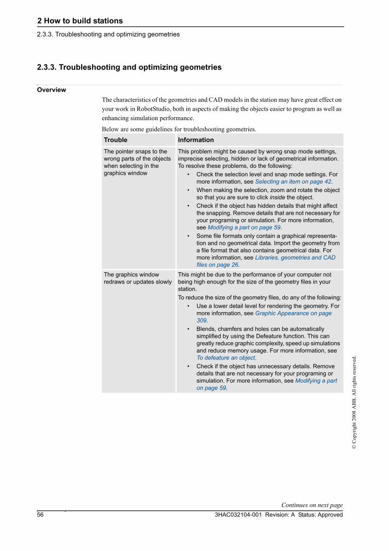
2 How to build stations2.3.3. Troubleshooting and optimizing geometries
3HAC032104-001 Revision: A Status: Approved56
© C
opyr
ight
200
8 A
BB
. All
right
s res
erve
d.
2.3.3. Troubleshooting and optimizing geometries
OverviewThe characteristics of the geometries and CAD models in the station may have great effect on your work in RobotStudio, both in aspects of making the objects easier to program as well as enhancing simulation performance.
Below are some guidelines for troubleshooting geometries.
Trouble Information
The pointer snaps to the wrong parts of the objects when selecting in the graphics window
This problem might be caused by wrong snap mode settings, imprecise selecting, hidden or lack of geometrical information. To resolve these problems, do the following:
• Check the selection level and snap mode settings. For more information, see Selecting an item on page 42.
• When making the selection, zoom and rotate the object so that you are sure to click inside the object.
• Check if the object has hidden details that might affect the snapping. Remove details that are not necessary for your programing or simulation. For more information, see Modifying a part on page 59.
• Some file formats only contain a graphical representa-tion and no geometrical data. Import the geometry from a file format that also contains geometrical data. For more information, see Libraries, geometries and CAD files on page 26.
The graphics window redraws or updates slowly
This might be due to the performance of your computer not being high enough for the size of the geometry files in your station.To reduce the size of the geometry files, do any of the following:
• Use a lower detail level for rendering the geometry. For more information, see Graphic Appearance on page 309.
• Blends, chamfers and holes can be automatically simplified by using the Defeature function. This can greatly reduce graphic complexity, speed up simulations and reduce memory usage. For more information, see To defeature an object.
• Check if the object has unnecessary details. Remove details that are not necessary for your programing or simulation. For more information, see Modifying a part on page 59.
Continues on next page

2 How to build stations2.3.3. Troubleshooting and optimizing geometries
573HAC032104-001 Revision: A Status: Approved
© C
opyr
ight
200
8 A
BB
. All
right
s res
erve
d.
To invert the direction of all faces of a partTo invert the direction of all faces of a part, follow these steps:
1. Select the part on which faces you want to invert the directions.
2. On the Modify menu, click Graphic Appearance.
3. On the Rendering tab, click Flip normals and then click OK.
To deactivate backface culling for a single objectTo change the backface culling setting for a single object, follow these steps:
1. Select the part for which you want to change the backface culling setting.
2. On the Modify menu, click Graphic Appearance.
3. On the Rendering tab, clear the Backface culling check box and then click OK. The faces of the object will now be displayed even if the generic setting for backface culling is on.
To change the generic setting for backface cullingThe generic setting for backface culling affects all new objects and existing objects that do not have backface culling specifically deactivated.
1. On the Application menu, click RobotStudio Options.
2. On the Navigation pane to the left, select Graphics: Performance.
3. On the Performance page, select or clear the Cull back-facing triangles check box and then click OK.
Parts of the geometry are not visible
If parts of the geometry are not visible from some views, a probable cause is that the object is made up of 2D surfaces and the option Backface culling is on.Backface culling means that the faces of the object are only visible from the front, and if the object (or any of its faces) is oriented differently, they will not be visible. To correct the problem, do one of the following:
• Switch to modeling mode and invert the direction of the face that is not displayed correctly. This not only corrects the display, it also decreases the chance of faulty orien-tations during graphical programing. For more informa-tion, see Invert on page 312 or To invert the direction of all faces of a part on page 57.
• Turn backface culling off for the specific object. This makes the object display correctly, but does not affect the direction of the face, which might cause problems if the face will be used for graphical programing. For more information, see To deactivate backface culling for a single object on page 57.
• Turn backface culling off for all objects in the station. This makes the objects display correctly, but does not affect the direction of the face, which might cause problems if the face will be used for graphical programing. It also decreases the performance of the graphic handling. For more information, see To change the generic setting for backface culling on page 57.
Trouble Information
Continued

2 How to build stations2.4.1. Objects
3HAC032104-001 Revision: A Status: Approved58
© C
opyr
ight
200
8 A
BB
. All
right
s res
erve
d.
2.4 Modeling
2.4.1. Objects
OverviewThis section describes how to create or modify geometrical objects.
Creating a frameA frame is a generic coordinate system that you can use as reference when positioning objects. Generic frames can also be converted to special kinds of coordinate systesm, like workobjects or tool center points.
For procedures, see Frame on page 173 and Frame from Three Points on page 174.
Creating a solidWith the create solids commands you can create and build models of objects you do not have CAD files or libraries for. With the create solids commands you create primitve solid bodies; these can later be combined to more complex bodies.
For procedures, see Solid on page 200.
Creating a surfaceFor procedures, see Surface on page 204.
Creating a curveWhen creating paths with targets based on the object geometries, curves are the geometrical objects that RobotStudio uses. For example, if you want the robot to run along the edge of an object, you can first create a curve along the border and then generate a complete path along that curve, instead of manually finding and creating the necessary targets.
If the CAD model/geometry of the work piece does not already contain curves, you can create the curves i RobotStudio.
For procedures, see Curve on page 206.
Modifying a curveWhen creating paths with targets based on the objects geometries, curves are the geometrical objects that RobotStudio uses. By optimizing the curves before starting programing, you reduce the touch-up of the generated paths.
For procedures, see Modify Curve on page 318.
Creating a borderFor procedures, see Border on page 211.
Creating a line from normalA line can be created as a new part and body perpendicular to a surface.
For a procedure, see Line from Normal on page 217.
Continues on next page

2 How to build stations2.4.1. Objects
593HAC032104-001 Revision: A Status: Approved
© C
opyr
ight
200
8 A
BB
. All
right
s res
erve
d.
Extruding a surface or curveCurves and surfaces and curves can also be extruded to 3D objects, which may then be converted to solids. You can extrude along either a vector or a curve.
For procedures, see Extrude Surface or Curve on page 216.
Modifying a partWhen you import a geometry or create an object, it will be one part. A part can, however, contain several bodies. In RobotStudio’s modeling mode you can modify the parts by adding, moving and deleting the bodies.
To modify a part, follow this step:
1. In the Modeling browser, expand the node for the part to modify. Then modify the part by doing any of the following:
Modifying a library componentAs external files, libraries are merely linked from a station. Therefore, to modify an imported library component, the link must first be broken and later reestablished. For procedures, see The Library Group on page 314.
To Do this
Delete a body Select the body and press the DEL key.
Move a body from one part to another
Drag the body or use the Copy and Paste commands on the Edit menu.
Move one body relative to the others
Select the body and then move it using any of the ordinary commands for moving objects, see Placing objects on page 63.
Continued
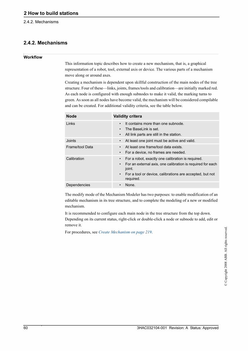
2 How to build stations2.4.2. Mechanisms
3HAC032104-001 Revision: A Status: Approved60
© C
opyr
ight
200
8 A
BB
. All
right
s res
erve
d.
2.4.2. Mechanisms
WorkflowThis information topic describes how to create a new mechanism, that is, a graphical representation of a robot, tool, external axis or device. The various parts of a mechanism move along or around axes.
Creating a mechanism is dependent upon skillful construction of the main nodes of the tree structure. Four of these—links, joints, frames/tools and calibration—are initially marked red. As each node is configured with enough subnodes to make it valid, the marking turns to green. As soon as all nodes have become valid, the mechanism will be considered compilable and can be created. For additional validity criteria, see the table below.
The modify mode of the Mechanism Modeler has two purposes: to enable modification of an editable mechanism in its tree structure, and to complete the modeling of a new or modified mechanism.
It is recommended to configure each main node in the tree structure from the top down. Depending on its current status, right-click or double-click a node or subnode to add, edit or remove it.
For procedures, see Create Mechanism on page 219.
Node Validity critera
Links • It contains more than one subnode.• The BaseLink is set.• All link parts are still in the station.
Joints • At least one joint must be active and valid.
Frame/tool Data • At least one frame/tool data exists.• For a device, no frames are needed.
Calibration • For a robot, exactly one calibration is required.• For an external axis, one calibration is required for each
joint.• For a tool or device, calibrations are accepted, but not
required.
Dependencies • None.

2 How to build stations2.4.3. Tools and tooldata
613HAC032104-001 Revision: A Status: Approved
© C
opyr
ight
200
8 A
BB
. All
right
s res
erve
d.
2.4.3. Tools and tooldata
OverviewTo simulate the robot tool, you need tooldata for the tool. If you import a predefined tool or if you create a tool using the Create Tool Wizard, the tooldata is automatically created; otherwise, you have to create the tooldata yourself.
The tooldata simplifies the programing work with respect to the different tools that may come in use. Defining separate sets of tooldata for different tools makes it possible to run the same robot program with different tools: only the new tooldata has to be defined. The tooldata contains the information required for moving and simulating the tool.
Two methods for manipulating tooldata in RobotStudio are as follows:
• Create or modify tooldata, see Tooldata on page 177 and Modify Tooldata on page 326, respectively. This will create all data necessary for programing, but there will be no visual tool during the simulation.
• Create tooldata for an existing geometry, Create Tool on page 224.
Creating and setting up a stationary toolThis information topic describes how to create a stationary tool. For information about creating a robot hold tool, see Create Tool on page 224.
Using a stationary tool, the robot holds and moves the work piece in relation to the tool. Thus, both the tooldata and the workobject must be set up correctly.
To create the tooldata for a stationary tool, follow these steps:
1. Import the geometry or library that represents the tool, see Import Geometry on page 172.
If you do not have the geometry or library at hand but know the position, you can skip this step. The tool will be programable, but not visible in the station.
2. Create the tooldata for the tool, see Tooldata on page 177.
Make sure to set the Robot holds tool option to false.
3. Create a workobject that is moved by the robot. see Workobject on page 176.
Make sure to set the Robot holds workobject option to true.
4. If you have a geometry or library component for the work piece, attach it to the robot, see Attach to on page 299.

2 How to build stations2.4.4. Setting the local origin of an object
3HAC032104-001 Revision: A Status: Approved62
© C
opyr
ight
200
8 A
BB
. All
right
s res
erve
d.
2.4.4. Setting the local origin of an object
OverviewEach object has a coordinate system of its own called local coordinate system in which the object dimensions are defined. When the object’s position is referred from other coordinate system, it is the origin of this coordinate system that is used.
With the Set Local Origin command you reposition the object’s local coordinate system, not the object itself.
For a procedure, see Set Local Origin on page 339.

2 How to build stations2.5.1. Placing objects
633HAC032104-001 Revision: A Status: Approved
© C
opyr
ight
200
8 A
BB
. All
right
s res
erve
d.
2.5 Placement
2.5.1. Placing objects
OverviewTo achieve the required layout of your station, you need to import or create objects, place them accordingly and, if applicable, attach them to other objects.
Placing objects means setting their position and rotation. If the objects are to be attached to robots or other mechanisms, they will be placed at their attachment point automatically.
The following table describes the actions relating to placement:
Actions Description
Placing an object To place an object is to put the object in the required position in the station, see Place on page 330 and Set Position on page 341.
Rotating an object The objects in the station can be rotated to achieve the required layout, see Rotate on page 335.
Measuring distance or amgles
The measurement functions calculates distances, angles and diameters between points you select from the graphics window.When using measurements, results and instructions on how to proceed are displayed in the Output window, see The Measure Group on page 218.
Creating a component group
A component group groups related object in the browser, see Component Group on page 198.
Attaching or detaching an object
Objects that are to be used by the robots in any way, such as tools, need to be attached to the robot, see Attach to on page 299 and Detach on page 307.
Jogging a robot Robots can be placed by jogging. The robot axes can also be postioned by jogging, see Jogging mechanisms on page 70.
Modifying the task frame Modifying the task frame repositions a controller and all its robots and equipment in the station.By default the controller world and the station world coordinate system coincide. This is convenient when building a station with one single controller. For a procedure, see Set Task Frames on page 269.However, when you have several controllers in one station, or need to reposition a controller in an existing station, you need to modify the System Configuration on page 270.
Modifying the baseframe position
Modifying the baseframe position sets an offset between the controller’s world coordinate system and the baseframe of the mechanical unit.This is necessary when having several mechanical units belonging to one controller, for example, several robots in MultiMove systems or when using positioner external axes. For a procedure, see System Configuration on page 270.

2 How to build stations2.5.2. Placing external axes
3HAC032104-001 Revision: A Status: Approved64
© C
opyr
ight
200
8 A
BB
. All
right
s res
erve
d.
2.5.2. Placing external axes
OverviewWhen starting a system with a track or positioner external axis in a RobotStudio station, you have to set up the system to load a model for the track or positioner and get the motions to work properly.
PrerequisitesThe system shall be created with support for track or positioner external axes, see A system with support for one robot and one track external axis and A system with support for one robot and one positioner external axis on page 140, respectively.
Attaching the robot to the trackTo attach the robot to the track, follow these steps:
1. In the Layout browser, drag the robot icon and drop it on the track icon.
2. On the question Should the robot be coordinated with the track?, answer Yes to be able to coordinate the track’s position with that of the robot in robot programs. To program the track and the robot independently, answer No.
3. When asked if you want to restart the system, answer Yes.
The track is now added to the system and ready to be programmed, see Programing external axes on page 95 for more information on how to program the track.
CAUTION!If the system is cold started , the setup is deleted and the procedures described here must be performed again.
Placing the positioner in the stationTo place the positioner in the station, follow these steps:
1. Move the positioner to the desired position using any of the ordinary functions for placing and moving objects, see Placing objects on page 63.
2. Modify the baseframe position of each mechanical unit of the positioner except the INTERCH unit, if it exists. When asked if you want to restart the system, answer Yes.
See Baseframe position for detailed instruction.
After the restart the system is updated with the positioner’s new location. Continue attaching fixtures and workobjects to the positioner.
Continues on next page

2 How to build stations2.5.2. Placing external axes
653HAC032104-001 Revision: A Status: Approved
© C
opyr
ight
200
8 A
BB
. All
right
s res
erve
d.
Attaching objects to the positionerTo program robot motions on an object that is held by the positioner, the targets must be created in a workobject that is attached to the positioner. For a complete visual simulation, CAD models that are moved by the positioner should also be attached. To attach the objects, follow these steps:
1. Import the models of the fixture and the work piece if you do not have them in the station already, see Importing a station component on page 53.
2. Attach the fixture to the positioner, see Attaching and detaching objects on page 43. When asked whether to keep the current position, answer No.
If the positioner has several stations, you will be asked which one to attach the object to.
3. Attach the work piece to the fixture. When asked whether to keep the current position, answer No.
4. Attach the workobject in which you will program the work piece to either the fixture, the work piece or the positioner. If you have defined calibration positions on either the work piece or the fixture, it is a good practice to use that object. When asked whether to keep the current position, answer No.
The positioner is now set up and ready to be programed, see Programing external axes on page 95 for more information.
TIP!If the positioner is of an interchangeable type with several stations, you can either attach individual fixtures, work pieces and workobjects to each station flange, or you can use one set of objects that you attach and detach to the different flanges by events.
CAUTION!If the system is cold started, the setup is deleted and the procedures described here must be performed again.
Continued

2 How to build stations2.5.2. Placing external axes
3HAC032104-001 Revision: A Status: Approved66
© C
opyr
ight
200
8 A
BB
. All
right
s res
erve
d.

3 How to program robots2.5.2. Placing external axes
673HAC032104-001 Revision: A Status: Approved
© C
opyr
ight
200
8 A
BB
. All
right
s res
erve
d.
3 How to program robots

3 How to program robots3.1. Workflow for programing a robot
3HAC032104-001 Revision: A Status: Approved68
© C
opyr
ight
200
8 A
BB
. All
right
s res
erve
d.
3.1. Workflow for programing a robot
OverviewIn most cases, going through the workflow from start to finish is recommended, even if it possible to work in other sequences as well.
Synchronizing will save and load text files containing RAPID modules, and create RAPID programs from your station.
PrerequisitesBefore creating a program for your robot, you should set up the station, including robots, work pieces and fixtures, in which your robot will work.
Programing a robotThe table below describes the workflow for programing a robot to perform the task you require.
Task Description
Create targets and paths Create the targets and paths the robot requires to perform the work tasks.To create targets and paths, do one of the following:
• Create a curve to match your required shape. Then use the Create path from curve command to generate a path, complete with targets, along the shape you have created. See Curve on page 206 and Path from Curve on page 183.
• Create targets at the requested positions, then create a path and insert the created targets into it. See Create Target on page 179, Teach Target on page 178 and Empty Path on page 182.
Check the target orienta-tions
Make sure that the targets are oriented in the most efficient way for the tasks to be performed. If not, reorient the targets until you are satisfied. See Orientations on page 77.
Check reachability Check that the robot and tool reach all targets in the path. See Testing positions and motions on page 86.
Synchronize the program to the virtual controller
Generates RAPID code from the RobotStudio items and enables the program to be simulated.
Perform text-based editing
If you need to edit the instructions or data created by RobotStu-dio, you can start the Program Editor. See Using the RAPID editor on page 99.
Collision detection Check that the robot or tool does not collide with the surrounding equipment or the fixtures. If it does, adjust the placements or orientations until no collisions occur. See Detecting collisions on page 105.
Test the program Test the program by moving along the paths. See Testing positions and motions on page 86.

3 How to program robots3.2. Workobjects
693HAC032104-001 Revision: A Status: Approved
© C
opyr
ight
200
8 A
BB
. All
right
s res
erve
d.
3.2. Workobjects
Creating a workobjectA workobject is a coordinate system used to describe the position of a work piece. The workobject consists of two frames: a user frame and an object frame. All programed positions will be related to the object frame, which is related to the user frame, which is related to the world coordinate system.
xx0500001519
For a procedure, see Workobject on page 176.
Modifying a workobjectFor a procedure, see Modify Workobject on page 327.
Converting a frame to a workobjectYou can create a new workobject from an existing frame. The converted workobject gets the same name and position as the selected frame.
For a procedure, see Convert Frame to Workobject on page 304.
Creating a frame by pointsYou can create a frame by specfiying points on the axes of the coordinate system and letting RobotStudio calulate the placement and orientation of the frame’s origin.
For a procedure, see Frame from Three Points on page 174.

3 How to program robots3.3. Jogging mechanisms
3HAC032104-001 Revision: A Status: Approved70
© C
opyr
ight
200
8 A
BB
. All
right
s res
erve
d.
3.3. Jogging mechanisms
Jogging a robotTo check if the robot can reach all positions on the work piece, you can jog the TCP or the joints of the robot, either with the freehand commands of through dialog boxes. Jogging the robot close to its boudaries is best done with the latter method.
PrerequisitesTo jog the TCP of a robot, the robot’s VC must be running.
Jogging several mechanisms
To Procedure
Jog the joints of a robot For freehand, see Jog Joint on page 193. For a dialog box, see Mechanism Joint Jog on page 315.
Jog the TCP of a robot For freehand, see Jog Linear on page 194. For a dialog box, see Mechanism Linear Jog on page 316.
Function Description
Mutlirobot jog When using multirobot jog, all selected mechanisms will follow the TCP of the one being jogged. Multirobot jog is available for all kinds of jogging.See MultiRobot Jog on page 195.
Jogging with locked TCP When jogging a mechanism that moves a robot (like a track external axis) with locked TCP, the robot will reposition so that the position of the TCP does not change, even though its baseframe is moved.When jogging an external axis that moves the work object with locked TCP, the robot will reposition so that its TCP follows the work object in the same way as when using multirobot jog.Locked TCP is available when jogging a mechanism that belongs to the same task as a robot.See Mechanism Joint Jog on page 315.

3 How to program robots3.4. Targets
713HAC032104-001 Revision: A Status: Approved
© C
opyr
ight
200
8 A
BB
. All
right
s res
erve
d.
3.4. Targets
Creating a targetYou can create a new target manually either by entering the position for the target in the Create Target dialog box or by clicking in the graphics window.
The target will be created in the active workobject.
For a procedure, see Create Target on page 179.
Creating a jointtargetA jointtarget is a specification of the position for the robot axes.
For a procedure, see Create Jointtarget on page 181.
Teaching targetsYou can create a new target by jogging the robot and teaching a target at the active TCP. Taught targets will be created with the axis configuration used when jogged to the target.
The target will be created in the active workobject.
For a procedure, see Teach Target on page 178.
Modifying a target positionBy using the modify position command you can modify the position and rotation of a target.
For procedures, see Set Position on page 341 and Rotate on page 335, respectively.
Modifying a target with ModPosThe position of an existing target can be modified by jogging the robot to a new, preferred position. By selecting a move instruction for the target in a path, the ModPos command can be used to move the target to the TCP of the active tool.
When ModPos is executed, the target, referenced to by the move instruction, will be updated with the following information:
• position and orientation corresponding to the TCP of the active tool
• the current configuration of the active robot
• the current position and orientation values of all active external axes for the active robot
NOTE: To jog a robot linearly, a virtual controller must be running for that robot. For detailed information, see Starting a VC on page 50.
Continues on next page

3 How to program robots3.4. Targets
3HAC032104-001 Revision: A Status: Approved72
© C
opyr
ight
200
8 A
BB
. All
right
s res
erve
d.
Renaming targetsWith this command you can change the name of several targets at once. You can either rename targets individually, or you can rename all targets in one or several paths at once.
The new target names will consist of an optional prefix, an incremental number and an optional suffix.
For a precedure, see Rename Targets on page 333.
When renaming targets, make sure that the new targets conform to the naming rules. The target names must:
• start with an alphabetical character in the ISO 8859-1 encoding (that is, an ordinary letter from the English alphabet)
• be shorter than 16 characters
• not be empty strings
• not contain any characters illegal in RAPID. See the RAPID reference manual for details.
Removing unused targetsIf deleting or changing paths or move instructions during programing, you might end up with large numbers of targets that are no longer used in any instructions. To make the workobjects and their targets easier to grasp, you can delete all unused targets.
For a procedure, see Remove Unused Targets on page 332.
Continued

3 How to program robots3.5. Paths
733HAC032104-001 Revision: A Status: Approved
© C
opyr
ight
200
8 A
BB
. All
right
s res
erve
d.
3.5. Paths
Creating an empty pathA path is a sequence of targets with move instructions that the robot follows. An empty path will be created in the active task.
For a procedure, see Empty Path on page 182.
Creating a path from curveIf the work piece has curves or contours that correspond to the path to be created, you can create the paths automatically. The create path from curve command generates paths, complete with targets and instructions along existing curves.
The path will be created in the active task.
The orientation of the targets that will be created will be according to the settings of the approach/travel vectors in the Options dialog box.
To create a path from a curve, the curve must have first been created in the station.
For a procedure, see Path from Curve on page 183.
Setting robot axis configuration for pathsThe robot axis configuration specifies the position of the axes as the robot moves from target to target, when multiple solutions are possible. This is necessary for executing move instructions using configuration monitoring.
Taught targets have validated configurations, but targets created in any other way do not. Also, targets that are repositioned lose their configuration. In RobotStudio, targets without a valid configuration are marked with a yellow warning symbol. See Robot axis configurations on page 24 for more information about configurations.
To set a configuration for all targets in a path, see Auto-Configuration on page 300.
To set a configuration for a single target, see Configurations on page 302.
Reversing pathsThe reverse path commands change the sequence of targets in the path so that the robot moves from the last target to the first. When reversing paths, you can reverse either the target sequence alone or the entire motion process.
For procedures, see Reverse Path on page 334.
Continues on next page

3 How to program robots3.5. Paths
3HAC032104-001 Revision: A Status: Approved74
© C
opyr
ight
200
8 A
BB
. All
right
s res
erve
d.
NOTE!When reversing paths, the original paths are deleted. If you want to keep them, make copies before reversal.
NOTE!When reversing paths, only move instructions are handled. Action instructions, if any exist, have to be inserted manually after the reversal.
Rotating pathsWith the rotate path command you can rotate complete paths and move the targets used by the paths accordingly. When rotating paths, the included targets will lose their axis configurations, if any have been assigned.
A frame or target must exist at the position to rotate around before starting the rotate path command.
For a procedure, see Rotate Path on page 336.
Translating a pathThe translate path function moves a path and all included targets.
For a procedure, see Translate Path on page 343.
Compensating paths for tool radiusYou can offset a path so that it compensates for the radius of a rotating tool. Since the targets in the path are moved, they will lose their axis configurations, if any have been assigned.
For a procedure, see Tool Compensation on page 342.
Continued
Continues on next page

3 How to program robots3.5. Paths
753HAC032104-001 Revision: A Status: Approved
© C
opyr
ight
200
8 A
BB
. All
right
s res
erve
d.
Interpolating a pathThe interpolate functions reorient the targets in a path so that the difference in orientation between the start and end targets is distributed evenly among the targets in between. The interpolation can be either linear or absolute.
Linear interpolation distributes the difference in orientation evenly, based on the targets’ positions along the length of the path.
Absolute interpolation distributes the difference in orientation evenly, based on the targets’ sequence in the path.
Below are examples of the difference bewteen linear and absolute interpolation.
The interpolate functions reorient the targets in a path so that the difference in orientation between the start and end targets is distributed evenly among the targets in between. The interpolation can be either linear or absolute.
For a procedure, see Interpolate Path on page 311.
No interpolationThis is the path before any interpolation. Note that the last target is oriented differently than the others.
xx0500002029
Linear interpolationThis is the same path after linear interpolation.
xx0500002030
Note that the targets are oriented based on their placement relative to the start and end targets.
If a target were moved and you reran the linear interpolation, it would be reoriented according to its new position.
If new targets were inserted between the existing ones and you reran the linear interpolation, it would not affect the orientation of the existing targets.
Continued
Continues on next page

3 How to program robots3.5. Paths
3HAC032104-001 Revision: A Status: Approved76
© C
opyr
ight
200
8 A
BB
. All
right
s res
erve
d.
Absolute interpolationThis is the same path after absolute interpolation
xx0500002031
Note that the targets are orientated based on their sequence in the path: each target has been reoriented equally, regardless of its place.
If a target were moved and you reran the absolute interpolation, it would not affect the orientation.
If new targets were inserted between the existing ones and you reran the absolute interpolation, it would change the orientation of all targets.
Mirroring a pathThe mirror path function mirrors all motions instructions and their targets to a new path.
For a procedure, see Mirror Path on page 317.
Continued

3 How to program robots3.6. Orientations
773HAC032104-001 Revision: A Status: Approved
© C
opyr
ight
200
8 A
BB
. All
right
s res
erve
d.
3.6. Orientations
OverviewThis is an overview of the tools for automating the modification of target orientations.
When creating paths from curves in RobotStudio, the orientation of the targets depends on the characteristics of the curves and the surrounding surfaces. Below is an example of a path with unordered target orientations and examples of how the different tools have affected the targets.
Unordered orientationsIn the path below, the target orientations are unordered. The function View tool at target has been used for illustrating how the targets point in different directions.
xx0500001864
Effect of target normal to surfaceIn the picture below, the targets, which previously were orientated randomly, have been set normal to the flat round surface at the right side of the path. Note how the targets’ Z axis has been orientated normal to the surface; the targets have not been rotated in the other directions.
xx0500001865
Continues on next page

3 How to program robots3.6. Orientations
3HAC032104-001 Revision: A Status: Approved78
© C
opyr
ight
200
8 A
BB
. All
right
s res
erve
d.
Setting a target normal to surfaceTo set a target orientation normal to a surface is to make it perpendicular to the surface. The target can be oriented normal to the surface in two different ways:
• The entire surface can be used as a reference for the normal. The target will be oriented as the normal to the closest point at the surface. The entire surface is the default surface reference.
• A specific point on the surface can be used as the reference for the normal. The target will be orientated as the normal to this point, regardless of whether the normal to the closest point at the surface has another orientation.
Objects imported without geometry (for example, .jt files) can only refer to specific points on the surface.
For a procedure, see Set Normal to Surface on page 340.
Effect of align target orientationIn the picture below, the targets, which were previously orientated with the Z axis normal to the surface but with the X and Y axes orientated randomly, have been organized by aligning the targets’ orientation around the X axis with the Z axis locked. One of the targets in the path has been used as reference.
xx0500001866
Aligning a target orientationWith the align target orientation command you align the rotation of selected targets around one axis without changing the rotation around the others.
For a procedure, see Align Target Orientation on page 298.
Continued
Continues on next page

3 How to program robots3.6. Orientations
793HAC032104-001 Revision: A Status: Approved
© C
opyr
ight
200
8 A
BB
. All
right
s res
erve
d.
TIP!You can also align ordinary frames in the same way.
Effects of copy and apply orientationIn the picture below, the targets, which were previously oriented randomly, have been organized by copying the exact orientation of one target to all the others. This is a quick way to fix workable orientations for processes where variations in approach, travel, or spin directions either do not matter or are not affected, due to the shape of the work piece.
xx0500001867
Copying and applying an orientation for objectsTo transfer an orientation from one object to another is an easy way to align different frames for simplifying the programing of the robot. Target orientations may also be copied.
For procedures, see Copy / Apply Orientation on page 306.
Continued

3 How to program robots3.7. RAPID Instructions
3HAC032104-001 Revision: A Status: Approved80
© C
opyr
ight
200
8 A
BB
. All
right
s res
erve
d.
3.7. RAPID Instructions
Move and action instructionsFor RAPID programing, RobotStudio’s main advantage is in the area of motion programing.
A move instruction is an instruction for the robot to move to a specified target in a specified manner. With RobotStudio, you can create move instructions in three ways:
In addition to move instructions, you can also create and insert action instructions from RobotStudio. An action instruction is an instruction other than a move instruction that can, for example, set parameters, or activate or deactivate equipment and functions. The action instructions available in RobotStudio are limited to those commonly used for affecting the robot’s motions. For inserting other action instructions or another kind of RAPID code in the program, use the Program Editor. For a procedure, see Action Instruction on page 188.
The table below lists the action instructions that can be created. For details, see the RAPID Reference Manual.
Method Description
Create a move instruction based on an existing target
Creates move instructions based on one or several targets selected in the Paths&Targets browser. For a procedure, see Add to Path on page 296.
Create a move instruction and a corresponding target
Creates a move instruction and a corresponding target at once. The position of the target can either be selected from the graphics window or typed numerically. For a procedure, see Move Instruction on page 187.
Teach a move instruction Teaching a move instruction creates a move instruction and a corresponding target at the robot’s current position. Teaching a move instruction also stores the current configuration with the target. For a procedure, see Teach Instruction on page 186.
Action instruction Description
ConfL On/Off ConfL specifies whether to monitor the robot’s configurations during linear movements. When ConfL is set to Off, the robot may use another configuration than the programed one for reaching the target during program execution.
ConfJ On/Off ConfJ specifies whether to monitor the robot’s configurations during joint movements. When ConfJ is set to Off, the robot may use another configuration than the programed one for reaching the target during program execution.
Actunit UnitName Actunit activates the mechanical unit specified by UnitName.
DeactUnit UnitName Deactunit deactivates the mechanical unit specified by UnitName.
Continues on next page

3 How to program robots3.7. RAPID Instructions
813HAC032104-001 Revision: A Status: Approved
© C
opyr
ight
200
8 A
BB
. All
right
s res
erve
d.
Modifying an instructionMost instructions have arguments that specify how the instruction shall be carried out. For example, the MoveL instruction has arguments that specify the speed and accuracy with which the robot moves to the target.
For a procedure, see Modify Instruction on page 324.
NOTE!Some arguments are read from the virtual controller. If the virtual controller has not been started, only the arguments stored in the station can be modified.
Converting to move circularTo create a circular motion to an instruction target, you must convert the motion type to circular motion (that is, MoveC in RAPID).
A circular motion is defined by two motion instructions, where the first is the via-point and the second contains the end point of the circular motion.
The circular motion can only be used for open circular arcs, not for closed circles. To create a path for a closed circle, use two circular motions.
For a procedure, see Convert to Move Circular on page 305.
Creating RAPID instructions for setting I/O signalsFor controlling I/O signals in the robot program, you use RAPID commands that set the signals. These require that you first create instruction templates for the instructions that set the signals. See the RAPID reference manual for details about the instructions that control I/O signals.
To add RAPID instructions that set I/O signals, follow these steps:
1. Synchronize the system in which you want to add the instructions to the virtual controller, see Synchronization on page 98.
2. In programing mode, select the module for editing, right-click it and then click Edit program.
3. In the program editor, add the instructions for setting the signals.
4. When you are done adding instructions, synchronize the task and paths from the Virtual Controller back to the station.
Continued
Continues on next page

3 How to program robots3.7. RAPID Instructions
3HAC032104-001 Revision: A Status: Approved82
© C
opyr
ight
200
8 A
BB
. All
right
s res
erve
d.
Using cross-connections and groups for setting I/O signalsYou can also create cross-connections and signal groups, which make one signal set the value of several other signals. See the System parameters reference manual for details about cross-connections and groups.
To make one signal set several others, follow these steps:
1. Request write access, and then open the configuration topic I/O in the configuration editor. Add configure instances for the cross-connections and groups to create.
Instruction templatesInstruction templates contain predefined sets of argument values that are applied to the instructions you create using the template. You can create templates for all instructions in the system running on the virtual controller. To see which instructions are available and what their arguments do, see the RAPID reference manual for your RobotWare version and the reference sections in manuals for software options, if you have any installed on the system.
Move instruction templates are always part of process templates. The process templates contain one instruction template for each type of move instruction that might be used by the process.
The process templates are instances of process definitions, which define the types of move instructions (move instruction definitions) that might be used by the process.
To create new move instruction templates, start by creating a new process template for a process that uses the type move instructions you want to create templates for. If such a process does not exist, you first have to create a new process definition.
If no move instruction definition for the type of instruction you want to create a template for exists, you must create it first.
When creating instruction descriptions, the virtual controller must be running, since the available instruction types are read from the system.
Method Description
Creating a process template with move instruction templates on page 83
Move instructions are always related to processes.
Creating a move instruction description on page 83
To create templates for other instructions than the one that already exists in the tree view, you first have to create an instruction description that defines the arguments that belong to the instruction.
Editing an instruction template on page 84
XXX
Creating a process definition on page 84
XXX
Creating an action instruction template on page 84
XXX
Creating an action instruction description on page 85
To create templates for other instructions than the one that already exists in the tree view, you first have to create an instruction description that defines the arguments that belong to the instruction.
Continued
Continues on next page

3 How to program robots3.7. RAPID Instructions
833HAC032104-001 Revision: A Status: Approved
© C
opyr
ight
200
8 A
BB
. All
right
s res
erve
d.
Templates can be imported and exported on four levels: tasks, move instruction descriptions, action instruction descriptions and process definitions. The default directory for imported and exported template files is My Documents/RobotStudio. Simply choosing another directory will then make that directory default. The default file format is .xml.
The validation procedure checks for duplicate names, incomplete process definitions and virtual controller equality. It is performed automatically, after a template file has been imported or a node renamed or deleted.
For procedures, see Instruction Template Manager on page 189.
Creating a process template with move instruction templates1. On the Home tab, from the active Task list, select the task for the robot for which you
want to create the instruction template.
2. On the Create menu, click Instruction Template Manager. This opens the Instruction templates page in the work space.
3. In the Instruction Templates tree to the left, make sure there are move instruction definitions for the types of move instructions you want to create templates for. If not, follow the procedure in Creating a move instruction description on page 83 for creating them.
4. Make sure there is a process definition that uses the types of move instructions you want to create templates for. If not, follow the procedure in Creating a process definition on page 84 for creating it.
5. Right-click the process definition for which you want to create a new templates and click Create Process Definition.
6. In the Create Process Definition dialog box, enter a name, with characters from ASCII set, for the new template and click Create. A new process template node with a set of move instruction templates is now created.
7. Select each new template one at a time, and in the arguments grid to the right of the tree view, set the argument values that shall be applied when you create new instructions based on the template. Finish for each template by clicking Apply changes at the bottom of the grid.
For details about available arguments and what they do, see the RAPID reference manual for ordinary RAPID instructions and the option manual for software option instructions.
Creating a move instruction descriptionTo create the instruction description, follow these steps:
1. Right-click the Move Instructions node and click Create Move Instruction Description. This opens the Create Move Instruction Description dialog box.
2. In the Controller Description list, select the instruction you want to make a description for. All action instructions installed on the controller, both through RobotWare and software options, are available.
3. In the Motion type list, select the motion type for the instruction.
4. Optionally, in the Information text box, enter a comment to the instruction.
5. Click Create. The instruction description appears in the tree view and its settings are displayed in the grid.
Continued
Continues on next page

3 How to program robots3.7. RAPID Instructions
3HAC032104-001 Revision: A Status: Approved84
© C
opyr
ight
200
8 A
BB
. All
right
s res
erve
d.
6. In the instruction grid, set the point type values. If necessary, also change the other settings.
7. After changing the settings, click Apply Changes in the bottom of the grid view.
Editing an instruction templateTo edit an instruction template, follow these steps:
1. In the active task list, select the task for the robot for which you want to edit the instruction template.
2. On the Create menu, click Instruction Template Manager. This opens the Instruction templates page in the work space.
3. In the Instruction Templates tree to the left, browse to and select the template to edit.
4. In the arguments grid to the right of the tree view, set the argument values that shall be applied when you create new instructions based on the template. Finish by clicking Apply changes at the bottom of the grid.
For details about available arguments and what they do, see the RAPID reference manual for ordinary RAPID instructions and the option manual for software option instructions.
Creating a process definitionTo create a process definition, follow these steps:
1. Make sure there are move instruction definitions for the types of move instructions you want to create templates for. If not, follow the procedure above for creating them.
2. Right-click the Process definitions node and click Create Process Definition. This opens the Create Process Description dialog box.
3. In the Create Process Definitions dialog box, enter a name for the process definition, a name for its first process template and then select the move instruction types to use. Finish by clicking Create.
Creating an action instruction templateTo create a template for an action instruction, follow these steps:
1. In the active task list, select the task for the robot for which you want to create the instruction template.
2. On the Home menu, click Instruction Template Manager.
3. In the Instruction Templates tree to the left, right-click the instruction description (corresponding to the instructions as described in the RAPID reference manual) for which you want to create a new template and click Create Action instruction Template.
If the instruction description does not exist in the tree, create it by following the procedure described in Creating an action instruction description on page 85.
Continued
Continues on next page

3 How to program robots3.7. RAPID Instructions
853HAC032104-001 Revision: A Status: Approved
© C
opyr
ight
200
8 A
BB
. All
right
s res
erve
d.
4. In the Create Action Instruction Template dialog box, enter a name for the new template and click Create. The new template is now created under the instruction description node it belongs to.
5. Select the new template and in the arguments grid to the right of the tree view, set the argument values that shall be applied when you create new instructions based on the template. Finish by clicking Apply changes at the bottom of the grid.
For details about available arguments and what they do, see the RAPID reference manual for ordinary RAPID instructions and the option manual for software option instructions.
Creating an action instruction descriptionTo create the instruction description, follow these steps:
1. Right-click the Action Instructions node and click Create Action Instruction Description. This opens the Create Instruction Description dialog box.
2. In the Controller Description list, select the instruction you want to make a description for. All action instructions installed on the controller, both through RobotWare and software options, are available.
3. Optionally, in the Information text box, enter a comment to the instruction.
4. Click Create. The instruction description appears in the tree view, and its settings are displayed in the grid.
After changing the settings (if necessary), click Apply Changes in the bottom of the grid view.
5. Continue with creating templates for the instruction description, as described in Creating an action instruction template on page 84.
Continued

3 How to program robots3.8. Testing positions and motions
3HAC032104-001 Revision: A Status: Approved86
© C
opyr
ight
200
8 A
BB
. All
right
s res
erve
d.
3.8. Testing positions and motions
OverviewRobotStudio has several functions for testing how robots reach and move to targets. They are useful both for finding the optimal layout when building a station and during programing.
Below are brief descriptions of the functions for testing reachability and motions.
Checking reachabilityThe check reachability function displays whether the robot can reach selected targets and motion instructions by changing the frames’ colors in the graphic view. Reachable frames are colored green, unreachable red, and frames with reachable positions but not with current orientation are colored yellow.
The reachability check is useful when building the station, since the reachability of several targets are displayed at once. For a procedure, see Check Reachability on page 301.
Jumping to targetJump to target tests whether the robot can reach a specific position. This is useful when building the station: by creating targets at critical positions on the work piece and jumping the robot to them, you get an early indication of whether the items are positioned correctly or not. For a procedure, see Jump to Target on page 313.
Viewing a robot at targetWhen View robot at target is activated, the robot is automatically positioned with the tool at the target when one is selected. If several robot axis configurations are possible for reaching the target, the robot will use the one nearest the configuration it had before jumping to the target. For a procedure, see View Robot at Target on page 344.
Viewing tool at targetView tool at target displays the tool at target, without checking that the robot can reach it. This test is useful both when building the station and when programing the robot, since the orientation of targets both affects the reachability and the process performance. For a procedure, see View Tool at Target on page 345.
Executing move instructionsExecute move instruction tests if the robot can reach a specific position with the programed motion properties. This is useful for testing motions during programing. For detailed information, see Execute Move Instruction on page 308.
Moving along pathMove along path executes all move instructions in a path. It is thereby a more complete test than Execute move instructions, but not as complete as a full simulation, since it ignores RAPID code that is not move instructions. For a procedure, see Move Along Path on page 328.
Continues on next page

3 How to program robots3.8. Testing positions and motions
873HAC032104-001 Revision: A Status: Approved
© C
opyr
ight
200
8 A
BB
. All
right
s res
erve
d.
Moving to a poseMoving to a pose moves a mechanism to a predefined joint value at a predefined time without using the Virtual Controller. This is useful when movement of the external equipment (such as a clamp or conveyer) must be simulated. For a procedure, see Move to Pose on page 329.
Simulating programsSimulating programs involves running a program on the virtual controller as it is run on a real controller. It is the most complete test whereby you can see how the robot interacts with external equipment through events and I/O signals. For a procedure, see Simulation Setup on page 229.
Improving the reachabilityIf the robot cannot reach the target, or if you are not satisfied with the motions, try the following for improving the reachability:
Set ConfL or ConfJ to Off for enabling the robot to use new configurations for reaching the target.
Change the orientation of the target.
Change the position of either the robot or the work piece.
Use a system with a track external axis for increasing the robot’s range.
Use a system with a positioner external axis for enabling different work piece positions for different targets.
Continued

3 How to program robots3.9.1. About programing MultiMove
3HAC032104-001 Revision: A Status: Approved88
© C
opyr
ight
200
8 A
BB
. All
right
s res
erve
d.
3.9 Programing MultiMove systems
3.9.1. About programing MultiMove
About MultiMoveThe MultiMove functions helps you create and optimize programs for MultiMove systems where one robot or positioner holds the work piece and other robots operate on it. Below is an outline of the main workflow for programing MultiMove systems with RobotStudio, with references to detailed instructions further down in the section.
PrerequisitesFor using the MultiMove functions you must first have the following:
• A virtual controller running a MultiMove system started in RobotStudio, see A MultiMove system with two coordinated robots on page 138 for an example.
• All coordinate systems and tools used by the system.
• The paths along which the tool shall move. The paths must be created in a workobject that belongs to a tool robot and is attached to the work piece robot. A wizard will guide you through attaching the workobjects if this has not been done before starting the MultiMove functions.
For detailed information about MultiMove in RobotWare systems and RAPID programs, see the MultiMove application manual.
Normal workflowThis is the typical workflow for creating MutliMove programs using the MultiMove function:
Action Description
Setting up the MultiMove Select the robots and paths to use in the program, see Setting up the MultiMove on page 90.
Testing the MultiMove Execute the motion instructions along the paths, see Testing the MultiMove on page 91.
Tuning the motion behavior Tune motion behavior, such as tolerances and constraints for TCP motions, see Tuning the motion behavior on page 92.
Creating the program Generate the tasks for the robots, see Creating paths on page 94.
Continues on next page

3 How to program robots3.9.1. About programing MultiMove
893HAC032104-001 Revision: A Status: Approved
© C
opyr
ight
200
8 A
BB
. All
right
s res
erve
d.
Additional actionsIn addition to using the functions that calculate and create optimized MulitMove paths, you can program MulitMove manaully using a combination of the ordinary programing tools in RobotStudio and a set of tools specific for MultiMove programing.
The main actions for programing MulitMove manually are outlined below. Not all actions might be necessary, but the order in which they shall be carried out depends on the contents of the station and your goals.
Action Description
Creating Tasklists and Syncidents
This data specifies the tasks and paths that shall be syn-chronized with each other. See The Create Tasklist tool on page 249 and The Create Syncident tool on page 249, respectively.
Adding and updating ID arguments to the instructions to synchronize
To add IDs to the intructions, you can use one of the following methods:Using The Recalculate ID tool on page 248 to add and update IDs for instructions in paths that already are syn-chronized.Using The Convert path to MultiMove path tool on page 249 to add IDs to instructions in paths that have not yet been synchronized.
Adding and adjusting Sync instructions to the paths.
Add SyncMoveon/Off or WaitSyncTask instructions to the paths to synchronize and set their tasklist and Syncident parameters. See Creating an action instruction on page 188.
Teaching MultiMove instructions It is also possible to jog all robots to the desired positions and then teach instructions to new synchronized paths. See MultiTeach tab on page 245.
Continued
3 How to program robots3.9.2. Setting up the MultiMove
3HAC032104-001 Revision: A Status: Approved90
© C
opyr
ight
200
8 A
BB
. All
right
s res
erve
d.
3.9.2. Setting up the MultiMove
Selecting robots and pathsThis procedure is for selecting the robots and paths in the station that shall be used for the MutliMove program. All robots for the MultiMove program must belong to the same system.
1. On the Simulation tab, click MultiMove. Click the Setup tab below the MutliMove work area.
2. In the work area, click the System config bar for expanding the system config section.
3. In the Select System box, select the system that contains the robots to program.
The robots of the selected system are now displayed in the System grid below the Select system box.
4. For each robot that shall be used in the program, select the check box in the Enable column.
5. For each robot that shall be used in the program, specify whether it carries the tool or the work piece using the options in the Carrier column.
6. In the work area, click the Path config bar for expanding the path config section.
7. Select the Enable check box for the tool robot and click the expand button. This displays the paths of the robot.
8. Select the order of the paths to execute by specifying them in right order using Path name column.
9. For each path that shall be included in the program, select the check box in the Enable column.
10. When you have set up the robots and paths, continue testing the Multimove and then tune the motion properties, if necessary.

3 How to program robots3.9.3. Testing the MultiMove
913HAC032104-001 Revision: A Status: Approved
© C
opyr
ight
200
8 A
BB
. All
right
s res
erve
d.
3.9.3. Testing the MultiMove
OverviewTesting the MultiMove executes the motion instructions along the paths according to the current settings on the setup and motions properties pages.
Testing PathsThis procedure is for setting the robots start position and testing the resulting movements along the path sequence.
1. Jog the robots to what seems to be a good start position.
2. On the Simulation tab, click MultiMove. Click the Test tab at the bottom of the MultiMove work area for displaying the test area.
3. Optionally, select the Stop at end check box to make the simulation stop after moving along the paths. Clearing this check box makes the simulation continue in a loop until you click Pause.
4. Click Play to simulate the motions along the paths based on the current start position.
If you are satisfied with the motions, continue generating multimove paths. If the simulation cannot complete or if you are not satisfied with the motions, pause the simulation and perform any of the actions below to adjust the motions:
Action Description
Examine the robots’ positions for critical targets.
Click Pause and then use the arrow buttons to move to one target a time.
Jog the robots to new start positions.
New start positions might result in changed motions, since the robots will use different configurations. In most cases, positions near the robots’ joint limits shall be avoided.
Go to the Motion Behavior tab and remove constraints.
The default setting for the motion properties is no constraints. If this has been changed, constraints might exist that limit motions more than necessary.

3 How to program robots3.9.4. Tuning the motion behavior
3HAC032104-001 Revision: A Status: Approved92
© C
opyr
ight
200
8 A
BB
. All
right
s res
erve
d.
3.9.4. Tuning the motion behavior
OverviewTuning the motion behavior means to set up rules for the robot’s motions, for example, constraints on the position or orientation of the tool. Generally, the MultiMove program will obtain the smoothest motions with the fastest cycle and process times with as few constraints as possible.
For procedures, see Motion Behavior tab on page 242.
Modifying the joint influencesThe joint influence controls the balance of how much the robots will use their joints. Decreasing the weight value for one axis will restrict the motion for this axis, while increasing it will promote motion on this axis relative to alternative axes.
1. On the Simulation tab, click the Motion Behavior tab.
2. Expand the Joint Influence group by clicking its title bar.
3. In the Select Robot box, select the robot whose joint influence you want to modify.
The weight values for the robot axes are now displayed in the grid.
4. For each axis whose motion you want to restric or promote, adjust the Weight value. A lower value restricts, and a higher value promotes, motions on that axis.
Modifying the TCP constraintsThe joint influence controls the balance of how much the robots will use their joints. Decreasing the weight value for one axis will restrict the motion for this axis, while increasing it will promote motion on this axis relative to alternative axes.
1. On the Simulation tab, click the Motion Behavior tab.
2. Expand the TCP Constraints group by clicking its title bar.
The directions and rotations in which you can constrain the TCP’s motion are now displayed in the grid
3. For each pose you want to constrain, select the Enable check box and specify the constraint values (location in the TCP coordinate system). To use the values from the current TCP position, click Pick from TCP.
4. Optionally, adjust the Weight value for the constraint. A low value results in a harder constraint, while a high value allows a larger deviation.
Modifying the tool toleranceThe joint influence controls the balance of how much the robots will use their joints. Decreasing the weight value for one axis will restrict the motion for this axis, while increasing it will promote motion on this axis relative to alternative axes.
1. On the Simulation tab, click the Motion Behavior tab.
2. Expand the Tool Tolerance group by clicking its title bar.
The directions and rotations in which you can enable tolerances are now displayed in the grid
3. For each offset you want to set, select the Enable check box.
Continues on next page

3 How to program robots3.9.4. Tuning the motion behavior
933HAC032104-001 Revision: A Status: Approved
© C
opyr
ight
200
8 A
BB
. All
right
s res
erve
d.
4. In the Value column, specify the allowed deviation.
5. Optionally, adjust the Weight value for the tolerance. A low value increases the use of the tolerance, while a high value promotes motions that do not use the tolerance.
Modifying the tool offsetThe tool offset sets a fixed distance between the tool and the paths.
1. On the Simulation tab, click the Motion Behavior tab.
2. Expand the Tool Offset group by clicking its title bar.
The directions and rotations in which you can set offsets are now displayed in the grid.
3. For each offset you want to set, select the Enable check box.
4. In the Offset column, specify the offset distance.
Continued

3 How to program robots3.9.5. Creating paths
3HAC032104-001 Revision: A Status: Approved94
© C
opyr
ight
200
8 A
BB
. All
right
s res
erve
d.
3.9.5. Creating paths
OverviewWhen you are satisfied with the motions displayed when testing the Multimove program, the next step is to convert the temporary move instructions used by the MultiMove function to ordinary paths in RobotStudio.
Creating the pathsTo create paths for the MultiMove program in RobotStudio, follow these steps:
1. On the Simulation tab, click the Create Paths tab.
2. Expand the Settings group by clicking on the its title bar.
3. Optionally, change the naming settings in the following boxes:
4. Expand the WP Robot Settings group by clicking on its title bar and then check the settings in the following boxes:
5. Expand the Generate path group by clicking on its title bar and then click Create Paths.
Box Description
Start ID Specify the first ID number for the synchronization of the instruc-tions for the robots.
ID step index Specify the increment between ID numbers.
Sync ident prefix Specify a prefix for the syncident variable, which connects the sync instructions in the tasks for the tool robot and the work piece robot with each other.
Task list prefix Specify a prefix for the tasklist variable, which identifies the tasks for the tool robot and the work piece robot to synchronize.
Box Description
WP Workobject Specify the workobject to which the targets generated for the workpiece robot shall belong.
WP TCP Specify which tooldata the workpiece shall use when reaching its targets.
Path prefix Specify a prefix for the generated paths.
Target prefix Specify a prefix for the generated targets.

3 How to program robots3.9.6. Programing external axes
953HAC032104-001 Revision: A Status: Approved
© C
opyr
ight
200
8 A
BB
. All
right
s res
erve
d.
3.9.6. Programing external axes
OverviewThis is a brief overview of the functions and commands for programing external axes in RobotStudio. For a more detailed description of external axes and how to program them, see the product manual for the external axis to use and the RAPID reference manual.
Coordinated motionsNormally, external axes are used to move the workpiece, the robot or any other mechanism. The motions of an external axis can be coordinated with those of a robot in two ways, depending on the task in which the external axis is defined.
Task for external axis Coordination method
Same task as the robot´s If the external axis is in the same task as the robot, the current position of active external axes is stored with each target that is created. When the robot then moves to the target, the external axis will move to the stored position as well.Modifying and optimizing the position of positioner external axes can be automated using the MultiMove function, or be performed manually for selected targets. Positions of track external axes can only be modifed manually.For information about using the MultiMove function, see About programing MultiMove on page 88. For information about how to modify the position of external axes manually, see below.
Other task than the robot’s If the external axis is in another task than that of the robot it shall be coordinated with, the motions of the external axis are created by MoveExt instructions, and the coordination is made by sync instructions. For positioner external axes creating or optimizing MoveExt and sync instructions can be automated way using the MultiMove function, or be performed manually by creating a path with MoveExt instructions for the positioner and then adding sync instructions to the path for the robot and the external axis. Track external axes can only be programed manually.For information about using the MultiMove function see About programing MultiMove on page 88. For information about how to use the sync instructions, see the RAPID reference manual and the MultiMove application manual.
Continues on next page

3 How to program robots3.9.6. Programing external axes
3HAC032104-001 Revision: A Status: Approved96
© C
opyr
ight
200
8 A
BB
. All
right
s res
erve
d.
Modifying positions of external axesWhen programing external axes, you often need to adjust the position of the external axis for some targets. For example, if you create a path from curves on a work piece that is attached to a positioner, the positioner will initially have the same position for all targets. By repositioning the work piece for some of the targets you might improve process time and reachability.
When targets are created in stations with a coordinated external axis, the position values of the external axis are stored in the target. With the Modify External Axis function you can reposition the external axis, thus making it possible for the robot to reach the target in new ways. For a procedure, see Modify External Axis on page 323.
To modify the external axis values for a target, the following conditions must be met:
• The external axis must be added to the system and set up correctly. For examples of how to add support for an external axis to a system, see A system with support for one robot and one track external axis and A system with support for one robot and one positioner external axis on page 140. For information about how to set up an external axis in a RobotStudio station, see Placing external axes on page 64.
• The external axis must be defined in the same task as the robot.
• The external axis must be activated.
Activation and deactivationActivating a mechanical unit makes it controlled and monitored by the controller. Consequently, the mechanical unit must be activated before programing or running programs. If a system uses several external axes or interchangeable models with several work stations, several mechanical units might share common drive units. If this is the case, you must make sure to set the mechanical unit as active.
For more information about activating and deactivating mechanical units, see the RAPID reference manual on the instructions ActUnit and DeactUnit.
Activating and deactivating mechanical units can be done either manually, see Activate Mechanical Units on page 236, or programmatically by RAPID instructions, see below.
To activate or deactivate mechanical units programmaticallyTo set the mechanical units to be active programmatically by RAPID instructions, follow these steps:
1. In the Paths&Targets browser, browse down to the path in which you want to insert the activation or deactivation instruction. To insert it as the first instruction in the path, select the path node and to insert it between existing instructions, select the instruction before the intended insertion point.
2. On the Home tab, click Action Instruction to bring up a dialog box.
3. In the Instruction Templates list, select one of the ActUnit or DeactUnit instructions.
4. In the Instruction Arguments grid and the MechUnit list, select the unit to activate or deactivate.
5. Click Create. When the path is executed either through the Move along path command, or running the RAPID program, the instruction will be carried out.
Continued

3 How to program robots3.10. Loading and saving programs and modules
973HAC032104-001 Revision: A Status: Approved
© C
opyr
ight
200
8 A
BB
. All
right
s res
erve
d.
3.10. Loading and saving programs and modules
OverviewRAPID programs and modules are normally stored in the RobotWare systems, as they are created. You can also save the programs to files on the PC, which makes it possible to load them to other controllers, either other virtual controllers or real IRC5 controllers.
Programs are saved from the VCWhen saving a program to files on the PC from RobotStudio, it is the RAPID program stored in the system of the VC that is saved. This program is created and updated by synchronizing the station to the VC, see Synchronize to VC on page 253.
ProceduresTo create or load a module or load a program, see:
• New Module on page 265.
• Load Module on page 266.
• Load Program on page 267.
To save a module or program, see:
• Save Module As on page 337.
• Save Program As on page 338.

3 How to program robots3.11. Synchronization
3HAC032104-001 Revision: A Status: Approved98
© C
opyr
ight
200
8 A
BB
. All
right
s res
erve
d.
3.11. Synchronization
OverviewTo synchronize is to make sure that the RAPID program in the system running on the virtual controller corresponds to the programs in RobotStudio. You can synchronize both from RobotStudio to the virtual controller and from the virtual controller to RobotStudio.
In a RobotStudio station, robot positions and movements are defined by targets and move instructions in paths. These correspond to data declarations and RAPID instructions in the modules of the RAPID program. By synchronizing the station to the virtual controller, you create RAPID code out of the data in the station. By synchronizing the virtual controller to the station, you create paths and targets out of the RAPID program in the system running on the virtual controller.
When to synchronize the station to the VCSynchronizing the station to the VC updates the RAPID program of the virtual controller with the latest changes in the station. This is useful to do before:
• Performing a simulation.
• Saving a program to files on the PC.
• Copying or loading RobotWare systems.
To synchronize a statiuon to the VC, see Synchronize to VC on page 253.
When to synchronize the VC to the stationSynchronizing the VC to the station creates paths, targets and instructions that correspond to the RAPID program in the system running on the virtual controller. This is useful to do when you have:
• Started a new virtual controller which system contains existing programs.
• Loaded a program from a file.
• Text-edited the program.
To synchronize the VC to a station, see Synchronize to Station on page 252.

3 How to program robots3.12. Using the RAPID editor
993HAC032104-001 Revision: A Status: Approved
© C
opyr
ight
200
8 A
BB
. All
right
s res
erve
d.
3.12. Using the RAPID editor
OverviewThe integrated RAPID program editor is useful for editing all robot tasks other than robot motion. This section provides instructions on launching the editor and case examples illustrating several useful functions, such as keyboard shortcuts, IntelliSense, code snippets and the watch window.
Opening the program editorTo access the program editor, perform the following steps:
1. Click the Offline tab.
2. In the Program browser, select a module for editing and then click RAPID Editor.
The RAPID code of the program appears as a tabbed document window.
TIP!The graphical layout can be consulted without closing the editor by clicking the graphics window tab.
Searching: a case exampleAssume that you have programed targets and motion instructions and sychronized them to the controller. The number of targets is large, so you decide to distribute them among several modules.
You may have forgotten in which module your main procedure is found.
1. Press CTRL + F to bring up the Search and Replace dialog box.
2. In the Search Pattern box, type "PROC main". Since no modules are open, in the Search In list, select Current System, and then click Search All.
The search result is displayed in the output window.
3. Double-click the line matching your search to launch the program editor.
The entire RAPID program is then checked for errors.
Code snippetsIntegrated with the pick list, the following predefined code snippets are found in RobotStudio:
• array2x2x4.snippet
• array2x4.snippet
• array2x4x2.snippet
• array4x2.snippet
• module header.snippet
• procedure parameters.snippet
• procedure with error handler.snippet
• robtarget.snippet
• tooldata.snippet
• wobjdata.snippet
Continues on next page

3 How to program robots3.12. Using the RAPID editor
3HAC032104-001 Revision: A Status: Approved100
© C
opyr
ight
200
8 A
BB
. All
right
s res
erve
d.
You can also customize code snippets.
Editing: a case exampleAssume that you wish to create an infinite loop whereby the controller receives commands from a line PLC. The controller communicates with the PLC using digital I/O signals, but you have forgotten the exact name of the function that reads an input signal.
1. Using code snippets, create a new procedure.
2. Press CTRL + SHIFT + SPACE to open the pick list.
3. Double-click the I/O folder, and then double-click the DOutput instruction to insert it at the caret position.
4. Press the spacebar to display the parameter information ToolTip. As you enter parameters, the ToolTip is updated, displaying the current argument in bold. The ToolTip is closed either by concluding the instruction with a semicolon (;), or by pressing ESC.
TIP!At any time you may press CTRL + SHIFT to complete what you have begun typing. This will either bring up a narrowed-down list of selectable parameters, or, if only one selection remains, will automatically complete your text.
Adding breakpoints: a case exampleNow that you have finished editing, you may want to test your loop and add some breakpoints.
1. Place the caret on the new statement and press F9 to set a breakpoint.
The breakpoint, indicated by a grey circle, is stored in the editor until changes are applied, whereupon it turns red.
2. Ensure that the Ignore breakpoints button in the Program editor toolbar is not clicked, and click the Play button on the Simulation toolbar.
The program will run and then stop at the breakpoint.
3. To run the program statement by statement, click the Step over button in the Program editor toolbar.
Applying and verifying the editsTo apply and verify your edits, follow these steps:
1. To apply your edits, click the Apply icon in the editor toolbar.
The statement is highlighted, and breakpoint locations are adjusted, if necessary.
2. To verify the syntactic and semantic correctness of the modules, click the Check Program icon in the editor toolbar.
Executing: a case exampleYou might want to debug your loop or monitor a specific variable.
1. In the program editor browser, right-click the procedure you want to set as entry point, and then click Set Entry.
The icon is marked in red.
2. In the Simulation tab, click the Play button.
Continued
Continues on next page

3 How to program robots3.12. Using the RAPID editor
1013HAC032104-001 Revision: A Status: Approved
© C
opyr
ight
200
8 A
BB
. All
right
s res
erve
d.
The program will run and then stop at the next breakpoint.
3. On the View menu, click Watch Window to bring up the watch window.
4. Select a variable for monitoring and drag it to the watch window.
5. Restart the loop and monitor the variable at each iteration.
Continued

3 How to program robots3.12. Using the RAPID editor
3HAC032104-001 Revision: A Status: Approved102
© C
opyr
ight
200
8 A
BB
. All
right
s res
erve
d.

4 How to simulate programs4.1. Simulation Overview
1033HAC032104-001 Revision: A Status: Approved
© C
opyr
ight
200
8 A
BB
. All
right
s res
erve
d.
4 How to simulate programs4.1. Simulation Overview
About this chapterThis chapter describes how to simulate and validate robot programs. Below are short introductions to the simulation functions in RobotStudio.
Time handling during simulationWhen simulating stations with events or several controllers, or other time managing equipment, time can be managed in two modes: either as free runtime or as time slices. RobotStudio uses time slice mode by default, but you can switch to free runtime, if required.
Free runtimeSince all controllers use the same computer resources, their synchronization might not be exactly as in the real world if they run independently of each other (called free run mode). The cycle time will be correct, but the timing for setting signals and triggering events might be inaccurate.
Time SliceTime slices can be used to ensure that the timing for signals and other interaction between controllers is accurate. In this mode, RobotStudio synchronizes the controllers by dividing a time segment into small slices and waiting for all controllers to complete a current time slice before any controller can start anew. Thus, the controllers are synchronized, and the cycle
Function Description
Play simulations Simulations run entire robot programs on a virtual controller.Before you run a simulation you need to decide which paths are to be simulated. To set up a simulation, see Simulation Setup on page 229. To run a simulation, see Simulation Control on page 237.
Collision detection Collision detection displays and logs collisions and near-misses for specified objects in the station. Normally used during simulation of robot programs, it can also be used when building the station.For more information, see Detecting collisions on page 105.
Event handling Events can be used to connect an action to a trigger. For example, you can attach one object to another when they collide or a signal is set. For more information, see Creating an event on page 108.
I/O Simulation In simulations I/O signals are normally set either by the robot program or by events. With the I/O simulator you can set signals manually, which provides a quick test of specific conditions. For more information, see Simulating I/O signals on page 109.
Simulation Monitoring With the simulation monitoring functions you enhance the simulation by adding traces along the TCP movements or alerts triggered by defined speeds or motions. For more information, see Enabling simulation monitoring on page 110.
Process time measurement
With the process timer you measure the time for a process to complete. For more information, see Measuring process time on page 111.
Continues on next page

4 How to simulate programs4.1. Simulation Overview
3HAC032104-001 Revision: A Status: Approved104
© C
opyr
ight
200
8 A
BB
. All
right
s res
erve
d.
time will be calculated correctly. The drawbacks are that the virtual FlexPendant cannot be open, and that the simulation might be somewhat slow and jerky, depending on the complexity of the simulation and the performance of the computer.
NOTE!If the simulation uses events or involves several different controllers, the virtual time mode Time Slice shall be used to make sure that the timing between the controllers is correctly simulated.
Continued

4 How to simulate programs4.2. Detecting collisions
1053HAC032104-001 Revision: A Status: Approved
© C
opyr
ight
200
8 A
BB
. All
right
s res
erve
d.
4.2. Detecting collisions
OverviewWith RobotStudio you can detect and log collisions between objects in the station. The basic concepts of collision detection are explained below.
Collision setsA collision set contains two groups, Objects A and Objects B, in which you place the objects to detect any collisions between them. When any object in Objects A collides with any object in Objects B, the collision is displayed in the graphical view and logged in the output window. You can have several collision sets in the station, but each collision set can only contain two groups.
A common use of collision sets is to create one collision set for each robot in the station. For each collision set you then put the robot and its tool in one group and all objects you do not want it to collide with in the other. If a robot has several tools, or holds other objects, you can either add these to the robot’s group as well or create specific collision sets for these setups.
Each collision set can be activated and deactivated separately.
Collisions and near-missesIn addition to collisions, the collision detection can also watch for near-misses, which is when an object in Objects A comes within a specified distance from an object in Objects B.
Recommendations for collision detectionIn general, the following principles are recommended to facilitate collision detection:
• Simplify and defeature your models by removing everything that is not necessary for simulation purposes.
• Use as small collision sets as possible, splitting large parts and collecting in the collision sets only relevant parts.
• Enable coarse detail level when importing geometry.
• Limit the use of near-miss.
• Enable last collision detection, if the results are acceptable.
Results of creating a collision setAfter you have created a collision set, see Create Collision Set on page 228, RobotStudio will check the positions of all objects and detect when any object in ObjectsA collides with any object in ObjectsB.
Activation of detection and displayal of collisions depend on how the collision detection is set up.
If the collision set is active, RobotStudio will check the positions of the objects in the groups, and indicate any collision between them according to the current color settings.
Continues on next page

4 How to simulate programs4.2. Detecting collisions
3HAC032104-001 Revision: A Status: Approved106
© C
opyr
ight
200
8 A
BB
. All
right
s res
erve
d.
Collision detectionCollision detection checks whether robots or other moving parts collide with equipment in the station. In complex stations, you can use several collision sets for detecting collisions between several groups of objects.
After collision detection has been set up, it does not need to be started, but automatically detects collisions according to the setup.
Setting when to check for collisionsTo set whether to detect collisions always or only during simulation, follow these steps:
1. On the Application menu, click RobotStudio Options and under Simulation, click Collision.
2. In the Perform collision detection option, select one of the following:
Setting the objects for collision detectionTo set the objects for collision detection, follow these steps:
1. Make sure that the objects for collision detection are placed correctly in collision sets.
2. Make sure that the collision set for the objects is activated, which is indicated by an icon in the Layout browser:
To activate or deactivate collision sets, continue with the following steps:
3. Right-click the collision set to change and then click Modify Collision set to bring up a dialog box.
4. Select or clear the Active check box and then click Apply.
Setting near-miss detectionNear-misses occur when objects in collision sets are close to colliding. Each collision set has its own near-miss settings. For setting near-miss detection, follow these steps:
1. In the Layout browser, right-click the collision set to change and then click Modify Collision set to bring up a dialog box.
2. In the Near miss box, specify the maximum distance between the objects to be considered a near-miss and then click Apply.
Option Description
During simulation Collision detection is active only during simulation (when running RAPID programs in the virtual controller).
Always Collision detection is always active, even when moving objects manually or testing reachability.
Icon Description
xx0500001552
Active. Collisions between objects in this set will be detected.
xx0500001370
Not active. Collisions between objects in this set will not be detected.
Continued
Continues on next page

4 How to simulate programs4.2. Detecting collisions
1073HAC032104-001 Revision: A Status: Approved
© C
opyr
ight
200
8 A
BB
. All
right
s res
erve
d.
Setting logging optionsIn addition to the graphical display of collisions, you can also log the collisions to the output window or a separate log file:
1. On the Application menu, click RobotStudio Options and under Simulation, click Collision.
2. For displaying the collision log in the output window, select the Log collisions to Output window check box.
3. For logging collisions to a separate file, select the Log collisions to file check box and enter the name and path to the log file in the box below the check box.
Continued

4 How to simulate programs4.3. Creating an event
3HAC032104-001 Revision: A Status: Approved108
© C
opyr
ight
200
8 A
BB
. All
right
s res
erve
d.
4.3. Creating an event
Overview Events enhance your simulations by defining actions that are carried out when specific trigger conditions are fulfilled. You can use events to:
• Attach one object to another, for example, a work piece to a gripper when simulating material handling, see Attaching and detaching objects on page 43.
• Set signals, for example, when simulating signals set by equipment other than the controller, see Simulating I/O signals on page 109.
• Start or stop the process timer, see Measuring process time on page 111.
Used for creating new events, the Create New Event Wizard is launched from the Event manager, see Event Manager on page 230.
PrerequisitesBefore creating the event, make sure that the station contains all signals and objects that are planned to be used as triggers or affected by the action.

4 How to simulate programs4.4. Simulating I/O signals
1093HAC032104-001 Revision: A Status: Approved
© C
opyr
ight
200
8 A
BB
. All
right
s res
erve
d.
4.4. Simulating I/O signals
ProceduresWhen simulating I/O signals you can either create events that set signal values when specified trigger conditions are fulfilled, or you can set signal values manually.
For procedures using the event manager, see Event Manager on page 230.
For procedures using the I/O simulator, see I/O Simulator on page 238.
Related informationFor information about controlling I/O signals from the RAPID program, see Creating RAPID instructions for setting I/O signals on page 81.

4 How to simulate programs4.5. Enabling simulation monitoring
3HAC032104-001 Revision: A Status: Approved110
© C
opyr
ight
200
8 A
BB
. All
right
s res
erve
d.
4.5. Enabling simulation monitoring
OverviewThe simulation monitor commands are used to visually detect critical robot movements during simulation by drawing a colored line that follows the TCP.
To enable TCP tracingTo enable TCP tracing, follow these steps:
1. On the Simulation tab, click Monitor to bring up a dialog box.
2. In the left pane, select the appropriate robot.
3. On the TCP Trace tab, select the Enable TCP Trace check box. This activates TCP tracing for the selected robot.
4. Optionally, change the length and color of the trace. For detailed information, see Monitor on page 240.
To enable simulation alertsTo enable simulation alerts, follow these steps:
1. On the Simulation menu, click Monitor to bring up a dialog box.
2. In the left pane, select the appropriate robot.
3. On the Alerts tab, select the Enable Simulation Alerts check box. This activates simulation alerts for the selected robot.
4. In the threshold value boxes, specify the threshold for the alerts. Setting the threshold to 0 is equivalent to disabling the alert. For detailed information, see Monitor on page 240.

4 How to simulate programs4.6. Measuring process time
1113HAC032104-001 Revision: A Status: Approved
© C
opyr
ight
200
8 A
BB
. All
right
s res
erve
d.
4.6. Measuring process time
OverviewThe process timer measures the time it takes for robots to run a simulation or move along a path. When the timer is activated, the clock will start as soon as a process is started. If two processes are started at the same time, the timer will not stop until the last one has stopped.
To measure the process timeTo measure the process time, follow these steps:
1. On the Simulation tab, click the Clock button.
2. Play the simulation or move along path.
The timer stops when the last process has stopped. If you start another process without having deactivated the Clock button, the timer will continue.
3. To reset the clock to zero, click the Reset Process Timer.

4 How to simulate programs4.6. Measuring process time
3HAC032104-001 Revision: A Status: Approved112
© C
opyr
ight
200
8 A
BB
. All
right
s res
erve
d.

5 Deployment and distribution4.6. Measuring process time
1133HAC032104-001 Revision: A Status: Approved
© C
opyr
ight
200
8 A
BB
. All
right
s res
erve
d.
5 Deployment and distribution

5 Deployment and distribution5.1. Copying programs
3HAC032104-001 Revision: A Status: Approved114
© C
opyr
ight
200
8 A
BB
. All
right
s res
erve
d.
5.1. Copying programs
OverviewRAPID programs are normally stored in the systems that run on the virtual controllers of your station. To copy programs to systems on other controllers, save the programs to file on the PC and then load these files to the destination controllers. You can save either entire programs or specific modules.
Copying a programTo copy a program from one controller to another, follow these steps:
1. In the Offline browser, select the controller that contains the program to copy.
2. Save the program to file on the disc. For details, see Saving a program on page 338.
3. If necessary, copy the files to a location that is accessible to the other controller.
4. For instructions on loading the program to a system on a virtual controller, a Flex-Controller or a non-running system, see the table below.
System location Do this
Virtual controller, running in RobotStudio
See Saving a module on page 337.
FlexController Connect to the FlexController and load the program.
A non-running system stored on the PC
Start the system in a virtual controller, then load the program, see Adding a system on page 51 and Saving a module on page 337, respectively.

5 Deployment and distribution5.2. Pack & Go / Unpack & Work
1153HAC032104-001 Revision: A Status: Approved
© C
opyr
ight
200
8 A
BB
. All
right
s res
erve
d.
5.2. Pack & Go / Unpack & Work
OverviewThe Pack & Go / Unpack & Work feature makes it possible to create a package (zip file) of an active station that can be unpacked on another computer. The package contains all necessary files, except media pools, but additional, option-based media pools are included.
For procedures, see Pack & Go on page 158 and Unpack & Work on page 159.

5 Deployment and distribution5.3. Screen Capture
3HAC032104-001 Revision: A Status: Approved116
© C
opyr
ight
200
8 A
BB
. All
right
s res
erve
d.
5.3. Screen Capture
OverviewScreen capture entails two functions useful for demonstrations and training purposes:
• The screenshot function allows you to capture an image of the application, see Screenshot on page 157.
• The recorder allows you to make a recording of your work in RobotStudio, either of the entire GUI or just the graphics window, see Record Movie on page 241.
PrerequisitesRecording a movie requires that Windows Media Encoder (WME) 9 is installed on your computer.

6 Working online5.3. Screen Capture
1173HAC032104-001 Revision: A Status: Approved
© C
opyr
ight
200
8 A
BB
. All
right
s res
erve
d.
6 Working online

6 Working online6.1. Connecting a PC to the service port
3HAC032104-001 Revision: A Status: Approved118
© C
opyr
ight
200
8 A
BB
. All
right
s res
erve
d.
6.1. Connecting a PC to the service port
NOTE!The service port shall only be used for direct connection to a PC as described in this procedure. It must not be connected to a LAN (Local Area Network), since it has a DHCP server that automatically distributes IP addresses to all units connected to the LAN.
Contact your network administrator for more information.
NOTE!The maximum number of connected network clients using robapi is:
• LAN: 3
• Service: 1
• FlexPendant: 1
The total max. number of applications using robapi running on the same PC connected to one controller has no built-in maximum; however, UAS limits the number of logged-on users to 50.
The total max. number of concurrently connected FTP clients is 4.
Ports DSQC639The illustration below shows the two main ports on the computer unit: the Service Port and the LAN port. Make sure the LAN (factory network) is not connected to any of the service ports!
xx0600002889
A
B LAN port on computer unit (connects to factory LAN)
Continues on next page
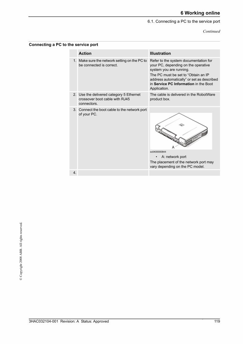
6 Working online6.1. Connecting a PC to the service port
1193HAC032104-001 Revision: A Status: Approved
© C
opyr
ight
200
8 A
BB
. All
right
s res
erve
d.
Connecting a PC to the service port
Action Illustration
1. Make sure the network setting on the PC to be connected is correct.
Refer to the system documentation for your PC, depending on the operative system you are running.The PC must be set to “Obtain an IP address automatically” or set as described in Service PC Information in the Boot Application.
2. Use the delivered category 5 Ethernet crossover boot cable with RJ45 connectors.
The cable is delivered in the RobotWare product box.
3. Connect the boot cable to the network port of your PC.
xx0400000844
• A: network portThe placement of the network port may vary depending on the PC model.
4.
Continued
6 Working online6.2. Network settings
3HAC032104-001 Revision: A Status: Approved120
© C
opyr
ight
200
8 A
BB
. All
right
s res
erve
d.
6.2. Network settings
Overview This topic describes the network settings for a PC connected to a controller, which is a prerequisite for working online.
You can connect the PC to the controller through an Ethernet network in the following ways:
• Local network connection
• Service port connection
• Remote network connection
Local network connection You can connect your PC to the same Ethernet network that the controller is connected to. When the PC and the controller are connected correctly and to the same subnet, the controller will be automatically detected by RobotStudio.
The network settings for the PC depend on the network configuration. For setting up the PC, contact the network administrator.
Service port connectionWhen connecting to the controller's service port, you can either obtain an IP address for the PC automatically, or you can specify a fixed IP address.
If you are not sure how to set up the service port connection, contact the network administrator.
Automatic IP addressThe controller's service port has a DHCP server that will automatically give your PC an IP address if it is configured for this. For detailed information see Windows help on configuring TCP/IP.
Fixed IP addressInstead of obtaining an IP address automatically, you can also specify a fixed IP address on the PC you connect to the controller.
Use the following settings for a fixed IP address:
For detailed information about how to set up the PC network connection, see Windows help on configuring TCP/IP.
Property Value
IP address 192.168.125.2
Subnet mask 255.255.255.0
Continues on next page

6 Working online6.2. Network settings
1213HAC032104-001 Revision: A Status: Approved
© C
opyr
ight
200
8 A
BB
. All
right
s res
erve
d.
NOTE!Obtaining an IP address automatically might fail if the PC already has an IP address from another controller or Ethernet device.
To ensure that you get a correct IP address if the PC was previously connected to an Ethernet device, do one of the following:
• Restart the PC before connecting to the controller.
• Run the command ipconfig /renew from the command prompt after connecting the PC to the controller.
Connecting to the controller 1. Make sure the PC is connected to the controller's service port and that the controller is
running.
2. On the Application menu, point to Online and then click One Click Connect.
3. Select the controller in the Online tab
4. Click Request Write access.
If the controller is in mode Then
Auto You will now get Write Access if it is available.
Manual A message box on the FlexPendant will allow you to grant remote Write Access to RobotStudio Online.
Continued
6 Working online6.3. User Authorization
3HAC032104-001 Revision: A Status: Approved122
© C
opyr
ight
200
8 A
BB
. All
right
s res
erve
d.
6.3. User Authorization
OverviewThis section describes the controller's User Authorization System (UAS), which restricts what different users are allowed to do with the robot. This is for protecting data and functionality from unauthorized use.
The user authorization is managed by the controller, which means that the UAS settings remain for the controller regardless of which system it is running. It also means that the UAS settings apply to all tools for communicating with the controller, like RobotStudio Online or the FlexPendant. The UAS settings defines the users and groups that can access the controller, and what actions they are granted access to.
For procedures, see User Accounts on page 282.
UsersIn UAS users are accounts with which persons log on to the controller. Furthermore, the users are added to groups to which access grants are given.
The users are defined in the controller by a user name and a password. For logging on to a controller, the user must type in a defined user name with a correct password.
A user can either have the state activated or deactivated in the UAS. When a user is deactivated it is not possible to log on to the controller using that account. It is the UAS administrator that activates and deactivates the users.
The Default userAll controllers have a default user named Default User, which does not have any password and cannot be removed. Other users can be added and removed by the user having the grant Manage UAS settings.
GroupsIn UAS, groups are defined sets of grants for accessing the controller. To the groups you then add the users who shall have the grants defined by the group.
A good practice is to create groups that resembles the professions that work with the robots in your organization. For example, you can create groups for administrators, programmers and operators.
The Default groupAll controllers have a default group named Default Group, to which all grants are given and to which the default user belongs. This group cannot be removed, but it can be changed by the user having the grant Manage UAS settings.
Continues on next page
6 Working online6.3. User Authorization
1233HAC032104-001 Revision: A Status: Approved
© C
opyr
ight
200
8 A
BB
. All
right
s res
erve
d.
NOTE!There is a risk changing the group membership of the default user. If you by mistake clear the Default User check box or any Default Group grant, you will get a warning. Make sure that there is at least one user defined that has the grant Manage UAS settings. If the Default group and no other group have the grant Manage UAS settings, you may lose your ability to manage users and groups.
GrantsGrants are permissions to perform actions or access data on the controller. You use the grants by giving them to groups, to which you then add the users who shall have the grants.
Grants may be either controller grants or application grants. Depending on the actions that you will perform, you may need several grants. For procedures, see UAS Grant Viewer on page 287.
Controller grantsController grants are validated by the robot controller and apply to all tools and devices accessing the controller.
Application grantsApplication grants are used by a specific application, for example the FlexPendant, and will only be valid using that application. Application grants can be added by additional options and used in customer applications.
Continued

6 Working online6.4.1. System Builder Overview
3HAC032104-001 Revision: A Status: Approved124
© C
opyr
ight
200
8 A
BB
. All
right
s res
erve
d.
6.4 The System Builder
6.4.1. System Builder Overview
OverviewThis section describes how you create, build, modify and copy systems to run on virtual and real controllers. These systems may even be converted to boot media and downloaded to a real controlller.
The system points out the robot models and options to use; it also stores configurations and programs for the robots. Therefore, it is good practice to use a unique system for each station even if the stations use the same basic setup. Otherwise, changes in one station may accidently overwrite data used in another station.
About virtual and real systemsThe system you run on virtual controllers can either be a real system built on real RobotWare keys or a virtual system built on virtual keys.
When using real systems, the RobotWare keys define which options and robot models shall be used, thus helping you to configure the system correctly. Real systems can be run both on virtual controllers and real IRC5 controllers.
When using virtual keys, all options and robot models are available, which is useful for evaluation purposes, but requires more configuration when creating the system. Systems built on virtual keys can only be run on virtual controllers.
PrerequisitesCreating a system entails applying a predefined template to a station, reusing an existing system or letting RobotStudio propose a system based on a layout.
To create a system, the following conditions must be met:
• The RobotWare media pool must be installed on your PC.
• You must have a RobotWare key for the system, if creating a system to run on a real controller. The RobotWare key is a license key that determines which robot models to use and which RobotWare options to run on the controller. The license key is delivered with the controller.
• If you want to create a system for virtual use only, you can use a virtual key instead. Virtual keys are generated by the wizard. When using virtual keys, you select the robot models and options to use in the Modify Options section of the wizard.
• Downloading to the real controller requires a direct connection from your computer to the service or Ethernet port of the controller.
Continues on next page

6 Working online6.4.1. System Builder Overview
1253HAC032104-001 Revision: A Status: Approved
© C
opyr
ight
200
8 A
BB
. All
right
s res
erve
d.
Administering systemsSystems can be administered from the System Builder dialog box in the following ways:
• View system properties, see Viewing system properties on page 126.
• Build a system, see Building a new system on page 127.
• Modify or delete a system, see Modifying a system on page 130.
• Copy a system, see Copying a system on page 134.
• Create a system from backup, see Creating a system from backup on page 135.
• Download a system to a controller, see Downloading a system to a controller on page 136.
• Create boot media, see Creating boot media on page 137.
Continued

6 Working online6.4.2. Viewing system properties
3HAC032104-001 Revision: A Status: Approved126
© C
opyr
ight
200
8 A
BB
. All
right
s res
erve
d.
6.4.2. Viewing system properties
OverviewAll systems you create with the System Builder are stored locally on your computer. It is recommended that you store them in one or more dedicated system directories.
Viewing system propertiesTo view system properties and add comments, follow these steps:
1. In the System Builder dialog box, select a system from the Systems box.
If necessary, in the System directory list, you can navigate to the folder in which your systems are stored
2. The system properties are then displayed in the System Properties box. Optionally, type a comment in the Comments box, and click Save.

6 Working online6.4.3. Building a new system
1273HAC032104-001 Revision: A Status: Approved
© C
opyr
ight
200
8 A
BB
. All
right
s res
erve
d.
6.4.3. Building a new system
Overview The New Controller System Wizard, used for building a new system, is launched from the System Builder.
Starting the wizard To start the wizard, follow these steps:
1. Click System Builder to bring up a dialog box.
2. In the Actions group, click Create New. This starts the wizard.
3. Read the information on the welcome page and click Next.
Specifying the name and locationTo determine where on your computer to store the system you are creating, follow these steps:
1. In the Name box, enter a name for the system you are creating.
2. In the Path box, enter the path to the system directory in which you will store the system.
You can also click the Browse button and browse to the system directory.
3. Click Next.
Entering the RobotWare keysThe RobotWare keys determine which RobotWare versions and parts to use in the system.
Creating a system to run on either IRC5 controllers or virtual controllers requires at least two keys: one for the controller module and one for each drive module in the cabinet. The keys are delivered together with the controller.
For creating a system to run on virtual controller only (for example, in Virtual IRC5), you can use virtual keys. Virtual keys give access to all options and robot models, but limits the use of the system to virtual controllers only.
To enter the key for the controller module, follow these steps:
1. In the Controller Key box, enter the controller key. You can also click Browse and browse to the key file. If creating a system for virtual use only, select the Virtual Key check box, and the controller key will be generated by the wizard.
2. In the Media Pool box, enter the path to the media pool. You can also click Browse and browse to the folder.system
3. In the RobotWare Version list, select which version of the RobotWare you want to use. Only RobotWare versions that are valid for the used key are available.
4. Click Next.
Continues on next page

6 Working online6.4.3. Building a new system
3HAC032104-001 Revision: A Status: Approved128
© C
opyr
ight
200
8 A
BB
. All
right
s res
erve
d.
Entering the drive keysTo enter the keys for the drive modules:
1. In the Drive Key box, enter the key for the drive module. You can also click the Browse button and browse to the key file. If you used a virtual controller key, a virtual drive key is already generated by the wizard.
2. Click the right arrow button next to the Drive Key box. The key now appears in the Added drive key list.
For real systems the drive key determines the connected robot model. For virtual systems you select the robot model in the Modify Options page. The default model is IRB140.
3. If you have a MultiMove system, repeat steps 1 and 2 for each drive key to add.
If you have a MultiMove system, make sure that the keys are numbered in the same way as their corresponding drive modules are connected to the controller module. Use the up and down arrows to rearrange the drive keys, if necessary.
4. Choose whether you want to create the system as it is now, or to continue with the wizard.
If you want to create the system as it is now, click Finish.
If you want to modify options, or add options, parameter data or additional files to the home directory, click Next.
Adding additional options Here you can add options, such as external axes and dispense applications, that are not included in the basic system. Options require a license key and must be first imported to the media pool. To add additional options, follow these steps:
1. In the Key box, enter the option key. You can also click the Browse button and browse to the option's key file.
2. Click the Arrow button.
The option that the key unlocks is now displayed in the Added Options list.
3. Repeat steps 1 and 2 for all options you want to include.
4. Choose whether you want to create the system as it is now, or to continue with the wizard.
If you want to create the system as it is now, click Finish.
If you want to modify options, or add parameter data or additional files to the home directory, click Next.
Modifying options Here you can set up and configure the options in your system. For virtual systems, you also select the robot models to use. To modify any options, follow these steps:
1. In the Option tree, expand the option folders to the level where you find the option you want to modify.
Only the options unlocked by the used keys are available.
2. Modify the option.
Continued
Continues on next page

6 Working online6.4.3. Building a new system
1293HAC032104-001 Revision: A Status: Approved
© C
opyr
ight
200
8 A
BB
. All
right
s res
erve
d.
3. Repeat steps 1 and 2 for all options you want to modify.
4. Choose whether you want to create the system as it is now, or to continue with the wizard.
If you want to create the system as it is now, click Finish.
If you want to add parameter data or additional files to the home directory, click Next.
Adding parameter data Parameter data is stored in the parameter data files (.cfg files). Each parameter topic has its own parameter file. You can add only one parameter file for each topic. To add parameter data, follow these steps:
1. In the Parameter data box, enter the path to the folder for the parameter data files. You can also click the Browse button and browse to the folder.
2. In the list of parameter data files, select the file you want to include and press the Arrow button. Repeat for all files you want to include.
The included parameter data files will now appear in the Added parameter data files list.
Repeat steps 1 and 2 for each parameter data file you want to add.
3. Choose whether you want to create the system as it is now, or to continue with the wizard.
If you want to create the system as it is now, click Finish.
If you want to add additional files to the home directory, click Next.
Adding files to the home directoryYou can add any type of file to the system’s home directory. When the system is loaded to a controller, these files will also be loaded. To add files to the system's home directory, follow these steps:
1. In the Files box, enter the path to the folder for the files you want to include. You can also click the Browse button and browse to the folder.
2. In the list of files, select the file to add and click the Arrow button. Repeat for all files you want to add.
The added files will now appear in the Added files list.
3. Choose whether you want to create the system as it is now, or to continue with the wizard.
If you want to create the system as it is now, click Finish.
If you want to read a summary before you create the system, click Next.
Completing the New Controller System Wizard To complete the wizard, follow these steps:
1. Read the system summary.
2. If the system is OK, click Finish.
If the system is not OK, click Back and make modifications or corrections.
Continued
6 Working online6.4.4. Modifying a system
3HAC032104-001 Revision: A Status: Approved130
© C
opyr
ight
200
8 A
BB
. All
right
s res
erve
d.
6.4.4. Modifying a system
Overview The Modify Controller System Wizard, used to modify existing systems, is launched from the System Builder.The wizard helps you with tasks like changing robots, adding and removing external axes and other options. A system that is running must be first shut down before modification.
Starting the wizardTo start the wizard when creating a new station:
1. If the system is currently running, on the Controller menu, point to Shutdown and then click Shutdown.
2. On the Controller menu, click System Builder to bring up a dialog box.
3. In the System directory list, enter or browse to the system directory. Select a system from the list beneath, review the system properties and add and save any comments.
4. In the Actions group, click Modify. This starts the wizard.
5. Read the information on the welcome page and click Next.
Modifying the program revisionThe RobotWare versions that are available for the system are determined by the controller key. The key is essential to the system and cannot be modified.
To use another RobotWare version than the available ones, create a new system with another key.
To optionally modify the program revision, follow the appropriate step or steps:
1. To keep the current RobotWare version, select Yes and then click Next .
2. To replace the current RobotWare version, Select No, replace it..
3. In the Media pool box, enter the path to the media pool. You can also click the Browse button and browse to the folder.
4. In the New program revision box, select which version of RobotWare you want to use. Only RobotWare versions that are valid for the RobotWare key are available.
5. Click Next.
Continues on next page

6 Working online6.4.4. Modifying a system
1313HAC032104-001 Revision: A Status: Approved
© C
opyr
ight
200
8 A
BB
. All
right
s res
erve
d.
Adding or removing drive keysThe drive key corresponds to the drive modules in your controller. For MultiMove systems, you have one drive module (and one key) for each robot. The keys for your system are delivered together with the controller.
the system is created with a vritual controller key, virtual drive keys are generated by the wizard. when you have added one virtual drive key for each robot, you select which robot to use for each key on the Modify Options page.
To optionally add or remove the keys for the drive modules, follow these steps:
1. To add a key for a drive module, enter the key in the Enter Drive Key box. You can also click the Browse button and browse to the key file.
2. Click the right arrow button. The key now appears in the Added drive key list.
If you have a MultiMove system, repeat steps 1 and 2 for each drive key to add.
3. To remove a drive module, select the corresponding key in the Added drive key list and click Remove drive key.
If you have a MultiMove system, repeat step 3 for each drive key to remove.
4. If you have a MultiMove system, make sure that the keys are numbered in the same way as their corresponding drive modules are connected to the controller module. Use the up and down arrows to rearrange the drive keys, if necessary.
5. Choose whether you want to create the system as it is now, or to continue with the wizard.
If you want to create the system as it is now, click Finish.
If you want to modify options, parameter data or add files to or remove files from the home directory, click Next.
Adding or removing additional options To optionally add or remove additional options:
1. To add an addtional option, in the Enter Key box, enter the option key. You can also click the Browse button and browse to the option's key file.
2. Click the Arrow button.
The option that the key unlocks is now displayed in the Added Options list.
3. Repeat steps 1 and 2 for all options you want to include.
4. To remove an additional option, iIn the Added options list, select the option you want to remove.
5. Click Remove.
6. Choose whether you want to create the system as it is now, or to continue with the wizard.
If you want to create the system as it is now, click Finish.
If you want to modify parameter data or add files to or remove files from the home directory, click Next.
Continued
Continues on next page

6 Working online6.4.4. Modifying a system
3HAC032104-001 Revision: A Status: Approved132
© C
opyr
ight
200
8 A
BB
. All
right
s res
erve
d.
Modifying options To optionally modify any options, follow these steps:
1. In the Option tree, expand the option folders to the level where you find the option you want to modify.
Only the options unlocked by the used keys are available.
2. Modify the option.
3. Repeat steps 1 and 2 for all options you want to modify.
4. Choose whether you want to create the system as it is now, or to continue with the wizard.
If you want to create the system as it is now, click Finish.
If you want to modify parameter data or add files to or remove files from the home directory, click Next.
Adding or removing parameter data Parameter data is stored in the parameter data files (.cfg files). each parameter topic has its own parameter file. You can add only one parameter file for each topic. To addor remove parameter data, follow these steps:
1. To add parameter data, in the Parameter data box, enter the path to the folder for the parameter data files. You can also click the Browse button and browse to the folder.
2. In the list of parameter data files, select the file you want to include and press the Arrow button. Repeat for all files you want to include.
The included parameter data files will now appear in the Added parameter data files list.
Repeat steps 1 and 2 for each parameter data file you want to add.
3. To remove parameter data, in the Added parameter data files list, select the parameter data file to remove.
4. Click Remove.
5. Choose whether you want to create the system as it is now, or to continue with the wizard.
If you want to create the system as it is now, click Finish.
If you want to add to or remove files from the home directory, click Next.
Add files to or remove files from the home directoryYou can add any type of file to the system’s home directory, or remove files from it. When the system is loaded to a controller, these files will also be loaded. To optionally add files to or remove files from the system's home directory, follow these steps:
1. To add files, in the Files box, enter the path to the folder for the files you want to include. You can also click the Browse button and browse to the folder.
2. In the list of files, select the file to add and click the Arrow button. Repeat for all files you want to add.
The added files will now appear in the Added files list.
3. To remove files, in the Added files list, select the file to remove.
Continued
Continues on next page

6 Working online6.4.4. Modifying a system
1333HAC032104-001 Revision: A Status: Approved
© C
opyr
ight
200
8 A
BB
. All
right
s res
erve
d.
4. Click Remove.
5. Choose whether you want to create the system as it is now, or to continue with the wizard.
If you want to create the system as it is now, click Finish.
If you want to read a summary before you create the system, click Next.
Complete the Modify Controller System wizard To complete the wizard, follow these steps:
1. Read the system summary.
2. If the system is OK, click Finish.
If the system is not OK, click Back and make modifications or corrections.
Result Modifications will take effect when the wizard is completed.
If the system has been downloaded to a controller, it must be downloaded again before the modifications will take effect on the controller.
Deleting a systemTo delete a system, follow this steps:
1. From the System Builder dialog box, select the system and then click Delete.
Continued

6 Working online6.4.5. Copying a system
3HAC032104-001 Revision: A Status: Approved134
© C
opyr
ight
200
8 A
BB
. All
right
s res
erve
d.
6.4.5. Copying a system
Copy a systemTo copy a system, follow these steps:
1. From the System Builder dialog box, select the system and then click Copy to bring up a dialog box.
2. Enter a name for the new system and a path, and then click OK.

6 Working online6.4.6. Creating a system from backup
1353HAC032104-001 Revision: A Status: Approved
© C
opyr
ight
200
8 A
BB
. All
right
s res
erve
d.
6.4.6. Creating a system from backup
OverviewThe Create System from Backup Wizard, which creates a new system from a controller system backup, is launched form the System Builder. In addition, you can change the program revision and options.
Starting the wizardTo start the wizard, follow these steps:
1. From the System Builder dialog box, click Create from Backup. This starts the wizard.
2. Read the information on the welcome page and click Next.
Specifying the name and locationTo specify the destination folder, follow these steps:
1. In the Name box, enter a name for the system you are creating.
2. In the Path box, enter the path to the system directory in which you will store the system.
You can also click the Browse button and browse to the system directory.
3. Click Next.
Locating the backupTo locate a system from backup, follow these steps:
1. In the Backup folder box, enter the path to the backup folder. Alternatively, click the Browse button to browse to it. Click Next.
2. In the Media Pool box, enter the path to the media pool containing the appropriate RobotWare program. Confirm the backup information that now appears in the wizard. Click Next.

6 Working online6.4.7. Downloading a system to a controller
3HAC032104-001 Revision: A Status: Approved136
© C
opyr
ight
200
8 A
BB
. All
right
s res
erve
d.
6.4.7. Downloading a system to a controller
OverviewAll systems you access from the System Builder are stored on your computer. If you wish to run a system on a robot controller, you must first load it to the controller, which then requires a restart.
Load a system To load a system to a controller, follow these steps:
1. From the System Builder dialog box, select a system and then click Download to Controller to bring up a dialog box.
2. Specify the Destination Controller for the system.
3. Optionally, click Test Connection to confirm that the connection between the computer and the Controller is OK.
4. Click Load.
5. Answer Yes to the question Do you want to load the system.
You can select by using the... if... Select controller from list option the controller has been detected automati-
cally.
Specify IP address or controller name option
your PC and the robot is connected to the same network. You can only use the controller name in DHCP networks.
Use service port option your PC is directly connected to the control-ler's service port.
Yes There will be a restart and the system is downloaded to controller.
No There will be no restart. With the next restart the system will be downloaded to controller.
Cancel The downloading is canceled.

6 Working online6.4.8. Creating boot media
1373HAC032104-001 Revision: A Status: Approved
© C
opyr
ight
200
8 A
BB
. All
right
s res
erve
d.
6.4.8. Creating boot media
OverviewBoot media is an entire system which the System Builder packs to a single file and commonly stores on a hard disk or USB memory. The controller then accesses the file through its Ethernet port or USB port, respectively.
Creating boot mediaTo create boot media, follow these steps:
1. From the System Builder dialog box, select a system and then click Boot Media.
2. In the Path box, enter the path to the folder where you want to store the boot media file. Alternatively, browse to the location.
3. Click OK.
ResultTo load the boot media system to a controller, first connect it and then restart the controller with the advanced restart method X-start.

6 Working online6.4.9.1. A MultiMove system with two coordinated robots
3HAC032104-001 Revision: A Status: Approved138
© C
opyr
ight
200
8 A
BB
. All
right
s res
erve
d.
6.4.9. Examples using the System Builder Offline
6.4.9.1. A MultiMove system with two coordinated robots
OverviewIn this example we will use the System Builder to create a coordinated offline system with one IRB2400 and one IRB1600 robot to use in a new RobotStudio station.
Starting the New Controller System WizardTo create a system like the one described above, follow these steps:
1. Click System Builder to bring up the dialog box.
2. In the dialog box, click Create New to bring up the New Controller System Wizard.
3. Read the welcome text, and click Next to continue to the next page.
Entering the name and path1. In the Name box, enter the name of the system. The name must not contain blank spaces
or non-ASCII characters.
In this example, name the system MyMultiMove.
2. In the Path box, enter the path for the folder to save the system in, or click the Browse button to browse to the folder or create a new one.
In this example, save the system in C:\Program Files\ABB Industrial IT\Robotics IT\RobotStudio\ABB Library\Training Systems.
3. Click Next to continue to the next page.
Entering the controller key1. Select the Virtual key check box. A virtual controller key now appears in the Controller
Key box. In this example we will use the default media pool and RobotWare version.
2. Click Next to continue to the next page.
Entering drive keys1. Click the Right Arrow button next to the Enter Drive key box twice to create one drive
key for each robot.
2. Click Next to continue to the next page.
Continues on next page

6 Working online6.4.9.1. A MultiMove system with two coordinated robots
1393HAC032104-001 Revision: A Status: Approved
© C
opyr
ight
200
8 A
BB
. All
right
s res
erve
d.
Adding optionsThis system does not require any additional option keys. Click Next and continue to the next page of the wizard.
Modifying optionsWhen creating robot systems from real robot keys, the key sets the options. But since we are using a virtual key, we have to set the options manually.
To set the options necessary for a MultiMove, follow these steps:
1. Scroll down to the RobotWare / Motion Coordination 1 group and select the MultiMove Coordinated check box.
2. Scroll down to the RobotWare / I/O control group and select the Multitasking and the Advanced RAPID check boxes.
3. Scroll down to the DriveModule1 / Drive module application group and expand the ABB Standard manipulator option. Select the IRB 2400 Type A option, manipulator variant IRB 2400L Type A.
4. Scroll down to the DriveModule2 / Drive module application group and expand the ABB Standard manipulator option. Select the IRB 1600 option, manipulator variant IRB 1600-5/1.2.
5. Click Finish and the system will be created.
Continued

6 Working online6.4.9.2. A system with support for one robot and one positioner external axis
3HAC032104-001 Revision: A Status: Approved140
© C
opyr
ight
200
8 A
BB
. All
right
s res
erve
d.
6.4.9.2. A system with support for one robot and one positioner external axis
OverviewIn this example we will use the System Builder to create an offline system to use in a new RobotStudio station with one IRB1600 robot and one IRBP 250D positioner external axis.
PrerequisitesWhen creating systems for positioner external axes, you need the media pool and the license key file for that specific positioner. In this example we will use a media pool and license key file for a demo positioner.
Paths to files and folders assume that RobotStudio and the RobotWare media pool have been installed at their default locations on Windows XP. If not, adjust the paths accordingly.
Starting the New Controller System WizardTo create a system like the one described above, follow these steps:
1. Click System Builder to bring up a dialog box.
2. In the dialog box, click Create New to bring up the New Controller System Wizard.
3. Read the welcome text, and click Next to continue to the next page.
Entering the controller key1. Select the Virtual key check box. A virtual controller key now appears in the Controller
Key box. In this example we will use the default media pool and RobotWare version.
2. Click Next to continue to the next page.
Entering drive keys1. Click the Right Arrow button next to the Enter Drive key box to create one drive key
for the robot.
2. Click Next to continue to the next page.
Adding optionsThis is where we point out the key file for the positioner.
1. Next to the Enter key box, click the browse button and select the key file.
In this example, browse to and select the file extkey.kxt in the folder C:\Program Files\ABB Industrial IT\Robotics IT\MediaPool\3HEA-000-00022.01.
TIP!In the MediaPool folder media pools for several standard positioners are installed. They are named by the positioner’s article number, with a suffix that indicates if it is configured for single-robot or MultiMove systems.
2. Click the Right Arrow button next to the Enter key box to add the key for the positioner.
3. Click Next and continue to the next page of the wizard.
Continues on next page

6 Working online6.4.9.2. A system with support for one robot and one positioner external axis
1413HAC032104-001 Revision: A Status: Approved
© C
opyr
ight
200
8 A
BB
. All
right
s res
erve
d.
Modifying optionsWhen creating robot systems from real robot keys, the key sets the options. But since we are using a virtual key, we have to set the options manually. To set the options necessary for a positioner, follow these steps:
1. Scroll down to the RobotWare / Hardware group and select the 709-x DeviceNet check box.
This option is for the communication between the controller and the track external axis.
2. Scroll down to the RobotWare / Motion coordination part 2 group and select the Multiple Axis Positioner check box.
This option applies since the positioner has multiple axes.
3. Scroll down to the RobotWare / I/O control group and select the Logical Cross Connection check box.
This option is for the communication between the virtual controller and the track external axis.
4. Scroll down to the DriveModule1 / Drive module application group and expand the ABB Standard manipulator option. Select the IRB 1600 option.
This option sets the robot to an IRB 1600-5/1.2.
5. Scroll down to the DriveModule1 / Additional axes configuration group and expand the Add axes IRB/drive module 1600/2400/260 option and select the R2C2 Add drive option.
Expand the Drive type in position Z4 and select the753-1 drive C in pos Z4 option.
Expand the Drive type in position Y4 and select the754-1 drive C in pos Y4 option.
Expand the Drive type in position X4 and select the755-1 drive C in pos X4 option.
This option adds drive modules for the positioner axes.
6. Click Finish and the system will be created. When starting the system in a RobotStudio station, you have to set up the system to load a model for the positioner and to get the motions to work properly. See Placing external axes on page 64 for more information.
Continued

6 Working online6.4.9.3. Options settings for systems with positioners
3HAC032104-001 Revision: A Status: Approved142
© C
opyr
ight
200
8 A
BB
. All
right
s res
erve
d.
6.4.9.3. Options settings for systems with positioners
OverviewThis is an overview of the RobotWare options to set when creating a system for positioner external axes. Note that besides setting the RobotWare options, you must add an additonal option key for the positioner.
Media pools and option keys for the positionersIf you have the media pool and option key for your positioner, you can use these files.
If not, media pools for standard positioners are installed with RobotStudio. The path to these media pools in a default installation is: C.\program files\ABB Industrial IT\Robotics IT\MediaPool. In this folder a media pool for each positioner is located. These are named by the article number of the positioner, with a suffix that indicates if it is configured for a single-robot or a MultiMove system.
In the Add additional options page of the System Builder, you should add the option for the positioner by opening the mediapool folder for the positioner to add and selecting the extkey.kxt file.
Options for positioners in singe-robot systemsWhen adding a positioner to a single-robot system, the positioner will be added to the same task as the robot. Below, the options to set on the Modify Options page of the System Builder for such a system are listed:
• RobotWare > Hardware > 709-x DeviceNet > 709-1 Master/Slave Single
• RobotWare > Motion coordination part 2 > Multiple Axis Positioner
• RobotWare > I/O control > Logical Cross Connections
• Optionally, for using the system with ArcWare also add RobotWare > Application Arc > 633-1 Arc
• DriveModule 1 > Additional axes configuration > Add axes IRB/Drive module for your robot model > RC2C Add drive > 753-1 Drive C in pos Z4 > 754-2 Drive T in pos Y4 > 755-3 Drive U in pos X4
Continues on next page

6 Working online6.4.9.3. Options settings for systems with positioners
1433HAC032104-001 Revision: A Status: Approved
© C
opyr
ight
200
8 A
BB
. All
right
s res
erve
d.
Options for positioners in MultiMove robot systemsWhen adding a positioner to a MultiMove robot system, the positioner shall be added to a task of its own (thus you also have to add a drive key for the positioner). Below, the options to set on the Modify Options page of the System Builder for such a system are listed:
• RobotWare > Hardware > 709-x DeviceNet > 709-1 Master/Slave Single
• RobotWare > Motion coordinated part 1 > 604-1 MultiMove Coordinated Optionally, expand the MultiMove Coordinated option and select process options for the robots.
• RobotWare > Motion coordination part 2 > Multiple Axis Positioner
• RobotWare > I/O control > Logical Cross Connections
• Optionally, for using the system with ArcWare, add RobotWare > Application Arc > 633-1 Arc
• DriveModule 1 > Additional axes configuration > Add axes IRB/Drive module for your robot model > RC2C Add drive > 753-1 Drive C in pos Z4 > 754-2 Drive T in pos Y4 > 755-3 Drive U in pos X4. For the other drive modules, no additional axes should be configured.
Continued

6 Working online6.5. Handle I/O
3HAC032104-001 Revision: A Status: Approved144
© C
opyr
ight
200
8 A
BB
. All
right
s res
erve
d.
6.5. Handle I/O
OverviewThe I/O system handles input and output signals to and from the controller. Below are the parts of the system described, as well as common types of signals.
The I/O system window is used to view and set previously configured signals, and to activate and deactivate I/O units.
The I/O systemThe I/O system of a controller consists of I/O buses, I/O units and I/O signals. The I/O buses are the controller's connections for I/O units (for instance I/O boards) and the I/O units contain channels for the actual signals.
The I/O buses and units are displayed in the robot view, as child nodes under each controller and the I/O signals are displayed in the I/O window.
I/O signalsI/O signals are used to communicate between the controller and external equipment, or to change variables within a robot program.
Input signalsInput signals notify something for the controller, for instance a feeder belt can set an input signal when it has positioned a work piece. The input signal can then be programmed to start a specific part of the robot program.
Output signalsThe controller uses output signals to notify that a specified condition has been fulfilled. For instance, after the robot has finished its sequence, an output signal can be set. This signal can then be programmed to start a feeder belt, update a counter or trigger any other action.
Simulated signalsA simulated signal is a signal that is manually given a specific value that overrides the actual signal. Thus simulated signals might be useful for testing robot programs without activating or running equipment.
Virtual signalsVirtual signals are signals that are not configured to belong to a physical I/O unit. Instead, they reside inside the controller's memory. A common use for virtual signals is to set variables and store changes in a robot program.
ProceduresFor using the I/O system window, see Inputs / Outputs on page 258.
For adding a signal, see Add signals on page 268.
6 Working online6.6. Configure systems
1453HAC032104-001 Revision: A Status: Approved
© C
opyr
ight
200
8 A
BB
. All
right
s res
erve
d.
6.6. Configure systems
Configuring system parametersSystem parameters may be configured as follows:
• To view topics, types, instances and parameters
• To edit the parameters of an instance
• To copy and paste instances
• To add and delete instances
• To load and save complete configuration files to and from controllers
When working with configurations, the following tools, see Configuration editor on page 272, are useful:
NOTE!To edit system parameters, you must have write access to the controller.
Terms
Viewing configurations 1. To view the topics of a controller, from the Offline/Online tab, expand the Configuration
node for the controller.
All topics in are now displayed as child nodes to the Configuration node.
2. To view the types and instances of a topic, double-click the topic node for the topic to view.
Tool Use
The Configuration Editor
With the Configuration Editor you work with the types and instances of a specific topic.
The Instance Editor With the Instance Editor, you specify the values of the parameters in the instances of system parameter types.
System parameters The sum of all parameters that configure the system, these are divided into topics and types.
Topic A collection of parameters relating to a specific area, and the highest level in the system parameter structure. Examples are Controller, Communication and Motion.
Type A set of parameters for a specific configuration task. A type can be seen as a pattern describing the construction and properties for the parameters included in the task. For instance, the type Motion System defines which parameters shall be used for configuring a motion system.
Instance An actualization of a type, an instance is a specific set of parameters with unique values created from a type pattern. In the Configuration Editor, each row in the Instance list is an instance of the type selected in the Type list.
Parameter A property to set when configuring the robot system.
Configuration file Contains all public parameters of a specific topic.
Continues on next page

6 Working online6.6. Configure systems
3HAC032104-001 Revision: A Status: Approved146
© C
opyr
ight
200
8 A
BB
. All
right
s res
erve
d.
The Configuration Editor is now opened, listing all types of the topic in the Type name list. In the Instance list, each instance of the type selected in the Type name list is displayed as row. The parameter values of the instances are displayed in the columns of the instance list.
3. To view detailed parameter information for an instance, double-click the instance.
The instance editor now displays the current value, restrictions and limits of each parameter in the instance.
Editing parametersYou can either edit the parameters of one single instance, or you can edit several instances at one time. Editing several instances at one time is useful when you want to change the same parameter in several instances, like when moving signals from one I/O unit to another.
1. In the Offline/Online tab, expand the Controller and the Configuration node and double-click the topic that contains the parameters to edit.
This opens the Configuration Editor.
2. In the Type name list of the Configuration Editor, select the type that the parameter to edit belongs to.
The instances of the type is now displayed in the Instance list of the Configuration Editor.
3. In the Instance list, select the instances to edit and press the Enter Key. To select several instances at once, hold down the SHIFT or CTRL key while selecting.
The Instance Editor is now displayed.
4. In the Parameter list of the Instance Editor, select the parameter to edit and change the value of the parameter in the Value box.
When editing several instances at one time, the parameter values you specify will be applied to all instances. For parameters that you do not specify any new value, each instance will keep its existing value for that parameter.
5. Click OK to apply the changes to the configuration database of the controller.
For many parameters, the changes will not take affect until the controller is restarted. If your changes require a restart, you will be notified of this.
You have now updated the controller's system parameters. If the changes require a restart of the controller, the changes will not take affect until you do this. If you are going to make several changes, you can wait with the restart until all changes are done.
Adding instancesWith the Configuration Editor, you can select a type and create a new instance of it. For example, adding a new instance of the type Signal creates a new signal in the system.
1. In the Offline/Online tab, expand the Controller and the Configuration node and double-click the topic that contains the type of which you want to add an instance.
This opens the Configuration Editor.
2. In the Type name list of the Configuration Editor, select the type of which you want to add an instance.
Continued
Continues on next page

6 Working online6.6. Configure systems
1473HAC032104-001 Revision: A Status: Approved
© C
opyr
ight
200
8 A
BB
. All
right
s res
erve
d.
3. On the Controller menu, point to Configuration and click Add type (the word type is replaced by the type you selected previously).
You can also right-click anywhere in the configuration editor and then select Add type from the shortcut menu.
A new instance with default values is added and displayed in the Instance Editor window.
4. If required, edit the values.
5. Click OK to save the new instance.
The values in the new instance are now validated. If the values are valid, the instance is saved. Otherwise, you will be notified of which parameter values to correct.
For many instances, the changes will not take affect until the controller is restarted. If your changes require a restart you will be notified of this.
You have now updated the controller's system parameters. If the changes require a restart of the controller, the changes will not take affect until you do this. If you are going to make several changes, you can wait with the restart until all changes are done.
Copying an instance1. In the Offline/Online tab, expand the Controller and the Configuration node and
double-click the topic that contains the instance to copy.
This opens the Configuration Editor.
2. In the Type name list of the Configuration Editor, select the type of which you want to copy an instance.
3. In the Instance list, select one or several instances to copy.
If you select several instances and they don't have the same value for all parameters, these parameters will have no default values in the new instances.
4. On the Controller menu, point to Configuration and click Copy Type (the word type is replaced by the type you selected previously).
You can also right-click the instance to copy and then select Copy Type from the shortcut menu.
A new instance with the same values as the one you copied is added and displayed in the Instance Editor window.
5. Change the name of the instance. If required, also edit the other values.
6. Click OK to save the new instance.
The values in the new instance are now validated. If the values are valid, the instance is saved. Otherwise, you will be notified of which parameter values to correct.
For many instances, the changes will not take affect until the controller is restarted. If your changes require a restart you will be notified of this.
You have now updated the controller's system parameters. If the changes require a restart of the controller, the changes will not take affect until you do this. If you are going to make several changes, you can wait with the restart until all changes are done.
Continued
Continues on next page
6 Working online6.6. Configure systems
3HAC032104-001 Revision: A Status: Approved148
© C
opyr
ight
200
8 A
BB
. All
right
s res
erve
d.
Deleting an instance 1. In the Offline/Online tab, expand the Controller and the Configuration node and
double-click the topic that contains the type of which you want to delete an instance.
This opens the Configuration Editor.
2. In the Type name list of the Configuration Editor, select the type of which you want to delete an instance.
3. In the Instance list, select the instance to delete.
4. On the Controller menu, point to Configuration and then click Delete type (the word type is replaced by the type you selected previously).
You can also right-click the instance to delete and then select Delete type from the shortcut menu.
5. A message box is displayed, asking if you want to delete or keep the instance. Click Yes to confirm that you want to delete it.
For many instances, the changes will not take affect until the controller is restarted. If your changes require a restart you will be notified of this.
You have now updated the controller's system parameters. If the changes require a restart of the controller, the changes will not take affect until you do this. If you are going to make several changes, you can wait with the restart until all changes are done.
Save one configuration fileThe system parameters of a configuration topic can be saved to a configuration file, stored on the PC or any of its network drives.
The configuration files can then be loaded into a controller. They are thereby useful as backups, or for transferring configurations from one controller to another.
1. In the Offline/Online tab, expand the Configuration node and select the topic to save to a file.
2. On the Controller menu, point to Configuration and select Save System Parameters.
You can also right-click the topic and then select Save System Parameters from the shortcut menu.
3. In the Save As dialog box, browse for the folder to save the file in.
4. Click Save.
Saving several configuration files1. In the Offline/Online tab, select the Configuration node.
2. On the Controller menu, point to Configuration and click Save System Parameters.
You can also right-click the configuration node and then click Save System Parameters.
3. In the Save System Parameters dialog box, select the topics to save to files. Then click Save.
4. In the Browse for Folder dialog box, browse for the folder to save the files in, and then click OK.
The selected topics will now be saved as configuration files with default names in the specified folder.
Continued
Continues on next page
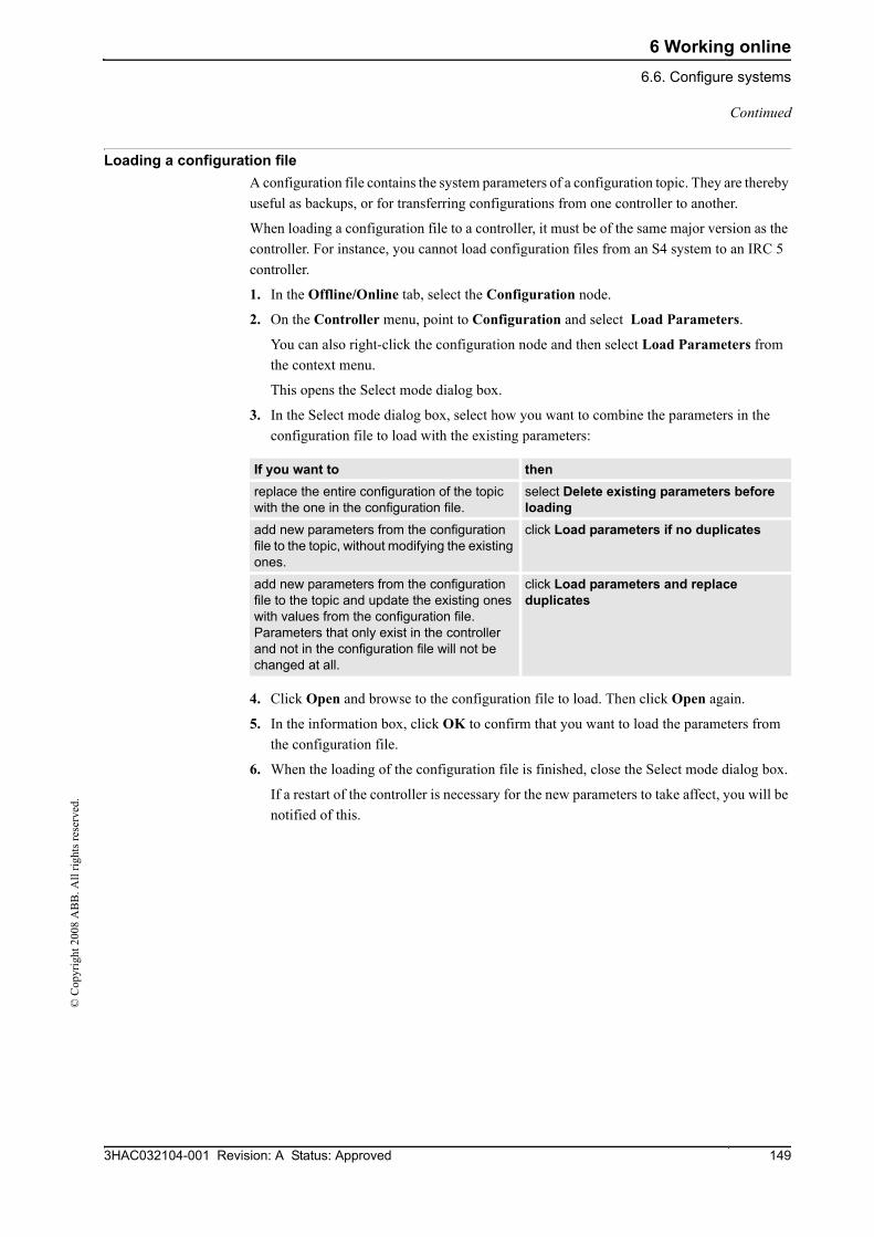
6 Working online6.6. Configure systems
1493HAC032104-001 Revision: A Status: Approved
© C
opyr
ight
200
8 A
BB
. All
right
s res
erve
d.
Loading a configuration file A configuration file contains the system parameters of a configuration topic. They are thereby useful as backups, or for transferring configurations from one controller to another.
When loading a configuration file to a controller, it must be of the same major version as the controller. For instance, you cannot load configuration files from an S4 system to an IRC 5 controller.
1. In the Offline/Online tab, select the Configuration node.
2. On the Controller menu, point to Configuration and select Load Parameters.
You can also right-click the configuration node and then select Load Parameters from the context menu.
This opens the Select mode dialog box.
3. In the Select mode dialog box, select how you want to combine the parameters in the configuration file to load with the existing parameters:
4. Click Open and browse to the configuration file to load. Then click Open again.
5. In the information box, click OK to confirm that you want to load the parameters from the configuration file.
6. When the loading of the configuration file is finished, close the Select mode dialog box.
If a restart of the controller is necessary for the new parameters to take affect, you will be notified of this.
If you want to then replace the entire configuration of the topic with the one in the configuration file.
select Delete existing parameters before loading
add new parameters from the configuration file to the topic, without modifying the existing ones.
click Load parameters if no duplicates
add new parameters from the configuration file to the topic and update the existing ones with values from the configuration file. Parameters that only exist in the controller and not in the configuration file will not be changed at all.
click Load parameters and replace duplicates
Continued
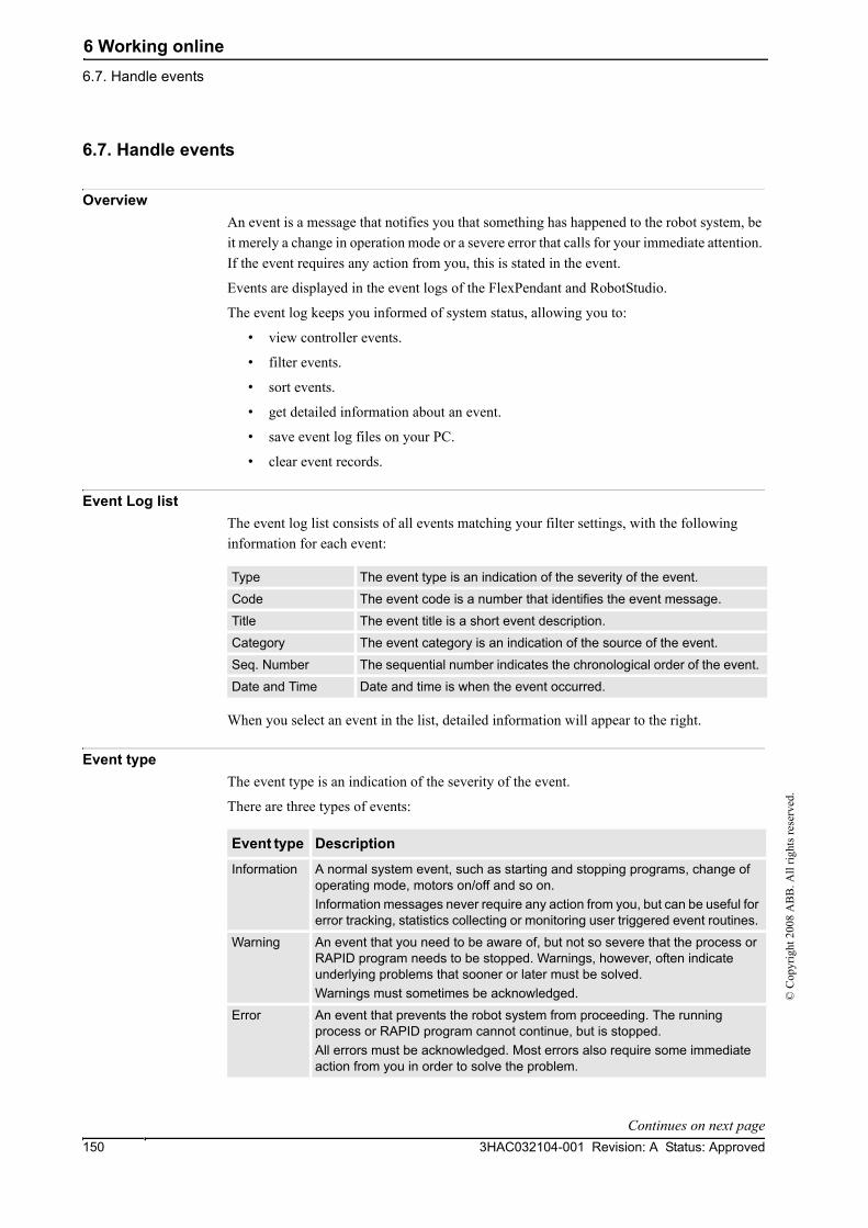
6 Working online6.7. Handle events
3HAC032104-001 Revision: A Status: Approved150
© C
opyr
ight
200
8 A
BB
. All
right
s res
erve
d.
6.7. Handle events
Overview An event is a message that notifies you that something has happened to the robot system, be it merely a change in operation mode or a severe error that calls for your immediate attention. If the event requires any action from you, this is stated in the event.
Events are displayed in the event logs of the FlexPendant and RobotStudio.
The event log keeps you informed of system status, allowing you to:
• view controller events.
• filter events.
• sort events.
• get detailed information about an event.
• save event log files on your PC.
• clear event records.
Event Log listThe event log list consists of all events matching your filter settings, with the following information for each event:
When you select an event in the list, detailed information will appear to the right.
Event typeThe event type is an indication of the severity of the event.
There are three types of events:
Type The event type is an indication of the severity of the event.
Code The event code is a number that identifies the event message.
Title The event title is a short event description.
Category The event category is an indication of the source of the event.
Seq. Number The sequential number indicates the chronological order of the event.
Date and Time Date and time is when the event occurred.
Event type Description
Information A normal system event, such as starting and stopping programs, change of operating mode, motors on/off and so on.Information messages never require any action from you, but can be useful for error tracking, statistics collecting or monitoring user triggered event routines.
Warning An event that you need to be aware of, but not so severe that the process or RAPID program needs to be stopped. Warnings, however, often indicate underlying problems that sooner or later must be solved.Warnings must sometimes be acknowledged.
Error An event that prevents the robot system from proceeding. The running process or RAPID program cannot continue, but is stopped. All errors must be acknowledged. Most errors also require some immediate action from you in order to solve the problem.
Continues on next page

6 Working online6.7. Handle events
1513HAC032104-001 Revision: A Status: Approved
© C
opyr
ight
200
8 A
BB
. All
right
s res
erve
d.
NOTE!This information is also indicated by color: blue for information, yellow for warning and red for an error which needs to be corrected in order to proceed
Event code The event code is a number that identifies the event message. Together with the event date and time each event has a unique identity.
Event title The event title is a short description of the event.
Event category The category is an indication of the source of the event.
Depending on how the system is configured, additional categories may exist.
Sequential numberThe sequential number indicates the chronological order of the event; the higher the number the more recently the event occurred.
Date and time Date and time indicate exactly when the event occurred. Along with the event code, this timestamp guarantees that each event has a unique identity.
Event descriptionWhen you select an event in the list, detailed information about it will be displayed to the right. This includes a description, and when appropritate also consequences, causes and suggested actions to solve the problem.
Category Display
Common All recent events.
Operational Events related to changes in operation or operating mode.
System Events related to the current system.
Hardware Events related to controller hardware.
Program Events related to the running process applications and RAPID programs.
Motion Events related to the movement of robots or other mechanical units .
I/O & Communica-tion
Events related to input and output signals, serial or network communi-cation and process buses.
User Custom messages that have been programed into RAPID programs.
Internal Internal low-level controller errors for ABB service personnel.
Process Events related to Industrial Processes options., such as Spot, Arc and Dispense.
Cfg Errors in a configuration file.
Continued
Continues on next page

6 Working online6.7. Handle events
3HAC032104-001 Revision: A Status: Approved152
© C
opyr
ight
200
8 A
BB
. All
right
s res
erve
d.
Overview The Event Log automatically logs all controller events once it is started. By default, events are displayed in the chronological order specified by Seq Numbers.
NOTE!Any modifications to the list you see will never affect the event log of the controller. What you see is just a copy.
Managing events1. In the Robot View Explorer, select a system.
2. Double-click the Events node.
Retrieving controller eventsTo clear the list and retrieve all existing events from the robot controller:
1. Optionally, save the existing Event Log record.
2. Select whether you want the list to be updated when new events occur , or if you are only interested in viewing events that have already occurred.
3. Click Get to clear the current list, fetch and display all events that are currently stored in the controller log files.
To sort events Click the header for the column you want to sort by. To switch between ascending and descending sorting, click the header once again.
To filter events In the Category list select the event category you want displayed.
To clear the event log Click Clear.This will not affect the event log of the robot controller. It might still be impossible, however, to retrieve all events from a cleared record once again, as the oldest ones may have been erased from the controller hard disk due to lack of space. It is therefore recommended to save the record to a log file before clearing.
To save all events to a single log file on the computer
Check the Log to file check box.If it remains checked, the log file will be updated with new events as they occur.
To save events of one or several categories to files on the computer
Click Save and then make your category choice. Specify the location for the log file(s) in the Browse For Folder dialog and then click OK.If you select All when selecting categories, a log file for each event category will be created.
To ... ...then... get automatic updates when new events occur
check the Auto Update check box. (Checked by default.)
say no to automatic updates when new events occur
clear the Auto Update check box.
Continued

6 Working online6.8. Handle devices
1533HAC032104-001 Revision: A Status: Approved
© C
opyr
ight
200
8 A
BB
. All
right
s res
erve
d.
6.8. Handle devices
OverviewThe Device Browser displays the properties and trends of the various hardware and software devices in a robot controller. It is launched from the Properties command on the Online tab.
For procedures, see Device Browser on page 292.

6 Working online6.8. Handle devices
3HAC032104-001 Revision: A Status: Approved154
© C
opyr
ight
200
8 A
BB
. All
right
s res
erve
d.

7 The Application Menu7.1. Overview
1553HAC032104-001 Revision: A Status: Approved
© C
opyr
ight
200
8 A
BB
. All
right
s res
erve
d.
7 The Application Menu7.1. Overview
OverviewThe Application menu is accessed from the RobotStudio button in the upper left corner of the GUI.

7 The Application Menu7.2. New Station
3HAC032104-001 Revision: A Status: Approved156
© C
opyr
ight
200
8 A
BB
. All
right
s res
erve
d.
7.2. New Station
Creating a station with a template system1. Click New Station to bring up a dialog box.
The Template System icon is already selected by default.
2. In the Select Template System list, either select an appropriate template or click Browse and browse to one.
3. In the System group, enter a name and location, and then click OK.
Creating a station with an existing system1. Click New Station to bring up a dialog box.
2. Click the Existing system icon to bring up the Existing System dialog box.
3. In the Select System Pool list, select a folder.
4. In the Systems Found list, select a system.
5. Click OK.
Creating an empty station1. Click New Station to bring up a dialog box.
2. Click the Empty Station icon. The station will be created and visible in the graphics window.

7 The Application Menu7.3. Screenshot
1573HAC032104-001 Revision: A Status: Approved
© C
opyr
ight
200
8 A
BB
. All
right
s res
erve
d.
7.3. Screenshot
PrerequisitesFor optimal results, first configure the options, see Options:General:Screenshot on page 161.
Capturing the screen1. Click Screenshot.
If the image is saved to file, this is reported in the output window.

7 The Application Menu7.4. Pack & Go
3HAC032104-001 Revision: A Status: Approved158
© C
opyr
ight
200
8 A
BB
. All
right
s res
erve
d.
7.4. Pack & Go
Packing a station1. Click Pack & Go to open the Pack & Go Wizard.
2. On the Welcome to the Pack & Go Wizard page, click Next.
3. On the Destination page, specifiy the destination directory of the package by either entering the path in the box or browsing to it. Click Next.
4. On the Libraries page, select one of the three options. Click Next.
5. On the Systems page, select the check box to include backups of all robot systems. Optionally, select the check box to include a media pool for additional options. Click Next.
6. On the Ready to pack page, review the information and then click Finish.
7. On the Pack & Go succeeded page, review the results and then click Close.

7 The Application Menu7.5. Unpack & Work
1593HAC032104-001 Revision: A Status: Approved
© C
opyr
ight
200
8 A
BB
. All
right
s res
erve
d.
7.5. Unpack & Work
Unpacking a station1. Click Unpack & Work to open the Unpack & Work Wizard.
2. On the Welcome to the Unpack & Work Wizard page, click Next.
3. On the Select package page, specifiy the package to be unpacked by either entering the path in the box or browsing to it. Specify as well the destination directory of the files. Click Next.
4. On the Controller Systems page, specify the path to the media pool and the RobotWare version. Optionally, select the check box to automatically restore backup. Click Next.
5. On the Ready to unpack page, review the information and then click Finish.
6. On the Unpack & Work succeeded page, review the results and then click Close.

7 The Application Menu7.6. RobotStudio Options
3HAC032104-001 Revision: A Status: Approved160
© C
opyr
ight
200
8 A
BB
. All
right
s res
erve
d.
7.6. RobotStudio Options
Common buttons
Options:General:Appearance
Options:General:Licensing
Options:General:Units
Options:General:Advanced
Apply Click this button to save all options in the current page.
Reset Click this button to reset to the settings you had before this session all values that you have changed on the current page.
Default Click this button to reset to their default values all settings on the current page.
Select application language
Select the language to be used.
Select color theme Select the color to be used.
Display Position Edit boxes with Red/Green/Blue background
Select the check box if you want to display the position boxes in the modify dialog boxes with colored background. Default value: selected.
View installed license keys
Click to view the license keys per feature, version, type, expiration date and status.
Request a license Click to request a license.
Install a license Click to install a license.
Set server For managing commuter license keys.
Check out commuter license keys
For managing commuter license keys.
Check in commuter license keys
For managing commuter license keys.
Quantity Select the quantity for which you want to change the units.
Unit Select the unit for the quantity.
Display decimals Enter the number of decimals that you want to be displayed.
Edit decimals Enter the number of decimals that you want when modifying.
Enable Windows Error Reporting
Select this check box to send error data directly to a Microsoft server to be downloaded and analyzed by ABB support. Available only on Windows XP or later.
Number of undo/redo steps
The number of operations that can be undone or redone. Lowering this value can decrease memory usage.
Show acknowledge dialog box when deleting objects
Warns when deleting objects.
Continues on next page
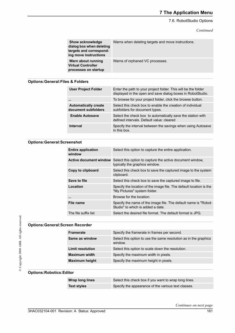
7 The Application Menu7.6. RobotStudio Options
1613HAC032104-001 Revision: A Status: Approved
© C
opyr
ight
200
8 A
BB
. All
right
s res
erve
d.
Options:General:Files & Folders
Options:General:Screenshot
Options:General:Screen Recorder
Options:Robotics:Editor
Show acknowledge dialog box when deleting targets and correspond-ing move instructions
Warns when deleting targets and move instructions.
Warn about running Virtual Controller processes on startup
Warns of orphaned VC processes.
User Project Folder Enter the path to your project folder. This will be the folder displayed in the open and save dialog boxes in RobotStudio.
... To browse for your project folder, click the browse button.
Automatically create document subfolders
Select this check box to enable the creation of individual subfolders for document types.
Enable Autosave Select the check box to automatically save the station with defined intervals. Default value: cleared
Interval Specify the interval between the savings when using Autosave in this box.
Entire application window
Select this option to capture the entire application.
Active document window Select this option to capture the active document window, typically the graphics window.
Copy to clipboard Select this check box to save the captured image to the system clipboard.
Save to file Select this check box to save the captured image to file.
Location Specify the location of the image file. The default location is the "My Pictures" system folder.
... Browse for the location.
File name Specify the name of the image file. The default name is "Robot-Studio" to which is added a date.
The file suffix list Select the desired file format. The default format is JPG.
Framerate Specify the framerate in frames per second.
Same as window Select this option to use the same resolution as in the graphics window.
Limit resolution Select this option to scale down the resolution.
Maximum width Specify the maximum width in pixels.
Maximum height Specify the maximum height in pixels.
Wrap long lines Select this check box if you want to wrap long lines.
Text styles Specify the appearance of the various text classes.
Continued
Continues on next page

7 The Application Menu7.6. RobotStudio Options
3HAC032104-001 Revision: A Status: Approved162
© C
opyr
ight
200
8 A
BB
. All
right
s res
erve
d.
Options:Robotics:Rapid
Options:Robotics:Synchronization
Options:Robotics:Mechanism
Options:Robotics:Virtual FlexPendant
Options:Online:Authentication
Show dialog when warning for globally defined workobjects
Select this check box if you want RobotStudio to display a warning when there are workobjects with the same name that have been declared as in other tasks. Default value: selected.
Show synchronize dialog box after loading program /module
Select this check box if you want the synchronize dialog box to be displayed when you have loaded a program or a module. Default value: selected.
Show notification that default data is used
Select this check box if you want to be notified that wobj0 and/or tool0 is active and will be used in the current action. Default value: selected.
Show synchronization notification
Default value: selected.
Set as active when creating tooldata
Select this check box if you want newly created tooldata to be set as active. Default value: selected.
Set as active when creating workobjects
Select this check box if you want newly created workobjects to be set as active. Default value: selected.
Use default synchroniza-tion locations
Converting data, such as target to Workobject, shall use the default behavior for synchronization locations. Default value: selected.
Show default synchroni-zation locations notifica-tion
Notifies of the behavior above. Default value: selected.
Declaration default locations
Specify the locations for corresponding objects when synchro-nizing to the VC.
Approach Vector Select the approach vector. Default value: Z.
Travel Vector Select the travel vector. Default value: X.
Enable configuration check for jump to target/move instruction
Select this check box if you want to enable the configuration check configurations when jumping to target or move instruc-tions. When selected and a target does not have a validated configuration assigned, you will be asked to set one. When cleared, the configuration closest to the current one is used. Default value: selected.
Always on top Select this check box if you want to have the virtual FlexPendant always on top. Default value: selected.
Enable transparency Select this check box if you want parts of the virtual FlexPendant to be transparent. Default value: selected.
Recent Users Lists the recent users.
Remove/Remove All Click these buttons to remove one or all recent users, respec-tively.
Enable Automatic Logoff Select the check box if you want to log off automatically.
Continued
Continues on next page

7 The Application Menu7.6. RobotStudio Options
1633HAC032104-001 Revision: A Status: Approved
© C
opyr
ight
200
8 A
BB
. All
right
s res
erve
d.
Options:Graphics:Renderer
Options:Graphics:Appearance
Options:Graphics:Performance
The settings you make here are generic for all objects in RobotStudio. With the Graphic Appareance dialog box you can, however, override some of these settings for single objects.
Timeout Determines the length of the session before being automatically logged off.
Select API to use for 3D graphics
Select the low-level API to be used for rendering 3D graphics. The default value is OpenGL, but Direct3D might be faster or stabler.
Background color Click the colored rectangle to change the background color.
Gradient Select the check box if you want to display the background color in gradient style. Default value: cleared.
Show floor Select the check box if you want the floor (at z=0) to be displayed. Change the floor color by clicking the colored rectangle. Default values: selected.
Color Click the colored rectangle to change the color of the floor.
Transparent Select the check box if you want the floor to be transparent. Default values: selected.
Show UCS Grid Select the check box if you want the UCS grid to be displayed. Default value: selected.
Grid Space X Change the UCS grid space in the X coordinate direction by entering the requested value in the box. Default value: 1000 mm (or equivalent in other units).
Grid Space Y Change the UCS grid space in the Y coordinate direction by entering the requested value in the box. Default value: 1000 mm (or equivalent in other units).
Show coordinate system Select the check box if you want the coordinate systems to be displayed. Default value: selected.
Detail level Select if the detail level is to be Auto, Fine, Medium or Coarse. Default value: Auto.
Cull back-facing triangles
Select the check box if you want to ignore the back-facing triangles. Default value: selected.Culling back-facing triangles improves the graphics performance but may give unexpected display if surfaces in models are not faced correctly.
Enable twosided lighting Select the check box if you want to enable two-sided lighting. Default value: cleared.
Cull objects smaller than Select the size in pixels under which objects will be disregarded. Default value: 2 pixels.
Store model data on graphics card (recom-mended)
Select the check box if you want to store the model data on a graphics card. Default value: cleared.Storing model data on a graphics card improves graphics per-formance, but causes stability problems for some hardware combinations.
Continued
Continues on next page

7 The Application Menu7.6. RobotStudio Options
3HAC032104-001 Revision: A Status: Approved164
© C
opyr
ight
200
8 A
BB
. All
right
s res
erve
d.
Options:Graphics:Behavior
Options:Graphics:Geometry
Options:Simulation:Collision
Navigation sensitivity Select the navigation sensitivity when using the mouse movements or navigation buttons by clicking the bar and dragging it into position. Default value: 1.
Selection radius (pixels) Change the selection radius (that is, how close the mouse cursor click must be to an item to be selected) by entering the requested pixel value in the box. Default value: 5.
Selection highlight Set if the selected object shall be distinguished in the Graphics window by a color, by an outline or not at all. Default value: color.
Highlight color Click the colored rectangle to change the highlight color.
Activate selection preview
Select the check box to enable temporarily highlighting of items that may be selected when the mouse cursor passes over them. Default value: selected.
Show local coordinate system for selected objects
Select the check box to show the local coordinate system for the selected objects. Default value: selected.
Normal Tolerance Enter the maximum deviation of surface normals in the Fine, Medium or Coarse boxes. Default values (in deg): Fine: 10, Medium: 22.5, Coarse: 45 (or equivalent in other units).
Surface Tolerance Enter the maximum spatial deviation of surfaces in the Fine, Medium or Coarse boxes. Default values (in deg): Fine: 2, Medium: 10, Coarse: 50 (or equivalent in other units).
Curve Tolerance Enter the maximum spatial deviation of curves in the Fine, Medium or Coarse boxes. Default values (in deg): Fine: 0.2, Medium: 1, Coarse: 5 (or equivalent in other units).
Perform collision detection
Select if collision detection is to be performed during simulation or always. Default value: During simulation.
Stop simulation at collision
Select this check box if you want the simulation to stop at a collision. Default value: cleared.
Log collisions to Output window
Select this check box if you want the collisions to be logged to the output window. Default value: selected.
Log collisions to file: Select this check box if you want to log the collisions to a file. Browse for the file to log in by clicking the browse button. Default value: cleared.
Enable fast collision detection
Select this check box to enhance the performance by detecting collisions between geometrical bounding boxes instead of geometrical triangles. This might result in falsely reported collisions, since the triangles are the true geometry and the bounding boxes always are larger. All true collisions will, however, be reported. The larger the object, the greater the number of false collisions that are likely to be detected.
View Click this button to open the log file specified in the file box in Notepad.
Clear Click this button to delete the log file specified in the file box.
... Click this button to browse for the file in which you want to log the collisions.
Continued
Continues on next page

7 The Application Menu7.6. RobotStudio Options
1653HAC032104-001 Revision: A Status: Approved
© C
opyr
ight
200
8 A
BB
. All
right
s res
erve
d.
Options:Simulation:Virtual Time
Options:Simulation:Accuracy
Virtual Time mode- Free run
This option makes RobotStudio always use the free run mode.
Virtual Time mode - Time Slice
This option makes RobotStudio always use the time slice mode.
Simulation speed Sets the simulation speed relative to real time.
Simulation timestep Specifies the simulation timestep.
Continued

7 The Application Menu7.6. RobotStudio Options
3HAC032104-001 Revision: A Status: Approved166
© C
opyr
ight
200
8 A
BB
. All
right
s res
erve
d.

8 The Home Tab8.1. Overview
1673HAC032104-001 Revision: A Status: Approved
© C
opyr
ight
200
8 A
BB
. All
right
s res
erve
d.
8 The Home Tab8.1. Overview
The Home tabThe Home tab contains the controls required for building stations, creating systems, programing paths and placing items.

8 The Home Tab8.2. ABB Library
3HAC032104-001 Revision: A Status: Approved168
© C
opyr
ight
200
8 A
BB
. All
right
s res
erve
d.
8.2. ABB Library
About this buttonWith this button, you can choose robots, positioners and tracks from their respective galleries.

8 The Home Tab8.3. Import Library
1693HAC032104-001 Revision: A Status: Approved
© C
opyr
ight
200
8 A
BB
. All
right
s res
erve
d.
8.3. Import Library
About this buttonWith this button, you can import equipment, geometries, positioners, robots, tools and training objects to your station libraries.
Click the lower split button to display galleries of tools, conveyors, cabinets and other equipment.

8 The Home Tab8.4. Robot System
3HAC032104-001 Revision: A Status: Approved170
© C
opyr
ight
200
8 A
BB
. All
right
s res
erve
d.
8.4. Robot System
About this buttonWith the Robot System button, you can either create a system from layout or template, choose an existing system, or select a system from a robot gallery.
Creating a system from layout1. Click From Layout to bring up the first page of the wizard.
2. In the Name box, enter the name of the system.
3. In the Location box, enter the path to the folder where the system will be stored. Alternatively, click Browse and browse to the folder.
4. In the Media Pool box, enter the path to the media pool. Alternatively, click Browse and browse to the folder.
5. In the RobotWare Version list, select the version of RobotWare you want to use.
6. Click Next.
7. In the Mechanisms box, select the mechanisms that you want to include in the system.
8. Click Next.
The wizard now proposes a mapping of the mechanisms to a specific motion task, in accordance with the following rules:
• Only one TCP robot is allowed per task.
• Up to six motion tasks may be added, but only four TCP robots can be used, and they must be assigned to the first four tasks.
• The number of tasks may not exceed the number of mechanisms.
• If the system contains one TCP robot and one external axis, they will be assigned to the same task. It is, however, possible to add a new task and assign the external axis to it.
• If the system contains more than one TCP robot, any external axes will be assigned to a separate task. It is, however, possible to move them to other tasks.
• The number of external axes in a task is limited by the number of available drive modules in the cabinet (one for large robots, two for medium, three for small).
Note! If only one mechanism was selected in the previous page, this page will not be shown.
Tasks can be added and removed using the respective buttons; mechanisms can be moved up or down using the respective arrows. To map the mechanisms to tasks, follow this step:
9. Optionally, make any edits in the mapping, and then click Next.
10. Verify the summary and then click Finish.
If the system contains more than one robot, the number of tasks and the baseframe positions of the mechanism should be verified in the System Configuration window.
Continues on next page

8 The Home Tab8.4. Robot System
1713HAC032104-001 Revision: A Status: Approved
© C
opyr
ight
200
8 A
BB
. All
right
s res
erve
d.
Adding a template system1. Click From Template to bring up a dialog box.
2. In the Select Template System list, either select an appropriate template or click Browse and browse to one.
3. In the Libraries group, select whether to import libraries or to use the existing station libraries.
4. In the System group, enter a name and location, and then click OK.
Adding an existing system1. Click Existing to bring up a dialog box.
2. In the Select System Pool list, select a folder.
3. In the Systems Found list, select a system.
4. In the Libraries group, select whether to import libraries or to use the existing station libraries.
5. Click OK.
Selecting a system from a robot gallery1. Click Quick System to bring up a gallery, and then click the appropriate robot.
Continued
8 The Home Tab8.5. Import Geometry
3HAC032104-001 Revision: A Status: Approved172
© C
opyr
ight
200
8 A
BB
. All
right
s res
erve
d.
8.5. Import Geometry
Importing a geometry1. Click Import Geometry.
2. Browse to the library where the geometry is located.
For predefined geometries, click the ABB Library icon to the left in the dialog box.
3. Select the requested geometry and Detail Levels. Click Open.
If you want the geometry to move with another object, attach it to the requested object, see Attach to on page 299.
To modify the detail level for import of geometries, see RobotStudio Options on page 160.

8 The Home Tab8.6.1. Frame
1733HAC032104-001 Revision: A Status: Approved
© C
opyr
ight
200
8 A
BB
. All
right
s res
erve
d.
8.6 Frame
8.6.1. Frame
Creating a frame1. Click Frame.
2. In the dialog box, specify the positions for the frame.
Reference Select the Reference coordinate system to which all positions or points will be related.
Frame Position Click in one of these boxes, and then click the frame position in the graphics window to transfer the values to the Frame Position boxes.
Frame Orientation Specify the coordinates for the frame orientation.
Set as UCS Select this check box to set the created frame as the user coordinate system.

8 The Home Tab8.6.2. Frame from Three Points
3HAC032104-001 Revision: A Status: Approved174
© C
opyr
ight
200
8 A
BB
. All
right
s res
erve
d.
8.6.2. Frame from Three Points
Creating a frame from three points1. Click Frame from Three points to bring up a dialog box.
2. Decide how you want to specify the frame:
3. If you select Position:
• Enter the Position for the object.
• Enter the Point on X axis for the object.
• Enter the Point on X-Y plane for the object.
• Click Create.
4. If you select Three Point:
• Enter the First Point on X axis for the object. This is the point closest to the frame’s origin.
• Enter the Second Point on X axis for the object. This is the point further away in the positive X direction.
• Enter the Point on Y axis for the object.
• Click Create.
The Create Frame From Three Points dialog box
To specify the frame using Select
X, Y and Z coordinates, a point on the X axis and a point in the X-Y plane
Position
two points on the X axis and one point on the Y axis
Three Point
Position Select this option if you want to create the frame by using a position and two points.
Frame Position Click in one of these boxes, and then click the frame position in the graphics window to transfer the values to the Frame Position boxes.
Point on X axis Click in one of these boxes, and then click the point position in the graphics window to transfer the values to the Point on X axis boxes.
Point on X-Y plane Click in one of these boxes, and then click the point position in the graphics window to transfer the values to the Point on X-Y plane boxes.
Three Point Select this option if you want to create the frame by using three points.
First Point on X axis Click in one of these boxes, and then click the point position in the graphics window to transfer the values to the First Point on X axis boxes.
Second Point on X axis Click in one of these boxes, and then click the point position in the graphics window to transfer the values to the Second Point on X axis boxes.
Continues on next page

8 The Home Tab8.6.2. Frame from Three Points
1753HAC032104-001 Revision: A Status: Approved
© C
opyr
ight
200
8 A
BB
. All
right
s res
erve
d.
Point on Y axis Click in one of these boxes, and then click the point position in the graphics window to transfer the values to the Point on Y axis boxes.
Set as UCS Select this check box to set the created frame as the user coordinate system.
Continued

8 The Home Tab8.7. Workobject
3HAC032104-001 Revision: A Status: Approved176
© C
opyr
ight
200
8 A
BB
. All
right
s res
erve
d.
8.7. Workobject
Creating a workobject1. Click Workobject to bring up a dialog box.
2. In the Misc Data group, enter the values for the new workobject.
3. In the User Frame group, do one of the following:
• Set the position of the user frame by entering values for the Position x, y, z and the Rotation rx, ry, rz for the workobject by clicking in the Values box.
• Select the user frame by using the Frame by points dialog box.
4. In the Object Frame group you can reposition the object frame relative to the user frame by doing any of the following:
• Set the position of the object frame by selecting values for Position x, y, z by clicking in the Values box.
• For the Rotation rx, ry, rz, select RPY (Euler XYX) or Quaternion, and enter the rotation values in the Values dialog box.
• Select the object frame by using the Frame by points dialog box.
5. In the Sync Properties group, enter the values for the new workobject.
6. Click Create. The workobject will be created and displayed under the Targets node under the robot node in the Paths&Targets browser.
The Create Workobject dialog box
Name Specify the name of the workobject.
Robot holds workobject Select whether the workobject is to be held by the robot. If you select True, the robot will hold the workobject. The tool can then either be stationary or held by another robot.
Moved by mechanical unit
Select the mechanical unit that moves the workobject. This option is applicable only if Programmed is set to False.
Programmed Select True if the workobject is to use a fixed coordinate system, and False if a movable (that is, external axes) will be used.
Position x, y, z Click in one of these boxes, and then click the position in the graphics window to transfer the values to the Position boxes.
Rotation rx, ry, rz Specify the rotation of the workobject in the UCS.
Frame by points Specify the frame position of the user frame.
Position x, y, z Click in one of these boxes, and then click the position in the graphics window to transfer the values to the Position boxes.
Rotation rx, ry, rz Specify the rotation of the workobject.
Frame by points Specify the frame position of the object frame.
Storage type Select PERS or TASK PERS. Select the Storage Type TASK PERS if you intend to use the workobject in multimove mode.
Module Select the module in which to declare the workobject.
8 The Home Tab8.8. Tooldata
1773HAC032104-001 Revision: A Status: Approved
© C
opyr
ight
200
8 A
BB
. All
right
s res
erve
d.
8.8. Tooldata
Creating tooldata1. In the Layout browser, make sure the robot in which to create the tooldata is set as the
active task.
2. Click Tooldata to bring up a dialog box.
3. In the Misc Data group:
• Enter the Name of the tool.
• Select whether the tool is to be held by the robot in the Robot holds tool list.
4. In the Tool Frame group:
• Define the Position x, y, z of the tool.
• Enter the Rotation rx, ry, rz of the tool.
5. In the Load Data group:
• Enter the Weight of the tool.
• Enter the Center of gravity of the tool.
• Enter the Inertia of the tool.
6. In the Sync Properties group:
• In the Storage type list, select PERS or TASK PERS. Select TASK PERS if you intend to use the tooldata in MultiMove mode.
• In the Module list, select the module in which to declare the tooldata.
7. Click Create. The tooldata appears as a coordinate system in the graphics window.
8 The Home Tab8.9.1. Teach Target
3HAC032104-001 Revision: A Status: Approved178
© C
opyr
ight
200
8 A
BB
. All
right
s res
erve
d.
8.9 Target
8.9.1. Teach Target
Teaching a targetTo teach a target, follow these steps:
1. In the Layout browser, select the workobject and tool for which you want to teach the target.
2. Jog the robot to the preferred position.
NOTE: To jog a robot linearly, its VC must be running.
3. Click Teach Target.
4. A new target will be created in the browser, under the active workobject node. In the graphics window a coordinate system will be created at the TCP position. The configuration of the robot at the target will be saved.

8 The Home Tab8.9.2. Create Target
1793HAC032104-001 Revision: A Status: Approved
© C
opyr
ight
200
8 A
BB
. All
right
s res
erve
d.
8.9.2. Create Target
Creating a target1. In the Layout browser, select the workobject in which you want to create the target.
2. Click Create Target to bring up a dialog box.
3. Select the Reference coordinate system you want to use to position the target:
4. In the Points box, click Add New and then click the desired position in the graphics window to set the position of the target. You can also enter the values in the Coordinates boxes and click Add.
5. Enter the Orientation for the target. A preliminary cross will be shown in the graphics window at the selected position. Adjust the position, if necessary. To create the target, click Create.
6. If you want to change the workobject for which the target is to be created, expand the Create Target dialog box by clicking the More button. In the WorkObject list, select the workobject in which you want to create the target.
7. If you want to change the target name from the default name, expand the Create Target dialog box by clicking the More button and entering the new name in the Target name box.
8. Click Create. The target will appear in the browser and in the graphics window.
NOTE: The created target will not get any configuration for the robot axes. To add the configuration values to the target, use either ModPos or the Configurations dialog box.
NOTE: If using external axes, the position of all activated external axes will be stored in the target.
The Create Target dialog box
If you want to position the target Select
absolute in the world coordinate system of the station
World
relative to the position of the active workobject
Work Object
in a user-defined coordinate system UCS
Reference Select the reference coordinate system to which all positions or points will be related.
Position Click in one of these boxes, and then click the position in the graphics window to transfer the values to the Position boxes.
Orientation Specify the orientation of the target.
Add Click this button to add a point and its coordinates to the Points list.
Modify Click this button to modify an already defined point, after you have selected it in the Points list and entered new values.
Points The target points. To add more points, click Add New, click the desired point in the graphics window, and then click Add.
More/Less Click this button to expand or collapse parts of the create target dialog box.
Continues on next page

8 The Home Tab8.9.2. Create Target
3HAC032104-001 Revision: A Status: Approved180
© C
opyr
ight
200
8 A
BB
. All
right
s res
erve
d.
Target name Here you can change the name of the target you are creating. It is visible only when the create target dialog box is expanded.
Workobject Here you can change the workobject in which the target is to be created. It is visible only when the create target dialog box is expanded.
Continued

8 The Home Tab8.9.3. Create Jointtarget
1813HAC032104-001 Revision: A Status: Approved
© C
opyr
ight
200
8 A
BB
. All
right
s res
erve
d.
8.9.3. Create Jointtarget
Creating a jointtarget1. Click Create Jointtarget to bring up a dialog box.
2. If you want to change the default name of the jointtarget, enter the new name in the Name box.
3. In the Axes Values group, do as follows:
• For the Robot axes, click the Values box and then click the down arrow. The Joint Values dialog box will be displayed. Enter the joint values in the boxes and click Accept.
• For the Joint axes, click the Values box and then click the down arrow. The Joint Values dialog box will be displayed. Enter the joint values in the boxes and click Accept.
4. Click Create. The jointtarget will appear in the browser and in the graphics window.
The Create Jointtarget dialog box
Name Specify the name of the jointtarget.
Robot axes Click the Values list, enter the values in the Joint values dialog box and click Accept.
External axes Click the Values list, enter the values in the Joint values dialog box and click Accept.
Storage Type Select the Storage Type TASK PERS if you intend to use the jointtarget in multimove mode.
Module Select the module in which you want to declare the jointtarget.

8 The Home Tab8.10. Empty Path
3HAC032104-001 Revision: A Status: Approved182
© C
opyr
ight
200
8 A
BB
. All
right
s res
erve
d.
8.10. Empty Path
Creating an empty path1. In the Paths & Targets browser, select the folder in which you want to create the path.
2. Click Empty Path.
3. To set the correct motion properties for the targets, select the active process in the Change Active Process box in the Elements toolbar.
4. NOTE: If the active template is set to MoveAbsJoint:
• A target that is dragged into a path will be converted into a jointtarget (recognized by a different icon on in the browser).
• Jointtargets and their instructions can only use wobj0 and tool0.
• One target can not be used as different types, for example, MoveJoint, but must be deleted and re-created.
• When the target has been synchronized with the virtual controller, the jointtarget values will be calculated and inserted in the RAPID program.

8 The Home Tab8.11. Path from Curve
1833HAC032104-001 Revision: A Status: Approved
© C
opyr
ight
200
8 A
BB
. All
right
s res
erve
d.
8.11. Path from Curve
PrerequisitesTo create a path from a curve, the curve must first have been created in the station.
Creating a path from a curve1. In the Layout browser, select the task in which you want to create the path.
2. Click Path From Curve to bring up a dialog box.
3. In the Select curves from graphics box, click Add New and then click the requested curve in the graphics window.
4. Select Create on curve or Reference surface:
5. Select the workobject in which targets are to be created from the Insert targets in workobject list.
6. Set the Target Parameters:
To Select
ensure that the path is generated on the curve.If cleared, the path may be generated on the reference surface, if one is used.
Create on curve
use a reference surface.The initial orientation of the target will be normal to the surface, and the parameters of the target will relate to this orientation.
Reference Surface
To Enter values in
specify the rotation around the X axis. Approachspecify the rotation around the Y axis. Travelspecify the rotation around the Z axis. Spincreate a start target at the specified distance from the first target on the curve, in the approach direction.
Approach
create a departure target at the specified distance from the last target on the curve, in the approach direction.
Depart
start the path at a different location along the curve than the start point.
Offset Start
end the path at a different location along the curve than the end point.
Offset End
create an offset which will be the same at every target along the path.
Local Target Offset
Continues on next page
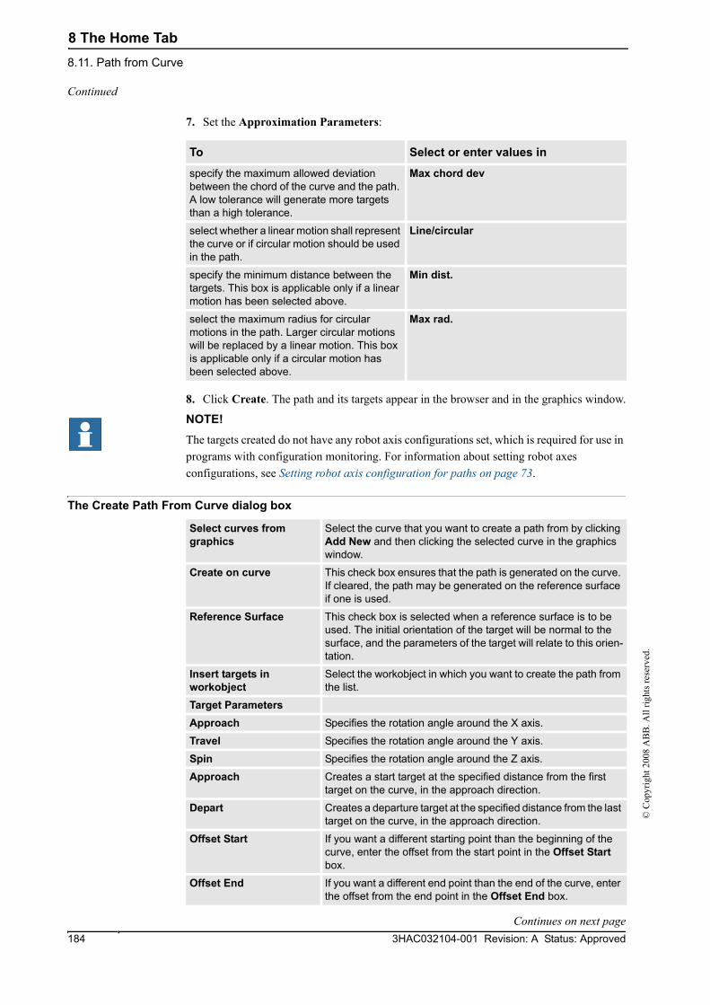
8 The Home Tab8.11. Path from Curve
3HAC032104-001 Revision: A Status: Approved184
© C
opyr
ight
200
8 A
BB
. All
right
s res
erve
d.
7. Set the Approximation Parameters:
8. Click Create. The path and its targets appear in the browser and in the graphics window.
NOTE!The targets created do not have any robot axis configurations set, which is required for use in programs with configuration monitoring. For information about setting robot axes configurations, see Setting robot axis configuration for paths on page 73.
The Create Path From Curve dialog box
To Select or enter values in
specify the maximum allowed deviation between the chord of the curve and the path. A low tolerance will generate more targets than a high tolerance.
Max chord dev
select whether a linear motion shall represent the curve or if circular motion should be used in the path.
Line/circular
specify the minimum distance between the targets. This box is applicable only if a linear motion has been selected above.
Min dist.
select the maximum radius for circular motions in the path. Larger circular motions will be replaced by a linear motion. This box is applicable only if a circular motion has been selected above.
Max rad.
Select curves from graphics
Select the curve that you want to create a path from by clicking Add New and then clicking the selected curve in the graphics window.
Create on curve This check box ensures that the path is generated on the curve. If cleared, the path may be generated on the reference surface if one is used.
Reference Surface This check box is selected when a reference surface is to be used. The initial orientation of the target will be normal to the surface, and the parameters of the target will relate to this orien-tation.
Insert targets in workobject
Select the workobject in which you want to create the path from the list.
Target ParametersApproach Specifies the rotation angle around the X axis.
Travel Specifies the rotation angle around the Y axis.
Spin Specifies the rotation angle around the Z axis.
Approach Creates a start target at the specified distance from the first target on the curve, in the approach direction.
Depart Creates a departure target at the specified distance from the last target on the curve, in the approach direction.
Offset Start If you want a different starting point than the beginning of the curve, enter the offset from the start point in the Offset Start box.
Offset End If you want a different end point than the end of the curve, enter the offset from the end point in the Offset End box.
Continued
Continues on next page

8 The Home Tab8.11. Path from Curve
1853HAC032104-001 Revision: A Status: Approved
© C
opyr
ight
200
8 A
BB
. All
right
s res
erve
d.
Local Target Offset Enter the local target offset to generate the same offset at each target.
Max Chord Dev Specifies the maximum allowed deviation between the chord of the curve and the path. A low tolerance will generate a more accurate path with more targets than a high tolerance.
Linear/circular Selects whether linear segments shall represent the curve or if circular segments should be used in the path.
Min Distance Specifies the minimum distance between the targets. This box is only applicable for linear paths.
Max Rad Specifies the maximum radius for circular movements in the path. Larger circular segments will be replaced by linear segments. This box is applicable only for circular paths.
Continued

8 The Home Tab8.12. Teach Instruction
3HAC032104-001 Revision: A Status: Approved186
© C
opyr
ight
200
8 A
BB
. All
right
s res
erve
d.
8.12. Teach Instruction
Teaching a move instruction1. In the Layout browser, make sure the settings for active robot, workobject, tool, motion
type and path are appropriate for the move instruction to create.
2. Jog the robot to the desired location. If jogging the robot using the freehand mode, you can also use snap modes for snapping its TCP to objects in the station.
3. Click Teach Instruction. A move instruction is now created last in the path.

8 The Home Tab8.13. Move Instruction
1873HAC032104-001 Revision: A Status: Approved
© C
opyr
ight
200
8 A
BB
. All
right
s res
erve
d.
8.13. Move Instruction
Creating a move instruction and a corresponding targetTo create a move instruction, follow these steps:
1. Click Move Instruction to bring up a dialog box.
2. Select the Reference coordinate system for the move instruction.
3. Enter the Position to reach for the move instruction by clicking Add New in the Coordinates box and then click the required to-points in the graphics window. You can also enter the values in the Coordinates boxes and click Add.
4. Enter the Orientation for the move instruction.
5. By clicking the More/Less button, you can expand or collapse the Create Move Instruction dialog box. When the dialog box has been expanded, you can change the Target name and the Work object to which the target (with the move instruction) will belong.
6. Click Create to create the move instruction. The move instruction will appear under the path node as a reference to the target.
The Create Move Instruction dialog box for jointtarget movements
Name Here you can change the name of the target you create when creating the move instruction.
Robot axes Specify the joint values for the robot. Select the box and click the list to set the values.
External axes box Specify the joint values for external axes, if any exist in the station. Select the box and click the list to set the values.
Storage Type Click this button to expand or collapse parts of the create move instruction dialog box.
Module Specify the module in which the jointtarget shall be declared.

8 The Home Tab8.14. Action Instruction
3HAC032104-001 Revision: A Status: Approved188
© C
opyr
ight
200
8 A
BB
. All
right
s res
erve
d.
8.14. Action Instruction
Creating an action instruction1. In the Layout browser, select where to insert the action instruction.
2. Click Action Instruction to bring up a dialog box.
3. From the Instruction Templates list, select the action instruction to create.
4. Optionally, modify instruction arguments in the Instruction Arguments grid. For detailed information about the arguments for each instruction, see the Rapid reference manual.
5. Click Create.
To insert the action instruction Select
at the beginning of a path the path
after another instruction the proceeding instruction

8 The Home Tab8.15. Instruction Template Manager
1893HAC032104-001 Revision: A Status: Approved
© C
opyr
ight
200
8 A
BB
. All
right
s res
erve
d.
8.15. Instruction Template Manager
Importing a template1. Click Import to bring up the Open File dialog box.
2. Select the file to import, and click OK.
Exporting a template1. Select an exportable node in the tree view and click Export to bring up the Save File
dialog box.
2. Click OK.
Validating the templates1. Select a node in the tree view and click Validate.
Any invalidity will be reflected by the icons and ToolTips of the respective node and reported in the Output window.
Overview
xx0600003320
Item Description
1 Buttons for importing, exporting and validating.
2 The instruction template tree. This hierarchal tree set organizes the templates. Templates are always the lowest level nodes. For details about specific nodes in the tree, see item 5 and below.
3 Brief description for editing and creating instruction templates.
4 The Instruction grid. All arguments and settings for the object selected in the tree are displayed here. Only white boxes are editable. Red values indicate that the values are invalid.
Continues on next page
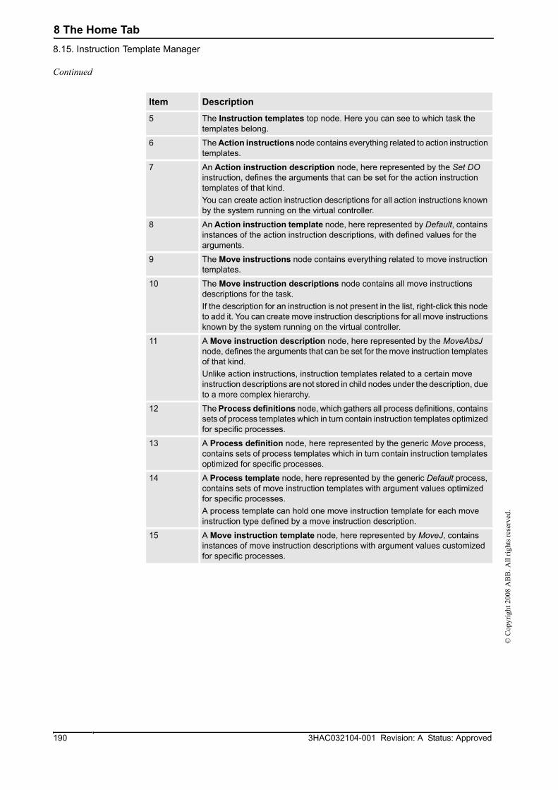
8 The Home Tab8.15. Instruction Template Manager
3HAC032104-001 Revision: A Status: Approved190
© C
opyr
ight
200
8 A
BB
. All
right
s res
erve
d.
5 The Instruction templates top node. Here you can see to which task the templates belong.
6 The Action instructions node contains everything related to action instruction templates.
7 An Action instruction description node, here represented by the Set DO instruction, defines the arguments that can be set for the action instruction templates of that kind. You can create action instruction descriptions for all action instructions known by the system running on the virtual controller.
8 An Action instruction template node, here represented by Default, contains instances of the action instruction descriptions, with defined values for the arguments.
9 The Move instructions node contains everything related to move instruction templates.
10 The Move instruction descriptions node contains all move instructions descriptions for the task. If the description for an instruction is not present in the list, right-click this node to add it. You can create move instruction descriptions for all move instructions known by the system running on the virtual controller.
11 A Move instruction description node, here represented by the MoveAbsJ node, defines the arguments that can be set for the move instruction templates of that kind.Unlike action instructions, instruction templates related to a certain move instruction descriptions are not stored in child nodes under the description, due to a more complex hierarchy.
12 The Process definitions node, which gathers all process definitions, contains sets of process templates which in turn contain instruction templates optimized for specific processes.
13 A Process definition node, here represented by the generic Move process, contains sets of process templates which in turn contain instruction templates optimized for specific processes.
14 A Process template node, here represented by the generic Default process, contains sets of move instruction templates with argument values optimized for specific processes.A process template can hold one move instruction template for each move instruction type defined by a move instruction description.
15 A Move instruction template node, here represented by MoveJ, contains instances of move instruction descriptions with argument values customized for specific processes.
Item Description
Continued

8 The Home Tab8.16.1. Move
1913HAC032104-001 Revision: A Status: Approved
© C
opyr
ight
200
8 A
BB
. All
right
s res
erve
d.
8.16 The Freehand Group
8.16.1. Move
Moving an item1. In the Layout browser, select the item you want to move.
2. Click Move.
3. In the graphics window, click one of the axes and drag the item into position.

8 The Home Tab8.16.2. Rotate
3HAC032104-001 Revision: A Status: Approved192
© C
opyr
ight
200
8 A
BB
. All
right
s res
erve
d.
8.16.2. Rotate
Rotating an item1. In the Layout browser, select the item you want to rotate.
2. Click Rotate.
3. In the graphics window, click one of the rotational rings and drag the item into position.
If you press the ALT key while rotating, the item will snap 10 degrees at a time.

8 The Home Tab8.16.3. Jog Joint
1933HAC032104-001 Revision: A Status: Approved
© C
opyr
ight
200
8 A
BB
. All
right
s res
erve
d.
8.16.3. Jog Joint
Jogging the joints of a robot1. In the Layout browser, select the robot you want to move.
2. Click Jog Joint.
3. Click the joint you want to move and drag it to the preferred position.
If you press the ALT key when jogging the joints of the robot, the robot will move 10 degrees at a time. If you press the f key, the robot will move 0.1 degree at a time.

8 The Home Tab8.16.4. Jog Linear
3HAC032104-001 Revision: A Status: Approved194
© C
opyr
ight
200
8 A
BB
. All
right
s res
erve
d.
8.16.4. Jog Linear
Jogging the TCP of a robot1. In the Layout browser, select the robot you want to move.
2. In the Freehand group, click Jog Linear. A coordinate system will be displayed at the TCP of the robot.
3. Click the axis you want to move and drag the TCP to the preferred position.
If you press the f key while jogging the robot linearly, the robot will move with a smaller step size.

8 The Home Tab8.16.5. MultiRobot Jog
1953HAC032104-001 Revision: A Status: Approved
© C
opyr
ight
200
8 A
BB
. All
right
s res
erve
d.
8.16.5. MultiRobot Jog
Jogging robots in multirobot mode1. In the Freehand group, click MultiRobot Jog. Select the robots to be jogged from the list
of available robots.
2. Select the jogging mode, jog one of the robots and the other ones will follow the movement.

8 The Home Tab8.16.5. MultiRobot Jog
3HAC032104-001 Revision: A Status: Approved196
© C
opyr
ight
200
8 A
BB
. All
right
s res
erve
d.

9 The Modeling Tab9.1. Overview
1973HAC032104-001 Revision: A Status: Approved
© C
opyr
ight
200
8 A
BB
. All
right
s res
erve
d.
9 The Modeling Tab9.1. Overview
The Modeling tabThe Modeling tab contains the controls for creating and grouping components, creating bodies, measurements and CAD operations.

9 The Modeling Tab9.2. Component Group
3HAC032104-001 Revision: A Status: Approved198
© C
opyr
ight
200
8 A
BB
. All
right
s res
erve
d.
9.2. Component Group
Creating a component group1. Click Component Group. The Group node will be displayed in the Layout browser.
2. Click the objects to add to the group. Drag them to the Group node.

9 The Modeling Tab9.3. Empty Part
1993HAC032104-001 Revision: A Status: Approved
© C
opyr
ight
200
8 A
BB
. All
right
s res
erve
d.
9.3. Empty Part
Creating an empty part1. Click Empty Part. The Part node will be displayed in the Layout browser.

9 The Modeling Tab9.4. Solid
3HAC032104-001 Revision: A Status: Approved200
© C
opyr
ight
200
8 A
BB
. All
right
s res
erve
d.
9.4. Solid
Creating a solid1. Click Solid and then click the type of solid you want to create to bring up a dialog box.
2. Enter requested values in in the dialog box and click Create. For detailed information about the specific dialog box for the curve to create, see below:
The Create Box dialog box
xx0600002655
The Create Box from 3-Points dialog box
xx0600002662
Reference Select the Reference coordinate system to which all positions or points will be related.
Corner Point (A) Click in one of these boxes, and then click the corner point in the graphics window to transfer the values to the Corner Point boxes, or type the position. The corner point will be the local origin of the box.
Orientation If the object shall be rotated relative to the reference coordinate system, specify the rotation.
Length (B) Specify the box dimension along its X axis.
Width (C) Specify the box dimension along its Y axis.
Height (D) Specify the box dimension along its Z axis.
A BC
D
Reference Select the Reference coordinate system to which all positions or points will be related.
Corner Point (A) This point will be the local origin of the box.Either type the position, or click in one of the boxes and then select the point in the graphics window.
A
C
B
Continues on next page
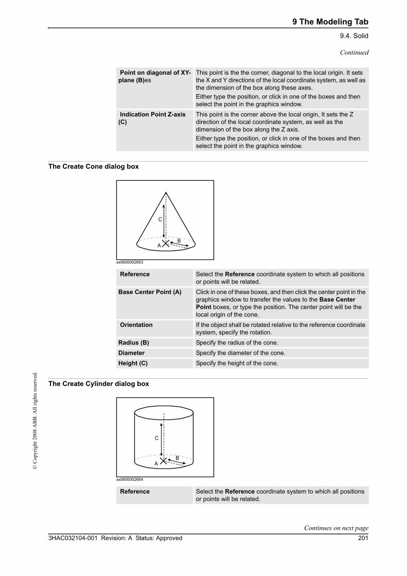
9 The Modeling Tab9.4. Solid
2013HAC032104-001 Revision: A Status: Approved
© C
opyr
ight
200
8 A
BB
. All
right
s res
erve
d.
The Create Cone dialog box
xx0600002663
The Create Cylinder dialog box
xx0600002664
Point on diagonal of XY-plane (B)es
This point is the the corner, diagonal to the local origin. It sets the X and Y directions of the local coordinate system, as well as the dimension of the box along these axes.Either type the position, or click in one of the boxes and then select the point in the graphics window.
Indication Point Z-axis (C)
This point is the corner above the local origin, It sets the Z direction of the local coordinate system, as well as the dimension of the box along the Z axis.Either type the position, or click in one of the boxes and then select the point in the graphics window.
Reference Select the Reference coordinate system to which all positions or points will be related.
Base Center Point (A) Click in one of these boxes, and then click the center point in the graphics window to transfer the values to the Base Center Point boxes, or type the position. The center point will be the local origin of the cone.
Orientation If the object shall be rotated relative to the reference coordinate system, specify the rotation.
Radius (B) Specify the radius of the cone.
Diameter Specify the diameter of the cone.
Height (C) Specify the height of the cone.
AB
C
Reference Select the Reference coordinate system to which all positions or points will be related.
A
C
B
Continued
Continues on next page

9 The Modeling Tab9.4. Solid
3HAC032104-001 Revision: A Status: Approved202
© C
opyr
ight
200
8 A
BB
. All
right
s res
erve
d.
The Create Pyramid dialog box
xx0600002667
The Create Sphere dialog box
xx0600002668
Base Center Point (A) Click in one of these boxes, and then click the center point in the graphics window to transfer the values to the Base Center Point boxes, or type the position. The center point will be the local origin of the cylinder.
Orientation If the object shall be rotated relative to the reference coordinate system, specify the rotation.
Radius (B) Specify the radius of the cylinder.
Diameter Specify the diameter of the cylinder.
Height (C) Specify the height of the cylinder.
Reference Select the Reference coordinate system to which all positions or points will be related.
Base Center Point (A) Click in one of these boxes, and then click the center point in the graphics window to transfer the values to the Base Center Point boxes, or type the position. The center point will be the local origin of the pyramid.
Orientation If the object shall be rotated relative to the reference coordinate system, specify the rotation.
Center to Corner Point (B)
Either type the position, or click in the box and then select the point in the graphics window.
Height (C) Specify the height of the pyramid.
Number of Sides Specify the number of sides of the pyramid. The maximum number of sides is 50.
AB
C
Reference Select the Reference coordinate system to which all positions or points will be related.
B
AB
Continued
Continues on next page
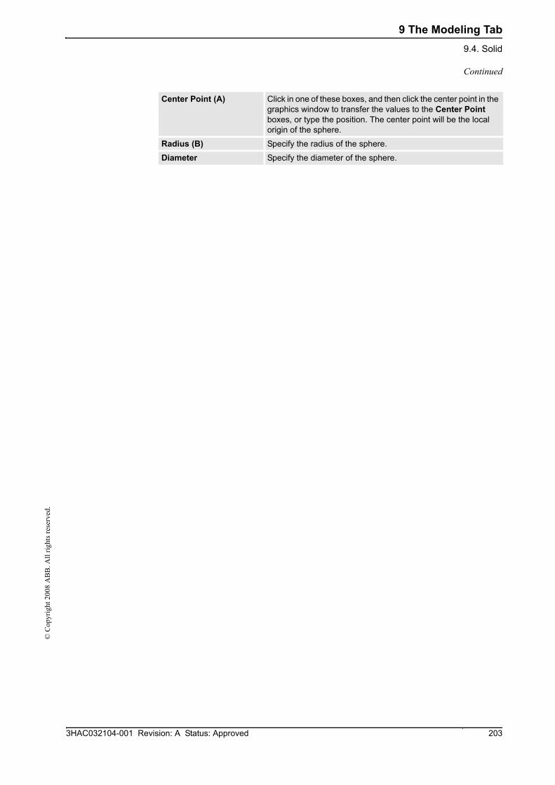
9 The Modeling Tab9.4. Solid
2033HAC032104-001 Revision: A Status: Approved
© C
opyr
ight
200
8 A
BB
. All
right
s res
erve
d.
Center Point (A) Click in one of these boxes, and then click the center point in the graphics window to transfer the values to the Center Point boxes, or type the position. The center point will be the local origin of the sphere.
Radius (B) Specify the radius of the sphere.
Diameter Specify the diameter of the sphere.
Continued

9 The Modeling Tab9.5. Surface
3HAC032104-001 Revision: A Status: Approved204
© C
opyr
ight
200
8 A
BB
. All
right
s res
erve
d.
9.5. Surface
Creating a surface1. Click Surface and then click the type of solid you want to create to bring up a dialog box.
2. Enter requested values in in the dialog box and click Create. For detailed information about the specific dialog box for the curve to create, see below:
The Create Surface Circle dialog box
xx0600002669
The Create Rectangle dialog box
xx0600002671
Reference Select the Reference coordinate system, to which all positions or points will be related.
Center Point (A) Click in one of these boxes, and then click the center point in the graphics window to transfer the values to the Center Point boxes, or type the position. The center point will be the local origin of the circle.
Orientation If the object shall be rotated relative to the reference coordinate system, specify the rotation.
Radius (B) Specify the radius of the circle.
Diameter Specify the diameter of the circle.
AB
Reference Select the Reference coordinate system to which all positions or points will be related.
Start Point (A) Click in one of these boxes, and then click the center point in the graphics window to transfer the values to the Start Point boxes, or type the position. The start point will be the local origin of the rectangle.
Orientation If the object shall be rotated relative the reference coordinate system, specify the rotation.
AB
C
Continues on next page

9 The Modeling Tab9.5. Surface
2053HAC032104-001 Revision: A Status: Approved
© C
opyr
ight
200
8 A
BB
. All
right
s res
erve
d.
The Create Surface Polygon dialog box
xx0600002670
The Create Surface from Curve dialog box
Length (B) Specify the length of the rectangle.
Width (C) Specify the width of the rectangle
Reference Select the Reference coordinate system to which all positions or points will be related.
Center Point Click in one of these boxes, and then click the center point in the graphics window to transfer the values to the Center Point boxes, or type the position. The center point will be the local origin of the polygon.
First Vertex Point Either type the position, or click in one of the boxes and then select the point in the graphics window.
Vertices Specify the number of the vertices here. The maximum number of vertices is 50.
AB
Select Curve from graphics
Select a curve by clicking it in the graphics window.
Continued

9 The Modeling Tab9.6. Curve
3HAC032104-001 Revision: A Status: Approved206
© C
opyr
ight
200
8 A
BB
. All
right
s res
erve
d.
9.6. Curve
Creating a curve1. Click Curve and then click the curve you want to create to bring up a dialog box.
2. Enter requested values in in the dialog box and click Create. For detailed information about the specific dialog box for the curve to create, see below:
The Create Line dialog box
xx0500001513
The Create Circle dialog box
xx0500001512
Reference Select the Reference coordinate system to which all positions or points will be related.
Start point (A) Click in one of these boxes, and then click the start point in the graphics window to transfer the values to the Start Point boxes.
End Point (B) Click in one of these boxes, and then click the end point in the graphics window to transfer the values to the End Point boxes.
Reference Select the Reference coordinate system to which all positions or points will be related.
Center point (A) Click in one of these boxes, and then click the center point in the graphics window to transfer the values to the Center Point boxes.
Orientation Specify the orientation coordinates for the circle.
Radius (A-B) Specify the radius of the circle.
Diameter Alternatively, specify the diameter.
Continues on next page

9 The Modeling Tab9.6. Curve
2073HAC032104-001 Revision: A Status: Approved
© C
opyr
ight
200
8 A
BB
. All
right
s res
erve
d.
The Create Three Points Circle dialog box
xx0500001518
The Create Arc dialog box
xx0500001520
Reference Select the Reference coordinate system to which all positions or points will be related.
First Point (A) Click in one of these boxes, and then click the first point in the graphics window to transfer the values to the First Point boxes.
Second Point (B) Click in one of these boxes, and then click the second point in the graphics window to transfer the values to the Second Point boxes.
Third Point (C) Click in one of these boxes, and then click the third point in the graphics window to transfer the values to the Third Point boxes.
Reference Select the Reference coordinate system to which all positions or points will be related.
Start Point (A) Click in one of these boxes, and then click the start point in the graphics window to transfer the values to the Start Point boxes.
Mid Point (B) Click in one of these boxes, and then click the second point in the graphics window to transfer the values to the Mid Point boxes.
End Point (C) Click in one of these boxes, and then click the end point in the graphics window to transfer the values to the End Point boxes.
Continued
Continues on next page
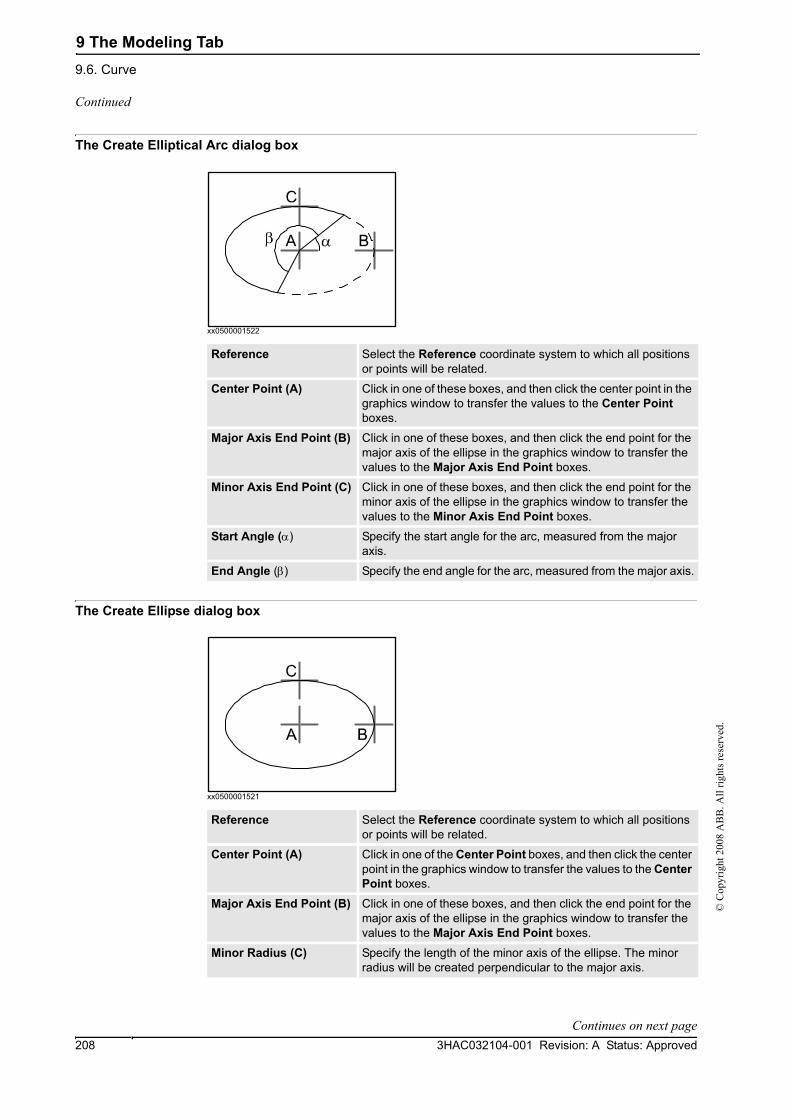
9 The Modeling Tab9.6. Curve
3HAC032104-001 Revision: A Status: Approved208
© C
opyr
ight
200
8 A
BB
. All
right
s res
erve
d.
The Create Elliptical Arc dialog box
xx0500001522
The Create Ellipse dialog box
xx0500001521
Reference Select the Reference coordinate system to which all positions or points will be related.
Center Point (A) Click in one of these boxes, and then click the center point in the graphics window to transfer the values to the Center Point boxes.
Major Axis End Point (B) Click in one of these boxes, and then click the end point for the major axis of the ellipse in the graphics window to transfer the values to the Major Axis End Point boxes.
Minor Axis End Point (C) Click in one of these boxes, and then click the end point for the minor axis of the ellipse in the graphics window to transfer the values to the Minor Axis End Point boxes.
Start Angle (α) Specify the start angle for the arc, measured from the major axis.
End Angle (β) Specify the end angle for the arc, measured from the major axis.
Reference Select the Reference coordinate system to which all positions or points will be related.
Center Point (A) Click in one of the Center Point boxes, and then click the center point in the graphics window to transfer the values to the Center Point boxes.
Major Axis End Point (B) Click in one of these boxes, and then click the end point for the major axis of the ellipse in the graphics window to transfer the values to the Major Axis End Point boxes.
Minor Radius (C) Specify the length of the minor axis of the ellipse. The minor radius will be created perpendicular to the major axis.
Continued
Continues on next page

9 The Modeling Tab9.6. Curve
2093HAC032104-001 Revision: A Status: Approved
© C
opyr
ight
200
8 A
BB
. All
right
s res
erve
d.
The Create Rectangle dialog box
xx0500001516
The Create Polygon dialog box
xx0500001514
Reference Select the Reference coordinate system to which all positions or points will be related.
Start Point (A) Click in one of these boxes, and then click the start point in the graphics window to transfer the values to the Start Point boxes. The rectangle will be created in the positive coordinate directions.
Orientation Specify the orientation coordinates for the rectangle.
Length (B) Specify the length of the rectangle along the x axis.
Width (C) Specify the width of the rectangle along the y axis.
Reference Select the Reference coordinate system to which all positions or points will be related.
Center Point (A) Click in one of these boxes, and then click the center point in the graphics window to transfer the values to the Center Point boxes.
First Vertex Point (B) Click in one of these boxes, and then click the first vertex point in the graphics window to transfer the values to the First Vertex Point boxes. The distance between the center point and the first vertex point will be used for all vertex points.
Vertices Specify the number of points to be used when creating the polygon. The maximum number of vertices is 50.
Continued
Continues on next page

9 The Modeling Tab9.6. Curve
3HAC032104-001 Revision: A Status: Approved210
© C
opyr
ight
200
8 A
BB
. All
right
s res
erve
d.
The Create Polyline dialog box
xx0500001515
The Create Spline dialog box
xx0500001517
Reference Select the Reference coordinate system to which all positions or points will be related.
Point Coordinates Specify each node of the polyline here, one at a time, by either typing the values, or by clicking in one of these boxes, and then selecting the point in the graphics window to transfer its coordi-nates.
Add Click this button to add a point and its coordinates to the list.
Modify Click this button to modify an already defined point, after you have selected it in the list and entered new values.
List The nodes of the polyline. To add more nodes, click Add New, click the desired point in the graphics window, and then click Add.
Reference Select the Reference coordinate system to which all positions or points will be related.
Point Coordinates Specify each node of the spline here, one at a time, by either typing the values, or by clicking in one of these boxes, and then selecting the point in the graphics window to transfer its coordi-nates.
Ad Click this button to add a point and its coordinates to the list.
Modify Click this button to modify an already defined point, after you have selected it in the list and entered new values.
List This nodes of the spline. To add more nodes, click Add New, click the desired point in the graphics window, and then click Add.
Continued

9 The Modeling Tab9.7. Border
2113HAC032104-001 Revision: A Status: Approved
© C
opyr
ight
200
8 A
BB
. All
right
s res
erve
d.
9.7. Border
Creating a curve1. Click Border and then click the border you want to create to bring up a dialog box.
2. Enter requested values in in the dialog box and click Create. For detailed information about the specific dialog box for the border to create, see below:
The Create Border Between Bodies dialog boxTo use the create border between bodies command, the station must contain at least two objects.
xx0500001524
The Create Border Around Surface dialog boxTo use the create border around surface command, the station must contain at least one object with a graphical representation.
xx0500001523
First Body Click in this box and then select the first body in the graphics window.
Second Body Click in this box and then select the second body in the graphics window.
Select Surface Click in this box and then select a surface in the graphics window.
Continues on next page

9 The Modeling Tab9.7. Border
3HAC032104-001 Revision: A Status: Approved212
© C
opyr
ight
200
8 A
BB
. All
right
s res
erve
d.
The Create Border From Points dialog boxTo use the create border from points command, the station must contain at least one object.
en0500001531
Selected Object Click in this box and then select an object in the graphics window.
Point Coordinates Specify the points that define the border here, one at a time, by either typing the values, or by clicking in one of these boxes, and then selecting the point in the graphics window to transfer its coordinates.
Add Click this button to add a point and its coordinates to the list.
Modify Click this button to modify an already defined point, after you have selected it in the list and entered new values.
List The points that define the borders. To add more points, click Add New, click the desired point in the graphics window, and then click Add.
Continued

9 The Modeling Tab9.8. Intersect
2133HAC032104-001 Revision: A Status: Approved
© C
opyr
ight
200
8 A
BB
. All
right
s res
erve
d.
9.8. Intersect
The Intersect dialog box
xx0600002673
Keep Original Select this check box to keep the original bodies when creating the new body.
Intersect... (A) Select the body from which you want to make an intersection (A) by clicking it in the graphics window.
...and (B) Select the body with which you want to make an intersection (B) by clicking it in the graphics window. A new body will be created based on the common area between the selected bodies A and B.
A B
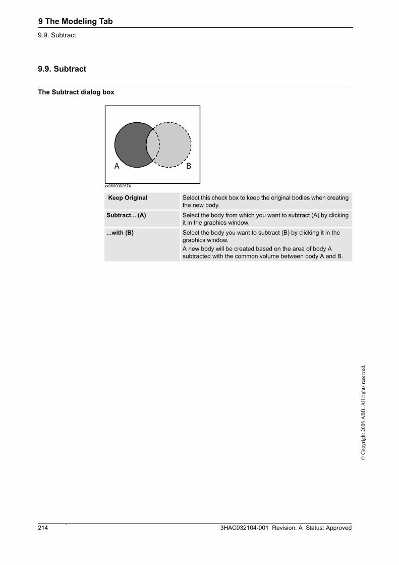
9 The Modeling Tab9.9. Subtract
3HAC032104-001 Revision: A Status: Approved214
© C
opyr
ight
200
8 A
BB
. All
right
s res
erve
d.
9.9. Subtract
The Subtract dialog box
xx0600002674
Keep Original Select this check box to keep the original bodies when creating the new body.
Subtract... (A) Select the body from which you want to subtract (A) by clicking it in the graphics window.
...with (B) Select the body you want to subtract (B) by clicking it in the graphics window. A new body will be created based on the area of body A subtracted with the common volume between body A and B.
A B

9 The Modeling Tab9.10. Union
2153HAC032104-001 Revision: A Status: Approved
© C
opyr
ight
200
8 A
BB
. All
right
s res
erve
d.
9.10. Union
The Union dialog box
xx0600002672
Keep Original Select this check box to keep the original bodies when creating the new body.
Union... (A) Select the body that you want to unify (A) by clicking it in the graphics window.
...and (B) Select the body that you want to unify (B) by clicking it in the graphics window. A new body will be created based on the areas of the two selected bodies A and B.
A B

9 The Modeling Tab9.11. Extrude Surface or Curve
3HAC032104-001 Revision: A Status: Approved216
© C
opyr
ight
200
8 A
BB
. All
right
s res
erve
d.
9.11. Extrude Surface or Curve
Extruding a surface or curve1. From the selection level toolbar, select Surface or Curve, as appropriate.
2. In the graphics window, select the surface or curve you wish to extrude. Click Extrude Surface or Extrude Curve, as appropriate. The Extrude Surface or Curve dialog box opens below the Modeling browser.
3. For extrusion along a vector, fill in the values.
For extrusion along a curve, select the Extrude Along Curve option. Click the Curve box, and select the curve in the Graphics window.
4. If you wish the form to appear as a surface model, clear the Make Solid check box.
5. Click Create.
The Extrude Surface or Curve dialog box
Surface or Curve Denotes the surface or curve to be extruded.To select the surface or curve, first click in the box, then select the surface or curve in the graphics window.
Extrude Along Vector Enables extrusion along a specified vector.
From Point (mm) The start point of the vector.
To Point (mm) The end point of the vector.
Extrude Along Curve Enables extrusion along a specified curve.
Curve Denotes the curve used as a sweep path.
xx0600003076
To select the curve, first click the box, then the curve in the graphics window.
Make Solid Select this check box to convert the extruded form into a solid.

9 The Modeling Tab9.12. Line from Normal
2173HAC032104-001 Revision: A Status: Approved
© C
opyr
ight
200
8 A
BB
. All
right
s res
erve
d.
9.12. Line from Normal
Creating a line from normal1. Click Surface Selection.
2. Click Line to Normal to bring up a dialog box.
3. Click on a face to select it in the Select Face box.
4. In the Length box, specify a length for the line.
5. Optionally, select the Invert Normal check box to invert the direction of the line.
6. Click Create.

9 The Modeling Tab9.13. The Measure Group
3HAC032104-001 Revision: A Status: Approved218
© C
opyr
ight
200
8 A
BB
. All
right
s res
erve
d.
9.13. The Measure Group
TIP!Make sure to select the appropriate snap mode and selection levels before making your measurements.
Measuring distances or angles1. Click the type of measurement you want to use:
The mouse pointer will turn into a ruler when you have activated any of the measurement functions.
2. In the graphics window, select the points or objects to measure between. Information about the measuring points is displayed in the Output window.
The results will be displayed in the Measurements tab in the Output window when all points have been selected.
3. Optionally, repeat step 3 for making a new measurement of the same type.
TIP!You can also activate and deactivate the measurement functions from the measurement toolbar.
To measure the Select
distance between two points you select in the graphics window. Point to pointangle defined by three points you select in the graphics window. The first point to select is the converging point, thereafter you shall select one point on each line.
Angle
diameter, with the circle defined by three points you select from the graphics window.
Diameter
closest distance between two objects you select in the graphics window.
Minimum distance

9 The Modeling Tab9.14. Create Mechanism
2193HAC032104-001 Revision: A Status: Approved
© C
opyr
ight
200
8 A
BB
. All
right
s res
erve
d.
9.14. Create Mechanism
Create a new mechanism1. Click Create Mechanism.
The Mechanism Modeler opens in create mode.
2. In the Mechanism Model Name box, enter a mechanism name.
3. From the Mechanism Type list, select a mechanism type.
4. In the tree structure, right-click Links, and then click Add Link to bring up the Create Link dialog box.
A suggested name appears in the Link Name box.
5. In the Selected Part list, select a part (which will be highlighted in the graphics window) and click the arrow button to add the part to the Parts list box.
The Selected Part list then automatically selects the next part, if any more are available. Add these, as required.
6. Select a part in the Parts list box, enter any values in the Selected Parts group boxes, and then click Apply to Part.
Repeat for each part, as required.
7. Click OK.
8. In the tree structure, right-click Joints, and then click Add Joint to bring up the Create Joint dialog box.
A suggested name appears in the Joint Name box.
9. Complete the Create Joint dialog box, and then click OK.
10. In the tree structure, right-click Frame/Tool Data, and then click Add Frame/Tool to bring up the Create Frame/Tool dialog box.
A suggested name appears in the Frame/Tool Data name box.
11. Complete the Create Frame/Tool dialog box, and then click OK.
The validity criteria for the Frame/Tool node are as follows:
12. In the tree structure, right-click Calibration, and then click Add Calibration to bring up the Create Calibration dialog box.
13. Complete the Create Calibration dialog box, and then click OK.
14. In the tree structure, right-click Dependency, and then click Add Dependency to bring up the Create Dependency dialog box.
15. Complete the Create Dependency dialog box, and then click OK.
16. If all nodes are valid, compile the mechanism, see below.
Continues on next page

9 The Modeling Tab9.14. Create Mechanism
3HAC032104-001 Revision: A Status: Approved220
© C
opyr
ight
200
8 A
BB
. All
right
s res
erve
d.
Compiling a mechanismWhen compiling, a new mechanism, created in the create mode of the Mechanism Modeler, is added to the station with the default name "Mechanism_" followed by an index number.
When compiling, an existing editable mechanism, modified in the modify mode of the Mechanism Modeler, is saved without any poses, joint mapping ot transition times.
To compile a mechanism, follow these steps:
1. To compile a new or edited mechanism, click Compile Mechanism.
The mechanism is inserted into the active station. The link parts are cloned with new names, but the corresponding links will update their part references. When the Mechanism modeler is closed, these cloned parts will be removed.
2. The Mechanism Modeler now switches to modify mode. To complete the mechanism, see below.
Completing or modifying a mechanismTo complete the modeling of a mechanism, follow these steps:
1. If the values in the Joint Mapping group are correct, click Set.
2. Configure the Poses grid. To add a pose, click Add and then complete the Create Pose dialog box. Click Apply, followed by OK.
To add a pose, click Add and then complete the Create Pose dialog box. Click Apply, followed by OK.
To edit a pose, select it in the grid, click Edit, and then complete the Modify Pose dialog box. Click OK.
To remove a pose, select it in the grid and then click Remove.
3. Click Edit Transition Times to edit transition times.
4. Click Close.
The Create Mechanism dialog box
The Create/Modify Link dialog boxA link is a moving component of a mechanism. Selecting a link node will highlight it in the graphics window.
Mechanism Model Name Specifies the model name of the mechanism.
Mechanism Type Specifies the mechanism type.
Tree structure The components of the mechanism in a tree structure. The tree structure will not be visible unless the mechanism is editable. Each node (link, joint, frame, calibration and dependency) can be edited in its own dialog box, see below.
Compile Mechanism Click this button to compile the mechanism. This button will not be visible unless the mechanism is editable and the mechanism model name is valid.
Link Name Specifies the name of the link.
Selected Part Specifies the parts to add to the Part list box.
Continued
Continues on next page

9 The Modeling Tab9.14. Create Mechanism
2213HAC032104-001 Revision: A Status: Approved
© C
opyr
ight
200
8 A
BB
. All
right
s res
erve
d.
The Create/Modify Joint dialog boxA joint is the axis where two links move in relation to each other, rotationally or prismatically. Selecting a joint node will display a yellow-green line in the graphics window.
Set as BaseLink The BaseLink is where the kinematical chain begins. This must be the parent of the first joint. A mechanism may have only one BaseLink.
xx0600003086
Adds a selected part to the Part list box.
Remove Part Click this button to remove a selected part from the Part list box.
Selected Part This group manipulates the transform of the selected part.
Part Position Specify the position of the part.
Part Orientation Specify the orientation of the part.
Apply to Part Click this button to apply the settings to the part.
Joint Name Specifies the name of the joint.
Joint Type. Specifies the joint type. The default option is Rotational. Changing the Joint Type clears the Joint Limits below.
Parent Link Specifies the parent link, usually the first joint of the mechanism.
Child Link Specifies the child link. To be valid, the parent and child links may not be identical to each other, and the pair must be unique.
Active Select this check box to make the joint active. An active joint is one that a user can move, while an inactive joint is a slave to an active joint.
Joint Axis This group specifies the axis around or along which the child moves.
First Position Specify the start point of the axis vector.
Second Position Specify the end point of the axis vector.
Jog Axis Demonstrates how the child link moves along its axis.
Limit Type Specifies the limits in each direction to which a joint may move. The options are Constant, Variable and No.
Joint Limits This group is visible in Constant or Variable mode.
Min Limit Specifies the minimum joint limit.
Max Limit Specifies the maximum joint limit.
Joint Limits This group is visible in Constant or Variable mode.
Continued
Continues on next page

9 The Modeling Tab9.14. Create Mechanism
3HAC032104-001 Revision: A Status: Approved222
© C
opyr
ight
200
8 A
BB
. All
right
s res
erve
d.
The Modify Frame/Tool Data dialog boxA frame/tool data node determines the link and location of a frame.
The Create Calibration dialog boxA calibration contains transforms for calibrating the joints. Two calibrations cannot share the same joint.
The Create Dependency dialog boxA dependency is a relationship between two joints, by either a factor or a complex formula.
Variable Limits In Variable mode, variable limit points may be added as an advanced way of delimiting the area of movement.
xx0600003106
xx0600003086
Adds a selected point to the Point list box.
Remove Click this button to remove a selected point from the Point list box.
Frame/Tool Data name Specifies the name of the frame or tool data.
Belongs to Link Specifies the link to which the frame or tool belongs.
Position Specify the position of the transform.
Orientation Specify the orientation of the transform.
Select values from target/Frame
Select this box to select the values from a target or frame, which is selected in the box beneath the check box.
Tool Data This group is visible if the mechanism is a tool.
Mass Specifies the mass of the tool.
Center of Gravity Specify the center of gravity of the tool.
Moment of Inertia lx, ly, lz Specify the moment of inertia of the tool.
Calibration belongs to Joint
Specifies the joint to be calibrated.
Position Specify the position of the transform.
Orientation Specify the orientation of the transform.
Joint Specifies the joint whose motion will be controlled by other joints.
Continued
Continues on next page

9 The Modeling Tab9.14. Create Mechanism
2233HAC032104-001 Revision: A Status: Approved
© C
opyr
ight
200
8 A
BB
. All
right
s res
erve
d.
The Modify Mechanism dialog boxThe Modify Mechanism dialog box contains the objects found in the Create mechanism dialog box, as well as the following:
The Create/Modify Pose dialog box
The Set Transition Times dialog boxThe Set Transition Times dialog box is designed like a distance table in a road atlas. The default values are zero.
Use LeadJoint and factor Select this option to specify a lead joint and factor.
LeadJoint Specifies the lead joint.
Factor This list holds a double which denotes the extent to which the lead joint will control the main joint.
Use Formula Select this option to enter a formula in the box.
Joint Mapping These boxes handle the joint mapping of the mechanism. When editing, the mechanism must be disconnected from its library.The values must be integers from 1 – 6 in ascending order.
Set Click this button to set the joint mapping.
Poses Displays the poses and their joint values.Selecting a pose will move the mechanism to it in the graphics window.
Add Click this button to bring up the Create Pose dialog box for adding a pose.
Edit Click this button to bring up the Modify Pose dialog box for editing a selected pose.A SyncPose cannot be edited unless the mechanism is discon-nected from its library.
Remove Click this button to remove the selected pose.A single SyncPose cannot be removed.
Set Transition Times Click this button to edit the transition times.
Pose Name Specifies the name of the pose. If the pose is a SyncPose, this box is not editable.The names "HomePosition" and "SyncPosition" are disallowed.
Home Pose Select this box to specify the home pose of the mechanism. If selected, the non-editable pose name will be "HomePose".
Launch Joint Jog Tool Click this button to bring up the joint jog tool.
Use Current Click this button to set the current joint values in the Joint Values group.
Reset Values Click this button to reset the joint values in the Joint Values group to what they were when the dialog box was opened.
Joint Values Specify the joint values of the pose.
From Pose Specifies the start of the transition for the named pose.
To Pose Specifies the end of the transition for the named pose.
Continued

9 The Modeling Tab9.15. Create Tool
3HAC032104-001 Revision: A Status: Approved224
© C
opyr
ight
200
8 A
BB
. All
right
s res
erve
d.
9.15. Create Tool
Creating a toolYou can create a robot hold tool by using the Create Tool Wizard. The wizard allows you to easily create a tool from an existing part or by using a dummy part to represent a tool. To create a tool complete with tooldata, follow these steps:
1. Click Create Tool.
2. In the Tool Name box, enter a tool name and choose one of the following options:
3. Continue entering the Mass of the tool, the Center of Gravity and the Moment of Inertia Ix, Iy, Iz, if these values are known. If you do not know the correct values, the tool can still be used for programing motions, but this data must be corrected before running the program on real robots or measuting cycle times.
Tip! If the tool is built from materials with a similar density, you can find the center of gravity by clicking the tool model using the Center of gravity snap mode.
4. Click Next to go the next page of the wizard.
5. In the TCP Name box, enter a name for the Tool Center Point (TCP). The default name is the same as the name of the tool. If creating several TCPs for one tool, each TCP must have a unique name.
6. Enter the position of the TCP relative to the world coordinate system, which represents the tool mounting point, by any of the methods below:
7. Click the arrow right button to transfer the values to the TCP(s): box.
If the tool shall have several TCPs, repeat steps 5 to 7 for each TCP.
8. Click Done. The tool will be created and appear in the Objects browser and in the graphics window.
Creating tooldata for an existing geometryTo create tooldata for an existing geometry, follow these steps:
1. Make sure the robot in which to create the tooldata is selected.
2. Click Create Tool and select Use Existing and the imported tool from the list.
Option Action
Use Existing Select one of the existing parts from the list. The selected part will represent the tool graphics.The selected part must be a single part. Parts with attache-ments cannot be selected.
Use Dummy A cone will be created to represent the tool.
Method Description
Read values from existing target or frame
Click in the Values from Target/Frame box, then select the frame either in the graphics window or the Paths&Targets browser.
Enter position and orientation manually.
In the Position and Orientation boxes, type the values.NOTE: If Use Dummy Part is selected, the position value can not be 0,0,0. At least one coordinate has to be > 0 in order for a cone to be created.
Continues on next page
9 The Modeling Tab9.15. Create Tool
2253HAC032104-001 Revision: A Status: Approved
© C
opyr
ight
200
8 A
BB
. All
right
s res
erve
d.
3. Enter the requested data in the boxes in the Create Tool Wizard.
4. Attach the tool by dragging it to the robot.
What to do nextTo make the tool ready to use, do one of the following:
• To make the robot hold the tool, attach the tool to the robot.
• In the graphics window, check the position and orientation of the TCP. If it is incorrect, modify the values in the tool frame part of the tooldata.
• To simplify future usage of the created tool, save it as a library. On the File menu, click Save As Library. Browse to the folder where you want to store the tool component, enter a name for the tool component and click Save.
Continued

9 The Modeling Tab9.15. Create Tool
3HAC032104-001 Revision: A Status: Approved226
© C
opyr
ight
200
8 A
BB
. All
right
s res
erve
d.

10 The Simulation Tab10.1. Overview
2273HAC032104-001 Revision: A Status: Approved
© C
opyr
ight
200
8 A
BB
. All
right
s res
erve
d.
10 The Simulation Tab10.1. Overview
The Simulation tabThe Simulation tab contains the controls for setting up, configuring, controlling, monitoring and recording simulations.

10 The Simulation Tab10.2. Create Collision Set
3HAC032104-001 Revision: A Status: Approved228
© C
opyr
ight
200
8 A
BB
. All
right
s res
erve
d.
10.2. Create Collision Set
OverviewA collision set contains two groups, Objects A and Objects B, in which you place the objects to detect any collisions between them. When any object in Objects A collides with any object in Objects B, the collision is displayed in the graphical view and logged in the output window. You can have several collision sets in the station, but each collision set can only contain two groups.
Creating a collision set1. Click Create Collision Set to create a collision set in the Layout browser.
2. Expand the collision set and then drag one of the objects to the ObjectsA node to check for collisions.
If you have several objects you want to check for collisions with objects in the ObjectsB node, for example, the tool and the robot, drag all of them to the ObjectsA node.
3. Drag the objects to the ObjectsB node to check for collisions.
If you have several objects you want to check for collisions with objects in the ObjectsA node, for example, the work piece and the fixture, drag all of them to he ObjectsB node.

10 The Simulation Tab10.3. Simulation Setup
2293HAC032104-001 Revision: A Status: Approved
© C
opyr
ight
200
8 A
BB
. All
right
s res
erve
d.
10.3. Simulation Setup
PrerequisitesTo set up a simulation, the following conditions must be met:
• At least one path must have been created in the station.
• The paths to be simulated must have been synchronized to the virtual controller.
Setting up a simulation1. Click Simulation Setup to bring up a dialog box.
2. In the Select Active Tasks box, select the tasks to be active in the simulation.
3. If a single controller has been selected, select either the Continuous or Single Cycle option.
4. From the Available Procedures list, transfer the procedures to be active in the simulation to the Main Sequence lists by selecting them and clicking the left arrow button between the lists. (This creates a procedure call in the main procedure).
5. To start the simulation from another procedure than the actual Main procedure (that is, to set a temporary Main procedure instead of overwriting the current one), click Select entry point and then specify the procedure to use as Main.
6. Click Apply to set the simulation. If you click OK, the simulation will be set and the dialog box will be closed.
NOTE!If the simulation uses events or involves several different controllers, the virtual time mode Time Slice shall be used to make sure that the timing between the controllers is simulated correctly. For more information about virtual time modes, see Simulation Overview on page 103.
The Setup Simulation dialog box
Select Active Tasks Select the tasks to be active in the simulation.
The Run Mode options Select the run mode when a single controller is selected. The options are Continuous and Single Cycle.
Main Sequence Displays the procedures that will be run when you play the simulation.
<- Click the arrow left button to transfer the selected procedure to the Main Sequence box.
X Click this button to remove the selected procedures or sequences from the Main sequence box.
arrow up Click the arrow up button to move the sequence up in the list in the Main Sequence box or in the Available Procedures box.
arrow down Click the arrow down button to move the sequence down in the list in the Main Sequence box or in the Available Procedures box.
Available Procedures Displays all procedures available in the controller.
Select entry point Click this button to set up several simulations at the same time. In the dialog box, enter a new name for the main procedure, and select the procedures to be included in the new simulation. Click OK.
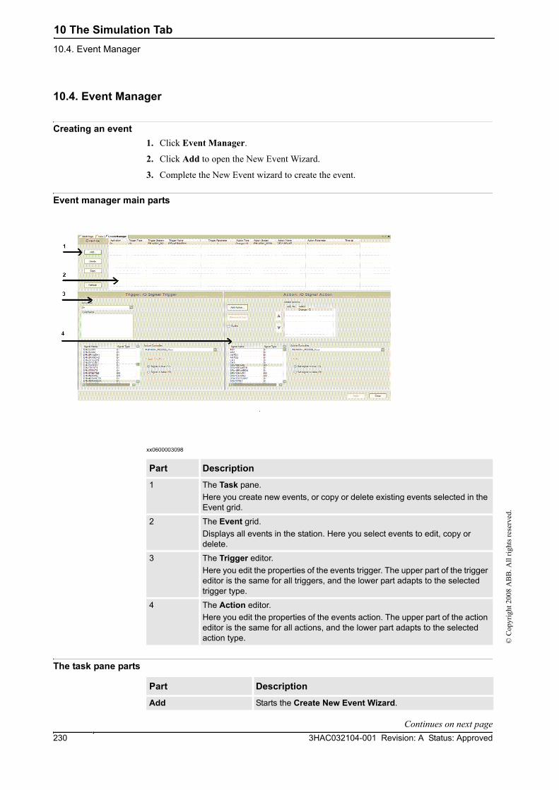
10 The Simulation Tab10.4. Event Manager
3HAC032104-001 Revision: A Status: Approved230
© C
opyr
ight
200
8 A
BB
. All
right
s res
erve
d.
10.4. Event Manager
Creating an event1. Click Event Manager.
2. Click Add to open the New Event Wizard.
3. Complete the New Event wizard to create the event.
Event manager main parts
xx0600003098
The task pane parts
Part Description
1 The Task pane.Here you create new events, or copy or delete existing events selected in the Event grid.
2 The Event grid.Displays all events in the station. Here you select events to edit, copy or delete.
3 The Trigger editor.Here you edit the properties of the events trigger. The upper part of the trigger editor is the same for all triggers, and the lower part adapts to the selected trigger type.
4 The Action editor.Here you edit the properties of the events action. The upper part of the action editor is the same for all actions, and the lower part adapts to the selected action type.
Part Description
Add Starts the Create New Event Wizard.
Continues on next page

10 The Simulation Tab10.4. Event Manager
2313HAC032104-001 Revision: A Status: Approved
© C
opyr
ight
200
8 A
BB
. All
right
s res
erve
d.
The event grid columnsIn the event grid, each row is a an event and the columns in the grid display their properties.:
Delete Deletes the event selected in the Event grid.
Copy Copies the event selected in the Event grid.
Refresh Refreshes the Event manager.
Part Description
Column Description
Activation Displays whether the event is active or not.On = The action is always carried out when the trigger event occurs.Simulation = The action is only carried out if the trigger event occurs when running a simulation.Off = The action is not carried out when the trigger event occurs.
Trigger Type Displays the type of condition that triggers the action.I/O Signal Trigger = Changes a digital I/O signal.I/O Connection = Simulates the behavior of a Programmable Logic Controller (PLC).Collision Trigger = Starts or ends a collision or near-miss between objects in a collision set.The trigger type cannot be changed in the trigger editor. If you want another trigger type than the current one, create a completely new event.
Trigger System When the trigger type is I/O Signal Trigger, this column displays to which system the signal used as trigger belongs.A dash (-) signifies a virtual signal.
Trigger Name The name of the signal or collision set used as trigger.
Trigger Parameter Displays the condition of the event under which triggering occurs.0 = The I/O signal used as trigger switches to false.1 = The I/O signal used as trigger switches to true.Started = A collision starts within the collision set used as trigger.Ended = A collision ends within the collision set used as trigger.Near miss started = A near-miss starts within the collision set used as trigger.Near miss ended = A near-miss ends within the collision set used as trigger.
Continued
Continues on next page

10 The Simulation Tab10.4. Event Manager
3HAC032104-001 Revision: A Status: Approved232
© C
opyr
ight
200
8 A
BB
. All
right
s res
erve
d.
Action Type Displays the action type that occurs in conjunction with the triggerI/O Signal Action = Changes the value of a digital input or output signal.Attach Object = Attaches an object to another.Detach Object = Detaches an object from another.Turn On/Off Simulation Monitor = Toggles the simulation monitor of a specific mechanism.Turn On/Off Timer = Toggles the process timer.Move Mechanism to Pose = Moves the selected mechanism to a predefined pose and thereafter sends a station signal. Activates or deactivates the process timer.Move Graphical Object = Moves a graphical object to a new position and orientation.Show/Hide Graphical Object = Shows or hides the graphical object.Do Nothing = No action occurs.Multiple = The event triggers multiple actions, either all at once or one at a time, each time the trigger is activated. Each action can be viewed in the action editor.
Action System When the action type is Change I/O, this column displays the system to which the signal to change belongs.A dash (-) signifies a virtual signal.
Action Name Displays the name of the signal to change, when the action type is Change I/O.
Action Parameter Displays the condition after the action has occurred.0 = The I/O signal will be set to false.1 = The I/O signal will be set to true.On = Turns the process timer on.Off = Turns the process timer off.Object1 -> Object2 = Displays the object to which another will be attached when the action type is Attach object.Object1 <- Object2 = Displays the object from which another will be detached when the action type is Detach object.Ended = A collision ends within the collision set used as trigger.Near miss started = A near-miss starts within the collision set used as trigger.Near miss ended = A near-miss ends within the collision set used as trigger.Multiple = Signifies multiple actions.
Time Displays the time when the event trigger was executed.
Column Description
Continued
Continues on next page

10 The Simulation Tab10.4. Event Manager
2333HAC032104-001 Revision: A Status: Approved
© C
opyr
ight
200
8 A
BB
. All
right
s res
erve
d.
The trigger editor partsIn the trigger editor you set the properties of the trigger. The upper part of the editor is common for all types of triggers, and the lower part adapts to the trigger type at hand.
Parts common to triggers
Parts specific to I/O signal triggers
Parts specific to I/O connection triggers
Parts specific to Collision triggers
Part Description
Activation Sets whether the event is active or not.On = The action is always carried out when the trigger event occurs.Simulation = The action is only carried out if the trigger event occurs when running a simulation.Off = The action is not carried out when the trigger event occurs.
Comment Text box for comments and notes about the event.
Part Description
Active Controller Select the system to which the I/O to use as a trigger belongs.
Signals Displays all signals that can be used as triggers.
Trigger Condition For digital signals, sets whether the event shall trigger when the signals are set as true or false.For analog signals, which are only available for station signals, the event shall trigger under any of the following conditions: Greater than, Greater/Equal, Less than, Less/Equal, Equal to, Not equal to.
Part Description
Add Opens a dialog box for adding an activator signal to the Activator Signals pane.
Remove Removes a selected activator signal.
Add > Opens a dialog box for adding an operator symbol to the Connections pane.
Remove Removes a selected operator symbol.
Delay (s) Specifies the delay in seconds.
Part Description
Collision Type Set the kind of collision to use as trigger.Started = Triggers when a collision starts.Ended = Triggers when a collision ends.Near miss started =Triggers when a near-miss starts.Near miss ended = Triggers when a near-miss ends.
Collision set Select the collision set to use as trigger.
Continued
Continues on next page

10 The Simulation Tab10.4. Event Manager
3HAC032104-001 Revision: A Status: Approved234
© C
opyr
ight
200
8 A
BB
. All
right
s res
erve
d.
The action editor partsIn the action editor you set the properties of the actions for the event. The upper part of the editor is common to all types of actions, and the lower part adjusts to the selected action.
Parts common to all actions
Parts specific to I/O Actions
Parts specific to Attach actions
Part Description
Add Action Adds a new action that occurs when the triggering condition fulfills. You can add several different actions that either are performed at once or one at a time each time the event triggers. The following types of actions are available:Change I/O = Changes the value of a digital input or output signal.Attach object = Attaches an object to another.Detach object = Detaches and object from another.Turn On/Off Timer = Activates or deactivates the process timer.Do Nothing = No action occurs (might be useful for manipulat-ing sequences of actions).
Remove Action Removes the action selected in the Added Actions list.
Cyclic When selected, the actions are performed one at a time each time the trigger occurs. When all actions in the list have been performed, the event will restart with the first action in the list.When cleared, all actions are performed at once every time the trigger occurs.
Added Actions Lists all actions of the event, in the order they will be executed.
Arrow Rearranges the order in which the actions are executed.
Part Description
Active Controller Displays all systems of the station. Select the system to which the I/O to change belongs.
Signals Displays all signals that can be set.
Action Sets whether the event shall set the signals to true or false.If the action is connected to an I/O Connection, this group will not be available.
Part Description
Attach object Select an object in the station to attach.
Attach to Select the object in the station to attach to.
Update position / Keep position
Update position = Moves the local origin of the attached object to the attachment point of the other object when making the attachment. For mechanisms, the attachment point is the TCP or the flange; for other objects, it is the local origin.Keep position = Keeps the current position of the object to attach when making the attachment.
Flange index If the mechanism you attach the object to has several flanges (attachments points), select the one to use.
Offset Position Optionally, specify an offset between the objects when making the attachment
Continued
Continues on next page

10 The Simulation Tab10.4. Event Manager
2353HAC032104-001 Revision: A Status: Approved
© C
opyr
ight
200
8 A
BB
. All
right
s res
erve
d.
Parts specific to Detach actions
Parts specific to Turn On/Off Simulation Monitor actions
Parts specific to Turn On/Off Timer actions
Parts specific to Move Mechanism to Pose actions
Parts specific to Move Graphical Object actions
Parts specific to Show/Hide Graphical Object actions
Parts specific for a Call VSTA Macro action
Offset Orientation Optionally, specify an offset between the objects when making the attachment
Part Description
Part Description
Detach object Select an object in the station to detach.
Detach from Select the object in the station to detach from.
Part Description
Mechanism Selects the mechanism.
Turn Simulation Monitor On/Off
Sets whether the action shall start or stop the simulation monitor function.
Part Description
Turn On/Off Timer Sets whether the action shall start or stop the process timer.
Part Description
Mechanism Selects the mechanism.
Pose Selects between SyncPose and HomePose.
Station signal to set when Pose reached
Lists the station signals that are sent after the mechanism reaches its pose.
Add Digital Click this button to add a digital signal to the grid.
Remove Click this button to remove a digital signal from the grid.
Part Description
Graphical Object to Move Select a graphical object in the station to move.
New Position Sets the new position of the object.
New Orientation Sets the new orientation of the object.
Part Description
Graphical Object Select a graphical object in the station.
Show/Hide Sets whether the object is shown or hidden.
Part Description
Available Macros Displays all available macros in the station.
Continued

10 The Simulation Tab10.5. Activate Mechanical Units
3HAC032104-001 Revision: A Status: Approved236
© C
opyr
ight
200
8 A
BB
. All
right
s res
erve
d.
10.5. Activate Mechanical Units
To activate or deactivate mechanical units manually1. Click Activate Mechanical Units to bring up a dialog box.
2. In the Activate Mechanical Units dialog box, select the check boxes for the mechanical units to set as active. When activating a mechanical unit that shares a common drive unit, the other mechanical unit sharing that drive unit will be deactivated automatically.

10 The Simulation Tab10.6. Simulation Control
2373HAC032104-001 Revision: A Status: Approved
© C
opyr
ight
200
8 A
BB
. All
right
s res
erve
d.
10.6. Simulation Control
Running a simulation1. Optionally, click Enable Process Timer.
2. In the Simulation Control group, click the Play button.
The output window will now display messages from the virtual controller.
3. To pause the simulation, click the Pause button.
4. To stop the simulation, click the Stop button.
5. To reset the simulation to its initial state, click the Reset button.

10 The Simulation Tab10.7. I/O Simulator
3HAC032104-001 Revision: A Status: Approved238
© C
opyr
ight
200
8 A
BB
. All
right
s res
erve
d.
10.7. I/O Simulator
Setting I/O signals using the I/O Simulator1. Click I/O Simulator. This opens the I/O simulator.
2. If the station contains several systems, select the appropriate one in the Select System list.
3. In the Filter list and I/O Range list, make selections that display the signals to set. Depending on the filter used, you might also set a filter specification.
4. To change the value of a digital I/O signal, click it.
To change the value of an analog signal, type the new value in the value box.
The I/O Simulator windowWith RobotStudio’s I/O simulator you view and manually set existing signals, groups and cross-connections during program execution, thus making it possible to simulate or manipulate the signals.
The I/O simulator displays the signals for one system at a time in groups of 16 signals. For handling large sets of signals, you can filter which signals to display and also create custom lists with favorite signals for quick access.
xx0500002555
Part Description
1. Select System. Select the system whose signals you want to view.
2. Filter type. Select the type of filter to use.
3. Filter Specification. Select the filter for limiting the signal display. For example, if Board is set as filter type, then you select the board whose signals you want to view.
Continues on next page

10 The Simulation Tab10.7. I/O Simulator
2393HAC032104-001 Revision: A Status: Approved
© C
opyr
ight
200
8 A
BB
. All
right
s res
erve
d.
Types of signal filters
Signal icons
4. Inputs. Displays all input signals that pass the applied filter. If more than 16 signals pass, only 16 signals at a time are displayed. Then use the I/O range list to select the signals to view.
5. Outputs Displays all output signals that pass the applied filter. If more than 16 signals pass, only 16 signals at a time are displayed. Then use the I/O range list to select the signals to view.
6. Edit Lists. Click this button to create or edit lists of favorite signals.
7. I/O Range. When more than 16 signals pass the filter, use this list to select the range of signals to display.
Part Description
Filter Description
Board Displays all signals on a specific board. To select a board, use the Filter Specification list.
Group Displays all signals that belong to a specific group. To select a group, use the Filter Specification list.
User List Displays all signals in a favorite list. To select a list, use the Filter Specification list.
Digital Inputs Displays all digital input signals of the system.
Digital Outputs Displays all digital output signals of the system.
Analog Inputs Displays all analog input signals of the system.
Analog Outputs Displays all analog output signals of the system.
xx0500002558
Digital signal with value 1.
xx0500002558
Digital signal with value 0.
xx0500002558
The cross in the upper right corner indicates that the signals are a cross-connection.
xx0500002558
The -1 in the upper right corner indicates that the signal is inverted.
xx0500002562
Value box for groups or analog signals.
Continued

10 The Simulation Tab10.8. Monitor
3HAC032104-001 Revision: A Status: Approved240
© C
opyr
ight
200
8 A
BB
. All
right
s res
erve
d.
10.8. Monitor
The TCP Trace tab
The Alerts tab
Enable TCP Trace Select this check box to activate tracing of the TCP path for the selected robot.
Trace length Specify the maximum length of the trace in millimeters.
Trace Color Displays the color of the trace when no alerts are activated. To change the color of the trace, click the colored box.
Alert color Displays the color of the trace when any of the alerts defined on the Alerts tab exceeds a threshold value. To change the color of the trace, click the colored box.
Clear Trace Click this button to remove the current trace from the graphics window.
Enable Simulation Alerts Select this check box to activate simulation alerts for the selected robot.
Log Alerts to Output Window
Select this check box to see a warning message when a threshold value is exceeded. If TCP trace is not enabled, this is the only display of the alert.
TCP Speed (m/s) Specify the threshold value for TCP speed alerts.
TCP Acceleration (m/s2) Specify the threshold value for TCP acceleration alerts.
Wrist Singularity (deg) Specify how close joint five can be to zero rotation before alerting.
Joint Limits (deg) Specify how close each joint can be to its limits before alerting.

10 The Simulation Tab10.9. Record Movie
2413HAC032104-001 Revision: A Status: Approved
© C
opyr
ight
200
8 A
BB
. All
right
s res
erve
d.
10.9. Record Movie
PrerequisitesFor optimal results, first configure the options, see Options:General:Screen Recorder on page 161.
Recording the screen1. In the Record Movie group, click Record application to capture the entire application
window, or Record graphics to capture just the graphics window.
2. When you are done, click Stop Recording. A dialog box appears in which you may choose to save the recording or discard it.
To play back the latest capture, click View Recording.

10 The Simulation Tab10.10. MultiMove
3HAC032104-001 Revision: A Status: Approved242
© C
opyr
ight
200
8 A
BB
. All
right
s res
erve
d.
10.10. MultiMove
OverviewFor browsing between the pages of the MultiMove window, click the tabs in the navigation pane. By default the tabs are arranged in an order that corresponds to the typical workflow:
Setup tab
Motion Behavior tabThis is used for specifying constraints and rules for how the robots shall move relative to each other. The default setting is no particular constraints, which results in the fewest joint movements. However, changing the motion behavior might be useful for:
• Locking the orientation or position of the tool.
• Optimizing cycle time or reachability by allowing tolerances.
• Avoiding collisions or singularity by restricting joint motions.
System Config
Select System Here you select the system that contains the robots to program.
System Each robot in the system is presented in its own row in this grid. In the columns you make the settings as described below.
Enable Select this check box to use the robot in the MultiMove program.
Type Specify if the robot holds the tool or the work piece.
Robot Displays the name of the robot.
Path Config Update Click this button to update the paths in the grid if any of the paths have been changed. The button turns red if a change has been detected and an update is necessary.
Paths Each path in the station is presented in its own row in this grid. In the columns you make the settings as described below.
Enable Select this check box for the paths to use for the program.
Order Displays the order in which the paths will be executed. To change the order, use the lists in the path column for rearranging the rows in which the paths appear.
Path Sets the path to be executed here.
Start Position
Select Robot that other shall jump to
When creating a new start position, select a robot that the other will try to reach here.
Apply Jumps the other robots to the new start position.
Continues on next page

10 The Simulation Tab10.10. MultiMove
2433HAC032104-001 Revision: A Status: Approved
© C
opyr
ight
200
8 A
BB
. All
right
s res
erve
d.
Both Joint Influence and TCP Constraints restrict the robot’s motions. Changes in these settings might result in lower performance or situations where it is impossible to find proper solutions. The weight values for Joint Weights and TCP Constraints set how much the setting for each joint or TCP direction shall affect the robots relative to each other. It is the difference between the weight values that matters, not the absolute values. If contradicting behaviors have been set, the one with the lowest weight value will win.
Tool Tolerance, instead of restricting, enables more motions. Therefore, tolerances may improve cycle and process times and enhance the reachability of the robots. Tolerances, too, have weight value; here is set how much the robots shall use the tolerance. A low value indicates that the tolerance will be used a lot, while a high value means that the robots will try to avoid using the tolerance.
The joint influence controls the balance of how much the robots will use their joints. Decreasing the weight value for one axis will restrict the motion for this axis, while increasing it will promote motion on this axis relative to alternative axes.
The TCP constraints control the position and orientation of the tool. Enabling a TCP constraint will decrease the motion of the tool and increase the motion of the work piece.
The tool tolerances control the allowed deviation between the tool and the work piece. By default, tolerances are not enabled, which means that no deviation is allowed. Enabling a tolerance, if applicable, might improve motion performance. For example, if the tool is symmetric around its Z axis, you can enable the Rz tolerance without affecting the accuracy of the generated paths.
The tool offset sets a fixed distance between the tool and the paths.
Joint Influence
Select Robot Select the robot’s joints to constrain in this box.
Joints for Robot Displays the robot’s joints and their constraint weights. Each joint is presented in its own row.
Axis Displays which axis the constraint affects.
Influence Specify how much the motion for the axis is constrained. 0 means a locked axis, while 100 means no constraint relative to default constraint values.
TCP Constraints
Active TCP This grid displays the position and rotations of the TCP together with their constraint weights.
Enable Select this check box to activate the constraint for this TCP pose.
Pose Displays the TCP pose that is affected by the constraint.
Value Specify the pose value to constrain at. Either type the value, or click the Pick from TCP button to use the values of the current TCP position.
Influence Specify how much the motion for the TCP value is constrained. 0 means a locked TCP at this pose, while 100 means no constraint relative to default constraint values.
Continued
Continues on next page

10 The Simulation Tab10.10. MultiMove
3HAC032104-001 Revision: A Status: Approved244
© C
opyr
ight
200
8 A
BB
. All
right
s res
erve
d.
Create Paths tabThis tab is used for creating RobotStudio paths for the MultiMove robots. The created paths will accord with the motions displayed during the most recently played test simulation.
With the settings group you set up the MultiMove properties that connect the tasks for the tool robot and work piece robot to each other.
With the WP robot settings group you set up the properties for the task that will be generated for the work piece robot.
The generate path group contains the button that creates the paths.
Tool Tolerance
Enable Select this check box to activate the tolerance for this tool pose.
Pose Displays the tool pose that is affected by the constraint.
Value Specify the pose value to apply the tolerance around.
Influence Specify the size of the tolerance. 0 means no deviation is allowed, while 100 means all deviations are allowed.
Tool Offset Enable Select this check box to activate the offset for this tool pose.
Pose Displays the tool pose that is affected by the offset setting.
Offset Specify the value of the offset here.
Settings Start ID Specify the first ID number for the syn-chronization of the instructions for the robots.
ID step index Specify the gap between the succeeding ID numbers.
Sync ident prefix Specify a prefix for the syncident variable, which connects the sync instructions in the tasks for the tool robot and the work piece robot with each other.
Task list prefix Specify a prefix for the tasklist variable, which identifies the tasks for the tool robot and work piece robot to synchronize.
Path Prefix Specify a prefix for the generated paths.
Target Prefix Specify a prefix for the generated targets.
WP robot settings
WP Workobject Specify the work object to which the targets generated for the work piece robot shall belong.
WP TCP Specify which tool data the work piece robot shall use when reaching its targets.
Continued
Continues on next page
10 The Simulation Tab10.10. MultiMove
2453HAC032104-001 Revision: A Status: Approved
© C
opyr
ight
200
8 A
BB
. All
right
s res
erve
d.
MultiTeach tabWith this tab you teach complete synchronized move instructions for the robots in the MultiMove program.
Generate Paths
Create paths Clicking this button generates paths in RobotStudio for the latest tested motions according to the settings specified.
Settings Path Prefix Specify a prefix for the paths to create.
Target Prefix Specify a prefix for the generated targets here.
Start ID Specify the first ID number for the syn-chronization of the instructions for the robots.
ID step index Specify the gap between the succeeding ID numbers.
Sync ident prefix Specify a prefix for the syncident variable, which connects the sync instructions in the tasks for the tool robot and the work piece robot with each other.
Task list prefix Specify a prefix for the tasklist variable, which identifies the tasks for the tool robot and work piece robot to synchronize.
Select type of Sync instruction Select the type of synchronization to use.Coordinated implies that all move instructions are synchronized for the robots.Semicoordinated implies that the robots work independently at some times and wait for each other at other (like when repositioning the work piece).For detailed information about the coordination types, see the Application manual - Multimove.
Setup Select the robots for teaching targets. This grid also displays the workobjects and tools that will be used for the targets.
Teach MultiTeach Information Displays a hierarchal tree which contains the created move instruc-tions. The tree is organized the same way as the tree in the Layout browser.
MultiTeach Creates move instructions for the robots selected in the settings to their current positions. The created move instructions are immediately inserted at their correct places in the MultiTeach Information tree.
Continued
Continues on next page

10 The Simulation Tab10.10. MultiMove
3HAC032104-001 Revision: A Status: Approved246
© C
opyr
ight
200
8 A
BB
. All
right
s res
erve
d.
Test tabRobotStudio’s MultiMove window has a page with commands for testing multimove programs. Its default placement is at the bottom of the MultiMove window.
The status group displays the status of the simulation, that is, whether the current settings have been tested or if errors have occurred.
In addition to the status group, information from the virtual controller is also displayed in RobotStudio’s Output window during simulation.
Done Confirms the creation of the instruc-tions.
Play << < > >> Jumps the robots, respectively, to the previous and next targets in paths. The double arrow buttons jump several targets at once, while the single arrow buttons jump one target for each click.
Play Click this button to move the robots along the paths. Play also has a list box in which you can activate the following commands:
• Save current position: Saves the current start position. Since the calculated motions are based on the robot start position saving the start position is useful when testing alternative solutions.
• Restore saved position: Moves the robots back to the saved start positions.
• Restore last closed loop position: Moves the robots back to the list used start position.
• Close loop: Finds a suitable start position based on the robots’ current positions and prepares the calculation of movements.
• Calculate: Calculates and executes the movements.
Simulation speed Sets the speed at which the simulation is performed.
Settings Stop at end Select this check box to make the simulation stop after running the paths one time. If cleared, the simulation will continue playing over and over until it is stopped manually.
Continued
Continues on next page

10 The Simulation Tab10.10. MultiMove
2473HAC032104-001 Revision: A Status: Approved
© C
opyr
ight
200
8 A
BB
. All
right
s res
erve
d.
The MultiMove configure system wizardThe MultiMove configure system wizard guides you through configuring robots and workobjects for MultiMove system. If the workobjects are not configured correctly when the MultiMove functions are started, you will be asked whether to run the wizard. You can also start it manually from the Tools page of MultiMove.
The wizard contains four pages, the information pane at the bottom indicates the current page.
Simulate Online Select this check box to run the simulation as the movements are calculated. This is useful for troubleshooting purposes, since it displays and reports targets the robot cannot reach.
Cancel on error Select this check box to stop the simulation if an error occurs. Cancel on errors is recommended to use when simulate online is used to minimize the number of error messages once the first error is identified.
Watch Close Loop Select this check box to display the search for a suitable start position in the graphics window. Clear the check box to jump the robots to the start position when it is found.
Workpiece robot The workpiece robot page contains a list in which you select the robot that holds the workpiece.Only one robot can be set up as workpiece robot. If your station has several robots that hold the workpiece, set up one of them as workpiece robot and the other as tools robots, and create paths for these robots in which they only hold the workpiece.
Tool robots The tool robots page contains a list in which you select the robots that operate on the work piece.All robots selected as tools robots will be coordinated to the workpiece robot. Any robot of the system that is selected neither as workpiece robot or tool robot will not be coordinated.
Workobjects The Workobjects page contains a box for each tool robot in which you specify the workobject in which the targets for the MultiMove paths shall be created. The wizard will attach this workobject to the workpiece robot, for enabling MutliMove.Either type in a name for a new Workobject to create in the box, or select the Use existing WorkObject check box and then select one from the list.
Result The Result page displays a summary of the station configura-tion. Either click Done to finish or Previous to go back and change the setup.
Continued
Continues on next page

10 The Simulation Tab10.10. MultiMove
3HAC032104-001 Revision: A Status: Approved248
© C
opyr
ight
200
8 A
BB
. All
right
s res
erve
d.
NOTE!The wizard will not help you configure the RobotWare system correctly. If the correct options are not used you will not be able to synchronize generated MultiMove paths to the virtual controller, even if you can use the MultiMove functions in RobotStudio.
The Analyze path toolThis tool checks whether existing paths are coordinated correctly for MultiMove.
The analyzer opens in a window of its own and contains three pages. The information pane at the bottom indicates the current page.
The Recalculate ID toolThis is one of the tools for working manually with MultiMove programs. It sets new sync ID arguments to the move instructions in a MultiMove path. By using the tool with the same start ID and ID step index on all paths that shall be synchronized, you can be sure that the IDs match if all paths contain the same number of move instructions.
Select Paths Enable Select to include the task in the analysis.
Task Displays the name of the task.
Path Select the path to analyze for the current task.
Analyze Analyze Click this button to start the analysis.
Report
xx0600002648
OK. The paths are compatible in the specified aspect.
xx0600002649
Information. The paths are not fully compatible in the specified aspect, but the robot program may still be executable.
xx0600002650
Error. The paths are not compatible in the specified aspect, and the robot program is not executable.
Title Displays the name of the path to recalculate IDs for.
Start ID Sets the number of the first ID in the path.
ID Step index Sets the size of the step to increase the ID number for each move instruction.
Only update instructions that has ID defined
Select this check box to recalculate only those IDs for instruc-tions that have existing IDs.Clear this check box to also create IDs for instructions that have no IDs (for example, if you have added new move instructions that shall be coordinated).
The Only update instruc-tions between SyncMove On/Off check box.
Select this check box to affect only those move instructions that belong to already synchronized parts of the path.Clear this check box to update IDs for instructions in all parts of the path.
Continued
Continues on next page

10 The Simulation Tab10.10. MultiMove
2493HAC032104-001 Revision: A Status: Approved
© C
opyr
ight
200
8 A
BB
. All
right
s res
erve
d.
The Convert path to MultiMove path toolThis is one of the tools for working manually with MultiMove programs. It adds sync ID arguments to all move instructions in the path and, optionally, SyncMoveOn/Off instructions, thus preparing an ordinary path for MultiMove use.
You use the tool on one path a time, so for creating a MultiMove program, you convert one path for each robot and then create a tasklist and syncidents which you add to the Sync instructions.
The Create Tasklist toolThis is one of the tools for working manually with MultiMove programs. It creates a variable of the RAPID data type tasks, which identifies the tasks that will be synchronized. In each SyncMoveOn or WaitSyncTask instruction, you then specify which tasklist to use.
The Create Syncident toolThis is one of the tools for working manually with MultiMove programs. It creates a variable of the RAPID data type SyncIdent, which identifies the sync instructions that shall be synchronized.
Title Displays the name of the path to recalculate IDs for.
Start ID Sets the number of the first ID in the path.
ID Step index Sets the size of the step to increase the ID number for each move instruction.
Add SyncMove On/Off before and after
Select this check box to add instructions that start and stop the synchronization.
Tasklist name Specifies the name of the tasklist.
Tasks that will be included
Select the check box for each task to include in the list.
Syncident name Specifies the name of the SyncIdent variable to create.
Tasks that SyncIdent will be created in
Select the check box for each task to use this Syncident in.
Continued

10 The Simulation Tab10.10. MultiMove
3HAC032104-001 Revision: A Status: Approved250
© C
opyr
ight
200
8 A
BB
. All
right
s res
erve
d.

11 The Offline Tab11.1. Overview
2513HAC032104-001 Revision: A Status: Approved
© C
opyr
ight
200
8 A
BB
. All
right
s res
erve
d.
11 The Offline Tab11.1. Overview
The Offline tabThe Offline tab contains the controls for synchronization, configuration and tasks assigned to the VC.

11 The Offline Tab11.2. Synchronize to Station
3HAC032104-001 Revision: A Status: Approved252
© C
opyr
ight
200
8 A
BB
. All
right
s res
erve
d.
11.2. Synchronize to Station
Synchronizing to the station1. Click Synchronize to Station to bring up a dialog box.
2. Select the paths to be synchronized to the station from the list.
3. Click OK.
11 The Offline Tab11.3. Synchronize to VC
2533HAC032104-001 Revision: A Status: Approved
© C
opyr
ight
200
8 A
BB
. All
right
s res
erve
d.
11.3. Synchronize to VC
Synchronizing to the virtual controller1. In the Offline browser and the Active task list, select the task you want to synchronize.
2. Click Synchronize to VC to bring up a dialog box.
3. Select the check boxes for the elements to synchronize.
4. Optionally, click Advanced and review or change the settings for the synchronization.
5. Click OK.
Element In this column, all elements that can be synchronized, such as data, paths and targets, are displayed.To include the element in the synchronization, select the check box in front of the element name.
Module In this column, the module in the RAPID program to which the element will be synchronized is displayed.To change the module for an element, right-click the current one and select, or type a new in the list.
Storage class In this column, the storage class of each element is displayed. For detailed information about storage classes for the different elements, see the RAPID Reference Manual. To change the storage class for an element, right-click the current one and select, or type a new in the list.The column is visible only in advanced mode.
Inline In this column, you can specify whether the target for the move instruction shall be declared in the data section (False) or written directly in the instruction (True).The column is visible only in advanced mode.
Select path targets Click this button to select in the Elements column all targets in the path.This button is available only in advanced mode after a path is selected.
Simple/Advanced Click this button to toggle between the simple and advanced display modes. In simple mode, the tooldata, workobjects, storage classes and inline columns will not be displayed.
11 The Offline Tab11.4. Backup
3HAC032104-001 Revision: A Status: Approved254
© C
opyr
ight
200
8 A
BB
. All
right
s res
erve
d.
11.4. Backup
?Label overview block?>?The overview block is optional, but recommended. This is the first para of the overview block.?

11 The Offline Tab11.5. Events
2553HAC032104-001 Revision: A Status: Approved
© C
opyr
ight
200
8 A
BB
. All
right
s res
erve
d.
11.5. Events
The Evet Log tab
en0400000842
Parts 1. Category
This list contains the different event categories. The default category Common includes all categories.
2. Auto Update
This checkbox is checked by default, meaning that new events will appear in the list when they occur. Clearing the checkbox disables this automatic update. Checking it again, however, will fetch and display the events missed while it was cleared.
3. Clear
This button clears the current event record. This does not affect the event log of the controller, which can be retrieved again by clicking the Get button.
4. Get
This button retrieves and displays all events currently stored in the controller.
5. Save
This button saves the event records of the selected event categories to log files on the computer.
6. Log to file
This checkbox enables all events currently shown by the Event Log to be saved to a log file on the computer. If it remains checked the log file will be updated with new events as they occur.
7. Event Information
This box displays information about the event selected in the event list.
8. Event Record
The event record is shown as a list of events of a selected category. The severity of the event is indicated by color: blue for information, yellow for warning and red for an error which needs to be corrected in order to proceed.

11 The Offline Tab11.6. Rapid Editor
3HAC032104-001 Revision: A Status: Approved256
© C
opyr
ight
200
8 A
BB
. All
right
s res
erve
d.
11.6. Rapid Editor
Buttons on the Rapid Editor toolbarThe table below describes the buttons on the Program Editor toolbar:
Button Description
xx0600003383
StartStarts the execution of all normal RAPID tasks in the system.
xx0600003384
StopStops the execution of all normal RAPID tasks in the system.
xx0600003385
Step overStarts and executes one statement in all normal tasks in the system.
xx0600003386
Step inStarts and executes into a routine, while stopping at the beginning of the routine.
xx0600003387
Step outExecutes all remaining statements of the current routine, and stops after the call to the current routine.
xx0600003394
Ignore breakpointsIgnores all breakpoints during simulation.
xx0600003388
Toggle breakpointToggles a breakpoint at the cursor.
xx0600003389
ApplyApplies the changes to the module in the program editor to the system.
xx0600003390
Check programVerifies the syntactic and semantic correctness of all modules in the system.
xx0600003391
PrintPrints the contents of the program editor.
Continues on next page

11 The Offline Tab11.6. Rapid Editor
2573HAC032104-001 Revision: A Status: Approved
© C
opyr
ight
200
8 A
BB
. All
right
s res
erve
d.
?Label Procedure block??The procedure block is mandatory. replace this text with an introduction to the procedure.? ?The proc-set-list below can be replaced with an porc-set-table.?
1. ?Enter the first step to perform here?
?Optionally, add additional information to the step (for example, illustrations, references, expected result...)?
2. ?Enter the second step to perform here?
?Optionally, add additional information to the step (for example, illustrations, references, expected result...)?
Continued

11 The Offline Tab11.7. Inputs / Outputs
3HAC032104-001 Revision: A Status: Approved258
© C
opyr
ight
200
8 A
BB
. All
right
s res
erve
d.
11.7. Inputs / Outputs
The I/O system windowFrom the I/O system you can view and set input and output signals.
en0400000840
Parts1. The Name column
This column shows the name of the signal. The name is set by the I/O unit's configuration and cannot be changed from the I/O system.
2. The Type column
This column shows which type of signal it is, by using any of the abbreviations described below. The signal type is set by the I/O unit's configuration and cannot be changed from the I/O system.
3. The Value column
This column shows the value of the signal. The value can be changed by double-clicking the signal row.
4. The Logical State column
This column shows whether the signal is simulated or not. When a signal is simulated, you specify a value that overrides the actual signal. Changing the logical state by turning the simulation on or off can be done from the I/O system.
5. The Unit column
This column shows to which I/O unit the signal belongs. This is set by the I/O unit's configuration and cannot be changed from the I/O system.
6. The Bus column
This column shows to which I/O bus the signal belongs. This is set by the I/O bus' configuration and cannot be changed from the I/O system.
Abbreviation Description
DI Digital input signal
DO Digital output signal
AI Analog input signal
AO Analog output signal
GI Group of signals, working as one input signal
GO Group of signals, working as one output signal

11 The Offline Tab11.8. System Builder
2593HAC032104-001 Revision: A Status: Approved
© C
opyr
ight
200
8 A
BB
. All
right
s res
erve
d.
11.8. System Builder
Functions of the System BuilderFor procedures using the various functions of the System Builder, see System Builder Overview on page 124.

11 The Offline Tab11.9. Rapid Tasks
3HAC032104-001 Revision: A Status: Approved260
© C
opyr
ight
200
8 A
BB
. All
right
s res
erve
d.
11.9. Rapid Tasks
PrerequisitesYou must have write access to the controller to be able to open the Task Window. You must also be logged on to the controller as a user who has either of the grants Full access or Execute program.
Different statesThe following table shows different states when actions are not possible in the Task Window:
The safety system of the controllerIt is not possible to override the controller’s safety system, that is, you cannot stop a background task (Static and SemiStatic) that has the TrustLevel set to another value than NoSafety.
For detailed information about the different TrustLevel values, see Technical reference manual - system parameters.
The Task windowThe Task window is divided in two parts, one left part with functionality (1) to operate the task(s) and one right part (2) with the task list and information about the tasks.
en0500002159
If... RobotStudio gives a message that informs the user that...
the user does not have the grant Execute program or Full access
the operation is not possible.
the user changes from manual mode to automatic mode, or vice versa, the user loses the write access and
the operation is not possible.
the motors are in off state the Start operation is not possible.
Continues on next page

11 The Offline Tab11.9. Rapid Tasks
2613HAC032104-001 Revision: A Status: Approved
© C
opyr
ight
200
8 A
BB
. All
right
s res
erve
d.
If the prerequisites are met, you can operate the task, such as start and stop the task, move the program pointer to main and set the run mode. This part will be opened as default when you open the Task Window, but you can hide this part.
The following table describes the different buttons in the functionality part:3 The show/hide button. Shows/hides the functionality part.
4 The start button. Starts the selected tasks.Note! You can start Normal tasks, but you can only start a Static or SemiStatic task if the TrustLevel is set to NoSafety.
-
Danger!When starting a task, the manipulator axes may move very quickly and sometimes in unexpected ways! Make sure no personnel is near the manipulator arm!
5 The stop button. Stops the selected tasks.Note! You can stop Normal tasks, but you can only stop a Static or SemiStatic task if the TrustLevel is set to NoSafety.
6 The Move PP to Main button. Moves the program pointer to Main. Applies to all selected tasks.
7 The Task names check box. Selected check box indicates that the task will be operated.
8 The Select buttons. Select All or None of the tasks.
9 The Run Mode buttons. Set run mode to Continuous or Single cycle. The Run Mode indicates the mode of the controller.
Task Name The task name.
Task in Foreground Which task that is in the foreground, for example main. Gives indirectly the priority.
Type Normal/Static/SemiStatic:• Normal: The task reacts on START/STOP requests. The
task is stopped when an emergency stop occurs. The TrustLevel for the Normal task corresponds to the TrustLevel NoSafety.
• Static: At warm start of the controller, the task restarts at the current position.
• SemiStatic: The task restarts from the beginning at all warm starts of the controller.
Default value is SemiStatic. Note!If the type of task is Static or SemiStatic, the following is valid only for the Task Window : If the TrustLevel is set to NoSafety, the task can be stopped by the stop button on the Task Window. If the TrustLevel is set to SysFail, SysHalt or SysStop, the task cannot be stopped.
Mech. Unit If the task has robot specific instructions, this specifies which robots they are valid for.
Run Mode Continuous or single cycle.
Program Name The name of the program in the specific task.
Module Name The current module name.
Routine Name The current routine name.
Continued
Continues on next page
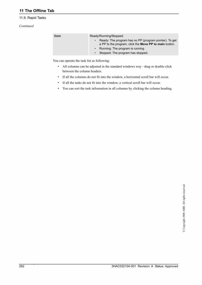
11 The Offline Tab11.9. Rapid Tasks
3HAC032104-001 Revision: A Status: Approved262
© C
opyr
ight
200
8 A
BB
. All
right
s res
erve
d.
You can operate the task list as following:
• All columns can be adjusted in the standard windows way - drag or double-click between the column headers.
• If all the columns do not fit into the window, a horizontal scroll bar will occur.
• If all the tasks do not fit into the window, a vertical scroll bar will occur.
• You can sort the task information in all columns by clicking the column heading.
State Ready/Running/Stopped:• Ready: The program has no PP (program pointer). To get
a PP to the program, click the Move PP to main button.• Running: The program is running.• Stopped: The program has stopped.
Continued

11 The Offline Tab11.10. Restart
2633HAC032104-001 Revision: A Status: Approved
© C
opyr
ight
200
8 A
BB
. All
right
s res
erve
d.
11.10. Restart
Restarting a VC1. In the Layout browser, select the controller to restart.
2. Click Restart and then click either Warmstart to activate the changes and restart the VC or I-start to restart the VC with the current system and default settings.

11 The Offline Tab11.11. Shutdown
3HAC032104-001 Revision: A Status: Approved264
© C
opyr
ight
200
8 A
BB
. All
right
s res
erve
d.
11.11. Shutdown
Shutting down a VC1. In the Offline browser, select the controller to shut down.
2. Click Shutdown and then click either Shutdown to close the connection to the VC or Terminate Virtual Controllers to end all VC processes.

11 The Offline Tab11.12. New Module
2653HAC032104-001 Revision: A Status: Approved
© C
opyr
ight
200
8 A
BB
. All
right
s res
erve
d.
11.12. New Module
Creating a module1. Click New Module to bring up a dialog box.
2. Select the module type and permission and click Create.
11 The Offline Tab11.13. Load Module
3HAC032104-001 Revision: A Status: Approved266
© C
opyr
ight
200
8 A
BB
. All
right
s res
erve
d.
11.13. Load Module
Loading a module1. Click Load Module to bring up a dialog.
2. Browse to the location of the module to be loaded to your station and click Open.

11 The Offline Tab11.14. Load Program
2673HAC032104-001 Revision: A Status: Approved
© C
opyr
ight
200
8 A
BB
. All
right
s res
erve
d.
11.14. Load Program
Loading a program1. Click Load Program to bring up a dialog box.
2. Browse to the location of the program to be loaded to your station and click Open.

11 The Offline Tab11.15. Add signals
3HAC032104-001 Revision: A Status: Approved268
© C
opyr
ight
200
8 A
BB
. All
right
s res
erve
d.
11.15. Add signals
Parts
NOTE!You must have write access to the controller to be able to open the add signal window.
Signal Name Expression Defines the name for one or more signals.
Signal Type Defines the type of signal.
Assigned Unit Defines the I/O unit to which the signal belongs.
Identification Label Optionally, offers filtering and sorting based on this category.
Unit Mapping Expression Defines the bits in the I/O memory map of the assigned unit to which the signal is mapped.
Signal Category Optionally, offer filtering and sorting based on this category.
Invent Physical Value Applies an inversion between the physical value of the signal and its logical representation in the system.

11 The Offline Tab11.16. Set Task Frames
2693HAC032104-001 Revision: A Status: Approved
© C
opyr
ight
200
8 A
BB
. All
right
s res
erve
d.
11.16. Set Task Frames
?Label overview block?>?The overview block is optional, but recommended. This is the first para of the overview block.?

11 The Offline Tab11.17. System Configuration
3HAC032104-001 Revision: A Status: Approved270
© C
opyr
ight
200
8 A
BB
. All
right
s res
erve
d.
11.17. System Configuration
OverviewThe system configuration window contains functions for making and viewing advanced system configurations, such as changing controller and baseframe positions, calibrating and setting up external axes.
The left side of the system configuration window contains a hierarchical tree with which you browse to different aspects of the system. The right side contains a property sheet for the aspect selected in the tree. Below are short descriptions of the property sheets for each aspect node of the system configuration.
CAUTION!Changing the system configurations may result in corrupted systems or unexpected robot behaviors. Be sure to understand the effects of the changes before proceeding.
The System nodeThe system node contains a box with information about the system and a button for loading new parameters (configuration files) to the system.
The task nodeThe task node has no property page.
The mechanism folder nodeThe property page of this node contains controls for mapping and setting axis and joints. It is from this page you set up external axes.
The mechanism library nodeThe property page of this node contains controls for changing the baseframe of the robot or mechanism. Here, too, you specify whether the baseframe is moved by another mechanism (coordinated motion), like a track external axis.
Updating the baseframe position1. Move the mechanical unit (robot or external axis) to its new location using the ordinary
tools for moving and placing objects.
2. In the Offline browser, select the controller for the mechanical unit.
3. Click System configuration to bring up a dialog box.
4. Select the node for the mechanical unit in the hierarchical tree. The baseframe property sheet for the robot is now displayed.
Continues on next page

11 The Offline Tab11.17. System Configuration
2713HAC032104-001 Revision: A Status: Approved
© C
opyr
ight
200
8 A
BB
. All
right
s res
erve
d.
5. Select the baseframe position values to use after restarting the robot.
6. Click OK.
Select To
Controller values Reset all changes to the baseframe made since the last time the system was started.
Stored station values Reset all changes made to the baseframe since the last time the station was saved.Optionally, you can enter new values in the baseframe coordinate boxes (relative to the controller world coordinate system).
Use current station values
Read and use the current location of the baseframe.Optionally, you can enter new values in the baseframe coordinate boxes (relative to the controller world coordinate system).
Continued
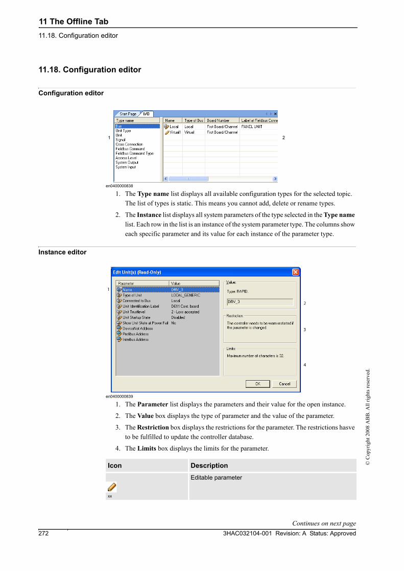
11 The Offline Tab11.18. Configuration editor
3HAC032104-001 Revision: A Status: Approved272
© C
opyr
ight
200
8 A
BB
. All
right
s res
erve
d.
11.18. Configuration editor
Configuration editor
en0400000838
1. The Type name list displays all available configuration types for the selected topic. The list of types is static. This means you cannot add, delete or rename types.
2. The Instance list displays all system parameters of the type selected in the Type name list. Each row in the list is an instance of the system parameter type. The columns show each specific parameter and its value for each instance of the parameter type.
Instance editor
en0400000839
1. The Parameter list displays the parameters and their value for the open instance.
2. The Value box displays the type of parameter and the value of the parameter.
3. The Restriction box displays the restrictions for the parameter. The restrictions hasve to be fulfilled to update the controller database.
4. The Limits box displays the limits for the parameter.
Icon Description
xx
Editable parameter
Continues on next page
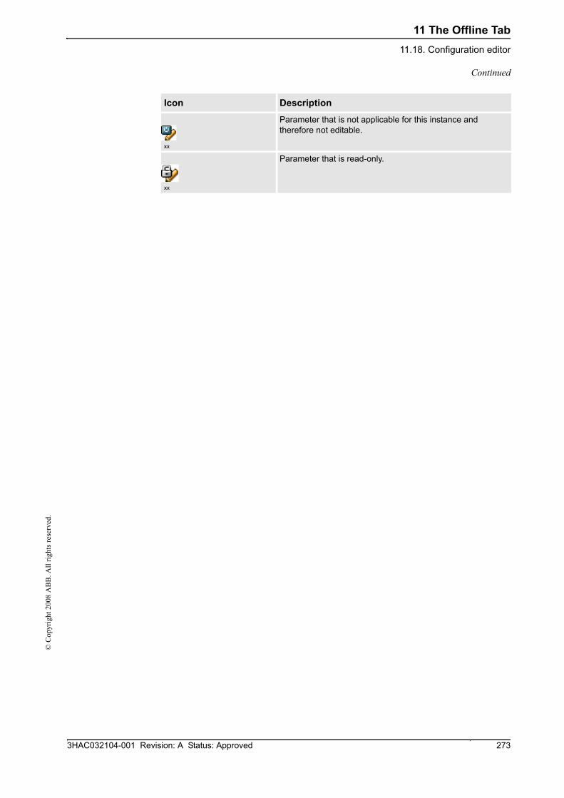
11 The Offline Tab11.18. Configuration editor
2733HAC032104-001 Revision: A Status: Approved
© C
opyr
ight
200
8 A
BB
. All
right
s res
erve
d.
xx
Parameter that is not applicable for this instance and therefore not editable.
xx
Parameter that is read-only.
Icon Description
Continued

11 The Offline Tab11.19. Load Parameters
3HAC032104-001 Revision: A Status: Approved274
© C
opyr
ight
200
8 A
BB
. All
right
s res
erve
d.
11.19. Load Parameters
PrerequisiteYou must have write access to the controller.
Loading parameters1. In the Offline/Online browser, select the configuration node.
2. Click Load Parameters to bring up a dialog box.
3. In the dialog box, select how you want to combine the parameters in the configuration file to load with the existing parameters:
4. Click Open and browse to the configuration file to load. Then click Open again.
5. In the information box, click OK to confirm that you want to load the parameters from the configuration file.
6. When the loading of the configuration file is finished, close the Select mode dialog box.
If a restart of the controller is necessary for the new parameters to take affect, you will be notified of this.
If you want to... then select...replace the entire configuration of the topic with the one in the configuration file.
Delete existing parameters before loading
add new parameters from the configuration file to the topic, without modifying the existing ones.
Load parameters if no duplicates
add new parameters from the configuration file to the topic and update the existing ones with values from the configuration file. Parameters that only exist in the controller and not in the configuration file will not be changed at all.
Load parameters and replace duplicates

11 The Offline Tab11.20. Save System Parameters
2753HAC032104-001 Revision: A Status: Approved
© C
opyr
ight
200
8 A
BB
. All
right
s res
erve
d.
11.20. Save System Parameters
Overview The system parameters of a configuration topic can be saved to a configuration file, stored on the PC or any of its network drives.
The configuration files can then be loaded into a controller. They are thereby useful as backups, or for transferring configurations from one controller to another.
File-naming conventionsThe configuration files should be named with a name that relates to their corresponding topics. When saving configuration files, the correct name for each file will be suggested by default.
Saving one configuration file1. In the Offline/Online browser, expand the Configuration node and select the topic to
save to a file.
2. Click Save System Parameters.
3. In the Save As dialog box, browse for the folder to save the file in.
4. Click Save.
Saving several configuration files1. In the Robot View Explorer, select the Configuration node.
2. Click Save System Parameters.
3. In the Save System Parameters dialog box, select the topics to save to files. Then click Save.
4. In the Browse for Folder dialog box, browse for the folder to save the files in.
Then click OK.
The selected topics will now be saved as configuration files with default names in the specified folder.

11 The Offline Tab11.20. Save System Parameters
3HAC032104-001 Revision: A Status: Approved276
© C
opyr
ight
200
8 A
BB
. All
right
s res
erve
d.

12 The Online Tab12.1. Overview
2773HAC032104-001 Revision: A Status: Approved
© C
opyr
ight
200
8 A
BB
. All
right
s res
erve
d.
12 The Online Tab12.1. Overview
The Online tabThe Online tab contains controls for managing the real controller.

12 The Online Tab12.2. Add Controller
3HAC032104-001 Revision: A Status: Approved278
© C
opyr
ight
200
8 A
BB
. All
right
s res
erve
d.
12.2. Add Controller
Adding a controller1. Click Add Controller to bring up a dialog box in which all available controllers are listed.
2. If the controller is not found in the list, type its IP address in the IP Address box, and then click Refresh.
3. Select the controller in the list and click OK.

12 The Online Tab12.3. Request Write Access
2793HAC032104-001 Revision: A Status: Approved
© C
opyr
ight
200
8 A
BB
. All
right
s res
erve
d.
12.3. Request Write Access
Overview You can access the controllers in your Robot View with either read only access or Write access. You need Write access for editing programs and configurations or in any other way change data on the controller.
Prerequisites for Write accessYou can get Write access to any controller as long as the prerequisites are fulfilled.
If the prerequisites are not fulfilled you will be denied, or lose, the Write access. This means that if you have Write access in auto mode and the controller is switched over to manual mode you will lose the Write access without any warning. This is because the FlexPendant unit by default has the Write access in manual mode, for safety reasons. The same will happen if the remote Write access in manual mode is recalled from the FlexPendant unit.
Result The Controller Status window will be updated when the request for Write access is granted.
If the Write access is denied, a message is displayed.
When the Controller is in Mode:
This has to be fulfilled:
Auto The Write access must not be taken by any other user.
Manual The remote Write access must be granted on the FlexPendant. For safety reasons, a FlexPendant user can also recall this remote Write access in manual mode.

12 The Online Tab12.4. Release Write Access
3HAC032104-001 Revision: A Status: Approved280
© C
opyr
ight
200
8 A
BB
. All
right
s res
erve
d.
12.4. Release Write Access
Overview You can access the controllers in your Robot View with either read only access or write access. Since several users can be logged on to one controller but only one can have write access, you can release the write access when you do not need it anymore.
Result The Controller Status window will be updated when your access right has changed from read/write to read only.

12 The Online Tab12.5. Import Options
2813HAC032104-001 Revision: A Status: Approved
© C
opyr
ight
200
8 A
BB
. All
right
s res
erve
d.
12.5. Import Options
Importing system options1. Click Import System Options to bring up a dialog box.
2. In the Option source box, enter the path to the folder where the options to import are located. You can also click the Browse button and browse to the folder.
3. In the Media pool destination box, enter the path to the media pool you want to store the options in. You can also click the Browse button and browse to the media pool folder.
4. Select the options to import and click Import.
To select several options at once, do one of the following:
5. Click OK.
Removing system options1. Click Import System Options to bring up a dialog box.
2. In the Media pool destination list, enter the path to the media pool from which you want to delete the options. You can also click the Browse button and browse to the media pool folder.
3. Select the options to delete and click Remove.
To select several options at once, do one of the following:
4. Click OK.
To select then hold down several adjacent options the SHIFT key and select the first and the last option.
several non-adjacent options the CTRL key and select each option.
To select then hold down several adjacent options the SHIFT key and select the first and the last option.
several non-adjacent options the CTRL key and select each option.

12 The Online Tab12.6. User Accounts
3HAC032104-001 Revision: A Status: Approved282
© C
opyr
ight
200
8 A
BB
. All
right
s res
erve
d.
12.6. User Accounts
OverviewAll the procedures below require the following steps to be taken before managing the details:
1. In the Online browser, select the controller to which you want to manage a user. or group
2. From the Online tab, request write access to the controller.
3. On the Online tab, click User Accounts.
Users tabWith the Users tab you set which users will be able to log on to the controller and which groups the users shall belong to.
en0400001104
Users tab Parts1. The Add button. Opens a dialog box for adding new users.
2. The Edit button. Opens a dialog box for changing the user’s log on name and password.
3. The Delete button. Deletes the selected user account from the controller.
4. The Users on this Controller list. Shows the user accounts defined on this controller. The list has two columns:
Column Description
User The name of the user account
Status Shows if the account is activated or deactivated. When deactivated, it is not possible to log on using that account.
Continues on next page

12 The Online Tab12.6. User Accounts
2833HAC032104-001 Revision: A Status: Approved
© C
opyr
ight
200
8 A
BB
. All
right
s res
erve
d.
5. The Activated/Deactivated item box. Changes the status of the user account.
6. The User’s groups/User’s grants list.
The User’s groups list shows which group(s) the user is a member of. For changing the membership of a group, select or clear the checkbox in front of the group name.
The User’s grants list shows the available grants for the selected User’s group(s). When selecting a grant from the User’s grants list, a description of the selected grant appears.
en0500001572
Adding a user1. On the Users tab, click Add to bring up a dialog box.
2. In the User Name box, enter the user name. Use only characters from the ISO Latin -1 character set and no more than 16 characters.
3. In the Password box, enter the user's password. The password you type in will not be visible. Use only characters from the ISO Latin -1 character set and no more than 16 characters.
4. In the Retype Password box, enter the user's password again.
5. Click OK to add the new user and close the dialog box.
6. Click OK.
Deleting a user1. On the Users tab, select the user to delete from the Users on this controller list and click
Delete.
2. To the question Are you sure you want to remove this user?, answer Yes.
3. Click OK.
Continued
Continues on next page

12 The Online Tab12.6. User Accounts
3HAC032104-001 Revision: A Status: Approved284
© C
opyr
ight
200
8 A
BB
. All
right
s res
erve
d.
Setting up group membership1. On the Users tab, select the user from the Users on this controller list.
2. In the User’s groups list, select the groups the user shall be a member of.
3. Click OK.
Changing a name or password1. On the Users tab, select the user to edit from the Users on this controller list and click
Edit user.
This opens the Edit dialog box.
2. To change the user name, enter the new name in the User Name box. Use only characters from the ISO Latin -1 character set and no more then 16 characters.
3. To change the password, enter the new password in the Password box, then retype the password in the Retype Password box. Use only characters from the ISO Latin -1 character set and no more then 16 characters.
4. Click OK to save the changes to the user and close the dialog box.
5. Click OK.
Activating or deactivating a user1. On the Users tab, select the user from the Users on this controller list and click the status
text (Activated or Deactivated). An item box appears and you can change the status.
The user's new state is now displayed in the status column of the Users on this controller list.
2. Click OK.
Continued
Continues on next page

12 The Online Tab12.6. User Accounts
2853HAC032104-001 Revision: A Status: Approved
© C
opyr
ight
200
8 A
BB
. All
right
s res
erve
d.
Exporting a user list1. On the Users tab, select the user from the Users for this Controller list and click Export.
This opens a Save as dialog box, in which you specify the name and location for the file with the user list.
Importing a user list1. On the Users tab, select the user from the Users for this Controller list and click Import.
This opens an Open file dialog box, in which you browse to the file with the list to import.
When you have selected the file, the ImportOptionsForm dialog appears.
Adding a group1. On the Groups tab, click Add.
This opens the Add new group dialog box.
2. In the Group Name box, enter the name of the group. Use only characters from the ISO Latin -1 character set and no more than 16 characters.
3. Click OK to add the new group and close the dialog box.
4. Click OK.
Renaming a group1. On the Groups tab, select the group to rename from the Groups on this controller list
and click Rename.
This opens the Rename Group dialog box.
2. In the Group Name box, enter the name of the group. Use only characters from the ISO Latin -1 character set and no more than 16 characters.
3. Click OK to rename the group and close the dialog box.
Select ... Description
Delete existing users and groups before importing
Earlier groups and users will be deleted.
Advanced options A new dialog appears.Import users but don’t replace duplicates means that you will not replace the existing users.Import users and replace duplicates means that you will replace the existing users.Import groups but don’t replace duplicates means that you will not replace the existing groups.Import groups and replace duplicates means that you will replace the existing groups.
Continued
Continues on next page

12 The Online Tab12.6. User Accounts
3HAC032104-001 Revision: A Status: Approved286
© C
opyr
ight
200
8 A
BB
. All
right
s res
erve
d.
4. You will now be asked if you want the users who belong to this group to continue belonging to a group with the old name as well as the new one.
5. Click OK.
Deleting a group1. On the Groups tab, select the group to delete from the Groups on this controller list and
click Delete.
2. You will now be asked if you want the users who belong to this group to continue belonging to it though it is not valid.
3. Click OK.
Giving grants to a group1. On the Groups tab, select the group from the Groups on this controller list.
2. In the Controller grants/Application grants list, select the grants to give to the group.
3. Click OK.
Click To
Yes Let the users of the group be members to groups with both the old and the new name. However, the old group will no longer be defined in the controller's UAS since it is replaced by the new group. This option might be useful if you plan to recreate the old group, or copy the user's settings to another controller who has the old group defined.
No Delete the user's memberships to the old group. This is to just replace the old group name with the new one.
Cancel To cancel the change and keep the old group name, with its user's memberships.
Click To
Yes Let the users of the group remain members to it even if it is no longer defined in the controller's UAS. This option might be useful if you plan to recreate the group, or copy the user's settings to another controller who has the group defined.
No Delete the user's memberships to the group.
Cancel Cancel the change and keep the group, with its user's memberships.
Continued

12 The Online Tab12.7. UAS Grant Viewer
2873HAC032104-001 Revision: A Status: Approved
© C
opyr
ight
200
8 A
BB
. All
right
s res
erve
d.
12.7. UAS Grant Viewer
The Grants Overview dialog box
en0400001106
PartsYou can sort the information in all three columns by clicking the column heading.
1. The Grant column shows the name of the grant key.
2. The Valid column shows from which RobotWare versions the grant is valid.
Systems with different RobotWare versions may use different grants. When you install a system on a controller, the grants for that system are added to the controller’s grant list. Grants are never removed from the grant list but may be declared invalid if they are not applicable for a system. All this is handled automatically during installation of systems.
3. The Groups owning this Grant column shows which groups on this controller that have the grant.
Examples of common actions to perform
Action Necessary grants
Rename the controller.(A restart of the controller is necessary.)
Modify controller propertiesRemote warm start
Change system parameters and load configura-tion files.
Modify configurationRemote warm start
Install a new system. Administration of installed system
Perform a backup.(A restart of the controller is necessary.)
Backup and saveRemote warm start
Continues on next page

12 The Online Tab12.7. UAS Grant Viewer
3HAC032104-001 Revision: A Status: Approved288
© C
opyr
ight
200
8 A
BB
. All
right
s res
erve
d.
Controller grants
Restore a backup.(A restart of the controller is necessary.)
Restore a backupRemote warm start
Load/delete modules. Load program
Create new modules. Load program
Edit code in RAPID modules. Edit RAPID code
Save modules and programs to disk. Backup and save
Start program execution from Task Window. Execute program
Create a new I/O signal, that is, add a new instance of the type Signal.( A restart of the controller is necessary.)
Modify configurationRemote warm start
Set the value of an I/O signal. I/O write access
Access to controller disks from File Management Window.
Read access to controller disksWrite access to controller disks
Action Necessary grants
Full access This grant includes all controller grants, also new grants added in future RobotWare versions. The grant does not include any application grants.
Manage UAS settings Gives access to read and write the UAS configuration, that is to read, add, remove and modify UAS users and groups.
Execute program Gives access to perform the following:• Start/step program (stop is always allowed)• Move PP to Main• Execute service routines
Perform ModPos and HotEdit Gives access to perform the following:• Modify or teach positions in RAPID code (ModPos)• During execution modify positions in RAPID code as
single points or as a path (HotEdit)• Restore ModPos/HotEdit positions to original• Modify current value of any RAPID variable
Modify current value Gives access to modify current value of any RAPID variable. This grant is a subset of the grant Perform ModPos and HotEdit. (Available from RobotWare 5.07.03.)
I/O write access Gives access to perform the following:• Set I/O signal value• Set signal as simulated and remove simulation• Set I/O unit and bus as enabled/disabled
Backup and save Gives access to perform a backup and to save modules, programs and configuration files.
Restore a backup Gives access to restore backup and perform B-start.
Modify configuration Gives access to modify the configuration database, that is to load configuration files, change system parameter values and add/delete instances.
Load program Gives access to load/delete modules and programs.
Remote warm start Gives access to perform warm start and shutdown (S-start) from a remote location. No grant is required to perform warm start via a local device, as for example the FlexPendant.
Continued
Continues on next page

12 The Online Tab12.7. UAS Grant Viewer
2893HAC032104-001 Revision: A Status: Approved
© C
opyr
ight
200
8 A
BB
. All
right
s res
erve
d.
Edit RAPID code Gives access to perform the following:• Modify code in existing RAPID modules• Frame calibration (tool, workobj)• Commit ModPos/HotEdit positions to current values• Rename program
Program debug Gives access to perform the following:• Move PP to routine• Move PP to cursor• HoldToRun• Activate/deactivate RAPID tasks• Request write access from the FlexPendant• Acknowledge Auto mode without restoring simulated
I/O signals or deactivated tasks• Enable/disable non-motion execution
Decrease production speed Gives acces to decrease speed from 100% in Auto mode.This grant is not required if speed is already below 100%, or controller is in Manual mode.
Calibration Gives access to perform the following:• Fine calibrate mechanical unit• Calibrate base frame• Update/clear SMB data
Note! Frame calibration (tool, wobj) requires the grant Edit RAPID code. Manual offset of mechanical unit calibration data and loading new calibration data from file require the grant Modify configuration.
Administration of installed systems
Gives access to perform the following:• Install new system• P-start• I-start• X-start• C-start• Select System• Install system from device
This grant gives full FTP access, that is, the grant gives the same rights as Read access to controller disks and Write access to controller disks.
Read access to controller disks
Gives external read access to controller disks. This grant is only valid for explicit disk access, for example with an FTP client or the File Manager of RoboStudioOnline.It is possible, for example, to load a program from /hd0a without this grant.
Write access to controller disks
Gives external write access to controller disks. This grant is only valid for explicit disk access, for example with an FTP client or the File Manager of RoboStudioOnline.It is possible, for example, to save a program to the controller disk or perform a backup without this grant.
Modify controller properties Gives access to set controller name, controller ID and system clock.
Delete log Gives access to delete messages in the controller Event Log.
Revolution counter update Gives access to update the revolution counter.
Continued
Continues on next page

12 The Online Tab12.7. UAS Grant Viewer
3HAC032104-001 Revision: A Status: Approved290
© C
opyr
ight
200
8 A
BB
. All
right
s res
erve
d.
Application grants
Access to the ABB menu on FlexPendant
Value true gives access to the ABB menu on the Flex-Pendant. This is the default value if a user does not have the grant.Value false means that the user cannot access the ABB menu when the controller is in Auto mode.The grant has no effect in Manual mode.
Log off FlexPendant user when switching to Auto mode
A user having this grant is automatically logged off from the FlexPendant when switching from Manual mode to Auto mode.
Continued

12 The Online Tab12.8. FlexPendant Viewer
2913HAC032104-001 Revision: A Status: Approved
© C
opyr
ight
200
8 A
BB
. All
right
s res
erve
d.
12.8. FlexPendant Viewer
OverviewFlexPendant Viewer is an add-in to RobotStudio that retrieves and displays a screenshot from the FlexPendant. The screenshot is generated automatically at the moment of the request.
PrerequisitesTo install FlexPendant Viewer, the system must have the option PC interface installed.
The controller you want to retrieve screen shots from must be added to your robot view.
A FlexPendant must be connected to the controller. If no FlexPendant is currently connected (option Hot plug is installed and the jumper plug is used) then no screen shot can be retrieved.
Using FlexPendant Viewer1. Make sure you are connected to the controller.
2. Click FlexPendant Viewer.
A screen shot will be displayed in the workspace.
3. To reload the screen shot, click Reload in the workspace.
4. To set an automatic reload period for the screen shot, click on the menu Tools, point to FlexPendant Viewer and click Configure.
Set the desired reload period and select the check-box Activated. Then click OK.
Results on the controllerThe screenshot will automatically be saved as a file on the controller. When a new request is sent, a new screenshot is generated and saved, overwriting the previous file.
No message will be displayed on the FlexPendant.

12 The Online Tab12.9. Device Browser
3HAC032104-001 Revision: A Status: Approved292
© C
opyr
ight
200
8 A
BB
. All
right
s res
erve
d.
12.9. Device Browser
Updating the tree view1. To update the tree view, press F5.
Displaying the properties of a device1. Select a device in the tree view to view its properties or values in the right-hand pane.
Displaying a trend1. Select a device in the tree view and then double-click any property in the right-hand pane
that has a numerical value to bring up a trend view.
The trend view collects data at a rate of one sample per second.
Hiding, stopping, starting or clearing a trend1. Right-click anywhere in the trend view and then click the appropriate command.

13 The Add-Ins Tab13.1. Overview
2933HAC032104-001 Revision: A Status: Approved
© C
opyr
ight
200
8 A
BB
. All
right
s res
erve
d.
13 The Add-Ins Tab13.1. Overview
The Add-Ins tabThe Add-Ins tab contains the control for PowerPacs and the VSTA.

13 The Add-Ins Tab13.2. Visual Studio Tools for Applications
3HAC032104-001 Revision: A Status: Approved294
© C
opyr
ight
200
8 A
BB
. All
right
s res
erve
d.
13.2. Visual Studio Tools for Applications
Building an add-in1. Click Visual Studio Tools for Applications.
2. Create a new project or open an existing one. Compose or edit as required.
3. To build the add-in, from the Build menu, click Build.
The add-in will be loaded in RobotStudio and appear as a user add-in in the Add-In browser.
4. Save the project to your hard disk if you want the add-in to remain with the user. Otherwise, open a station, right-click in the Add-In browser and then click Add to Station.

14 The Context Menus13.2. Visual Studio Tools for Applications
2953HAC032104-001 Revision: A Status: Approved
© C
opyr
ight
200
8 A
BB
. All
right
s res
erve
d.
14 The Context Menus

14 The Context Menus14.1. Add to Path
3HAC032104-001 Revision: A Status: Approved296
© C
opyr
ight
200
8 A
BB
. All
right
s res
erve
d.
14.1. Add to Path
Creating a move instruction based on an existing target1. Select the target for which to create the move instruction.
2. From the Home menu, in the Path Programming group, select the type of move instruction to create.
3. Click Add to Path.
The move instruction will appear under the path node as a reference to the original target.

14 The Context Menus14.2. Align Frame Orientation
2973HAC032104-001 Revision: A Status: Approved
© C
opyr
ight
200
8 A
BB
. All
right
s res
erve
d.
14.2. Align Frame Orientation
The Align Frame Orientation dialog box
Reference Specify the frame or target for which you want to align the selected objects here.
Align Axis The axis you specify here will be aligned as on the reference target/frame for all selected objects.
Lock Axis The axis you specify here will not be changed on the selected objects by the align function, but will keep its orientation.

14 The Context Menus14.3. Align Target Orientation
3HAC032104-001 Revision: A Status: Approved298
© C
opyr
ight
200
8 A
BB
. All
right
s res
erve
d.
14.3. Align Target Orientation
Aligning target orientation1. Select the targets whose orientation you wish to change.
2. Click Align Target Orientation to bring up a dialog box.
3. In the Reference box, specify the target whose orientation you want to use as reference, by first click in the box and then selecting the target either from the graphics view or the Layout browser.
4. In the Align Axis box, select the axis whose orientation you want to copy from the reference target to the selected ones.
5. In the Lock Axis box, select the axis to rotate the target around. The orientation of this axis will not be changed on the targets. For example, if the Z axis of all targets are orientated normally to the surface of the work piece and you want to keep it this way, you should lock the Z axis.
6. Click Apply.
TIP!You can change the Align and Lock axis and click Apply again to reorientate the targets until you deselect them.

14 The Context Menus14.4. Attach to
2993HAC032104-001 Revision: A Status: Approved
© C
opyr
ight
200
8 A
BB
. All
right
s res
erve
d.
14.4. Attach to
Attaching an object1. In the Layout browser, right-click the child object, click Attach to and click the parent
object in the list.
Attaching an object by drag and drop1. In the Layout browser, drag the child object to the parent object.
2. In the displayed message, click the corresponding button:
To Click
attach the child object and move it to the attachment point
Yes
attach the child object and keep its position Nonot perform the attachment Cancel

14 The Context Menus14.5. Auto-Configuration
3HAC032104-001 Revision: A Status: Approved300
© C
opyr
ight
200
8 A
BB
. All
right
s res
erve
d.
14.5. Auto-Configuration
Setting a robot axis configuration for all targets in a path1. In the Paths&Targets browser, select a path and then click AutoConfiguration. The
robot now steps through each target in the path and sets the configurations.
2. If the first target in the path has no configuration assigned, the one closest to the robot’s current configuration will be used. If the first target has a configuration assigned, the assigned one will be used. Thus, the result of the autoconfiguration may vary depending on the first target’s configuration.

14 The Context Menus14.6. Check Reachability
3013HAC032104-001 Revision: A Status: Approved
© C
opyr
ight
200
8 A
BB
. All
right
s res
erve
d.
14.6. Check Reachability
Checking the reachability1. In the Paths&Targets browser, select the task that contains the targets or move
instructions to check.
2. Click Reachability to open a dialog box. Make sure that the Check reachability for targets, paths, move instructions check box is selected.
Optionally, select or clear the Check reachability for targets, paths, move instructions check box for showing and hiding the reachability display.
3. In the Layout browser, select the objects whose reachability you want to check. If paths are selected, the reachability will be checked for all move instructions in each path.
4. In the Reachability dialog box, click Add.
The frames for the selected objects will now change color based on their reachability status.
Color Means
Green The object can be reached.
Yellow The object can be reached at its current position, but not at its current orientation
Red The object cannot be reached at its current position.
14 The Context Menus14.7. Configurations
3HAC032104-001 Revision: A Status: Approved302
© C
opyr
ight
200
8 A
BB
. All
right
s res
erve
d.
14.7. Configurations
Manually setting a robot axis configuration for single targets1. In the Paths&Targets browser, select a target and then click Configurations to bring up
a dialog box.
2. If more than one configuration solution exist, examine them by clicking them, one at a time.
The position of the robot with the selected configuration will be displayed in the graphics window, and the joint values for the configuration will be displayed in the joint values list below the configurations list.
In most cases, selecting a configuration similar to the previous one is the best choice.
3. Select the configuration to use and click Apply.

14 The Context Menus14.8. Control Panel
3033HAC032104-001 Revision: A Status: Approved
© C
opyr
ight
200
8 A
BB
. All
right
s res
erve
d.
14.8. Control Panel
The Control Panel dialog box
Operation Mode This group contains the three operational modes of the controller represented by option buttons.
Auto This option corresponds to the Auto mode on the FlexPendant.Moving between the Auto and Manual Full Speed options must proceed via the Manual option.
Manual This option corresponds to the Manual mode on the Flex-Pendant.
Manual Full Speed This option corresponds to the Manual 100% mode on the Flex-Pendant.Moving between the Auto and Manual Full Speed options must proceed via the Manual option.
Push Motors Click this button to turn on the motors.
Enable Device In a manual mode, click this button to simulate holding the enabling device to turn on the motors.
Release Device In a manual mode, click this button to turn off the motors.
Reset Emergency Stop If the controller enters the emergency stop state, click this button to reset the state.

14 The Context Menus14.9. Convert Frame to Workobject
3HAC032104-001 Revision: A Status: Approved304
© C
opyr
ight
200
8 A
BB
. All
right
s res
erve
d.
14.9. Convert Frame to Workobject
Converting a frame to a workobject1. In the Paths&Targets browser, select a frame.
2. Click Convert Frame to Workobject. The new workobject will appear in the browser.
3. Optionally, rename or edit the workobject in any way.

14 The Context Menus14.10. Convert to Move Circular
3053HAC032104-001 Revision: A Status: Approved
© C
opyr
ight
200
8 A
BB
. All
right
s res
erve
d.
14.10. Convert to Move Circular
PrerequisitesAt least two targets, the via-point target and the end point target, must have been created.
A path containing at least the via-point target and the end point target, in correct order, must have been created.
Converting to Move Circular1. In the Paths&Targets browser, expand the path node that contains the move instruction
to be converted.
2. Select the move instruction that contains the via-point of the circular motion together with the succeeding move instruction, which will serve as the end point. You can select several instructions by holding down the SHIFT key while clicking the instructions.
3. Click Convert to Move Circular. The two selected move instructions will be converted to a circular move instruction, which includes the via-point and the end point.
TIP!To convert two move instructions to a circular motion, you can also select and right-click both move instructions at once and then click Convert to Circular.

14 The Context Menus14.11. Copy / Apply Orientation
3HAC032104-001 Revision: A Status: Approved306
© C
opyr
ight
200
8 A
BB
. All
right
s res
erve
d.
14.11. Copy / Apply Orientation
Copying and applying an orientation1. In the browser, select the object or target from which to copy the orientation.
2. On the Modify menu, click Copy Orientation.
3. In the browser, select the object or target to which to apply the orientation.
4. On the Modify menu, click Apply Orientation. This can be performed on several targets or a group of selected targets.

14 The Context Menus14.12. Detach
3073HAC032104-001 Revision: A Status: Approved
© C
opyr
ight
200
8 A
BB
. All
right
s res
erve
d.
14.12. Detach
Detaching an object1. In the Layout browser, right-click the attached object (child) and then click Detach. The
child will be detached from the parent and return to its position before the attachment.

14 The Context Menus14.13. Execute Move Instruction
3HAC032104-001 Revision: A Status: Approved308
© C
opyr
ight
200
8 A
BB
. All
right
s res
erve
d.
14.13. Execute Move Instruction
PrerequisitesThe move instruction must exist.
A virtual controller must be running for the robot with the move instruction.
Executing a move instruction1. In the Paths&Targets browser, browse to the motion instruction to execute through the
Controller, Tasks and Paths nodes.
2. Click Execute move instruction. The TCP of the active robot will move from the current location to the motion instruction according to the programed motion properties. If the target for the motion instruction does not have a stored configuration, the robot will use the configuration nearest the current one.

14 The Context Menus14.14. Graphic Appearance
3093HAC032104-001 Revision: A Status: Approved
© C
opyr
ight
200
8 A
BB
. All
right
s res
erve
d.
14.14. Graphic Appearance
OverviewWith the graphic appearance dialog box you set the graphic properties for an individual object. The settings made here override the generic settings made in the options dialog box. The dialog box contains one view group where you select the part of the object to affect, and three tabs with settings.
Graphic Appearance: The View group
Graphic Appearance: The Rendering tab
Graphic Appearance: The Material tab
Graphic Appearance: The Texture tab
Selection Select the parts of the object whose appearance you wish to change. When Body or Surface/Curve is selected, you select the object to work with in the preview display.
Backface culling Select this check box to view only the front sides (the direction of the positive normal) of the faces in the model. This improves the graphics performance and indicates the directions of the faces in the model.Clear this check box to also display the back sides of the faces in the model. This ensures that the model is displayed correctly even if the faces are in the wrong direction. If a model with faces in the wrong direction is used for programing, you might get unpredicted results.
Twosided lightning Select this check box to light the object from two sides.Clear this check box to light the object from one side.
Flat shade Select this check box to change the appearance of shades.
Flip normals Click this button to change the direction of all faces on the model.
Line width Specify the width of lines in the object here.
The detail level options Select the detail level of the model here. Only the levels selected in the Options dialog box when the object was created or imported are available.
Simple Color Click this color box to select another color for the object.
Transparency Use this slider to control the transparency of the object.
The color boxes Set the color of the object for different light situations here.
Shininess Specify the reflectiveness of the object here.
Base texture Select an image or a video file to apply on the surface here. To add files to the list, click the browse button next to the list and browse to the files to add.If the applied texture is not visible, it might be due to the large differences in the ratio between the dimensions of the object and the texture. Use Normalize described below to set the ratio to 1.
Continues on next page

14 The Context Menus14.14. Graphic Appearance
3HAC032104-001 Revision: A Status: Approved310
© C
opyr
ight
200
8 A
BB
. All
right
s res
erve
d.
Blend with material Select this check box to blend the texture with the colors and properties specified on the Material tab.
Swap u/v Click this button to swap the horizontal and vertical directions of the texture.
Modify Select along which directions the commands listed below shall be applied.u is the horizontal axis of the texture.v is the vertical axis of the texture.
Normalize Click this button to set the ratio between the dimensions of the object and the texture to 1.
Flip Click this button to invert the coordinates along the selected axes. This is the same as mirroring around the other axis.
Stretch Click this button to stretch the texture along the selected axes.
Shrink Click this button to shrink the texture along the selected axes.
Shift < Click this button to move the texture along the selected axes.
Shift> Click this button to move the texture along the selected axes.
Continued

14 The Context Menus14.15. Interpolate Path
3113HAC032104-001 Revision: A Status: Approved
© C
opyr
ight
200
8 A
BB
. All
right
s res
erve
d.
14.15. Interpolate Path
Reorienting targets in a path by interpolation1. In the Layout browser or the graphics window, select the path with the targets to reorient.
2. Click Interpolate Path. to bring up a dialog box.
3. With the Interpolate type options, select whether to use Linear or Absolute interpolation.
Linear interpolation distributes the difference in orientation evenly, based on the targets positions along the length of the path. By contrast, absolute interpolation distributes the difference in orientation evenly, based on the targets’ sequence in the path.
4. If using the Select Start/End option, select the start and end targets for the interpolation in the Start target and End target boxes, respectively.
5. Optionally, with the Lock Axis options, select an axis to lock.
6. Click Apply.

14 The Context Menus14.16. Invert
3HAC032104-001 Revision: A Status: Approved312
© C
opyr
ight
200
8 A
BB
. All
right
s res
erve
d.
14.16. Invert
Inverting the direction of a face1. Right-click in the Modeling browser, point to Filter and make sure that both Show
Bodies and Show Faces are selected.
2. In the Modeling browser, expand the node for the object and browse down to and select the face which direction you want to invert.
3. In the Modeling browser, expand the node for the object and browse down to and select the face whose direction you want to invert.
4. Click Invert. If the option backface culling is activated, the face will now shift from visible to not visible, or the other way around, depending on from which direction you view the face. If backface culling is deactivated, there will be no visible indication that the direction of the face has been inverted.

14 The Context Menus14.17. Jump to Target
3133HAC032104-001 Revision: A Status: Approved
© C
opyr
ight
200
8 A
BB
. All
right
s res
erve
d.
14.17. Jump to Target
Jumping to a target1. In the Paths&Targets browser, browse to the target to jump to through the Controller,
Tasks and WorkObjects nodes.
2. Click Jump to target.
If the target has a valid configuration for the robot axes stored, the active TCP of the robot will immediately be positioned at the target. If no valid configuration is stored, the Select Robot configuration dialog box is displayed.
3. In the Select Robot Configuration dialog box, select a suitable configuration solution and click Apply. The selected configuration is now stored with the target.
NOTE!You can deactivate the configuration check when jumping to targets. The robot will then use the configuration solution closest to the current one when reaching the target. For more information, see RobotStudio Options on page 160.

14 The Context Menus14.18. The Library Group
3HAC032104-001 Revision: A Status: Approved314
© C
opyr
ight
200
8 A
BB
. All
right
s res
erve
d.
14.18. The Library Group
Modifying a library component1. In the Layout browser, select the library you wish to modify.
2. Click Disconnect Library.
3. Select the library and then make any modifications to it.
4. Select the modified library, and then click Save As Library.

14 The Context Menus14.19. Mechanism Joint Jog
3153HAC032104-001 Revision: A Status: Approved
© C
opyr
ight
200
8 A
BB
. All
right
s res
erve
d.
14.19. Mechanism Joint Jog
Jogging the joints of a robot1. In the Layout browser, select the robot.
2. Click Mechanism Joint Jog to bring up a dialog box.
3. Each row in the Jog Joints dialog box represents a joint of the robot. Jog the joints either by clicking and dragging the bar at each row, or by using the arrows to the right of each row.
Set the length of each step in the Step box.
The Mechanism Joint Jog dialog box
Joint Move the joints of the objects by dragging the slider on the row corresponding to each joint. Alternatively, click the buttons to the right of the row, or type a value.
Cfg The current configuration value.
TCP The current position of the TCP.
Step Specify the length of the joint movements for each click of the buttons to the right of each joint row.
External Axis If the robot uses external axes, you can select an axis to jog from this list. The external axes must belong to the same task as the object you are jogging for occurring in this list. If no external axes are present in the same task, this list is not available.
Lock TCP Select this check box to reposition the robot according to the jogging of the external axis.For track-external axes the robot will reposition so that the TCP is locked relative to the world coordinate system.For positioner-external axes the robot will reposition so that the position of the robot’s TCP is locked relative to the attachment point of the positioner. The robot will move with the positioner the same way as when using multi-robot jog.If no external axes are present in the same task, this check box is not available.
External axes joint Move the joint of the external axes by dragging the slider on the row corresponding to each joint. Alternatively, click the buttons to the right of the row, or type a value.If no external axes are present in the same task, this check box is not available.

14 The Context Menus14.20. Mechanism Linear Jog
3HAC032104-001 Revision: A Status: Approved316
© C
opyr
ight
200
8 A
BB
. All
right
s res
erve
d.
14.20. Mechanism Linear Jog
Jogging the TCP of a robot by using the Linear Jog dialog box1. In the Layout browser, select the robot.
2. Click Mechanism Linear Jog to bring up a dialog box.
3. Each row in the Linear Jog dialog box represents a direction or rotation for the TCP. Jog the TCP along the preferred direction or rotation, either by clicking and dragging the bar at each row, or by using the arrows to the right of each row.
4. From the Reference list, you can select the coordinate system that you want to jog the robot relative to.
5. In the Step box, specify the step movement per deg/rad.
14 The Context Menus14.21. Mirror Path
3173HAC032104-001 Revision: A Status: Approved
© C
opyr
ight
200
8 A
BB
. All
right
s res
erve
d.
14.21. Mirror Path
The Mirror Path dialog box
Duplicate Select this option to keep the existing path when mirroring.
Replace Select this option to remove the existing path after mirroring.
X-Y, X-Z and Y-Z Select the plane to mirror the path around with these options. The plane is defined by the selected axes and position of the reference coordinate system selected below.
Reference Select the frame or coordinate system to define the mirror plane in.To use another frame than any of the predefined ones, select Select Frame from the list and specify the frame in the box below.
Select Frame If Select Frame is used as Reference frame, specify the frame to use here by first clicking in the box and then selecting the frame from the graphics window or the Layout browser.
Flip axis X/YZ Select one of these options to mirror the orientation of the targets. When any of these are selected, the robot will approach the targets in a mirrored way.The axis you select will change the most for achieving the mirrored orientation, while the other one will be kept as near to its current direction as possible. The axis that is set to the robot’s approach vector cannot be selected.
Keep orientation Select this option to keep the orientation of the targets. When selected, the robot will go to the mirrored position, but approach the target from the same direction as for the original target.
Mirror Robot Configura-tion
Select this option to also mirror the robot axis configuration for the targets. Selecting this option will mirror the robot’s motions completely.For using this option, the following conditions must be met:
• The Reference frame must be set to Baseframe.• The Mirror plane must be set to X-Z.• The tool of each move instruction must have its TCP in
the X-Z plane of tool0.• All targets in the path must have robot axis configuration
set.• The virtual controller must be running.
More / Less Click this button to show or hide the commands for naming and location of generated targets and paths.
New path name Specify the name of the path that will be generated by the mirroring here.
Target prefix Specify a prefix for the targets that will be generated by the mirroring here.
Receiving robot Specify the robot task in which the new targets and path shall be created.
Receiving work object Specify the work object in which the new targets shall be created.

14 The Context Menus14.22. Modify Curve
3HAC032104-001 Revision: A Status: Approved318
© C
opyr
ight
200
8 A
BB
. All
right
s res
erve
d.
14.22. Modify Curve
Extending a curve with a straight line in the direction of the curve’s tangent1. Click Modify curve to bring up a dialog box.
2. Select Extend as modify method and then click the curve segment, close to the appropriate vertex.
Note that when you rest the pointer over the curve the endpoint closest to the pointer is highlighted. This is the endpoint that will be selected for extension when you click the curve.
3. In the Distance from endpoint box, enter the length of the extension. In the graphics window a yellow line displays a preview of the extension.
4. Click Apply.
Joining curves1. Click Modify curve to bring up a dialog box.
2. Select Join as modify method and then click the curves to join in the graphics window. The curves may be either intersecting or adjacent to be joined.
The Selected curves list displays the curves that will be joined. To remove a curve from the list, select the list entry and press the DEL key.
3. In the Tolerance list, enter a value in millimeters. Adjancent curves whose end points lie within the tolerance will be valid for the operation.
4. Click Apply.
Projecting curves on a surface1. Click Modify curve to bring up a dialog box.
2. Select Project as modify method and then click the curves to project in the graphics window.
Note that when you rest the pointer over the curve, the projection direction is displayed. The project direction is always the negative Z direction of the User Coordinate System. To change the projection direction, create a new frame with the desired orientation and set it as user coordinate system.
The Selected curves list displays the curves that will be projected. To remove a curve from the list, select the list entry and press the DEL key.
3. Click in the Target bodies list and then click the bodies to project on in the graphics window. The bodies must be in the projection direction and be big enough to cover the projected curves.
To remove a bodies from the list, select the list entry and press the DEL key.
4. Click Apply. A new curve will now be created in a new part, wrapped around the surface of the selected bodies.
Continues on next page

14 The Context Menus14.22. Modify Curve
3193HAC032104-001 Revision: A Status: Approved
© C
opyr
ight
200
8 A
BB
. All
right
s res
erve
d.
Reversing curves1. Click Modify curve to bring up a dialog box.
2. Select Reverse as modify method and then click the curves to reverse in the graphics window.
Note that when resting the pointer over a curve, the current direction of the curve is displayed by yellow arrows.
The Selected curves list displays the curves that will be reversed. To remove a curve from the list, select the list entry and press the DEL key.
3. Click Apply. The curves will now be reversed.
Splitting a curve1. Click Modify curve to bring up a dialog box.
2. Select Split as modify method and then click the curve at the point to split at. Only open curves can be split.
Note that when you rest the pointer over the curve, point of the split is highlighted. This point is affected by the current snap mode setting.
3. Click Apply. The curve will now be split to two separate curves in the same part.
Trimming a curve1. Click Modify curve to bring up a dialog box.
2. Select Trim as modify method and then click the curve segment to trim.
Note that when you rest the pointer over the curve, the closest vertices are highlighted. The segment between these points will be trimmed.
3. Click Apply. The selected part of the curve will now be removed.
Generic content of the Modify Curve dialog box
Extend Extend a curve at any vertex with a straight line in the direction of the curve’s tangent.
Join Join two or more curves into one. The original curves will be deleted when joining curves.
Project Project a curve onto a surface or a body, creating a new curve on the target part.
Reverse Reverse the direction of curves.
Split Split a curve in two bodies. Only open curves can be split.
Trim Cut a segment of a curve between intersection or end points.
Continued
Continues on next page

14 The Context Menus14.22. Modify Curve
3HAC032104-001 Revision: A Status: Approved320
© C
opyr
ight
200
8 A
BB
. All
right
s res
erve
d.
Extend-specific information
Join-specific information
Selected curve Display the name of the curve to extend. Select the curve by clicking it in the graphics window. Note that when you rest the pointer over the curve the endpoint closest to the pointer is highlighted. This is the endpoint that will be selected for extension when you click the curve.
xx0600002637
Endpoint to extend Display the position of the endpoint to extend. To change the endpoint, select the curve again, but click it closer to the other endpoint.
Distance from endpoint Type the length of the extension here. You can also click a point in the graphics window to set the length. A yellow line indicates the length of the extension.
xx0600002638
Selected curves Display the names of the curves to join. Select the curves by clicking them in the graphics window. To remove a curve from the list, select the list entry and press the DEL key.The curves may be either intersecting or adjacent to be joined.
Tolerance Specifies the distance within which the end points of adjacent curves may lie to be joined.
Continued
Continues on next page

14 The Context Menus14.22. Modify Curve
3213HAC032104-001 Revision: A Status: Approved
© C
opyr
ight
200
8 A
BB
. All
right
s res
erve
d.
Project-specific information
Reverse-specific information
Selected curve Display the name of the curves to project. Select the curves by clicking them in the graphics window. Note that when you rest the pointer over the curve the projection direction is displayed. The project direction is always the negative Z direction of the User Coordinate System. To change the projection direction, create a new frame with the desired orientation and set it as user coordinate system.
xx0600002639
Target bodies Display the name of the bodies to project the curve on. Select the bodies by first clicking in the box and then clicking the bodies in the graphics window.
Selected curves Display the names of the curves to reverse. Select the curves by clicking them in the graphics window. Note that when resting the pointer over a curve the current direction of the curve is displayed by yellow arrows.
xx0600002640
Continued
Continues on next page

14 The Context Menus14.22. Modify Curve
3HAC032104-001 Revision: A Status: Approved322
© C
opyr
ight
200
8 A
BB
. All
right
s res
erve
d.
Split-specific information
Trim-specific information
Selected curve Display the name of the curve to split. Select the curve by clicking it in the graphics window. Note that when you rest the pointer over the curve, the point where the split will be is highlighted. This point is affected by the current snap mode setting.
xx0600002641
Point on curve These boxes show the position of the split point. To change the split point, select the curve again, but click another part of it.
Selected curve Display the name of the curve to trim. Select the curve by clicking it in the graphics window. Note that when you rest the pointer over the curve the closest vertexes are highlighted. It is the segment between those points that will be cut.
xx0600002642
Trim only works on single curves with intersection points. If you want to trim a curve that intersects with another curve, first join the two curves.
First section endpoint Display the position of the first trimming point.
Second section endpoint Display the position of the second trimming point.
Continued

14 The Context Menus14.23. Modify External Axis
3233HAC032104-001 Revision: A Status: Approved
© C
opyr
ight
200
8 A
BB
. All
right
s res
erve
d.
14.23. Modify External Axis
Modifying external axis positions in targets1. Select the targets (one or several) you want to modify, either in the Layout browser or in
the graphics window. If you select several targets, the values you specify will be applied to all selected targets.
2. Click Modify External Axis to bring up a dialog box.
3. Edit the values of the axis by performing any of the following:
4. Click Apply.
The Modify External Axis dialog box
Action Description
Type a new position value for an axis
In the Eax column, select the value of the external axis you want to edit, and enter the new value.
Jog the axis to the new position
Use the arrow buttons to the left of the Joint Values column for jogging the axis. Then click the right arrow button between the Joint values column and the Eax column to transfer the current joint value to the Eax value.
< Jog the joint of the external axis corresponding to each row by clicking the < button.
> Jog the joint of the external axis corresponding to each row by clicking the > button.
value box Enter the axis value for the corresponding joint of the external axis in the value box.
<- With the arrow left button, you transfer the value from the Eax box to the corresponding value box.
-> With the arrow right button, you transfer the value from the value box to the corresponding Eax box.
Eax Specify the value of the corresponding joint of the external axis.

14 The Context Menus14.24. Modify Instruction
3HAC032104-001 Revision: A Status: Approved324
© C
opyr
ight
200
8 A
BB
. All
right
s res
erve
d.
14.24. Modify Instruction
Modifying an instruction1. In the Paths&Targets browser, select the instruction you want to modify. If you want to
apply the same properties to several instructions, press the CTRL key and select them.
2. Click Modify Instruction to bring up a dialog box.
3. For move instructions, select joint or linear motion in the Motion type list.
4. In the Instruction Argument group, modify the values for the instruction.
For details about each argument, see the selected instruction in the RAPID Reference Manual. For an overview of the arguments for move instructions, see below.
5. When you have finished modifying, click Apply.
Arguments for move instructionsThe table below is an overview of common arguments for move instructions. For detailed information about the arguments, see the selected instruction in the RAPID Reference Manual.
To set the Use
subsequent instructions to be executed at once. \Concdestination target for the instruction target. ToPointspeed for the tool center point, the tool reorientation and external axes.
Speed
velocity of the TCP in mm/s directly in the instruction (it will be substituted for the corresponding speed data).
\V
total time in seconds during which the robot moves (it will be substituted for the corresponding speed data).
\T
size of the generated corner path. Zoneposition accuracy of the robot TCP directly in the instruction (the length of the path will be substituted for the corresponding zone specified in the zone data).
\Z
tool used for the movement (the TCP of this tool will be positioned at the destination target).
\Tool
workobject to which the robot position in the instruction belongs. \Wobj

14 The Context Menus14.25. Modify Mechanism
3253HAC032104-001 Revision: A Status: Approved
© C
opyr
ight
200
8 A
BB
. All
right
s res
erve
d.
14.25. Modify Mechanism
The Modify Mechanism dialog boxSee The Modify Mechanism dialog box on page 223.
14 The Context Menus14.26. Modify Tooldata
3HAC032104-001 Revision: A Status: Approved326
© C
opyr
ight
200
8 A
BB
. All
right
s res
erve
d.
14.26. Modify Tooldata
Modifying tooldata1. In the Layout browser, select the tooldata you want to modify.
2. Click Modify Tooldata to bring up a dialog box.
3. In the Misc Data group:
• Modify the Name of the tool.
• Select if the tool is to be held by the robot in the Robot holds tool list.
4. In the Tool Frame group:
• Modify the Position x, y, z of the tool.
• Modify the Rotation rx, ry, rz of the tool.
5. In the Load Data group:
• Enter a new Weight for the tool.
• Modify the Center of gravity for the tool.
• Modify the Inertia for the tool.
6. In the Sync Properties group:
• In the Storage type list, select PERS or TASK PERS. Select TASK PERS if you intend to use the tooldata in MultiMove mode.
• In the Module list, modify the module in which to declare the tooldata.
7. Click Apply.
14 The Context Menus14.27. Modify Workobject
3273HAC032104-001 Revision: A Status: Approved
© C
opyr
ight
200
8 A
BB
. All
right
s res
erve
d.
14.27. Modify Workobject
Modifying a workobject1. In the Layout browser, select the workobject you want to modify.
2. Click Modify Workobject. to bring up a dialog box.
3. In the Misc Data group, modify the values for the workobject:
• Enter a Name for the workobject.
• In the Robot holds workobject list, select True or False. If you select True, the robot will move the work piece instead of the tool.
• In the Moved by mechanical unit list, select the mechanical unit with which the robot movements are coordinated. This setting is only valid when Programmed has been set to False.
• In the Programmed list, select True or False. True means that the workobject will use a fixed coordinate system, and False that a movable coordinate system (that is, coordinated external axes) will be used.
4. In the User Frame group, do one of the following:
• Modify the user frame by entering values for the Position x, y, z and the Rotation rx, ry, rz for the workobject. Click in one of these boxes, and then click the position in the graphics window to transfer the values.
• Modify the user frame by using the Frame by points dialog box, see Frame from Three Points on page 174 .
5. In the Object Frame group, do one of the following:
• Modify the object frame by selecting values for Position x, y, z and Rotation rx, ry, rz for the workobject.
• Modify the object frame by using the Frame by points dialog box.
6. In the Sync Properties group, modify the values for the workobject:
• In the Storage type list, select PERS or TASK PERS. Select TASK PERS if you intend to use the workobject in MultiMove mode.
• In the Module list, select the module in which to declare the workobject.
7. Click Apply.
NOTE! If you change the position of a workobject that is used in a program, you have to synchronize the affected paths to the virtual controller; otherwise, the program will not be updated.
14 The Context Menus14.28. Move Along Path
3HAC032104-001 Revision: A Status: Approved328
© C
opyr
ight
200
8 A
BB
. All
right
s res
erve
d.
14.28. Move Along Path
PrerequisitesAt least one path must have been created in the station.
A virtual controller must be running for the robot to move along the path.
Moving along a path1. In the Paths&Targets browser, select the path to move along.
2. Click Move along path. In the graphics window, the robot will move along the path.

14 The Context Menus14.29. Move to Pose
3293HAC032104-001 Revision: A Status: Approved
© C
opyr
ight
200
8 A
BB
. All
right
s res
erve
d.
14.29. Move to Pose
PrerequisitesAt least one joint position must be defined.
Only one mechanism may be selected at a time.
Moving to a pose1. In the Layout browser, select one mechanism to move.
2. Click Move to Pose and then click one of the available poses. In the graphics window, the mechanism will move to the pose.

14 The Context Menus14.30. Place
3HAC032104-001 Revision: A Status: Approved330
© C
opyr
ight
200
8 A
BB
. All
right
s res
erve
d.
14.30. Place
Placing an item1. Select the item you want move.
2. Click Place and then click one of the commands to bring up a dialog box.
3. Set the reference coordinate system you want to use.
4. Click the points in the graphics window to transfer values to the from-point boxes to the to-point boxes. For detailed information, see the tables below.
5. Click Apply.
The Place Object by One Point dialog box
The Place Object by Two Points dialog box
If you want to move the item Choose
from one position to another without affecting the orientation of the object.Select the axes to be affected.
One Point
according to the relationship between a start and a finish line.The object will move to match the first point, then it will rotate to match the second point.
Two points
according to the relationship between a start plane and a finish plane.The object will move to match the first point, then it will rotate to match the third point.
Three Points
from one position to a target or frame position and simultaneously change the orientation of the object according to the frame orientation.The position of the object changes according the orientation of the to-point coordinate system.
Align Object by Frame
Reference Select the reference coordinate system to which all positions or points will be related.
Primary Point - From Click in one of these boxes, and then click the primary point in the graphics window to transfer the values to the Primary Point - From boxes.
Primary Point - To Click in one of these boxes, and then click the primary point in the graphics window to transfer the values to the Primary Point - To boxes.
Translate along these axes
Select whether the translation is to be performed along the X, Y or Z axis, or several of the axes.
Reference Select the reference coordinate system to which all positions or points will be related.
Primary Point - From Click in one of these boxes, and then click the primary point in the graphics window to transfer the values to the Primary Point - From boxes.
Continues on next page

14 The Context Menus14.30. Place
3313HAC032104-001 Revision: A Status: Approved
© C
opyr
ight
200
8 A
BB
. All
right
s res
erve
d.
The Place an Object by Three Points dialog box
The Place Object with Frame dialog box
Primary Point - To Click in one of these boxes, and then click the primary point in the graphics window to transfer the values to the Primary Point - To boxes.
Point on X-Axis - From Click in one of these boxes, and then click the point on the x axis in the graphics window to transfer the values to the Point on X-Axis - From boxes.
Point on X-Axis - To Click in one of these boxes, and then click the point on the x axis in the graphics window to transfer the values to the Point on X-Axis - To boxes.
Translate along these axes
Select whether the translation is to be performed along the X, Y or Z axis, or several of the axes.
Reference Select the reference coordinate system to which all positions or points will be related.
Primary Point - From Click in one of these boxes, and then click the primary point in the graphics window to transfer the values to the Primary Point - From boxes.
Primary Point - To Click in one of these boxes, and then click the primary point in the graphics window to transfer the values to the Primary Point - To boxes.
Point on X-Axis - From Click in one of these boxes, and then click the point on the x axis in the graphics window to transfer the values to the Point on X-Axis - From boxes.
Point on X-Axis - To Click in one of these boxes, and then click the point on the x axis in the graphics window to transfer the values to the Point on X-Axis - To boxes.
Point on Y-Axis - From Click in one of these boxes, and then click the point on the y axis in the graphics window to transfer the values to the Point on Y-Axis - From boxes.
Point on Y-Axis - To Click in one of these boxes, and then click the point on the y axis in the graphics window to transfer the values to the Point on Y-Axis - To boxes.
Translate along these axes
Select whether the translation is to be performed along the X, Y or Z axis, or several of the axes.
Select Frame Specify the name of the frame with which you want to place the object.
Continued

14 The Context Menus14.31. Remove Unused Targets
3HAC032104-001 Revision: A Status: Approved332
© C
opyr
ight
200
8 A
BB
. All
right
s res
erve
d.
14.31. Remove Unused Targets
Removing unused targets1. In the Paths&Targets browser, select either the Controller node or the Task node from
which you wish to remove the unused targets, and then click Remove Unused Targets.
2. To the question “Are you sure you want to remove unused targets?”, answer Yes. All targets that not are used by any move instructions are now removed.

14 The Context Menus14.32. Rename Targets
3333HAC032104-001 Revision: A Status: Approved
© C
opyr
ight
200
8 A
BB
. All
right
s res
erve
d.
14.32. Rename Targets
Renaming targets1. In the Paths & Targets browser, select the targets to rename.
To rename all targets in one or several paths, select the paths that contain the targets.
2. Click Rename targets to bring up a dialog box.
3. In the Target Prefix box, enter a text string to precede the target numbers.
4. Optionally, in the Increment box and the Start with box, change the numbering series for the target names.
5. Optionally, in the Target Suffix box, enter a text string to follow the target numbers.
6. Click Apply.

14 The Context Menus14.33. Reverse Path
3HAC032104-001 Revision: A Status: Approved334
© C
opyr
ight
200
8 A
BB
. All
right
s res
erve
d.
14.33. Reverse Path
The commands
Simple Here you reverse only the target sequence. The new path will keep the move instruction for each path segment and just reverse the programed positions.
xx0500002041
Note that move instructions are not changed, just the targets. Even the MoveAbsJ instruction to the joint target is preserved, but placed last.
Advanced Both target sequence and move instructions are reversed in a way that corresponds to recording the robot movements and playing the movie backwards. For example, if the robot used a linear motion to move from a target, it will use a linear motion to move to the target after the reversal.
xx0500002042
Note that the move instructions have changed together with the targets. For example, in the original path, a joint motion was used to reach target 20 and a linear motion to leave it. After the reversal there is a linear motion to the target and joint motion from it.Also, note that the jointtarget has been converted into an ordinary target; otherwise, it would not be possible to program a linear motion to that position.

14 The Context Menus14.34. Rotate
3353HAC032104-001 Revision: A Status: Approved
© C
opyr
ight
200
8 A
BB
. All
right
s res
erve
d.
14.34. Rotate
Rotating an item1. Select the item you want to rotate.
2. Click Rotate to bring up a dialog box.
3. Select the reference coordinate system you want to use:
4. Specify the rotation of the item in the Rotate around x, y, z by first clicking in one of the boxes, and then click the center position in the graphics window to transfer the values.
5. If you have selected the coordinate system User defined axis, specify the Axis start point x, y, z and the Axis end point x, y, z.
6. Specify the Rotation of the item and the axis around which the rotation is to occur.
7. Click Apply.
If you want to move the item Select
absolute in the coordinate system of the station
World
relative to the coordinate system of its parent Parentrelative to its own coordinate system Localrelative to the user-defined system UCSrelative to an axis defined by two points User defined axis

14 The Context Menus14.35. Rotate Path
3HAC032104-001 Revision: A Status: Approved336
© C
opyr
ight
200
8 A
BB
. All
right
s res
erve
d.
14.35. Rotate Path
Rotating a paths1. In the Layout browser or the graphics window, select the paths to rotate.
2. Click Rotate path to bring up a dialog box.
3. In the Reference frame list, select the frame to rotate the paths around.
4. If Selected frame was selected in the Reference frame list, specify a frame or target in the text box by clicking in the box and then selecting the frame in the graphics window.
5. With the Rotation axis options, select the axis of the frame to rotate around.
6. In the Rotation angle box, enter the rotation.
7. Click Apply.
Select To
World rotate around the station’s world coordinate system
Baseframe rotate around the robot’s baseframe
UCS rotate around a frame or target that previously has been set to User Coordinate System.
Select Frame rotate around an existing target or frame other than the listed ones. When using Select Frame, specify the frame to rotate around further down.
14 The Context Menus14.36. Save Module As
3373HAC032104-001 Revision: A Status: Approved
© C
opyr
ight
200
8 A
BB
. All
right
s res
erve
d.
14.36. Save Module As
Saving a module1. Click Save Module As to bring up a dialog box.
2. Browse to the location of the module to be loaded to your station and click Save.

14 The Context Menus14.37. Save Program As
3HAC032104-001 Revision: A Status: Approved338
© C
opyr
ight
200
8 A
BB
. All
right
s res
erve
d.
14.37. Save Program As
Saving a program1. Click Save Program As to bring up a dialog box.
2. Browse to the location where you want to save your program, and click Save.
14 The Context Menus14.38. Set Local Origin
3393HAC032104-001 Revision: A Status: Approved
© C
opyr
ight
200
8 A
BB
. All
right
s res
erve
d.
14.38. Set Local Origin
Setting the origin of the local coordinate system1. If the object you want modify is a library component, first disconnect it from the library.
2. In the Layout browser or the graphics window, select the part to modify.
3. Click Set Local Origin to bring up a dialog box.
4. In the Set Local Origin dialog box, select the reference coordinate system you want to use:
5. In the Position X, Y, Z boxes, either type the new position or, select it by first clicking in one of the value boxes and then clicking the point in the graphics window.
6. Type the Orientation.
7. Click Apply.
If you want to move Select
relative to the part’s current local coordinate system
Local
relative to the coordinate system of its parent Parentabsolute in the coordinate system of the station
World
relative to a user-defined coordinate system UCS

14 The Context Menus14.39. Set Normal to Surface
3HAC032104-001 Revision: A Status: Approved340
© C
opyr
ight
200
8 A
BB
. All
right
s res
erve
d.
14.39. Set Normal to Surface
Setting the target orientation normal to a surface1. In the Paths & Targets browser, select the target to modify.
2. Click Set Normal To Surface to bring up a dialog box.
3. On the Selection Level toolbar, set the selection level.
• To align the target to a specific surface, set the selection level to surface.
• To align the target to a specific point at the surface, set the selection level to part.
4. In the graphics window, click the reference surface. This will transfer the name of the part or surface to the Surface box.
5. In the Approach Direction, click the button for the axis to be used as the approach direction.
6. To set the distance between the surface and the target in the approach direction, specify an Offset value.
7. Click Apply.

14 The Context Menus14.40. Set Position
3413HAC032104-001 Revision: A Status: Approved
© C
opyr
ight
200
8 A
BB
. All
right
s res
erve
d.
14.40. Set Position
Positioning an item1. Select the item you want to move.
2. Click Set Position to bring up a dialog box.
3. In the Set Position dialog box, select the reference coordinate system you want to use:
4. In the Position X, Y, Z boxes, either type the new position, or select it by first clicking in one of the value boxes and then clicking the point in the graphics window.
5. Specify the Orientation for the item.
6. Click Apply.
If you want to move the item Select
relative to its own coordinate system Localrelative to the coordinate system of its parent Parentabsolute in the coordinate system of the station
World
relative to a user-defined coordinate system UCS

14 The Context Menus14.41. Tool Compensation
3HAC032104-001 Revision: A Status: Approved342
© C
opyr
ight
200
8 A
BB
. All
right
s res
erve
d.
14.41. Tool Compensation
Offsetting a path to compensate for tool radius1. In the Paths&Targets browser or the graphics window, select the path.
2. Click Tool Compensation to bring up a dialog box.
3. In the Distance box, enter the size of the compensation (normally, the tool radius).
4. Using the Direction options, select whether the new path shall be on the left or the right side of the current path.
5. Click Apply.

14 The Context Menus14.42. Translate Path
3433HAC032104-001 Revision: A Status: Approved
© C
opyr
ight
200
8 A
BB
. All
right
s res
erve
d.
14.42. Translate Path
Translating a path1. In the Paths&Targets browser or the graphics window, select the paths to translate.
2. Click Translate path to bring up a dialog box.
3. In the Reference frame list, select the coordinate system to use as reference for moving the paths.
4. If Select frame was selected in the Reference frame list, specify a frame or target in the text box by clicking in the box and then selecting the frame from the graphics window.
5. In the Translation vector box, specify the distance to move the path along the X, Y and Z axes of the reference frame.
Translation vector is applicable only if a reference frame is used. If Point to Point is used as reference, specify the start and end points for the translation, instead. To do this, click in one of the boxes for the point to specify and then select the point in the graphics window, or type the coordinates of the point.
6. Click Apply.
Select To
World move relative to the origin of the world coordinate system
Base Frame move relative to the origin of the robot’s baseframe
UCS move relative to the origin of a frame or target that previously has been set to User Coordinate System.
Select Frame move relative to the origin of an existing target or frame other then the listed ones. When using Select Frame, specify the frame to use further down.
Point to Point move the path from one point to another without specifying any coordinate system.
14 The Context Menus14.43. View Robot at Target
3HAC032104-001 Revision: A Status: Approved344
© C
opyr
ight
200
8 A
BB
. All
right
s res
erve
d.
14.43. View Robot at Target
Viewing a robot at a target1. Click View Robot at Target.
2. Select a target, either in the Paths&Targets browser or in the graphics window.
3. The robot will be shown at each selected target whenever a target is selected. By stepping through the targets in the browser, it will be easy to see how the position of the robot changes.
4. To turn the function off, click the command again.

14 The Context Menus14.44. View Tool at Target
3453HAC032104-001 Revision: A Status: Approved
© C
opyr
ight
200
8 A
BB
. All
right
s res
erve
d.
14.44. View Tool at Target
Viewing a tool at a target1. Click View Tool at Target and select the tool you want to view at the target.
2. Select a target, either in the Paths&Targets browser or in the graphics window. You can also multiselect targets to show several copies of the tool.
A copy of the tool will be shown at the selected target. By stepping through the targets in the browser, it is easy to see how the tool orientation changes.
3. To turn the function off, click the command and clear the check box.

14 The Context Menus14.44. View Tool at Target
3HAC032104-001 Revision: A Status: Approved346
© C
opyr
ight
200
8 A
BB
. All
right
s res
erve
d.

Index
3473HAC032104-001 Revision: A Status: Approved
© C
opyr
ight
200
8 A
BB
. All
right
s res
erve
d.
Aaction instruction
about 21alerts
activate 110
Bbase coordinate system 22browser
Layout 31Modeling 34Paths & Targets 32
CCAD file
troubleshoot and optimize 56CAD formats
convert 55collision
detection 105sets 105
configurationrobot axis 24
configuration monitoringabout 25
confJabout 25
ConfLabout 25
controller systemcreate 124
controller world coordinate system 22coordinate systems 22cycle tme
measure 111
Ddata declaration 19
Eeditor 99element
select 42Ethernet 119event
create 108external axis
program 95
Fframe
converting to workobject 69crerating by points 69
frames 22function 19
Ggeometry
troubleshoot and optimize 56Grants, about 123Grants, give to groups 286
Group, about 122group, add 285group, add user 284group, remove 286group, rename 285Groups, give grants 286
II/O
set 109import 53instruction 19
about 21item
select 42
Jjog
mechanism 70robot 70several mechanisms 70
jointtargetcreating 71
Kkeyboard shortcuts 44
Llibrary
troubleshoot and optimize 56local coordinate system
set 62local origin
set 62
MMediaPool 18module 19Move instruction
teach 186move instruction
about 21MoveJ
teach 186MoveL
teach 186MultiMove
programming workflow 88
Oobject
select 42set local origin 62troubleshoot and optimize 56
orientations 77align target 78copy and apply 79target normal to surface 77unordered 77
output window 38

Index
348 3HAC032104-001 Revision: A Status: Approved
© C
opyr
ight
200
8 A
BB
. All
right
s res
erve
d.
Ppack, unpack 115part
set local origin 62Password, change for user 284path 73
about 21compensating 74creating 73creating from curve 73reversing 73rotating 74setting axis configuration 73translating 74
positioner.program 95procedure 19process time
measure 111program 99
copy 114programming
overview 68
RRAPID
concepts 19copy program 114
RAPID instructions 80reachability
test 86robot
programming overview 68RobotWare 17
license key 17RobotWare system 17routine 19
Ssafety 14service port 118signals
set 109simulate
alerts 110create event 108measure process time 111set signals 109TCP trace 110
simulation 103, 105station
build workflow 48pan 41rotate 41zoom 41
station world coordiante system 22synchronization 98
station to VC 98VC to station 98
systemcopy 134
create 124create from backup 135create with positioner 140modify 130RobotWare 17
System, create 124
Ttarget 71
about 21creating 71modifying 71modifying with ModPos 71removing unused 72renaming 72teaching 71
TCP 22TCP trace
activate 110Tool Center Point coordinate system 22tooldata 61tools 61track
program 95trap 19
UUCS 23unpack 159user coordinate system 23User, about 122User, add 283User, add to group 284User, change password 284User, change user name 284User, enable and disable 284User, remove 283
VVSTA 29
WWorkObject 23workobject
creating 69modifying 69
workobjects 69world coordinate system 22