Embed Size (px)
Citation preview
Instmusto dthe
AAALo
RINNAI DEMAND DUOWARM WATER VALVEModels: DDWW32, DDWW50 & DDWW80
Owners Guide and Installation Instructions
allation, commissioning, operation, maintenance and service t be performed by persons competent and permitted by law o so in accordance with the manufacturers instructions and
relevant requirements of:
S/NZS 3500.4S 3000
Distributed and serviced in Australia under a Quality System certified as complying with ISO 9001 by SAI Global
S 4032.3cal codes and regulatory authorities

i
ii
SAFETY ...................................................................................................................... 1
APPLICATION .................................................................................................................................. 1
FOR YOUR SAFETY ........................................................................................................................ 1
REGULATORY MATTERS ............................................................................................................... 1
SPECIFICATIONS ...................................................................................................... 2
MODEL: DDWW32 ........................................................................................................................... 3
MODEL: DDWW50 ........................................................................................................................... 5
MODEL: DDWW80 ........................................................................................................................... 7
PRINCIPLE OF OPERATION..................................................................................... 9
PRINCIPLE OF OPERATION (Figure 1) .......................................................................................... 9
WATER QUALITY .................................................................................................... 10
WARRANTY ............................................................................................................. 10
FAULT FINDING DURING NORMAL OPERATION ................................................ 10
SYSTEM DESIGN ........................................................................................................................... 11
SYSTEM DESIGN..................................................................................................... 11
INSTALLATION........................................................................................................ 14
GENERAL INFORMATION ............................................................................................................. 14
LOCATION ...............................................................................................................14
INSTALLATION ........................................................................................................14
COMMISSIONING .................................................................................................... 15
GENERAL INFORMATION ............................................................................................................. 15
FILLING THE SYSTEM ............................................................................................15
COMMISSIONING CHECKS .......................................................................................................... 16
HAND-OVER TO CUSTOMER .................................................................................17
CHECKING AND MAINTENANCE........................................................................... 18
GENERAL INFORMATION ............................................................................................................. 18
PERFORMANCE CHECKING PROCEDURES .............................................................................. 18
CHECKING AND MAINTENANCE........................................................................... 19
MAINTENANCE PROCEDURES .................................................................................................... 22
COMMISSIONING LOG ........................................................................................... 23
MAINTENANCE LOG............................................................................................... 24
CONTACTS .............................................................................................................. 25
TABLE OF CONTENTS
Rinnai Australia 1 Demand Duo Warm Water Valve Owners Guide & Installation Manual
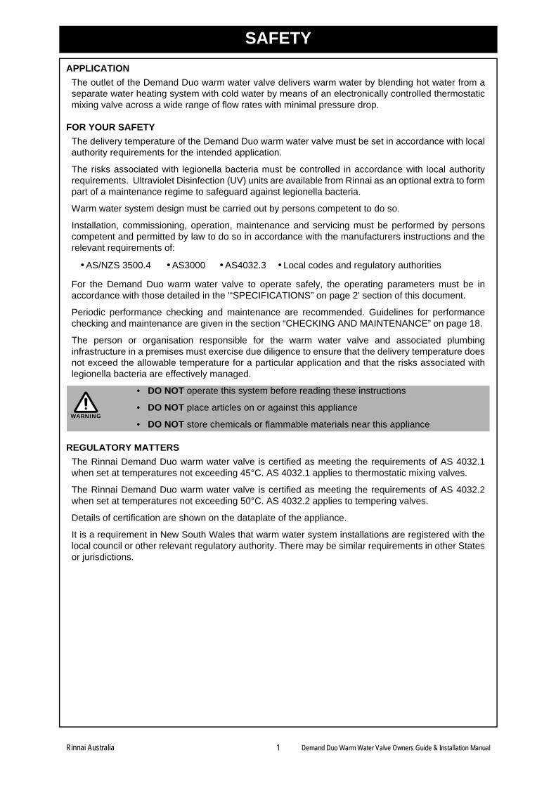
SAFETY
APPLICATION
The outlet of the Demand Duo warm water valve delivers warm water by blending hot water from aseparate water heating system with cold water by means of an electronically controlled thermostaticmixing valve across a wide range of flow rates with minimal pressure drop.
FOR YOUR SAFETY
The delivery temperature of the Demand Duo warm water valve must be set in accordance with localauthority requirements for the intended application.
The risks associated with legionella bacteria must be controlled in accordance with local authorityrequirements. Ultraviolet Disinfection (UV) units are available from Rinnai as an optional extra to formpart of a maintenance regime to safeguard against legionella bacteria.
Warm water system design must be carried out by persons competent to do so.
Installation, commissioning, operation, maintenance and servicing must be performed by personscompetent and permitted by law to do so in accordance with the manufacturers instructions and therelevant requirements of:
For the Demand Duo warm water valve to operate safely, the operating parameters must be inaccordance with those detailed in the '“SPECIFICATIONS” on page 2' section of this document.
Periodic performance checking and maintenance are recommended. Guidelines for performancechecking and maintenance are given in the section “CHECKING AND MAINTENANCE” on page 18.
The person or organisation responsible for the warm water valve and associated plumbinginfrastructure in a premises must exercise due diligence to ensure that the delivery temperature doesnot exceed the allowable temperature for a particular application and that the risks associated withlegionella bacteria are effectively managed.
REGULATORY MATTERS
The Rinnai Demand Duo warm water valve is certified as meeting the requirements of AS 4032.1when set at temperatures not exceeding 45°C. AS 4032.1 applies to thermostatic mixing valves.
The Rinnai Demand Duo warm water valve is certified as meeting the requirements of AS 4032.2when set at temperatures not exceeding 50°C. AS 4032.2 applies to tempering valves.
Details of certification are shown on the dataplate of the appliance.
It is a requirement in New South Wales that warm water system installations are registered with thelocal council or other relevant regulatory authority. There may be similar requirements in other Statesor jurisdictions.
• AS/NZS 3500.4 • AS3000 • AS4032.3 • Local codes and regulatory authorities
• DO NOT operate this system before reading these instructions
• DO NOT place articles on or against this appliance
• DO NOT store chemicals or flammable materials near this appliance WARNING
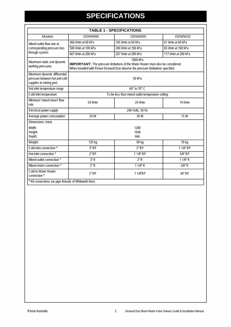
SPECIFICATIONS
TABLE 1 - SPECIFICATIONS
Models DDWW80 DDWW50 DDWW32
Mixed outlet flow rate at corresponding pressure loss through system
360 l/min at 60 kPa 165 l/min at 60 kPa 61 l/min at 60 kPa
500 l/min at 100 kPa 200 l/min at 100 kPa 83 l/min at 100 kPa
667 l/min at 200 kPa 267 l/min at 200 kPa 117 l/min at 200 kPa
Maximum static and dynamic working pressures
1000 kPaIMPORTANT: The pressure limitations of the Water Heater must also be considered. When installed with Rinnai Demand Duo observe the pressure limitations specified.
Maximum dynamic differential pressure between hot and cold supplies to mixing port.
50 kPa
Hot inlet temperature range 60° to 70° C
Cold inlet temperature To be less than mixed outlet temperature setting
Minimum 'mixed return' flow rate
54 l/min 24 l/min 14 l/min
Electrical power supply 240 Volts, 50 Hz
Average power consumption 24 W 20 W 15 W
Dimensions: (mm)
WidthHeight:Depth:
12001640666
Weight: 135 kg 90 kg 70 kg
Cold inlet connection * 3” RP 2” RP 1 1/4” RP
Hot inlet connection * 2” RP 1 1/4” RP 3/4” RP
Mixed outlet connection * 3” R 2” R 1 1/4” R
Mixed return connection * 2” R 1 1/4” R 3/4” R
Cold to Water Heaterconnection *
2” RP 1 1/4”RP 34” RP
* All connections are pipe threads of Whitworth form.
Rinnai Australia 2 Demand Duo Warm Water Valve Owners Guide & Installation Manual
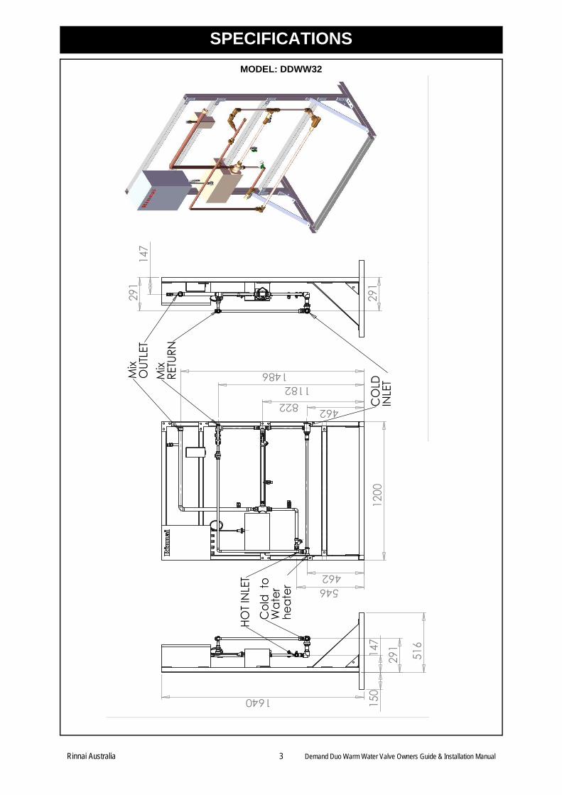
SPECIFICATIONS
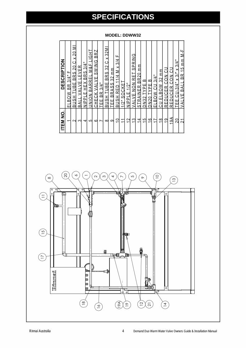
MODEL: DDWW32
462
462546
8221182
1486
1200
147
291
291
516
1640
150
147
291
Mix
OUT
LET
Mix
RETU
RN
CO
LD
INLE
T
HOT I
NLE
TC
old
to
Wat
erhe
ater
Rinnai Australia 3 Demand Duo Warm Water Valve Owners Guide & Installation Manual
SPECIFICATIONS
MODEL: DDWW32
1 2 3 5 9
13
104
14121916
18
1517
11
208
6 719
A
ITEM
NO
.D
ESC
RIP
TIO
N1
ELBO
W B
R 3
/4" F
2BU
SH T
UBE
BR
S 20
C x
20
MI
3BA
LL V
ALVE
LEV
ER4
NIP
PLE
HEX
BR
S 3/
4"5
UN
ION
BAR
REL
M&F
LIG
HT
6C
HEC
K VA
LVE
SWIN
G B
RZ
7TE
E BR
3/4
"8
BUSH
TU
BE B
RS
32 C
x 3
2MI
9TE
E BR
ASS
32 m
m10
BUSH
RED
11/
4 M
x 3
/4 F
111/
2" S
OC
KET
12N
IPPL
E 1/
2"13
VALV
E N
ON
RET
SPR
ING
14ST
RAI
NER
BR
20 m
m15
DN
32 T
YPE
B16
DN
20 T
YPE
B17
ELBO
W C
U 3
/4"
18C
U E
LBO
W 3
2 m
m19
RED
UC
ER C
ON
CU
19A
RED
UC
ER C
ON
CU
20TE
E C
U-3
/4" x
3/"
x 3/
4"21
VALV
E BA
LL B
R 1
5 m
m M
-F
21
Rinnai Australia 4 Demand Duo Warm Water Valve Owners Guide & Installation Manual
SPECIFICATIONS
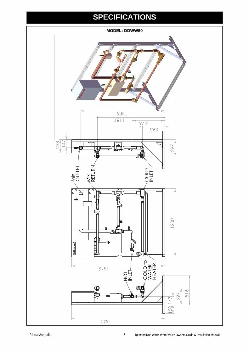
MODEL: DDWW50
1642
1200
29714
7
395
11871485
576
238
150
516
1640
147 29
7
Mix
OUT
LET
Mix
RETU
RN
CO
LD
INLE
T
HOT
INLE
T
CO
LD to
W
ATE
R HE
ATE
R
Rinnai Australia 5 Demand Duo Warm Water Valve Owners Guide & Installation Manual
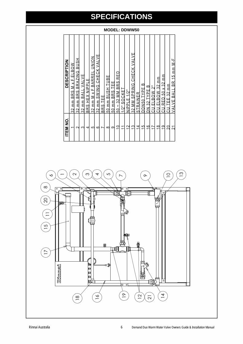
SPECIFICATIONS
MODEL: DDWW50
1 2 5 7 9 10368
1115
4 13
141618
17
19
20
12
ITEM
NO
.D
ESC
RIP
TIO
N1
32 m
m B
RS
M x
F E
LBO
W2
32 m
m B
RS
BRAZ
ING
BU
SH3
32 m
m B
ALL
VALV
E4
BRS
HEX
NIP
PLE
532
mm
M x
F B
ARR
EL U
NIO
N6
32 m
m S
WIN
G C
HEC
K VA
LVE
7BR
S TE
E8
50 m
m B
USH
TU
BE9
50 m
m B
RS
TEE
1050
~ 3
2 M
M B
RS
RED
111/
2" S
OC
KET
12N
IPPL
E 1/
2"13
32 M
M S
PRIN
G C
HEC
K VA
LVE
14ST
RAI
NER
15D
DN
50 T
YPE
B16
DN
32
TYPE
B17
CU
ELB
OW
2"
18C
U E
LBO
W 3
2 m
m19
CU
RED
50
x 32
mm
20C
U T
EE 3
2 m
m21
VALV
E BA
LL B
R 1
5 m
m M
-F
21
Rinnai Australia 6 Demand Duo Warm Water Valve Owners Guide & Installation Manual
SPECIFICATIONS
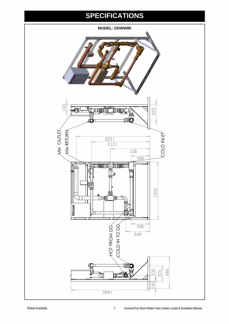
MODEL: DDWW80
1200
385
499
385821
12151533
100
323
666
100
150
1640
323
HOT
FRO
M D
DC
OLD
IN T
O D
D
CO
LD IN
LET
Mix
RETU
RNM
ix O
UTLE
T
Rinnai Australia 7 Demand Duo Warm Water Valve Owners Guide & Installation Manual
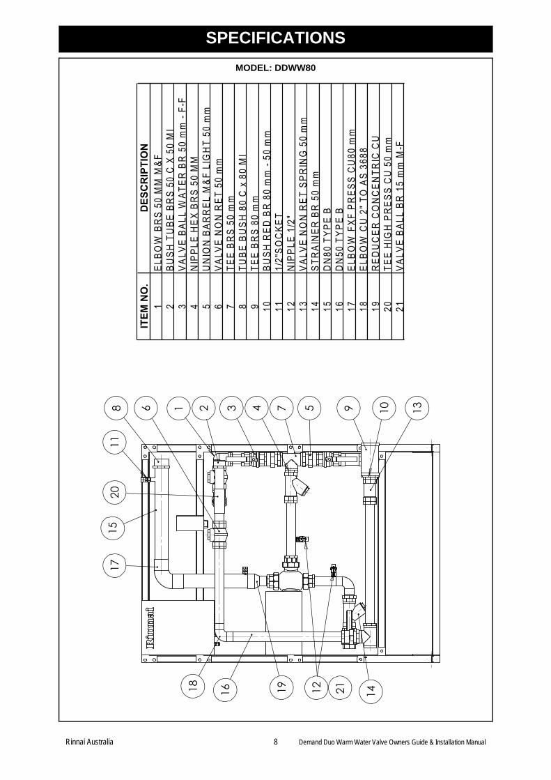
SPECIFICATIONS
MODEL: DDWW80
1 2 3 4 5768 9 10 13
1115
17
18 16 1419
20
ITEM
NO
.D
ESC
RIP
TIO
N1
ELBO
W B
RS
50 M
M M
&F2
BUSH
TU
BE B
RS
50 C
X 5
0 M
I3
VALV
E BA
LL W
ATER
BR
50
mm
- F-
F4
NIP
PLE
HEX
BR
S 50
MM
5U
NIO
N B
ARR
EL M
&F L
IGH
T 50
mm
6VA
LVE
NO
N R
ET 5
0 m
m7
TEE
BRS
50 m
m8
TUBE
BU
SH 8
0 C
x 8
0 M
I9
TEE
BRS
80 m
m10
BUSH
RED
BR
80
mm
- 50
mm
111/
2"SO
CKE
T12
NIP
PLE
1/2"
13VA
LVE
NO
N R
ET S
PRIN
G 5
0 m
m14
STR
AIN
ER B
R 5
0 m
m15
DN
80 T
YPE
B16
DN
50 T
YPE
B17
ELBO
W F
XF P
RES
S C
U80
mm
18EL
BOW
CU
2" T
O A
S 36
8819
RED
UC
ER C
ON
CEN
TRIC
CU
20TE
E H
IGH
PR
ESS
CU
50
mm
21VA
LVE
BALL
BR
15
mm
M-F
12 21
Rinnai Australia 8 Demand Duo Warm Water Valve Owners Guide & Installation Manual
PRINCIPLE OF OPERATION
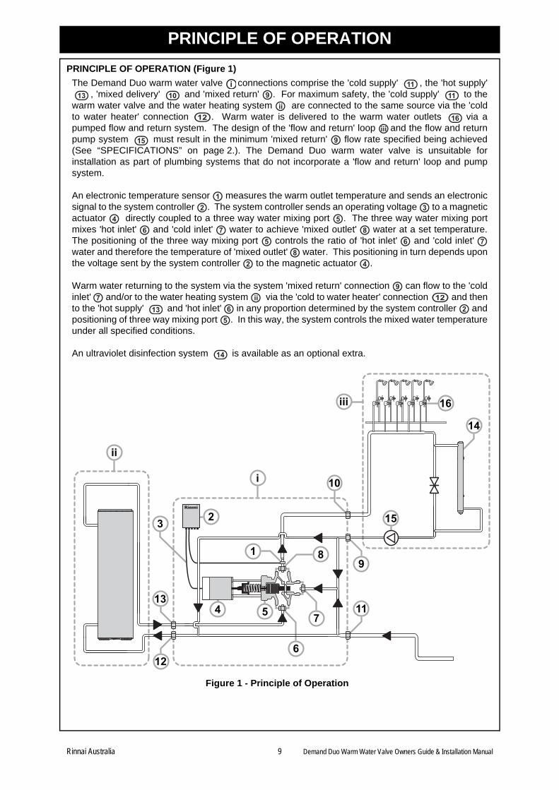
PRINCIPLE OF OPERATION (Figure 1)
The Demand Duo warm water valve connections comprise the 'cold supply' , the 'hot supply', 'mixed delivery' and 'mixed return' . For maximum safety, the 'cold supply' to the
warm water valve and the water heating system are connected to the same source via the 'coldto water heater' connection . Warm water is delivered to the warm water outlets via apumped flow and return system. The design of the 'flow and return' loop and the flow and returnpump system must result in the minimum 'mixed return' flow rate specified being achieved(See “SPECIFICATIONS” on page 2.). The Demand Duo warm water valve is unsuitable forinstallation as part of plumbing systems that do not incorporate a 'flow and return' loop and pumpsystem.
An electronic temperature sensor measures the warm outlet temperature and sends an electronicsignal to the system controller . The system controller sends an operating voltage to a magneticactuator directly coupled to a three way water mixing port . The three way water mixing portmixes 'hot inlet' and 'cold inlet' water to achieve 'mixed outlet' water at a set temperature.The positioning of the three way mixing port controls the ratio of 'hot inlet' and 'cold inlet' water and therefore the temperature of 'mixed outlet' water. This positioning in turn depends uponthe voltage sent by the system controller to the magnetic actuator .
Warm water returning to the system via the system 'mixed return' connection can flow to the 'coldinlet' and/or to the water heating system via the 'cold to water heater' connection and thento the 'hot supply' and 'hot inlet' in any proportion determined by the system controller andpositioning of three way mixing port . In this way, the system controls the mixed water temperatureunder all specified conditions.
An ultraviolet disinfection system is available as an optional extra.
Figure 1 - Principle of Operation
i 1113 10 9 11
ii12 16
iii15 9
12 3
4 56 7 8
5 6 78
2 4
97 ii 12
13 6 25
14
11
6
4 5
2 15
9
12
13
10
8
7
14
3
1
16iii
ii
i
Rinnai Australia 9 Demand Duo Warm Water Valve Owners Guide & Installation Manual
WATER QUALITY
Warranty applies to Demand Duo warm water valves supplied from a reticulated water supply from agovernment water utility. It does not apply if supplied from any alternative water supplies if the waterchemistry and impurity levels of alternative water supplies exceed the limits specified in the separatewarranty booklet. Examples of alternative water supplies include private bore water, water fromprivate dams and water supplied from a reticulated water supply but where the water chemistry isdeliberately altered before supplying the warm water valve.
Warranty terms and conditions are detailed in the separate warranty booklet.
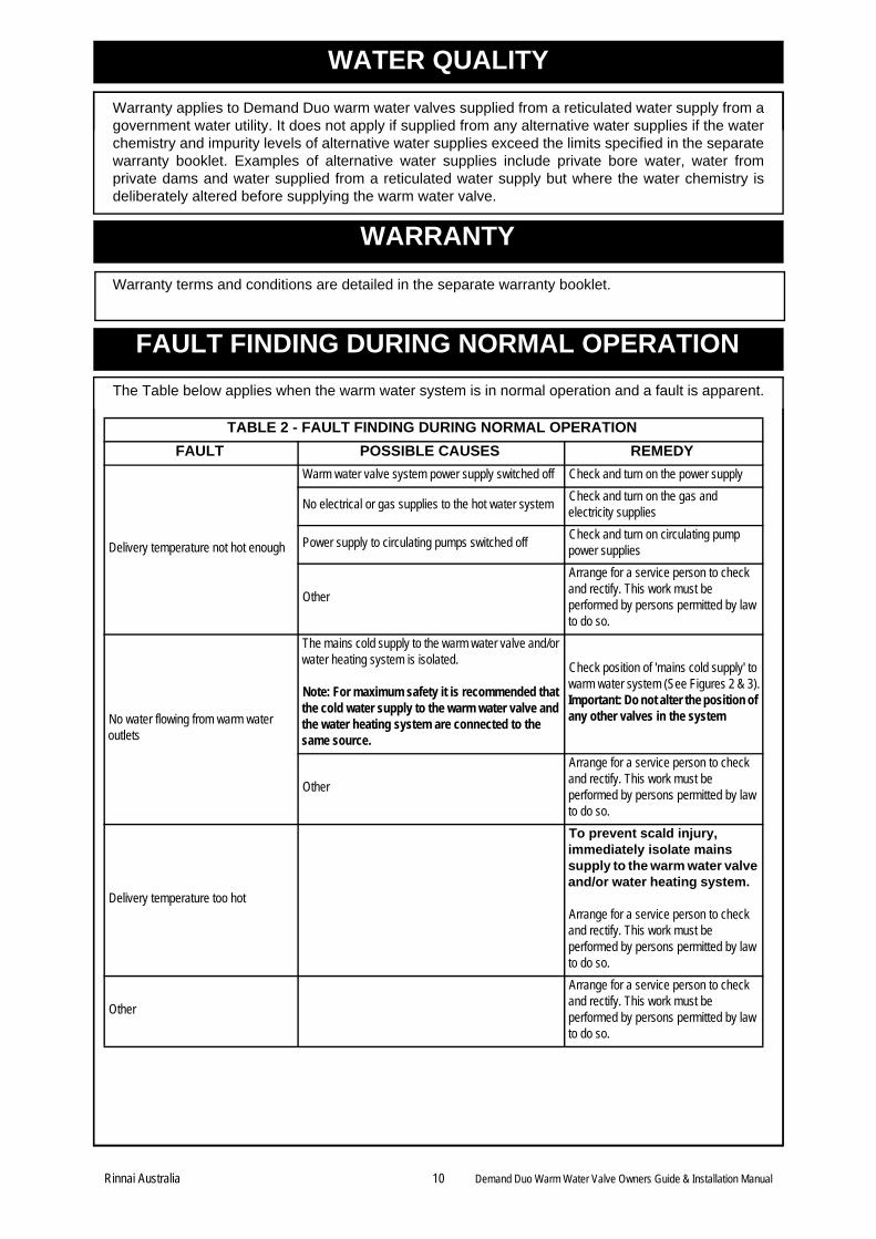
The Table below applies when the warm water system is in normal operation and a fault is apparent.
TABLE 2 - FAULT FINDING DURING NORMAL OPERATION
FAULT POSSIBLE CAUSES REMEDY
Delivery temperature not hot enough
Warm water valve system power supply switched off Check and turn on the power supply
No electrical or gas supplies to the hot water systemCheck and turn on the gas and electricity supplies
Power supply to circulating pumps switched offCheck and turn on circulating pump power supplies
Other
Arrange for a service person to check and rectify. This work must be performed by persons permitted by law to do so.
No water flowing from warm water outlets
The mains cold supply to the warm water valve and/or water heating system is isolated.
Note: For maximum safety it is recommended that the cold water supply to the warm water valve and the water heating system are connected to the same source.
Check position of 'mains cold supply' to warm water system (See Figures 2 & 3).Important: Do not alter the position of any other valves in the system
Other
Arrange for a service person to check and rectify. This work must be performed by persons permitted by law to do so.
Delivery temperature too hot
To prevent scald injury, immediately isolate mains supply to the warm water valve and/or water heating system.
Arrange for a service person to check and rectify. This work must be performed by persons permitted by law to do so.
Other
Arrange for a service person to check and rectify. This work must be performed by persons permitted by law to do so.
WARRANTY
FAULT FINDING DURING NORMAL OPERATION
Rinnai Australia 10 Demand Duo Warm Water Valve Owners Guide & Installation Manual
SYSTEM DESIGN
SYSTEM DESIGN
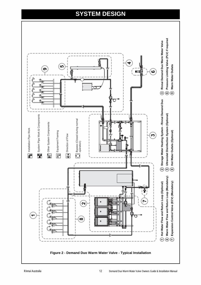
Figures 2 and 3 show a typical installation of a Demand Duo warm water valve with a Demand Duomains pressure gas storage water heating system and associated hot and warm water 'flow andreturn' loops and components. The system consists of the Demand Duo warm water valve , waterheating system , flow and return system piping for warm water , flow and return piping for hotwater (if required) , Ultraviolet disinfection system (optional) interconnection piping and allassociated fittings such as valves, unions and pumps. System design must be carried out by persons competent to do so and must ultimately be such thatthe water temperature at all points is acceptable for the intended application and that legionellabacteria growth can be effectively managed. These considerations are critical. Important design considerations include the following: 1. For maximum safety it is recommended that the cold water supply to the warm water valve
and the water heating system are connected to the same source. To facilitate this, the warmwater valve has a 'cold to water heater' connection . The 'mains cold' supply pipe forboth the warm water valve and water heating system is connected to the 'cold inlet'connection of the warm water valve. The cold water supply to the heated water system is thenprovided via the 'cold to water heater' connection of the warm water valve.
2. To facilitate continuing the warm water supply whilst servicing the Ultraviolet Disinfection unit, awarm water by-pass should be installed as shown. It is recommended to remove the handlefrom the by-pass isolating valve and keep it in a safe place during normal operation to preventunauthorised opening.
3. The number and location of isolating valves in Figures 2 and 3 have been determined soservicing and system checking activities can be carried out efficiently and with minimal disruption.
4. The mains cold supply pipe contains a main isolating valve and pressure limiting valve (if required). The pressure limiting valve must not be located in any other position as this willresult in different hot and cold water supply pressures to the three way mixing port . A'non return' valve is not required to be fitted in the mains cold supply pipe as the warm watervalve already contains all 'non return' valves required for the warm water system to preventbackflow into the cold supply.
5. It is a mandatory requirement that an expansion control valve is fitted. The expansion controlvalve must be located in the pipework between the 'cold supply connection to water heater' from the warm water valve and 'hot inlet’ connection of the water heater . It must not belocated in any other position.
6. The warm water valve and water heater must both be sized for the intended application.
7. Flow and return pipe sizing and configuration and flow and return pump specification must besuch that the following requirements are met:
i. The 'mixed return' flow rate to the warm water valve is equal to or greater than the minimum flow rate specified for the system selected (see “SPECIFICATIONS” on page 2), and
ii.The desired delivery temperature is obtained at any warm water outlet .
8. The Ultraviolet Disinfection system (optional) must be sized for the flow rate through the flowand return system.
9. The maximum dynamic differential pressure between the 'cold inlet' and 'hot inlet' connections to the three way mixing port must not exceed the limit of 50 kPa under all flowconditions (see “SPECIFICATIONS” on page 2). It is desirable that the system design achievesthis without the use of devices such as balancing valves. The length, size and path of thepipework between the warm water valve and the water heating system will greatly influencethe differential pressure achieved.
10. Isolating valves supplied by the installer must be full flow ball or gate valves.
32 4
1 5
A 3
2
3 B A
3 2
C
B
D
A E 6
6
H G O
A
F
F B
3 N
3 2
L
K
9
5
G J
O
3 2
Rinnai Australia 11 Demand Duo Warm Water Valve Owners Guide & Installation Manual
SYSTEM DESIGN
Figure 2 - Demand Duo Warm Water Valve - Typical Installation
Equ
ipm
ent F
ram
ing
Oth
er S
yste
m C
ompo
nent
s
Dire
ctio
n of
Flo
w
Byp
ass
(Clo
sed
durin
g no
rmal
oper
atio
n)
Inst
alla
tion
Pip
e W
ork
Sys
tem
Pip
e W
ork
& C
ompo
nent
s
2
1
5
6
7
9
3
4
8
2St
orag
e W
ater
Hea
ting
Syst
em -
Rin
nai D
eman
d D
uo3
Rin
nai D
eman
d D
uo W
arm
Wat
er V
alve
1H
ot W
ater
Flo
w a
nd R
etur
n Lo
op (O
ptio
nal)
5U
ltrav
iole
t Dis
infe
ctio
n Sy
stem
(Opt
iona
l)6
Pres
sure
Lim
iting
Val
ve (P
LV) i
f req
uire
d4
War
m W
ater
Flo
w a
nd R
etur
n Lo
op (M
anda
tory
)
8H
ot W
ater
Out
lets
(Opt
iona
l)9
War
m W
ater
Out
lets
7Ex
pans
ion
Con
trol
Val
ve (E
CV)
(Man
dato
ry)
Rinnai Australia 12 Demand Duo Warm Water Valve Owners Guide & Installation Manual
SYSTEM DESIGN
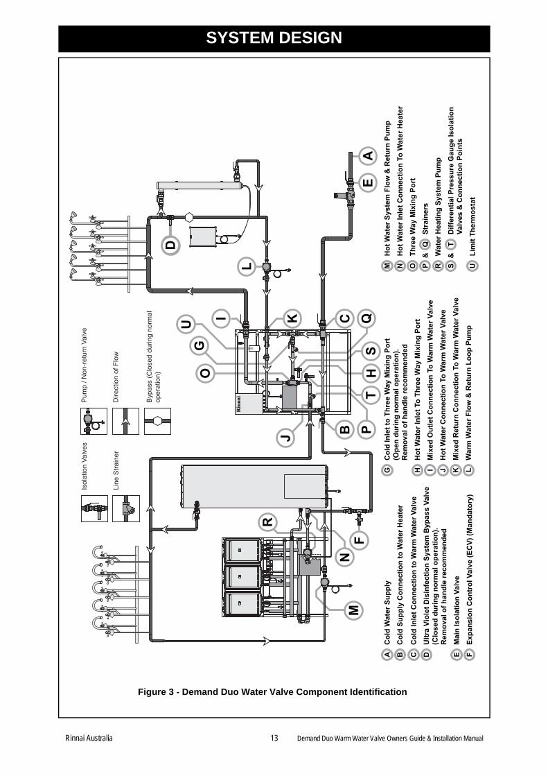
Figure 3 - Demand Duo Water Valve Component Identification
C
J
D
B
H
NM
L
I
EF
K
AQ
ST
P
GO
Isol
atio
n Va
lves
Dire
ctio
n of
Flo
w
Byp
ass
(Clo
sed
durin
g no
rmal
oper
atio
n)
Line
Stra
iner
Pum
p / N
on-r
etur
n Va
lve
R
U
BC
old
Supp
ly C
onne
ctio
n to
Wat
er H
eate
r
CC
old
Inle
t Con
nect
ion
to W
arm
Wat
er V
alve
AC
old
Wat
er S
uppl
y
EM
ain
Isol
atio
n Va
lve
FEx
pans
ion
Con
trol
Val
ve (E
CV)
(Man
dato
ry)
HH
ot W
ater
Inle
t To
Thre
e W
ay M
ixin
g Po
rt
GC
old
Inle
t to
Thre
e W
ay M
ixin
g Po
rt(O
pen
durin
g no
rmal
ope
ratio
n).
Rem
oval
of h
andl
e re
com
men
ded
JH
ot W
ater
Con
nect
ion
To W
arm
Wat
er V
alve
IM
ixed
Out
let C
onne
ctio
n To
War
m W
ater
Val
ve
KM
ixed
Ret
urn
Con
nect
ion
To W
arm
Wat
er V
alve
LW
arm
Wat
er F
low
& R
etur
n Lo
op P
ump
ST
Diff
eren
tial P
ress
ure
Gau
ge Is
olat
ion
Valv
es &
Con
nect
ion
Poin
ts &
ULi
mit
Ther
mos
tat
DU
ltra
Viol
et D
isin
fect
ion
Syst
em B
ypas
s Va
lve
(Clo
sed
durin
g no
rmal
ope
ratio
n).
Rem
oval
of h
andl
e re
com
men
ded
RW
ater
Hea
ting
Syst
em P
ump
MH
ot W
ater
Sys
tem
Flo
w &
Ret
urn
Pum
p
NH
ot W
ater
Inle
t Con
nect
ion
To W
ater
Hea
ter
OTh
ree
Way
Mix
ing
Port
QSt
rain
ers
P &
Rinnai Australia 13 Demand Duo Warm Water Valve Owners Guide & Installation Manual
INSTALLATION
Rinnai Australia 14 Demand Duo Warm Water Valve Owners Guide & Installation Manual
GENERAL INFORMATION
Installation, commissioning, operation, maintenance and service must be performed by personscompetent and permitted by law to do so in accordance with the manufacturers instructions and therelevant requirements of:
The Demand Duo must be installed in accordance with the 'Rinnai Demand Duo Installation Manual'.
It is important that the Installer understands the operational principles of the system beforecommencing installation.
The Demand Duo warm water valve is unsuitable for use in pool heating applications.
For external installations of the Demand Duo warm water valve adequate provisions against ingressof water, wind and sunlight must be made.
Access by unauthorised persons must be prevented.
The Ultraviolet Disinfection system (if fitted) must be installed in accordance with manufacturerinstructions.
LOCATION
The Demand Duo warm water valve should be located in close proximity to the water heater systemto minimise dynamic pressure differences between the hot and cold water inlets to the three waymixing port.
Locate all system components to allow the cold water supply to the warm water valve and the waterheating system to come from the same source. The warm water valve has a 'cold to water heater'connection to facilitate this.
It is recommended that the warm water valve, water heating system and Ultraviolet Disinfectionsystem (if fitted) are installed at ground or floor level. They must be accessible without the use of aladder or scaffold. All components must be accessible for service and removal. With this in mind it isrecommended that a clearance of at least 900 mm is maintained around the perimeter of thesesystems. Installation in roof spaces is not recommended and may contravene local authorityregulations.
The warm water valve control box requires electrical power from a switched AC 240V, 50 Hz, earthedmains power outlet rated at 10 A or higher. The system will not operate without electrical power. Thepower supply cord supplied is 2 metres long.
The Ultraviolet Disinfection system also requires electrical power. Locate the UV system componentsin accordance with manufacturers instructions.
Plan the installation layout of the warm water valve in relation to the water heating system andplumbing infrastructure. Use suitable anchors to secure the warm water valve assembly base to thefloor.
Locate all system components to prevent access by unauthorised persons.
INSTALLATION
Connection sizes are shown in the “SPECIFICATIONS” on page 2. Connections can be made directlyto the warm water valve without the need for disconnection unions as all warm water valve connectionpoints contain wrenching flats. Connections to all other system components must incorporatedisconnection unions.
Flush and clean all water supply pipes before connection.
Install the Demand Duo warm water valve, water heater, flow and return system piping for warm water,flow and return piping for hot water (if required), Ultraviolet disinfection system (if fitted)interconnection piping and associated valves, unions and pump system components.
• AS/NZS 3500.4 • AS3000 • AS4032.3 • Local codes and regulatory authorities
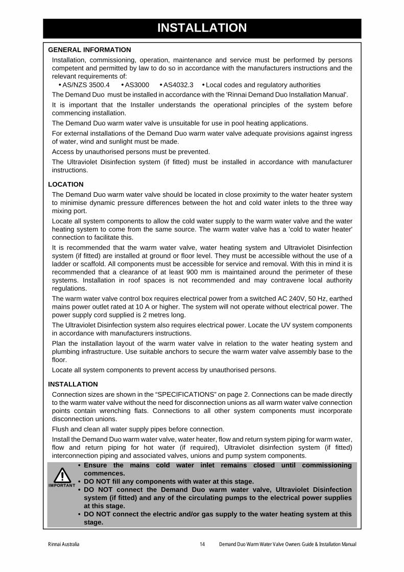
• Ensure the mains cold water inlet remains closed until commissioningcommences.
• DO NOT fill any components with water at this stage. • DO NOT connect the Demand Duo warm water valve, Ultraviolet Disinfection
system (if fitted) and any of the circulating pumps to the electrical power suppliesat this stage.
• DO NOT connect the electric and/or gas supply to the water heating system at thisstage.
IMPORTANT
COMMISSIONING
GENERAL INFORMATION
Commissioning must be performed by persons competent and permitted by law to do so inaccordance with the manufacturers instructions and the relevant requirements of:
During commissioning the system is filled with water and switched on so that water heatingcommences. Commissioning checks are then carried out to set and confirm system performanceparameters under various operating conditions.
FILLING THE SYSTEM
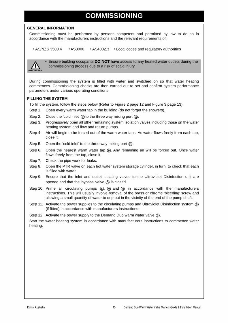
To fill the system, follow the steps below (Refer to Figure 2 page 12 and Figure 3 page 13):
Step 1. Open every warm water tap in the building (do not forget the showers).
Step 2. Close the 'cold inlet' to the three way mixing port .
Step 3. Progressively open all other remaining system isolation valves including those on the waterheating system and flow and return pumps.
Step 4. Air will begin to be forced out of the warm water taps. As water flows freely from each tap,close it.
Step 5. Open the 'cold inlet' to the three way mixing port .
Step 6. Open the nearest warm water tap . Any remaining air will be forced out. Once waterflows freely from the tap, close it.
Step 7. Check the pipe work for leaks.
Step 8. Open the PTR valve on each hot water system storage cylinder, in turn, to check that eachis filled with water.
Step 9. Ensure that the inlet and outlet isolating valves to the Ultraviolet Disinfection unit areopened and that the 'bypass' valve is closed.
Step 10. Prime all circulating pumps , and in accordance with the manufacturersinstructions. This will usually involve removal of the brass or chrome 'bleeding' screw andallowing a small quantity of water to drip out in the vicinity of the end of the pump shaft.
Step 11. Activate the power supplies to the circulating pumps and Ultraviolet Disinfection system (if fitted) in accordance with manufacturers instructions.
Step 12. Activate the power supply to the Demand Duo warm water valve .
Start the water heating system in accordance with manufacturers instructions to commence waterheating.
• AS/NZS 3500.4 • AS3000 • AS4032.3 • Local codes and regulatory authorities
• Ensure building occupants DO NOT have access to any heated water outlets during thecommissioning process due to a risk of scald injury.
IMPORTANT
9 G
G
9
D
L M R
5
3
Rinnai Australia 15 Demand Duo Warm Water Valve Owners Guide & Installation Manual
COMMISSIONING
COMMISSIONING CHECKS
Pre-commissioning Checklist
Before carrying out any commissioning checks, confirm the following:
1. Has it been ensured that building occupants do not have access to any heated water outletsduring the commissioning process?
2. Is the Demand Duo warm water valve installed in accordance with these installation Instructions?
3. Is the water heating system installed and commissioned in accordance with the relevantinstructions?
4. Is the Ultraviolet Disinfection system installed in accordance with the relevant instructions?
5. Has the system been filled with water and has all air been expelled?
6. Has the installation been checked for leaks and have all leaks been rectified?
7. Have the water supply lines been flushed and cleaned?
8. Have the line strainers been cleared?
9. Has the water heating system been switched on and has the hot water temperature reached atleast 60°C?
10. Are system valves and taps opened or closed as required (see “FILLING THE SYSTEM” onpage 15).
11. Is the power supply to the Demand Duo warm water valve switched on?
12. Is the power supply to the Ultraviolet Disinfection system switched on?
13. Are all circulating pumps primed and switched on?
Setting and checking Warm Water Delivery Temperature
The warm water delivery temperature obtainable by the end users must be compatible with theintended application and comply with AS 3500.4 and applicable local regulations and requirements.During commissioning the warm water delivery temperature must be set, checked and adjusted (ifrequired) for every installation as applications and site conditions vary.
The Demand Duo warm water valve is factory pre-set to deliver warm water at a temperature of 43°C. It can be adjusted on site to deliver water at a temperature in the range of 35°C to 55°C. Deliverytemperatures must always be checked using a calibrated thermometer with suitable accuracy andrecorded. The “COMMISSIONING LOG” on page 23 of these instructions can be used for recordingpurposes.
During commissioning set, check and adjust warm water delivery temperature in accordance with theprocedure '“Checking Water Temperature - Full Test” on page 18 as described in the section“PERFORMANCE CHECKING PROCEDURES” on page 18. The procedure “Checking WaterTemperature - Partial Test” on page 19 is not suitable for commissioning purposes.
Checking the warm water delivery temperature obtainable by the end users also forms part of theperformance checking and maintenance procedures outlined in the section “CHECKING ANDMAINTENANCE” on page 18 and should be performed at least once every 12 months.
Differential Pressure Check
The maximum pressure difference between the hot and cold water inlets to the three way mixing portunder flow conditions (dynamic differential pressure) must not exceed 50 kPa for the system toperform as specified (see “SPECIFICATIONS” on page 2). This is checked by connecting a suitabledifferential pressure gauge. Perform the ‘differential pressure check’ procedure as described in thesection “PERFORMANCE CHECKING PROCEDURES” on page 18.
Rinnai Australia 16 Demand Duo Warm Water Valve Owners Guide & Installation Manual
COMMISSIONING
Cold and Hot Water Supply Failure Tests
The cold water supply failure test simulates the failure of cold water supply to the warm waterinstallation whilst a hot water supply still exists. Under these conditions, the system is designed suchthat the three way mixing port closes against the 'hot supply', resulting in stopping the flow to warmwater outlets.
The hot water supply test simulates the failure of hot water supply to the warm water installation whilsta cold water supply still exists. Under these conditions, the system is designed such that the three waymixing port closes against the 'cold supply', resulting in stopping the flow to warm water outlets.
Perform the ‘cold supply failure test’ and ‘hot supply failure test’ as described in the section“PERFORMANCE CHECKING PROCEDURES” on page 18.
Management of Legionella Bacteria Risk during Commissioning
Local regulations and requirements may require that specific activities associated with the riskmanagement of legionella bacteria be carried out before the warm water system is made available foruse. These activities may include disinfecting warm water system pipework, collecting water samplesand having them analysed for legionella bacteria content and the person(s) responsible for the warmwater valve and associated plumbing infrastructure granting permission for the system to be madeavailable for use.
HAND-OVER TO CUSTOMER
After commissioning, the system is ready to be handed over to the customer. Confirm the items onthe checklist below:
1. Confirm that the warm water system and all associated components been commissioned inaccordance with these instructions.
2. Confirm that measurements taken during commissioning have been appropriately recorded (the“COMMISSIONING LOG” on page 23 of these instructions can be used for recording purposes).
3. Remind the customer that the person or organisation responsible for the warm water valve andassociated plumbing infrastructure in a premises must exercise due diligence to ensure that thedelivery temperature does not exceed the allowable temperature for a particular application andthat the risks associated with legionella bacteria are effectively managed. They may need toconform with specific local regulations and requirements in relation to warm water systems andmay require management and maintenance plans to achieve and maintain conformance.
4. Remind the customer of the periodic performance checking and maintenance requirements inthese instructions and that these must be carried out by competent persons who are permitted bylaw to do so.
5. After commissioning it is recommended that the handles for the following valves be removed andkept in a safe place by the person responsible for the warm water valve and associated plumbinginfrastructure in the premises to prevent unauthorised opening or closing:
• Ultraviolet Disinfection System bypass valve
• Cold supply to the three way mixing port
6. It is recommended that the special key for opening the mixing valve controller box is kept awayfrom the warm water valve in a safe place by the person responsible for the warm water valveand associated plumbing infrastructure to prevent unauthorised opening and adjustment.
7. Hand the Commissioning Log to the customer and retain a copy for yourself for future reference.
8. Hand this manual to the customer and remind them to put it in a safe and accessible place forfuture reference.
Rinnai Australia 17 Demand Duo Warm Water Valve Owners Guide & Installation Manual
CHECKING AND MAINTENANCE
Rinnai Australia 18 Demand Duo Warm Water Valve Owners Guide & Installation Manual
GENERAL INFORMATION
It is a requirement in New South Wales that warm water system installations are registered with thelocal council or other relevant regulatory authority. There may be similar requirements in other States.
The Demand Duo Warm Water Valve contains sophisticated and precision engineered componentsand should provide many years of safe and reliable service provided it is installed, commissioned,operated and maintained in accordance with these instructions.
It is recommended that the performance checking and maintenance procedures in these instructionsare carried out and recorded at least once every 12 months. This frequency is intended as a guideonly and may need to be varied depending on site specific operational conditions and any localregulations and requirements. As an example, in healthcare installations the risks to users aregenerally higher than those in non healthcare installations and this would warrant more frequentperformance checking and maintenance in healthcare installations.
For specific information regarding checking and maintenance of the Ultraviolet Disinfection systemrefer to the manufacturers instructions.
Performance checking and maintenance must be performed by competent personnel. The “MAINTENANCE LOG” on page 24 of these instructions can be used for recording purposes.
PERFORMANCE CHECKING PROCEDURES
Checking Water Temperature - Full Test
This test must be performed during commissioning for every installation. If carrying out this test as partof commissioning ensure you have read and fully understood the section “Setting and checking WarmWater Delivery Temperature” on page 16.
This test is also recommended for routine checking of water temperature as part of the performancechecking and maintenance regime.
This test is carried out at both full and partial flow rates.
Step 1. NOTE: This step is carried out during commissioning only. It is not carried out duringroutine checking and maintenance. Set the delivery temperature of the warm water valve inaccordance with the procedure “Checking Water Temperature - Partial Test” on page 19.
Step 2. Open sufficient warm water outlets within the warm water flow and return loop toachieve the design ‘peak flow rate’ of the warm water installation. This is usually 20-30% ofthe total number of warm water outlets. If in doubt consult the system designer.
Step 3. Check and record the temperature at the outlet nearest to the mixed outlet connection ofthe warm water valve.
Step 4. Close all warm water outlets. Step 5. Open the warm water outlet furthest from the mixed outlet connection of the warm water
valve. DO NOT open any other warm water outlets. Check and record the temperature. Step 6. Adjust delivery temperature in accordance with the section “Checking Water Temperature -
Partial Test” on page 19.Step 7. Repeat steps 2 to 6 as required. Step 8. If the delivery temperature cannot be adjusted to the desired temperature refer to the
section “Fault Finding During Performance Checking” on page 22.
Checking the Limit Thermostat and probe bellows
The Limit Thermostat is shown as item on Figure 3, page 13. The temperature probe for the limitthermostat is located in the ‘mixed outlet. The limit thermostat and temperature probe perform acritical safety function. When activated, it results in the 3 way mixing port being closed against the hotsupply and therefore a ‘safe’ warm outlet temperature. It activates only when the mixed outlettemperature reaches the ‘set point’ of the limit thermostat. This set point is reached only when thedeliver temperature exceeds the normal operating range which occurs only during operator error orsevere failure of critical components in the warm water installation.
The ‘set point’ of the limit thermostat is factory set. It must not be altered duringcommissioning. Ensure that the bellows (copper tube) between the limit thermostat housing andtemperature probe is connected and undamaged.
9
U
IMPORTANT
CHECKING AND MAINTENANCE
Checking Water Temperature - Partial Test
This test is not suitable for commissioning purposes. It is carried out at low flow rate only. It is suitablefor use only during routine checking of water temperature when it is impracticable to open all warmwater outlets and achieve full flow through the system. The 'Full Test' described above is always thepreferred method for checking water temperature.
Step 1. Open the warm water outlet nearest to the mixed outlet connection of the warm water valveand check and record the temperature. Close this outlet.
Step 2. Open the warm water outlet furthest from the mixed outlet connection of the warm watervalve. Check and record the temperature. Close this outlet.
Step 3. If the delivery temperature is incorrect, the 'Checking water temperature - full test' must beperformed and the delivery temperature adjusted accordingly.
Step 4. If the delivery temperature cannot be adjusted correctly refer to the section 'PerformanceChecking Fault Finding'.
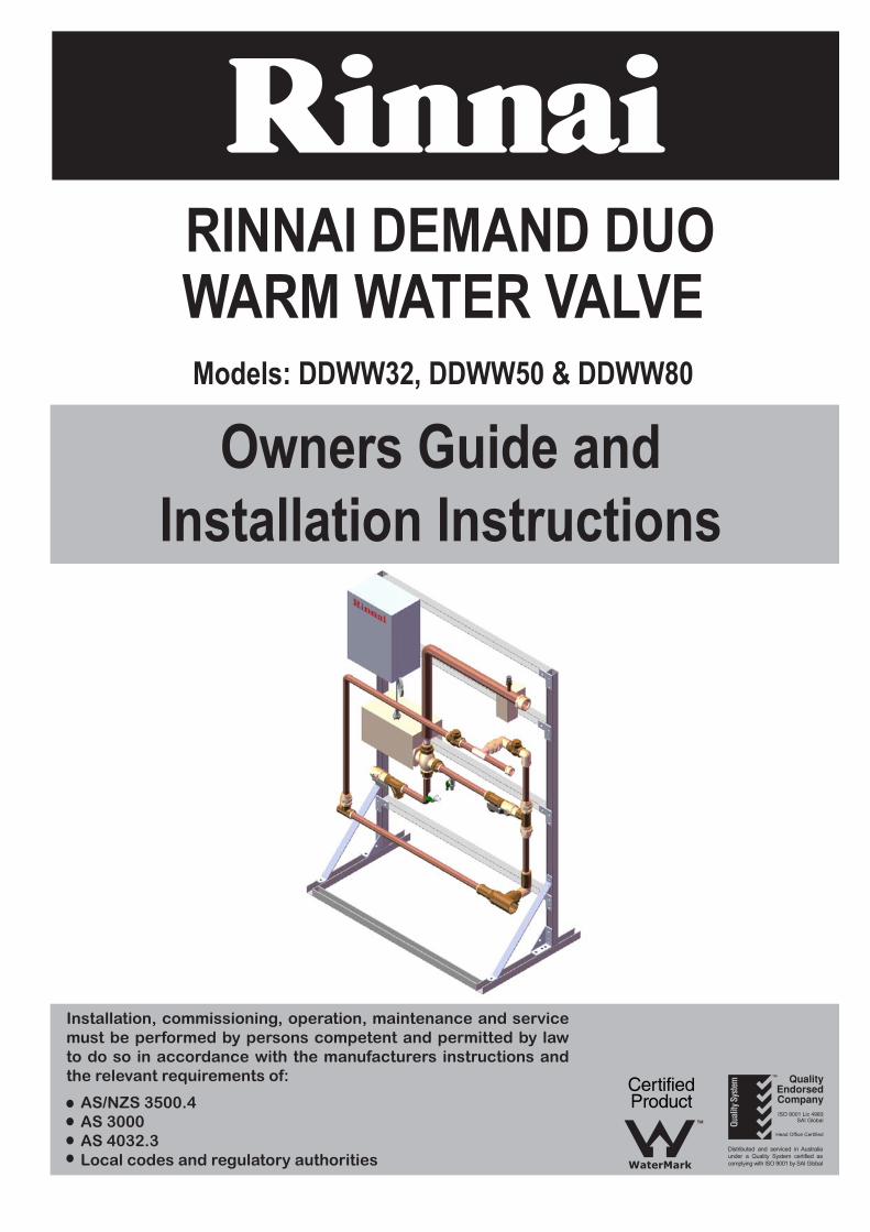
Delivery Temperature Adjustment
Delivery temperature adjustment must only be carried out after performing the “Checking WaterTemperature - Full Test” on page 18.
The delivery temperature obtainable by the end users must be compatible with the intendedapplication and comply with AS 3500.4 and applicable local regulations and requirements. The warmwater valve controller is factory pre-set to deliver warm water at a temperature of 43°C. It can beadjusted on site to deliver water at a temperature in the range of 35°C to 55°C in accordance with thisprocedure.
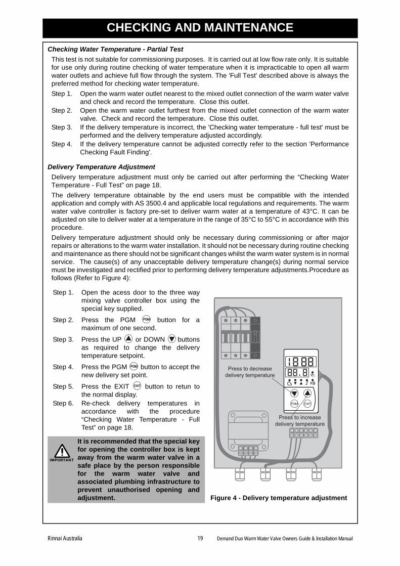
Delivery temperature adjustment should only be necessary during commissioning or after majorrepairs or alterations to the warm water installation. It should not be necessary during routine checkingand maintenance as there should not be significant changes whilst the warm water system is in normalservice. The cause(s) of any unacceptable delivery temperature change(s) during normal servicemust be investigated and rectified prior to performing delivery temperature adjustments.Procedure asfollows (Refer to Figure 4):
Step 1. Open the acess door to the three waymixing valve controller box using thespecial key supplied.
Step 2. Press the PGM button for amaximum of one second.
Step 3. Press the UP or DOWN buttonsas required to change the deliverytemperature setpoint.
Step 4. Press the PGM button to accept thenew delivery set point.
Step 5. Press the EXIT button to retun tothe normal display.
Step 6. Re-check delivery temperatures inaccordance with the procedure“Checking Water Temperature - FullTest” on page 18.
Figure 4 - Delivery temperature adjustment
It is recommended that the special keyfor opening the controller box is keptaway from the warm water valve in asafe place by the person responsiblefor the warm water valve andassociated plumbing infrastructure toprevent unauthorised opening andadjustment.
Press to decreasedelivery temperature
Press to increasedelivery temperature
IMPORTANT
Rinnai Australia 19 Demand Duo Warm Water Valve Owners Guide & Installation Manual
CHECKING AND MAINTENANCE
Differential Pressure Check
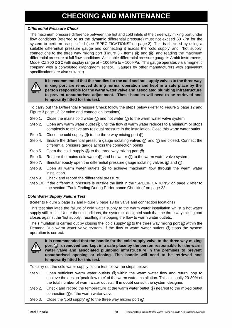
The maximum pressure difference between the hot and cold inlets of the three way mixing port underflow conditions (referred to as the dynamic differential pressure) must not exceed 50 kPa for thesystem to perform as specified (see “SPECIFICATIONS” on page 2). This is checked by using asuitable differential pressure gauge and connecting it across the 'cold supply' and 'hot supply'connections to the three way mixing port (Figure 3 - Items and ) and reading the maximumdifferential pressure at full flow conditions. A suitable differential pressure gauge is Ambit Instruments,Model CZ 300 DGC with display range of – 100 kPa to + 100 kPa. This gauge operates via a magneticcoupling with a convoluted diaphgragm sensor. Gauges by other manufacturers with equivalentspecifications are also suitable).
To carry out the Differential Pressure Check follow the steps below (Refer to Figure 2 page 12 andFigure 3 page 13 for valve and connection locations).
Step 1. Close the mains cold water and hot water to the warm water valve system
Step 2. Open any warm water outlet until the flow of warm water reduces to a minimum or stopscompletely to relieve any residual pressure in the installation. Close this warm water outlet.
Step 3. Close the cold supply to the three way mixing port .
Step 4. Ensure the differential pressure gauge isolating valves and are closed. Connect thedifferential pressure gauge across the connection points
Step 5. Open the cold supply to the three way mixing port .
Step 6. Restore the mains cold water and hot water to the warm water valve system.
Step 7. Simultaneously open the differential pressure gauge isolating valves and .
Step 8. Open all warm water outlets to achieve maximum flow through the warm waterinstallation.
Step 9. Check and record the differential pressure. Step 10. If the differential pressure is outside the limit in the “SPECIFICATIONS” on page 2 refer to
the section “Fault Finding During Performance Checking” on page 22.
Cold Water Supply Failure Test
(Refer to Figure 2 page 12 and Figure 3 page 13 for valve and connection locations)
This test simulates the failure of cold water supply to the warm water installation whilst a hot watersupply still exists. Under these conditions, the system is designed such that the three way mixing portcloses against the 'hot supply', resulting in stopping the flow to warm water outlets.
The simulation is carried out by closing the 'cold supply' to the three way mixing port within theDemand Duo warm water valve system. If the flow to warm water outlets stops the systemoperation is correct.
To carry out the cold water supply failure test follow the steps below:
Step 1. Open sufficient warm water outlets within the warm water flow and return loop toachieve the design ‘peak flow rate’ of the warm water installation. This is usually 20-30% ofthe total number of warm water outlets. If in doubt consult the system designer.
Step 2. Check and record the temperature at the warm water outlet nearest to the mixed outletconnection of the warm water valve.
Step 3. Close the 'cold supply' to the three way mixing port .
It is recommended that the handles for the cold and hot supply valves to the three waymixing port are removed during normal operation and kept in a safe place by theperson responsible for the warm water valve and associated plumbing infrastructureto prevent unauthorised adjustment. These handles will need to be retrieved andtemporarily fitted for this test.
It is recommended that the handle for the cold supply valve to the three way mixingport is removed and kept in a safe place by the person responsible for the warmwater valve and associated plumbing infrastructure in the premises to preventunauthorised opening or closing. This handle will need to be retrieved andtemporarily fitted for this test.
G H
NOTE
C J
9
G O
S T
G O
C J
S T
9
G O9
NOTE
G
9
9
I
G O
Rinnai Australia 20 Demand Duo Warm Water Valve Owners Guide & Installation Manual
CHECKING AND MAINTENANCE
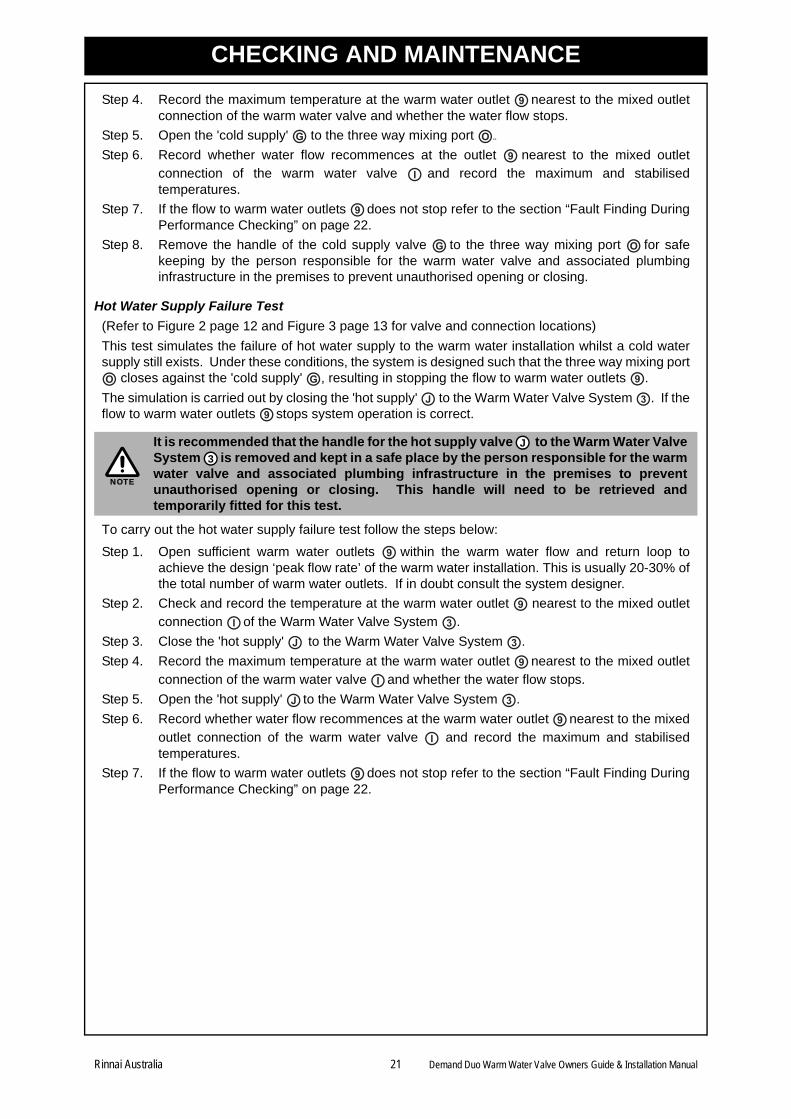
Step 4. Record the maximum temperature at the warm water outlet nearest to the mixed outletconnection of the warm water valve and whether the water flow stops.
Step 5. Open the 'cold supply' to the three way mixing port ..
Step 6. Record whether water flow recommences at the outlet nearest to the mixed outletconnection of the warm water valve and record the maximum and stabilisedtemperatures.
Step 7. If the flow to warm water outlets does not stop refer to the section “Fault Finding DuringPerformance Checking” on page 22.
Step 8. Remove the handle of the cold supply valve to the three way mixing port for safekeeping by the person responsible for the warm water valve and associated plumbinginfrastructure in the premises to prevent unauthorised opening or closing.
Hot Water Supply Failure Test
(Refer to Figure 2 page 12 and Figure 3 page 13 for valve and connection locations)
This test simulates the failure of hot water supply to the warm water installation whilst a cold watersupply still exists. Under these conditions, the system is designed such that the three way mixing port
closes against the 'cold supply' , resulting in stopping the flow to warm water outlets .
The simulation is carried out by closing the 'hot supply' to the Warm Water Valve System . If theflow to warm water outlets stops system operation is correct.
To carry out the hot water supply failure test follow the steps below:
Step 1. Open sufficient warm water outlets within the warm water flow and return loop toachieve the design ‘peak flow rate’ of the warm water installation. This is usually 20-30% ofthe total number of warm water outlets. If in doubt consult the system designer.
Step 2. Check and record the temperature at the warm water outlet nearest to the mixed outletconnection of the Warm Water Valve System .
Step 3. Close the 'hot supply' to the Warm Water Valve System .
Step 4. Record the maximum temperature at the warm water outlet nearest to the mixed outletconnection of the warm water valve and whether the water flow stops.
Step 5. Open the 'hot supply' to the Warm Water Valve System .
Step 6. Record whether water flow recommences at the warm water outlet nearest to the mixedoutlet connection of the warm water valve and record the maximum and stabilisedtemperatures.
Step 7. If the flow to warm water outlets does not stop refer to the section “Fault Finding DuringPerformance Checking” on page 22.
It is recommended that the handle for the hot supply valve to the Warm Water ValveSystem is removed and kept in a safe place by the person responsible for the warmwater valve and associated plumbing infrastructure in the premises to preventunauthorised opening or closing. This handle will need to be retrieved andtemporarily fitted for this test.
9
G O
9
I
9
G O
O G 9
J 39
NOTE
J
3
9
9
I 3
J 3
9
I
J 3
9
I
9
Rinnai Australia 21 Demand Duo Warm Water Valve Owners Guide & Installation Manual
CHECKING AND MAINTENANCE
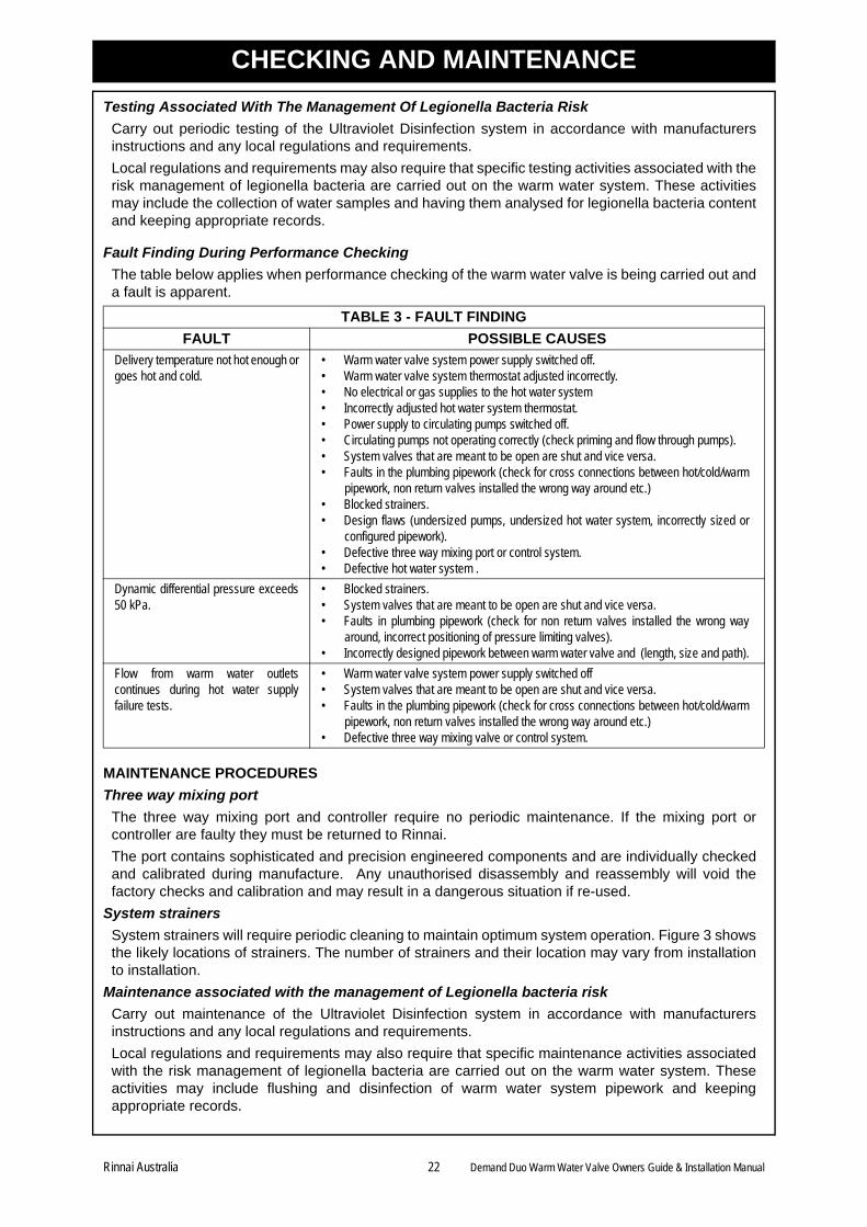
Testing Associated With The Management Of Legionella Bacteria Risk
Carry out periodic testing of the Ultraviolet Disinfection system in accordance with manufacturersinstructions and any local regulations and requirements.
Local regulations and requirements may also require that specific testing activities associated with therisk management of legionella bacteria are carried out on the warm water system. These activitiesmay include the collection of water samples and having them analysed for legionella bacteria contentand keeping appropriate records.
Fault Finding During Performance Checking
The table below applies when performance checking of the warm water valve is being carried out anda fault is apparent.
MAINTENANCE PROCEDURES
Three way mixing port
The three way mixing port and controller require no periodic maintenance. If the mixing port orcontroller are faulty they must be returned to Rinnai.
The port contains sophisticated and precision engineered components and are individually checkedand calibrated during manufacture. Any unauthorised disassembly and reassembly will void thefactory checks and calibration and may result in a dangerous situation if re-used.
System strainers
System strainers will require periodic cleaning to maintain optimum system operation. Figure 3 showsthe likely locations of strainers. The number of strainers and their location may vary from installationto installation.
Maintenance associated with the management of Legionella bacteria risk
Carry out maintenance of the Ultraviolet Disinfection system in accordance with manufacturersinstructions and any local regulations and requirements.
Local regulations and requirements may also require that specific maintenance activities associatedwith the risk management of legionella bacteria are carried out on the warm water system. Theseactivities may include flushing and disinfection of warm water system pipework and keepingappropriate records.
TABLE 3 - FAULT FINDING
FAULT POSSIBLE CAUSES
Delivery temperature not hot enough orgoes hot and cold.
• Warm water valve system power supply switched off. • Warm water valve system thermostat adjusted incorrectly.• No electrical or gas supplies to the hot water system • Incorrectly adjusted hot water system thermostat.• Power supply to circulating pumps switched off.• Circulating pumps not operating correctly (check priming and flow through pumps).• System valves that are meant to be open are shut and vice versa.• Faults in the plumbing pipework (check for cross connections between hot/cold/warm
pipework, non return valves installed the wrong way around etc.) • Blocked strainers.• Design flaws (undersized pumps, undersized hot water system, incorrectly sized or
configured pipework).• Defective three way mixing port or control system.• Defective hot water system .
Dynamic differential pressure exceeds50 kPa.
• Blocked strainers. • System valves that are meant to be open are shut and vice versa. • Faults in plumbing pipework (check for non return valves installed the wrong way
around, incorrect positioning of pressure limiting valves).• Incorrectly designed pipework between warm water valve and (length, size and path).
Flow from warm water outletscontinues during hot water supplyfailure tests.
• Warm water valve system power supply switched off • System valves that are meant to be open are shut and vice versa. • Faults in the plumbing pipework (check for cross connections between hot/cold/warm
pipework, non return valves installed the wrong way around etc.) • Defective three way mixing valve or control system.
Rinnai Australia 22 Demand Duo Warm Water Valve Owners Guide & Installation Manual
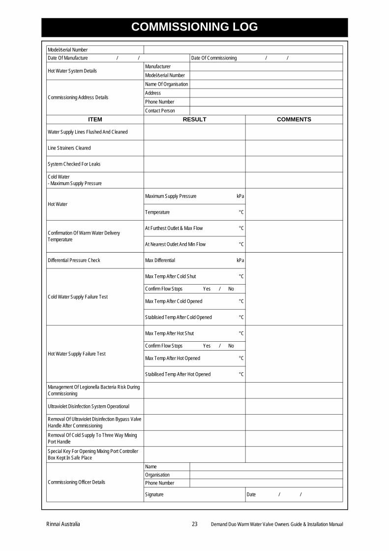
COMMISSIONING LOG
Model/serial Number
Date Of Manufacture / / Date Of Commissioning / /
Hot Water System DetailsManufacturer
Model/serial Number
Commissioning Address Details
Name Of Organisation
Address
Phone Number
Contact Person
ITEM RESULT COMMENTS
Water Supply Lines Flushed And Cleaned
Line Strainers Cleared
System Checked For Leaks
Cold Water - Maximum Supply Pressure
Hot Water
Maximum Supply Pressure kPa
Temperature °C
Confirmation Of Warm Water Delivery Temperature
At Furthest Outlet & Max Flow °C
At Nearest Outlet And Min Flow °C
Differential Pressure Check Max Differential kPa
Cold Water Supply Failure Test
Max Temp After Cold Shut °C
Confirm Flow Stops Yes / No
Max Temp After Cold Opened °C
Stablisied Temp After Cold Opened °C
Hot Water Supply Failure Test
Max Temp After Hot Shut °C
Confirm Flow Stops Yes / No
Max Temp After Hot Opened °C
Stabilised Temp After Hot Opened °C
Management Of Legionella Bacteria Risk During Commissioning
Ultraviolet Disinfection System Operational
Removal Of Ultraviolet Disinfection Bypass Valve Handle After Commissioning
Removal Of Cold Supply To Three Way Mixing Port Handle
Special Key For Opening Mixing Port Controller Box Kept In Safe Place
Commissioning Officer Details
Name
Organisation
Phone Number
Signature Date / /
Rinnai Australia 23 Demand Duo Warm Water Valve Owners Guide & Installation Manual
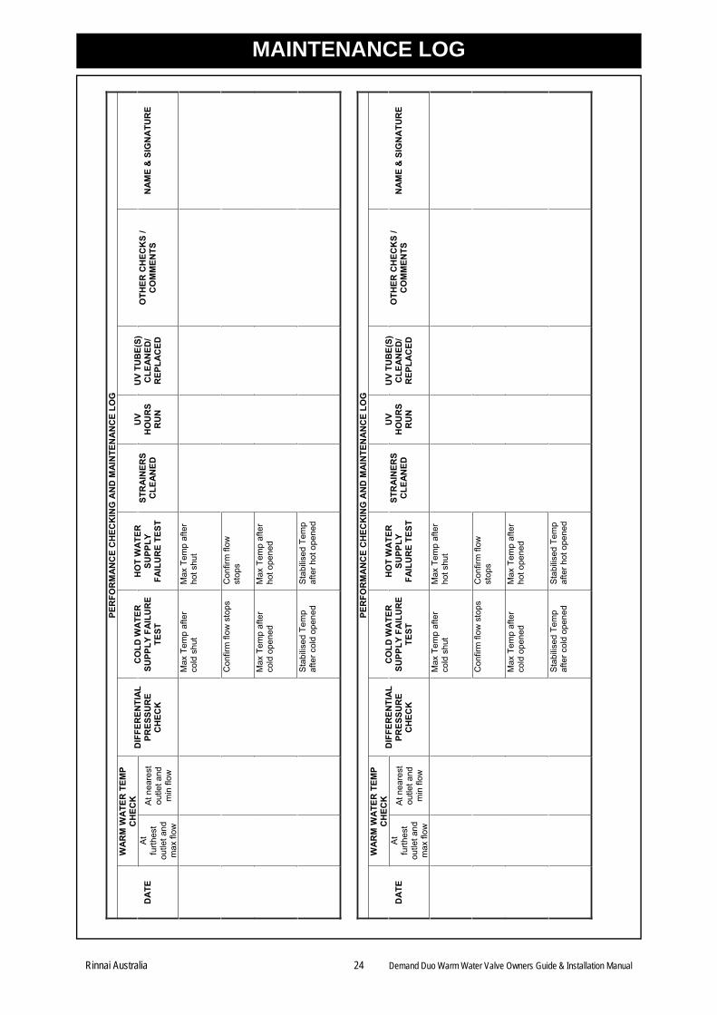
MAINTENANCE LOG
PER
FOR
MA
NC
E C
HEC
KIN
G A
ND
MA
INTE
NA
NC
E LO
G
WA
RM
WA
TER
TEM
P C
HEC
KD
ATE
A
tfu
rthes
tou
tlet a
nd
max
flow
At n
eare
st
outle
t and
m
in fl
ow
DIF
FER
ENTI
AL
PRES
SUR
EC
HEC
K
CO
LD W
ATE
R
SUPP
LY F
AIL
UR
E TE
ST
HO
T W
ATE
R
SUPP
LYFA
ILU
RE
TEST
STR
AIN
ERS
CLE
AN
ED
UV
HO
UR
S R
UN
UV
TUB
E(S)
C
LEA
NED
/ R
EPLA
CED
OTH
ER C
HEC
KS
/ C
OM
MEN
TS
NA
ME
& S
IGN
ATU
RE
Max
Tem
p af
ter
cold
shu
tM
ax T
emp
afte
r ho
t shu
t
Con
firm
flow
sto
ps
Con
firm
flow
st
ops
Max
Tem
p af
ter
cold
ope
ned
Max
Tem
p af
ter
hot o
pene
d
Sta
bilis
ed T
emp
afte
r col
d op
ened
S
tabi
lised
Tem
p af
ter h
ot o
pene
d
PER
FOR
MA
NC
E C
HEC
KIN
G A
ND
MA
INTE
NA
NC
E LO
G
WA
RM
WA
TER
TEM
P C
HEC
KD
ATE
A
tfu
rthes
tou
tlet a
nd
max
flow
At n
eare
st
outle
t and
m
in fl
ow
DIF
FER
ENTI
AL
PRES
SUR
EC
HEC
K
CO
LD W
ATE
R
SUPP
LY F
AIL
UR
E TE
ST
HO
T W
ATE
R
SUPP
LYFA
ILU
RE
TEST
ST
RA
INER
S C
LEA
NED
U
VH
OU
RS
RU
N
UV
TUB
E(S)
C
LEA
NED
/ R
EPLA
CED
O
THER
CH
ECK
S /
CO
MM
ENTS
N
AM
E &
SIG
NA
TUR
E
Max
Tem
p af
ter
cold
shu
tM
ax T
emp
afte
r ho
t shu
t
Con
firm
flow
sto
ps
Con
firm
flow
st
ops
Max
Tem
p af
ter
cold
ope
ned
Max
Tem
p af
ter
hot o
pene
d
Sta
bilis
ed T
emp
afte
r col
d op
ened
S
tabi
lised
Tem
p af
ter h
ot o
pene
d
Rinnai Australia 24 Demand Duo Warm Water Valve Owners Guide & Installation Manual
Rinnai Australia 25Demand Duo Warm Water Valve Owners Guide & Inst - Issue No.2 14/10/09
CONTACTS
Head Office 10-11 Walker Street,Braeside, Victoria 3195P.O. Box 460Tel: (03) 9271 6625Fax: (03) 9271 6622
National Help LinesSales & Service Tel: 1300 555 545* Fax: 1300 555 655*Spare Parts & Technical InfoTel: 1300 366 388* Fax: 1300 300 141**Cost of a local call Higher from mobile or public phones.
Australia Pty. Ltd. ABN 74 005 138 769 Internet: www.rinnai.com.au E-mail: [email protected]