Embed Size (px)
DESCRIPTION
Tankless Water Heater Product Knowledge
Citation preview
www.rinnai.us • © 2011 Rinnai Corporation
Tankless Water Heater Training Program
Product Knowledge
Level I
WH Trng Prg Level I – Course #801101
040811
www.rinnai.us • © 2011 Rinnai Corporation
PROMOTIONAL VIDEOS
Heat all the water you need,
only when you need it.
Positively Georgia: Rinnai
tankless water heaters
provide energy-efficient,
endless hot water to
Operation Mobilization.
Make the most of your time in
the shower with a Rinnai
tankless water heater.
Positively Georgia: Save
money, save space and
enjoy cleaner hot water with
a Rinnai tankless water
heater.
Positively Georgia: Rinnai
helps in local efforts to raise
money and bring awareness
to Cystic Fibrosis.
Rinnai Water Heater
Technical Training
www.rinnai.us • © 2011 Rinnai Corporation 3
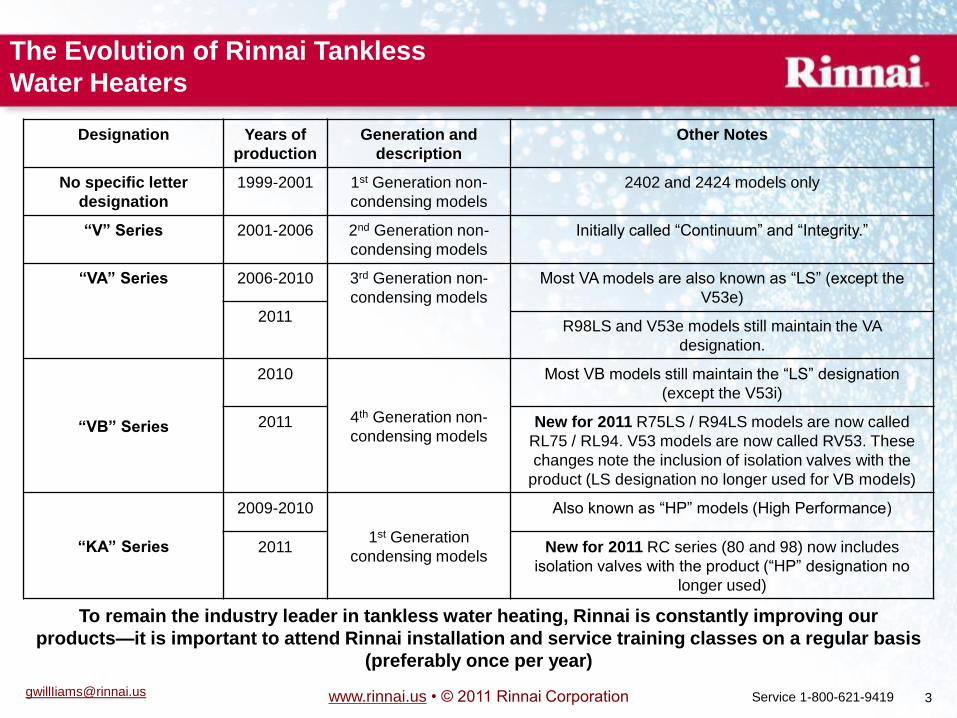
Designation Years of
production
Generation and
description
Other Notes
No specific letter
designation
1999-2001 1st Generation non-
condensing models
2402 and 2424 models only
―V‖ Series 2001-2006 2nd Generation non-
condensing models
Initially called ―Continuum‖ and ―Integrity.‖
―VA‖ Series 2006-2010 3rd Generation non-
condensing models
Most VA models are also known as ―LS‖ (except the
V53e)
2011 R98LS and V53e models still maintain the VA
designation.
―VB‖ Series
2010
4th Generation non-
condensing models
Most VB models still maintain the ―LS‖ designation
(except the V53i)
2011 New for 2011 R75LS / R94LS models are now called
RL75 / RL94. V53 models are now called RV53. These
changes note the inclusion of isolation valves with the
product (LS designation no longer used for VB models)
―KA‖ Series
2009-2010
1st Generation
condensing models
Also known as ―HP‖ models (High Performance)
2011 New for 2011 RC series (80 and 98) now includes
isolation valves with the product (―HP‖ designation no
longer used)
The Evolution of Rinnai Tankless
Water Heaters
To remain the industry leader in tankless water heating, Rinnai is constantly improving our
products—it is important to attend Rinnai installation and service training classes on a regular basis
(preferably once per year)
[email protected] Service 1-800-621-9419
www.rinnai.us • © 2011 Rinnai Corporation 4
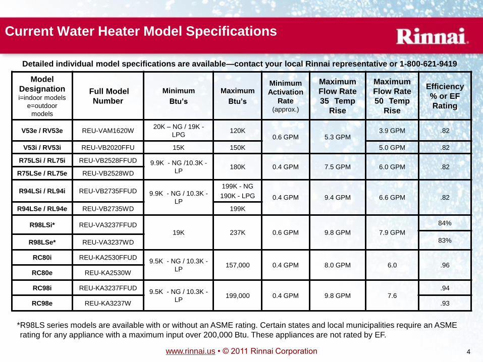
Model
Designation i=indoor models
e=outdoor
models
Full Model
Number
Minimum
Btu’s
Maximum
Btu’s
Minimum
Activation
Rate (approx.)
Maximum
Flow Rate
35
Temp
Rise
Maximum
Flow Rate
50
Temp
Rise
Efficiency
% or EF
Rating
V53e / RV53e REU-VAM1620W 20K – NG / 19K -
LPG 120K
0.6 GPM 5.3 GPM 3.9 GPM .82
V53i / RV53i REU-VB2020FFU 15K 150K 5.0 GPM .82
R75LSi / RL75i REU-VB2528FFUD 9.9K - NG /10.3K -
LP 180K 0.4 GPM 7.5 GPM 6.0 GPM .82
R75LSe / RL75e REU-VB2528WD
R94LSi / RL94i REU-VB2735FFUD 9.9K - NG / 10.3K -
LP
199K - NG
190K - LPG 0.4 GPM 9.4 GPM 6.6 GPM .82
R94LSe / RL94e REU-VB2735WD 199K
R98LSi* REU-VA3237FFUD 19K 237K 0.6 GPM 9.8 GPM 7.9 GPM
84%
83% R98LSe* REU-VA3237WD
RC80i REU-KA2530FFUD 9.5K - NG / 10.3K -
LP 157,000 0.4 GPM 8.0 GPM 6.0 .96
RC80e REU-KA2530W
RC98i REU-KA3237FFUD 9.5K - NG / 10.3K -
LP 199,000 0.4 GPM 9.8 GPM 7.6
.94
RC98e REU-KA3237W .93
*R98LS series models are available with or without an ASME rating. Certain states and local municipalities require an ASME
rating for any appliance with a maximum input over 200,000 Btu. These appliances are not rated by EF.
Detailed individual model specifications are available—contact your local Rinnai representative or 1-800-621-9419
Current Water Heater Model Specifications
www.rinnai.us • © 2011 Rinnai Corporation 6
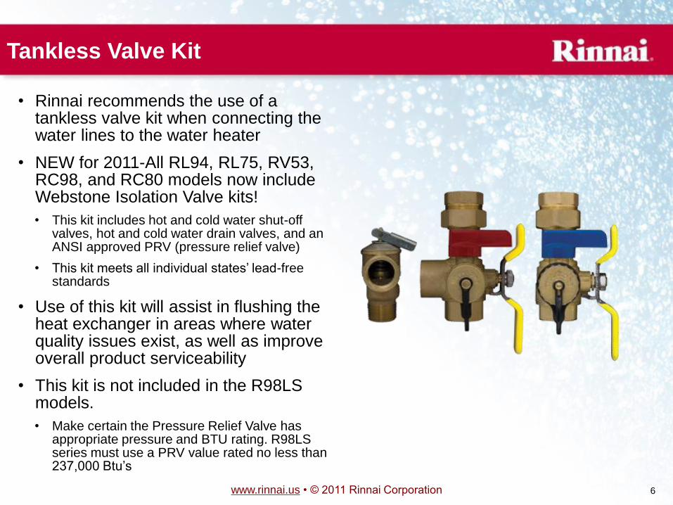
Tankless Valve Kit
• Rinnai recommends the use of a tankless valve kit when connecting the water lines to the water heater
• NEW for 2011-All RL94, RL75, RV53, RC98, and RC80 models now include Webstone Isolation Valve kits!
• This kit includes hot and cold water shut-off valves, hot and cold water drain valves, and an ANSI approved PRV (pressure relief valve)
• This kit meets all individual states’ lead-free standards
• Use of this kit will assist in flushing the heat exchanger in areas where water quality issues exist, as well as improve overall product serviceability
• This kit is not included in the R98LS models.
• Make certain the Pressure Relief Valve has appropriate pressure and BTU rating. R98LS series must use a PRV value rated no less than 237,000 Btu’s
www.rinnai.us • © 2011 Rinnai Corporation 7
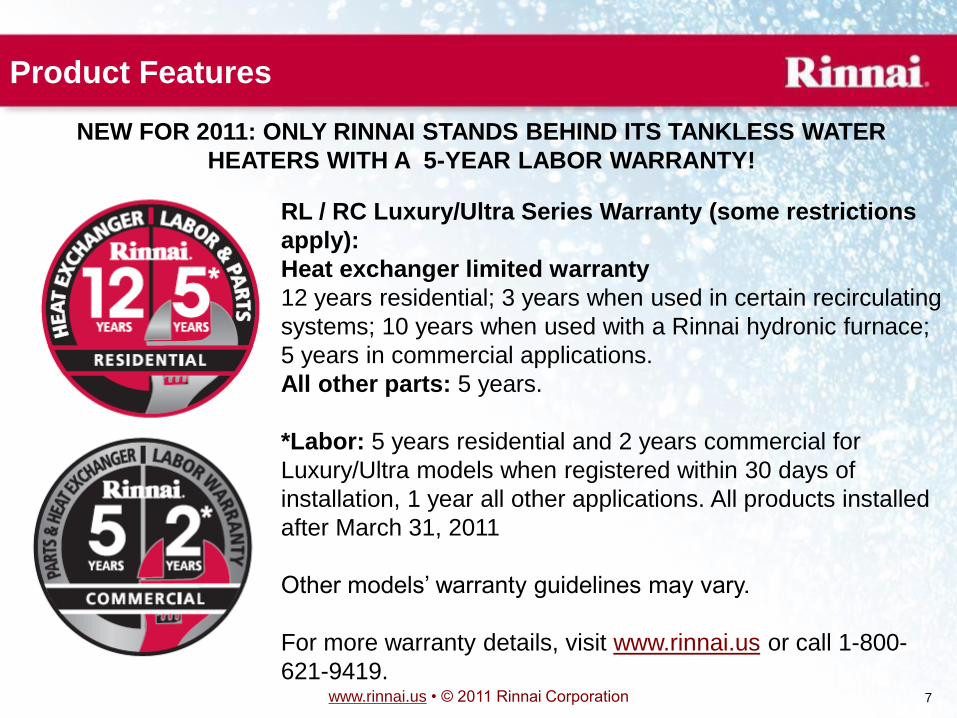
Product Features
NEW FOR 2011: ONLY RINNAI STANDS BEHIND ITS TANKLESS WATER
HEATERS WITH A 5-YEAR LABOR WARRANTY!
RL / RC Luxury/Ultra Series Warranty (some restrictions
apply):
Heat exchanger limited warranty
12 years residential; 3 years when used in certain recirculating
systems; 10 years when used with a Rinnai hydronic furnace;
5 years in commercial applications.
All other parts: 5 years.
*Labor: 5 years residential and 2 years commercial for
Luxury/Ultra models when registered within 30 days of
installation, 1 year all other applications. All products installed
after March 31, 2011
Other models’ warranty guidelines may vary.
For more warranty details, visit www.rinnai.us or call 1-800-
621-9419.
www.rinnai.us • © 2011 Rinnai Corporation 8
Product Features
• Rinnai tankless water heaters have an industry leading activation rate of 0.4 gpm* and lower
minimum gas input rate of 10,000 Btu
• This allows ignition for smaller amounts of water at higher incoming temperatures
• Water flow deactivation is less than 0.26 gpm* (also the best in the industry)
• Exceptions: (R)V53 and R98LS models
• Current non-condensing models are approved for mobile homes installations (Exception: R98LS)
• Whole house continuous hot water system when properly sized
• Non-condensing models have EF ratings of .82-.84
• Condensing models have EF ratings of .93 - .96
• Temperature controller for setting desired water temperatures
• Output temperature can be adjusted to provide specific water temperatures for home, schools, nursing homes, hotels, etc.
• Space saving, compact size
• Very low noise (49 decibels)
• All parts are replaceable
• †Life expectancy up to 15 – 20 years †Actual performance life will vary depending on water quality, usage rates, environmental conditions, and required maintenance scheduling. Refer to the
maintenance section of the operators manual for further details.
*Model Dependent
www.rinnai.us • © 2011 Rinnai Corporation 9
Safety Devices
• Maintenance / diagnostic codes are displayed on the temperature controller, simplifying service calls
• Safe, low voltage temperature controllers
• Flame rod indicator(s) (validates and / or indicates flame failure)
• Over heat bi-metal sensor(s)
• Integrated boiling protection
• Heat exchanger thermal fuses
• Built-in freeze protection to -22º F for indoor units and -4º F for outdoor units (must have gas and electricity)
• A drain down kit can be obtained to protect the unit from freezing in case of electrical failure or inadequate gas supply—non-condensing models only
• Combustion fan senses blocked intake or exhaust flue
• Indoor models also have a burner sensor to aid in monitoring proper air/fuel intake (model dependent)
• Direct electronic ignition (no standing pilot)
• Surge protector built in-line with the power supply
• Power supply is protected by a glass fuse (size will vary by model)
www.rinnai.us • © 2011 Rinnai Corporation 10
TANKLESS
WATER HEATER
SIZING
AND SEQUENCE
OF OPERATION
www.rinnai.us • © 2011 Rinnai Corporation 11
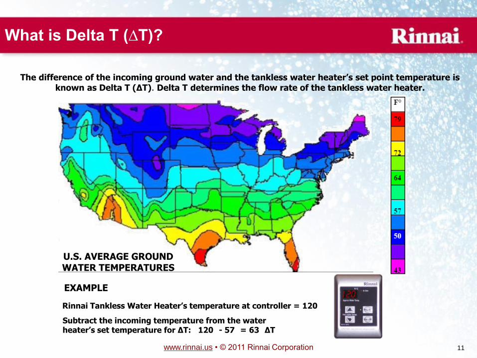
What is Delta T (∆T)?
The difference of the incoming ground water and the tankless water heater’s set point temperature is known as Delta T (∆T). Delta T determines the flow rate of the tankless water heater.
U.S. AVERAGE GROUND WATER TEMPERATURES
EXAMPLE
Rinnai Tankless Water Heater’s temperature at controller = 120
Subtract the incoming temperature from the water heater’s set temperature for ∆T: 120
- 57
= 63
∆T
www.rinnai.us • © 2011 Rinnai Corporation 12
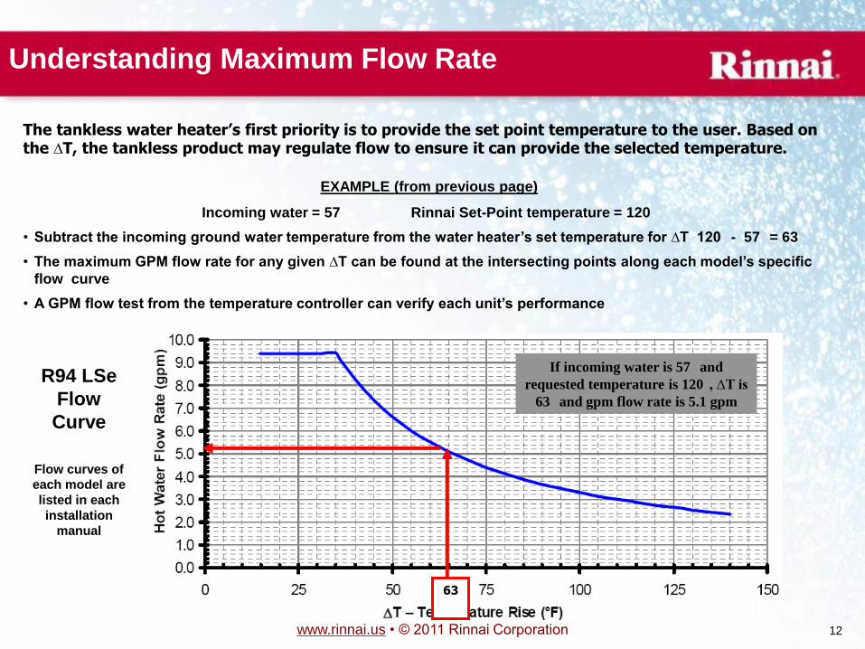
Understanding Maximum Flow Rate
EXAMPLE (from previous page)
Incoming water = 57
Rinnai Set-Point temperature = 120
• Subtract the incoming ground water temperature from the water heater’s set temperature for ∆T 120
- 57
= 63
• The maximum GPM flow rate for any given ∆T can be found at the intersecting points along each model’s specific
flow curve
• A GPM flow test from the temperature controller can verify each unit’s performance
R94 LSe
Flow
Curve
Flow curves of
each model are
listed in each
installation
manual
The tankless water heater’s first priority is to provide the set point temperature to the user. Based on the ∆T, the tankless product may regulate flow to ensure it can provide the selected temperature.
63
If incoming water is 57
and
requested temperature is 120
, ∆T is
63
and gpm flow rate is 5.1 gpm
www.rinnai.us • © 2011 Rinnai Corporation 13
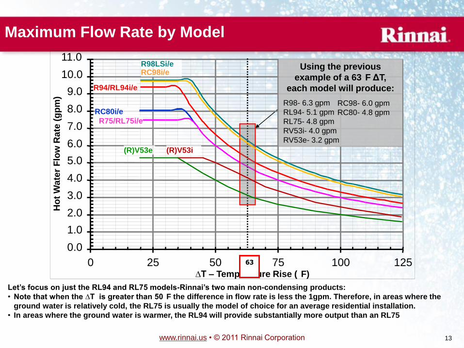
Maximum Flow Rate by Model
0.0
1.0
2.0
3.0
4.0
5.0
6.0
7.0
8.0
9.0
10.0
11.0
0 25 50 75 100 125 ∆T – Temperature Rise (
F)
Ho
t W
ate
r F
low
Ra
te (
gp
m)
R98LSi/e RC98i/e
R94/RL94i/e
R75/RL75i/e
63
Using the previous
example of a 63
F ΔT,
each model will produce:
R98- 6.3 gpm
RL94- 5.1 gpm
RL75- 4.8 gpm
RV53i- 4.0 gpm
RV53e- 3.2 gpm
(R)V53i (R)V53e
Let’s focus on just the RL94 and RL75 models-Rinnai’s two main non-condensing products:
• Note that when the ∆T is greater than 50
F the difference in flow rate is less the 1gpm. Therefore, in areas where the
ground water is relatively cold, the RL75 is usually the model of choice for an average residential installation.
• In areas where the ground water is warmer, the RL94 will provide substantially more output than an RL75
RC80i/e RC98- 6.0 gpm
RC80- 4.8 gpm
www.rinnai.us • © 2011 Rinnai Corporation 14
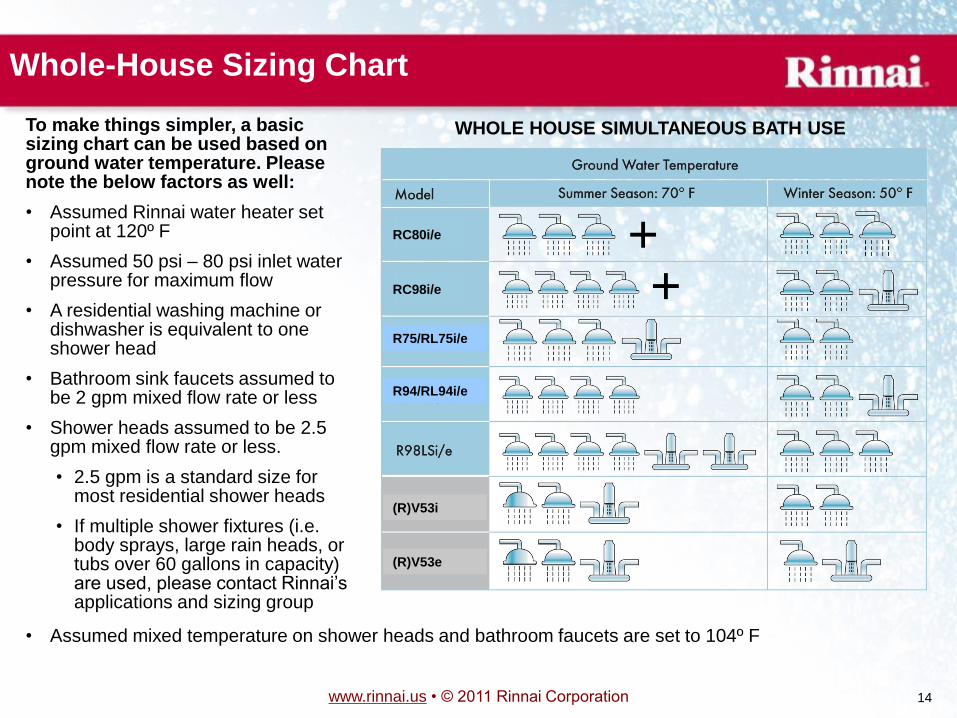
Whole-House Sizing Chart
• Assumed mixed temperature on shower heads and bathroom faucets are set to 104º F
WHOLE HOUSE SIMULTANEOUS BATH USE To make things simpler, a basic sizing chart can be used based on ground water temperature. Please note the below factors as well:
• Assumed Rinnai water heater set point at 120º F
• Assumed 50 psi – 80 psi inlet water pressure for maximum flow
• A residential washing machine or dishwasher is equivalent to one shower head
• Bathroom sink faucets assumed to be 2 gpm mixed flow rate or less
• Shower heads assumed to be 2.5 gpm mixed flow rate or less.
• 2.5 gpm is a standard size for most residential shower heads
• If multiple shower fixtures (i.e. body sprays, large rain heads, or tubs over 60 gallons in capacity) are used, please contact Rinnai’s applications and sizing group
RC80i/e
RC98i/e + +
R75/RL75i/e
R94/RL94i/e
(R)V53i
(R)V53e
www.rinnai.us • © 2011 Rinnai Corporation 15
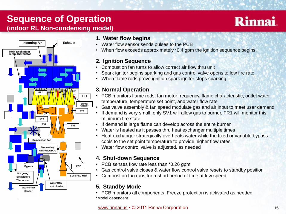
1. Water flow begins • Water flow sensor sends pulses to the PCB
• When flow exceeds approximately *0.4 gpm the ignition sequence begins.
2. Ignition Sequence • Combustion fan turns to allow correct air flow thru unit
• Spark igniter begins sparking and gas control valve opens to low fire rate
• When flame rods prove ignition spark igniter stops sparking
3. Normal Operation • PCB monitors flame rods, fan motor frequency, flame characteristic, outlet water
temperature, temperature set point, and water flow rate
• Gas valve assembly & fan speed modulate gas and air input to meet user demand
• If demand is very small, only SV1 will allow gas to burner, FR1 will monitor this
minimum fire state
• If demand is large flame can develop across the entire burner
• Water is heated as it passes thru heat exchanger multiple times
• Heat exchanger strategically overheats water while the fixed or variable bypass
cools to the set point temperature to provide higher flow rates
• Water flow control valve is adjusted, as needed
4. Shut-down Sequence • PCB senses flow rate less than *0.26 gpm
• Gas control valve closes & water flow control valve resets to standby position
• Combustion fan runs for a short period of time at low speed
5. Standby Mode • PCB monitors all components. Freeze protection is activated as needed *Model dependent
Water Flow
Sensor
PCB
Combustion Fan
FR 1
Igniter
SV4
SV1
SV0 or SV Main
Modulating
Gas Valve/POV
SV2
Water flow
control valve
Out going
Temperature
Thermistor
Incoming Air Exhaust
Heat Exchanger Temp.Thermistor
Bypass
Sequence of Operation (indoor RL Non-condensing model)
SV3
FR 2
Burner Sensor
www.rinnai.us • © 2011 Rinnai Corporation 17
Manufactured Home Installation
• Modular Homes
• A modular, panelized, or precut home is built at a factory and then transported to the site and assembled.
These types of construction fall under the regulation of the model building code enforced in the
jurisdiction where the home is to be located.
• All Rinnai water heaters are approved for installation in modular, panelized, or precut homes
• Manufactured Homes (or Mobile Homes)
• The ANSI standard defines a manufactured home as a structure, transportable in one or more sections,
which in the traveling mode, is eight body feet or more in width or forty body feet or more in length, or
when erected on site, is 320 or more square feet.
• Rinnai R75/RL75, R94/RL94, and V53i/RV53i models with ―VB‖ in the full model number are
approved by CSA for installation in manufactured or mobile homes
• Rinnai V53e/RV53e models manufactured in April, 2010 or later are also approved by CSA for
installation in manufactured or mobile homes
• At the time of this publication, all other Rinnai model water heaters are not approved for manufactured
or mobile home installation. Contact Rinnai if needed for a current list of approved models.
• Furthermore, the ANSI standard requires that all products for installation in manufactured homes be CSA
certified with required labeling and instructions as well the ability to field convert gas type as necessary.
• VB models meet these requirements
• Most models prior to the VB series were also gas type convertible, however only VB models are
approved to this standard for installation in manufactured homes.
• VB models are also approved to retrofit into existing manufactured homes (local and state codes may
apply)
www.rinnai.us • © 2011 Rinnai Corporation 18
Product Installation Key Points (All current Rinnai models)
• Rinnai’s tankless water heaters can be used in both residential and commercial applications
• Exception: (R)V53 models are not to be used in commercial applications
• Units are available as either natural or propane gas
• Indoor models must be installed within the confines of a structure. This includes carports and
crawlspaces. Outdoor models must be installed outside.
• Residential installations are potable water applications only in single family dwellings with a
maximum water temperature setting of 140ºF
• Commercial installations are potable water applications for restaurants, schools, hotels, car
washes, coin laundries, assisted living facilities, etc. Hydronic applications are also defined as
commercial installations.
• The MCC-91 commercial temperature controller (optional) allows a maximum water
temperature setting of 160º F on (R)V53 and R75/RL75 models
• The MCC-91 commercial temperature controller (optional) allows a maximum water
temperature setting of 185º F on the R94/RL94 and R98LS models
DO NOT use these units in any application involving chemically treated water, (i.e. chlorinated
pool water, hot tubs, etc,)
www.rinnai.us • © 2011 Rinnai Corporation 19
Installation Requirements (All current models)
It is very important to ensure the following incoming sources are within specification:
• Electricity –
• A properly polarized and grounded 120 VAC, 60 Hz supply is required. Temperature
controllers operate on 12 VDC only supplied by the water heater.
• Water –
• Pipe sizing and incoming water pressure must meet each model’s requirements as stated in the installation manual; and, water quality must meet the EPA’s National Secondary Drinking Standards
• Gas –
• Adequate gas pressure and volume (gas line sizing) must be verified for proper operation
• Venting (air) –
• Vent components that are certified and listed with the water heater model must be
installed to specifications and proper clearances must be maintained
• Code Adherence –
• All national, state, and local codes must be followed
www.rinnai.us • © 2011 Rinnai Corporation 20
VENTING
REQUIREMENTS • It is imperative to ensure proper vent guidelines are followed
• Ensure non-condensing and condensing guidelines are understood
• Do not mix vent parts or individual requirements between non-condensing and condensing models as dangerous
safety conditions could occur!
! WARNING
Improper installation of vent system and components, or failure to follow all installation
instructions, can result in property damage or serious injury
www.rinnai.us • © 2011 Rinnai Corporation 21
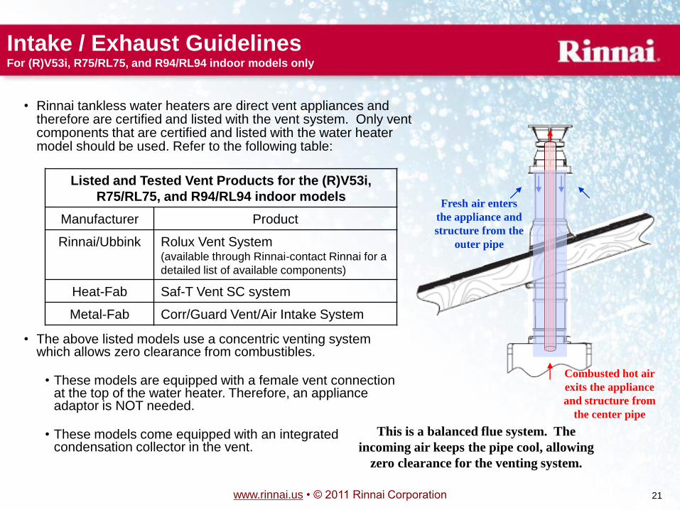
• The above listed models use a concentric venting system which allows zero clearance from combustibles.
• These models are equipped with a female vent connection at the top of the water heater. Therefore, an appliance adaptor is NOT needed.
• These models come equipped with an integrated condensation collector in the vent.
Combusted hot air
exits the appliance
and structure from
the center pipe
Fresh air enters
the appliance and
structure from the
outer pipe
This is a balanced flue system. The
incoming air keeps the pipe cool, allowing
zero clearance for the venting system.
• Rinnai tankless water heaters are direct vent appliances and therefore are certified and listed with the vent system. Only vent components that are certified and listed with the water heater model should be used. Refer to the following table:
Listed and Tested Vent Products for the (R)V53i,
R75/RL75, and R94/RL94 indoor models
Manufacturer Product
Rinnai/Ubbink Rolux Vent System (available through Rinnai-contact Rinnai for a
detailed list of available components)
Heat-Fab Saf-T Vent SC system
Metal-Fab Corr/Guard Vent/Air Intake System
Intake / Exhaust Guidelines For (R)V53i, R75/RL75, and R94/RL94 indoor models only
www.rinnai.us • © 2011 Rinnai Corporation 22
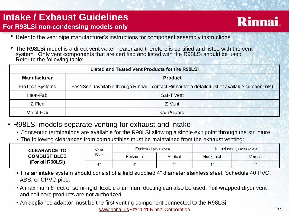
• R98LSi models separate venting for exhaust and intake • Concentric terminations are available for the R98LSi allowing a single exit point through the structure.
• The following clearances from combustibles must be maintained from the exhaust venting:
CLEARANCE TO
COMBUSTIBLES
(For all R98LSi)
Vent
Size
Enclosed (on 4 sides) Unenclosed (3 sides or less)
Horizontal Vertical Horizontal Vertical
4‖ 4‖ 4‖ 1‖ 1‖
• The air intake system should consist of a field supplied 4‖ diameter stainless steel, Schedule 40 PVC,
ABS, or CPVC pipe.
• A maximum 6 feet of semi-rigid flexible aluminum ducting can also be used. Foil wrapped dryer vent
and cell core products are not authorized.
• An appliance adaptor must be the first venting component connected to the R98LSi
Intake / Exhaust Guidelines For R98LSi non-condensing models only
• Refer to the vent pipe manufacturer’s instructions for component assembly instructions.
• The R98LSi model is a direct vent water heater and therefore is certified and listed with the vent system. Only vent components that are certified and listed with the R98LSi should be used. Refer to the following table:
Listed and Tested Vent Products for the R98LSi
Manufacturer Product
ProTech Systems FasNSeal (available through Rinnai—contact Rinnai for a detailed list of available components)
Heat-Fab Saf-T Vent
Z-Flex Z-Vent
Metal-Fab Corr/Guard
www.rinnai.us • © 2011 Rinnai Corporation 23
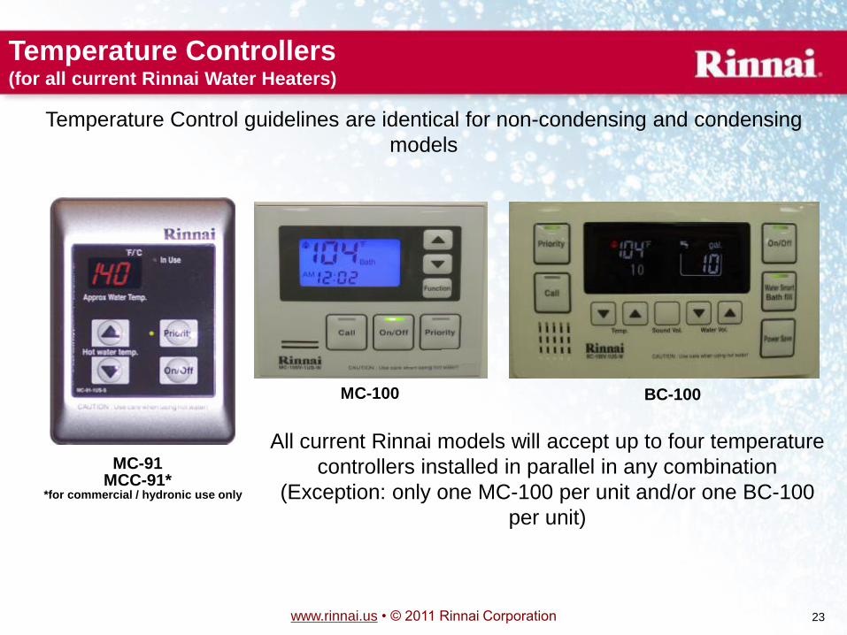
Temperature Controllers (for all current Rinnai Water Heaters)
MC-91 MCC-91*
MC-100 BC-100
*for commercial / hydronic use only
All current Rinnai models will accept up to four temperature
controllers installed in parallel in any combination
(Exception: only one MC-100 per unit and/or one BC-100
per unit)
Temperature Control guidelines are identical for non-condensing and condensing
models
www.rinnai.us • © 2011 Rinnai Corporation 24
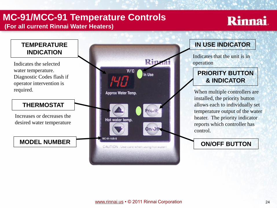
When multiple controllers are
installed, the priority button
allows each to individually set
temperature output of the water
heater. The priority indicator
reports which controller has
control.
Indicates the selected
water temperature.
Diagnostic Codes flash if
operator intervention is
required.
ON/OFF BUTTON MODEL NUMBER
IN USE INDICATOR
Indicates that the unit is in
operation
TEMPERATURE
INDICATION
THERMOSTAT
Increases or decreases the
desired water temperature
PRIORITY BUTTON
& INDICATOR
MC-91/MCC-91 Temperature Controls (For all current Rinnai Water Heaters)
www.rinnai.us • © 2011 Rinnai Corporation 25
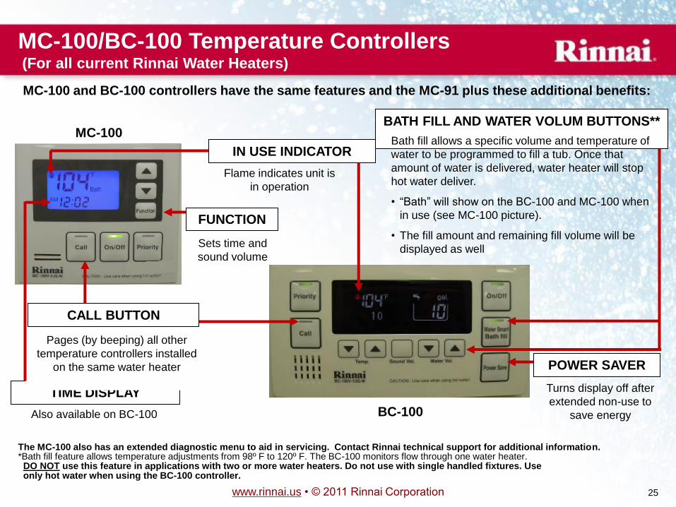
MC-100/BC-100 Temperature Controllers (For all current Rinnai Water Heaters)
IN USE INDICATOR
Flame indicates unit is
in operation
TIME DISPLAY
CALL BUTTON
Pages (by beeping) all other
temperature controllers installed
on the same water heater
Sets time and
sound volume
FUNCTION
POWER SAVER
Turns display off after
extended non-use to
save energy
BATH FILL AND WATER VOLUM BUTTONS**
Bath fill allows a specific volume and temperature of
water to be programmed to fill a tub. Once that
amount of water is delivered, water heater will stop
hot water deliver.
• ―Bath‖ will show on the BC-100 and MC-100 when
in use (see MC-100 picture).
• The fill amount and remaining fill volume will be
displayed as well
The MC-100 also has an extended diagnostic menu to aid in servicing. Contact Rinnai technical support for additional information. *Bath fill feature allows temperature adjustments from 98º F to 120º F. The BC-100 monitors flow through one water heater. DO NOT use this feature in applications with two or more water heaters. Do not use with single handled fixtures. Use only hot water when using the BC-100 controller.
Also available on BC-100
MC-100
BC-100
MC-100 and BC-100 controllers have the same features and the MC-91 plus these additional benefits:
www.rinnai.us • © 2011 Rinnai Corporation 26
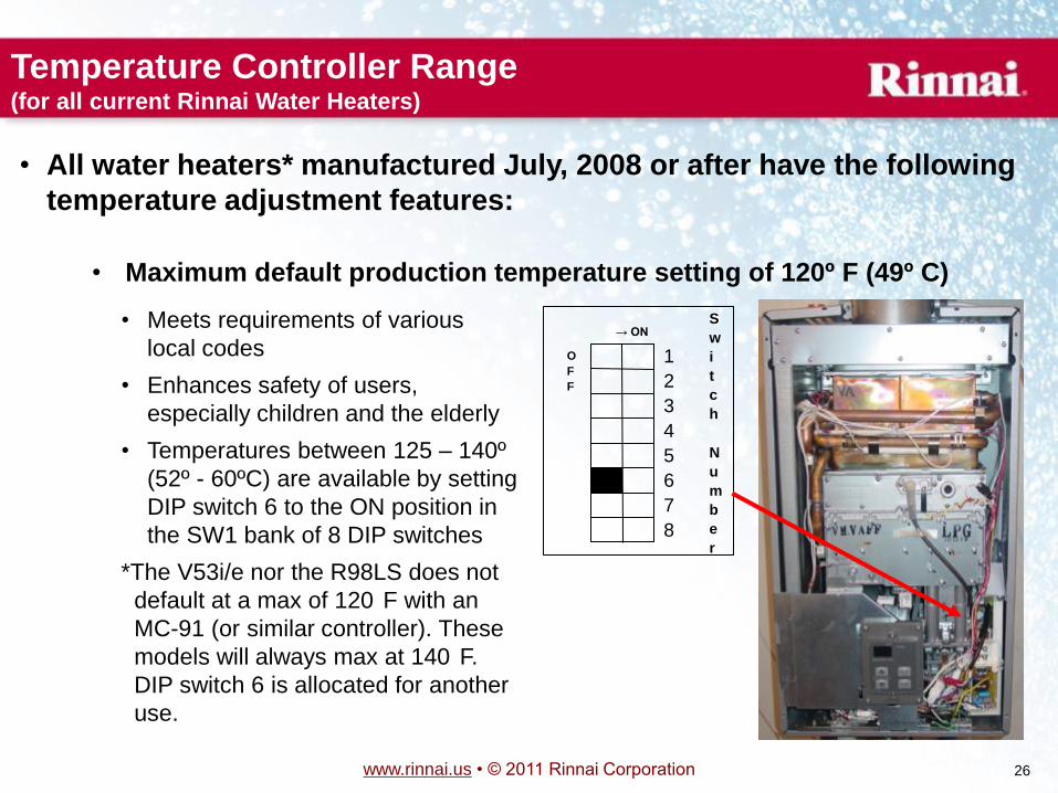
• All water heaters* manufactured July, 2008 or after have the following
temperature adjustment features:
• Maximum default production temperature setting of 120º F (49º C)
Temperature Controller Range (for all current Rinnai Water Heaters)
S
w
i
t
c
h
N
u
m
b
e
r
→ ON
O
F
F
1
2
3
4
5
6
7
8
• Meets requirements of various
local codes
• Enhances safety of users,
especially children and the elderly
• Temperatures between 125 – 140º
(52º - 60ºC) are available by setting
DIP switch 6 to the ON position in
the SW1 bank of 8 DIP switches
*The V53i/e nor the R98LS does not
default at a max of 120
F with an
MC-91 (or similar controller). These
models will always max at 140
F.
DIP switch 6 is allocated for another
use.
www.rinnai.us • © 2011 Rinnai Corporation 27
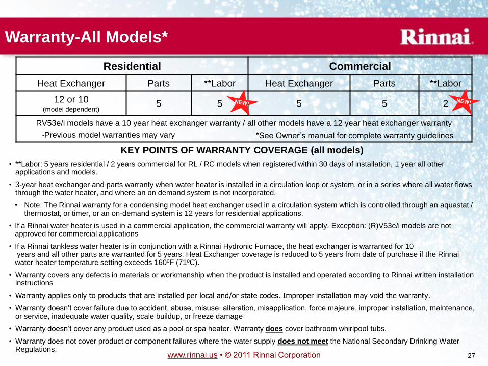
KEY POINTS OF WARRANTY COVERAGE (all models)
• **Labor: 5 years residential / 2 years commercial for RL / RC models when registered within 30 days of installation, 1 year all other applications and models.
• 3-year heat exchanger and parts warranty when water heater is installed in a circulation loop or system, or in a series where all water flows through the water heater, and where an on demand system is not incorporated.
• Note: The Rinnai warranty for a condensing model heat exchanger used in a circulation system which is controlled through an aquastat / thermostat, or timer, or an on-demand system is 12 years for residential applications.
• If a Rinnai water heater is used in a commercial application, the commercial warranty will apply. Exception: (R)V53e/i models are not approved for commercial applications
• If a Rinnai tankless water heater is in conjunction with a Rinnai Hydronic Furnace, the heat exchanger is warranted for 10 years and all other parts are warranted for 5 years. Heat Exchanger coverage is reduced to 5 years from date of purchase if the Rinnai water heater temperature setting exceeds 160ºF (71ºC).
• Warranty covers any defects in materials or workmanship when the product is installed and operated according to Rinnai written installation instructions
• Warranty applies only to products that are installed per local and/or state codes. Improper installation may void the warranty.
• Warranty doesn’t cover failure due to accident, abuse, misuse, alteration, misapplication, force majeure, improper installation, maintenance, or service, inadequate water quality, scale buildup, or freeze damage
• Warranty doesn’t cover any product used as a pool or spa heater. Warranty does cover bathroom whirlpool tubs.
• Warranty does not cover product or component failures where the water supply does not meet the National Secondary Drinking Water Regulations.
Warranty-All Models*
Residential Commercial
Heat Exchanger Parts **Labor Heat Exchanger Parts **Labor
12 or 10 (model dependent)
5 5 5 5 2
RV53e/i models have a 10 year heat exchanger warranty / all other models have a 12 year heat exchanger warranty
•Previous model warranties may vary *See Owner’s manual for complete warranty guidelines
www.rinnai.us • © 2011 Rinnai Corporation 28
Rinnai Condensing
Water Heater
Installation Differences
The following highlights the differences of condensing
models as compared to non-condensing models.
Please read each model’s installation manual that comes with each product
Failure to comply with each model’s accompanying guidelines could void the warranty
www.rinnai.us • © 2011 Rinnai Corporation 29
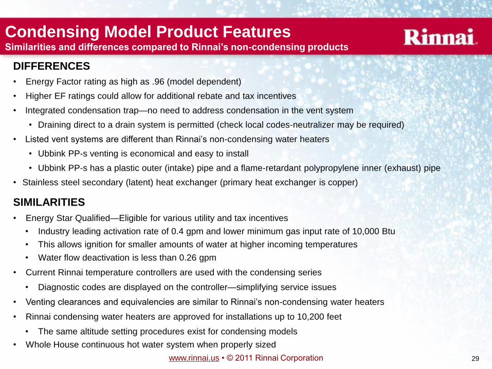
DIFFERENCES
• Energy Factor rating as high as .96 (model dependent)
• Higher EF ratings could allow for additional rebate and tax incentives
• Integrated condensation trap—no need to address condensation in the vent system
• Draining direct to a drain system is permitted (check local codes-neutralizer may be required)
• Listed vent systems are different than Rinnai’s non-condensing water heaters
• Ubbink PP-s venting is economical and easy to install
• Ubbink PP-s has a plastic outer (intake) pipe and a flame-retardant polypropylene inner (exhaust) pipe
• Stainless steel secondary (latent) heat exchanger (primary heat exchanger is copper)
Condensing Model Product Features Similarities and differences compared to Rinnai’s non-condensing products
SIMILARITIES
• Energy Star Qualified—Eligible for various utility and tax incentives
• Industry leading activation rate of 0.4 gpm and lower minimum gas input rate of 10,000 Btu
• This allows ignition for smaller amounts of water at higher incoming temperatures
• Water flow deactivation is less than 0.26 gpm
• Current Rinnai temperature controllers are used with the condensing series
• Diagnostic codes are displayed on the controller—simplifying service issues
• Venting clearances and equivalencies are similar to Rinnai’s non-condensing water heaters
• Rinnai condensing water heaters are approved for installations up to 10,200 feet
• The same altitude setting procedures exist for condensing models
• Whole House continuous hot water system when properly sized
www.rinnai.us • © 2011 Rinnai Corporation 30
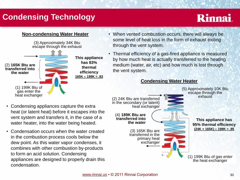
Condensing Technology
• When vented combustion occurs, there will always be
some level of heat loss in the form of exhaust exiting
through the vent system.
• Thermal efficiency of a gas-fired appliance is measured
by how much heat is actually transferred to the heating
medium (water, air, etc) and how much is lost through
the vent system.
(2) 165K Btu are transferred into
the water
(3) Approximately 34K Btu escape through the exhaust
This appliance
has 83%
thermal
efficiency 165K 199K = .83
• Condensing appliances capture the extra
heat (or latent heat) before it escapes into the
vent system and transfers it, in the case of a
water heater, into the water being heated.
• Condensation occurs when the water created
in the combustion process cools below the
dew point. As this water vapor condenses, it
combines with other combustion by-products
to form an acid solution. Condensing
appliances are designed to properly drain this
condensation.
(3) 165K Btu are transferred in the
primary heat exchanger
(1) 199K Btu of gas enter the heat exchanger
(4) 189K Btu are transferred into
the water
(2) 24K Btu are transferred in the secondary (or latent)
heat exchanger
(5) Approximately 10K Btu escape through the
exhaust
This appliance has
95% thermal efficiency
(24K + 165K) 199K = .95
(1) 199K Btu of gas enter the
heat exchanger
Non-condensing Water Heater
Condensing Water Heater
www.rinnai.us • © 2011 Rinnai Corporation 31
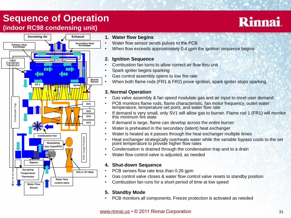
1. Water flow begins • Water flow sensor sends pulses to the PCB
• When flow exceeds approximately 0.4 gpm the ignition sequence begins
2. Ignition Sequence
• Combustion fan turns to allow correct air flow thru unit
• Spark igniter begins sparking
• Gas control assembly opens to low fire rate
• When both flame rods (FR1 & FR2) prove ignition, spark igniter stops sparking
3. Normal Operation
• Gas valve assembly & fan speed modulate gas and air input to meet user demand
• PCB monitors flame rods, flame characteristic, fan motor frequency, outlet water temperature, temperature set point, and water flow rate
• If demand is very small, only SV1 will allow gas to burner. Flame rod 1 (FR1) will monitor this minimum fire state
• If demand is large, flame can develop across the entire burner
• Water is preheated in the secondary (latent) heat exchanger
• Water is heated as it passes through the heat exchanger multiple times
• Heat exchanger strategically overheats water while the variable bypass cools to the set point temperature to provide higher flow rates
• Condensation is drained through the condensation trap and to a drain
• Water flow control valve is adjusted, as needed
4. Shut-down Sequence • PCB senses flow rate less than 0.26 gpm
• Gas control valve closes & water flow control valve resets to standby position
• Combustion fan runs for a short period of time at low speed
5. Standby Mode • PCB monitors all components. Freeze protection is activated as needed
PC
B /
Su
rge
Pro
tecto
r
Water Flow
Sensor
Combustion Fan
SV3
SV4
SV0 or SV Main
Modulating
Gas Valve/POV
SV2
Water flow
control valve
Out going
Temperature
Thermistor
Incoming Air Exhaust
Bypass
Igniter FR 1
FR 2
SV1
Con
de
nsa
te T
rap
Secondary Heat Exchanger Primary Heat
Exchanger
Heat Exchanger Thermistor
Burner Sensor
Sequence of Operation (indoor RC98 condensing unit)
www.rinnai.us • © 2011 Rinnai Corporation 32
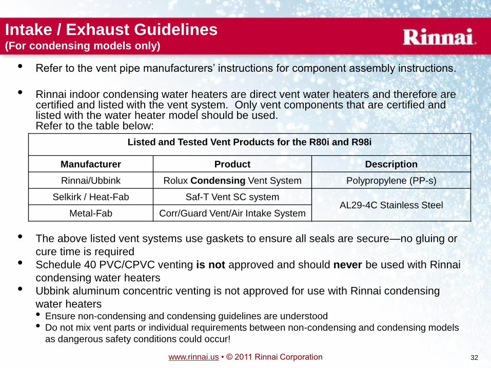
Intake / Exhaust Guidelines (For condensing models only)
• Refer to the vent pipe manufacturers’ instructions for component assembly instructions.
• Rinnai indoor condensing water heaters are direct vent water heaters and therefore are certified and listed with the vent system. Only vent components that are certified and listed with the water heater model should be used. Refer to the table below:
Listed and Tested Vent Products for the R80i and R98i
Manufacturer Product Description
Rinnai/Ubbink Rolux Condensing Vent System Polypropylene (PP-s)
Selkirk / Heat-Fab Saf-T Vent SC system AL29-4C Stainless Steel
Metal-Fab Corr/Guard Vent/Air Intake System
• The above listed vent systems use gaskets to ensure all seals are secure—no gluing or
cure time is required
• Schedule 40 PVC/CPVC venting is not approved and should never be used with Rinnai
condensing water heaters
• Ubbink aluminum concentric venting is not approved for use with Rinnai condensing
water heaters • Ensure non-condensing and condensing guidelines are understood
• Do not mix vent parts or individual requirements between non-condensing and condensing models
as dangerous safety conditions could occur!
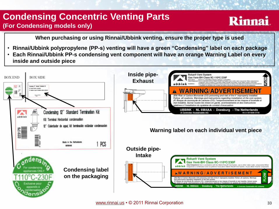
www.rinnai.us • © 2011 Rinnai Corporation 33
Condensing label
on the packaging
Warning label on each individual vent piece
Condensing Concentric Venting Parts (For Condensing models only)
When purchasing or using Rinnai/Ubbink venting, ensure the proper type is used
• Rinnai/Ubbink polypropylene (PP-s) venting will have a green ―Condensing‖ label on each package
• Each Rinnai/Ubbink PP-s condensing vent component will have an orange Warning Label on every
inside and outside piece
Inside pipe-
Exhaust
Outside pipe-
Intake
www.rinnai.us • © 2011 Rinnai Corporation 34
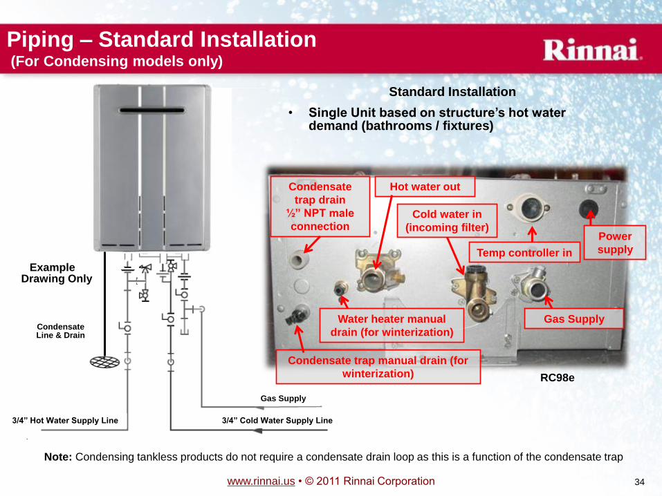
Piping – Standard Installation (For Condensing models only)
Gas Supply
3/4‖ Hot Water Supply Line 3/4‖ Cold Water Supply Line
Example Drawing Only
Standard Installation
• Single Unit based on structure’s hot water demand (bathrooms / fixtures)
Condensate Line & Drain
Condensate
trap drain
½‖ NPT male
connection
Hot water out
Cold water in
(incoming filter)
Gas Supply
Temp controller in
Power
supply
Condensate trap manual drain (for
winterization)
Water heater manual
drain (for winterization)
RC98e
Note: Condensing tankless products do not require a condensate drain loop as this is a function of the condensate trap
www.rinnai.us • © 2011 Rinnai Corporation 35
Rinnai Condensing Water Heater FAQ
1. Can the condensing product be used for hydronic heating?
• Condensing products are certified and tested to ANSI Z21.10.3/CSA 4.3. This is the same
standard as our non-condensing product. Therefore, only open-loop hydronic applications
are permitted (check local codes too). Contact Rinnai Engineering for more details (1-800-
621-9419)
2. Is a neutralizer or neutralizing agent required for the condensation?
• This will depend on local code. Third-party neutralizers are readily available at Rinnai
distributors and supply houses.
3. Is the integrated condensation trap freeze protected
• Yes, there are heating elements on this trap (power must be applied). There is also a drain
plug for quick and easy draining (for winter storage).
4. Does the condensation trap require priming?
• No, in most cases normal operation will self-prime the trap (approximately 9-11 minutes)
5. What is the temperature of the exhaust? • Exhaust gases are approximately 120
F-135
F depending on incoming water temperature, demand, etc
6. What is the maximum temperature limit of Ubbink PP-s? • Ubbink PP-s has a maximum temperature in excess of 230
F. This is superior to PVC’s max limit of only
156
F.
www.rinnai.us • © 2011 Rinnai Corporation 36
7. What are the input parameters to ensure the condensing tankless water heater is truly
condensing (high efficiency operation)? • Under most circumstances this product will be operating in a condensing state. However, the exhaust will
not condense as easily and efficiency will decrease as incoming temperatures surpass 100
F.
• If the unit has heavy scale build-up in the heat exchanger, the unit may not condense—ensure proper
water quality is maintained
8. Is PVC or CPVC venting permitted? • No, PVC and CPVC require twice the amount of piping (for intake and exhaust), priming and gluing, and
long cure times (which sometimes aren’t followed—creating a potentially dangerous environment).
• If poor water quality exists and the heat exchanger begins to scale, flue gas temperatures could exceed
the maximum allowable temperatures of PVC/CPVC.
• Under most circumstances, Rinnai/Ubbink concentric PP-s condensing vent material will be more
economical and easier to install
9. Why do condensing tankless water heaters use a different type of Ubbink venting than
Rinnai’s non-condensing water heaters • Because of large amounts of condensation in the vent system (due to high efficiency), aluminum exhaust
piping—the type used for non-condensing products—could break down over time
• Because the exhaust gas temperatures on non-condensing products are much higher than the
condensing products, polypropylene (PP-s) venting—the type used for condensing products—could melt
10. What size and type of piping should be used to drain the condensation from the water
heater? • It is the responsibility of the plumbing contractor, engineer, installer, etc. to size water pipe. If in
question, please refer to local codes and common design practices.
Rinnai Condensing Water Heater FAQ
www.rinnai.us • © 2011 Rinnai Corporation 38
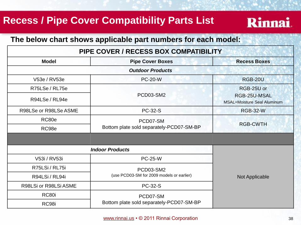
Recess / Pipe Cover Compatibility Parts List
PIPE COVER / RECESS BOX COMPATIBILITY
Model Pipe Cover Boxes Recess Boxes
Outdoor Products
V53e / RV53e PC-20-W RGB-20U
R75LSe / RL75e
PCD03-SM2
RGB-25U or
RGB-25U-MSAL
MSAL=Moisture Seal Aluminum R94LSe / RL94e
R98LSe or R98LSe ASME PC-32-S RGB-32-W
RC80e PCD07-SM
Bottom plate sold separately-PCD07-SM-BP RGB-CWTH
RC98e
Indoor Products
Not Applicable
V53i / RV53i PC-25-W
R75LSi / RL75i PCD03-SM2 (use PCD03-SM for 2009 models or earlier) R94LSi / RL94i
R98LSi or R98LSi ASME PC-32-S
RC80i PCD07-SM
Bottom plate sold separately-PCD07-SM-BP RC98i
The below chart shows applicable part numbers for each model:
www.rinnai.us • © 2011 Rinnai Corporation 39
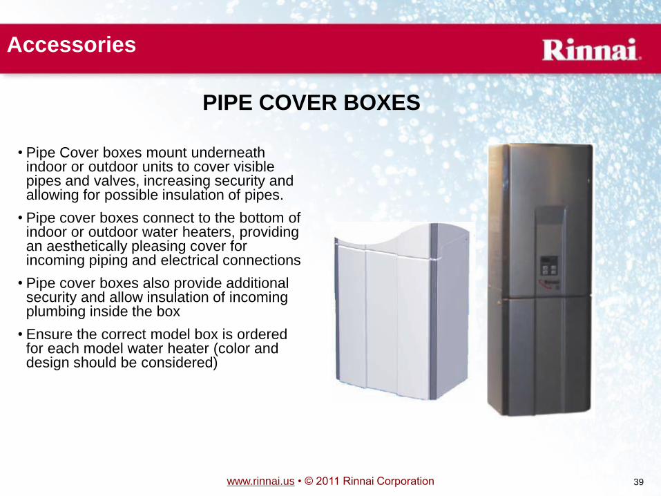
Accessories
PIPE COVER BOXES
• Pipe Cover boxes mount underneath indoor or outdoor units to cover visible pipes and valves, increasing security and allowing for possible insulation of pipes.
• Pipe cover boxes connect to the bottom of indoor or outdoor water heaters, providing an aesthetically pleasing cover for incoming piping and electrical connections
• Pipe cover boxes also provide additional security and allow insulation of incoming plumbing inside the box
• Ensure the correct model box is ordered for each model water heater (color and design should be considered)
www.rinnai.us • © 2011 Rinnai Corporation 40
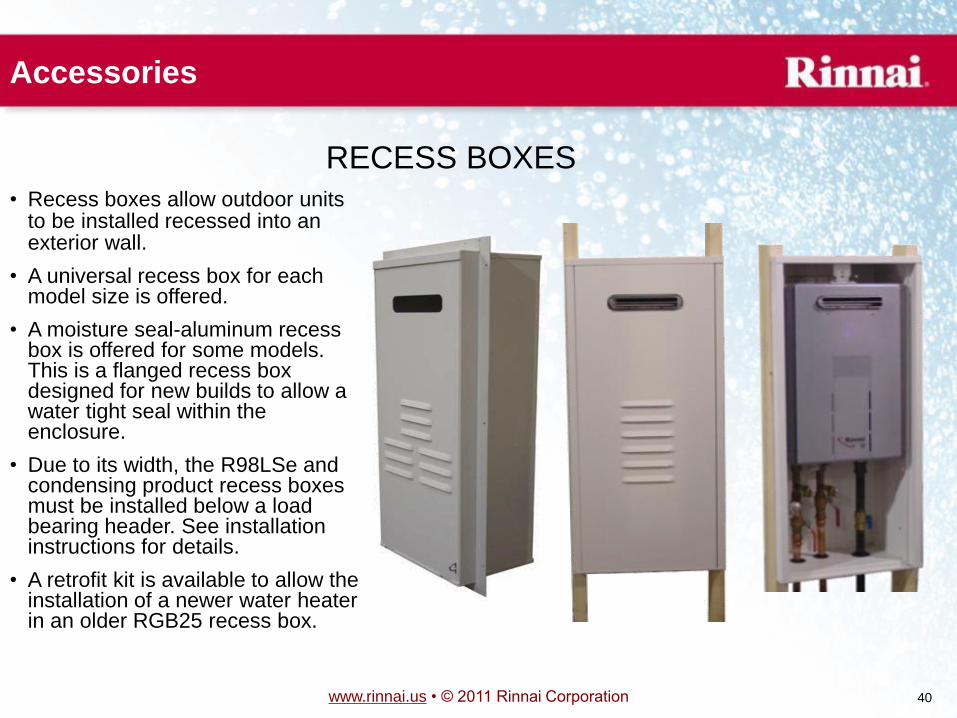
Accessories
RECESS BOXES
• Recess boxes allow outdoor units to be installed recessed into an exterior wall.
• A universal recess box for each model size is offered.
• A moisture seal-aluminum recess box is offered for some models. This is a flanged recess box designed for new builds to allow a water tight seal within the enclosure.
• Due to its width, the R98LSe and condensing product recess boxes must be installed below a load bearing header. See installation instructions for details.
• A retrofit kit is available to allow the installation of a newer water heater in an older RGB25 recess box.
www.rinnai.us • © 2011 Rinnai Corporation 41
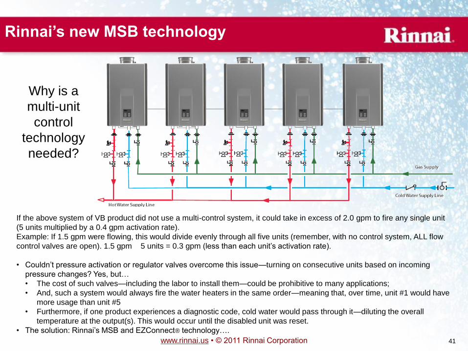
Why is a
multi-unit
control
technology
needed?
Rinnai’s new MSB technology
If the above system of VB product did not use a multi-control system, it could take in excess of 2.0 gpm to fire any single unit
(5 units multiplied by a 0.4 gpm activation rate).
Example: If 1.5 gpm were flowing, this would divide evenly through all five units (remember, with no control system, ALL flow
control valves are open). 1.5 gpm
5 units = 0.3 gpm (less than each unit’s activation rate).
• Couldn’t pressure activation or regulator valves overcome this issue—turning on consecutive units based on incoming
pressure changes? Yes, but…
• The cost of such valves—including the labor to install them—could be prohibitive to many applications;
• And, such a system would always fire the water heaters in the same order—meaning that, over time, unit #1 would have
more usage than unit #5
• Furthermore, if one product experiences a diagnostic code, cold water would pass through it—diluting the overall
temperature at the output(s). This would occur until the disabled unit was reset.
• The solution: Rinnai’s MSB and EZConnect® technology….
www.rinnai.us • © 2011 Rinnai Corporation 42
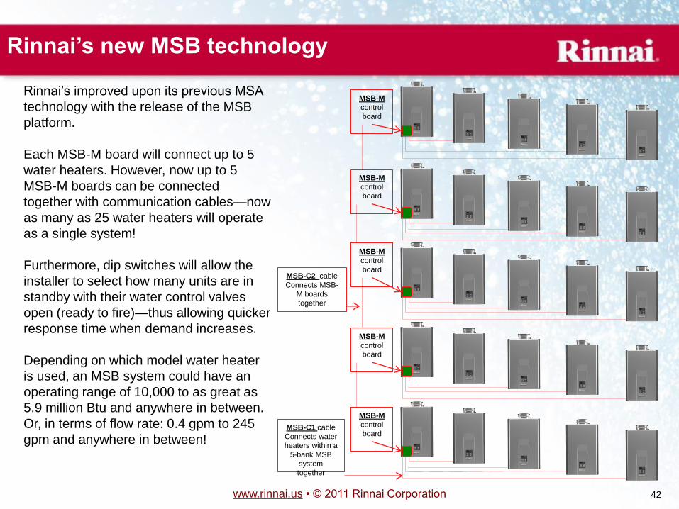
Rinnai’s improved upon its previous MSA
technology with the release of the MSB
platform.
Each MSB-M board will connect up to 5
water heaters. However, now up to 5
MSB-M boards can be connected
together with communication cables—now
as many as 25 water heaters will operate
as a single system!
Furthermore, dip switches will allow the
installer to select how many units are in
standby with their water control valves
open (ready to fire)—thus allowing quicker
response time when demand increases.
Depending on which model water heater
is used, an MSB system could have an
operating range of 10,000 to as great as
5.9 million Btu and anywhere in between.
Or, in terms of flow rate: 0.4 gpm to 245
gpm and anywhere in between!
Rinnai’s new MSB technology
MSB-M
control
board
MSB-M
control
board
MSB-M
control
board
MSB-M
control
board
MSB-M
control
board
MSB-C1 cable
Connects water
heaters within a
5-bank MSB
system
together
MSB-C2 cable
Connects MSB-
M boards
together
www.rinnai.us • © 2011 Rinnai Corporation 43
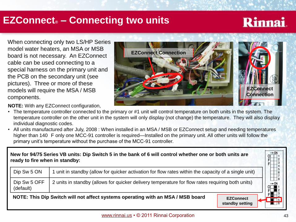
NOTE: With any EZConnect configuration,
• The temperature controller connected to the primary or #1 unit will control temperature on both units in the system. The
temperature controller on the other unit in the system will only display (not change) the temperature. They will also display
individual diagnostic codes.
• All units manufactured after July, 2008 : When installed in an MSA / MSB or EZConnect setup and needing temperatures
higher than 140
F only one MCC-91 controller is required—Installed on the primary unit. All other units will follow the
primary unit’s temperature without the purchase of the MCC-91 controller.
Dip Sw 5 ON 1 unit in standby (allow for quicker activation for flow rates within the capacity of a single unit)
Dip Sw 5 OFF
(default)
2 units in standby (allows for quicker delivery temperature for flow rates requiring both units)
New for 94/75 Series VB units: Dip Switch 5 in the bank of 6 will control whether one or both units are
ready to fire when in standby:
EZConnect
standby setting
NOTE: This Dip Switch will not affect systems operating with an MSA / MSB board
EZConnect® – Connecting two units
When connecting only two LS/HP Series
model water heaters, an MSA or MSB
board is not necessary. An EZConnect
cable can be used connecting to a
special harness on the primary unit and
the PCB on the secondary unit (see
pictures). Three or more of these
models will require the MSA / MSB
components.
EZConnect Connection
EZConnect
Connection
www.rinnai.us • © 2011 Rinnai Corporation 44
The End
Rinnai
Tankless Water Heater Training Program
Product Knowledge
Level I
WH Trng Prg Level I – Course #801101
040811