Embed Size (px)
Citation preview
This appliance shall be installed in accordance with:
• Manufacturer’s Installation Instructions
• Current AS/NZS 3000, AS/NZS 3500 & AS 5601
• Local Regulations and Municipal Building Codes
This appliance must be installed, serviced and removed by an Authorised Person.All Rinnai gas products
are A.G.A. certified.
Distributed and serviced in Australia under a Quality System certified as complying with ISO 9001 by SAI Global SAI Global
Demand Duo
Installation Manual
IMPORTANT NOTICE FOR INSTALLERS
Please leave these instructions with the end user after commissioning of the system and alert the end
user of the content in the sections “Warnings” and “Periodic Inspection” and “Maintenance”.
Rinnai Australia i Installation Manual
LOCATION .............................................................................................................................. 1
HORIZONTAL FLUE TERMINAL CLEARANCES................................................................... 2
Flueing for Internal Models ...................................................................................................... 3
Multiple Flue Terminals:........................................................................................................... 5
Installation:............................................................................................................................... 6
Assembly: ................................................................................................................................ 6
TYPICAL RINNAI DEMAND DUO INSTALLATION ................................................................ 7
Cold Water Supply:.................................................................................................................. 8
Hot Water Outlet ...................................................................................................................... 9
Return Pump............................................................................................................................ 9
Gas Supply .............................................................................................................................. 9
Filling Instructions .................................................................................................................... 9
Starting Instructions ................................................................................................................. 9
Demand Duo Principle of Operation ...................................................................................... 10
Demand Duo Preventative Maintenance ............................................................................... 10
Tank....................................................................................................................................... 10
Thermostat............................................................................................................................. 10
Primary Pump ........................................................................................................................ 10
Infinity Heat Source ............................................................................................................... 11
Infinity Fault Codes ................................................................................................................ 12
Ringmain Pump ..................................................................................................................... 12
Service:.................................................................................................................................. 12
CONTACT INFORMATION .................................................................................................. 14
TABLE OF CONTENTS
GENERAL INSTALLATION INSTRUCTIONS
These instructions apply to the Demand Duo range of water heaters:Models CoveredDD1 200 (external or internal) 250 or 315 (litre tank) N or L (Natural gas or LPG)DD1 250 (external) 250 or 315 (litre tank) N or L (Natural gas or LPG)DD2 200 (external or internal) 250 or 315 (litre tank) N or L (Natural gas or LPG)DD3 200 (external or internal) 250 or 315 (litre tank) N or L (Natural gas or LPG)DD4 200 (external or internal) 250 or 315 (litre tank) N or L (Natural gas or LPG)DD5 200 (external or internal) 250 or 315 (litre tank) N or L (Natural gas or LPG)DD6 200 (external or internal) 250 or 315 (litre tank) N or L (Natural gas or LPG)
Rinnai Demand Duo hot water systems must only be installed, commissioned, service and removedby an authorized person in accordance with these instructions, AS 5601, AS 3000 and AS 3500.4 andlocal regulations.
Rinnai Demand Duo hot water systems are not suitable or approved as a pool heater.
Read these instructions carefully before proceeding with the installation.
LOCATIONEnsure reasonable access for installation, servicing and removal. All valves, controls and pumps etcmust be easily accessible.
Rinnai Demand Duo tanks and any free stand frames must be mounted on a solid level base, capableof supporting the weight of the appliance when full of water. Ensure components are not allowed tostand in water. Spacers under the tank are recommended in wet areas.
All Demand Duo tanks are "left handed" with the water connections to the left when viewing thethermostat housing from the front.
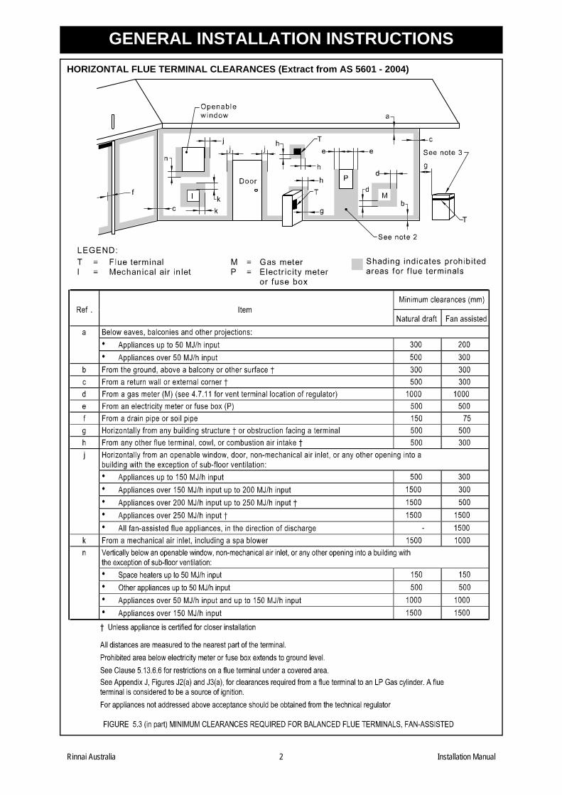
Gas booster flue terminals must be located in accordance with AS 5601 Fig 5.3 "Location of balancedflue terminals".
Rinnai Infinity and HD units are fan assisted appliances and thus have lower clearances than a naturaldraft appliance of the same MJ rating.
Rinnai Australia 1 Installation Manual
GENERAL INSTALLATION INSTRUCTIONS
HORIZONTAL FLUE TERMINAL CLEARANCES (Extract from AS 5601 - 2004)Rinnai Australia 2 Installation Manual
GENERAL INSTALLATION INSTRUCTIONS
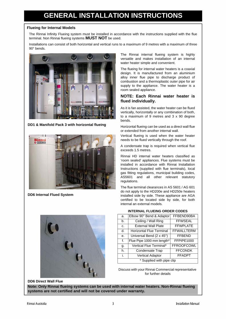
Flueing for Internal ModelsThe Rinnai Infinity Flueing system must be installed in accordance with the instructions supplied with the flueterminal. Non Rinnai flueing systems MUST NOT be used.
Installations can consist of both horizontal and vertical runs to a maximum of 9 metres with a maximum of three90° bends.
DD1 & Manifold Pack 3 with horizontal flueing
The Rinnai internal flueing system is highlyversatile and makes installation of an internalwater heater simple and convenient.
The flueing for internal water heaters is a coaxialdesign. It is manufactured from an aluminiumalloy inner flue pipe to discharge product ofcombustion and a thermoplastic outer pipe for airsupply to the appliance. The water heater is aroom sealed appliance.
NOTE: Each Rinnai water heater isflued individually.As it is fan assisted, the water heater can be fluedvertically, horizontally or any combination of both,to a maximum of 9 metres and 3 x 90 degreebends.
Horizontal flueing can be used as a direct wall flueor extended from another internal wall.
DD6 Internal Flued System
Vertical flueing is used when the water heaterneeds to be flued vertically through the roof.
A condensate trap is required when vertical flueexceeds 1.5 metres.
Rinnai HD internal water heaters classified as‘room sealed’ appliances. Flue systems must beinstalled in accordance with Rinnai InstallationInstructions (supplied with flue terminals), localgas fitting regulations, municipal building codes,AS5601 and all other relevant statutoryregulations.
The flue terminal clearances in AS 5601 / AG 601do not apply to the HD200e and HD250e heatersinstalled side by side. These appliance are AGAcertified to be located side by side, for bothinternal an external models.
INTERNAL FLUEING ORDER CODES
DD6 Direct Wall Flue
a. Elbow 90° Bend & Adaptor FFBEND90BAb. Ceiling / Wall Ring FFWSEALc. External Wall Plate FFWPLATEd. Horizontal Flue Terminal FFWALLTERMe. Universal Bend (2 x 45°) FFBENDf. Flue Pipe 1000 mm length* FFPIPE1000g. Vertical Flue Terminal* FFROOFCOWLh. Condensate Trap FFCONDKi. Vertical Adaptor FFADPT
* Supplied with pipe clip
Discuss with your Rinnai Commercial representative for further details
Note: Only Rinnai flueing systems can be used with internal water heaters. Non-Rinnai flueingsystems are not certified and will not be covered under warranty.
Rinnai Australia 3 Installation Manual
GENERAL INSTALLATION INSTRUCTIONS
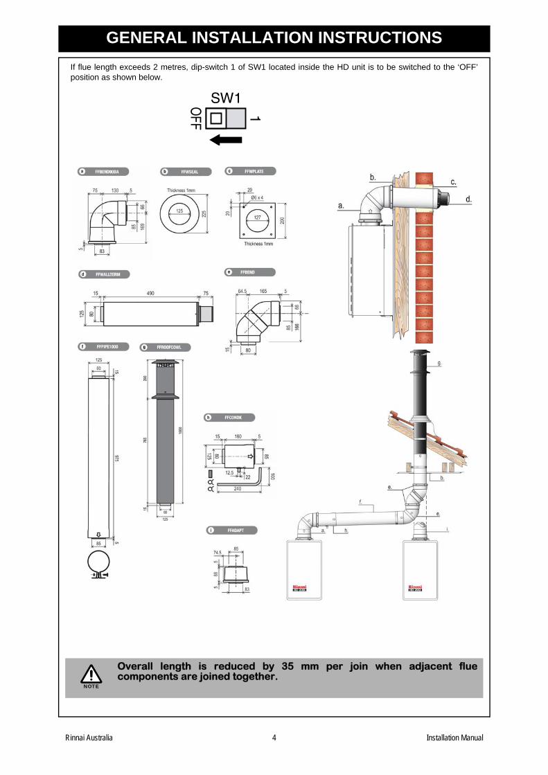
If flue length exceeds 2 metres, dip-switch 1 of SW1 located inside the HD unit is to be switched to the ‘OFF’position as shown below.Overall length is reduced by 35 mm per join when adjacent fluecomponents are joined together.
1OFF
SW1
NOTE
Rinnai Australia 4 Installation Manual
GENERAL INSTALLATION INSTRUCTIONS
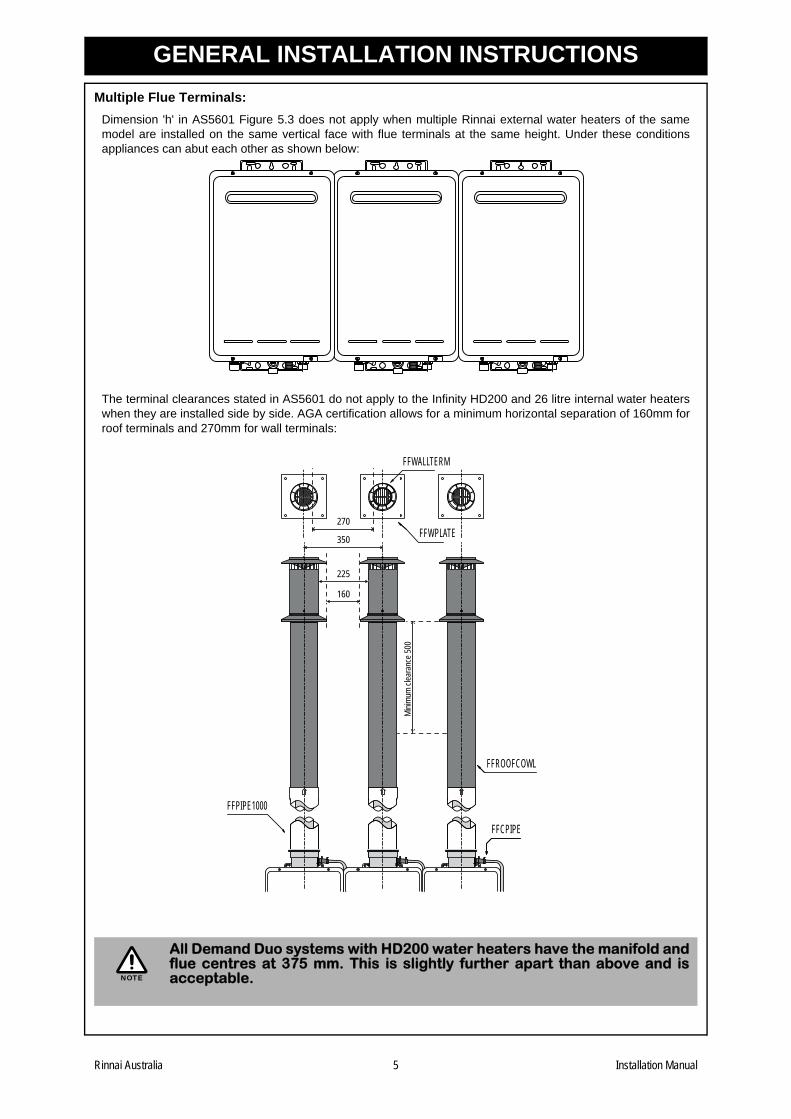
Multiple Flue Terminals:Dimension 'h' in AS5601 Figure 5.3 does not apply when multiple Rinnai external water heaters of the samemodel are installed on the same vertical face with flue terminals at the same height. Under these conditionsappliances can abut each other as shown below:
The terminal clearances stated in AS5601 do not apply to the Infinity HD200 and 26 litre internal water heaterswhen they are installed side by side. AGA certification allows for a minimum horizontal separation of 160mm forroof terminals and 270mm for wall terminals:
All Demand Duo systems with HD200 water heaters have the manifold andflue centres at 375 mm. This is slightly further apart than above and isacceptable.
UP U P U P
FFROOFCOWL
FFWPLATE350
160
225
270
Minim
um cl
eara
nce 5
00
FFWALLTERM
FFPIPE1000
FFCPIPE
NOTE
Rinnai Australia 5 Installation Manual
GENERAL INSTALLATION INSTRUCTIONS
Installation:Unpacking DD1Remove outer cardboard box. Remove screws attaching feet on tank to wooden pallet.
Carefully remove tank and attached gas booster from pallet and inspect for any transport damage. Ensure thatPTR valve, supplied in box is located and stored. Do not install if any components are damaged.
Unpacking DD2 +Tank:
Remove outer cardboard box. Remove screws attaching feet on tank to wooden pallet.
Carefully remove tank from pallet and inspect for any transport damage. Ensure that PTR valve, supplied in boxis located and stored. Do not install if any components are damaged.
HD water heaters:
With cardboard box in upright position, remove packing straps and slide lid upwards. Remove water heater frombase when required for installation.
Manifold:
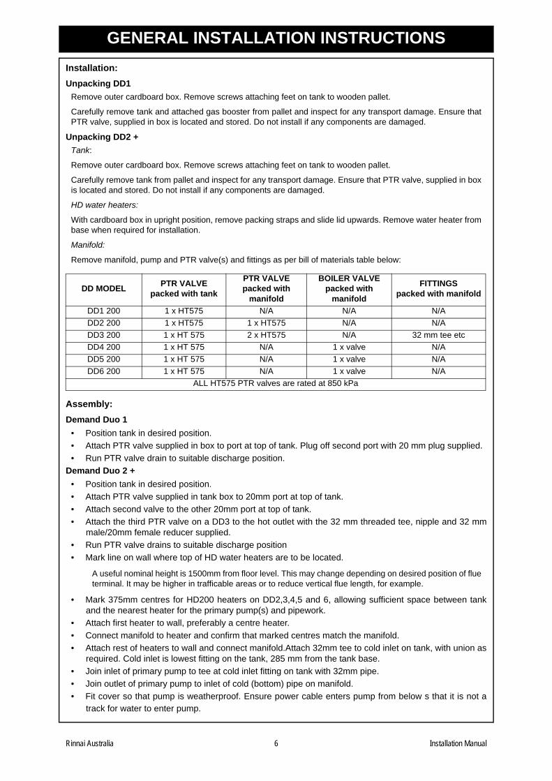
Remove manifold, pump and PTR valve(s) and fittings as per bill of materials table below:
Assembly:Demand Duo 1
• Position tank in desired position.• Attach PTR valve supplied in box to port at top of tank. Plug off second port with 20 mm plug supplied.• Run PTR valve drain to suitable discharge position.
Demand Duo 2 +• Position tank in desired position.• Attach PTR valve supplied in tank box to 20mm port at top of tank.• Attach second valve to the other 20mm port at top of tank.• Attach the third PTR valve on a DD3 to the hot outlet with the 32 mm threaded tee, nipple and 32 mm
male/20mm female reducer supplied.• Run PTR valve drains to suitable discharge position• Mark line on wall where top of HD water heaters are to be located.
A useful nominal height is 1500mm from floor level. This may change depending on desired position of flueterminal. It may be higher in trafficable areas or to reduce vertical flue length, for example.
• Mark 375mm centres for HD200 heaters on DD2,3,4,5 and 6, allowing sufficient space between tankand the nearest heater for the primary pump(s) and pipework.
• Attach first heater to wall, preferably a centre heater.• Connect manifold to heater and confirm that marked centres match the manifold.• Attach rest of heaters to wall and connect manifold.Attach 32mm tee to cold inlet on tank, with union as
required. Cold inlet is lowest fitting on the tank, 285 mm from the tank base.• Join inlet of primary pump to tee at cold inlet fitting on tank with 32mm pipe.• Join outlet of primary pump to inlet of cold (bottom) pipe on manifold.• Fit cover so that pump is weatherproof. Ensure power cable enters pump from below s that it is not a
track for water to enter pump.
DD MODEL PTR VALVEpacked with tank
PTR VALVEpacked with
manifold
BOILER VALVEpacked with
manifold
FITTINGSpacked with manifold
DD1 200 1 x HT575 N/A N/A N/ADD2 200 1 x HT575 1 x HT575 N/A N/ADD3 200 1 x HT 575 2 x HT575 N/A 32 mm tee etcDD4 200 1 x HT 575 N/A 1 x valve N/ADD5 200 1 x HT 575 N/A 1 x valve N/ADD6 200 1 x HT 575 N/A 1 x valve N/A
ALL HT575 PTR valves are rated at 850 kPa
Rinnai Australia 6 Installation Manual
GENERAL INSTALLATION INSTRUCTIONS
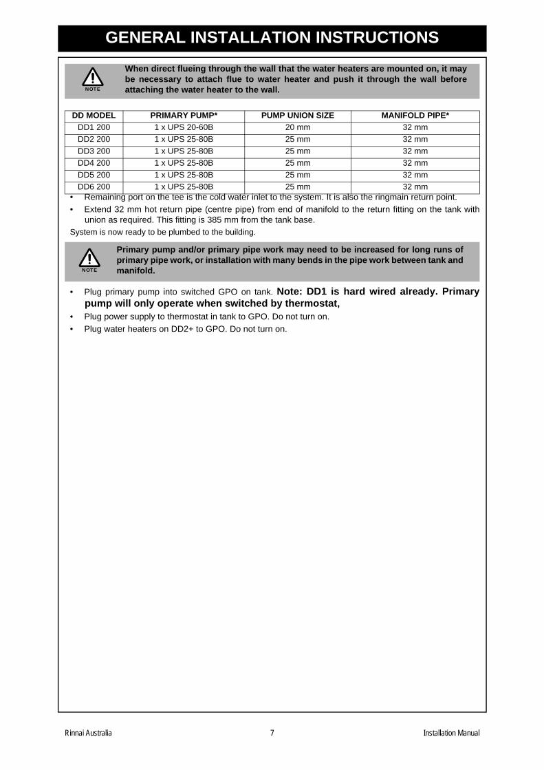
• Remaining port on the tee is the cold water inlet to the system. It is also the ringmain return point.• Extend 32 mm hot return pipe (centre pipe) from end of manifold to the return fitting on the tank with
union as required. This fitting is 385 mm from the tank base.System is now ready to be plumbed to the building.
• Plug primary pump into switched GPO on tank. Note: DD1 is hard wired already. Primarypump will only operate when switched by thermostat,
• Plug power supply to thermostat in tank to GPO. Do not turn on.• Plug water heaters on DD2+ to GPO. Do not turn on.
When direct flueing through the wall that the water heaters are mounted on, it maybe necessary to attach flue to water heater and push it through the wall beforeattaching the water heater to the wall.
DD MODEL PRIMARY PUMP* PUMP UNION SIZE MANIFOLD PIPE*DD1 200 1 x UPS 20-60B 20 mm 32 mmDD2 200 1 x UPS 25-80B 25 mm 32 mmDD3 200 1 x UPS 25-80B 25 mm 32 mmDD4 200 1 x UPS 25-80B 25 mm 32 mmDD5 200 1 x UPS 25-80B 25 mm 32 mmDD6 200 1 x UPS 25-80B 25 mm 32 mm
Primary pump and/or primary pipe work may need to be increased for long runs ofprimary pipe work, or installation with many bends in the pipe work between tank andmanifold.
NOTE
NOTE
Rinnai Australia 7 Installation Manual
GENERAL INSTALLATION INSTRUCTIONS
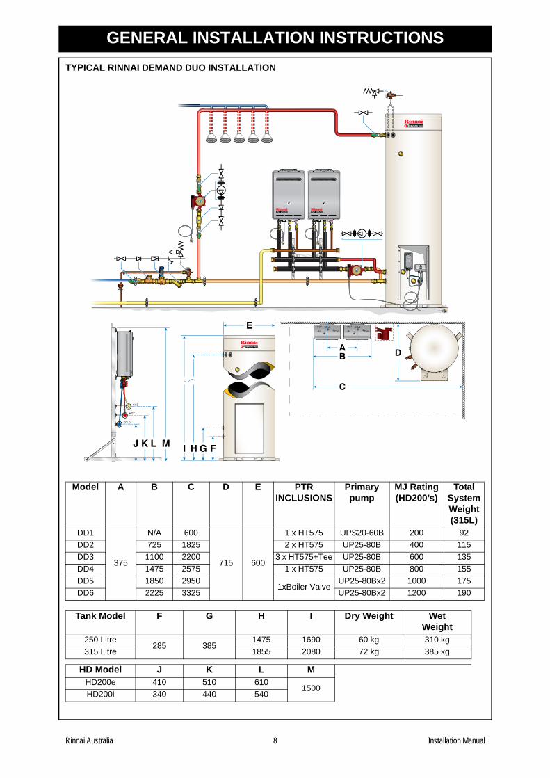
TYPICAL RINNAI DEMAND DUO INSTALLATIONModel A B C D E PTR INCLUSIONS
Primary pump
MJ Rating (HD200’s)
Total System Weight(315L)
DD1
375
N/A 600
715 600
1 x HT575 UPS20-60B 200 92DD2 725 1825 2 x HT575 UP25-80B 400 115DD3 1100 2200 3 x HT575+Tee UP25-80B 600 135DD4 1475 2575 1 x HT575 UP25-80B 800 155DD5 1850 2950
1xBoiler ValveUP25-80Bx2 1000 175
DD6 2225 3325 UP25-80Bx2 1200 190
Tank Model F G H I Dry Weight Wet Weight
250 Litre285 385
1475 1690 60 kg 310 kg315 Litre 1855 2080 72 kg 385 kg
HD Model J K L MHD200e 410 510 610
1500HD200i 340 440 540
65°C
GHI F
A
C
E
B
KJ L M
D
Rinnai Australia 8 Installation Manual
GENERAL INSTALLATION INSTRUCTIONS
Cold Water Supply:• Cold water pipe work to inlet of tank, including required valves as shown above to comply to AS 3500and local regulations.
• Maximum cold water inlet pressure is 650 kPa. Fit pressure limiting valve (rated @ 700 kPa) if coldwater inlet pressure is in excess of 650 kPa.
• For ease of draining, it is advisable to fit a "Tee" piece with a capped valve between the cold waterisolation valve and the cold water inlet connection on the Demand Duo storage cylinder. Tap provided.
Hot Water Outlet • Connect hot water outlet pipe to 32mm fitting on upper left hand side of the storage cylinder with union
and isolation valve as required.• Ensure adequate insulation / lagging is fitted to hot water pipe to minimize heat loss.
Return Pump• A secondary or building return pump may be installed in conjunction with the Rinnai Demand Duo hot
water system. Pump should be sized for minimal temperature loss around the ringmain. Pump musthave a check valve on the discharge.
• Return line from building loop is connected to the cold water supply pipe after the check valve. Fromthat point onwards the cold pipe should be insulated.
Gas Supply• Check gas type of Rinnai Infinity matches gas supply available (LPG or Natural) on job site.• Gas inlet connection is located at the front bottom of the weather shroud on a DD1 and is the top pipe
on a DD2+ manifold.• Appropriate gas isolation valve to be fitted to DD1. DD2+ have gas isolation valves per water heater.• Ensure gas pipe sizing is adequate to deliver the required volume / pressure. Pipe size used on inlet
fitting is no indication of pipe size required.• Refer to appropriate pipe sizing chat in Appendix "F" AS5601 for appropriate sized gas pipe that should
be used to ensure adequate gas supply.• Gas meter / LPG cylinder & regulator should also be of a suitable size to ensure sufficient gas supply to
the gas installation.• Purge gas pipe to ensure removal of debris etc prior to final connection.• Check for gas escapes using suitable methods as listed in Appendix "E" AS 5601.
Filling InstructionsDo Not turn on pump / gas booster before cylinder and water heater are completely full of water.
• Flush cold water inlet pipe to remove any debris before final connection to cold water inlet on RinnaiDemand Duo cylinder.
• Turn on hot water tap to allow air to be expelled while cylinder is filling with cold water.• Slowly open cold water isolation valve on cold water supply pipe.• Allow cylinder to fill. Turn off hot water tap once non-aerated water flows through hot water tap.• Check all connections for water leakage. Tighten as required.• Purge gas lines until gas is available at water heaters.• Prime circulating pump(s) before start up by removing chrome screw and allowing water to drip out the
end of the pump shaft.Starting Instructions
• Turn all GPO's on.• Thermostat will scroll through self check and display will settle on water temperature within the storage
cylinder.• Green LED on thermostat will illuminate when power is available to primary pump when water in tank is
below set temperature. Pump should start. Water flow will cause water heater to start.• For standard systems "75" should appear in the maintenance monitor window on the gas heater. That is
the outlet temperature from the water heater. It must be higher then the thermostat set point. • Thermostat will display temperature of water in tank. When it reaches the 65°C set point the pump and,
therefore, water heater will stop. The display on the water heater will not be lit when not operating.
Rinnai Australia 9 Installation Manual
INSTALLATION HAND OVER MANUAL
Demand Duo Principle of OperationCold water enters the storage tank after passing through an isolation and non return valve.
A tee is fitted to the cold inlet pipe down stream from the non return valve. From this tee, one branch connects tothe lower inlet of the storage tank and the other branch connects to the primary (tank circulation) pump. Thispumps water to the inlet of the infinity(s) heat source. The infinity will only operate when this pump is running.
The heated water from the infinity returns to the tank at the second lowest connection point, located above thecold inlet.
Hot water leaves the tank from the top of the tank. This may be circulated around the building and returned, viaa ringmain pump (set) to the cold inlet before the tee as described above.
When there is a hot water draw off, cold water enters the tank and pushes the hot water out of the tank towardsthe outlet, as per any storage hot water system.
When the temperature in the tank drops below the thermostat set point, the thermostat activates the primarypump(s). They draw water from the cold water feed to the tank, the tank itself, or a combination of both. As statedpreviously, this water is then heated by the infinity and returns to the tank heated. This process is continued untilthe thermostat set point is reached and the pump is switched off.
The outlet temperature setting of the infinity must be set at least three (3) degrees hotter then the thermostat setpoint. Factory settings are: Infinity 75°C, thermostat 65°C.
Demand Duo Preventative MaintenanceAll Items
• Inspect for damage, corrosion or water leaks
Tank• Ensure that tank is not leaking.• Ensure that PTR valves are not leaking. It is normal for PTR valve to operate during the heating cycle,
relieving pressure as the water is expanding. The PTR Valve is rated to 850 kPa and cold inlet pressureshould not exceed 500-700 kPa. If it does, then a pressure reduction valve should be fitted to the cold waterinlet.
• Valve may be operating if water temperature in tank is close to 99°C. If this is the case the thermostat or otherheating equipment has failed to operate correctly. Contact Rinnai service department.
• If pressure and temperature are low but valve is leaking, pull the lever for up to 30 seconds, as some foreignmaterial may be jammed in the valve seat. If valve fails to seat correctly, valve should be replaced. PTRValves are a non-repairable safety device and should be replaced with the correct model and pressure rating.
Thermostat• Check that display is in degrees C and that the flame symbol is showing. This indicated heating mode. A
snowflake means cooling mode and needs to be set properly.• A power surge can reset the thermostat to Fahrenheit. This can be changed back to Celsius by pushing up
and down arrows simultaneously for a few seconds. This can only happen if the jumper inside casing is inprogram position. It is not when it leaves DD factory.
• Check that power is available to system at GPO.• Standard set point is 65°C and differential will be 5°C. • When temperature drops below set point minus differential (eg 65°C - 5°C = 60°C) the green light in the
thermostat will come on.• This sends power to the tank mounted GPO (or direct to the primary pump on a DD1). This will start the
operation of the primary pump(s)• Ensure thermostat sensor is pushed all the way into the well in the tank• Check that power is available at pump or GPO if necessary.
Primary Pump• DD1 = Grundfos UPS20-60B set to speed 3• DD2,3,4 = Grundfos UP 25-80B.• DD5,6 = 2 x Grundfos UP25-80B.• DD1 wired directly to thermostat, DD2,3,4 plugs into switched GPO on tank, DD5,6 two pumps plugged into
double switched GPO in tank.• Some projects may have larger and/or dual pumps for redundancy or long primary pipe run situations.• Pump(s) operate when activated by thermostat, as indicated by green light on thermostat.
Rinnai Australia 10 Installation Manual
INSTALLATION HAND OVER MANUAL
• Ensure that pumps are installed in a weather proof location or protected from being subjected to wateringress. By themselves they are not. Wet pump electrics may cause failure. Water can run along power leadso keep the lead looping under the pump and curving upwards toward the electrical box.
• Ensure shaft is horizontal. DO NOT aim shaft upwards or downwards.• DO NOT locate terminal box under pump housing. Position it on top preferable or on side• Bleed pump with chrome screw at end of pump casing. This will be facing towards you when the
pump shaft is horizontal. Pump runs on water bearing and is critical for life of pump. Excessive noiseindicates damage or lack of bleed.
• When this screw is removed the spinning / stationary impeller shaft can be inspected.• Ensure pump direction of flow arrow is towards infinity(s).• If shaft is spinning but there is no flow: Check ball valves and any non return valve for correct installation and
operation. UP25-80B pumps have inbuilt ball valves in the unions. Line up screwdriver slot parallel to pipe toposition them open.
Infinity Heat Source• Ensure that filter at water inlet is clean. Note that this is an ‘O’ ring seal and does not need to be
excessively tightened. Just make sure ‘O’ ring is engaged inside machined surface in brasshousing. Isolate water supply to DD before removing filter for cleaning & inspection.Ensure water in storage cylinder is not excessively hot before removing Infinity inlet filter.
• Ensure all Infinity's are operating. Ensure power is available to Infinity if it is not operating. Can check GPO.DD1 is hard wired to junction box. DD2+: ensure power is available to the Infinity before applying power tothermostat and pump(s).
• Many new jobs or ones where the gas supply has been modified need to purge the gas supply lines as theyare full of air. Purge should be carried in accordance with AS5601, Appendix 'D'.
• All models up to late 2006: Look at flame through inspection window for conical shape, blue base and yellowtip. Flame height will vary if heater is modulating. Inspection window is located in front cover of appliance.
• All new HD models: when operating the number displayed should be higher than the temperature setting onthe tank mounted thermostat.
• Eg Tank = 65°C, Infinity = 75°C. These are factory standard settings.• Eg Tank = 82°C, Infinity = 85°C. These are the maximum allowable settings.
• All new HD models will display a fault number if one has occurred. Below is a full list of fault codes. • In jobs that operate for long hours and/or in dusty or smoky environments the combustion air fan may become
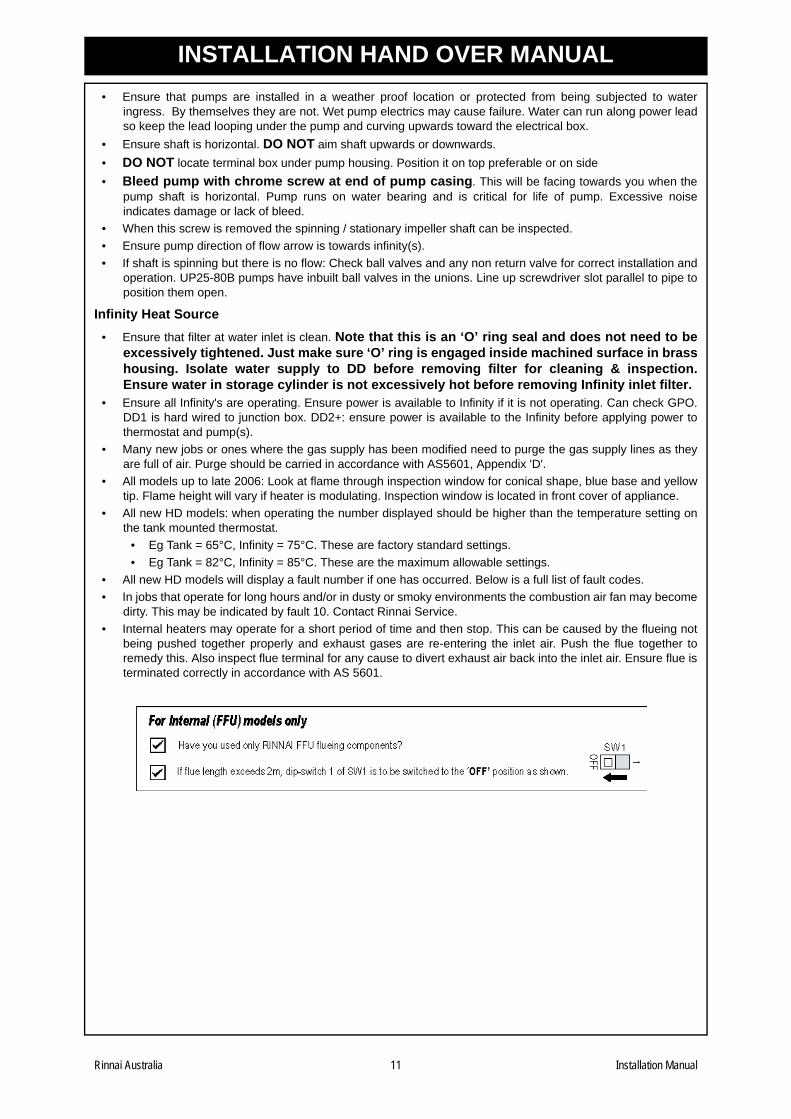
dirty. This may be indicated by fault 10. Contact Rinnai Service. • Internal heaters may operate for a short period of time and then stop. This can be caused by the flueing not
being pushed together properly and exhaust gases are re-entering the inlet air. Push the flue together toremedy this. Also inspect flue terminal for any cause to divert exhaust air back into the inlet air. Ensure flue isterminated correctly in accordance with AS 5601.
Rinnai Australia 11 Installation Manual
INSTALLATION HAND OVER MANUAL
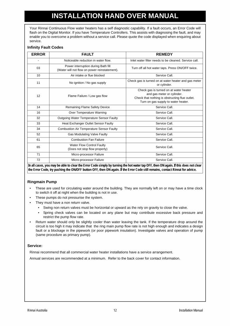
Your Rinnai Continuous Flow water heaters has a self diagnostic capability. If a fault occurs, an Error Code willflash on the Digital Monitor. If you have Temperature Controllers. This assists with diagnosing the fault, and mayenable you to overcome a problem without a service call. Please quote the code displayed when enquiring aboutservice.Infinity Fault Codes
Ringmain Pump• These are used for circulating water around the building. They are normally left on or may have a time clock
to switch it off at night when the building is not in use.• These pumps do not pressurise the system.• They must have a non return valve.
• Swing non return valves must be horizontal or upward as the rely on gravity to close the valve.• Spring check valves can be located on any plane but may contribute excessive back pressure and
restrict the pump flow rate.• Return water should only be slightly cooler than water leaving the tank. If the temperature drop around the
circuit is too high it may indicate that the ring main pump flow rate is not high enough and indicates a designfault or a blockage in the pipework (or poor pipework insulation). Investigate valves and operation of pump(same procedure as primary pump).
Service:Rinnai recommend that all commercial water heater installations have a service arrangement.
Annual services are recommended at a minimum. Refer to the back cover for contact information.
ERROR FAULT REMEDY- Noticeable reduction in water flow. Inlet water filter needs to be cleaned. Service call.
03 Power interruption during Bath fill(Water will not flow on power reinstatement). Turn off all hot water taps. Press ON/OFF twice.
10 Air intake or flue blocked Service Call.
11 No ignition / No gas supply Check gas is turned on at water heater and gas meter or cylinder.
12 Flame Failure / Low gas flow
Check gas is turned on at water heaterand gas meter or cylinder.
Check that nothing is obstructing flue outlet.Turn on gas supply to water heater.
14 Remaining Flame Safety Device Service Call.
16 Over Temperature Warning Service Call.
32 Outgoing Water Temperature Sensor Faulty Service Call.
33 Heat Exchanger Outlet Sensor Faulty Service Call.
34 Combustion Air Temperature Sensor Faulty Service Call.
52 Gas Modulating Valve Faulty Service Call.
61 Combustion Fan Failure Service Call.
65 Water Flow Control Faulty(Does not stop flow properly) Service Call.
71 Micro-processor Failure Service Call.
72 Micro-processor Failure Service Call.
In all cases, you may be able to clear the Error Code simply by turning the hot water tap OFF, then ON again. If this does not clear the Error Code, try pushing the ON/OFF button OFF, then ON again. If the Error Code still remains, contact Rinnai for advice.
Rinnai Australia 12 Installation Manual


14 RA TSD05-011 Demand Duo Issue 1.0 18/12/07
Head Office
10-11 Walker Street,
Braeside, Victoria 3195
P.O. Box 460
Tel: (03) 9271 6625
Fax: (03) 9271 6622
National Help Lines
Spare Parts & Technical Info
Tel: 1300 366 388*
Fax: 1300 300 141**Cost of a local call Higher from mobile or public phones.
Hot Water Service Line
Tel: 1800 000 340
Australia Pty. Ltd. ABN 74 005 138 769 Internet: www.rinnai.com.au E-mail: [email protected]
BARCODE U-PART Nº.
Printed in Japan YYYY.MM123 45678 90123 4
Rinnai has a Service and Spare Parts network with personnel who are fully trained
and equipped to give the best service on your Rinnai appliance. If your appliance
requires a service, please call our Hot Water Service Line. Rinnai recommends that
this appliance be serviced every 3 years.
CONTACT INFORMATION