Embed Size (px)
Citation preview

IM-P198-05 MI Issue 2 1
IM-P198-05 MI Issue 2
1987050/2
1. Safety information
2. Introduction
3. Installation
4. Operating instructions
5. Serial communications
6. Troubleshooting and repair
7. Appendixes
© Copyright 2016
Printed in GB
RIM20 Rotor Insertion Flowmeter
Installation and Maintenance Instructions

IM-P198-05 MI Issue 22
Customer Notice for Oxygen ServiceThis flowmeter is not intended for oxygen service.
Spirax Sarco Limited is not liable for any damage or personal injury, whatsoever, resulting from the use of Spirax Sarco Rotor Insertion Flowmeters for oxygen gas.
If oxygen service is required please consult factory.
1. Safety information1.1 Receipt of System Components 6
1.2 Technical Assistance 6
2. Introduction2.1 RIM20 rotor insertion flowmeters 8
2.2 Multi-Variable Mass flowmeters 8
2.3 Volumetric flowmeters 8
2.4 How the RIM20 rotor flowmeter operates 9
2.5 Velocity measurement 9
2.6 Flow velocity range 9
2.7 Temperature measurement 9
2.8 Pressure measurement 10
2.9 Flowmeter configuration 10
2.10 Multivariable options 10
2.11 Line size / process connections 10
2.12 Flowmeter electronics 11
Customer Notice for EMC Class DivisionThis flowmeter is suitable for EMC Class A environments only.
Class A equipment is suitable for use in all establishments other than domestic and those connected to a low voltage power supply network which supplies
buildings used for domestic purposes.There may be potential difficulties in ensuring electromagnetic compatibility in
other environments, due to conducted as well as radiated disturbances.

IM-P198-05 MI Issue 2 3
3. Installation3.1 Installation overview 12
3.2 Flowmeter installation requirements 12
3.3 Unobstructed flow requirements 12
3.4 Insertion flowmeter installation 14
3.5 Cold tap guidelines 15
3.6 Hot tap guidelines 16
3.7 Flowmeter insertion 18
3.8 Installing flowmeters with a compression connection 19
3.9 Installing flowmeters with a packing gland connection 21
3.10 Installing flowmeters (Packing gland), no insertion tool 26
3.11 Display/Keypad adjustment 28
3.12 Loop power flowmeter wiring connections 29
3.13 Input power connections 30
3.14 4-20 mA output connections 30
3.15 Pulse output connections 31
3.16 Frequency output connections 32
3.17 Optional backlight connections 32
3.18 Remote electronics wiring 33
3.19 High power flowmeter wiring connections 34
3.20 Input power connections 35
3.21 4-20 mA output connections 37
3.22 Frequency output connections 38
3.23 Pulse output connections 40
3.24 Alarm output connections 42
3.25 Remote electronics wiring 44
3.26 Optional input electronics wiring 44
3.27 Optional energy EM RTD input wiring 45
3.28 Optional external 4-20 mA input wiring 45
3.29 Optional contact closure input wiring 46
IM-P198-05 MI Issue 24
4. Operating instructions4.1 Flowmeter display/keypad 47
4.2 Start-up 48
4.3 Using the setup menus 50
4.4 Programming the flowmeter 51
4.5 Output menu 52
4.6 Display menu 53
4.7 Alarms menu 56
4.8 Totalizer #1 menu 58
4.9 Totalizer #2 menu 60
4.10 Energy menu 61
4.11 Fluid menu 62
4.12 Units menu 64
4.13 Time and date menu 65
4.14 Diagnostics menu 66
4.15 Calibration menu 68
4.16 Password menu 69
5. Serial communications5.1 HART communications 70
5.2 Wiring 70
5.3 HART commands with the DD menu 72
5.4 HART commands with generic DD menu 78
5.5 MODBUS communications 82
5.6 Register definitions 85
5.7 BACNET MS/TP communications 91
5.8 Baud rates on the MS/TP Bus 91
5.9 Supported BACnet objects 92
5.10 ANNEX - BACnet protocol implementation conformance statement 98
5.11 Acronyms and definitions 102

IM-P198-05 MI Issue 2 5
6. Troubleshooting and repair6.1 Hidden diagnostics menus 102
6.2 Level one hidden diagnostics values 104
6.3 Level two hidden diagnostics values 106
6.4 Analogue output calibration 108
6.5 Troubleshooting the flowmeter 108
6.6 First check items 108
6.7 Record values 108
6.8 Determine the fault 110
6.9 Electronics assembly replacement 114
6.10 Returning equipment to the factory 114
7. Appendixes7.1 Appendix A Product specifications 115
7.2 Appendix B Approvals 124
7.3 Appendix C flowmeter calculations 125
7.4 Appendix D Glossary 129

IM-P198-05 MI Issue 26
1. Safety informationManufacturers address:Spirax-Sarco LimitedRunnings RoadKingsditch Trading EstateCheltenhamGloucestershireGL51 9NQGB
We use Warning, Caution and Note statements throughout this book to draw your attention to important information.
Warning!This statement appears with information that is important to protect people and equipment from damage. Pay very close attention to all warnings that apply to your application.
Caution!This statement appears with information that is important for protecting your equipment and performance. Read and follow all cautions that apply to your application.
NoteThis statement appears with a short message to alert you to an important detail.
1.1 Receipt of system componentsWhen receiving a Spirax Sarco mass flowmeter, carefully check the outside packing carton for damage incurred in shipment. If the carton is damaged, notify the local carrier and submit a report to the factory or distributor.
Remove the packing slip and check that all ordered components are present. Make sure any spare parts or accessories are not discarded with the packing material. Do not return any equipment to the factory without first contacting Spirax Sarco Customer Service.
1.2 Technical assistanceIf you encounter a problem with your flowmeter, review the configuration information for each step of the installation, operation and set up procedures.
Verify that your settings and adjustments are consistent with factory recommendations. Refer to Section 6, Troubleshooting, for specific information and recommendations.
If the problem persists after following the troubleshooting procedures outlined in Section 6, Contact Spirax Sarco Customer Support between 8:00 a.m. and 5:00 p.m.
When calling Technical Support, have the following information on hand:• the serial number and Spirax Sarco order number (all marked on the meter nameplate)• the problem you are encountering and any corrective action taken• application information (fluid, pressure, temperature and piping configuration)
IM-P198-05 MI Issue 2 7
Warning!Agency approval for hazardous location installations varies between flowmeter models.
Consult the flowmeter nameplate for specific flowmeter approvals before any hazardous location installation.
Hot tapping must be performed by a trained professional, regulations often require a hot tap permit. The manufacturer of the hot tap equipment and/or the contractor performing the hot tap is responsible for providing proof of such a permit.
All flowmeter connections, isolation valves and fittings for cold/hot tapping must have the same or higher pressure rating as the main pipeline.
For RIM20 rotor Insertion flowmeter installations, an Insertion tool must be used for any installation where a flowmeter is inserted under pressure greater than 3.45 bar g (50 psi g).
To avoid serious injury, DO NOT loosen a compression fitting under pressure.
To avoid potential electric shock, follow National Electric Code or your local code when wiring this unit to a power source. Failure to do so could result in injury or death.
All ac power connections must be in accordance with published CE directives. All wiring procedures must be performed with the power Off.
Before attempting any flowmeter repair, verify that the line is not pressurized. Always remove main power before disassembling any part of the mass flowmeter.
Caution!Calibration must be performed by qualified personnel. Spirax Sarco strongly recommends that you return your flowmeter to the factory for calibration.
In order to achieve accurate and repeatable performance, the flowmeter must be installed with the specified minimum length of straight pipe upstream and downstream of the flowmeter’s sensor head.
When using toxic or corrosive gases, purge the line with inert gas for a minimum of four hours at full gas flow before installing the flowmeter.
For RIM20 rotor Insertion flowmeter installations, the sensor alignment pointer must point downstream in the direction of flow.
The ac wire insulation temperature rating must meet or exceed 85 °C (185 °F).

IM-P198-05 MI Issue 28
2. Introduction2.1 RIM20 rotor insertion flowmetersThe Spirax Sarco RIM20 rotor insertion flowmeters provide a reliable solution for process flow measurement. From a single entry point in the pipeline, RIM20 flowmeters offer precise measurements of mass or volumetric flowrates.
2.2 Multi-variable mass flowmetersMass flowmeters utilize three primary sensing elements: a rotating turbine velocity sensor, an RTD temperature sensor, and a solid state pressure sensor to measure the mass flowrate of gases, liquids, and steam. Meters are available as loop powered devices or with up to three 4-20 mA Analogue output signals for monitoring your choice of the six process variables (energy flow, mass flow, volumetric flow, temperature, pressure and fluid density). The Energy Monitoring option permits realtime calculation of energy consumption for a facility or process.
2.3 Volumetric flowmetersThe primary sensing element of a volumetric flowmeter is a rotating turbine velocity sensor. Meters are loop powered. The Analogue 4-20 mA output signal offers your choice of volumetric or mass flowrate. Mass flowrate is based on a constant value for fluid density stored in the instrument’s memory.
Both the mass and volumetric flowmeters can be ordered with a local keypad/display which provides instantaneous flowrate, total, and process parameters in engineering units. A pulse output signal for remote totalization and MODBUS, BACnet or HART communications are also available. RIM20 digital electronics allows for easy reconfiguration for most gases, liquids and steam. The Spirax Sarco RIM20 flowmeters’ simple installation combines with an easy-to-use interface that provides quick set up, long term reliability and accurate mass flow measurement over a wide range of flows, pressures and temperatures.
Fig. 1 Rotor Insertion multivariable Mass flowmeters
IM-P198-05 MI Issue 2 9
2.4 How the RIM20 rotor insertion flowmeter operatesThe RIM20 rotor insertion flowmeters are designed to monitor mass flowrate by directly measuring three variables-fluid velocity, temperature and pressure. The built-in flow computer calculates the mass flowrate and volumetric flowrate based on these three direct measurements. To measure fluid velocity, the flowmeter incorporates a rotating turbine in the flow stream. The rotation is converted into an electrical output which is proportional to fluid velocity.
Temperature is measured using a platinum resistance temperature detector (PRTD) and pressure measurement is achieved using a solid-state pressure transducer.
2.5 Velocity measurementFluid passing through the turbine causes its rotor to spin. The rotor is fabricated from 17-4PH stainless steel which is slightly magnetic, and is positioned in close proximity to a passive magnetic pickup coil. As each blade rotates by the pickup coil, a small sinusoidal voltage is generated. This sinusoidal voltage is then amplified, filtered, and shaped by the measurement electronics. The frequency of the signal is proportional to the flowing velocity.
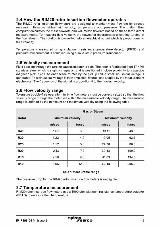
2.6 Flow velocity rangeTo ensure trouble-free operation, turbine flowmeters must be correctly sized so that the flow velocity range through the meter lies within the measurable velocity range. The measurable range is defined by the minimum and maximum velocity using the following table.
Rotor
Gas or Steam
Minimum velocity Maximum velocity
m/sec ft/sec m/sec ft/sec
R40 1.07 3.5 13.11 43.0
R30 1.22 4.0 19.05 62.5
R25 1.52 5.0 24.38 80.0
R20 2.13 7.0 30.48 100.0
R15 2.59 8.5 41.03 134.6
R10 3.66 12.0 62.48 205.0
Table 1 Measurable range
The pressure drop for the RIM20 rotor insertion flowmeters is negligible.
2.7 Temperature measurementRIM20 rotor insertion flowmeters use a 1000 ohm platinum resistance temperature detector (PRTD) to measure fluid temperature.

IM-P198-05 MI Issue 210
2.8 Pressure measurementThe RIM20 rotor insertion flowmeters incorporate a solid-state pressure transducer isolated by a 316L stainless steel diaphragm. The transducer itself is micromachined silicon, fabricated using integrated circuit processing technology.
A nine-point pressure/temperature calibration is performed on every sensor. Digital compensation allows these transducers to operate within a 0.3% of full scale accuracy band within the entire ambient temperature range of -40 to 60 °C (-40 °F to 140 °F). Thermal isolation of the pressure transducer ensures the same accuracy across the allowable process fluidtemperature range of -200 to 400 °C (-330 °F to 750 °F).
2.9 Flowmeter configurationThe RIM20 rotor insertion flowmeters has a sensing head which contains the turbine rotor, temperature sensor, and pressure tap.
The pressure sensor is located in the pressure transducer housing between the stem and electronics housing.
The meter is installed through a full port block valve and mounting adapter having a clear, cylindrical port diameter of 47.625 mm (1.875") diameter. It can be installed during system downtime or using standard "Hot Tap" procedures.
The meter directly monitors the velocity at a point in the cross-sectional area of a pipe, duct, or stack. The velocity at a point in the pipe varies as a function of the Reynolds number. When a fluid flows through a pipe, the velocity generated is not constant across the diameter. The fluid velocity varies across the diameter of the pipe creating a "Velocity Profile".
That is, velocities near the center of the pipe are faster than those nearer to the wall. In addition, the velocity profile varies in concert with flowrate from the lowest to the highest flows. Mathematical descriptions of this profile have been developed for over 100 years. By knowing the velocity profile and the flowrate at a single point, the average flowrate can be determined. The accuracy of the flowrate computation depends on adherence to the piping installation requirements given in Section 2. If adherence to those guidelines cannot be met, contact the factory for specific installation advice.
2.10 Multivariable optionsThe RIM20 model is available with the following options:V, volumetric flowmeter; VT, velocity and temperature sensors; VTP, velocity, temperature, and pressure sensors; VTEM energy output options; VTPEM, energy options with pressure; VTEP, external pressure transmitter input.
2.11 Line size / process connectionsThe RIM20 rotor insertion flowmeter can be used in line sizes DN50 (2") and greater and is built with a compression fitting or packing gland design using 50 mm (2") NPT, or DN50 (2") flanged connections (ANSI 150, 300, 600, PN16, 40, or 63 class flanges). The packing gland design can be ordered with a permanent or removable retractor.

IM-P198-05 MI Issue 2 11
2.12 Flowmeter electronicsRIM20 flowmeter electronics are available mounted directly to the flowmeter, or remotely mounted. The electronics housing may be used indoors or outdoors, including wet environments. Available input power options are: dc loop powered (2-wire), dc powered, or ac powered.
Three Analogue output signals are available for your choice of three of the six process variables: energy flowrate, mass flowrate, volumetric flowrate, temperature, pressure or fluid density. A pulse output signal for remote totalization and MODBUS, BACnet or HART communications are also available.
RIM20 flowmeters include a local 2 x 16 character LCD display housed within the enclosure. Local operation and reconfiguration is accomplished using six pushbuttons operated via finger touch. For hazardous locations, the six buttons can be operated with the electronics enclosuresealed using a hand-held magnet, thereby not compromising the integrity of the hazardous location certification.
The electronics include nonvolatile memory that stores all configuration information. The nonvolatile memory allows the flowmeter to function immediately upon power up, or after an interruption in power. All flowmeters are calibrated. The instrument is configured for the customer’s flow application.
IM-P198-05 MI Issue 212
3.1 Installation overviewThe RIM20 rotor insertion flowmeter installations are simple and straightforward. After reviewing the installation requirements given below, see Section 3.4 for RIM20 installation instructions.
Warning!Consult the flowmeter nameplate for specific flowmeter approvals before any hazardous location installation.
3.2 Flowmeter installation requirementsBefore installing the flowmeter, verify the installation site allows for these considerations:
1. Line pressure and temperature will not exceed the flowmeter rating.
2. The location meets the required minimum number of pipe diameters upstream and downstream of the sensor head as illustrated in Figure 2.
3. Safe and convenient access with adequate overhead clearance for maintenance purposes.
4. Verify that the cable entry into the instrument meets the specific standard required for hazardous area installations. The cable entry device shall be of a certified flameproof type, suitable for the conditions of use and correctly installed. The degree of protection of at least IP66 to EN 60529 is only achieved if certified cable entries are used that are suitable for the application and correctly installed. Unused apertures shall be closed with suitable blanking elements.
5. For remote installations, verify the supplied cable length is sufficient to connect the flowmeter sensor to the remote electronics.
Also, before installation check your flow system for anomalies such as:
- leaks
- valves or restrictions in the flow path that could create disturbances in the flow profile that might cause unexpected flowrate indications
- avoid areas where high RF, EMI, or other electrical interference may be present. Devices such as VFD's (variable frequency drives), large ac motors, etc.
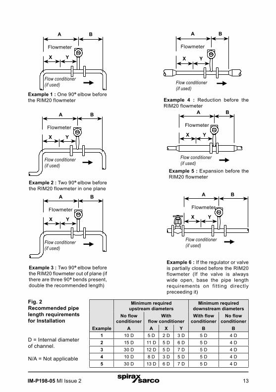
3.3 Unobstructed flow requirementsSelect an installation site that will minimize possible distortion in the flow profile. Valves, elbows, control valves and other piping components may cause flow disturbances. Check your specific piping condition against the examples shown below. In order to achieve accurate and repeatable performance install the flowmeter using the recommended number of straight run pipe diameters upstream and downstream of the sensor.
Note: For liquid applications in vertical pipes, avoid installing with flow in the downward direction because the pipe may not be full at all points.
Choose to install the meter with flow in the upward direction if possible.
3. Installation
IM-P198-05 MI Issue 2 13
Example
Minimum required upstream diameters
Minimum required downstream diameters
No flow conditioner
With flow conditioner
With flow conditioner
No flow conditioner
A A X Y B B1 10 D 5 D 2 D 3 D 5 D 4 D2 15 D 11 D 5 D 6 D 5 D 4 D3 30 D 12 D 5 D 7 D 5 D 4 D4 10 D 8 D 3 D 5 D 5 D 4 D5 30 D 13 D 6 D 7 D 5 D 4 D
A B
Flowmeter
A B
X Y
Example 1 : One 90º elbow before the RIM20 flowmeter Example 4 : Reduction before the
RIM20 flowmeter
Flowmeter
Flowmeter
A B
X Y
Example 2 : Two 90º elbow before the RIM20 flowmeter in one plane
Flowmeter
A B
X Y
Example 5 : Expansion before the RIM20 flowmeter
Flowmeter
A B
X Y
Example 3 : Two 90º elbow before the RIM20 flowmeter out of plane (if there are three 90º bends present, double the recommended length)
Flowmeter
A B
X Y
Example 6 : If the regulator or valve is partially closed before the RIM20 flowmeter (If the valve is always wide open, base the pipe length requirements on f it t ing directly preceeding it)
Flow conditioner(if used)
X Y
Fig. 2 Recommended pipe length requirements for Installation
D = Internal diameter of channel.
N/A = Not applicable
Flow conditioner(if used)
Flow conditioner(if used)
Flow conditioner(if used)
Flow conditioner(if used)
Flow conditioner(if used)

IM-P198-05 MI Issue 214
3.4 Insertion flowmeter installationPrepare the pipeline for installation using either a cold tap or hot tap method described on the following pages. Refer to a standard code for all pipe tapping operations. The following tapping instructions are general in nature and intended for guideline purposes only. Before installing the meter, review the mounting position and isolation value requirements given below.
3.4.1 Mounting positionAllow clearance between the electronics enclosure top and any other obstruction when the meter is fully retracted.
3.4.2 Isolation valve selectionAn isolation valve is available as an option with RIM20 flowmeters. If you supply the isolation valve, it must meet the following requirements:
1. A minimum valve bore diameter of 47.625 mm (1.875") is required, and the valve's body size should be DN50 (2"). Normally, gate valves are used.
2. Verify that the valve's body and flange rating are within the flowmeter's maximum operating pressure and temperature.
3. Choose an isolation valve with at least 50 mm (2") existing between the flange face and the gate portion of the valve. This ensures that the flowmeter's sensor head will not interfere with the operation of the isolation valve.
Fig. 3 Isolation valve requirements
50 mm (2") minimum
47.625 mm (1.875") minimum valve bore
DN50 (2") valve size
IM-P198-05 MI Issue 2 15
3.5 Cold tap guidelinesRefer to a standard code for all pipe tapping operations. The following tapping instructions are general in nature and intended for guideline purposes only.
Caution!When using toxic or corrosive gases, purge the line with inert gas for a minimum of four hours at full gas flow before installing the flowmeter.
Warning!All flowmeter connections, isolation valves and fittings for cold tapping must have the same or higher pressure rating as the main pipeline.
1. Turn off the flow of process gas, liquid or steam. Verify that the line is not pressurised.
2. Confirm that the installation site meets the minimum upstream and downstream pipe diameter requirements. See Figure 2.
3. Use a cutting torch or sharp cutting tool to tap into the pipe. The pipe opening must be at least 47.625 mm (1.875") in diameter. (Do not attempt to insert the sensor probe through a smaller hole.)
4. Remove all burrs from the tap. Rough edges may cause flow profile distortions that could affect flowmeter accuracy. Also, obstructions could damage the sensor assembly when inserting into the pipe.
5. After cutting, measure the thickness of the cut-out and record this number for calculating the insertion depth.
6. Weld the flowmeter pipe connection on the pipe. Make sure this connection is within ±5° perpendicular to the pipe centerline.
7. Install the isolation valve (if used).
8. When welding is complete and all fittings are installed, close the isolation valve or cap the line. Run a static pressure check on the welds. If pressure loss or leaks are detected, repair the joint and retest.
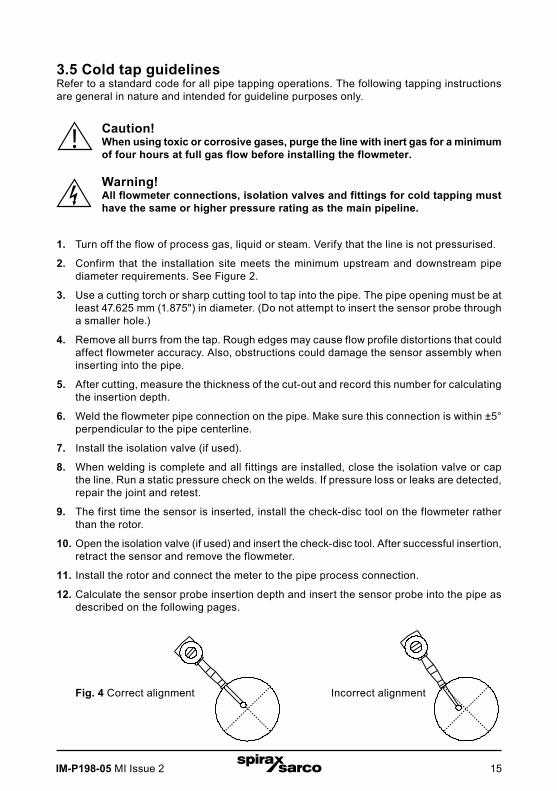
9. The first time the sensor is inserted, install the check-disc tool on the flowmeter rather than the rotor.
10. Open the isolation valve (if used) and insert the check-disc tool. After successful insertion, retract the sensor and remove the flowmeter.
11. Install the rotor and connect the meter to the pipe process connection.
12. Calculate the sensor probe insertion depth and insert the sensor probe into the pipe as described on the following pages.
Fig. 4 Correct alignment Incorrect alignment
IM-P198-05 MI Issue 216
3.6 Hot tap guidelinesRefer to a standard code for all pipe tapping operations. The following tapping instructions are general in nature and intended for guideline purposes only.
Warning!Hot tapping must be performed by a trained professional. US. regulations often require a hot tap permit. The manufacturer of the hot tap equipment and/or the contractor performing the hot tap is responsible for providing proof of such a permit.
Warning!All flowmeter connections, isolation valves, and fittings for hot tapping must have the same or higher pressure rating as the main pipeline.
1. Confirm that the installation site meets the minimum upstream and downstream pipe diameter requirements.
2. Weld a two" mounting adapter on the pipe. Make sure the mounting adapter is within ±5° perpendicular to the pipe centerline (see previous page). The pipe opening must be at least 47.625 mm (1.875") in diameter.
3. Connect a two" process connection on the mounting adapter.
4. Connect an isolation valve on the process connection. The valve's full open bore must be at least 47.625 mm (1.875") in diameter.
5. Run a static pressure check on the welds. If pressure loss or leaks are detected, repair the joint and re-test.
6. Connect the hot tapping equipment to the isolation valve, open the isolation valve and drill at least a 47.625 mm (1.875") diameter hole.
7. Retract the drill, close the isolation valve, and remove the hot tapping equipment.
8. The first time the sensor is installed, install the check-disc tool on the flowmeter rather than the rotor.
9. Open the isolation valve and insert the check-disc tool. After successful insertion, retract the sensor, close the isolation valve and remove the flowmeter.
10. Install the rotor, connect the flowmeter to the isolation valve and open the isolation valve.
11. Calculate the sensor probe insertion depth and insert the sensor probe into the pipe as described on the following pages.

IM-P198-05 MI Issue 2 17
Fig. 5 Hot tap sequence
Check upstream and downstream requirements
Weld mounting adapter
Connect process connection (flange or NPT)
Connect isolation valve and test for leaks
Hot tap pipe
Purge pipe
Connect meter to valve, calculate insertion depth, install flowmeter
IM-P198-05 MI Issue 218
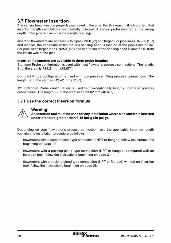
3.7 Flowmeter InsertionThe sensor head must be properly positioned in the pipe. For this reason, it is important that insertion length calculations are carefully followed. A sensor probe inserted at the wrong depth in the pipe will result in inaccurate readings.
insertion flowmeters are applicable to pipes DN50 (2") and larger. For pipe sizes DN250 (10") and smaller, the centerline of the meter's sensing head is located at the pipe's centerline. For pipe sizes larger than DN250 (10"), the centerline of the sensing head is located 5" from the inside wall of the pipe.
Insertion flowmeters are available in three probe lengths:Standard Probe configuration is used with most flowmeter process connections. The length, S, of the stem is 728.21 mm (28.67").
Compact Probe configuration is used with compression fitting process connections. The length, S, of the stem is 312.42 mm (12.3").
12" Extended Probe configuration is used with exceptionally lengthy flowmeter process connections. The length, S, of the stem is 1 033.02 mm (40.67").
3.7.1 Use the correct Insertion formula
Warning!An Insertion tool must be used for any installation where a flowmeter is inserted under pressure greater than 3.45 bar g (50 psi g).
Depending on your flowmeter's process connection, use the applicable insertion length formula and installation procedure as follows:
- flowmeters with a compression type connection (NPT or flanged) follow the instructions beginning on page 19.
- flowmeters with a packing gland type connection (NPT or flanged) configured with an insertion tool, follow the instructions beginning on page 21.
- flowmeters with a packing gland type connection (NPT or flanged) without an insertion tool, follow the instructions beginning on page 26.

IM-P198-05 MI Issue 2 19
3.8 Installing flowmeters with a compression connection*Use the following formula to determine insertion length for flowmeters (NPT and flanged) with a compression process connection. The installation procedure is given on the next page.
Insertion length formulaI = S - F - R - t
Where:I = insertion length.S = Stem length - the distance from the center of the sensor head to the base of the
enclosure adapterS = 728.218 mm (28.67") for standard probes; S = 312.42 mm (12.3") for compact; S = 1 033.02 mm (40.67") for 304.8 mm (12") extended.
F = Distance from the raised face of the flange or top of NPT stem housing to the outside of the pipe wall.
R = Pipe inside diameter ÷ 2 for pipes DN250 (10") and smaller.R = 125 mm (5") for pipe diameters larger than DN250 (10").t = Thickness of the pipe wall. (Measure the disk cut-out from the tapping procedure or
check a piping handbook for thickness.)
Fig. 6 Insertion calculation (compression type)
Example:To install a RIM20 meter with a standard probe (S = 728.218 mm (28.67")) into a DN350 (14") schedule 40 pipe, the following measurements are taken:
F = 76.2 mm (3") R = 127 mm (5") t = 11.125 mm (0.438")
The insertion length for this example is 513.842 mm (20.23"). Insert the stem through the fitting until an insertion length of 513.842 mm (20.23") is measured with a ruler.
*All dimensions are in mm
(inches)
S
I
F
R
t
Flow
S
I
F
R
t
Flow
IM-P198-05 MI Issue 220
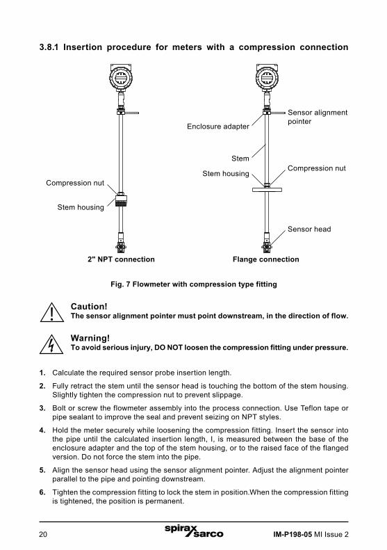
3.8.1 Insertion procedure for meters with a compression connection
Fig. 7 Flowmeter with compression type fitting
Caution!The sensor alignment pointer must point downstream, in the direction of flow.
Warning!To avoid serious injury, DO NOT loosen the compression fitting under pressure.
1. Calculate the required sensor probe insertion length.
2. Fully retract the stem until the sensor head is touching the bottom of the stem housing. Slightly tighten the compression nut to prevent slippage.
3. Bolt or screw the flowmeter assembly into the process connection. Use Teflon tape or pipe sealant to improve the seal and prevent seizing on NPT styles.
4. Hold the meter securely while loosening the compression fitting. Insert the sensor into the pipe until the calculated insertion length, I, is measured between the base of the enclosure adapter and the top of the stem housing, or to the raised face of the flanged version. Do not force the stem into the pipe.
5. Align the sensor head using the sensor alignment pointer. Adjust the alignment pointer parallel to the pipe and pointing downstream.
6. Tighten the compression fitting to lock the stem in position.When the compression fitting is tightened, the position is permanent.
Compression nut
Stem housing
Sensor alignment pointer
Stem
Enclosure adapter
Stem housingCompression nut
Sensor head
2" NPT connection Flange connection
IM-P198-05 MI Issue 2 21
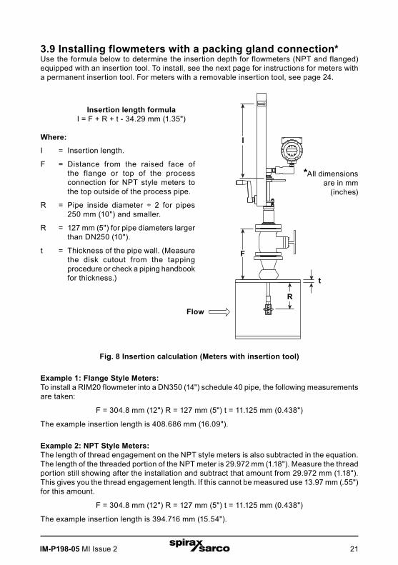
3.9 Installing flowmeters with a packing gland connection*Use the formula below to determine the insertion depth for flowmeters (NPT and flanged) equipped with an insertion tool. To install, see the next page for instructions for meters with a permanent insertion tool. For meters with a removable insertion tool, see page 24.
Fig. 8 Insertion calculation (Meters with insertion tool)
Example 1: Flange Style Meters:To install a RIM20 flowmeter into a DN350 (14") schedule 40 pipe, the following measurements are taken:
F = 304.8 mm (12") R = 127 mm (5") t = 11.125 mm (0.438")
The example insertion length is 408.686 mm (16.09").
Example 2: NPT Style Meters:The length of thread engagement on the NPT style meters is also subtracted in the equation. The length of the threaded portion of the NPT meter is 29.972 mm (1.18"). Measure the thread portion still showing after the installation and subtract that amount from 29.972 mm (1.18"). This gives you the thread engagement length. If this cannot be measured use 13.97 mm (.55") for this amount.
F = 304.8 mm (12") R = 127 mm (5") t = 11.125 mm (0.438")
The example insertion length is 394.716 mm (15.54").
Insertion length formulaI = F + R + t - 34.29 mm (1.35")
Where:
I = Insertion length.
F = Distance from the raised face of the flange or top of the process connection for NPT style meters to the top outside of the process pipe.
R = Pipe inside diameter ÷ 2 for pipes 250 mm (10") and smaller.
R = 127 mm (5") for pipe diameters larger than DN250 (10").
t = Thickness of the pipe wall. (Measure the disk cutout from the tapping procedure or check a piping handbook for thickness.)
FLOW
EXIT EN TER
*All dimensions are in mm
(inches)
I
F
R
t
Flow
IM-P198-05 MI Issue 222
EXIT ENTER
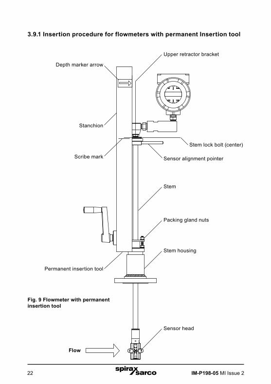
3.9.1 Insertion procedure for flowmeters with permanent Insertion tool
Fig. 9 Flowmeter with permanent insertion tool
Depth marker arrow
Stanchion
Scribe mark
Permanent insertion tool
Flow
Upper retractor bracket
Stem lock bolt (center)
Sensor alignment pointer
Stem
Packing gland nuts
Stem housing
Sensor head

IM-P198-05 MI Issue 2 23
Caution!The sensor alignment pointer must point downstream, in the direction of flow.
NoteIf line pressure is above 34.47 bar g (500 psi g), it could require up to 33.895 N-m (25 ft lb) of torque to insert the flowmeter.Do not confuse this with possible interference in the pipe.
1. Calculate the required sensor probe insertion length (see previous page). Measure from the depth marker arrow down the stanchion and scribe a mark at the calculated insertion depth.
2. Fully retract the flowmeter until the sensor head is touching the bottom of the stem housing. Attach the meter assembly to the DN50 (2") full-port isolation valve, if used. Use Teflon tape or pipe sealant to improve seal and prevent seizing on NPT style.
3. Loosen the two packing gland nuts on the stem housing of the meter.
Loosen the stem lock bolt adjacent to the sensor alignment pointer. Align the sensor head using the sensor alignment pointer. Adjust the alignment pointer parallel to the pipe and pointing downstream. Tighten the stem lock bolt to secure the sensor position.
4. Slowly open the isolation valve to the full open position. If necessary, slightly tighten the two packing gland nuts to reduce the leakage around the stem.
5. Turn the insertion tool handle clockwise to insert the sensor head into the pipe. Continue until the top of the upper retractor bracket aligns with the insertion length position scribed on the stanchion. Do not force the stem into the pipe.
6. Tighten the packing gland nuts to stop leakage around the stem. Do not torque over 27.116 N-m (20 ft-lb).
IM-P198-05 MI Issue 224
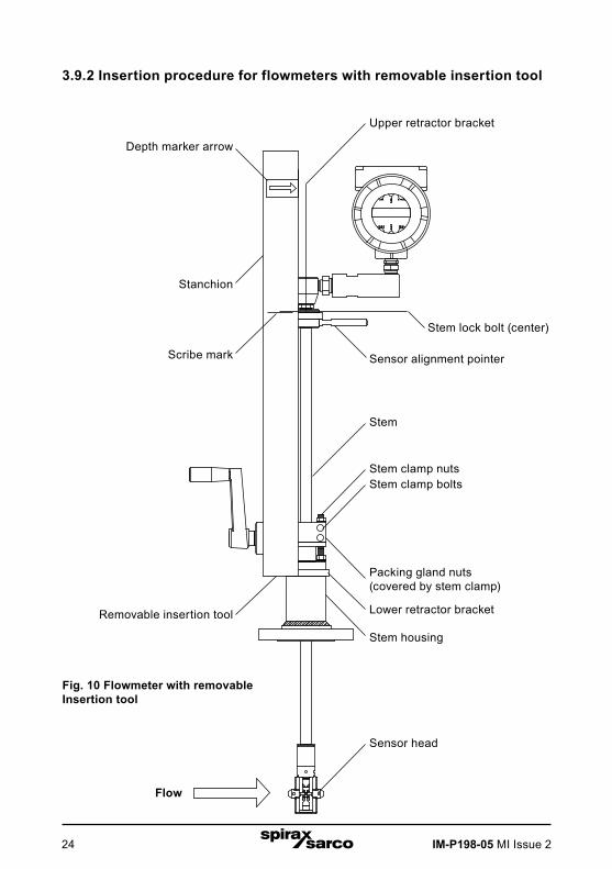
3.9.2 Insertion procedure for flowmeters with removable insertion tool
Fig. 10 Flowmeter with removable Insertion tool
Depth marker arrow
Stanchion
Scribe mark
Removable insertion tool
Flow
Upper retractor bracket
Stem lock bolt (center)
Sensor alignment pointer
Stem
Packing gland nuts(covered by stem clamp)
Stem housing
Sensor head
Lower retractor bracket
Stem clamp boltsStem clamp nuts
IM-P198-05 MI Issue 2 25
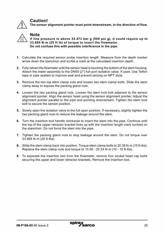
Caution!The sensor alignment pointer must point downstream, in the direction of flow.
NoteIf line pressure is above 34.473 bar g (500 psi g), it could require up to 33.895 N-m (25 ft lb) of torque to insert the flowmeter.Do not confuse this with possible interference in the pipe.
1. Calculate the required sensor probe insertion length. Measure from the depth marker arrow down the stanchion and scribe a mark at the calculated insertion depth.
2. Fully retract the flowmeter until the sensor head is touching the bottom of the stem housing. Attach the meter assembly to the DN50 (2") full-port isolation valve, if used. Use Teflon tape or pipe sealant to improve seal and prevent seizing on NPT style.
3. Remove the two top stem clamp nuts and loosen two stem clamp bolts. Slide the stem clamp away to expose the packing gland nuts.
4. Loosen the two packing gland nuts. Loosen the stem lock bolt adjacent to the sensor alignment pointer. Align the sensor head using the sensor alignment pointer. Adjust the alignment pointer parallel to the pipe and pointing downstream. Tighten the stem lock bolt to secure the sensor position.
5. Slowly open the isolation valve to the full open position. If necessary, slightly tighten the two packing gland nuts to reduce the leakage around the stem.
6. Turn the insertion tool handle clockwise to insert the stem into the pipe. Continue until the top of the upper retractor bracket lines up with the insertion length mark scribed on the stanchion. Do not force the stem into the pipe.
7. Tighten the packing gland nuts to stop leakage around the stem. Do not torque over 33.895 N-m (20 ft-lbs).
8. Slide the stem clamp back into position. Torque stem clamp bolts to 20.38 N-m (15 ft-lbs). Replace the stem clamp nuts and torque to 13.56 - 20.34 N-m (10 - 15 ft-lbs).
9. To separate the insertion tool from the flowmeter, remove four socket head cap bolts securing the upper and lower retractor brackets. Remove the insertion tool.

IM-P198-05 MI Issue 226
3.10 Installation of meters with packing gland connection (No Insertion Tool)*Use the following formula to determine insertion depth for meters with a packing gland connection (NPT and flanged) without an insertion tool.
Fig. 11 Insertion calculation (Meters without insertion tool)
Example:To install a RIM20 flowmeter with a standard probe (S = 728.218 mm (28.67")) into a DN350 (14") schedule 40 pipe, the following measurements are taken:
F = 76.2 mm (3") R = 127 mm (5") t = 11.125 mm (0.438")
The example insertion length is 513.842 mm (20.23").
Insertion length formulaI = S - F - R - t
Where:
I = Insertion length.
S = Stem length - the distance from the center of the sensor head to the base of the enclosure adapter
S = 728.218 mm (28.67") for standard probes;
S = 1 033.02 mm (40.67") for 304.8 mm (12") extended probes.
F = Distance from the raised face of the flange or top of NPT stem housing to the outside of the pipe wall.
R = Pipe inside diameter ÷ 2 for pipes DN250 (10") and smaller.
R = 127 mm (5") for pipe diameters larger than 250 mm (10").
t = Thickness of the pipe wall. (Measure the disk cut-out from the tapping procedure or check a piping handbook for thickness.)
*All dimensions are in mm
(inches)
EXIT EN T ER
I
F
R
t
Flow
S

IM-P198-05 MI Issue 2 27
3.10.1 Insertion procedure for flowmeters with no insertion tool (Packing gland connection)
Warning!The line pressure must be less than 3.48 bar g (50 psi g) for installation.
Caution!The sensor alignment pointer must point downstream, in the direction of flow.
1. Calculate the required sensor probe insertion length.
2. Fully retract the stem until the sensor head is touching the bottom of the stem housing. Remove the two top stem clamp nuts and loosen two stem clamp bolts. Slide the stem clamp away to expose the packing gland nuts. Loosen the two packing gland nuts.
3. Align the sensor head using the sensor alignment pointer. Adjust the alignment pointer parallel to the pipe and pointing downstream.
4. Insert the sensor head into the pipe until insertion length, I, is achieved. Do not force the stem into the pipe.
5. Tighten the packing gland nuts to stop leakage around the stem. Do not torque over 27.116 N-m (20 ft-lbs).
6. Slide the stem clamp back into position. Torque stem clamp bolts to 20.337 N-m (15 ft-lbs). Replace the stem clamp nuts and torque to 13.56 - 20.337 N-m (10 - 15 ft-lbs).
IM-P198-05 MI Issue 228
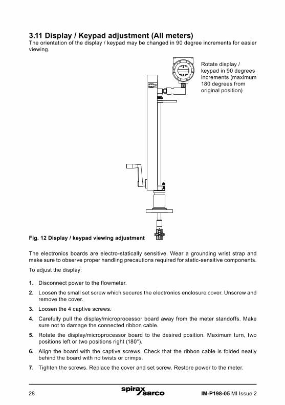
3.11 Display / Keypad adjustment (All meters)The orientation of the display / keypad may be changed in 90 degree increments for easier viewing.
Fig. 12 Display / keypad viewing adjustment
The electronics boards are electro-statically sensitive. Wear a grounding wrist strap and make sure to observe proper handling precautions required for static-sensitive components.
To adjust the display:
1. Disconnect power to the flowmeter.
2. Loosen the small set screw which secures the electronics enclosure cover. Unscrew and remove the cover.
3. Loosen the 4 captive screws.
4. Carefully pull the display/microprocessor board away from the meter standoffs. Make sure not to damage the connected ribbon cable.
5. Rotate the display/microprocessor board to the desired position. Maximum turn, two positions left or two positions right (180°).
6. Align the board with the captive screws. Check that the ribbon cable is folded neatly behind the board with no twists or crimps.
7. Tighten the screws. Replace the cover and set screw. Restore power to the meter.
Rotate display / keypad in 90 degrees increments (maximum 180 degrees from original position)

IM-P198-05 MI Issue 2 29
3.12 Loop power flowmeter wiring connections
Warning!To avoid potential electric shock, follow National Electric Code safety practices or your local code when wiring this unit to a power source and to peripheral devices. Failure to do so could result in injury or death. All wiring procedures must be performed with the power off.
The NEMA 4X enclosure contains an integral wiring compartment located in the smaller end of the enclosure. Two 3/4-inch female NPT conduit entries are available for separate power and signal wiring. For all hazardous area installations, make sure to use an agency-approved fitting at each conduit entry. The cable entry device shall be of a certified flameproof type, suitable for the conditions of use and correctly installed. The degree of protection of at least IP66 to EN 60529 is only achieved if certified cable entries are used that are suitable for the application and correctly installed.
Unused apertures shall be closed with suitable blanking elements.
If conduit seals are used, they must be installed within 457 mm (18") of the enclosure.
Fig. 13 Loop power wiring terminals

IM-P198-05 MI Issue 230
Fig. 14 dc power connections
3.13 Input power connectionsTo access the wiring terminal blocks, locate and loosen the small set screw which locks the small enclosure cover in place. Unscrew the cover to expose the terminal block.
3.13.1 dc power wiringConnect 4-20 mA loop power (12 to 36 Vdc at 25 mA, 1W max.) to the +Loop Power and -Loop Power terminals on the terminal block.
Torque all connections to 0.5 to 0.6 N-m (4.43 to 5.31 in lbs).
The dc power wire size must be 20 to 10 AWG with the wire stripped 7 mm (¼").
Fig. 15 Load Resistance Versus Input Voltage
3.14 4-20 mA output connectionsThe RIM20 flowmeter has a single 4-20 mA loop. The 4-20 mA loop current is controlled by the meter electronics. The electronics must be wired in series with the sense resistor or current meter. The current control electronics require 12 volts at the input terminals to operate correctly.
The maximum loop resistance (load) for the current loop output is dependent upon the supply voltage and is given in Figure 14. The 4-20 mA loop is optically isolated from the flowmeter electronics.
Rload is the total resistance in the loop, including the wiring resistance (Rload = Rwire + Rsense). To calculate Rmax, the maximum Rloadfor the loop, subtract the minimum terminal voltage from the supply voltage and divide by the maximum loop current, 20 mA. Thus:
The maximum resistance Rload = Rmax = (Vsupply - 12V) / 0.020 A
Rload
12 to 36 VDC25 mA max.
+ Pwr
- Pwr
Rlo
ad (o
hmns
)
VSupply (volts)
Operating range
Vsupply (volts)
Rlo
ad (o
hmns
)
12 to 36 Vdc25 mA max.
+ Pwr
- Pwr
Operating range

IM-P198-05 MI Issue 2 31
3.15 Pulse output connectionsThe pulse output is used for a remote counter. When the preset volume or mass (defined in the totalizer settings, see Section 4) has passed the meter, the output provides a 50 millisecond square pulse.
The pulse output requires a separate 5 to 36 Vdc power supply. The pulse output optical relay is a normally-open single-pole relay. The relay has a nominal 200 volt/160 ohm rating. This means that it has a nominal on-resistance of 160 ohms, and the largest voltage that it can withstand across the output terminals is 200 volts. However, there are current and power specifications that must be observed. The relay can conduct a current up to 40 mA and can dissipate up to 320 mW. The relay output is isolated from the meter electronics and power supply.
Fig. 16 Isolated pulse output using external power
Fig. 17 Non-isolated pulse output using external power supply
+V
R current limit - 10 k
Pulse +
Pulse -
Pulse voltage = +VSelect resistor so that current through pulse 40 mA
R current limit - 10 k
DC power
DC common
Pulse +
Pulse -
+ Pwr Bklt
- Pwr Bklt
Pulse voltage = +VSelect resistor so that current through pulse 40 mA
dc power dc common
Pulse voltage = +VSelect resistor so that currentthrough pulse 40 mA
R current limit - 10 k
Pulse +
Pulse -
Pulse +
Pulse -
+ Pwr Bklt
- Pwr Bklt
Pulse voltage = +VSelect resistor so that current through pulse 40 mA
R current limit - 10 k
IM-P198-05 MI Issue 232
R current limit - 10 k
DC power
DC common
Freq. Out +
Freq. Out -
+ Pwr Bklt
- Pwr Bklt
Freq. Out voltage = +VSelect resistor so that current through pulse 40 mA
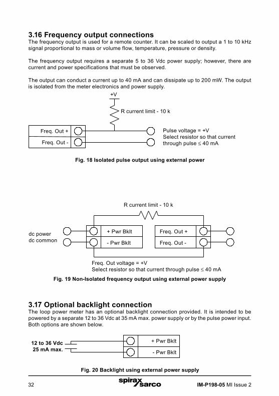
3.16 Frequency output connectionsThe frequency output is used for a remote counter. It can be scaled to output a 1 to 10 kHz signal proportional to mass or volume flow, temperature, pressure or density.
The frequency output requires a separate 5 to 36 Vdc power supply; however, there are current and power specifications that must be observed.
The output can conduct a current up to 40 mA and can dissipate up to 200 mW. The output is isolated from the meter electronics and power supply.
Fig. 19 Non-Isolated frequency output using external power supply
3.17 Optional backlight connectionThe loop power meter has an optional backlight connection provided. It is intended to be powered by a separate 12 to 36 Vdc at 35 mA max. power supply or by the pulse power input. Both options are shown below.
Fig. 20 Backlight using external power supply
12 to 36 VDC25 mA max.
+ Pwr Bklt
- Pwr Bklt
12 to 36 Vdc25 mA max.
Fig. 18 Isolated pulse output using external power
+V
R current limit - 10 k
Freq. Out +
Freq. Out -
Pulse voltage = +VSelect resistor so that current through pulse 40 mA
dc power dc common
Freq. Out +
Freq. Out -
Freq. Out +
Freq. Out -
Freq. Out voltage = +VSelect resistor so that current through pulse 40 mA
R current limit - 10 k
Pulse voltage = +VSelect resistor so that currentthrough pulse 40 mA
+ Pwr Bklt
- Pwr Bklt
+ Pwr Bklt
- Pwr Bklt
IM-P198-05 MI Issue 2 33
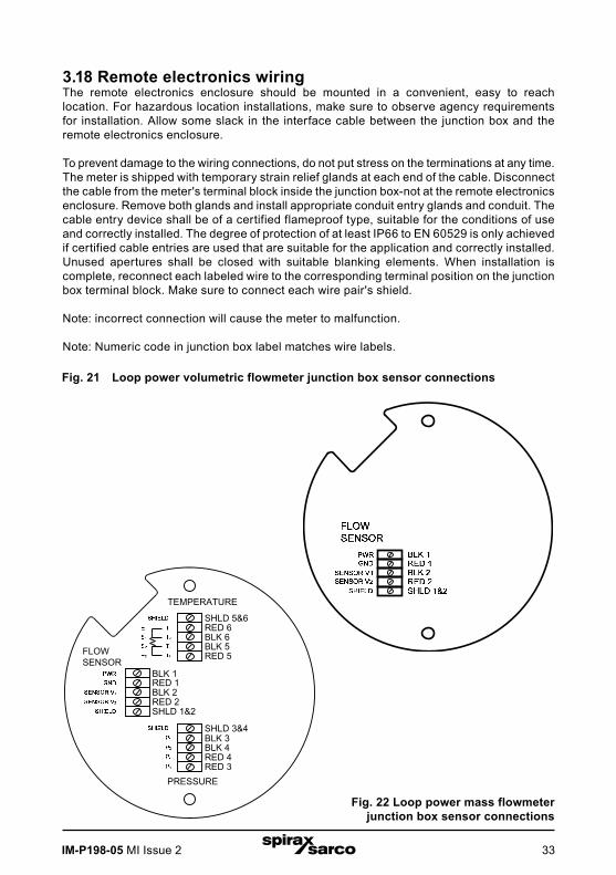
3.18 Remote electronics wiringThe remote electronics enclosure should be mounted in a convenient, easy to reach location. For hazardous location installations, make sure to observe agency requirements for installation. Allow some slack in the interface cable between the junction box and the remote electronics enclosure.
To prevent damage to the wiring connections, do not put stress on the terminations at any time.The meter is shipped with temporary strain relief glands at each end of the cable. Disconnect the cable from the meter's terminal block inside the junction box-not at the remote electronics enclosure. Remove both glands and install appropriate conduit entry glands and conduit. The cable entry device shall be of a certified flameproof type, suitable for the conditions of use and correctly installed. The degree of protection of at least IP66 to EN 60529 is only achieved if certified cable entries are used that are suitable for the application and correctly installed. Unused apertures shall be closed with suitable blanking elements. When installation is complete, reconnect each labeled wire to the corresponding terminal position on the junction box terminal block. Make sure to connect each wire pair's shield.
Note: incorrect connection will cause the meter to malfunction.
Note: Numeric code in junction box label matches wire labels.
PRESSURE
TEMPERATURE
RED 2SHLD 1&2
BLK 2
FLOW SENSOR
BLK 1RED 1
SHLD 3&4
SHLD 5&6RED 6BLK 6BLK 5RED 5
BLK 3BLK 4RED 4RED 3
Fig. 22 Loop power mass flowmeter junction box sensor connections
Fig. 21 Loop power volumetric flowmeter junction box sensor connections

IM-P198-05 MI Issue 234
3.19 High power flowmeter wiring connections
Warning!To avoid potential electric shock, follow National Electric Code safety practices or your local code when wiring this unit to a power source and to peripheral devices. Failure to do so could result in injury or death. All ac power connections must be in accordance with published CE directives. All wiring procedures must be performed with the power off.
The NEMA 4X enclosure contains an integral wiring compartment located in the smaller end of the enclosure. Two ¾" female NPT conduit entries are available for separate power and signal wiring. For all hazardous area installations, make sure to use an agency-approved fitting at each conduit entry. The cable entry device shall be of a certified flameproof type, suitable for the conditions of use and correctly installed. The degree of protection of at least IP66 to EN 60529 is only achieved if certified cable entries are used that are suitable for the application and correctly installed.
Unused apertures shall be closed with suitable blanking elements.
If conduit seals are used, they must be installed within 457 mm (18") of the enclosure.

IM-P198-05 MI Issue 2 35
3.20 Input power connections
Caution!The ac wire insulation temperature rating must meet or exceed 85 °C (185 °F).
To access the wiring terminal blocks, locate and loosen the small set screw which locks the small enclosure cover in place. Unscrew the cover to expose the terminal block.
3.20.1 ac power wiringThe ac power wire size must be 20 to 10 AWG with the wire stripped 7 mm (¼").
The wire insulation temperature must meet or exceed 85 °C (185 °F).
Connect 100 to 240 Vac (5 W maximum) to the Hot and Neutral terminals on the terminal block.
Connect the ground wire to the safety ground lug ( ).
Torque all connections to 0.5 to 0.6 N-m (4.43 to 5.31 in-lbs).
Use a separate conduit entry for signal lines to reduce the possibility of ac noise interference.
Fig. 24 ac power connections
Fig. 23 ac wiring terminals
ac ground
ac phase
ac neutral
Hot
Neut
100 to 240 Vac @ 5 mA maximum
Chassis screw safety ground must be used for proper
installation
IM-P198-05 MI Issue 236
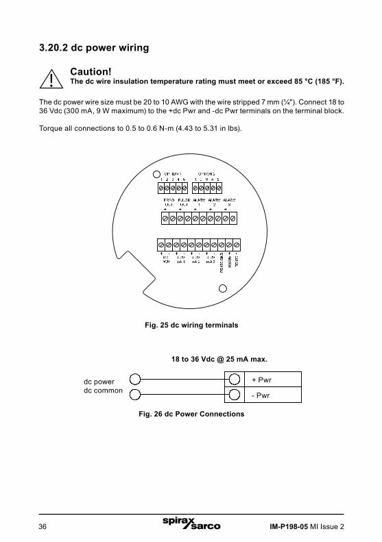
3.20.2 dc power wiring
Caution!The dc wire insulation temperature rating must meet or exceed 85 °C (185 °F).
The dc power wire size must be 20 to 10 AWG with the wire stripped 7 mm (¼"). Connect 18 to 36 Vdc (300 mA, 9 W maximum) to the +dc Pwr and -dc Pwr terminals on the terminal block.
Torque all connections to 0.5 to 0.6 N-m (4.43 to 5.31 in lbs).
Fig. 26 dc Power Connections
Fig. 25 dc wiring terminals
18 to 36 VDC @ 300 mA Max.
DC power
DC common
+ Pwr
- Pwr
18 to 36 Vdc @ 25 mA max.
dc power dc common
+ Pwr
- Pwr

IM-P198-05 MI Issue 2 37
3.21 4-20 mA output connectionsThe standard RIM20 flowmeter has a single 4-20 mA loop. Two additional loops are available on the optional communication board. The 4-20 mA loop current is controlled by the meter electronics. The electronics must be wired in series with the sense resistor or current meter. The current control electronics require 12 volts at the input terminals to operate correctly.
The maximum loop resistance (load) for the current loop output is dependent upon the supply voltage and is given in Figure 26. The 4-20 mA loop is optically isolated from the flowmeter electronics.
Rload is the total resistance in the loop, including the wiring resistance (Rload = Rwire + Rsense ).
To calculate Rmax, the maximum Rload for the loop, subtract the minimum terminal voltage from the supply voltage and divide by the maximum loop current, 20 mA. Thus:
The maximum resistance Rload = Rmax = (Vsupply - 12V) / 0.020 A
Rlo
ad (o
hmns
)
VSupply (volts)
Operating range
Fig. 27 Load resistance versus Input voltage
VSupply (volts)
Rlo
ad (o
hmns
)
+V
4-20 mA +
4-20 mA -
4-20 mA voltage = +V
For Hart communications signal loop must have a minimum of 250 ohms load resistance RL
mA meter
ac and dc powered flowmeters
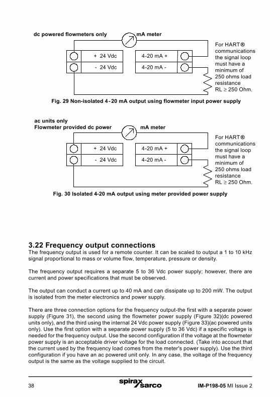
Fig. 28 Isolated 4 - 20 mA output with external power supply
For HART ® communications the signal loop must have a minimum of 250 ohms load resistance RL.
4-20 mA +
4-20 mA -
mA meter
4-20 mA voltage = +V
IM-P198-05 MI Issue 238
Fig. 30 Isolated 4-20 mA output using meter provided power supply
3.22 Frequency output connectionsThe frequency output is used for a remote counter. It can be scaled to output a 1 to 10 kHz signal proportional to mass or volume flow, temperature, pressure or density.
The frequency output requires a separate 5 to 36 Vdc power supply; however, there are current and power specifications that must be observed.
The output can conduct a current up to 40 mA and can dissipate up to 200 mW. The output is isolated from the meter electronics and power supply.
There are three connection options for the frequency output-the first with a separate power supply (Figure 31), the second using the flowmeter power supply (Figure 32)(dc powered units only), and the third using the internal 24 Vdc power supply (Figure 33)(ac powered units only). Use the first option with a separate power supply (5 to 36 Vdc) if a specific voltage is needed for the frequency output. Use the second configuration if the voltage at the flowmeter power supply is an acceptable driver voltage for the load connected. (Take into account that the current used by the frequency load comes from the meter's power supply). Use the third configuration if you have an ac powered unit only. In any case, the voltage of the frequency output is the same as the voltage supplied to the circuit.
mA meterFor HARTcommunicationsthe signal loopmust have aminimum of 250 ohms loadresistance.
RL 250 Ohm
4-20 mA +
4-20 mA -
+ 24 Vdc
- 24 Vdc
mA meterFor HARTcommunicationsthe signal loopmust have aminimum of 250 ohms loadresistance.
RL 250 Ohm
4-20 mA +
4-20 mA -
+ 24 Vdc
- 24 Vdc
dc powered flowmeters only
Fig. 29 Non-isolated 4 - 20 mA output using flowmeter input power supply
ac units onlyFlowmeter provided dc power
For HART ® communications the signal loop must have a minimum of 250 ohms load resistanceRL ³ 250 Ohm.
For HART ® communications the signal loop must have a minimum of 250 ohms load resistanceRL ³ 250 Ohm.
IM-P198-05 MI Issue 2 39
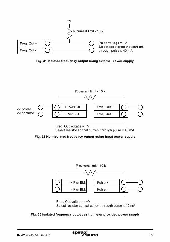
R current limit - 10 k
DC power
DC common
Freq. Out +
Freq. Out -
+ Pwr Bklt
- Pwr Bklt
Freq. Out voltage = +VSelect resistor so that current through pulse 40 mA
Fig. 32 Non-Isolated frequency output using input power supply
Fig. 31 Isolated frequency output using external power supply
+V
R current limit - 10 k
Freq. Out +
Freq. Out -
Pulse voltage = +VSelect resistor so that current through pulse 40 mA
dc power dc common
R current limit - 10 k
Freq. Out +
Freq. Out -
+ 24 Vdc Out
- 24 Vdc Out
Freq. Out voltage = +VSelect resistor so that current through pulse 40 mA
Fig. 33 Isolated frequency output using meter provided power supply
Freq. Out +
Freq. Out -
R current limit - 10 k
Pulse voltage = +VSelect resistor so that current through pulse 40 mA
Freq. Out +
Freq. Out -
Freq. Out voltage = +VSelect resistor so that current through pulse 40 mA
+ Pwr Bklt
- Pwr Bklt
R current limit - 10 k
Pulse +
Pulse -
+ Pwr Bklt
- Pwr Bklt
Freq. Out voltage = +VSelect resistor so that current through pulse 40 mA
R current limit - 10 k

IM-P198-05 MI Issue 240
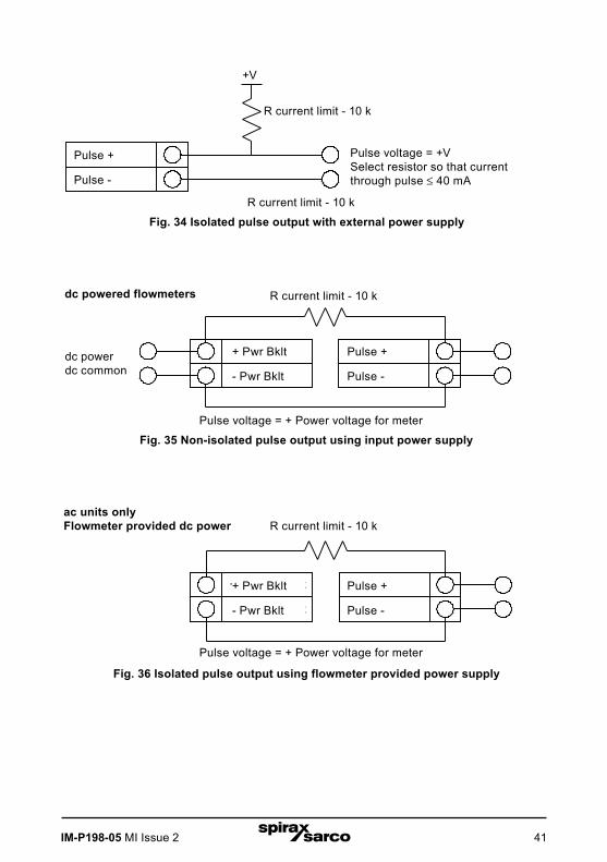
3.23 Pulse output connectionsThe pulse output is used for a remote counter. When the preset volume or mass (defined in the totalizer settings, see Section 4) has passed the meter, the output provides a 50 millisecond square pulse.
The pulse output optical relay is a normally-open single-pole relay. The relay has a nominal 200 volt/160 ohm rating. This means that it has a nominal on-resistance of 160 ohms, and the largest voltage that it can withstand across the output terminals is 200 volts. However, there are current and power specifications that must be observed. The relay can conduct a current up to 40 mA and can dissipate up to 320 mW. The relay output is isolated from the meter electronics and power supply.
There are three connection options for the pulse output-the first with a separate power supply (Figure 34), the second using the flowmeter power supply (Figure 35)(dc powered units only), and the third using the internal 24 Vdc power supply (Figure 36)(ac powered units only). Use the first option with a separate power supply (5 to 36 Vdc) if a specific voltage is needed for the pulse output. Use the second configuration if the voltage at the flowmeter power supply is an acceptable driver voltage for the load connected. (Take into account that the current used by the pulse load comesfrom the meter's power supply). Use the third configuration if you have an ac powered unit only. In any case, the voltage of the pulse output is the same as the voltage supplied to the circuit.
IM-P198-05 MI Issue 2 41
R current limit - 10K
Pulse +
Pulse -
+ 24 Vdc Out
- 24 Vdc Out
Pulse voltage = + Power voltage for meter
+V
R current limit - 10K
Pulse +
Pulse -
Pulse voltage = +VSelect resistor so that current through pulse 40 mA
R current limit - 10K
Fig. 36 Isolated pulse output using flowmeter provided power supply
Fig. 35 Non-isolated pulse output using input power supply
ac units onlyFlowmeter provided dc power
R current limit - 10K
DC power
DC common
Pulse +
Pulse -
+ Pwr Bklt
- Pwr Bklt
Pulse voltage = + Power voltage for meter
Fig. 34 Isolated pulse output with external power supply
dc powered flowmeters
dc power dc common
Pulse +
Pulse -
R current limit - 10 k
Pulse voltage = +VSelect resistor so that current through pulse 40 mA
Pulse +
Pulse -
Pulse voltage = + Power voltage for meter
+ Pwr Bklt
- Pwr Bklt
R current limit - 10 k
R current limit - 10 k
Pulse +
Pulse -
Pulse voltage = + Power voltage for meter
+ Pwr Bklt
- Pwr Bklt
R current limit - 10 k

IM-P198-05 MI Issue 242
3.24 Alarm output connectionsOne alarm output (Alarm 1) is included on the standard RIM20 flowmeter. Two or more alarms (Alarm 2 and Alarm 3) are included on the optional communication board. The alarm output optical relays are normally- open single-pole relays. The relays have a nominal 200 volt/160ohm rating. This means that each relay has a nominal on-resistance of 160 ohms and the largest voltage that it can withstand across the output terminals is 200 volts. However, there are current and power specifications that must be observed. The relay can conduct a current up to 40 mA and can dissipate up to 320 mW. The relay output is isolated from the meter electronics and power supply. When the alarm relay is closed, the current draw will be constant. Make sure to size Rload appropriately.
There are three connection options for the alarm output-the first with a separate power supply (Figure 37), the second using the flowmeter power supply (Figure 38)(dc powered units only) and the third with the meter provided power supply (Figure 39)(ac powered units only). Use the first option with a separate power supply (5 to 36 Vdc) if a specific voltage is needed for the alarm output. Use the second configuration if the voltage at the flowmeter power supply is an acceptable driver voltage for the load connected. (Take into account that the current used by the alarm load comes from the meter's power supply). Use the third if you have an ac powered unit only. In any case, the voltage of the alarm output is the same as the voltage supplied to the circuit.
The alarm output is used for transmitting high or low process conditions as defined in the alarm settings (see Section 4).

IM-P198-05 MI Issue 2 43
+V
R current limit - 10K
Alarm +
Alarm -
Pulse voltage = +VSelect resistor so that current through pulse 40 mA
R current limit - 10K
R current limit - 10K
DC power
DC common
Alarm +
Alarm -
+ Pwr
- Pwr
Alarm voltage = + Power voltage for meter
Fig. 39 Isolated pulse output using flowmeter provided power supply
Fig. 38 Non-isolated pulse output using input power supply
ac units onlyFlowmeter provided dc power
Fig. 37 Isolated pulse output with external power supply
dc powered flowmeters
dc power dc common
R current limit - 10K
Alarm +
Alarm -
+ 24 Vdc Out
- 24 Vdc Out
Alarm voltage = + Power voltage for meter
Alarm +
Alarm -
R current limit - 10 k
Pulse voltage = +VSelect resistor so that current through pulse 40 mA
Alarm +
Alarm -
Alarm voltage = + Power voltage for meter
+ Pwr
- Pwr
R current limit - 10 k
R current limit - 10 k
Alarm +
Alarm -
Alarm voltage = + Power voltage for meter
+ 24 Vdc Out
- 24 Vdc Out
R current limit - 10 k
IM-P198-05 MI Issue 244
Fig. 41
Option 1
1 2 3 4 5
Option 2
1 2 3 4 5
PRESSURE
TEMPERATURE
RED 2SHLD 1&2
BLK 2
VORTEX
BLK 1RED 1
SHLD 3&4
SHLD 5&6RED 6BLK 6BLK 5RED 5
BLK 3BLK 4RED 4RED 3
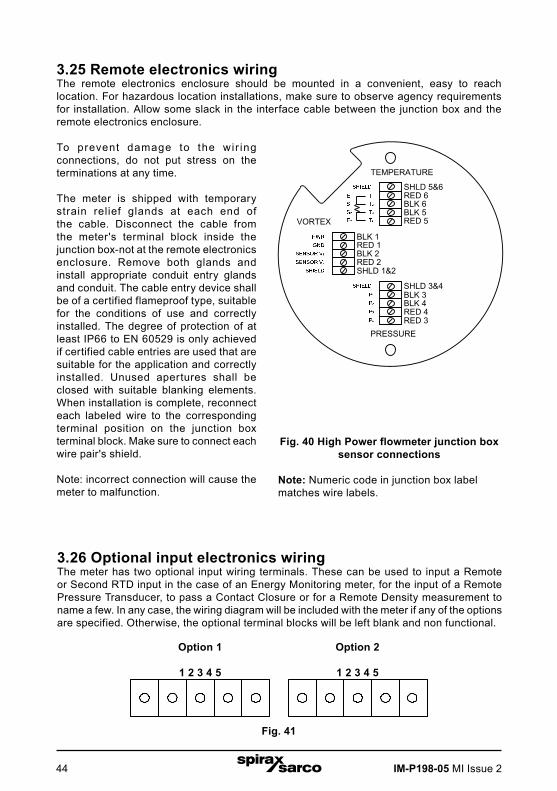
3.25 Remote electronics wiringThe remote electronics enclosure should be mounted in a convenient, easy to reach location. For hazardous location installations, make sure to observe agency requirements for installation. Allow some slack in the interface cable between the junction box and the remote electronics enclosure.
To prevent damage to the wir ing connections, do not put stress on the terminations at any time.
The meter is shipped with temporary strain relief glands at each end of the cable. Disconnect the cable from the meter's terminal block inside the junction box-not at the remote electronics enclosure. Remove both glands and install appropriate conduit entry glands and conduit. The cable entry device shall be of a certified flameproof type, suitable for the conditions of use and correctly installed. The degree of protection of at least IP66 to EN 60529 is only achieved if certified cable entries are used that are suitable for the application and correctly installed. Unused apertures shall be closed with suitable blanking elements. When installation is complete, reconnect each labeled wire to the corresponding terminal position on the junction box terminal block. Make sure to connect each wire pair's shield.
Note: incorrect connection will cause the meter to malfunction.
Fig. 40 High Power flowmeter junction box sensor connections
Note: Numeric code in junction box label matches wire labels.
3.26 Optional input electronics wiringThe meter has two optional input wiring terminals. These can be used to input a Remote or Second RTD input in the case of an Energy Monitoring meter, for the input of a Remote Pressure Transducer, to pass a Contact Closure or for a Remote Density measurement to name a few. In any case, the wiring diagram will be included with the meter if any of the optionsare specified. Otherwise, the optional terminal blocks will be left blank and non functional.
IM-P198-05 MI Issue 2 45
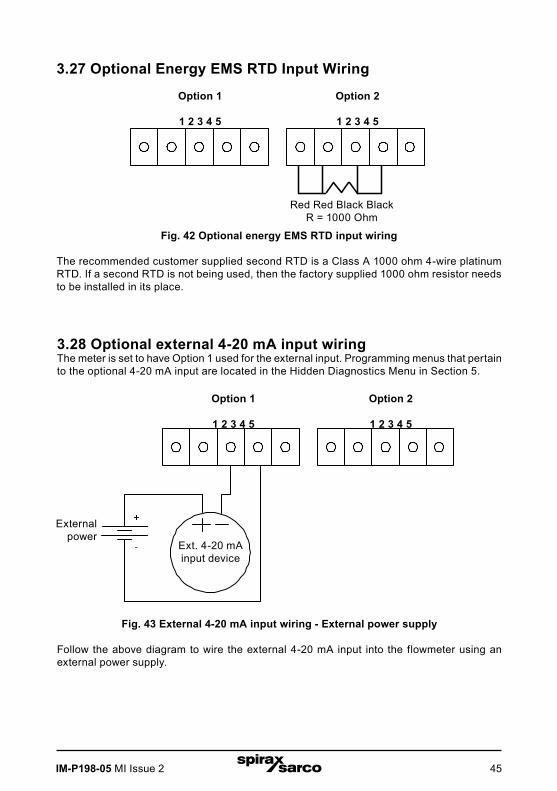
3.27 Optional Energy EMS RTD Input Wiring
Option 1
1 2 3 4 5
Option 2
1 2 3 4 5
Red Red Black BlackR = 1000 Ohm
Fig. 42 Optional energy EMS RTD input wiring
The recommended customer supplied second RTD is a Class A 1000 ohm 4-wire platinum RTD. If a second RTD is not being used, then the factory supplied 1000 ohm resistor needs to be installed in its place.
3.28 Optional external 4-20 mA input wiringThe meter is set to have Option 1 used for the external input. Programming menus that pertain to the optional 4-20 mA input are located in the Hidden Diagnostics Menu in Section 5.
Option 2Option 11 2 ! " # $ % ! " #
Ext. 4 20 mAInput Device
+ Dc PWR
Dc PWRDc power
Dc common
Dc powered meter only.
Fig. 43 External 4-20 mA input wiring - External power supply
Follow the above diagram to wire the external 4-20 mA input into the flowmeter using an external power supply.
Option 1
1 2 3 4 5
Option 2
1 2 3 4 5
External power
Ext. 4-20 mAinput device
IM-P198-05 MI Issue 246
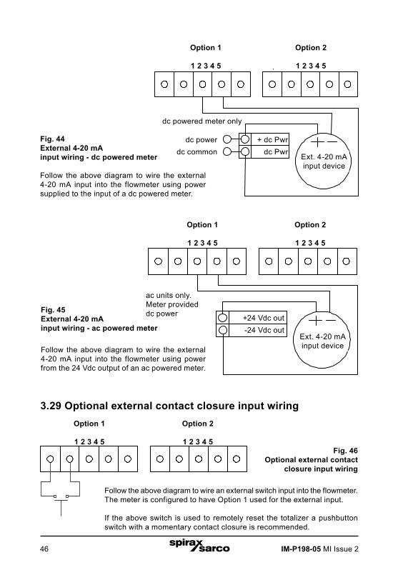
Fig. 44 External 4-20 mA input wiring - dc powered meter
Follow the above diagram to wire the external 4-20 mA input into the flowmeter using power supplied to the input of a dc powered meter.
Option 2Option 11 2 ! " # $ % ! " #
Ext. 4 20 mAInput Device
+ d c PWR
d c PWRdc power
dc common
d c powered meter only.
Fig. 46 Optional external contact
closure input wiring
Follow the above diagram to wire an external switch input into the flowmeter. The meter is configured to have Option 1 used for the external input.
If the above switch is used to remotely reset the totalizer a pushbutton switch with a momentary contact closure is recommended.
Ac units only.Meter provided Dc power
Ac units only.Meter provided Dc powerFig. 45
External 4-20 mA input wiring - ac powered meter
Follow the above diagram to wire the external 4-20 mA input into the flowmeter using power from the 24 Vdc output of an ac powered meter.
Option 1
1 2 3 4 5
Option 2
1 2 3 4 5
Option 1
1 2 3 4 5
Option 2
1 2 3 4 5
Option 1
1 2 3 4 5
Option 2
1 2 3 4 5
3.29 Optional external contact closure input wiring
ac units only.Meter provideddc power
Ext. 4-20 mAinput device
Ext. 4-20 mAinput device
+ dc Pwr dc Pwr
dc powerdc common
dc powered meter only
+24 Vdc out-24 Vdc out

IM-P198-05 MI Issue 2 47
4. Operating instructionsAfter installing the RIM20 rotor insertion flowmeter, you are ready to begin operation. The sections in this Section explain the display/keypad commands, meter start-up and programming.
The meter is ready to operate at start up without any special programming.
To enter parameters and system settings unique to your operation, see the following pages for instructions on using the setup menus.
4.1 Flowmeter display/keypadThe flowmeter’s digital electronics allow you to set, adjust and monitor system parameters and performance. A full range of commands are available through the display/keypad. The LCD display gives 2 x 16 characters for flow monitoring and programming.
The six push-buttons can be operated with the enclosure cover removed. Or, the explosion-proof cover can remain in place and the keypad operated with a hand-held magnet positioned at the side of the enclosure as shown in Figure 47.
Fig. 47 Display / keypad commands
From the Run mode, the ENTER key allows access to the Setup Menus (through a password screen). Within the Setup Menus, pressing ENTER activates the current field.
To set new parameters, press the ENTER keyuntil an underline cursor appears.
Use the keys to select new parameters.
Press ENTER to continue. (If change is not allowed, ENTER has no effect.) All outputs are disabled when using the Setup Menus.
The EXIT key is active within the Setup Menus.When using a Setup Menu, EXIT returns you to the Run mode. If you are changing a parameter and make a mistake, EXIT allows you to start over.
The keys advance through each screen of the current menu. When changing a system parameter, all keys are available to enter new parameters.
RIM20
Hand-held magnet

IM-P198-05 MI Issue 248
4.2 Start-up
NoteStarting the flowmeter or pressing EXIT will always display the Run mode screens.
To begin flowmeter operation:
1. Verify the flowmeter is installed and wired as described in Section 3.
2. Apply power to the meter. At start up, the unit runs a series of selftests that check the RAM, ROM, EPROM and all flow sensing components.
After completing the self-test sequence, the Run mode screens appear.
3. The Run mode displays flow information as determined by system settings. Some screens depicted on the next page may not be displayed based on these settings. Press the arrow keys to view the Run mode screens.
4. Press the ENTER key from any Run mode screen to access the Setup Menus. Use the Setup Menus to configure the meter’s multiparameter features to fit your application.

IM-P198-05 MI Issue 2 49
Run mode screens
Press Exit to return to Run mode
Use keys to access each item

IM-P198-05 MI Issue 250
4.3 Using the set-up menus
Run mode screens

IM-P198-05 MI Issue 2 51
Setup menus
Energy EM meters only
4.4 Programming the flowmeter1. Enter the Setup Menu by pressing the ENTER key until prompted for a password. (All
outputs are disabled while using the Setup Menus.)
2. Use the ñòïð keys to select the password characters (1234 is the factory-set password). When the password is correctly displayed, press ENTER to continue.
3. Use the Setup Menus described on the following pages to customize the multiparameter features of your RIM20 flowmeter. (The entire lower display line is available for entering parameters.) Some items depicted in the graphic on the preceding page may not be displayed based on flowmeter configuration settings
4. To activate a parameter, press ENTER. Use the ñòïð keys to make selections. Press ENTER to continue. Press EXIT to save or discard changes and return to Run mode.
5. Program the UNITS menu first because later menus will be based on the units selected.

IM-P198-05 MI Issue 252
4.5 Output menu

IM-P198-05 MI Issue 2 53
Example for setting an outputThe following shows how to set Output 1 to measure mass flow with 4 mA = 0 lb/hr and 20 mA = 100 lb/hr with a time constant of 5 seconds. (All outputs are disabled while using the Setup Menus.)
First, set the desired units of measurement:
1. Use ñòïð keys to move to the Units Menu.
2. Press key until Mass Flow Unit appears. Press ENTER.
3. Press key until lb appears in the numerator. Press ð key to move the underline cursor to the denominator. Press the key until hr appears in the denominator. Press ENTER to select.
4. Press key until Units Menu appears.
Second, set the Analogue output:
1. Use ñòïð keys to move to the Output Menu.
2. Press the key until 4-20 mA Output 1 appears.
3. Press ð key to access Measure selections. Press ENTER and press the key to select Mass. Press ENTER.
4. Press ð key to set the 4 mA point in the units you have selected for mass of lb/hr. Press ENTER and use ñòïð keys to set 0 or 0.0. Press ENTER.
5. Press ð key to set the 20 mA point. Press ENTER and use ñòïð keys to set 100 or 100.0. Press ENTER.
6. Press ð key to select the Time Constant. Press ENTER and use ñòïð keys to select 5. Press ENTER.
7. Press the EXIT key and answer YES to permanently save your changes.

IM-P198-05 MI Issue 254
4.6 Display menu
Use the Display Menu to set the cycle time for automatic screen sequencing used in the Run Mode, change the precision of displayed values, smooth the values or enable or disable each item displayed in the Run mode screens.
Password
DisplayMenu
Cycle Time (sec)0
Number of Digits2
Display TC (sec)1
MF Vf Te Pr De T Y or N
A1 A2 A3 Fl Dt EY or N
ENTER
ENTER
Run Mode
Usekeys to access menus
If Cycle Time is set to zero, manual advance is required
Used to set the number of digits displayed after the decimal point
TC = Display Time constant, used to smooth display
MF = Mass FlowVf = Volume FlowTe = TemperaturePr = PressureDe = DensityT = Total
A1 = Alarm 1 StatusA2 = Alarm 2 StatusA3 = Alarm 3 StatusFl = FluidDt = Density
* E = Energy
For each parameter:Select Yes to view parameter in Run ModeSelect No to hide parameter in Run Mode
* Energy EM Meters Only

IM-P198-05 MI Issue 2 55
Example for changing a run mode display itemThe following shows how to remove the temperature screen from the Run mode screens. Note: all outputs are disabled while using the Setup Menus.
1. Use ïð keys to move to the Display Menu.
2. Press ò key until Mf Vf Pr Te De T appears.
3. Press ENTER to select. Press ð key until the cursor is positioned below Te.
4. Press ò key until N appears. Press ENTER to select.
5. Press EXIT and then ENTER to save changes and return to the Run mode.

IM-P198-05 MI Issue 256
4.7 Alarms menu
Energy EM meters only
IM-P198-05 MI Issue 2 57
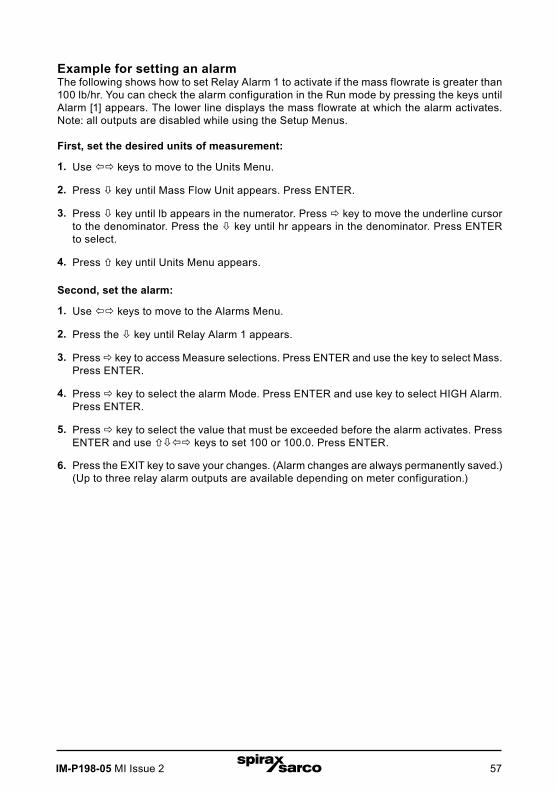
Example for setting an alarmThe following shows how to set Relay Alarm 1 to activate if the mass flowrate is greater than 100 lb/hr. You can check the alarm configuration in the Run mode by pressing the keys until Alarm [1] appears. The lower line displays the mass flowrate at which the alarm activates. Note: all outputs are disabled while using the Setup Menus.
First, set the desired units of measurement:
1. Use ïð keys to move to the Units Menu.
2. Press ò key until Mass Flow Unit appears. Press ENTER.
3. Press ò key until lb appears in the numerator. Press ð key to move the underline cursor to the denominator. Press the ò key until hr appears in the denominator. Press ENTER to select.
4. Press ñ key until Units Menu appears.
Second, set the alarm:
1. Use ïð keys to move to the Alarms Menu.
2. Press the ò key until Relay Alarm 1 appears.
3. Press ð key to access Measure selections. Press ENTER and use the key to select Mass. Press ENTER.
4. Press ð key to select the alarm Mode. Press ENTER and use key to select HIGH Alarm. Press ENTER.
5. Press ð key to select the value that must be exceeded before the alarm activates. Press ENTER and use ñòïð keys to set 100 or 100.0. Press ENTER.
6. Press the EXIT key to save your changes. (Alarm changes are always permanently saved.)(Up to three relay alarm outputs are available depending on meter configuration.)
IM-P198-05 MI Issue 258
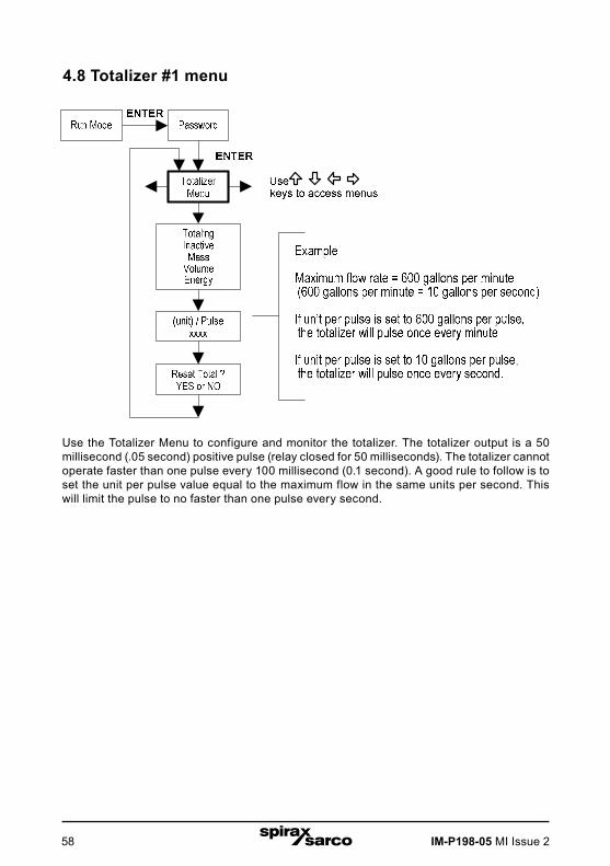
4.8 Totalizer #1 menu
Use the Totalizer Menu to configure and monitor the totalizer. The totalizer output is a 50 millisecond (.05 second) positive pulse (relay closed for 50 milliseconds). The totalizer cannot operate faster than one pulse every 100 millisecond (0.1 second). A good rule to follow is to set the unit per pulse value equal to the maximum flow in the same units per second. This will limit the pulse to no faster than one pulse every second.

IM-P198-05 MI Issue 2 59
Example for setting an alarmThe following shows how to set the totalizer to track mass flow in kg/sec. (All outputs are disabled while using the Setup Menus.)
First, set the desired units of measurement:
1. Use ïð keys to move to the Units Menu.
2. Press ò key until Mass Flow Unit appears. Press ENTER.
3. Press ò key until kg appears in the numerator. Press ò key to move the underline cursor to the denominator. Press the ò key until sec appears in the denominator. Press ENTER to select.
4. Press ñ key until Units Menu appears.
Second, set the pulse output:
1. Use ïð keys to move to the Totalizer Menu.
2. Press the ò key until Totaling appears.
3. Press ENTER and press the ò key to select Mass. Press ENTER.
4. Press ò key to set the pulse output in the units you have selected for mass flow of kg/sec. Press ENTER and use ñòïð keys to set the pulse value equal to the maximum flow in the same units per second. Press ENTER.
5. To reset the totalizer, press ò key until Reset Total? appears. Press ENTER and the key to reset the totalizer if desired. Press ENTER.
6. Press the EXIT key and answer YES to permanently save your changes.

IM-P198-05 MI Issue 260
4.9 Totalizer #2 menu
Use the Totalizer #2 to Monitor Flow or Energy. Note that Totalizer #2 does not operate a relay, it is for monitoring only.
Use the Totalizer #2 to Monitor Flow or Energy. Note that Totalizer #2 does not operate a relay, it is
for monitoring only.
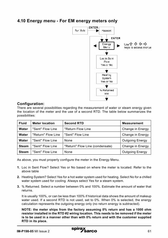
IM-P198-05 MI Issue 2 61
4.10 Energy menu - For EM energy meters only
Configuration:There are several possibilities regarding the measurement of water or steam energy given the location of the meter and the use of a second RTD. The table below summarizes the possibilities:
Fluid Meter location Second RTD Measurement
Water "Sent" Flow Line "Return Flow Line Change in Energy
Water "Return" Flow Line "Sent" Flow Line Change in Energy
Water "Sent" Flow Line None Outgoing Energy
Steam "Sent" Flow Line "Return" Flow Line (condensate) Change in Energy
Steam "Sent" Flow Line None Outgoing Energy
As above, you must properly configure the meter in the Energy Menu.
1. Loc in Sent Flow? Select Yes or No based on where the meter is located. Refer to the above table
2. Heating System? Select Yes for a hot water system used for heating. Select No for a chilled water system used for cooling. Always select Yes for a steam system.
3. % Returned. Select a number between 0% and 100%. Estimate the amount of water that returns.
It is usually 100%, or can be less than 100% if historical data shows the amount of makeup water used. If a second RTD is not used, set to 0%. When 0% is selected, the energy calculation represents the outgoing energy only (no return energy is subtracted).
NOTE: the meter ships from the factory assuming 0% return and has a 1000 ohm resistor installed in the RTD #2 wiring location. This needs to be removed if the meter is to be used in a manner other than with 0% return and with the customer supplied RTD in its place.
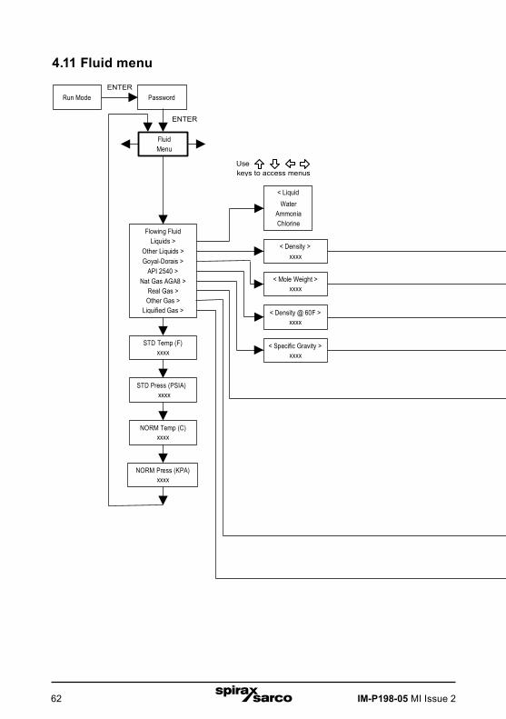
IM-P198-05 MI Issue 262
4.11 Fluid menu
PasswordRun ModeENTER
< LiquidWater
AmmoniaChlorine
< Density >xxxx
< AL >xxxx
< BLxxxx
< BLxxxx
Select “Steam T & P Comp” for VT andVTP models. The VT model will display“Sat Steam T Comp” for the fluid typein the run mode screens.
For a V model in any fluid, enter nominal operating temperature andpressure as simulated values in the diagnostics menu.
< Viscosityxxxx
< Liquified GasCarbon Dioxide
NitrogenHydrogenOxygenArgon
Nitrous Oxide
Fluid Menu
< Real GasSteam T & P Comp
AirArgon
Ammonia CO
CO2Helium
HydrogenMethaneNitrogenOxygenPropane
< Specific Gravity >xxxx
< K0 >xxxx
< K1 >xxxx
< AL >xxxx
< Compress (Z) >xxxx
ENTER
Usekeys to access menus
Flowing FluidLiquids >
Other Liquids >Goyal-Dorais >
API 2540 >Nat Gas AGA8 >
Real Gas >Other Gas >
Liquified Gas >
< Mole Weight >xxxx
< CRIT PRESS >xxxx
< CRIT TEMP >xxxx
< CRIT Z >xxxx
< AL >xxxx
< BLxxxx
< Density @ 60F >xxxx
STD Temp (F)xxxx
< Specific Gravity >xxxx
< MoleFract N2 >xxxx
<MoleFract CO2>xxxx
<Ref Temp(F)>xxxx
< Ref Press(PSIA)xxxx
STD Press (PSIA)xxxx
NORM Temp (C)xxxx
NORM Press (KPA)xxxx
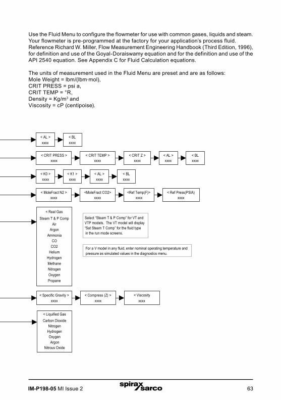
IM-P198-05 MI Issue 2 63
PasswordRun ModeENTER
< LiquidWater
AmmoniaChlorine
< Density >xxxx
< AL >xxxx
< BLxxxx
< BLxxxx
Select “Steam T & P Comp” for VT andVTP models. The VT model will display“Sat Steam T Comp” for the fluid typein the run mode screens.
For a V model in any fluid, enter nominal operating temperature andpressure as simulated values in the diagnostics menu.
< Viscosityxxxx
< Liquified GasCarbon Dioxide
NitrogenHydrogenOxygenArgon
Nitrous Oxide
Fluid Menu
< Real GasSteam T & P Comp
AirArgon
Ammonia CO
CO2Helium
HydrogenMethaneNitrogenOxygenPropane
< Specific Gravity >xxxx
< K0 >xxxx
< K1 >xxxx
< AL >xxxx
< Compress (Z) >xxxx
ENTER
Usekeys to access menus
Flowing FluidLiquids >
Other Liquids >Goyal-Dorais >
API 2540 >Nat Gas AGA8 >
Real Gas >Other Gas >
Liquified Gas >
< Mole Weight >xxxx
< CRIT PRESS >xxxx
< CRIT TEMP >xxxx
< CRIT Z >xxxx
< AL >xxxx
< BLxxxx
< Density @ 60F >xxxx
STD Temp (F)xxxx
< Specific Gravity >xxxx
< MoleFract N2 >xxxx
<MoleFract CO2>xxxx
<Ref Temp(F)>xxxx
< Ref Press(PSIA)xxxx
STD Press (PSIA)xxxx
NORM Temp (C)xxxx
NORM Press (KPA)xxxx
Use the Fluid Menu to configure the flowmeter for use with common gases, liquids and steam. Your flowmeter is pre-programmed at the factory for your application’s process fluid.Reference Richard W. Miller, Flow Measurement Engineering Handbook (Third Edition, 1996), for definition and use of the Goyal-Doraiswamy equation and for the definition and use of the API 2540 equation. See Appendix C for Fluid Calculation equations.
The units of measurement used in the Fluid Menu are preset and are as follows:Mole Weight = lbm/(lbm·mol), CRIT PRESS = psi a, CRIT TEMP = °R, Density = Kg/m3 andViscosity = cP (centipoise).
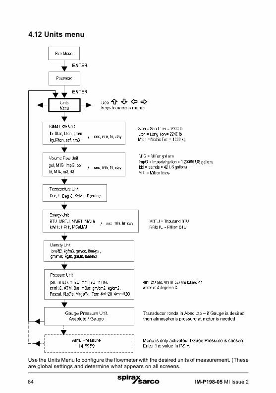
IM-P198-05 MI Issue 264
4.12 Units menu
Use the Units Menu to configure the flowmeter with the desired units of measurement. (Theseare global settings and determine what appears on all screens.

IM-P198-05 MI Issue 2 65
4.13 Time and date menu
Use the Time and Date Menu to enter the correct time and date into the flowmeter’s memory. The parameters are used in the Run mode and the alarm and system log files.
Note: Time is displayed in AM/PM format, but military format is used to set the time.For example, 1:00 PM is entered as 13:00:00 in the Set Time menu.
Example for setting the timeHow to set the time to 12:00:00. You can check the time in the Run mode by pressing the keys until the Time & Date screen appears. Note: all outputs are disabled while using the Setup Menus.
1. Use ïð keys to move to the Time and Date Menu.
2. Press key until Set Time appears. Press ENTER.
3. Press ò key until 1 appears. Press ð key to move the underline cursor to the next digit.Press the ò key until 2 appears. Continue sequence until all desired parameters are entered.Press ENTER to return to the Time and Date Menu.
4. Press EXIT to return to the Run mode.
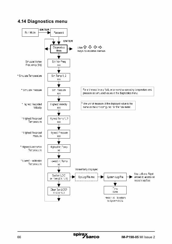
IM-P198-05 MI Issue 266
4.14 Diagnostics menu

IM-P198-05 MI Issue 2 67
Use the Diagnostics Menu to simulate operation and review the system files. The system log files contain time/date stamped messages including: power on, power off, programming time outs, parameter faults, incorrect password entry and other various information relative to system operation and programming.
The simulated inputs are for testing the meter to verify that the programming is correct. They are also used to enter nominal operating temperature and pressure for the V only model. Simulated turbine frequency allows you to enter any value for the sensor input in Hz. The meter will calculate a flowrate based on the corresponding value and update all Analogue outputs (the totalizer display and output is not affected by a simulated frequency). The simulated pressureand temperature settings work the same way. The meter will output these new values and will use them to calculate a new density for mass flow measurement. Note: when your diagnostic work is complete, make sure to return the values to zero to allow the electronics to use the actual transducer values. For the V only model keep the temperature and pressure at nominal operating conditions.
If the meter display indicates a temperature or pressure fault, a substitute value can be entered to allow flow calculations to continue at a fixed value until the source of the fault is identified and corrected. The units of measure of the displayed values are the same as the units configured for the flowmeter.

IM-P198-05 MI Issue 268
4.15 Calibration menu
The Calibration menu contains the calibration coefficients for the flowmeter. These values should by changed only by properly trained personnel. The Low Flow Cutoff is set at the factory.
Consult the factory for help with these settings if the meter is showing erratic flowrate.
Run Mode
Meter Factorxxxx
Password
CalibrationMenu
Pipe IDxx.xxxx
Low Flow Cutoffxx
< Vol (xxx/xxx) >xxx
Serial Numberxxxxxxxxx
ENTER
ENTER
Usekeys to access menus
Low Flow Cutoffsetting displayedin volumetric flowunits (view only)
< Mass (xxx/xxx) >xxx
Low Flow Cutoffsetting displayed
in mass flowunits (view only)

IM-P198-05 MI Issue 2 69
4.16 Password menu
Use the Password Menu to set or change the system password. The factory-set passwordis 1234.

IM-P198-05 MI Issue 270
5. Serial communications5.1 HART communicationsThe HART Communications Protocol (Highway Addressable Remote Transducer Protocol) is a bidirectional digital serial communications protocol. The HART signal is based on the Bell 202 standard and is superimposed on 4-20 mA Output 1. Peer-to-peer (Analogue / digital) and multi-drop (digital only) modes are supported.
Warning!Place controls in manual mode when making configuration changes to the turbine meter.
5.2 WiringThe diagrams below detail the proper connections required for HART communications:
5.2.1 Loop powered meter wiring
Fig. 48 Loop Powered Meter Wiring (HART)
LOO
P
PO
WE
R+
-
FR
EQ
OU
TP
ULS
EO
UT -
-+
+
OP
TIO
NA
L B
AC
KLI
GH
T
PO
WE
R+
- R load,250 ohmminimum
+
_
d cPowerSupply
Remote Connectionfor Communicator
CurrentMeter
Field Connectionfor Communicator
Turbine Meter
Current meter
Turbine meter
R load, 250 ohm minimum
dc power supply
Field connection for communicator
Remote connection for communicator
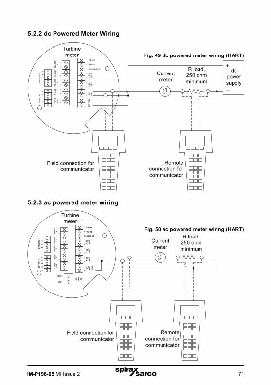
IM-P198-05 MI Issue 2 71
R load,250 ohmminimum
+
_
DCPowerSupply
Remote Connectionfor Communicator
Field Connectionfor Communicator
CurrentMeter
Turbine Meter
4-20
mA
34-
20m
A 1
DC
PW
R+
-+
4-20
mA
2
-+
-+
R S 485
R S 485
R S 485 G ND
-
OP
TIO
N 2
+ALA
RM
2P
ULS
EO
UT
FR
EQ
OU
T+
-+ALA
RM
1-
+-
4
OP
TIO
N 1
12
31
52
3
ALA
RM
3-
+-
45
+
-
R load,250 ohmminimum
Remote Connectionfor Communicator
Field Connectionfor Communicator
CurrentMeter
Turbine Meter
4-20
mA
3
AC
PW
R
IN
4-20
mA
124 VD
C
OU
T
+-
+4-
20m
A 2
-+
-+
R S 485
R S 485
R S 485 G ND
-
OP
TIO
N 2
+ALA
RM
2
HOT
PU
LSE
OU
T
NE UT
FR
EQ
OU
T+
-+ALA
RM
1-
+-
4
OP
TI O
N 1
12
31
52
3
ALA
RM
3-
+-
45
+
-
R load,250 ohmminimum
+
_
d cPowerSupply
Remote Connectionfor Communicator
Field Connectionfor Communicator
CurrentMeter
Turbine Meter
4-20
mA
34-
20m
A 1
DC
PW
R+
-+
4-20
mA
2
-+
-+
R S 485
R S 485
R S 485 G ND
-
OP
TIO
N 2
+ALA
RM
2P
ULS
EO
UT
FR
EQ
OU
T+
-+ALA
RM
1-
+-
4
OP
TIO
N 1
12
31
52
3
ALA
RM
3-
+-
45
+
-
R load,250 ohmminimum
Remote Connectionfor Communicator
Field Connectionfor Communicator
CurrentMeter
Turbine Meter
4-20
mA
3
AC
PW
R
IN
4-20
mA
12 4 VD
C
OU
T
+-
+4-
20m
A 2
-+
-+
R S 485
R S 485
R S 485 G ND
-
OP
TIO
N 2
+ALA
RM
2
HOT
PU
LSE
OU
T
NE UT
FR
EQ
OU
T+
-+ALA
RM
1-
+-
4
OP
TIO
N 1
12
31
52
3
ALA
RM
3-
+-
45
+
-
5.2.2 dc Powered Meter Wiring
5.2.3 ac powered meter wiring
Fig. 50 ac powered meter wiring (HART)
Fig. 49 dc powered meter wiring (HART)
Field connection for communicator
Remote connection for communicator
Turbine meter
Current meter
R load, 250 ohm minimum
Current meter
Turbine meter
R load, 250 ohm minimum
dc power supply
Field connection for communicator
Remote connection for communicator
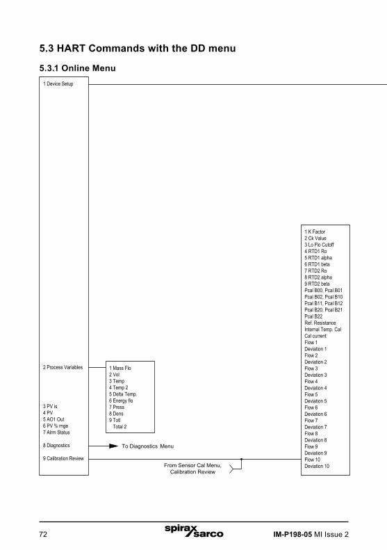
IM-P198-05 MI Issue 272
5.3 HART Commands with the DD menu
5.3.1 Online Menu1 Device Setup
2 Process Variables
3 PV is4 PV5 AO1 Out6 PV % rnge7 Alrm Status
8 Diagnostics
9 Calibration Review
1 Display Unit
2 Analog Output
3 External Loop
4 Meter Display
5 Alarm Setup
6 Totalizer
7 Fluid Menu
8 Energy Setup
9 Device Menu
Diagnostics
Sensor Cal
Review
1 Mass flo unit2 Vol unit3 Temp unit4 Energy flo unit5 Line press unit6 Dens unit7 Totalizer units8 Std & Norm Cond
1 Disp Cycle2 Disp Digits3 Disp Damping4 Init Displ.5 Disp Show/Hide
1 Alarm Status2 Alarm 1 Setup3 Alarm 2 Setup4 Alarm 3 Setup5 Records in Log6 Read Alarm Log7 Alarm Log Clear
1 Total2 Totalize3 Amount/Pulse4 Total 25 Totalize 26 Clear Totalizer
1 Mass Flo2 Vol3 Temp4 Temp 25 Delta Temp.6 Energy flo7 Press8 Dens9 Totl Total 2
1 K Factor2 Ck Value3 Lo Flo Cutoff4 RTD1 Ro5 RTD1 alpha6 RTD1 beta7 RTD2 Ro8 RTD2 alpha9 RTD2 betaPcal B00, Pcal B01Pcal B02, Pcal B10Pcal B11, Pcal B12Pcal B20, Pcal B21Pcal B22Ref. ResistanceInternal Temp. CalCal currentFlow 1Deviation 1Flow 2Deviation 2Flow 3Deviation 3Flow 4Deviation 4Flow 5Deviation 5Flow 6Deviation 6Flow 7Deviation 7Flow 8Deviation 8Flow 9Deviation 9Flow 10Deviation 10
1 Alrm 1 var2 Alrm 1 typ3 Alrm 1 set pt
1 Alrm 2 var2 Alrm 2 typ3 Alrm 2 set pt
1 Alrm 3 var2 Alrm 3 typ3 Alrm 3 set pt
1 Norm Temp2 Norm Press3 Std Temp4 Std Press
1 External Input2 Set Ext. 4 mA3 Set Ext. 20 mA
InactiveTemp1Temp 2Pressure
1 Meter Location2 Heating or Cooling3 % Return
1 Date2 h3 min4 s5 Password6 Meter Size7 Dev id8 Tag9 Descriptor Message Final assy num Poll adr Num req preams Config Code Compile Date Compile Time Signal Board Version Hardware rev Software rev Master reset
To Analog Output Menu
To Fluid Menu
From Sensor Cal Menu,Calibration Review
To Diagnostics Menu
To Sensor Cal Menu
To Review Menu
To Diagnostics Menu
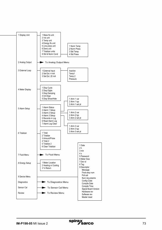
IM-P198-05 MI Issue 2 73
1 Device Setup
2 Process Variables
3 PV is4 PV5 AO1 Out6 PV % rnge7 Alrm Status
8 Diagnostics
9 Calibration Review
1 Display Unit
2 Analog Output
3 External Loop
4 Meter Display
5 Alarm Setup
6 Totalizer
7 Fluid Menu
8 Energy Setup
9 Device Menu
Diagnostics
Sensor Cal
Review
1 Mass flo unit2 Vol unit3 Temp unit4 Energy flo unit5 Line press unit6 Dens unit7 Totalizer units8 Std & Norm Cond
1 Disp Cycle2 Disp Digits3 Disp Damping4 Init Displ.5 Disp Show/Hide
1 Alarm Status2 Alarm 1 Setup3 Alarm 2 Setup4 Alarm 3 Setup5 Records in Log6 Read Alarm Log7 Alarm Log Clear
1 Total2 Totalize3 Amount/Pulse4 Total 25 Totalize 26 Clear Totalizer
1 Mass Flo2 Vol3 Temp4 Temp 25 Delta Temp.6 Energy flo7 Press8 Dens9 Totl Total 2
1 K Factor2 Ck Value3 Lo Flo Cutoff4 RTD1 Ro5 RTD1 alpha6 RTD1 beta7 RTD2 Ro8 RTD2 alpha9 RTD2 betaPcal B00, Pcal B01Pcal B02, Pcal B10Pcal B11, Pcal B12Pcal B20, Pcal B21Pcal B22Ref. ResistanceInternal Temp. CalCal currentFlow 1Deviation 1Flow 2Deviation 2Flow 3Deviation 3Flow 4Deviation 4Flow 5Deviation 5Flow 6Deviation 6Flow 7Deviation 7Flow 8Deviation 8Flow 9Deviation 9Flow 10Deviation 10
1 Alrm 1 var2 Alrm 1 typ3 Alrm 1 set pt
1 Alrm 2 var2 Alrm 2 typ3 Alrm 2 set pt
1 Alrm 3 var2 Alrm 3 typ3 Alrm 3 set pt
1 Norm Temp2 Norm Press3 Std Temp4 Std Press
1 External Input2 Set Ext. 4 mA3 Set Ext. 20 mA
InactiveTemp1Temp 2Pressure
1 Meter Location2 Heating or Cooling3 % Return
1 Date2 h3 min4 s5 Password6 Meter Size7 Dev id8 Tag9 Descriptor Message Final assy num Poll adr Num req preams Config Code Compile Date Compile Time Signal Board Version Hardware rev Software rev Master reset
To Analog Output Menu
To Fluid Menu
From Sensor Cal Menu,Calibration Review
To Diagnostics Menu
To Sensor Cal Menu
To Review Menu
To Diagnostics Menu

IM-P198-05 MI Issue 274
1 Fix Analog Output2 Trim Analog Output3 Configure AO14 PV is5 PV AO1 Out6 PV % rnge7 Configure AO28 SV is9 SV AO2 Out SV % rnge Configure AO3 TV is TV AO TV % rnge Configure AO4 QV is QV AO QV % rnge
1 PV is2 PV AO1 Out3 PV4 PV % rnge5 Apply values6 PV Rnge unit7 PV LRV8 PV URV9 PV AO1 Lo end pt PV AO1 Hi end pt PV AO1 Added damp
1 SV is2 SV AO2 Out3 SV4 SV % rnge5 Apply values6 SV Rnge unit7 SV LRV8 SV URV9 SV AO2 Lo end pt SV AO2 Hi end pt SV AO2 Added damp
1 TV is2 TV AO3 TV4 TV % rnge5 Apply values6 TV Rnge unit7 TV LRV8 TV URV9 TV AO3 Lo end pt TV AO3 Hi end pt TV AO3 Added damp
1 QV is2 QV AO3 QV4 QV % rnge5 Apply values6 QV Rnge unit7 QV LRV8 QV URV9 QV AO1 Lo end pt QV AO1 Hi end pt QV AO1 Added damp
From Online Menu
5.3.2 Analogue output menu

IM-P198-05 MI Issue 2 75
5.3.3 Fluid menu
1 Fluid2 Fluid Type
Water Ammonia Chlorine
Liquid Other Liquid Goyal-Dorais API-2540 Nat Gas AGA8 Real Gas Other Gas Liquified Gas
Other Liquid Density Viscosity Coef AL Viscosity Coef BL
Mol Weight Crit Press Crit TempCompressibilityALBL
Density @ 60F API K0 API K1 API AL API BL
AGA Ref Temp AGA Ref Press Specific Gravity Mole Fract N2 Mole Fract CO2
Steam Air Argon Ammonia CO CO2 Helium Hydrogen Methane Nitrogen Oxygen Propane
Specific gravity Compress Viscosity
Carbon Dioxide Nitrogen Hydrogen Oxygen Argon Nitrous Oxide
From Online Menu
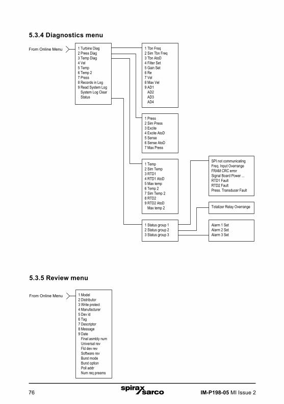
IM-P198-05 MI Issue 276
5.3.5 Review menu
5.3.4 Diagnostics menu1 Turbine Diag2 Press Diag3 Temp Diag4 Vel5 Temp6 Temp 27 Press8 Records in Log9 Read System Log System Log Clear Status
1 Tbn Freq2 Sim Tbn Freq3 Tbn AtoD4 Filter Set5 Gain Set6 Re7 Vel8 Max Vel9 AD1 AD2 AD3 AD4
1 Press2 Sim Press3 Excite4 Excite AtoD5 Sense6 Sense AtoD7 Max Press
1 Temp2 Sim Temp3 RTD14 RTD1 AtoD5 Max temp6 Temp 27 Sim Temp 28 RTD29 RTD2 AtoD Max temp 2
1 Status group 12 Status group 23 Status group 3
SPI not communicatingFreq. Input OverrangeFRAM CRC errorSignal Board Power ...RTD1 FaultRTD2 FaultPress. Transducer Fault
Totalizer Relay Overrange
Alarm 1 SetAlarm 2 SetAlarm 3 Set
1 Model2 Distributor3 Write protect4 Manufacturer5 Dev id6 Tag7 Descriptor8 Message9 Date Final asmbly num Universal rev Fld dev rev Software rev Burst mode Burst option Poll addr Num req preams
From Online Menu
From Online Menu
1 Turbine Diag2 Press Diag3 Temp Diag4 Vel5 Temp6 Temp 27 Press8 Records in Log9 Read System Log System Log Clear Status
1 Tbn Freq2 Sim Tbn Freq3 Tbn AtoD4 Filter Set5 Gain Set6 Re7 Vel8 Max Vel9 AD1 AD2 AD3 AD4
1 Press2 Sim Press3 Excite4 Excite AtoD5 Sense6 Sense AtoD7 Max Press
1 Temp2 Sim Temp3 RTD14 RTD1 AtoD5 Max temp6 Temp 27 Sim Temp 28 RTD29 RTD2 AtoD Max temp 2
1 Status group 12 Status group 23 Status group 3
SPI not communicatingFreq. Input OverrangeFRAM CRC errorSignal Board Power ...RTD1 FaultRTD2 FaultPress. Transducer Fault
Totalizer Relay Overrange
Alarm 1 SetAlarm 2 SetAlarm 3 Set
1 Model2 Distributor3 Write protect4 Manufacturer5 Dev id6 Tag7 Descriptor8 Message9 Date Final asmbly num Universal rev Fld dev rev Software rev Burst mode Burst option Poll addr Num req preams
From Online Menu
From Online Menu
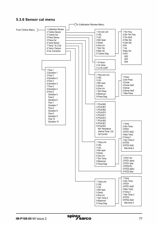
IM-P198-05 MI Issue 2 77
5.3.6 Sensor cal menu
1 Calibration Review2 Turbine Sensor3 Turbine Cal4 Press Sensor5 Press Cal6 Temp Sensor7 Temp 1 & 2 Cal8 Temp 2 Sensor9 Cal. Correction
1 Vol snsr unit2 USL3 LSL4 Min Span5 Damp6 Snsr s/n7 Sim Tbn8 Max Vel9 Turbine Diag
1 K Factor2 Ck Value3 Lo flo cutoff
1 Pres snsr unit2 USL3 LSL4 Min span5 Damp6 Snsr s/n7 Sim Press8 Maximum9 Press Diag
1 PCal B002 PCal B013 PCal B024 PCal B105 PCal B116 PCal B127 PCal B208 PCal B219 PCal B22 Ref. Resistance Internal Temp. Cal Cal Current
1 Temp unit2 USL3 LSL4 Min span5 Damp6 Snsr s/n7 Sim Temp8 Maximum9 Temp Diag
1 RTD1 Ro2 RTD1 alpha3 RTD1 beta4 RTD2 Ro5 RTD2 alpha6 RTD2 beta
1 Tbn Freq2 Sim Tbn Freq3 Tbn AtoD4 Filter Set5 Gain Set6 Re7 Vel8 Max Vel9 AD1 AD2 AD3 AD4
1 Press2 Sim Press3 Excite4 Excite AtoD5 Sense6 Sense AtoD7 Max Press
1 Temp2 Sim Temp3 RTD14 RTD1 AtoD5 Max Temp6 Temp 27 Sim Temp 28 RTD29 RTD2 AtoD Max temp 2
1 Temp unit2 USL3 LSL4 Min span5 Damp6 Snsr s/n7 Sim Temp 28 Maximum9 Temp Diag
1 Temp2 Sim Temp3 RTD14 RTD1 AtoD5 Max Temp6 Temp 27 Sim Temp 28 RTD29 RTD2 AtoD Max temp 2
1 Flow 12 Deviation 13 Flow 24 Deviation 25 Flow 36 Deviation 37 Flow 48 Deviation 49 Flow 5 Deviation 5 Flow 6 Deviation 6 Flow 7 Deviation 7 Flow 8 Deviation 8 Flow 9 Deviation 9 Flow 10 Deviation 10
From Online Menu
To Calibration Review Menu

IM-P198-05 MI Issue 278
5.4 HART commands with generic DD menu
1 Device Setup2 PV3 PV AO
4 PV LRV5 URV
1 Process Variables
2 Diag/Service
3 Basic Setup
4 Detailed Setup5 Review
1 Snsr2 AI % Rnge3 AO1
1 Distributor2 Model3 Dev id4 Tag5 Date6 Write Protect7 Descriptor8 Message9 PV snsr s/n Final assy # Revision #'s
1 Test Device2 Loop Test3 Calibration4 D/A Trim
1 Tag2 PV unit3 Range Values4 Device Information5 PV Xfer fnctn6 PV Damp
1 PV LRV2 PV URV3 PV LSL4 PV USL
1 Universal Rev2 Fld dev Rev3 Software Rev
1 4 mA2 20 mA3 Other4 End
1 Apply Values2 Enter Values
1 4 mA2 20 mA3 Exit
1 PV LRV2 PV URV3 PV USL4 PV LSL
1 Sensors
2 Signal Condition
3 Output Condition
4 Device Information
1 PV2 PV Sensor Unit3 Sensor information
1 Snsr Damp2 URV3 AI LRV4 Xfer Fnctn5 AI % rnge
1 Analog Output2 HART Output
1 Distributor2 Model3 Dev id4 Tag5 Date6 Write Protect7 Descriptor8 Message9 PV snsr s/n Final assy # Revision #'s
1 AO12 AO alarm typ3 Loop test4 D/A trim5 Scaled D/A trim
1 4 mA2 20 mA3 Other4 End
1 Poll addr2 Num req. preams3 Burst mode4 Burst option
1 Universal Rev2 Fld dev Rev3 Software Rev
1 PV LRV2 PV URV
PV LSL, PV USL, PV Min span
1 PV LRV2 PV URV
Online Menu
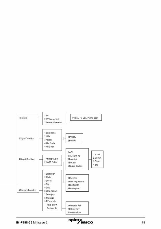
IM-P198-05 MI Issue 2 79
1 Device Setup2 PV3 PV AO
4 PV LRV5 URV
1 Process Variables
2 Diag/Service
3 Basic Setup
4 Detailed Setup5 Review
1 Snsr2 AI % Rnge3 AO1
1 Distributor2 Model3 Dev id4 Tag5 Date6 Write Protect7 Descriptor8 Message9 PV snsr s/n Final assy # Revision #'s
1 Test Device2 Loop Test3 Calibration4 D/A Trim
1 Tag2 PV unit3 Range Values4 Device Information5 PV Xfer fnctn6 PV Damp
1 PV LRV2 PV URV3 PV LSL4 PV USL
1 Universal Rev2 Fld dev Rev3 Software Rev
1 4 mA2 20 mA3 Other4 End
1 Apply Values2 Enter Values
1 4 mA2 20 mA3 Exit
1 PV LRV2 PV URV3 PV USL4 PV LSL
1 Sensors
2 Signal Condition
3 Output Condition
4 Device Information
1 PV2 PV Sensor Unit3 Sensor information
1 Snsr Damp2 URV3 AI LRV4 Xfer Fnctn5 AI % rnge
1 Analog Output2 HART Output
1 Distributor2 Model3 Dev id4 Tag5 Date6 Write Protect7 Descriptor8 Message9 PV snsr s/n Final assy # Revision #'s
1 AO12 AO alarm typ3 Loop test4 D/A trim5 Scaled D/A trim
1 4 mA2 20 mA3 Other4 End
1 Poll addr2 Num req. preams3 Burst mode4 Burst option
1 Universal Rev2 Fld dev Rev3 Software Rev
1 PV LRV2 PV URV
PV LSL, PV USL, PV Min span
1 PV LRV2 PV URV
Online Menu
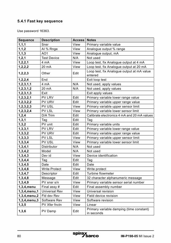
IM-P198-05 MI Issue 280
5.4.1 Fast key sequence
Use password 16363.
Sequence Description Access Notes1,1,1 Snsr View Primary variable value1,1,2 AI % Rnge View Analogue output % range1,1,3 AO1 View Analogue output, mA1,2,1 Test Device N/A Not used1,2,2,1 4 mA View Loop test, fix Analogue output at 4 mA1,2,2,2 20 mA View Loop test, fix Analogue output at 20 mA
1,2,2,3 Other Edit Loop test, fix Analogue output at mA value entered
1,2,2,4 End Exit loop test1,2,3,1,1 4 mA N/A Not used, apply values1,2,3,1,2 20 mA N/A Not used, apply values1,2,3,1,3 Exit Exit apply values1,2,3,2,1 PV LRV Edit Primary variable lower range value1,2,3,2,2 PV URV Edit Primary variable upper range value1,2,3,2,3 PV USL View Primary variable upper sensor limit1,2,3,2,4 PV LSL View Primary variable lower sensor limit1,2,4 D/A Trim Edit Calibrate electronics 4 mA and 20 mA values1,3,1 Tag Edit Tag1,3,2 PV unit Edit Primary variable units1,3,3,1 PV LRV Edit Primary variable lower range value1,3,3,2 PV URV Edit Primary variable upper range value1,3,3,3 PV LSL View Primary variable upper sensor limit1,3,3,4 PV USL View Primary variable lower sensor limit1,3,4,1 Distributor N/A Not used1,3,4,2 Model N/A Not used1,3,4,3 Dev id View Device identification1,3,4,4 Tag Edit Tag1,3,4,5 Date Edit Date1,3,4,6 Write Protect View Write protect1,3,4,7 Descriptor Edit Turbine flowmeter1,3,4,8 Message Edit 32 character alphanumeric message1,3,4,9 PV snsr s/n View Primary variable sensor serial number1,3,4,menu Final assy # Edit Final assembly number1,3,4,menu,1 Universal Rev View Universal revision1,3,4,menu,2 Fld dev Rev View Field device revision1,3,4,menu,3 Software Rev View Software revision1,3,5 PV Xfer fnctn View Linear
1,3,6 PV Damp Edit Primary variable damping (time constant) in seconds
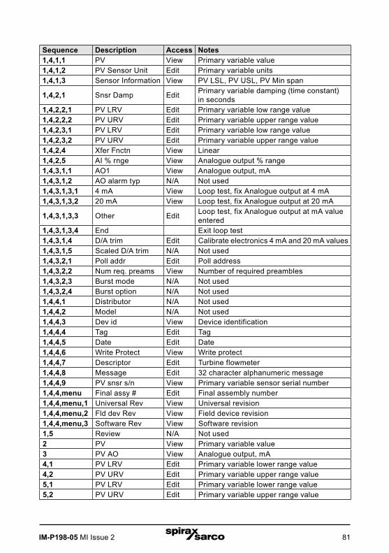
IM-P198-05 MI Issue 2 81
Sequence Description Access Notes1,4,1,1 PV View Primary variable value1,4,1,2 PV Sensor Unit Edit Primary variable units1,4,1,3 Sensor Information View PV LSL, PV USL, PV Min span
1,4,2,1 Snsr Damp Edit Primary variable damping (time constant) in seconds
1,4,2,2,1 PV LRV Edit Primary variable low range value1,4,2,2,2 PV URV Edit Primary variable upper range value1,4,2,3,1 PV LRV Edit Primary variable low range value1,4,2,3,2 PV URV Edit Primary variable upper range value1,4,2,4 Xfer Fnctn View Linear1,4,2,5 AI % rnge View Analogue output % range1,4,3,1,1 AO1 View Analogue output, mA1,4,3,1,2 AO alarm typ N/A Not used1,4,3,1,3,1 4 mA View Loop test, fix Analogue output at 4 mA1,4,3,1,3,2 20 mA View Loop test, fix Analogue output at 20 mA
1,4,3,1,3,3 Other Edit Loop test, fix Analogue output at mA value entered
1,4,3,1,3,4 End Exit loop test1,4,3,1,4 D/A trim Edit Calibrate electronics 4 mA and 20 mA values1,4,3,1,5 Scaled D/A trim N/A Not used1,4,3,2,1 Poll addr Edit Poll address1,4,3,2,2 Num req. preams View Number of required preambles1,4,3,2,3 Burst mode N/A Not used1,4,3,2,4 Burst option N/A Not used1,4,4,1 Distributor N/A Not used1,4,4,2 Model N/A Not used1,4,4,3 Dev id View Device identification1,4,4,4 Tag Edit Tag1,4,4,5 Date Edit Date1,4,4,6 Write Protect View Write protect1,4,4,7 Descriptor Edit Turbine flowmeter1,4,4,8 Message Edit 32 character alphanumeric message1,4,4,9 PV snsr s/n View Primary variable sensor serial number1,4,4,menu Final assy # Edit Final assembly number1,4,4,menu,1 Universal Rev View Universal revision1,4,4,menu,2 Fld dev Rev View Field device revision1,4,4,menu,3 Software Rev View Software revision1,5 Review N/A Not used2 PV View Primary variable value3 PV AO View Analogue output, mA4,1 PV LRV Edit Primary variable lower range value4,2 PV URV Edit Primary variable upper range value5,1 PV LRV Edit Primary variable lower range value5,2 PV URV Edit Primary variable upper range value
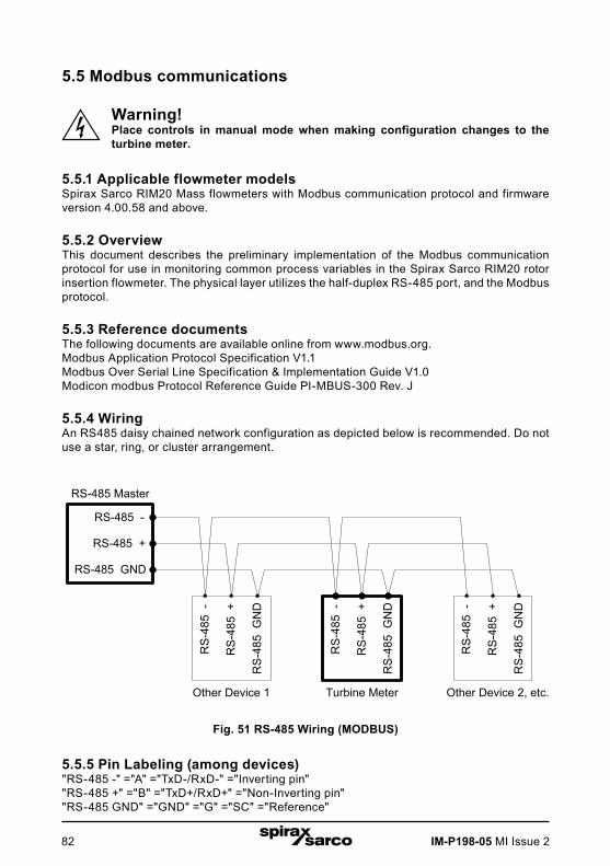
IM-P198-05 MI Issue 282
5.5 Modbus communications
Warning!Place controls in manual mode when making configuration changes to the turbine meter.
5.5.1 Applicable flowmeter modelsSpirax Sarco RIM20 Mass flowmeters with Modbus communication protocol and firmware version 4.00.58 and above.
5.5.2 OverviewThis document describes the preliminary implementation of the Modbus communication protocol for use in monitoring common process variables in the Spirax Sarco RIM20 rotor insertion flowmeter. The physical layer utilizes the half-duplex RS-485 port, and the Modbus protocol.
5.5.3 Reference documentsThe following documents are available online from www.modbus.org.Modbus Application Protocol Specification V1.1Modbus Over Serial Line Specification & Implementation Guide V1.0Modicon modbus Protocol Reference Guide PI-MBUS-300 Rev. J
5.5.4 WiringAn RS485 daisy chained network configuration as depicted below is recommended. Do not use a star, ring, or cluster arrangement.
Fig. 51 RS-485 Wiring (MODBUS)
5.5.5 Pin Labeling (among devices)"RS-485 -" ="A" ="TxD-/RxD-" ="Inverting pin""RS-485 +" ="B" ="TxD+/RxD+" ="Non-Inverting pin""RS-485 GND" ="GND" ="G" ="SC" ="Reference"
RS-485 -
RS-485 +
RS-485 GND
RS-485 Master
Turbine Meter
RS
-485
-
RS
-485
+
RS
-485
GN
D
RS
-485
-
RS
-485
+
RS
-485
GN
D
Other Device 2, etc.
RS
-485
-
RS
-485
+
RS
-485
GN
D
Other Device 1
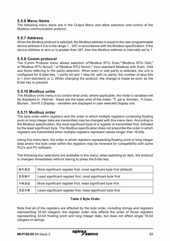
IM-P198-05 MI Issue 2 83
5.5.6 Menu ItemsThe following menu items are in the Output Menu and allow selection and control of the Modbus communication protocol.
5.5.7 AddressWhen the Modbus protocol is selected, the Modbus address is equal to the user programmable device address if it is in the range 1…247, in accordance with the Modbus specification. If the device address is zero or is greater than 247, then the Modbus address is internally set to 1.
5.5.8 Comm protocolThe Comm Protocol menu allows selection of"Modbus RTU Even,""Modbus RTU Odd," or"Modbus RTU None2," or"Modbus RTU None1," (non-standard Modbus) with Even, Odd and None referring to the parity selection. When even or odd parity is selected, the unit is configured for 8 data bits, 1 parity bit and 1 stop bit; with no parity, the number of stop bits is 1 (non-standard) or 2. When changing the protocol, the change is made as soon as the Enter key is pressed.
5.5.10 Modbus unitsThe Modbus Units menu is to control what units, where applicable, the meter’s variables will be displayed in. Internal - these are the base units of the meter, °F, psi a, lbm/sec , ft 3/sec, Btu/sec , lbm/ft 3 Display - variables are displayed in user selected display unit.
5.5.11 Modbus orderThe byte order within registers and the order in which multiple registers containing floating point or long integer data are transmitted may be changed with this menu item. According to the Modbus specification, the most significant byte of a register is transmitted first, followed by the least significant byte. The Modbus specification does not prescribe the order in which registers are transmitted when multiple registers represent values longer than 16 bits.
Using this menu item, the order in which registers representing floating point or long integer data and/or the byte order within the registers may be reversed for compatibility with some PLCs and PC software.
The following four selections are available in this menu; when selecting an item, the protocol is changed immediately without having to press the Enter key.
0-1:2-3 Most significant register first, most significant byte first (default)
2-3:0-1 Least significant register first, most significant byte first
1-0:3-2 Most significant register first, least significant byte first
3-2:1-0 Least significant register first, least significant byte first
Table 2 Byte Order
Note that all of the registers are affected by the byte order, including strings and registers representing 16-bit integers; the register order only affects the order of those registers representing 32-bit floating point and long integer data, but does not affect single 16-bit integers or strings.

IM-P198-05 MI Issue 284
5.5.12 Modbus protocolThe Modbus RTU protocol is supported in this implementation. Supported baud rates are 1200, 2400, 4800, 9600, 19200, 38400, 57600, and 115200. The default baud rate is 19200 baud. Depending upon the Modbus protocol selected, data are transmitted in 8-bit data frames with even or odd parity and 1 stop bit, or no parity and 2 or 1 (non-standard) stop bits.The current Modbus protocol specification does not define register usage, but there is an informal register numbering convention derived from the original (now obsolete) Modicon modbus protocol specification, and used by many vendors of Modbus capable products.
Registers Usage Valid function codes
00001-09999 Read/write bits ("coils")01 (read coils) 05 (write single coil)15 (write multiple coils)
10001-19999 Read-only bits ("discrete inputs") 02 (read discrete inputs)
30001-39999
Read-only 16 bit registers ("inputregisters"), IEEE 754 floating point register pairs, arbitrary length strings encoded as two ASCII characters per 16- bit register
03 (read holding registers) 04 (read input registers)
40001-49999
Read/write 16-bit registers ("holding registers"), IEEE 754 floating point register pairs, arbitrary length strings encoded as two ASCII characters per 16- bit register
03 (read holding registers) 06 (write single register) 16 (write multiple registers)
Each range of register numbers maps to a unique range of addresses that are determined by the function code and the register number. The address is equal to the least significant four digits of the register number minus one, as shown in the following table.
Registers Function codes Data type and address range
00001-09999 01, 05, 15 Read/write bits 0000-9998
10001-19999 02 Read-only bits 0000-9999
30001-39999 03, 04 Read-only 16-bit registers 0000-9998
40001-49999 03, 06, 16 Read/write 16-bit registers 0000-9998
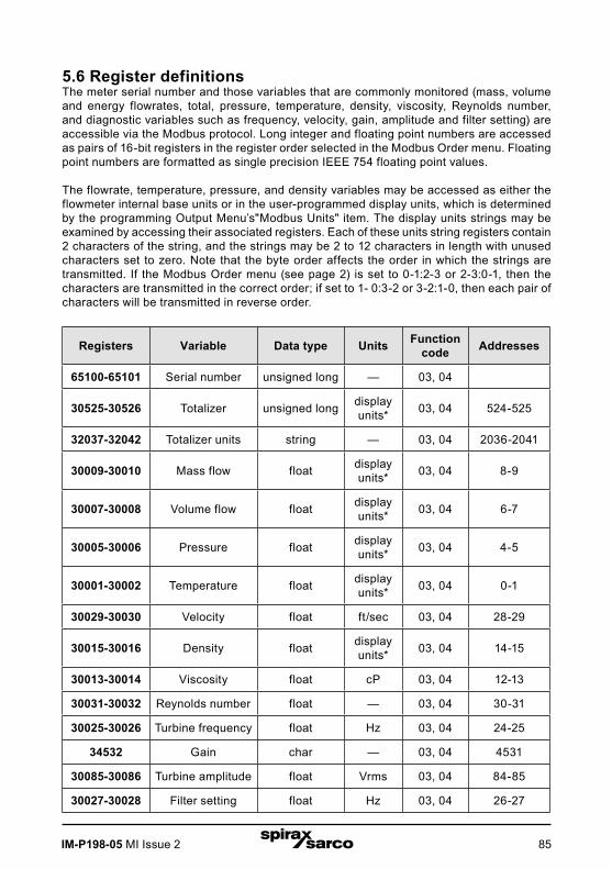
IM-P198-05 MI Issue 2 85
5.6 Register definitionsThe meter serial number and those variables that are commonly monitored (mass, volume and energy flowrates, total, pressure, temperature, density, viscosity, Reynolds number, and diagnostic variables such as frequency, velocity, gain, amplitude and filter setting) are accessible via the Modbus protocol. Long integer and floating point numbers are accessed as pairs of 16-bit registers in the register order selected in the Modbus Order menu. Floating point numbers are formatted as single precision IEEE 754 floating point values.
The flowrate, temperature, pressure, and density variables may be accessed as either the flowmeter internal base units or in the user-programmed display units, which is determined by the programming Output Menu’s"Modbus Units" item. The display units strings may be examined by accessing their associated registers. Each of these units string registers contain 2 characters of the string, and the strings may be 2 to 12 characters in length with unused characters set to zero. Note that the byte order affects the order in which the strings are transmitted. If the Modbus Order menu (see page 2) is set to 0-1:2-3 or 2-3:0-1, then the characters are transmitted in the correct order; if set to 1- 0:3-2 or 3-2:1-0, then each pair of characters will be transmitted in reverse order.
Registers Variable Data type Units Function code Addresses
65100-65101 Serial number unsigned long — 03, 04
30525-30526 Totalizer unsigned long display units* 03, 04 524-525
32037-32042 Totalizer units string — 03, 04 2036-2041
30009-30010 Mass flow float display units* 03, 04 8-9
30007-30008 Volume flow float display units* 03, 04 6-7
30005-30006 Pressure float display units* 03, 04 4-5
30001-30002 Temperature float display units* 03, 04 0-1
30029-30030 Velocity float ft/sec 03, 04 28-29
30015-30016 Density float display units* 03, 04 14-15
30013-30014 Viscosity float cP 03, 04 12-13
30031-30032 Reynolds number float — 03, 04 30-31
30025-30026 Turbine frequency float Hz 03, 04 24-25
34532 Gain char — 03, 04 4531
30085-30086 Turbine amplitude float Vrms 03, 04 84-85
30027-30028 Filter setting float Hz 03, 04 26-27

IM-P198-05 MI Issue 286
Table 3 Register DefinitionsThe following registers are available with the energy meter firmware:
Registers Variable Data type Units Function code Addresses
30527-30528 Totalizer #2 unsigned long display units* 03, 04 526-527
32043-32048 Totalizer #2 units string — 03, 04 2042-2047
30003-30004 Temperature #2 float display units* 03, 04 2-3
30011-30012 Energy flow float display units* 03, 04 10-11
The following registers contain the display units strings:
Registers Variable Data type Units Function code Addresses
32007-32012 Volume flow units string — 03, 04 2006-2011
32001-32006 Mass flow units string — 03, 04 2000-2005
32025-32030 Temperature units string — 03, 04 2024-2029
32019-32024 Pressure units string — 03, 04 2018-2023
32031-32036 Density units string — 03, 04 2030-2035
32013-32017 Energy flow units string — 03, 04 2012-2017
Function codes 03 (read holding registers) and 04 (read input registers) are the only codes supported for reading these registers, and function codes for writing holding registers are not implemented. We recommend that the floating point and long integer registers be read in a single operation with the number of registers being a multiple of two. If these data are read in two separate operations, each reading a single 16-bit register, then the value will likely be invalid.
The floating point registers with values in display units are scaled to the same units as are displayed, but are instantaneous values that are not smoothed. If display smoothing is enabled (non-zero value entered in the Display TC item in the Display Menu), then the register values will not agree exactly with the displayed values.

IM-P198-05 MI Issue 2 87
5.6.1 Exception status definitionsThe Read Exception Status command (function code 07) returns the exception status byte, which is defined as follows. This byte may be cleared by setting"coil" register #00003 (function code 5, address 2, data = 0xff00).
Bit(s) Definition
0-1 Byte order (see Modbus Order on page 2) 0 = 3-2:1-0 1 = 2-3:0-12 = 1-0:3-2 3 = 0-1:2-3
2 Temperature sensor fault
3 Pressure sensor fault
4 A/D converter fault
5 Period overflow
6 Pulse overflow
7 Configuration changed
5.6.2 Discrete input definitionsThe status of the three alarms may be monitored via the Modbus Read Discrete Input command (function code 02). The value returned indicates the state of the alarm, and will be 1 only if the alarm is enabled and active. A zero value is transmitted for alarms that are either disabled or inactive,
Registers Variable Function code Address
10001 Alarm #1 state 02 0
10002 Alarm #2 state 02 1
10003 Alarm #3 state 02 2
5.6.3 Control register definitionsThe only writeable registers in this implementation are the Reset Exception Status, Reset Meter and Reset Totalizer functions, which are implemented as"coils" which may be written with the Write Single Coil command (function code 05) to address 8 through 10, respectively, (register #00009 through #00011).
The value sent with this command must be either 0x0000 or 0xff00, or the meter will respond with an error message; the totalizer will be reset or exception status cleared only with a value of 0xff00.

IM-P198-05 MI Issue 288
5.6.4 Error responsesIf an error is detected in the message received by the unit, the function code in the response is the received function code with the most significant bit set, and the data field will contain the exception code byte, as follows:
Exception Code Description
01 Invalid function code — function code not supported by device
02 Invalid data address — address defined by the start address and number of registers is out of range
03 Invalid data value — number of registers = 0 or >125 or incorrect data with the Write Single Coil command
If the first byte of a message is not equal to the unit’s Modbus address, if the unit detects a parity error in any character in the received message (with even or odd parity enabled), or if the message CRC is incorrect, the unit will not respond.
5.6.5 Command message formatThe start address is equal to the desired first register number minus one. The addresses derived from the start address and the number of registers must all be mapped to valid defined registers, or an invalid data address exception will occur.
Device address
Function code
Start address N = Number of registers CRC
8 bits, 1... 247 8 bits 16 bits, 0... 9998 16 bits, 1 ... 125 16 bits
5.6.6 Normal response message format
Device address
Function code
Byte count Data CRC
8 bits, 1... 247 8 bits 8 bits (N) 16-bit registers 16 bits
5.6.7 Exception response message format
Device address
Function code
Exception code CRC
8 bits, 1... 247 8 bits 8 bits 16 bits

IM-P198-05 MI Issue 2 89
5.6.8 Examples
Read the exception status byte from the device with address 1:
01 07 41 E2
01 Device address07 Function code, 04 = read exception status
A typical response from the device is as follows:
01 07 03 62 31
01 Device address07 Function code03 Exception status byte62 31 CRC
Request the first 12 registers from device with address 1:
01 04 00 00 00 0C F0 0F
01 Device address04 Function code, 04 = read input register00 00 Starting address00 0C Number of registers = 12F0 0F CRC
A typical response from the device is as follows: *note these are the older register definitions
01 04 18 00 00 03 E8 00 00 7A 02 6C 62 00 00 41 BA 87 F2 3E BFFC 6F 42 12 EC 8B 4D D1
01 Device address04 Function code18 Number of data bytes = 2400 00 03 E8 Serial number = 1000 (unsigned long)00 00 7A 02 Totalizer = 31234 lbm (unsigned long)6C 62 00 00 Totalizer units ="lb" (string, unused charactersare 0)41 BA 87 F2 Mass flowrate = 23.3164 lbm/sec (float)3E BF FC 6F Volume flowrate = 0.3750 ft3 /sec (float)42 12 EC 8B Pressure = 36.731 psi a (float)4D D1 CRC
An attempt to read register(s) that don’t exist
01 04 00 00 00 50 F1 D2
01 Device address04 Function code 4 = read input register00 00 Starting address00 50 Number of registers = 80F0 36 CRC

IM-P198-05 MI Issue 290
results in an error response as follows:
01 84 02 C2 C1
01 Device address84 Function code with most significant bit set indicateserror response02 Exception code 2 = invalid data addressC2 C1 CRC
Request the state all three alarms:
01 02 00 00 00 03 38 0B
01 Device address02 Function code 2 = read discrete inputs00 00 Starting address00 03 Number of inputs = 338 0B CRC
and the unit responds with:
01 02 01 02 20 49
01 Device address02 Function code01 Number of data bytes = 102 Alarm #2 on, alarms #1 and #3 off20 49 CRC
To reset the totalizer:
01 05 00 00 FF 00 8C 3A
01 Device address05 Function code 5 = write single coil00 09 Coil address = 9FF 00 Data to reset totalizer8C 3A CRC (not the correct CRC EJS-02-06-07)
The unit responds with an identical message to that transmitted, and the totalizer is reset. If the"coil" is turned off as in the following message, the response is also identical to the transmitted message, but the totalizer is not affected.
01 05 00 00 00 00 CD CA
01 Device address05 Function code 5 = write single coil00 00 Coil address = 000 00 Data to"turn off coil" does not reset totalizerCD CA CRC
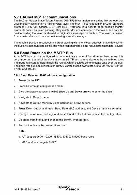
IM-P198-05 MI Issue 2 91
5.7 BACnet MS/TP communicationsThe BACnet Master-Slave/Token-Passing (MS/TP) driver implements a data link protocol that uses the services of the RS-485 physical layer. The MS/TP bus is based on BACnet standardprotocol SSPC-135, Clause 9. BACnet MS/TP protocol is a peer-to-peer, multiple master protocols based on token passing. Only master devices can receive the token, and only the device holding the token is allowed to originate a message on the bus. The token is passed from master device to master device using a small message.
The token is passed in consecutive order starting with the lowest address. Slave devices on the bus only communicate on the bus when responding to a data request from a master device.
5.8 Baud Rates on the MS/TP BusAn mS/TP bus can be configured to communicate at one of four different baud rates. It is very important that all of the devices on an mS/TP bus communicate at the same baud rate. The baud rate setting determines the rate at which devices communicate data over the bus. The baud rate settings available on RIM20 Vortex Mass flowmeters are 9600, 19200, 38400, 57600 and 115200
5.8.1 Baud Rate and MAC address configuration
1. Power on the IUT
2. Press Enter to go configuration menu
3. Give the factory password 16363 (Use Up and Down arrows to enter the digits)
4. Navigate to Output menu
5. Navigate to Output Menu by using right or left arrow buttons
6. Press Down button and reach Baud Rate MAC address, and Device Instance screens
7. Change the required settings and press Exit & Enter buttons to save the configuration
8. Do steps from b to g, and change the comm. Type as Hart.
9. Reboot the device by power off and on.
Note:
a. IUT support 9600, 19200, 38400, 57600, 115200 baud rates
b. MAC address range is 0-127

IM-P198-05 MI Issue 292
5.9 Supported BACnet objectsA BACnet object represents physical or virtual equipment information, as a digital input or parameters. The RIM20 Vortex Mass flowmeters presents the following object types:
a. Device Object
b. Analogue Input
c. Binary Input
d. Binary Value
Each object type defines a data structure composed by properties that allow the access to the object information. The below table shows the implemented properties for each Vortex Mass flowmeters object type.
Properties Object Types
Device Analogue input
Binary input
Binary value
Object_Identifier
Object_Name
Object_Type
System_Status
Vendor_Name
Vendor_Identifier
Model_Name
Firmware_Revision
Application-Software-Version
Protocol_Version
Protocol_Revision
Protocol_Services_Supported
Protocol_Object_Types_Supported
Object_List
Max_ADPU_Length_Accepted
Segmentation_Supported
ADPU_Timeout
Number_Of_ADPU_Retries

IM-P198-05 MI Issue 2 93
Properties Object Types
Device Analogue input
Binary input
Binary value
Max_Masters
Max_Info_Frames
Device_Address_Binding
Database_Revision
Status_Flags
Event_State
Reliability
Out_Of_Service (W) (W) (W)
Units
Polarity (W)
Priority_Array
Relinquish_Default
Status_Flag
Present_Value (W) (W) (W)
Inactive_Text
Active_Text (W) - Writable Property.
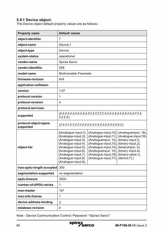
IM-P198-05 MI Issue 294
5.9.1 Device object:The Device object default property values are as follows -
Property name Default values
object-identifier 7
object-name Device,1
object-type Device
system-status operational
vendor-name Spirax Sarco
vendor-identifier 558
model-name Multivariable Flowmete
firmware-revision N/A
application-software-
version 1.07
protocol-version 1
protocol-revision 4
protocol-services-
supported {F,F,F,F,F,F,F,F,F,F,F,F,T,F,T,T,T,T,F,F,F,F,F,F,F,F,F,F,F,F,T,T,F,F,F,F,F}
protocol-object-types- supported {T,F,F,T,F,T,F,F,T,F,F,F,F,F,F,F,F,F,F,F,F,F,F,F,F}
object-list
{(Analogue-input,1),(Analogue-input,2),(Analogue-input,3),(Analogue-input,4), (Analogue-input,5), (Analogue-input,6),(Analogue-input,7),(Analogue-input,8)(Analogue-input,9),
(Analogue-input,10), (Analogue-input,11), (Analogueinput, 12), (Analogue-input,13),(Analogue-input,14), (Analogueinput, 15),(Analogue-input,16),(Analogue-input,17),
(Analogueinput, 18),(Analogue-input,19),(binary-input,1),(binary-input,2),(binaryinput, 3),(binary-input,4), (binary-value,1), (device,7) }
max-apdu-length-accepted 300
segmentation-supported no-segmentation
apdu-timeout 3000
number-of-APDU-retries 1
max-master 127
max-info-frames 1
device-address-binding ()
database-revision 0
Note - Device Communication Control: Password -"Spirax Sarco"

IM-P198-05 MI Issue 2 95
5.9.2 Analogue input object:Vortex Mass flowmeters Analogue Input type objects are described in the below Table -
Object instance
Object name Unit Description
1 Volume flow
cubic-feet-per-second, cubic-feet-per-minute, us-gallons-per-minute, imperial-gallons-per- minute,litres-per-minute, litres-per-second, litres-per-hour,cubic-meters-per-second, cubic-meters-per-minute, cubic-meters-per-hour
This AI object is used to measure volume flow.
2 Mass flow
pounds-mass-per-second, grams-per-second, kilograms-per-second , kilograms-per-minute , kilograms-per-hour, pounds-mass-per-minute ,pounds-mass-per-hour, tons-per-hour,grams-per-second , grams-per-minute
This AI object is used to measure mass flow.
3 Temperature 1degrees-Celsius, degrees-Kelvin, degrees-Fahrenheit
This AI object measures temperature in one of the given Unit.
4 Temperature 2degrees-Celsius,degrees-Kelvin, degrees-Fahrenheit
This AI object measures temperature in one of the given Unit.
5 Pressure
pounds-force-per-square-","-of-water,"-of-mercury, millimeters-of-mercury, bars,millibars, pascals, kilopascals
TBD
6 Density kilograms-per-cubic-meter TBD
7 Energy Flow
Kilowatts, Horsepower, btus-per-hour,,kilo-btus-per-hour, megawatts
TBD

IM-P198-05 MI Issue 296
Object instance
Object name Unit Description
8Totalizer 1
& Totalizer 2
If Totalizer selection forMass measure -pounds-mass-per-second, grams-per-second, kilograms-per-second , kilograms-per-minute , kilograms-per-hour, pounds-mass-per-minute , pounds-mass-per-hour, tons-per-hour,grams-per-second ,grams-per-minute
If Totalizer selection for Volume measure - cubic-feet-per-second, cubic-feet-per-minute, us-gallons-per-minute, imperial-gallons-per-minute,litres-per-minute, litres-per-second, litres-per-hour,cubic-meters-per-second, cubic-meters-per-minute, cubic-meters-per-hour
If Totalizer selection for Energy measure - Kilowatts,Horsepower,btus-per-hour,, kilo-btus-per-hour, megawatts
An electronic counter which records the total accumulated flow over a certain range of time.
10 StatusRegister NO UNITS TBD
11 Channel 1 (4-20mA) milliamperes TBD
12 Channel 2 (4-20mA) milliamperes TBD
13 Channel 3 (4-20mA) milliamperes TBD
14 Scaled Freq hertz TBD
15 Flow Velocity feet-per-second TBD
16 Viscosity centipoises TBD
17 Frequency hertz TBD
18 VorTex Amp millivolts TBD
19 FilterSetting hertz TBD
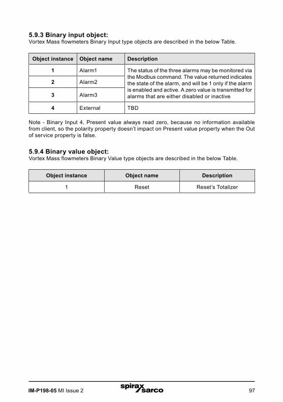
IM-P198-05 MI Issue 2 97
5.9.3 Binary input object:Vortex Mass flowmeters Binary Input type objects are described in the below Table.
Object instance Object name Description
1 Alarm1 The status of the three alarms may be monitored via the Modbus command. The value returned indicates the state of the alarm, and will be 1 only if the alarm is enabled and active. A zero value is transmitted for alarms that are either disabled or inactive
2 Alarm2
3 Alarm3
4 External TBD
Note - Binary Input 4, Present value always read zero, because no information available from client, so the polarity property doesn’t impact on Present value property when the Out of service property is false.
5.9.4 Binary value object:Vortex Mass flowmeters Binary Value type objects are described in the below Table.
Object instance Object name Description
1 Reset Reset’s Totalizer

IM-P198-05 MI Issue 298
5.10 ANNEX - BACnet protocol implementation conformance statementDate: 19-April-2012
Applications Software Version: 1.07
Firmware Revision: N/A
BACnet Protocol Revision: 4
BACnet Standardized Device Profile (Annex L): BACnet Operator Workstation (B-OWS) BACnet Advanced Operator Workstation (B-AWS) BACnet Operator Display (B-OD) BACnet Building Controller (B-BC) BACnet Advanced Application Controller (B-AAC) BACnet Application Specific Controller (B-ASC) BACnet Smart Sensor (B-SS) BACnet Smart Actuator (B-SA)
5.10.1 List all BACnet interoperability building blocks supported (Annex K):
BIBBs
DS-RP-B
DS-WP-B
DM-DDB-B
DM-DOB-B
DM-dcC-B
DS-RPM-B
DS-WPM-B
Services supported
Read Property Execute
Write Property Execute
Read Property Multiple Execute
Write Property Multiple Execute
Who-Is Execute
I-Am Initiate
Who-Has Execute
I-Have Initiate
Device Communication Control Execute

IM-P198-05 MI Issue 2 99
5.10.2 Segmentation capability: Able to transmit segmented messages - Window Size Able to receive segmented messages - Window Size
5.10.3 Standard object types supported
Standard object types supported
Object type Dynamicallycreatable
Dynamicallydeleteable
Additionalwritable
properties
Rangerestrictions
Analogue Input (AI) No No None None
Binary Input (BV) No No None None
Binary Value No No None None
Device No No None None
Standard object types supported writable properties
Object type Properties
Analogue Input (AI) Present Value Out-Of-Service
Binary Input (BV) Present Value Out-Of-Service Polarity
Binary Value Present Value Out-Of-Service
Device
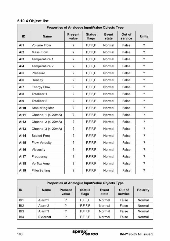
IM-P198-05 MI Issue 2100
5.10.4 Object listProperties of Analogue Input/Value Objects Type
ID Name Presentvalue
Statusflags
Eventstate
Out ofservice Units
AI1 Volume Flow ? F,F,F,F Normal False ?
AI2 Mass Flow ? F,F,F,F Normal False ?
AI3 Temperature 1 ? F,F,F,F Normal False ?
AI4 Temperature 2 ? F,F,F,F Normal False ?
AI5 Pressure ? F,F,F,F Normal False ?
AI6 Density ? F,F,F,F Normal False ?
AI7 Energy Flow ? F,F,F,F Normal False ?
AI8 Totalizer 1 ? F,F,F,F Normal False ?
AI9 Totalizer 2 ? F,F,F,F Normal False ?
AI10 StatusRegister ? F,F,F,F Normal False ?
AI11 Channel 1 (4-20mA) ? F,F,F,F Normal False ?
AI12 Channel 2 (4-20mA) ? F,F,F,F Normal False ?
AI13 Channel 3 (4-20mA) ? F,F,F,F Normal False ?
AI14 Scaled Freq ? F,F,F,F Normal False ?
AI15 Flow Velocity ? F,F,F,F Normal False ?
AI16 Viscosity ? F,F,F,F Normal False ?
AI17 Frequency ? F,F,F,F Normal False ?
AI18 VorTex Amp ? F,F,F,F Normal False ?
AI19 FilterSetting ? F,F,F,F Normal False ?
Properties of Analogue Input/Value Objects Type
ID Name Presentvalue
Statusflags
Eventstate
Out ofservice
Polarity
BI1 Alarm1 ? F,F,F,F Normal False Normal
BI2 Alarm2 ? F,F,F,F Normal False Normal
BI3 Alarm3 ? F,F,F,F Normal False Normal
BI4 External ? F,F,F,F Normal False Normal

IM-P198-05 MI Issue 2 101
Properties of Analogue Input/Value Objects Type
ID Name Presentvalue
Statusflags
Eventftate
Out offervice
out-of-service
BV1 Reset ? F,F,F,F Normal False False
5.10.5 Data link layer options: BACnet IP, (Annex J) BACnet IP, (Annex J), Foreign Device ISO 8802-3, Ethernet (Clause 7) ANSI/ATA 878.1, 2.5 Mb. ARCNET (Clause 8) ANSI/ATA 878.1, EIA-485 ARCNET (Clause 8), baud rate(s) MS/TP master (Clause 9), baud rate(s): 9600, 19200, 38400 MS/TP slave (Clause 9), baud rate(s): Point-To-Point, EIA 232 (Clause 10), baud rate(s): Point-To-Point, modem, (Clause 10), baud rate(s): LonTalk, (Clause 11), medium: Other:
5.10.6 Device address binding:Is static device binding supported? (This is currently necessary for two- way communication with MS/TP slaves and certain other devices.) : Yes No
5.10.7 Networking options: Router, Clause 6 - List all routing configurations, e.g., ARCNET- Ethernet, Ethernet-MS/TP, etc. Annex H, BACnet Tunneling Router over IP BACnet/IP Broadcast Management Device (BBMD) Does the BBMD support registrations by Foreign Devices? Yes No Does the BBMD support network address translation? Yes No
5.10.8 Network security options: Non-secure Device - is capable of operating without BACnet Network Security Secure Device - is capable of using BACnet Network Security (NS-SD BVBB) Multiple Application-Specific Keys: Supports encryption (NS-ED BVBB) Key Server (NS-KS BVBB)
5.10.9 Character sets supported:Indicating support for multiple character sets does not imply that they can all be supported simultaneously. ANSI X3.4 IBM™/Microsoft™DBCS ISO 8859-1 ISO 10646 (UCS-2) ISO 10646 (UCS-4) JIS C 6226
If this product is a communication gateway, describe the types of non- BACnet equipment/networks(s) that the gateway supports:
N/A
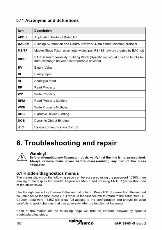
IM-P198-05 MI Issue 2102
5.11 Acronyms and definitions
Item Description
APDU Application Protocol Data Unit
BACnet Building Automation and Control Network- Data communication protocol
MS/TP Master-Slave Token passing(a twisted pair RS485 network created by BACnet)
BIBB BACnet Interoperability Building Block (Specific individual function blocks for data exchange between interoperable devices).
BV Binary Value
BI Binary Input
AI Analogue Input
RP Read Property
WP Write Property
RPM Read Property Multiple
WPM Write Property Multiple.
DDB Dynamic Device Binding
DOB Dynamic Object Binding
dcC Device communication Control
6. Troubleshooting and repairWarning!Before attempting any flowmeter repair, verify that the line is not pressurized.Always remove main power before disassembling any part of the mass flowmeter.
6.1 Hidden diagnostics menusThe menus shown on the following page can be accessed using the password 16363, then moving to the display that reads"Diagnostics Menu" and pressing ENTER (rather than one of the arrow keys).
Use the right arrow key to move to the second column. Press EXIT to move from the second column back to the first, press EXIT while in the first column to return to the setup menus.Caution: password 16363 will allow full access to the configuration and should be used carefully to avoid changes that can adversely alter the function of the meter.
Each of the menus on the following page will first be defined followed by specific troubleshooting steps.
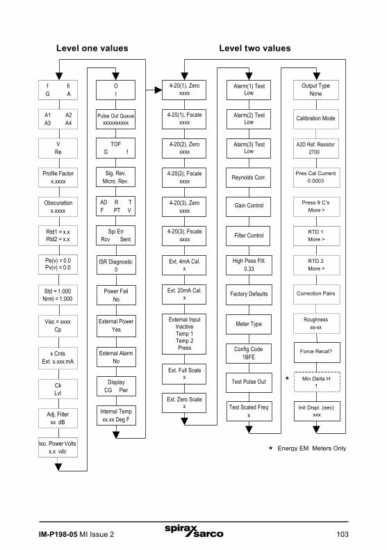
IM-P198-05 MI Issue 2 103
Reynolds Corr.
Gain Control
High Pass Filt.0.33
Factory Defaults
Meter Type
Config Code 1BFE
Test Pulse Out
Test Scaled Freq x
OI
Pulse Out Queuexxxxxxxxxx
TOFG f
Sig. Rev. Micro. Rev.
AD R TF PT V
Spi ErrRcv Sent
ISR Diagnostic 0
Power Fail No
External PowerYes
External AlarmNo
Display CG Pwr
Internal Tempxx.xx Deg F
4-20(1), Zeroxxxx
Alarm(1) TestLow
4-20(1), Fscalexxxx
Alarm(2) TestLow
4-20(2), Zeroxxxx
Alarm(3) TestLow
4-20(2), Fscalexxxx
4-20(3), Zeroxxxx
4-20(3), Fscale xxxx Filter Control
Ext. 4mA Cal.x
Ext. 20mA Cal. x
External Input Inactive Temp 1Temp 2Press Force Recal?
Ext. Full Scalex * Min Delta H
1
Ext. Zero Scalex Init Displ. (sec)
xxx
* Energy EM Meters Only
f fiG A
A1 A2A3 A4
V
Re
Profile Factor
x.xxxx
Obscuration
x.xxxx
Rtd1 = x.xRtd2 = x.x
Pe(v) = 0.0Pv(v) = 0.0
Std = 1.000
Nrml = 1.000
Visc = xxxx
Cp
x Cnts
Ext x.xxx mA
CkLvl
Adj. Filterxx dB
Iso. Power Volts
x.x vdc
Output TypeNone
Calibration Mode
A2D Ref. Resistor
2700
Pres Cal Current
0.0003
Press 9 C’s
More >
RTD 1More >
RTD 2More >
Correction Pairs
Roughness
xe-xx
Level one values Level two values

IM-P198-05 MI Issue 2104
6.2 Level one hidden diagnostics valuesf Turbine frequency (Hz).
fi
Adaptive filter - should be approximately 25% higher than the turbine frequency, this is a low-pass filter. If the meter is using the Filter Control (see below) in the manual mode, fi will be displayed as fm.
G Gain (applied to turbine signal amplitude). Gain defaults to 1.0 and can be changed using the Gain Control (see below).
A Amplitude of turbine signal in Volts rms.
A1, A2, A3, A4
A/D counts representing the turbine signal amplitude. Each stage (A1-A4) cannot exceed 512. Beginning with stage A1, the A/D counts increase as the flow increases.When stage A1 reaches 512, it will shift to stage A2. This will continue as the flowrate increases until all 4 stages read 512 at high flowrates. Higher flowrates (stronger signal strength) will result in more stages reading 512.
V Calculated average pipe velocity (ft/sec).
Re Calculated Reynolds number.
Profile Factor Factory use only.
Obscuration Factor Factory use only.
RTD1 Resistance value of integral RTD in ohms.
RTD2 Optional RTD resistance value in ohms.
Pe(v) Pressure transducer excitation voltage
Pv(v) Pressure transducer sense voltage.
Stnd Density of fluid at standard conditions.
Nrml Density of fluid at normal conditions.
Viscosity Calculated viscosity of flowing fluid.
x Cnts A/D counts from the external 4-20 mA input.
Ext x.xxx mA Calculated external 4-20 mA input from the digital counts.
Ck
Calculated Ck at current operating conditions. Ck is a variable in the equation that relates signal strength, density, and velocity for a given application. It is used for noise rejection purposes. Ck directly controls the fi value (see above). If the Ck is set too low (in the calibration menu), then the fi value will be too low and the turbine signal will be rejected resulting in zero flowrate being displayed. The calculated Ck value in this menu can be compared to the actual Ck setting in the calibration menu to help determine if the Ck setting is correct.

IM-P198-05 MI Issue 2 105
Lvl
Threshold level. If the Low Flow Cutoff in the calibration menu is set above this value, the meter will read zero flow. The Lvl level can be checked at no flow. At no flow, the Lvl must be below the Low Flow Cutoff setting or the meter will have an output at no flow.
Adj. FlilterAdjustable filter. Displays the filtering in decibels. Normally reads zero. If this value is consistently -5 or -10, for example, the Ck or density setting may be wrong.
Iso. Power Volts Nominally 2.7 Vdc, if less than this check the flowmeter input power.
O,I Factory use only.
Pulse Out Queue
Pulse output queue. This value will accumulate if the totalizer is accumulating faster than the pulse output hardware can function. The queue will allow the pulses to"catch up" later if the flowrate decreases. A better practice is to slow down the totalizer pulse by increasing the value in the (unit)/pulse setting in the totalizer menu.
TOF, G, f Factory use only.
Sig. Rev Signal board hardware and firmware revision.
Miro Rev Microprocessor board hardware and firmware revision.
AD, R, T, F, PT, V Factory use only.
SPI Err, Rcv, Sent Factory use only.
ISR Diagnostic Factory use only.
Power Fail Factory use only.
External Power Factory use only.
External Alarm Factory use only.
Display CG, PWR Factory use only.
Internal Temperature Electronics temperature.

IM-P198-05 MI Issue 2106
6.3 Level two hidden diagnostics values4-20(1) Zero Analogue counts to calibrate zero on Analogue output 1.
4-20(1) FScale Analogue counts to cal. full scale on Analogue output 1.
4-20(2) Zero Analogue counts to calibrate zero on Analogue output 2.
4-20(2) FScale Analogue counts to cal. full scale on Analogue output 2.
4-20(3) Zero Analogue counts to calibrate zero on Analogue output 3.
4-20(3) FScale Analogue counts to cal. full scale on Analogue output 3.
Ext. 4 mA Cal.Enter 0 for auto calibration or enter factory supplied A/D counts. Note: You must connect a known 4.00mA input if you are going to calibrate the unit.
Ext. 20 mA Cal.Enter 0 for auto calibration or enter factory supplied A/D counts. Note: You must connect a known 20.00 mA input if you are going to calibrate the unit.
External InputEnter what the external 4-20 mA input represents, i.e. Temperature 1, Temperature 2, or Pressure. The meter will use this for its internal calculations.
Ext. Full ScaleEnter the full scale units that correlate to the 20 mA point. Note: It must be in the units for the selected input type such as Deg F, Deg C, Psi a, Bar A, etc.
Ext. Zero Scale Same as above but for the 4 mA point.
Alarm (1) TestUsed as a test to verify that the alarm circuit is functioning. When low is selected the alarm will initiate a low alarm on the output. When High is selected it will give a high alarm on the output.
Alarm (2) TestUsed as a test to verify that the alarm circuit is functioning. When low is selected the alarm will initiate a low alarm on the output. When High is selected it will give a high alarm on the output.
Alarm (3) TestUsed as a test to verify that the alarm circuit is functioning. When low is selected the alarm will initiate a low alarm on the output. When High is selected it will give a high alarm on the output.
Reynolds Corr. Reynolds number correction for the flow profile.
Gain Control Manual gain control (factory use only). Leave set at 1.
Filter control
Manual filter control. This value can be changed to any number to force the fi value to a constant. A value of zero activates the automatic filter control which sets fi at a level that floats above the f value.
High Pass Filter Filter setting - Factory use only
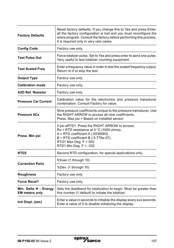
IM-P198-05 MI Issue 2 107
Factory Defaults
Reset factory defaults. If you change this to Yes and press Enter, all the factory configuration is lost and you must reconfigure the entire program. Consult the factory before performing this process, it is required only in very rare cases.
Config Code Factory use only.
Test Pulse Out Force totalizer pulse. Set to Yes and press enter to send one pulse. Very useful to test totalizer counting equipment.
Test Scaled Freq Enter a frequency value in order to test the scaled frequency output. Return to 0 to stop the test.
Output Type Factory use only.
Calibration mode Factory use only.
A2D Ref. Resistor Factory use only.
Pressure Cal Current Calibration value for the electronics and pressure transducer combination. Consult Factory for value.
Pressure 9CsNine pressure coefficients unique to the pressure transducer. Use the RIGHT ARROW to access all nine coefficients.Press. Max psi = Based on installed sensor.
Press. Min psi
0 psi aRTD1. Press the RIGHT ARROW to access:Ro = RTD resistance at 0 °C (1000 ohms).A = RTD coefficient A (.0039083).B = RTD coefficient B (-5.775e-07).RTD1 Max Deg. F = 500RTD1 Min Deg. F = -330
RTD2 Second RTD configuration, for special applications only.
Correction Pairsft3/sec (1 through 10)
%Dev. (1 through 10)
Roughness Factory use only.
Force Recal? Factory use only.
Min. Delta H - Energy EM meters only
Sets the deadband for totalization to begin. Must be greater than this number (1 default) to initiate the totalizer.
Init Displ. (sec) Enter a value in seconds to initialize the display every xxx seconds. Enter a value of 0 to disable initializing the display.
IM-P198-05 MI Issue 2108
6.4 Analogue output calibrationTo check the 4-20 mA circuit, connect a DVM in series with the output loop. Select zero or full scale (from the second column of the hidden diagnostics) and then actuate the enter key twice. This action will cause the meter to output its 4 mA or 20 mA conditions.
If the DVM indicates a current greater than ±0.006 mA from 4 or 20, adjust the setting up or down until the output is calibrated.
Note: these settings are not for adjusting the output zero and span to match a flow range, that function is located in the Output Menu.
6.5 Troubleshooting the flowmeter
Warning!Before attempting any flowmeter repair, verify that the line is not pressurized. Always remove main power before disassembling any part of the mass flowmeter. Use hazardous area precautions if applicable. Static sensitive electronics - use electro-static discharge precautions.
6.6 First check items:- Installation direction correct- Installation depth correct (insertion style meter)- Power and wiring correct- Application fluid correct- Meter range correct for the application- Meter configuration correct- Describe Installation Geometry i.e. upstream diameters, valve position, downstream diameters, etc.
6.7 Record values:Record the following values from the Run menu with the meter installed in order to determine the operating state of the flowmeter:
With Flow With No Flow (if possible)
Flow =
Temperature=
Pressure =
Density =
Error Messages? =

IM-P198-05 MI Issue 2 109
Record the following values from the Hidden Diagnostics Menu with the meter installed:(Use password 16363 to access.)
With Flow With No Flow (if possible)
f =
fi =
A =
A1 =
A2 =
A3 =
A4 =
V =
RTD1 =
RTD2 =
Pe(V) =
Pv(V) =
Ck =
Lvl =
Adj. Filter =
Iso. Power Volts =
Sig. Rev =
Record the following values from the Calibration menu
Vortex Coef Ck =
Low Flow Cutoff =
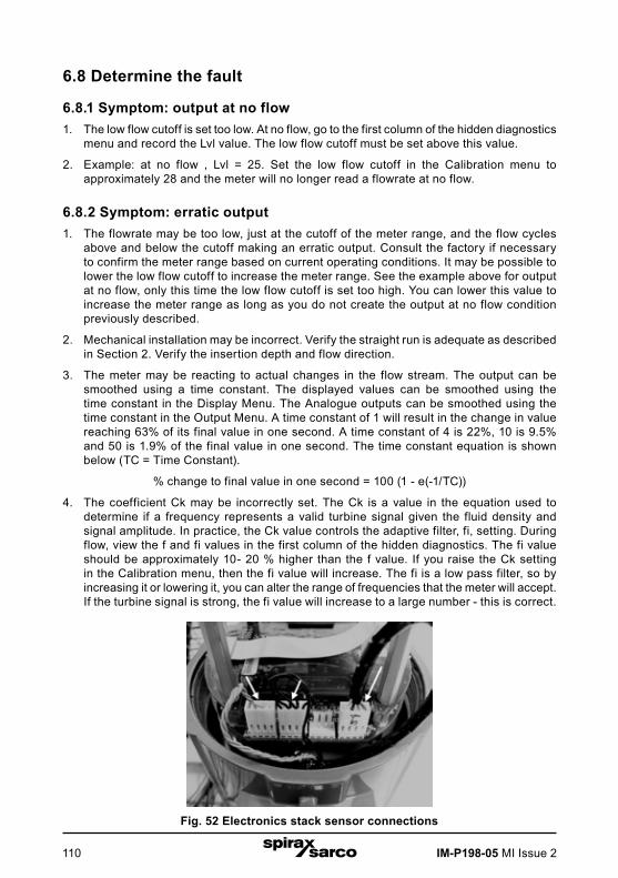
IM-P198-05 MI Issue 2110
6.8 Determine the fault
6.8.1 Symptom: output at no flow1. The low flow cutoff is set too low. At no flow, go to the first column of the hidden diagnostics
menu and record the Lvl value. The low flow cutoff must be set above this value.
2. Example: at no flow , Lvl = 25. Set the low flow cutoff in the Calibration menu to approximately 28 and the meter will no longer read a flowrate at no flow.
6.8.2 Symptom: erratic output1. The flowrate may be too low, just at the cutoff of the meter range, and the flow cycles
above and below the cutoff making an erratic output. Consult the factory if necessary to confirm the meter range based on current operating conditions. It may be possible to lower the low flow cutoff to increase the meter range. See the example above for output at no flow, only this time the low flow cutoff is set too high. You can lower this value to increase the meter range as long as you do not create the output at no flow condition previously described.
2. Mechanical installation may be incorrect. Verify the straight run is adequate as described in Section 2. Verify the insertion depth and flow direction.
3. The meter may be reacting to actual changes in the flow stream. The output can be smoothed using a time constant. The displayed values can be smoothed using the time constant in the Display Menu. The Analogue outputs can be smoothed using the time constant in the Output Menu. A time constant of 1 will result in the change in value reaching 63% of its final value in one second. A time constant of 4 is 22%, 10 is 9.5% and 50 is 1.9% of the final value in one second. The time constant equation is shown below (TC = Time Constant).
% change to final value in one second = 100 (1 - e(-1/TC))
4. The coefficient Ck may be incorrectly set. The Ck is a value in the equation used to determine if a frequency represents a valid turbine signal given the fluid density and signal amplitude. In practice, the Ck value controls the adaptive filter, fi, setting. During flow, view the f and fi values in the first column of the hidden diagnostics. The fi value should be approximately 10- 20 % higher than the f value. If you raise the Ck setting in the Calibration menu, then the fi value will increase. The fi is a low pass filter, so by increasing it or lowering it, you can alter the range of frequencies that the meter will accept. If the turbine signal is strong, the fi value will increase to a large number - this is correct.
Fig. 52 Electronics stack sensor connections
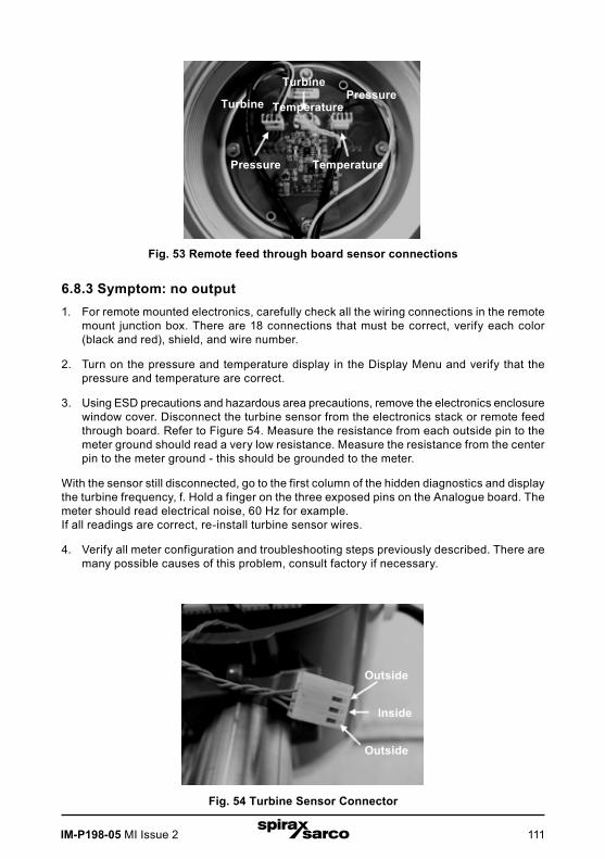
IM-P198-05 MI Issue 2 111
Fig. 53 Remote feed through board sensor connections
6.8.3 Symptom: no output1. For remote mounted electronics, carefully check all the wiring connections in the remote
mount junction box. There are 18 connections that must be correct, verify each color (black and red), shield, and wire number.
2. Turn on the pressure and temperature display in the Display Menu and verify that the pressure and temperature are correct.
3. Using ESD precautions and hazardous area precautions, remove the electronics enclosure window cover. Disconnect the turbine sensor from the electronics stack or remote feed through board. Refer to Figure 54. Measure the resistance from each outside pin to the meter ground should read a very low resistance. Measure the resistance from the center pin to the meter ground - this should be grounded to the meter.
With the sensor still disconnected, go to the first column of the hidden diagnostics and display the turbine frequency, f. Hold a finger on the three exposed pins on the Analogue board. The meter should read electrical noise, 60 Hz for example. If all readings are correct, re-install turbine sensor wires.
4. Verify all meter configuration and troubleshooting steps previously described. There are many possible causes of this problem, consult factory if necessary.
Turbine
Pressure Temperature
TurbinePressure
Temperature
Fig. 54 Turbine Sensor Connector
Outside
Inside
Outside

IM-P198-05 MI Issue 2112
6.8.4 Symptom: meter displays temperature fault1. For remote mounted electronics, carefully check all the wiring connections in the remote
mount junction box. There are 18 connections that must be correct, verify each color (black and red), shield, and wire number.
2. Go to the first column of the hidden diagnostics and check the resistance of the rtd1. It should be about 1080 ohms at room temperature.
3. Using ESD precautions and hazardous area precautions, remove the electronics enclosure window cover. Disconnect the temperature sensor from the electronics stack or the remote feed through board. Refer to Figure 55. Measure the resistance across the outside pins of the temperature sensor connector. It should read approximately 1080 ohms at room temperature (higher resistance at higher temperatures).
4. Consult factory with findings
Fig. 55 Temperature Sensor Connector
Outside
Outside

IM-P198-05 MI Issue 2 113
6.8.5 Symptom: meter displays pressure fault1. For remote mounted electronics, carefully check all the wiring connections in the remote
mount junction box. There are 18 connections that must be correct, verify each color (black and red), shield, and wire number.
2. Using ESD precautions and hazardous area precautions, remove the electronics enclosure window cover. Disconnect the pressure sensor from the electronics stack or the remote feed through board. Measure the resistance across the outside pins of the pressure sensor connector, then across the inside pins. Both readings should be approximately 4000 ohms.
3. Go to the first column of the hidden diagnostics and record the Pe(V) and Pv(V) values and consult the factory with findings.
Fig. 56 Pressure Sensor Connector
Outside
Inside
Outside
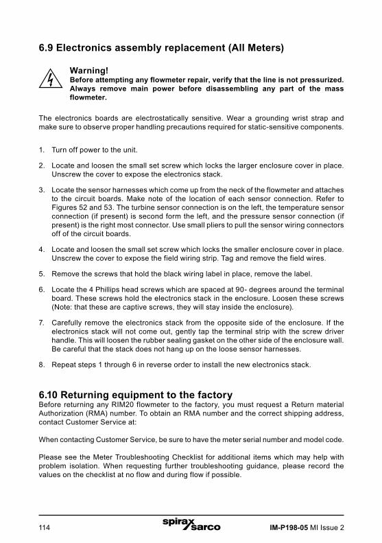
IM-P198-05 MI Issue 2114
6.9 Electronics assembly replacement (All Meters)
Warning! Before attempting any flowmeter repair, verify that the line is not pressurized. Always remove main power before disassembling any part of the mass flowmeter.
The electronics boards are electrostatically sensitive. Wear a grounding wrist strap and make sure to observe proper handling precautions required for static-sensitive components.
1. Turn off power to the unit.
2. Locate and loosen the small set screw which locks the larger enclosure cover in place. Unscrew the cover to expose the electronics stack.
3. Locate the sensor harnesses which come up from the neck of the flowmeter and attaches to the circuit boards. Make note of the location of each sensor connection. Refer to Figures 52 and 53. The turbine sensor connection is on the left, the temperature sensor connection (if present) is second form the left, and the pressure sensor connection (if present) is the right most connector. Use small pliers to pull the sensor wiring connectors off of the circuit boards.
4. Locate and loosen the small set screw which locks the smaller enclosure cover in place. Unscrew the cover to expose the field wiring strip. Tag and remove the field wires.
5. Remove the screws that hold the black wiring label in place, remove the label.
6. Locate the 4 Phillips head screws which are spaced at 90- degrees around the terminal board. These screws hold the electronics stack in the enclosure. Loosen these screws (Note: that these are captive screws, they will stay inside the enclosure).
7. Carefully remove the electronics stack from the opposite side of the enclosure. If the electronics stack will not come out, gently tap the terminal strip with the screw driver handle. This will loosen the rubber sealing gasket on the other side of the enclosure wall. Be careful that the stack does not hang up on the loose sensor harnesses.
8. Repeat steps 1 through 6 in reverse order to install the new electronics stack.
6.10 Returning equipment to the factoryBefore returning any RIM20 flowmeter to the factory, you must request a Return material Authorization (RMA) number. To obtain an RMA number and the correct shipping address, contact Customer Service at:
When contacting Customer Service, be sure to have the meter serial number and model code.
Please see the Meter Troubleshooting Checklist for additional items which may help with problem isolation. When requesting further troubleshooting guidance, please record the values on the checklist at no flow and during flow if possible.
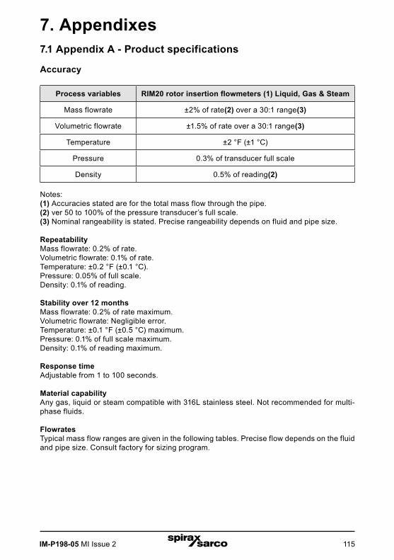
IM-P198-05 MI Issue 2 115
7. Appendixes7.1 Appendix A - Product specifications
Accuracy
Process variables RIM20 rotor insertion flowmeters (1) Liquid, Gas & Steam
Mass flowrate ±2% of rate(2) over a 30:1 range(3)
Volumetric flowrate ±1.5% of rate over a 30:1 range(3)
Temperature ±2 °F (±1 °C)
Pressure 0.3% of transducer full scale
Density 0.5% of reading(2)
Notes: (1) Accuracies stated are for the total mass flow through the pipe.(2) ver 50 to 100% of the pressure transducer’s full scale.(3) Nominal rangeability is stated. Precise rangeability depends on fluid and pipe size.
Repeatability Mass flowrate: 0.2% of rate.Volumetric flowrate: 0.1% of rate. Temperature: ±0.2 °F (±0.1 °C). Pressure: 0.05% of full scale. Density: 0.1% of reading.
Stability over 12 months Mass flowrate: 0.2% of rate maximum.Volumetric flowrate: Negligible error. Temperature: ±0.1 °F (±0.5 °C) maximum. Pressure: 0.1% of full scale maximum. Density: 0.1% of reading maximum.
Response time Adjustable from 1 to 100 seconds.
Material capability Any gas, liquid or steam compatible with 316L stainless steel. Not recommended for multi-phase fluids.
Flowrates Typical mass flow ranges are given in the following tables. Precise flow depends on the fluid and pipe size. Consult factory for sizing program.

IM-P198-05 MI Issue 2116
Typical Metric flowratesSaturated steam (kg / h)
Rotor PressureNominal pipe size
80 mm 150 mm 200 mm 300 mm 400 mm 600 mm
R40
1.4 bar gMinimum 17 72 127 297 491 1 219
Maximum 225 929 1 642 3 817 6 270 15 367
5 bar gMinimum 42 173 306 713 1 176 2 907
Maximum 537 2 216 3 915 9 090 14 905 36 400
10 bar gMinimum 75 310 549 1 279 2 106 5 194
Maximum 962 3 963 6 999 16 239 26 600 64 815
R30
1.4 bar gMinimum 20 82 146 341 563 1 396
Maximum 329 1 358 2 399 5 575 9 149 22 384
5 bar gMinimum 48 198 350 817 1 347 3 328
Maximum 785 3 237 5 716 13 265 21 735 52 993
10 bar gMinimum 86 355 629 1 465 2 411 5 943
Maximum 1 405 5 786 10 215 23 687 38 771 94 337
R20
1.4 bar gMinimum 35 146 259 604 995 2 463
Maximum 530 2 187 3 863 8 968 14 704 35 898
5 bar gMinimum 85 350 620 1 444 2 377 5 856
Maximum 1 265 5 207 9 194 21 322 34 903 84 940
10 bar gMinimum 152 628 1 111 2 586 4 252 10 448
Maximum 2 261 9 303 16 419 38 049 62 227 151 156
R10
1.4 bar gMinimum 61 253 448 1 045 1 721 4 247
Maximum 1 098 4 522 7 985 18 520 30 320 73 805
5 bar gMinimum 147 606 1 072 2 496 4 103 10 082
Maximum 2 615 10 755 18 979 43 967 71 883 174 497
10 bar gMinimum 263 1 087 1 921 4 466 7 335 17 975
Maximum 4 672 19 197 33 862 78 386 128 050 310 382

IM-P198-05 MI Issue 2 117
Typical Metric flowratesSaturated steam (kg / h)
Rotor PressureNominal pipe size
80 mm 150 mm 200 mm 300 mm 400 mm 600 mm
R40
1.4 bar gMinimum 17 72 127 297 491 1 219
Maximum 225 929 1 642 3 817 6 270 15 367
5 bar gMinimum 42 173 306 713 1 176 2 907
Maximum 537 2 216 3 915 9 090 14 905 36 400
10 bar gMinimum 75 310 549 1 279 2 106 5 194
Maximum 962 3 963 6 999 16 239 26 600 64 815
R30
1.4 bar gMinimum 20 82 146 341 563 1 396
Maximum 329 1 358 2 399 5 575 9 149 22 384
5 bar gMinimum 48 198 350 817 1 347 3 328
Maximum 785 3 237 5 716 13 265 21 735 52 993
10 bar gMinimum 86 355 629 1 465 2 411 5 943
Maximum 1 405 5 786 10 215 23 687 38 771 94 337
R20
1.4 bar gMinimum 35 146 259 604 995 2 463
Maximum 530 2 187 3 863 8 968 14 704 35 898
5 bar gMinimum 85 350 620 1 444 2 377 5 856
Maximum 1 265 5 207 9 194 21 322 34 903 84 940
10 bar gMinimum 152 628 1 111 2 586 4 252 10 448
Maximum 2 261 9 303 16 419 38 049 62 227 151 156
R10
1.4 bar gMinimum 61 253 448 1 045 1 721 4 247
Maximum 1 098 4 522 7 985 18 520 30 320 73 805
5 bar gMinimum 147 606 1 072 2 496 4 103 10 082
Maximum 2 615 10 755 18 979 43 967 71 883 174 497
10 bar gMinimum 263 1 087 1 921 4 466 7 335 17 975
Maximum 4 672 19 197 33 862 78 386 128 050 310 382
Typical Metric flowratesAir (nm3 / h) at 20 °C
Rotor PressureNominal pipe size
80 mm 150 mm 200 mm 300 mm 400 mm 600 mm
R40
1.4 bar gMinimum 12 49 87 204 337 838
Maximum 154 639 1 130 2 628 4 320 10 607
5 bar gMinimum 74 305 540 1 259 2 072 5 107
Maximum 946 3 898 6 884 15 969 26 152 63 694
10 bar gMinimum 137 567 1 002 2 332 3 835 9 423
Maximum 1 751 7 205 12 718 29 476 48 216 117 169
R30
1.4 bar gMinimum 14 56 100 234 386 960
Maximum 226 934 1 651 3 839 6 306 15 455
5 bar gMinimum 84 350 619 1 441 2 373 5 844
Maximum 1 382 5 690 10 046 23 290 38 115 92 698
10 bar gMinimum 157 649 1 148 2 671 4 390 10 779
Maximum 2 556 10 511 18 548 42 965 70 237 170 473
R20
1.4 bar gMinimum 24 100 178 415 684 1 696
Maximum 365 1 505 2 660 6 179 10 139 24 794
5 bar gMinimum 150 618 1 094 2 544 4 182 10 271
Maximum 2 224 9 149 16 145 37 407 61 166 148 520
10 bar gMinimum 278 1 146 2 026 4 709 7 731 18 929
Maximum 4 110 16 888 29 789 68 956 112 643 273 032
R10
1.4 bar gMinimum 42 174 308 718 1 184 2 927
Maximum 756 3 115 5 502 12 768 20 919 50 995
5 bar gMinimum 259 1 069 1 890 4 393 7 214 17 668
Maximum 4 595 18 874 33 290 77 048 125 842 304 938
10 bar gMinimum 480 1 980 3 499 8 125 13 323 32 541
Maximum 8 481 34 799 61 349 141 871 231 535 560 318

IM-P198-05 MI Issue 2118
Typical Imperial flowratesSaturated steam (lb / h)
Rotor PressureNominal pipe size
3" 6" 8" 1DN50 (2") 16" 24"
R40
5 psi gMinimum 22 91 162 378 625 1 555
Maximum 287 1 187 2 098 4 883 8 029 19 727
100 psi gMinimum 119 496 878 2 046 3 371 8 328
Maximum 1 540 6 350 11 216 26 034 42 668 104 092
200 psi gMinimum 220 913 1 615 3 761 6 191 15 249
Maximum 2 827 11 643 20 558 47 681 78 064 190 027
R30
5 psi gMinimum 25 105 186 434 717 1 782
Maximum 420 1 735 3 068 7 135 11 721 28 745
100 psi gMinimum 137 568 1 006 2 344 3 861 9 530
Maximum 2 251 9 272 16 373 37 984 62 207 151 526
200 psi gMinimum 253 1 046 1 850 4 308 7 088 17 446
Maximum 4 129 16 994 29 996 69 532 113 761 276 542
R20
5 psi gMinimum 45 186 330 770 1 270 3 150
Maximum 677 2 797 4 943 11 485 18 849 46 119
100 psi gMinimum 243 1 005 1 778 4 140 6 811 16 762
Maximum 3 623 14 915 26 328 61 035 99 870 242 834
200 psi gMinimum 447 1 848 3 268 7 601 12 492 30 657
Maximum 6 643 27 317 48 203 111 658 182 535 443 035
R10
5 psi gMinimum 78 323 572 1 334 2 199 5 440
Maximum 1 405 5 790 10 227 23 736 38 897 94 870
100 psi gMinimum 421 1 739 3 075 7 153 11 755 28 849
Maximum 7 490 30 791 54 325 125 807 205 605 498 759
200 psi gMinimum 774 3 195 5 647 13 123 21 541 52 728
Maximum 13 719 56 341 99 362 229 926 375 467 909 528
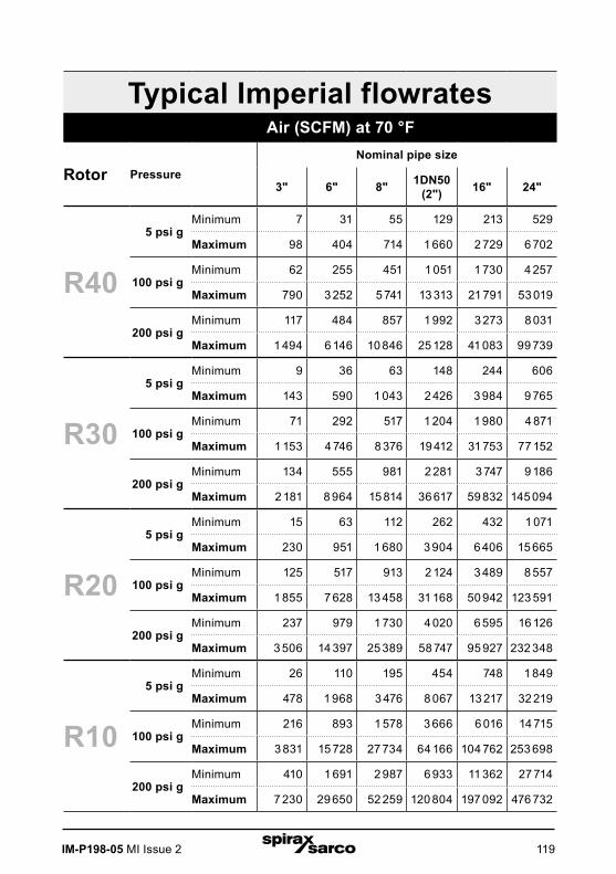
IM-P198-05 MI Issue 2 119
Typical Imperial flowratesAir (SCFM) at 70 °F
Rotor PressureNominal pipe size
3" 6" 8" 1DN50 (2") 16" 24"
R40
5 psi gMinimum 7 31 55 129 213 529
Maximum 98 404 714 1 660 2 729 6 702
100 psi gMinimum 62 255 451 1 051 1 730 4 257
Maximum 790 3 252 5 741 13 313 21 791 53 019
200 psi gMinimum 117 484 857 1 992 3 273 8 031
Maximum 1 494 6 146 10 846 25 128 41 083 99 739
R30
5 psi gMinimum 9 36 63 148 244 606
Maximum 143 590 1 043 2 426 3 984 9 765
100 psi gMinimum 71 292 517 1 204 1 980 4 871
Maximum 1 153 4 746 8 376 19 412 31 753 77 152
200 psi gMinimum 134 555 981 2 281 3 747 9 186
Maximum 2 181 8 964 15 814 36 617 59 832 145 094
R20
5 psi gMinimum 15 63 112 262 432 1 071
Maximum 230 951 1 680 3 904 6 406 15 665
100 psi gMinimum 125 517 913 2 124 3 489 8 557
Maximum 1 855 7 628 13 458 31 168 50 942 123 591
200 psi gMinimum 237 979 1 730 4 020 6 595 16 126
Maximum 3 506 14 397 25 389 58 747 95 927 232 348
R10
5 psi gMinimum 26 110 195 454 748 1 849
Maximum 478 1 968 3 476 8 067 13 217 32 219
100 psi gMinimum 216 893 1 578 3 666 6 016 14 715
Maximum 3 831 15 728 27 734 64 166 104 762 253 698
200 psi gMinimum 410 1 691 2 987 6 933 11 362 27 714
Maximum 7 230 29 650 52 259 120 804 197 092 476 732
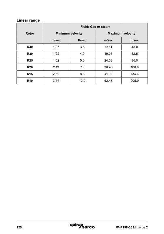
IM-P198-05 MI Issue 2120
Linear range
Rotor
Fluid: Gas or steam
Minimum velocity Maximum velocity
m/sec ft/sec m/sec ft/sec
R40 1.07 3.5 13.11 43.0
R30 1.22 4.0 19.05 62.5
R25 1.52 5.0 24.38 80.0
R20 2.13 7.0 30.48 100.0
R15 2.59 8.5 41.03 134.6
R10 3.66 12.0 62.48 205.0

IM-P198-05 MI Issue 2 121
Process fluid pressureRIM20 Pressure ratings
Probe seal Process connection Material Rating
Compression fitting
2" MNPT 316L SS ANSI 600 lb
2" 150 lb flange, DN50 PN16 316L SS ANSI 150 lb, PN16
2" 300 lb flange, DN50 PN40 316L SS ANSI 300 lb, PN40
2" 600 lb flange, DN50 PN63 316L SS ANSI 600 lb, PN63
Packing gland
2" MNPT 316L SS ANSI 300 lb
2" 150 lb flange, DN50, PN16 316L SS ANSI 150 lb, PN16
2" 300 lb flange, DN50, PN16 316L SS ANSI 300 lb, PN40
Packing gland with permanent retractor
2" MNPT 316L SS ANSI 600 lb
2" 150 lb flange, DN50 PN16 316L SS ANSI 150 lb, PN16
2" 300 lb flange, DN50, PN40 316L SS ANSI 300 lb, PN40
2" 600 lb flange, DN50 PN63 316L SS ANSI 600 lb, PN63

IM-P198-05 MI Issue 2122
Pressure transducer ranges
Pressure sensor ranges(1), bar a (psi a)
Full scale operating pressure Maximum over-range pressure
bar a psi a bar a psi a
2 30 4 60
7 100 14 200
20 300 41 600
34 500 69 1000
100 1500 175 2500
Note: (1) To maximize accuracy, specify the lowest full scale operating pressure range for the application. To avoid damage, the flowmeter must never be subjected to pressure above the over-range pressure shown above.
Power requirements
12 to 36 Vdc, 25 mA, 1 W max., Loop Powered Volumetric or Mass 12 to 36 Vdc, 300 mA, 9 W max. Multiparameter Mass options 100 to 240 Vac, 50/60 Hz, 5 W max. Multiparameter Mass options
Class I Equipment (Grounded Type)
Installation (Over-voltage) Category II for transient over-voltages
AC & dc Mains supply voltage fluctuations are not to exceed +/-10% of the rated supply voltage range.
User is responsible for the provision of an external Disconnect Means (and Over-Current Protection) for the equipment (both ac and dc models).
Display
Alphanumeric 2 x 16 LCD digital display.
Six push-button switches (up, down, right, left, enter, exit) operable through explosion-proof window using hand-held magnet. Viewing at 90-degree mounting intervals.
Process fluid and ambient temperature
Process Fluid: Standard temperature sensor: -55 °C to 232 °C (-67 °F to 450 °F)High Temperature sensor: -267 °C to 454 °C (-448 °F to 850 °F)
Ambient:Operating temperature range: -40 to 60 °C (-40 to 140 °F)
Storage temperature range: -40 to 85 °C (-40 to 185 °F)
Maximum relative humidity: 0-98%, non-condensing conditions
Maximum altitude: 2,000 meters (6,560 feet)
Pollution Degree 2 for the ambient environment
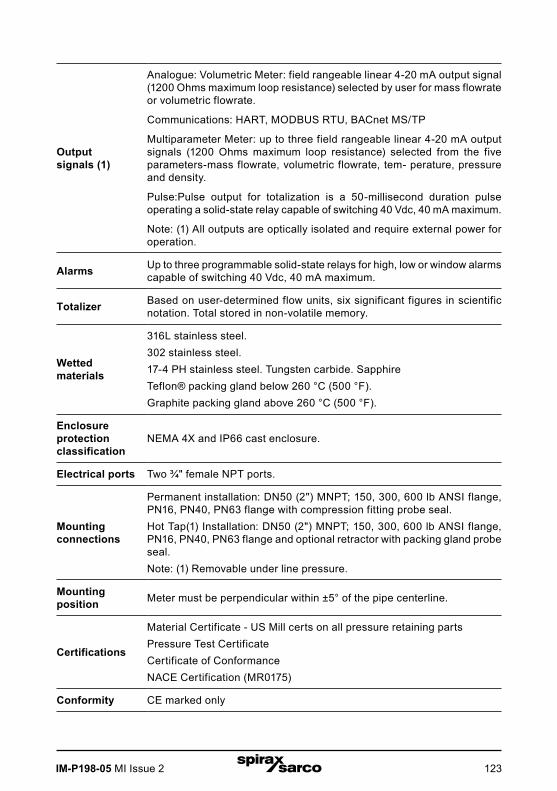
IM-P198-05 MI Issue 2 123
Output signals (1)
Analogue: Volumetric Meter: field rangeable linear 4-20 mA output signal (1200 Ohms maximum loop resistance) selected by user for mass flowrate or volumetric flowrate.
Communications: HART, MODBUS RTU, BACnet MS/TP
Multiparameter Meter: up to three field rangeable linear 4-20 mA output signals (1200 Ohms maximum loop resistance) selected from the five parameters-mass flowrate, volumetric flowrate, tem- perature, pressure and density.
Pulse:Pulse output for totalization is a 50-millisecond duration pulse operating a solid-state relay capable of switching 40 Vdc, 40 mA maximum.
Note: (1) All outputs are optically isolated and require external power for operation.
Alarms Up to three programmable solid-state relays for high, low or window alarms capable of switching 40 Vdc, 40 mA maximum.
Totalizer Based on user-determined flow units, six significant figures in scientific notation. Total stored in non-volatile memory.
Wetted materials
316L stainless steel.302 stainless steel.17-4 PH stainless steel. Tungsten carbide. SapphireTeflon® packing gland below 260 °C (500 °F). Graphite packing gland above 260 °C (500 °F).
Enclosure protection classification
NEMA 4X and IP66 cast enclosure.
Electrical ports Two ¾" female NPT ports.
Mounting connections
Permanent installation: DN50 (2") MNPT; 150, 300, 600 lb ANSI flange, PN16, PN40, PN63 flange with compression fitting probe seal.Hot Tap(1) Installation: DN50 (2") MNPT; 150, 300, 600 lb ANSI flange, PN16, PN40, PN63 flange and optional retractor with packing gland probe seal.Note: (1) Removable under line pressure.
Mounting position Meter must be perpendicular within ±5° of the pipe centerline.
Certifications
Material Certificate - US Mill certs on all pressure retaining partsPressure Test CertificateCertificate of Conformance NACE Certification (MR0175)
Conformity CE marked only

IM-P198-05 MI Issue 2124
7.2 Appendix B Approvals
Low Voltage DirectiveDirective 2014/35/EU
EN 61010-1:2010
Electromagnetic Compatibility DirectiveDirective 2014/30/EU
EN 61000-6-2:2005 EN 55011:2009 + A1:2010 Group 1 Class A

IM-P198-05 MI Issue 2 125
Vf = fKC
Qv = Vf A
QM = Vf A
7.3 Appendix C flowmeter calculations
Flowing velocity
Volume flowrate
Qv = Vf A
Mass flowrate
QM = Vf A r
Where:
A = Cross sectional area of the pipe (ft2)
f = Turbine meter frequency (pulses / sec)
Kc = Meter factor corrected for Reynolds Number (pulses / ft)
Qv = Volume flowrate (ft3 / sec)
QM = Mass flowrate (lbm / sec)
Vf = Flowing velocity (ft / sec)
r = Density (lbm / ft3)

IM-P198-05 MI Issue 2126
Fluid calculations
Calculations for Steam T & PWhen"Steam T & P" is selected in the"Real Gas" selection of the Fluid Menu, the calculations are based on the equations below.
DensityThe density of steam is calculated from the formula given by Keenan and Keys. The given equation is for the volume of the steam.
v = 4.555.04 • T
+ B r
B = B0 + B02 g1 (t) t • r B0
4g2 (t)t3 • r3 - B0
13g3 (t)t12 • r12
B0 = 1.89 - 2641.62 • t • 1080870r2
g1 (t) = 82.546 • t - 1.6246 • 105 • t2
g2 (t) = 0.21828 - 1.2697 • 105 • t2
g3 (t) = 3.635 • 10-4 6.768 • 1064 • t24
Where tau is 1/ temperature in Kelvin.
The density can be found from 1/(v/ standard density of water).
ViscosityThe viscosity is based on an equation given by Keenan and Keys.
h(poise) = 1.501 • 10-5 T
1 + 446.8 / T
Where T is the temperature in Kelvin
v = 4.555.04 • T
+ B
B = B0 + B02 g1 () • B0
4g2 ()3 • 3 - B0
13g3 ()12 • 12
B0 = 1.89 - 2641.62 • • 1080870r2
g1 () = 82.546 • - 1.6246 • 105 • 2
g2 () = 0.21828 - 1.2697 • 105 • 2
g3 () = 3.635 • 10-4 6.768 • 1064 • 24
(poise) = 1.501 • 10-5 T
1 + 446.8 / T
v = 4.555.04 • T
+ B
B = B0 + B02 g1 () • B0
4g2 ()3 • 3 - B0
13g3 ()12 • 12
B0 = 1.89 - 2641.62 • • 1080870r2
g1 () = 82.546 • - 1.6246 • 105 • 2
g2 () = 0.21828 - 1.2697 • 105 • 2
g3 () = 3.635 • 10-4 6.768 • 1064 • 24
(poise) = 1.501 • 10-5 T
1 + 446.8 / T

IM-P198-05 MI Issue 2 127
= GMw, Air Pf
Zf R0 Tf
cP = aTKn
n = 1n [(cP)2 / (cP)1]
1n(TK2 / TK1)
a = (cP)1
TK1n
Calculations for Gas ("Real Gas" and"Other Gas")Use this formula to determine the settings for"Real Gas; Gas" selections and"Other Gas" selections entered in the Fluid Menu. The calculations for gas were taken from Richard W. Miller, Flow Measurement Engineering Handbook (Third Edition, 1996).
DensityThe density for real gases is calculated from the equation:
r = GMw, Air Pf
Zf R0 Tf
Where G is the specific gravity, Mw is the molecular weight of air, pf is the flowing pressure, Z is flowing compressibility, R0 is the universal gas constant, and T is the flowing temperature.The specific gravity, and R0 are known and are stored in a table used by the Turbine meter.The hard coefficient to find is the compressibility, Z. Z is found using the Redlich-Kwong Equation (Miller page 2-18).
The Redlich-Kwong Equation uses the reduced temperature and pressure to calculate the compressibility factor. The equations are non linear and an iterative solution is used. The Turbine program uses Newton's Method on the Redlich-Kwong equations to iteratively find the compressibility factor. The critical temperature and pressure used in the Redlich- Kwong equation are stored in the fluid data table with the other coefficients.
ViscosityThe viscosity for real gases is calculated using the exponential equation for two known viscosities. The equation is:
mcP = aTKn
Where a and n are found from two known viscosities at two temperatures.
n = 1n [(mcP)2 / (mcP)1]
1n(TK2 / TK1)
and
a = (mcP)1
TK1n
= GMw, Air Pf
Zf R0 Tf
cP = aTKn
n = 1n [(cP)2 / (cP)1]
1n(TK2 / TK1)
a = (cP)1
TK1n
= GMw, Air Pf
Zf R0 Tf
cP = aTKn
n = 1n [(cP)2 / (cP)1]
1n(TK2 / TK1)
a = (cP)1
TK1n
= GMw, Air Pf
Zf R0 Tf
cP = aTKn
n = 1n [(cP)2 / (cP)1]
1n(TK2 / TK1)
a = (cP)1
TK1n
= GMw, Air Pf
Zf R0 Tf
cP = aTKn
n = 1n [(cP)2 / (cP)1]
1n(TK2 / TK1)
a = (cP)1
TK1n
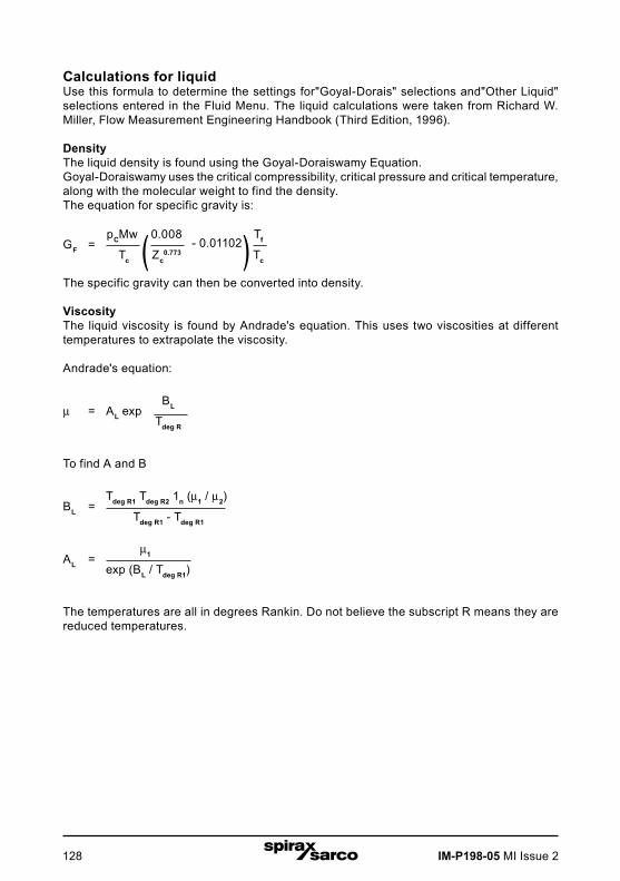
IM-P198-05 MI Issue 2128
Calculations for liquidUse this formula to determine the settings for"Goyal-Dorais" selections and"Other Liquid" selections entered in the Fluid Menu. The liquid calculations were taken from Richard W. Miller, Flow Measurement Engineering Handbook (Third Edition, 1996).
DensityThe liquid density is found using the Goyal-Doraiswamy Equation.Goyal-Doraiswamy uses the critical compressibility, critical pressure and critical temperature, along with the molecular weight to find the density.The equation for specific gravity is:
GF = pCMw 0.008
- 0.01102 Tf
Tc Zc0.773 Tc
The specific gravity can then be converted into density.
ViscosityThe liquid viscosity is found by Andrade's equation. This uses two viscosities at different temperatures to extrapolate the viscosity.
Andrade's equation:
m = AL exp BL
Tdeg R
To find A and B
BL = Tdeg R1 Tdeg R2 1n (m1 / m2)
Tdeg R1 - Tdeg R1
AL = m1
exp (BL / Tdeg R1)
The temperatures are all in degrees Rankin. Do not believe the subscript R means they are reduced temperatures.
GF = pCMw 0.008
- 0.01102 Tf
Tc Zc0.773 Tc
= AL exp BL
Tdeg R
BL = Tdeg R1 Tdeg R2 1n (1 / 2)
Tdeg R1 - Tdeg R1
AL = 1
exp (BL / Tdeg R1)
( )GF = pCMw 0.008
- 0.01102 Tf
Tc Zc0.773 Tc
= AL exp BL
Tdeg R
BL = Tdeg R1 Tdeg R2 1n (1 / 2)
Tdeg R1 - Tdeg R1
AL = 1
exp (BL / Tdeg R1)
( )GF = pCMw 0.008
- 0.01102 Tf
Tc Zc0.773 Tc
= AL exp BL
Tdeg R
BL = Tdeg R1 Tdeg R2 1n (1 / 2)
Tdeg R1 - Tdeg R1
AL = 1
exp (BL / Tdeg R1)
( )

IM-P198-05 MI Issue 2 129
7.4 Appendix D Glossary
A
A Cross sectional area.
ACFM Actual Cubic Feet Per Minute (volumetric flowrate).
ASME American Society of Mechanical Engineers.
B BTU British Thermal Unit, an energy measurement.
C
Cenelec European Electrical Code.
Compressibility factor
A factor used to correct for the non-ideal changes in a fluid ís density due to changes in temperature and/or pressure.
CSA Canadian Standards Association.
D D Diameter of a flow channel.
F
f Frequency generated by a turbine flowmeter, usually in Hz.
Flow channel A pipe, duct, stack, or channel containing flowing fluid.
Flow profile A map of the fluid velocity vector (usually non- uniform) in a cross-sectional plane of a flow channel (usually along a diameter).
FM Factory Mutual.
Ft Foot, 1 DN50 (2"), a measure of length.
Ft2 Square feet, measure of area.
Ft3 Cubic feet, measure of volume.
G GPM Gallons Per Minute.
H Hz Hertz, cycles per second.
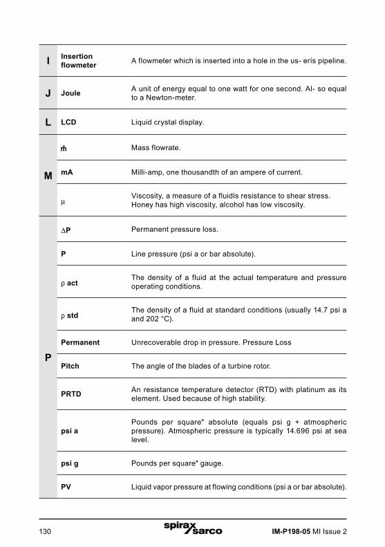
IM-P198-05 MI Issue 2130
I Insertion flowmeter A flowmeter which is inserted into a hole in the us- erís pipeline.
J Joule A unit of energy equal to one watt for one second. Al- so equal to a Newton-meter.
L LCD Liquid crystal display.
M
Mass flowrate.
mA Milli-amp, one thousandth of an ampere of current.
mViscosity, a measure of a fluidís resistance to shear stress.Honey has high viscosity, alcohol has low viscosity.
P
P Permanent pressure loss.
P Line pressure (psi a or bar absolute).
r actThe density of a fluid at the actual temperature and pressure operating conditions.
r stdThe density of a fluid at standard conditions (usually 14.7 psi a and 202 °C).
Permanent Unrecoverable drop in pressure. Pressure Loss
Pitch The angle of the blades of a turbine rotor.
PRTD An resistance temperature detector (RTD) with platinum as its element. Used because of high stability.
psi aPounds per square" absolute (equals psi g + atmospheric pressure). Atmospheric pressure is typically 14.696 psi at sea level.
psi g Pounds per square" gauge.
PV Liquid vapor pressure at flowing conditions (psi a or bar absolute).

IM-P198-05 MI Issue 2 131
Q Q Flowrate, usually volumetric.
R
Rangeability Highest measurable flowrate divided by the lowest measurable flowrate.
Reynolds number
A dimensionless number equal to the density of a fluid or Retimes the velocity of the fluid times the diameter of the fluid channel, divided by the fluid viscosity (i.e., Re = rVD/m). The Reynolds number is an important num- ber for turbine flowmeters because it is used to determine the minimum measurable flowrate. It is the ratio of the inertial forces to the viscous forces in a flowing fluid.
Rotor
The velocity sensing element of a turbine flowmeter.Rotors are manufactured with the blades at a certain pitch. The pitch of the rotor blades determine the maximum velocity the turbine flowmeter can be used in.
RTD Resistance temperature detector, a sensor whose resistance increases as the temperature rises.
S scfm Standard cubic feet per minute (flowrate converted to standard conditions, usually 14.696 psi a and 682 F).
TTotalizer An electronic counter which records the total accumulated flow
over a certain range of time.
Traverse The act of moving a measuring point across the width of a flow channel.
U Uncertainty The closeness of agreement between the result of a measurement and the true value of the measurement.
V
V Velocity or voltage.
Vac Volts, alternating current.
Vdc Volts, direct current.

IM-P198-05 MI Issue 2132


![User's AXF Manual Magnetic Flowmeter Integral Flowmeter ... · Magnetic Flowmeter Integral Flowmeter/ Remote Flowtube [Hardware Edition] IM 01E20D01-01E IM 01E20D01-01E 7th Edition](https://img.pdfslide.us/doc/110x75/5e9c29fa54300501b21ae83a/users-axf-manual-magnetic-flowmeter-integral-flowmeter-magnetic-flowmeter-integral.jpg)


![User's AXF Manual Magnetic Flowmeter Integral Flowmeter ... · User's Manual Yo kogawa Electric Corporation AXF Magnetic Flowmeter Integral Flowmeter/ Remote Flowtube [Hardware Edition]](https://img.pdfslide.us/doc/110x75/5c40f15893f3c338c3289cbb/users-axf-manual-magnetic-flowmeter-integral-flowmeter-users-manual-yo.jpg)


![AXR Two-wire Magnetic Flowmeter Integral Flowmeter [Style:S2]](https://img.pdfslide.us/doc/110x75/62cb14e07ee31d38b74d3e5b/axr-two-wire-magnetic-flowmeter-integral-flowmeter-styles2.jpg)