Embed Size (px)
Citation preview
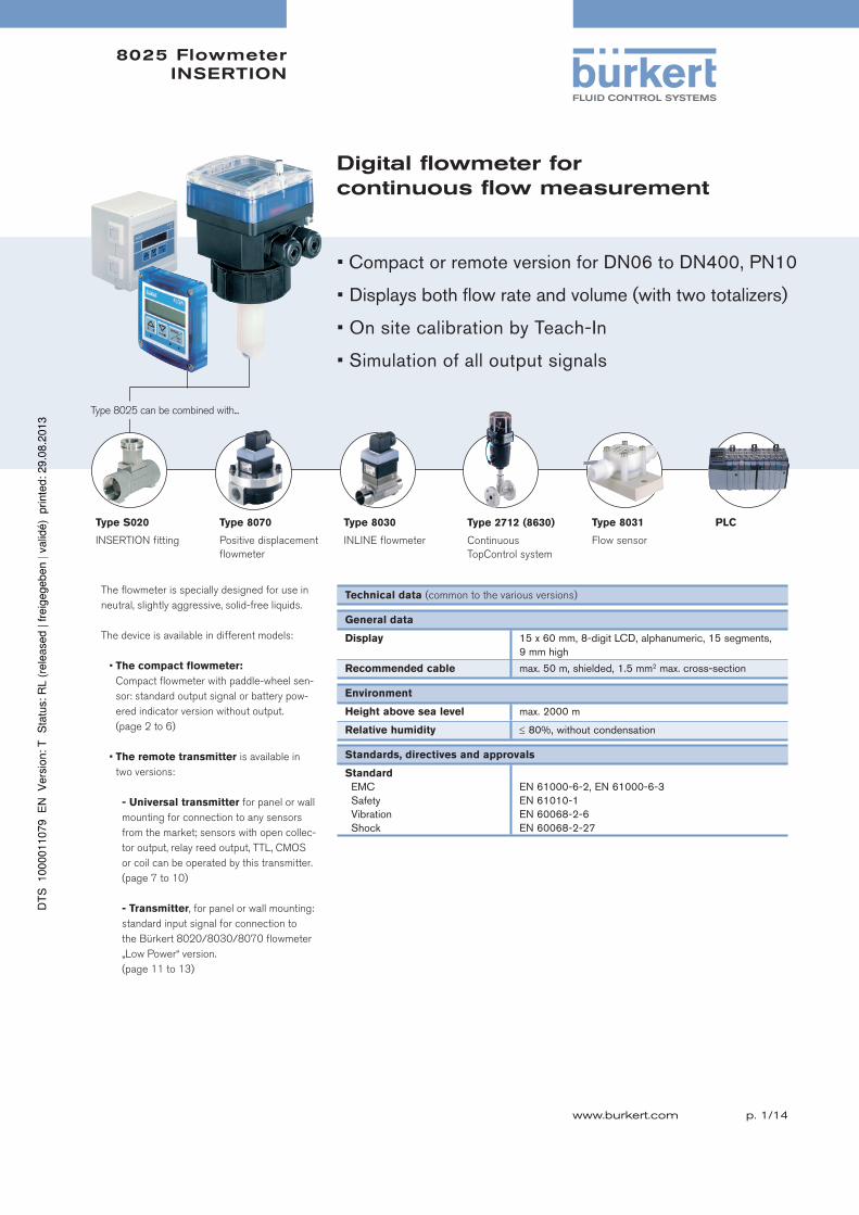
8025 Flowmeter INSERTION
p. 1/14www.burkert.com
Type 8031
Flow sensor
Digital flowmeter forcontinuous flow measurement
The flowmeter is specially designed for use in
neutral, slightly aggressive, solid-free liquids.
The device is available in different models:
• The compact flowmeter:
Compact flowmeter with paddle-wheel sen-
sor: standard output signal or battery pow-
ered indicator version without output.
(page 2 to 6)
• The remote transmitter is available in
two versions:
- Universal transmitter for panel or wall
mounting for connection to any sensors
from the market; sensors with open collec-
tor output, relay reed output, TTL, CMOS
or coil can be operated by this transmitter.
(page 7 to 10)
- Transmitter, for panel or wall mounting:
standard input signal for connection to
the Bürkert 8020/8030/8070 flowmeter
„Low Power“ version.
(page 11 to 13)
Technical data (common to the various versions)
General data
Display 15 x 60 mm, 8-digit LCD, alphanumeric, 15 segments, 9 mm high
Recommended cable max. 50 m, shielded, 1.5 mm2 max. cross-section
Environment
Height above sea level max. 2000 m
Relative humidity 80%, without condensation
Standards, directives and approvals
Standard EMC
SafetyVibrationShock
EN 61000-6-2, EN 61000-6-3EN 61010-1EN 60068-2-6EN 60068-2-27
Type S020
INSERTION fitting
Type 8070
Positive displacement
flowmeter
Type 8030
INLINE flowmeter
• Compact or remote version for DN06 to DN400, PN10
• Displays both flow rate and volume (with two totalizers)
• On site calibration by Teach-In
• Simulation of all output signals
Type 8025 can be combined with...
Type 2712 (8630)
Continuous
TopControl system
PLC
8025 FlowmeterINSERTION COMPACT
p. 2/14
The compact version
Technical data
General data
Compatibility with fittings S020 (see corresponding data sheet)
Materials
Housing, cover, lid, nutFront panel foil / ScrewsCable plug or glandsWetted parts materials
FittingSensor holder, paddle-wheelAxis and bearing / Seal
PCPolyester / Stainless steelPA
Brass, stainless steel 1.4404/316L, PVC, PP or PVDFPVDFCeramics / FKM (EPDM option)
Electrical connections Cable plug or cable glands M20 x 1.5 or none (for battery
version).
Device data (Fitting S020 + flowmeter)
Pipe diameter DN20 to DN400
Measuring range 0.5 to 10 m/s (Battery version - Coil transducer)
0.3 to 10 m/s (Hall transducer version)
Fluid temperature with fitting in
PVC / PPPVDF, brass or stainless steel
0 to 50°C (32 to 122°F) / 0 to 80°C (32 to 176°F)
-15 to 80°C1) (5 to 176°F)
Fluid pressure max. PN10 (145.1 PSI) (see pressure/temperature diagram on page 4)
Viscosity / Pollution 300 cSt. max. / 1% max.
Accuracy
Teach-InStandard K-factor
±0.5% of F.S.*2)
±(0.5% of F.S.* + 2.5% of Reading)2)
Linearity ±0.5% of F.S.*2)
Repeatability 0.4% of Reading2)
Electrical data
Power supply (V+)
Standard signal version
Battery indicator/totalizer version
12 - 36 V DC ±10%, filtered and regulated, SELV (safety ex-
tra low voltage) circuit with a non dangerous energy level or115/230 V AC 50/60 Hz (see technical specifications 115/230 V AC)
2 x 9 V DC batteries, lifetime min. 1 year at 20°C (68°F)
Reversed polarity of DC protected
Current consumption with sensor
(without consumption of pulse output)
70 mA at 12 V DC - flowmeter with relays 25 mA at 12 V DC - flowmeter without relay
Output
Standard signal version Signal current
Pulse
Relay Battery indicator/totalizer version
4... 20 mA (3-wire with relays; 2-wire without relay)
max. loop impedance: 900 at 30 V DC,600 at 24 V DC, 50 at 12 V DC,800 with a 115/230 V AC voltage supplyPolarized, potential free, 5... 36 V DC; 100 mA,protected, line drop at 100 mA: 2.5 V DC2 relays, freely configurable, 3 A, 230 V ACNone
Environment
Ambient temperature
(operation and storage)
-10 to +60°C (32 to 140°F) (version 12 - 36 V DC)
-10 to +50°C (32 to 122°F) (version 115/230 V AC)
Technical specifications 115/230 V AC
Voltage supply
available inside the device27 V DC regulated, max. current: 125 mAintegrated protection: fuse 125 mA temporisedpower: 3 VA
Standards, directives and approvals
Protection class
(according to EN60529)
IP65 with cable plug or gland mounted and tightened or with obturator locked if not used.
Standards and directives
Pressure Complying with article 3 of chap. 3 from 97/23/CE directive*
* F.S.=Full scale (10 m/s) 1) with Battery version = 100°C (212°F)2) Under reference conditions i.e. measuring fluid=water, ambient and water temperature=20°C (68°F), applying the mini-mum inlet and outlet pipe straights, matched inside pipe dimensions.
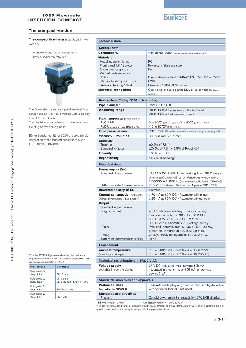
The compact flowmeter is available in two
versions:
- standard signal (4... 20 mA, frequency)
- battery indicator/totalizer
The flowmeter combines a paddle-wheel flow
sensor and an electronic module with a display
in an IP65 enclosure.
The electrical connection is provided via a ca-
ble plug or two cable glands.
Bürkert designed fitting S020 ensures simple
installation of the Bürkert sensor into pipes
from DN20 to DN400
* For the 97/23/CE pressure directive, the device can only be used under following conditions (depend on max. pressure, pipe diameter and fluid).
Type of fluid Conditions
Fluid group 1, chap. 1.3.a DN25 only
Fluid group 2, chap. 1.3.a
DN 32, orDN > 32 and PN*DN 1000
Fluid group 1, chap. 1.3.b PN*DN 2000
Fluid group 2, chap. 1.3.b DN 200
8025 FlowmeterINSERTION COMPACT
p. 3/14
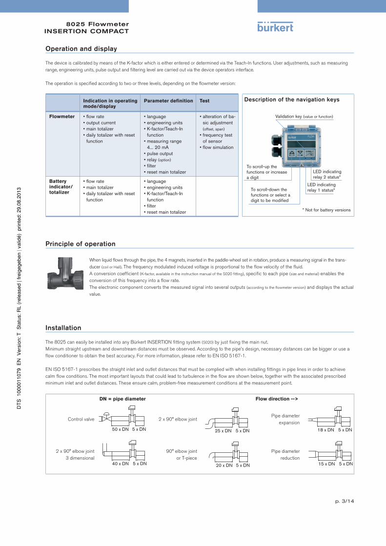
Operation and display
The device is calibrated by means of the K-factor which is either entered or determined via the Teach-In functions. User adjustments, such as measuring
range, engineering units, pulse output and filtering level are carried out via the device operators interface.
The operation is specified according to two or three levels, depending on the flowmeter version:
Indication in operating
mode/display
Parameter definition Test Description of the navigation keys
Validation key (value or function)
To scroll-up the functions or increase a digit
To scroll-down the functions or select a digit to be modified
LED indicating relay 2 status*
* Not for battery versions
LED indicating relay 1 status*
Flowmeter • flow rate• output current• main totalizer• daily totalizer with reset
function
• language• engineering units• K-factor/Teach-In
function• measuring range
4... 20 mA• pulse output• relay (option)
• filter • reset main totalizer
• alteration of ba-sic adjustment (offset, span)
• frequency test of sensor
• flow simulation
Battery
indicator/
totalizer
• flow rate• main totalizer• daily totalizer with reset
function
• language• engineering units• K-factor/Teach-In
function• filter • reset main totalizer
Principle of operation
When liquid flows through the pipe, the 4 magnets, inserted in the paddle-wheel set in rotation, produce a measuring signal in the trans-
ducer (coil or Hall). The frequency modulated induced voltage is proportional to the flow velocity of the fluid.
A conversion coefficient (K-factor, available in the instruction manual of the S020 fitting), specific to each pipe (size and material) enables the
conversion of this frequency into a flow rate.
The electronic component converts the measured signal into several outputs (according to the flowmeter version) and displays the actual
value.
Installation
The 8025 can easily be installed into any Bürkert INSERTION fitting system (S020) by just fixing the main nut.
Minimum straight upstream and downstream distances must be observed. According to the pipe’s design, necessary distances can be bigger or use a
flow conditioner to obtain the best accuracy. For more information, please refer to EN ISO 5167-1.
EN ISO 5167-1 prescribes the straight inlet and outlet distances that must be complied with when installing fittings in pipe lines in order to achieve
calm flow conditions. The most important layouts that could lead to turbulence in the flow are shown below, together with the associated prescribed
minimum inlet and outlet distances. These ensure calm, problem-free measurement conditions at the measurement point.
DN = pipe diameter Flow direction -->
Control valve 2 x 90° elbow jointPipe diameter
expansion
2 x 90° elbow joint
3 dimensional
90° elbow joint
or T-piece
Pipe diameter
reduction
8025 FlowmeterINSERTION COMPACT
p. 4/14
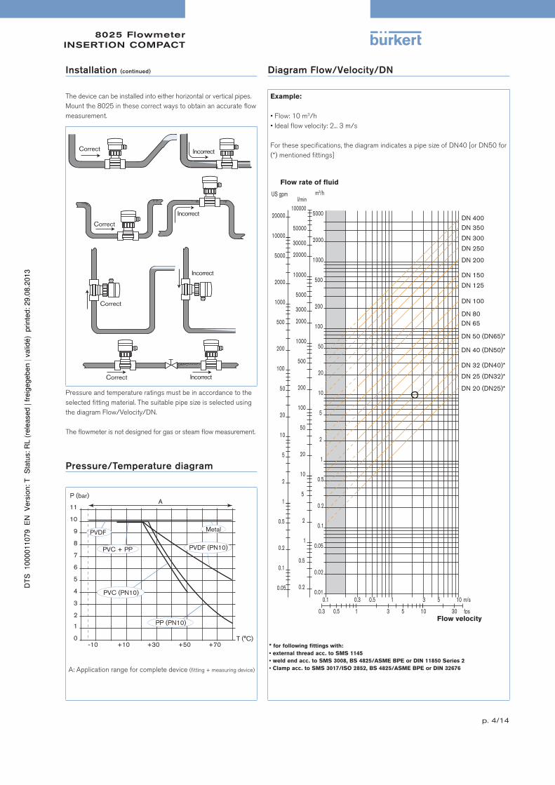
Installation (continued) Diagram Flow/Velocity/DN
The device can be installed into either horizontal or vertical pipes.
Mount the 8025 in these correct ways to obtain an accurate flow
measurement.
Example:
• Flow: 10 m3/h
• Ideal flow velocity: 2... 3 m/s
For these specifications, the diagram indicates a pipe size of DN40 [or DN50 for
(*) mentioned fittings]Correct
Correct
Correct
Correct
Incorrect
Incorrect
Incorrect
Incorrect
Flow rate of fluid
Flow velocity
0.1 0.3 0.5 1 3 5 10 0.01
0.02
0.05
0.1
0.2
0.5
1
2
5
10
20
50
100
200
m 3 /h
0.2
0.5
1
2
5
10
20
50
100
200
500
1000
2000
3000
l/min
0.3 0.5 1 3 5 10 30
m/s
fps
US gpm
0.05
0.1
0.2
0.5
1
2
5
10
20
50
100
200
500
1000
DN 65
DN 50 (DN65)*
DN 40 (DN50)*
DN 32 (DN40)*
DN 25 (DN32)*
DN 20 (DN25)*
500
1000
2000
2000
5000
10000
5000 20000
5000
10000
20000
30000
50000
100000
DN 400
DN 350
DN 300
DN 250
DN 200
DN 150
DN 125
DN 100
DN 80
Pressure and temperature ratings must be in accordance to the
selected fitting material. The suitable pipe size is selected using
the diagram Flow/Velocity/DN.
The flowmeter is not designed for gas or steam flow measurement.
Pressure/Temperature diagram
A: Application range for complete device (fitting + measuring device)
P (bar)
PVDF
PVC + PP PVDF (PN10)
PVC (PN10)
PP (PN10)
Metal
* for following fittings with:
• external thread acc. to SMS 1145
• weld end acc. to SMS 3008, BS 4825/ASME BPE or DIN 11850 Series 2
• Clamp acc. to SMS 3017/ISO 2852, BS 4825/ASME BPE or DIN 32676
8025 FlowmeterINSERTION COMPACT
p. 5/14
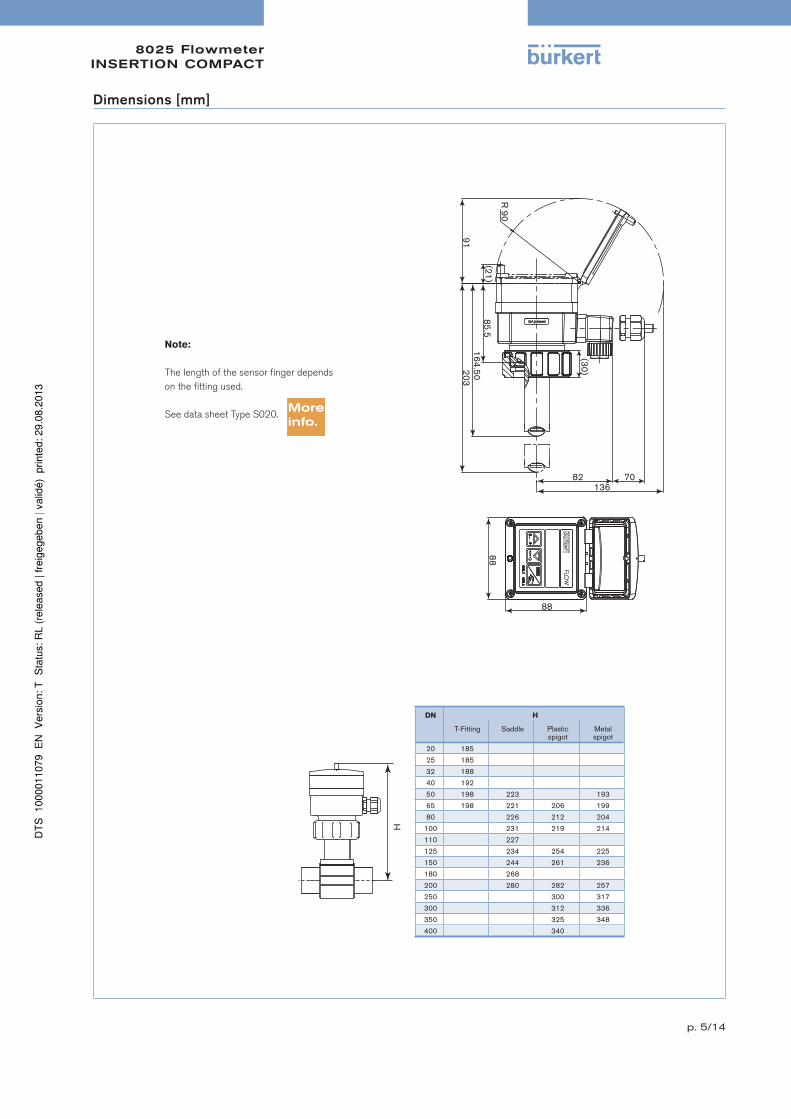
Dimensions [mm]
Note:
The length of the sensor finger depends
on the fitting used.
See data sheet Type S020.
DN H
T-Fitting Saddle Plastic spigot
Metal spigot
20 185
25 185
32 188
40 192
50 198 223 193
65 198 221 206 199
80 226 212 204
100 231 219 214
110 227
125 234 254 225
150 244 261 236
180 268
200 280 282 257
250 300 317
300 312 336
350 325 348
400 340
8025 FlowmeterINSERTION COMPACT
p. 6/14
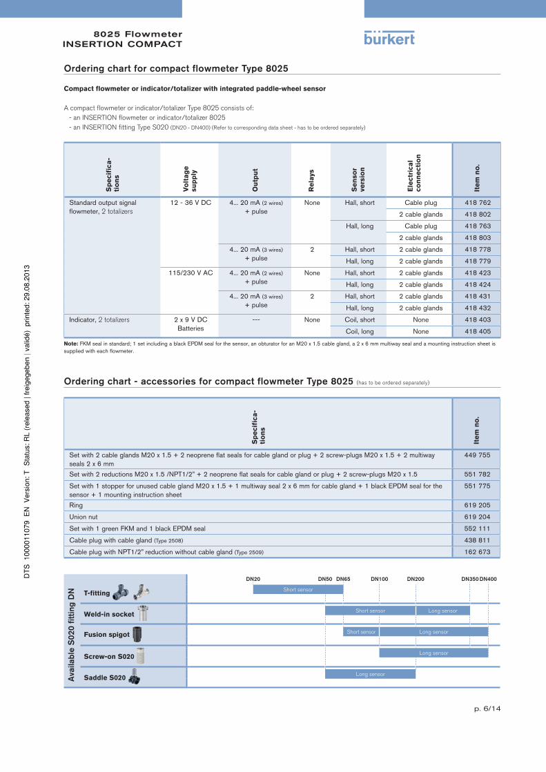
Ordering chart for compact flowmeter Type 8025
Compact flowmeter or indicator/totalizer with integrated paddle-wheel sensor
A compact flowmeter or indicator/totalizer Type 8025 consists of:
- an INSERTION flowmeter or indicator/totalizer 8025
- an INSERTION fitting Type S020 (DN20 - DN400) (Refer to corresponding data sheet - has to be ordered separately)
Sp
ecif
ica
-
tio
ns
Vo
lta
ge
su
pp
ly
Ou
tpu
t
Re
lays
Se
nso
r
ve
rsio
n
Ele
ctr
ica
l
co
nn
ecti
on
Ite
m n
o.
Standard output signalflowmeter, 2 totalizers
12 - 36 V DC 4... 20 mA (2 wires)
+ pulseNone Hall, short Cable plug 418 762
2 cable glands 418 802
Hall, long Cable plug 418 763
2 cable glands 418 803
4... 20 mA (3 wires)
+ pulse2 Hall, short 2 cable glands 418 778
Hall, long 2 cable glands 418 779
115/230 V AC 4... 20 mA (2 wires)
+ pulseNone Hall, short 2 cable glands 418 423
Hall, long 2 cable glands 418 424
4... 20 mA (3 wires)
+ pulse2 Hall, short 2 cable glands 418 431
Hall, long 2 cable glands 418 432
Indicator, 2 totalizers 2 x 9 V DCBatteries
--- None Coil, short None 418 403
Coil, long None 418 405
Note: FKM seal in standard; 1 set including a black EPDM seal for the sensor, an obturator for an M20 x 1.5 cable gland, a 2 x 6 mm multiway seal and a mounting instruction sheet is supplied with each flowmeter.
Ordering chart - accessories for compact flowmeter Type 8025 (has to be ordered separately)
Sp
ecif
ica
-
tio
ns
Ite
m n
o.
Set with 2 cable glands M20 x 1.5 + 2 neoprene flat seals for cable gland or plug + 2 screw-plugs M20 x 1.5 + 2 multiway seals 2 x 6 mm
449 755
Set with 2 reductions M20 x 1.5 /NPT1/2” + 2 neoprene flat seals for cable gland or plug + 2 screw-plugs M20 x 1.5 551 782
Set with 1 stopper for unused cable gland M20 x 1.5 + 1 multiway seal 2 x 6 mm for cable gland + 1 black EPDM seal for the sensor + 1 mounting instruction sheet
551 775
Ring 619 205
Union nut 619 204
Set with 1 green FKM and 1 black EPDM seal 552 111
Cable plug with cable gland (Type 2508) 438 811
Cable plug with NPT1/2” reduction without cable gland (Type 2509) 162 673
DN20 DN50 DN65 DN100 DN200 DN350 DN400
Availab
le S
020 f
itting
DN T-fitting
Short sensor
Weld-in socket
Short sensor Long sensor
Fusion spigot
Short sensor Long sensor
Screw-on S020 Long sensor
Saddle S020
Long sensor
8025 TransmitterREMOTE UNIVERSAL
p. 7/14
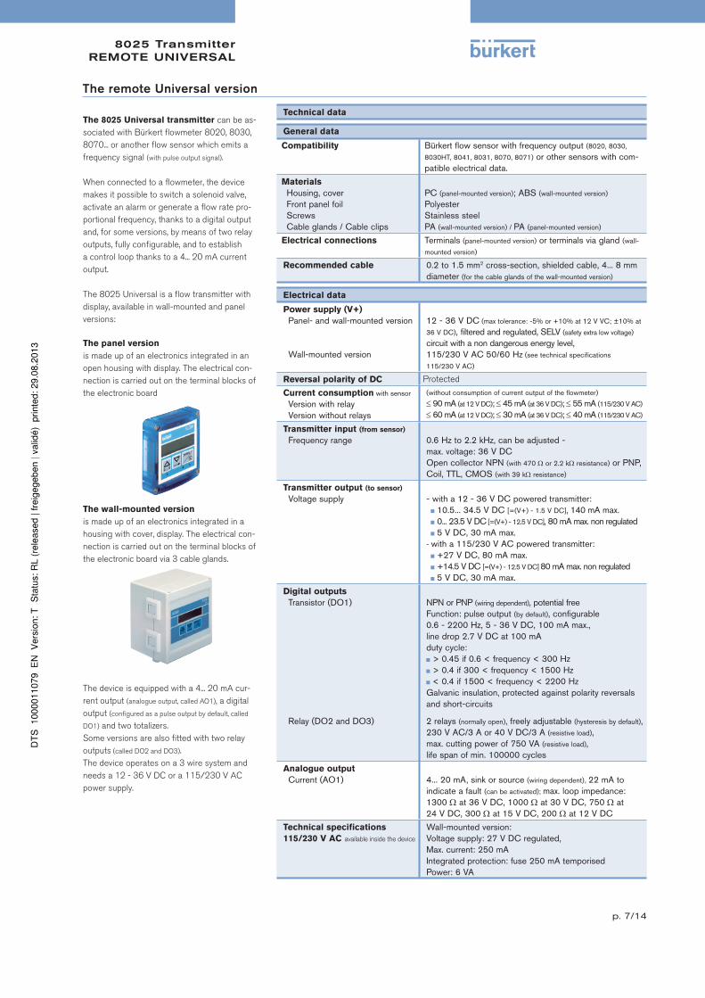
The remote Universal version
The 8025 Universal transmitter can be as-
sociated with Bürkert flowmeter 8020, 8030,
8070... or another flow sensor which emits a
frequency signal (with pulse output signal).
When connected to a flowmeter, the device
makes it possible to switch a solenoid valve,
activate an alarm or generate a flow rate pro-
portional frequency, thanks to a digital output
and, for some versions, by means of two relay
outputs, fully configurable, and to establish
a control loop thanks to a 4... 20 mA current
output.
The 8025 Universal is a flow transmitter with
display, available in wall-mounted and panel
versions:
The panel version
is made up of an electronics integrated in an
open housing with display. The electrical con-
nection is carried out on the terminal blocks of
the electronic board
The wall-mounted version
is made up of an electronics integrated in a
housing with cover, display. The electrical con-
nection is carried out on the terminal blocks of
the electronic board via 3 cable glands.
The device is equipped with a 4... 20 mA cur-
rent output (analogue output, called AO1), a digital
output (configured as a pulse output by default, called
DO1) and two totalizers.
Some versions are also fitted with two relay
outputs (called DO2 and DO3).
The device operates on a 3 wire system and
needs a 12 - 36 V DC or a 115/230 V AC
power supply.
Technical data
General data
Compatibility Bürkert flow sensor with frequency output (8020, 8030,
8030HT, 8041, 8031, 8070, 8071) or other sensors with com-patible electrical data.
Materials
Housing, coverFront panel foilScrewsCable glands / Cable clips
PC (panel-mounted version); ABS (wall-mounted version)
PolyesterStainless steelPA (wall-mounted version) / PA (panel-mounted version)
Electrical connections Terminals (panel-mounted version) or terminals via gland (wall-
mounted version)
Recommended cable 0.2 to 1.5 mm2 cross-section, shielded cable, 4... 8 mm diameter (for the cable glands of the wall-mounted version)
Electrical data
Power supply (V+)
Panel- and wall-mounted version
Wall-mounted version
12 - 36 V DC (max tolerance: -5% or +10% at 12 V VC; ±10% at
36 V DC), filtered and regulated, SELV (safety extra low voltage) circuit with a non dangerous energy level,115/230 V AC 50/60 Hz (see technical specifications
115/230 V AC)
Reversal polarity of DC Protected
Current consumption with sensor
Version with relayVersion without relays
(without consumption of current output of the flowmeter)
90 mA (at 12 V DC); 45 mA (at 36 V DC); 55 mA (115/230 V AC)
60 mA (at 12 V DC); 30 mA (at 36 V DC); 40 mA (115/230 V AC)
Transmitter input (from sensor)
Frequency range 0.6 Hz to 2.2 kHz, can be adjusted -max. voltage: 36 V DCOpen collector NPN (with 470 or 2.2 k resistance) or PNP, Coil, TTL, CMOS (with 39 k resistance)
Transmitter output (to sensor)
Voltage supply - with a 12 - 36 V DC powered transmitter: 10.5... 34.5 V DC [=(V+) - 1.5 V DC], 140 mA max.
0... 23.5 V DC [=(V+) - 12.5 V DC], 80 mA max. non regulated 5 V DC, 30 mA max.
- with a 115/230 V AC powered transmitter: +27 V DC, 80 mA max.
+14.5 V DC [=(V+) - 12.5 V DC] 80 mA max. non regulated 5 V DC, 30 mA max.
Digital outputs
Transistor (DO1)
Relay (DO2 and DO3)
NPN or PNP (wiring dependent), potential freeFunction: pulse output (by default), configurable0.6 - 2200 Hz, 5 - 36 V DC, 100 mA max., line drop 2.7 V DC at 100 mAduty cycle: > 0.45 if 0.6 < frequency < 300 Hz > 0.4 if 300 < frequency < 1500 Hz < 0.4 if 1500 < frequency < 2200 Hz
Galvanic insulation, protected against polarity reversals and short-circuits
2 relays (normally open), freely adjustable (hysteresis by default), 230 V AC/3 A or 40 V DC/3 A (resistive load), max. cutting power of 750 VA (resistive load), life span of min. 100000 cycles
Analogue output
Current (AO1) 4... 20 mA, sink or source (wiring dependent), 22 mA to indicate a fault (can be activated); max. loop impedance: 1300 at 36 V DC, 1000 at 30 V DC, 750 at 24 V DC, 300 at 15 V DC, 200 at 12 V DC
Technical specifications
115/230 V AC available inside the device
Wall-mounted version:Voltage supply: 27 V DC regulated,Max. current: 250 mAIntegrated protection: fuse 250 mA temporisedPower: 6 VA
8025 TransmitterREMOTE UNIVERSAL
p. 8/14
Environment
Ambient temperature -10 to +60°C (14 to 140°F) (operation and storage)
Standards, directives and approvals
Protection class IP65 (panel-mounted and wall-mounted version) device wired and cable glands tightened screwed tightIP20 (panel-mounted version, inside the cabinet)
Approvals CE; UL-Recognized for US and Canada (61010-1 + CAN/CSA-C22 No.61010-1)
Specific technical data of UL-recognized products for US and Canada
Relay output 30 V AC and 42 V peak max. or 60 V DC max.
Ambient temperature 0 to +40°C (32 to 104°F)
Relative humidity max. 80 %, without condensation
Intended for an inner pollution Grade of pollution 2, according to EN61010-1
Installation category Category I, according to UL61010-1
Operation and display
The device is calibrated by means of the K-factor which is either entered or determined via the Teach-In functions. User adjustments, such as measuring
range, engineering units, pulse output and filtering level are carried out via the device operators interface.
The operation is specified according to two or three levels, depending on the flowmeter version:
Indication in operating mode/
display
Parameter definition Test
Universal
flow trans-
mitter
• flow rate• output current• main totalizer• daily totalizer with reset function
• language• engineering units• K-factor/Teach-In function• measuring range 4... 20 mA• pulse output• relay (option)
• filter• reset both totalizers (main and daily)
• Low flow “Cut Off”• Brightness of the display (backlight)
• alteration of basic adjustment (offset, span)
• frequency test of sensor• flow simulation• warning and fault messages generating
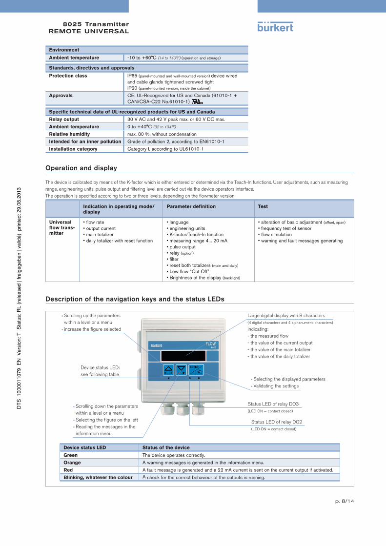
Description of the navigation keys and the status LEDs
Scrolling up the parameters
within a level or a menu
increase the figure selected
Device status LED:
see following table Selecting the displayed parameters
Validating the settings
Status LED of relay DO3
(LED ON = contact closed)
Large digital display with 8 characters
(4 digital characters and 4 alphanumeric characters)
indicating:
- the measured flow
- the value of the current output
- the value of the main totalizer
- the value of the daily totalizer
Scrolling down the parameters
within a level or a menu
Selecting the figure on the left
Reading the messages in the
information menu
Status LED of relay DO2
(LED ON = contact closed)
Device status LED Status of the device
Green The device operates correctly.
Orange A warning messages is generated in the information menu.
Red A fault message is generated and a 22 mA current is sent on the current output if activated.
Blinking, whatever the colour A check for the correct behaviour of the outputs is running.
8025 TransmitterREMOTE UNIVERSAL
p. 9/14
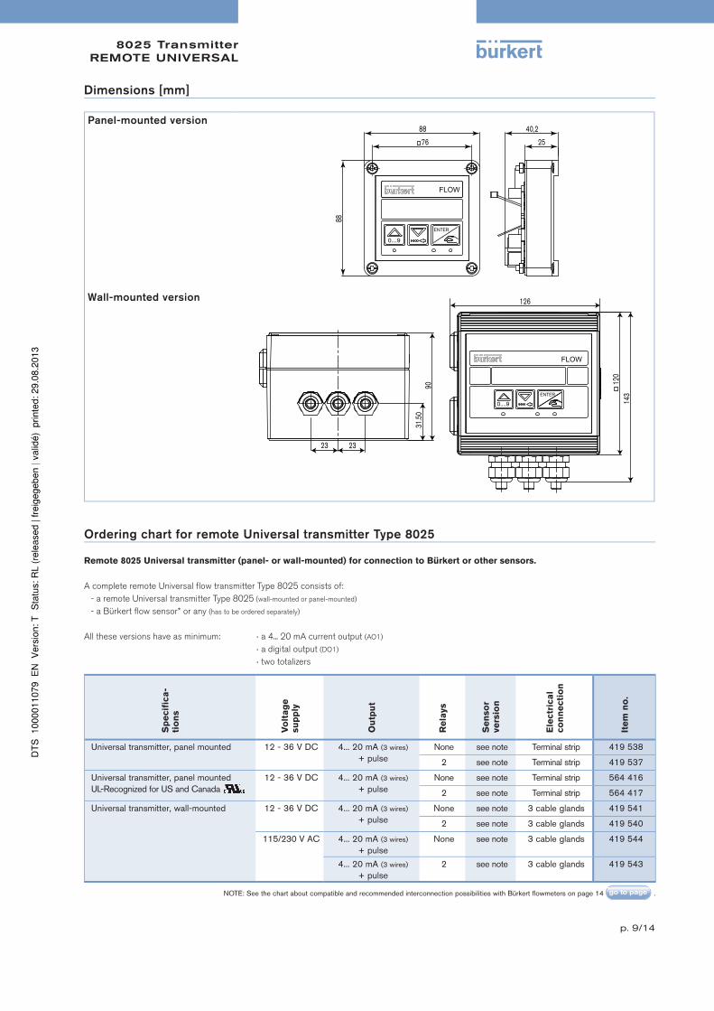
Dimensions [mm]
Panel-mounted version
88
88
76
ENTER
0....9
FLOW
25
40,2
Wall-mounted version
143
120
126
31.5
0 90
23 23
ENTER
0....9
FLOW
Ordering chart for remote Universal transmitter Type 8025
Remote 8025 Universal transmitter (panel- or wall-mounted) for connection to Bürkert or other sensors.
A complete remote Universal flow transmitter Type 8025 consists of:
- a remote Universal transmitter Type 8025 (wall-mounted or panel-mounted)
- a Bürkert flow sensor* or any (has to be ordered separately)
All these versions have as minimum: a 4... 20 mA current output (AO1)
a digital output (DO1)
two totalizers
Sp
ecif
ica
-
tio
ns
Vo
lta
ge
su
pp
ly
Ou
tpu
t
Re
lays
Se
nso
r
ve
rsio
n
Ele
ctr
ica
l
co
nn
ecti
on
Ite
m n
o.
Universal transmitter, panel mounted 12 - 36 V DC 4... 20 mA (3 wires)
+ pulseNone see note Terminal strip 419 538
2 see note Terminal strip 419 537
Universal transmitter, panel mountedUL-Recognized for US and Canada
12 - 36 V DC 4... 20 mA (3 wires)
+ pulseNone see note Terminal strip 564 416
2 see note Terminal strip 564 417
Universal transmitter, wall-mounted 12 - 36 V DC 4... 20 mA (3 wires)
+ pulseNone see note 3 cable glands 419 541
2 see note 3 cable glands 419 540
115/230 V AC 4... 20 mA (3 wires)
+ pulseNone see note 3 cable glands 419 544
4... 20 mA (3 wires)
+ pulse2 see note 3 cable glands 419 543
NOTE: See the chart about compatible and recommended interconnection possibilities with Bürkert flowmeters on page 14 .
8025 TransmitterREMOTE UNIVERSAL
p. 10/14
Ordering chart - accessories for remote Universal transmitter Type 8025 (has to be ordered separately)
Sp
ecif
ica
-
tio
ns
Ite
m n
o.
Spare part, panel version
Mounting set (screws, washer, nuts, cable clips) 554 807
Seal 419 350
Set with 8 FLOW foils 553 191
Spare part, wall version
Power supply board 115/230 V AC + mounting instruction sheet 555 722
8025 TransmitterREMOTE
p. 11/14
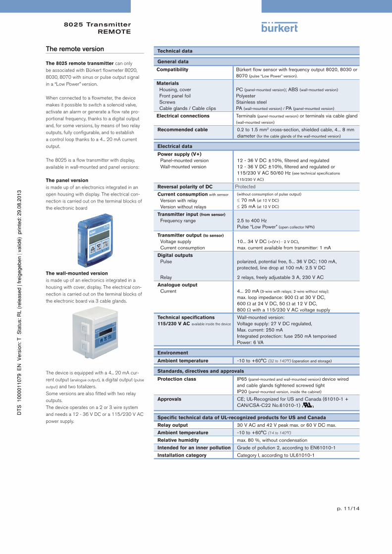
The remote version
The 8025 remote transmitter can only
be associated with Bürkert flowmeter 8020,
8030, 8070 with sinus or pulse output signal
in a “Low Power” version.
When connected to a flowmeter, the device
makes it possible to switch a solenoid valve,
activate an alarm or generate a flow rate pro-
portional frequency, thanks to a digital output
and, for some versions, by means of two relay
outputs, fully configurable, and to establish
a control loop thanks to a 4... 20 mA current
output.
The 8025 is a flow transmitter with display,
available in wall-mounted and panel versions:
The panel version
is made up of an electronics integrated in an
open housing with display. The electrical con-
nection is carried out on the terminal blocks of
the electronic board
The wall-mounted version
is made up of an electronics integrated in a
housing with cover, display. The electrical con-
nection is carried out on the terminal blocks of
the electronic board via 3 cable glands.
The device is equipped with a 4... 20 mA cur-
rent output (analogue output), a digital output (pulse
output) and two totalizers.
Some versions are also fitted with two relay
outputs.
The device operates on a 2 or 3 wire system
and needs a 12 - 36 V DC or a 115/230 V AC
power supply.
Technical data
General data
Compatibility Bürkert flow sensor with frequency output 8020, 8030 or 8070 (pulse “Low Power” version).
Materials
Housing, coverFront panel foilScrewsCable glands / Cable clips
PC (panel-mounted version); ABS (wall-mounted version)
PolyesterStainless steelPA (wall-mounted version) / PA (panel-mounted version)
Electrical connections Terminals (panel-mounted version) or terminals via cable gland (wall-mounted version)
Recommended cable 0.2 to 1.5 mm2 cross-section, shielded cable, 4... 8 mm diameter (for the cable glands of the wall-mounted version)
Electrical data
Power supply (V+)
Panel-mounted versionWall-mounted version
12 - 36 V DC ±10%, filtered and regulated12 - 36 V DC ±10%, filtered and regulated or115/230 V AC 50/60 Hz (see technical specifications
115/230 V AC)
Reversal polarity of DC Protected
Current consumption with sensor
Version with relayVersion without relays
(without consumption of pulse output)
70 mA (at 12 V DC)
25 mA (at 12 V DC)
Transmitter input (from sensor)
Frequency range 2.5 to 400 HzPulse “Low Power” (open collector NPN)
Transmitter output (to sensor)
Voltage supplyCurrent consumption
10... 34 V DC (=(V+) - 2 V DC),max. current available from transmitter: 1 mA
Digital outputs
Pulse
Relay
polarized, potential free, 5... 36 V DC; 100 mA,protected, line drop at 100 mA: 2.5 V DC
2 relays, freely adjustable 3 A, 230 V AC
Analogue output
Current 4... 20 mA (3-wire with relays; 2-wire without relay);
max. loop impedance: 900 at 30 V DC,600 at 24 V DC, 50 at 12 V DC,800 with a 115/230 V AC voltage supply
Technical specifications
115/230 V AC available inside the device
Wall-mounted version:Voltage supply: 27 V DC regulated,Max. current: 250 mAIntegrated protection: fuse 250 mA temporisedPower: 6 VA
Environment
Ambient temperature -10 to +60°C (32 to 140°F) (operation and storage)
Standards, directives and approvals
Protection class IP65 (panel-mounted and wall-mounted version) device wired and cable glands tightened screwed tightIP20 (panel-mounted version, inside the cabinet)
Approvals CE; UL-Recognized for US and Canada (61010-1 + CAN/CSA-C22 No.61010-1)
Specific technical data of UL-recognized products for US and Canada
Relay output 30 V AC and 42 V peak max. or 60 V DC max.
Ambient temperature -10 to +60°C (14 to 140°F)
Relative humidity max. 80 %, without condensation
Intended for an inner pollution Grade of pollution 2, according to EN61010-1
Installation category Category I, according to UL61010-1
8025 TransmitterREMOTE
p. 12/14
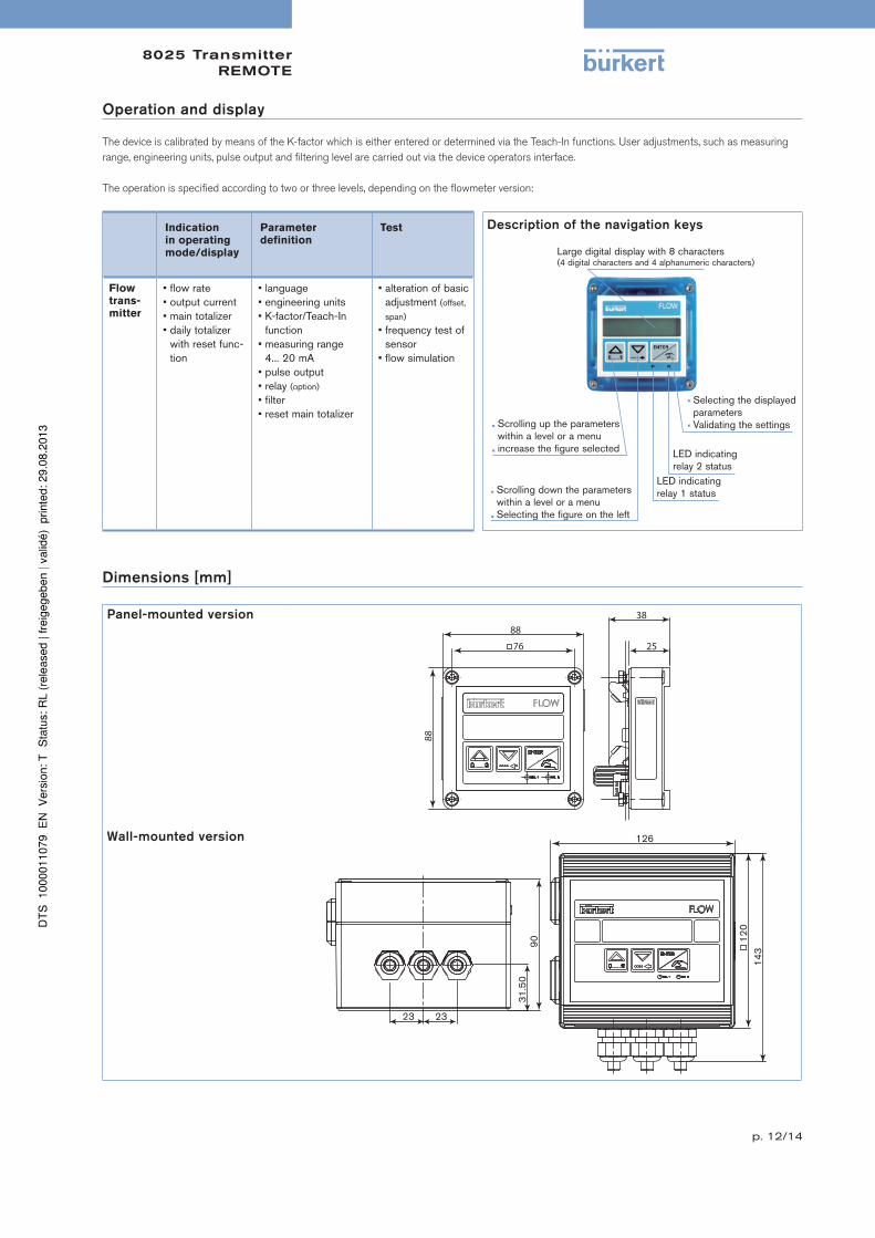
Operation and display
The device is calibrated by means of the K-factor which is either entered or determined via the Teach-In functions. User adjustments, such as measuring
range, engineering units, pulse output and filtering level are carried out via the device operators interface.
The operation is specified according to two or three levels, depending on the flowmeter version:
Indication
in operating
mode/display
Parameter
definition
Test Description of the navigation keys
Selecting the displayed parameters
Validating the settings
Large digital display with 8 characters(4 digital characters and 4 alphanumeric characters)
Scrolling down the parameters within a level or a menu
Selecting the figure on the left
Scrolling up the parameters within a level or a menu
increase the figure selected LED indicating relay 2 status
LED indicating relay 1 status
Flow
trans-
mitter
• flow rate• output current• main totalizer• daily totalizer
with reset func-tion
• language• engineering units• K-factor/Teach-In
function• measuring range
4... 20 mA• pulse output• relay (option)
• filter • reset main totalizer
• alteration of basic adjustment (offset,
span)
• frequency test of sensor
• flow simulation
Dimensions [mm]
Panel-mounted version
88
88
76 25
38
Wall-mounted version
8025 TransmitterREMOTE
p. 13/14
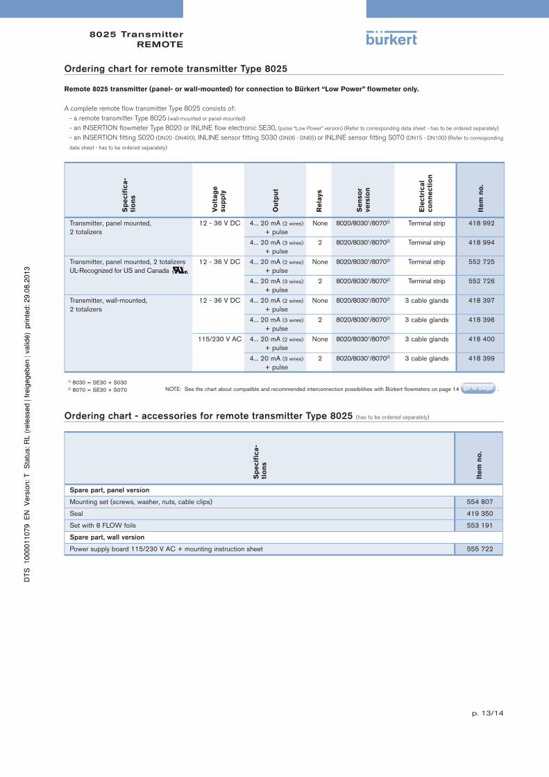
Ordering chart for remote transmitter Type 8025
Remote 8025 transmitter (panel- or wall-mounted) for connection to Bürkert “Low Power” flowmeter only.
A complete remote flow transmitter Type 8025 consists of:
- a remote transmitter Type 8025 (wall-mounted or panel-mounted)
- an INSERTION flowmeter Type 8020 or INLINE flow electronic SE30, (pulse “Low Power” version) (Refer to corresponding data sheet - has to be ordered separately)
- an INSERTION fitting S020 (DN20 -DN400), INLINE sensor fitting S030 (DN06 - DN65) or INLINE sensor fitting S070 (DN15 - DN100) (Refer to corresponding
data sheet - has to be ordered separately)
Sp
ecif
ica
-
tio
ns
Vo
lta
ge
su
pp
ly
Ou
tpu
t
Re
lays
Se
nso
r
ve
rsio
n
Ele
ctr
ica
l
co
nn
ecti
on
Ite
m n
o.
Transmitter, panel mounted,2 totalizers
12 - 36 V DC 4... 20 mA (2 wires) + pulse
None 8020/80301/80702) Terminal strip 418 992
4... 20 mA (3 wires)
+ pulse2 8020/80301/80702) Terminal strip 418 994
Transmitter, panel mounted, 2 totalizersUL-Recognized for US and Canada
12 - 36 V DC 4... 20 mA (2 wires)
+ pulseNone 8020/80301/80702) Terminal strip 552 725
4... 20 mA (3 wires)
+ pulse2 8020/80301/80702) Terminal strip 552 726
Transmitter, wall-mounted,2 totalizers
12 - 36 V DC 4... 20 mA (2 wires)
+ pulseNone 8020/80301/80702) 3 cable glands 418 397
4... 20 mA (3 wires)
+ pulse2 8020/80301/80702) 3 cable glands 418 396
115/230 V AC 4... 20 mA (2 wires)
+ pulseNone 8020/80301/80702) 3 cable glands 418 400
4... 20 mA (3 wires)
+ pulse2 8020/80301/80702) 3 cable glands 418 399
1) 8030 = SE30 + S0302) 8070 = SE30 + S070 NOTE: See the chart about compatible and recommended interconnection possibilities with Bürkert flowmeters on page 14 .
Ordering chart - accessories for remote transmitter Type 8025 (has to be ordered separately)
Sp
ecif
ica
-
tio
ns
Ite
m n
o.
Spare part, panel version
Mounting set (screws, washer, nuts, cable clips) 554 807
Seal 419 350
Set with 8 FLOW foils 553 191
Spare part, wall version
Power supply board 115/230 V AC + mounting instruction sheet 555 722
8025 FlowmeterINSERTION
p. 14/14
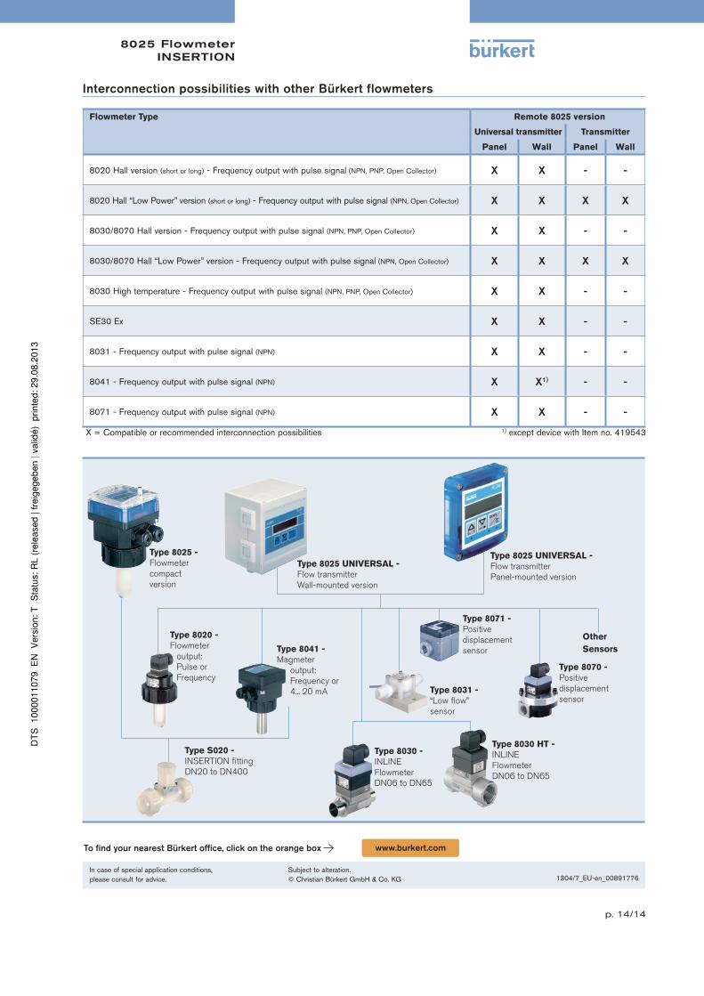
Interconnection possibilities with other Bürkert flowmeters
Flowmeter Type Remote 8025 version
Universal transmitter Transmitter
Panel Wall Panel Wall
8020 Hall version (short or long) - Frequency output with pulse signal (NPN, PNP, Open Collector) X X - -
8020 Hall “Low Power” version (short or long) - Frequency output with pulse signal (NPN, Open Collector) X X X X
8030/8070 Hall version - Frequency output with pulse signal (NPN, PNP, Open Collector) X X - -
8030/8070 Hall “Low Power” version - Frequency output with pulse signal (NPN, Open Collector) X X X X
8030 High temperature - Frequency output with pulse signal (NPN, PNP, Open Collector) X X - -
SE30 Ex X X - -
8031 - Frequency output with pulse signal (NPN) X X - -
8041 - Frequency output with pulse signal (NPN) X X1) - -
8071 - Frequency output with pulse signal (NPN) X X - -
X = Compatible or recommended interconnection possibilities 1) except device with Item no. 419543
Type 8025 UNIVERSAL -
Flow transmitter
Wall-mounted version
Type 8020 -
Flowmeter
output:
Pulse or
Frequency
Type 8041 -
Magmeter
output:
Frequency or
4... 20 mA
Type S020 -
INSERTION fitting
DN20 to DN400
Type 8025 UNIVERSAL -
Flow transmitter
Panel-mounted version
Other
Sensors
Type 8071 -
Positive
displacement
sensor
Type 8031 -
“Low flow”
sensor
Type 8030 -
INLINE
Flowmeter
DN06 to DN65
Type 8030 HT -
INLINE
Flowmeter
DN06 to DN65
Type 8025 -
Flowmeter
compact
version
Type 8070 -
Positive
displacement
sensor
To find your nearest Bürkert office, click on the orange box www.burkert.com
In case of special application conditions,please consult for advice.
Subject to alteration.© Christian Bürkert GmbH & Co. KG 1304/7_EU-en_00891776


![OVAL VORTEX FLOWMETER / THERMISTOR TYPE VORTEX … · 2019. 1. 10. · 3 OVAL VORTEX FLOWMETER GBD110E-6 FLOW RANGES The OVAL VORTEX FLOWMETER measures actual flow rate (m3/h[actual])](https://img.pdfslide.us/doc/110x75/5fec29af0bfeaf2fc470a314/oval-vortex-flowmeter-thermistor-type-vortex-2019-1-10-3-oval-vortex-flowmeter.jpg)