Embed Size (px)
Citation preview

Research Collection
Report
A finite element framework for geotechnical applications basedon object-oriented programming
Author(s): Fritz, Pit; Zheng, Xiong
Publication Date: 2002
Permanent Link: https://doi.org/10.3929/ethz-a-004230928
Rights / License: In Copyright - Non-Commercial Use Permitted
This page was generated automatically upon download from the ETH Zurich Research Collection. For moreinformation please consult the Terms of use.
ETH Library

Division of Geotechnical EngineeringDepartment of Rock Engineering and Tunnelling
Swiss Federal Institute of Technology – Zürich
A Finite Element Framework forGeotechnical Applications based onObject-Oriented Programming
byPit (Peter) FRITZDivision of Geotechnical EngineeringSwiss Federal Institute of Technology, Zürich, Switzerland
andXiong ZHENGformerly at Division of Geotechnical Engineeringnow at Union Bank of Switzerland UBSZürich, Switzerland
January, 2002

IMAGINE – an FE FrameworkPage II
Address of the Authors:Pit (Peter) FRITZ, Dr. sc. techn.Xiong ZHENG, Dr.Division of Geotechnical EngineeringSwiss Federal Institute of TechnologyCH – 8093 ZürichSwitzerland
e-mail: [email protected]: http://pit.fritz.net

Content Page III
Content
ABSTRACT................................................................................................................................................................. V
1 INTRODUCTION................................................................................................................................................... 1
2 MOTIVATION........................................................................................................................................................ 3
2.1 INTRODUCTION................................................................................................................................................... 32.2 PROCEDURAL PROGRAMMING PARADIGM........................................................................................................... 32.3 OTHER PROGRAMMING PARADIGMS.................................................................................................................... 42.4 OBJECT-ORIENTED PROGRAMMING PARADIGM ................................................................................................... 52.5 REQUIREMENTS FOR LARGE PROGRAMMING SYSTEMS, OR HOW OBJECT-ORIENTED PROGRAMMING MEETS THE
GOALS................................................................................................................................................................. 62.6 SUMMARY .......................................................................................................................................................... 8
3 OBJECT-ORIENTED ANALYSIS: AIM AND FUNCTIONALITY OF THE FE FRAMEWORKIMAGINE ................................................................................................................................................................ 9
3.1 INTRODUCTION................................................................................................................................................... 93.2 AIM OF THE FRAMEWORK ................................................................................................................................... 93.3 DOCUMENTATION............................................................................................................................................. 103.4 OBJECT DATABASE ........................................................................................................................................... 10
3.4.1 Introduction ........................................................................................................................................... 103.4.2 Persistence............................................................................................................................................. 113.4.3 Object-oriented database ...................................................................................................................... 14
3.5 DEVELOPMENT ENVIRONMENT ......................................................................................................................... 163.6 FE KERNEL....................................................................................................................................................... 173.7 GEOMETRIC MODELING .................................................................................................................................... 183.8 POSTPROCESSING ............................................................................................................................................. 203.9 PROJECT MANAGEMENT.................................................................................................................................... 203.10 USER INTERFACE .............................................................................................................................................. 213.11 STATE OF THE ART ........................................................................................................................................... 22
4 OBJECT-ORIENTED DESIGN AND IMPLEMENTATION OF THE FE FRAMEWORK IMAGINE ... 25
4.1 GUIDELINES...................................................................................................................................................... 254.2 ARCHITECTURE OF IMAGINE ......................................................................................................................... 264.3 PROJECT AND RESOURCE MANAGEMENT SUBSYSTEM ....................................................................................... 27
4.3.1 Project view and control........................................................................................................................ 274.3.2 Geometric modeling .............................................................................................................................. 294.3.3 Project resources and their management .............................................................................................. 324.3.4 Analysis and task control....................................................................................................................... 35
4.4 FE MODELING SUBSYSTEM ............................................................................................................................... 384.4.1 Overview................................................................................................................................................ 384.4.2 Modeling classes and field variable classes .......................................................................................... 39
4.4.2.1 Overview.....................................................................................................................................................394.4.2.2 Element concept..........................................................................................................................................424.4.2.3 Node and degrees of freedom (DOF) concept.............................................................................................454.4.2.4 Load concept ...............................................................................................................................................464.4.2.5 Constraint concept.......................................................................................................................................474.4.2.6 Material concept..........................................................................................................................................48
4.4.3 Numerical classes .................................................................................................................................. 494.4.4 Global representations .......................................................................................................................... 514.4.5 Basic classes .......................................................................................................................................... 53

IMAGINE – an FE FrameworkPage IV
5 DESIGN AND IMPLEMENTATION OF THE USER INTERFACE .............................................................55
5.1 INTRODUCTION .................................................................................................................................................555.2 WORKBENCH APPROACH...................................................................................................................................55
5.2.1 Overview ................................................................................................................................................555.2.2 Kinds of workbenches ............................................................................................................................575.2.3 Layout of a workbench...........................................................................................................................58
5.3 FEM MODELING WORKBENCH ..........................................................................................................................595.3.1 Geometric resources at the project level................................................................................................595.3.2 Modeling resources at the project level .................................................................................................62
5.3.2.1 Design of the interface ................................................................................................................................625.3.2.2 Resource forms ...........................................................................................................................................64
5.3.3 Meshing..................................................................................................................................................685.3.4 Conclusions............................................................................................................................................72
5.4 FEM TASK WORKBENCH ...................................................................................................................................725.4.1 Overview ................................................................................................................................................725.4.2 Task manager.........................................................................................................................................725.4.3 Task objects............................................................................................................................................755.4.4 Command objects...................................................................................................................................775.4.5 Conclusions............................................................................................................................................80
6 EXAMPLE .............................................................................................................................................................81
6.1 INTRODUCTION .................................................................................................................................................816.2 SECTOR WITHOUT LINING..................................................................................................................................816.3 SOLID MODEL VERSUS SUPERELEMENTS............................................................................................................89
7 CONCLUSIONS ....................................................................................................................................................93
APPENDIX 1: FROM PROCEDURAL TO OBJECT-ORIENTED PROGRAMMING ...................................95
APPENDIX 2: SOFTWARE LIFE CYCLE ............................................................................................................97
APPENDIX 3: THE DOCUMENT-VIEW CONCEPT OF THE MFC ................................................................99
APPENDIX 4: STYLE GUIDE...............................................................................................................................101
INTRODUCTION .......................................................................................................................................................101ONLINE DOCUMENTATION ......................................................................................................................................101NAMING CONVENTIONS ..........................................................................................................................................102
REFERENCES .........................................................................................................................................................105

Abstract Page V
Abstract
This publication describes an alternative methodology for finite element programming based onobject-oriented techniques. The concepts of object-oriented programming are outlined and it isexplained, how this new paradigm facilitates design, implementation and support of largeprogramming systems. Because the knowledge of object-oriented programs is not dispersed in theactual code, but rather localized in structures, the causal knowledge, meta knowledge andconstraints may be integrated in a uniform manner. Control structures separate the external level('what') from the internal ('how') by encapsulating the actual implementation. As programminglanguage C++ is used.
Up till now several object-oriented finite element frameworks have been presented which arepartially extendable. However, the extendibility is limited to a few specific directions, e.g. theintroduction of new element types or solving strategies. Much less support is available for taskcontrol, creation of new material models, configurable field variable types or extensions of theanalysis model. No framework is available which is especially designed to cover the problemsencountered when dealing with geotechnical engineering. IMAGINE tries to close these gaps.
The nucleus of the Finite Element framework presented relies on abstractions, which includecommon concepts accepted in mathematics, mechanics, engineering and interactive visualizationtechniques, and serve as the fundamental object-oriented framework of classes for finite elementapplications and task management. The aim of the framework was not to include as manyfeatures as possible (e.g. a variety of types of finite elements or material laws), but to provide asophisticated and robust foundation which may be used in the future due to its inherentcapabilities of simple maintenance, adaptability to new resources and extendibility, especiallydirected towards applications in geotechnical engineering.
Based on this framework an experimental finite element application for geomechanics ispresented. Here everything is regarded as an object: loads, load groups, computational tasks etc.Thanks to the graphical user interface under MS-Windows and the rule of non-anticipation onwhich the objects rely, the handling of the program is straightforward.Some test examples illustrate its usage.
Keywords: object-oriented programming, OOP, finite elements, framework, toolkit, C++,geotechnical engineering.

IMAGINE – an FE FrameworkPage VI

Introduction Page 1
1 IntroductionAs long as there were no machines, programming was no problem at all; when we had afew weak computers, programming became a mild problem, and now we have giganticcomputers, programming has become an equally gigantic problem (Dijkstra, 1972).
Typically, development of finite element codes has been started by research organizations. Thenthe codes have been transferred to private companies, where they have been extended andenhanced. The researchers have been left with a multitude of rather incomplete code fragments,each tailored to a specific topic of interest. Due to advances in programming and because of theconventional, inflexible design, scientists usually could not rely on existing code and had to startpractically from scratch for each new research project which extended the current model.Furthermore, for scientific consulting work or for teaching purposes, they used some third partysoftware which was, at least for geotechnical engineering, not one hundred per cent tailored tothe specific problem to be solved, but was much easier to handle thanks to an elaborate,comfortable user interface.Therefore, research organizations would benefit from a Finite Element framework1 forgeotechnical applications which should provide (in an easy way) extendibility, reusability, understandability from the programmer's point of view, maintainability, a basic set of the most often used features, and a satisfactory user interface which may be complemented by third party software.
Numerical analyses just provide a limited contribution to the design process in geotechnicalengineering. Equally important aspects are geology, measurements in situ and in the laboratory,and mainly experience. On the other hand the fundamentals of modeling in numerics are quitedemanding. Even the most important material, the rock or soil, cannot be chosen, but is justencountered. It is not unusual that the introduction of just one new model parameter, e.g. swellingbehavior, may lead to a multitude of research works. For these reasons private industry iscommercially not willing (or able) to develop Finite Element (FE) programs for solving specialproblems in geotechnical engineering or research work. However, they agree that they do neednovel numerical tools. This is illustrated by a survey of the ASCE-sponsored UndergroundTechnology Research Council (UTRC, 1991) at 50 practitioners of underground engineeringcompanies. The highest priority for research work was assigned to the problem of groundwaterinflow into tunnels, which requires investigations with both numerical models and fieldobservation.Therefore, special-purpose FE codes have to be developed by research groups.
1 A framework is a collection of classes that provide a set of services for a particular domain (Booch, 1994), e.g. forbuilding compilers.

IMAGINE – an FE FrameworkPage 2
Additionally, for research organizations in geotechnical engineering it is absolutely necessary toget some feedback from industry, if they should not loose the practical basis in their researchprojects. Therefore, they are strongly interested in keeping up the exchange of experience withpracticing engineers, which is guaranteed if industry uses their programs.

Motivation Page 3
2 Motivation
2.1 IntroductionSince many years, professionals have been aware of the so-called software crisis (Wirfs et al.,1990). The main problem of large software systems is the great effort necessary for thecontinuous support of software, i.e. maintenance, e.g. debugging, adaptation to new resources (e.g. compilers or hardware), and extensions.
This is particularly true for FE programs. An increasing demand on new analytic capabilities,constitutive models and easy-to-handle graphical user interfaces requires the introduction of newdesign methodologies. However, as a matter of fact, current textbooks on the Finite ElementMethod (FEM) are still very similar to those of two decades ago. This is also illustrated by 60%of all codes of engineering software being written in FORTRAN, about 6% in C and 0% inobject-oriented C++ (Smith, 1994). Only a handful of research projects have been undertaken inthe last few years to overcome these limitations.The current section will highlight some of the reasons why conventional programming paradigmscoupled with programming languages introduced 40 years ago are not able to help solving thesoftware crisis, and which perspectives seem to be most promising to overcome this problem.
2.2 Procedural programming paradigmPractically all current FE codes of significance rely on the FORTRAN programming language, anexponent of the procedural programming paradigm. Therefore, the current subsection is limitedto the discussion of FORTRAN. Furthermore, it is assumed that the nomenclature as outlined in"Appendix 1: From procedural to object-oriented programming", is known.A procedural program may be viewed as a set of algorithms, controlled by an imperativelanguage (Miller, 1989). Disregarding technical aspects such as the limited syntax of e.g.FORTRAN, which partly have been overcome with the latest version (FORTRAN 90), the basicproblems of procedural programming stem from the following inherent conceptual shortcomings: just one level of functional abstraction1, no data abstraction, no localization of data, no information hiding, semantic breaks.
The design of the FORTRAN language does not envisage any abstraction or structuring, exceptthe decomposition in subroutines. However, subroutines provide just one and only one level ofprocess or functional decomposition (e.g. input, solve, reading data from an array etc.).Therefore, e.g. task management, user interaction, numerical algorithms and data representationare all handled at the same level. Furthermore, they are not handled directly as concepts, butconcentrate on low level implementation details (Baugh and Rehak, 1989). Procedural 1 Abstractions include two different aspects: an "abstraction" idealizes an entity by describing its most essentialproperties only, and it hides what capabilities the entity possesses from how they are reached.

IMAGINE – an FE FrameworkPage 4
programming relies on how to compute (retrieve geometry, material properties etc., and thencompute stiffness), instead of the more understandable declarative approach of what to compute(ask the element to compute its stiffness).
Due to the missing abstraction levels, information hiding is rarely used. Welcome exceptions maybe the concentration of low level plotting commands in a few routines or a difficult to implementmemory management (Fritz, 1983).
For data no corresponding decomposition or localization may be defined. Only simple datastructures are available, which must be put at the subroutines disposal either as globallyaccessible (and changeable) COMMON-blocks, or as long and involved parameter lists, whichare prone to errors and side effects. It is rumored that such a side effect cost a company US$ 1.6billions due to one single incorrect character (Berard, 1993, p.41).
Information hiding with regard to data is practically not achievable. Data are just representationsof values (e.g. coordinates), but not concepts e.g. of a node. They do not possess any additionalknowledge. Therefore, the program flow must be strictly sequential, guided by a rigid controlstrategy.
Semantic breaks occur in two circumstances:First, already in the stage of analysis, concepts are replaced by functional decomposition or/and adata-oriented composition (Groth et al., 1994). In the design phase the individual entities areassembled to collections of similar subject or behavior. During implementation the same entitymay include code ranging from a very high down to a very low complexity or abstraction level.And the test phase must follow the semantics of the three foregoing phases. Obviously, semanticbreaks occur all along the life cycle of a project.Second two different programming paradigms are often used: one for the engineering part of thesoftware and the other for the database management system (DBMS) (Yu and Adeli, 1993).Conventional DBMSs of large FE systems usually just rely on the flat relational data model.Semantic breaks lead to inhomogeneities in design and implementation, which impair readability,localization of tasks and recursive development.
2.3 Other programming paradigmsIn view of the limitations of the procedural programming paradigm research concentrated onfinding a new conceptual architecture which should lead to programs which are easy tounderstand and modify. Some of the perspectives at hand are: Database Management Systems: in view of the large, complex data structures of FE systems
this approach puts the DBMS in the center of interest (Felippa, 1985). However, engineeringparts must still be added, which leads to the above mentioned problem of global accessibilityof data and inhomogeneity.
General Programming Systems: this concept is based on collections of subroutines, whereeach set performs an independent computational task (Mo, 1978). This is less a newprogramming paradigm, than an improved programming technique.
Logic or Constraint-Oriented Programming: a program consists of a set of rules which areprocessed by an inference engine (Buchanan, 1983). Logic programming is often used whenmetaknowledge is involved (rules of thumb), but less for mathematically precise applications

Motivation Page 5
like the nucleus of an FE program. However, even for FEM many problems remain which maybe solved with logic programming, e.g. abstraction of the real world, or task control.
Functional Programming: a program is viewed as a flow of data through recursive functioncalls. This concept should not be confused with dataflow hardware, even when this type ofhardware seems more suitable to host this technique compared to a purely sequential VonNeumann machine (Dwyer, 1989). Although taking into account that even FE programs havebeen written with purely functional languages like Lisp (Baugh and Rehak, 1989) or SASL(Dwyer, 1989), it seems more research is needed to prove their applicability with respect toefficiency and algorithm design.
Generic Programming relies on classifying abstract software components and their behaviorwhich results in a standard taxonomy (Stevens, 1995). The emphasis is on the semantics andsemantic classification, while object-oriented languages place stronger emphasis on how tobuild class hierarchies, and not what should be inside. Main application domains for genericprogramming are expected in list management, search algorithms, databases etc., but less inspecific mathematical applications as the FEM. An outflow of generic programming, the so-called Standard Template Library (STL) has recently been approved by the ANSI/ISO-committee as part of standard C++, therefore the future will enable inclusion automatically.
2.4 Object-oriented programming paradigmThe remaining and most promising approach to discuss is the object-oriented programmingparadigm. This paradigm is more the result of an evolutionary process, than of a revolution (c.f."Appendix 1: From procedural to object-oriented programming"). Here it is assumed that theunderlying theory is known (c.f. Lippman, 1998). Just a few characteristics will be outlined,which either seem very important to us in the actual context, or which up till now have not founda unique definition. As the FE framework IMAGINE is written in the programming languageC++, the way of understanding terms will adopt to that of the C++ community.
Object-oriented programming (OOP) shall be defined as a paradigm relying on data abstraction, i.e. abstract data types or classes, inheritance, and polymorphism, i.e. dynamic binding.
The authors of this report do not request data type completeness as a prerequisite for OOP, assome authors of pure object-oriented languages do.
A class is a template of a self-contained computational entity and defines usually the analog of areal world item, but may also define an abstract concept (e.g. an operation). It possesses attributes(so-called member data or instance variables) and may respond to or may be subjected to actions.Encapsulation enables to hide information inside a class. Thanks to different levels ofabstractions information hiding may vary in degree (to the outside of a class or even inside a classhierarchy).
Instances of classes are called objects. Also instances of parameterized classes are called objects,i.e. they are not treated as so-called metaclasses as in other languages. Objects communicate witheach other by sending messages, i.e. executing their member functions or so-called methods.

IMAGINE – an FE FrameworkPage 6
Inheritance allows the creation of hierarchically structured class systems, with different levels ofconcern or abstraction. Four classes of inheritance relationships may be distinguished: Specialization: from a base class a specialized subclass is derived, which redefines some
properties of the base class. The base class captures the similarities between objects, thesubclass the differences. The base class is said to be a generalization of its subclass. Inheri-tance allows one to exploit the commonality between classes without introducing redundancy.
Extension: similar to specialization, but some properties are added to the derived class. Modification: similar to specialization, but some properties of the base class are not inherited.
They are hidden or masked out in the derived class. Aggregation: complex objects may be constructed by embedding other objects in a class.
Polymorphism includes both compile-time and run-time polymorphism. The former is also calledearly binding, the latter late binding (c.f. "Appendix 1: From procedural to object-orientedprogramming"). Polymorphism enables a higher level of abstraction in software design, therebyenhancing understandability and maintainability.
2.5 Requirements for large programming systems, or how object-orientedprogramming meets the goals
Under large programming systems codes with tens of thousands of lines are understood, asopposed to small programs with several thousands of lines, or very large systems, with manyhundreds of thousands or millions of lines. The latter may present completely different problems(e.g. communication between development groups), which are not covered here.The most important requirements for a large FE system are the following: simple software support, i.e. easy maintenance, adaptation to new resources and extendibility, reusability, implying understandability (readability, traceability, learnability), homogeneity
and portability, reliability, which designates the probability with which software does not cause the failure of a
system, or lead to incorrect results, software security, which means the degree to which software protects itself from unauthorized
actions, software safety, i.e. the probability that even an unintended usage does not lead to a mishap
(hazard).

Motivation Page 7
These requirements are met by OOP in the following way: Localization of data facilitates maintenance through the absence (to a large extent) of side
effects. However, emphasis must be placed on minimal object coupling to reach this goal.Inheritance and parameterized types improve adaptability and extendibility, in that they doaway with copying of source code as is usual in conventional approaches. The declarativeapproach of OOP seems to be nearer to human nature than the procedural one.Uncoupling of flow control from engineering algorithms facilitates future combination withtechniques of artificial intelligence.
Reusability is perhaps the most promising feature of OOP. This implies not only reusabilityper se, i.e. for other projects, but also with regard to major extensions of the current project.The Alpha and Omega of reusability is understandability. Readability in the small may beachieved by standardized class headers, listing usage, external relation and position in theclass hierarchy. Readability in the large, traceability and portability are achieved by severallevels in the abstraction hierarchy, each of which treating homogeneous objects of interest.Learnability of OOP systems is supported by class hierarchies which group topics, andpolymorphism which reduces the number of function names to remember. Abstract data typeslet the programmer work at higher levels of abstraction.Thanks to the iterative or even recursive design process common in OOP (Berard, 1993), it isusual to condense out abstract base classes and possible frameworks all along the life cycle ofa project, thereby creating new class hierarchies which lead to a cleaner and better design.Larger object-oriented applications will end up consisting of layers of frameworks thatcooperate with each other (Gamma et al., 2000).
Software reliability, security and safety are supported by transferring responsibility from theprogrammers to the program: e.g. constructors guarantee, if correctly applied, that noundefined variables exist, and destructors, that the resources are freed whenever they are notneeded anymore.
However, there are also some drawbacks of OOP. An important one is, that the demands on thedevelopers are substantially higher. In the field of engineering developers are often notprofessional software engineers, so they feel discouraged by the complexity of OOP and the steeplearning curve. Learning an OOP language means not only learning a new language, but gettingacquainted with a new way of thinking. This may be the reason that most FE programs have beenand are still being written in FORTRAN, thereby wasting resources as outlined above.At this point it should also be noted, that the power of OOP is not only based on the tools andtechniques provided by the underlying programming language, but also on the attitude of thedevelopers. It is said from Smalltalk programmers, that they need more time to browse throughexisting classes, than to code their own ones. An attitude which is certainly a proof forreusability, and which is not common for conventional programmers. The OOP paradigm allowsthe introduction of abstractions, but they are only exploited to their full potential by programmerswith an obsession for simplicity and perfection (Johnson and Foote, 1988). Unfortunately it isalso possible to program with an OOP language in a style similar to FORTRAN or C.
When choosing OOP there still remains the choice of the programming language. This is partly amatter of taste and will therefore not be discussed here to its full extent. Suffice to say that theprogramming language C++ was chosen primarily because of its widespread usage, whichguarantees its continuity in the future. Additionally, the following technical aspects support thisdecision:

IMAGINE – an FE FrameworkPage 8
efficiency: several comparisons report similar efficient code for C++ as for FORTRAN,which, up till now, was considered to lead to the most efficient code for scientific applications(apart from the Assembler language). This is illustrated by Fig. 1, where the deviations of theCPU-times of C and C++ with respect to FORTRAN are displayed. The differences are quitesmall. The influence of the hardware platform being used on this relationship may be biggerthan the inherent difference between C, C++ and FORTRAN itself.
modern operating systems themselves are usually largely written in C or its superset C++.Therefore, using C++ allows one to take advantage directly of the existing highly optimizedoperating system library.
for the chosen development environment Microsoft (MS)-Windows a powerful framework inC++ exists, the MS-foundation class library (MFC), which provides an architecture forabstracting the user interface and other essential components of a Windows application. Usingthis framework enlightens programming considerably.
Fig. 1 CPU times of a matrix by vector product for C, C++ and FORTRAN (normalized toFORTRAN) after Bruaset et al. (1996).Computation: 1'000 multiplications of a sparse matrix of 1'000 rows with a vectorPlatforms: IBM RS6000/50, Silicon Graphics Indigo, HP 9000/735 and Sun
SPARCstation 10/512
2.6 SummaryFE programs in the field of Geotechnics involve a large number of topics, including modeling,mechanics, mathematics and visualization. The software itself should satisfy extreme efficiencyrequirements. It should enable the casual user to define his or her model in an easy and foolproofway, and the programmer to extend an application program to include a specific feature with aminimum amount of work and even more important, with minimal side effects.
OOP offers new possibilities from both the conceptual and the technical point of view.

Object-oriented analysis Page 9
3 Object-oriented analysis:aim and functionality of the FE framework IMAGINE
3.1 IntroductionThe life cycle of software viewed in the light of the object-oriented paradigm comprises Object-oriented requirement analysis (OOA), Object-oriented design (OOD), Object-oriented programming (OOP), Testing, and Maintenance.
A definition of these individual steps may be found in "Appendix 2: Software life cycle". In thecurrent and the following sections they are treated more closely with respect to the FEframework.
In the analysis phase the external characteristics of the system which are visible to the user(programmer) and the key abstractions are defined. Additionally, sources of information areidentified which may help to solve the task in hand, and an overall description of the wholesystem is given.
3.2 Aim of the frameworkThe objectives of the FE framework IMAGINE (Integrated Modeling and Analysis in Geotech-nics by finite Elements) are twofold: provide scientists and practicing engineers in the field of geotechnical engineering with the
means to develop applications tailored to their requirements, development of an example application for geomechanics for a de facto proof of the
applicability of the framework. Furthermore, this application might be used by students,scientists and practicing engineers.
The first aim requires as mentioned above extendibility (with regard e.g. to statical or physical modeling, algorithms and task
management), understandability from the programmer's point of view, maintainability,
and the second aim a basic set of the most frequently used features, a satisfying user interface.
It must be realized in advance that it is not aimed to develop a universal framework which maybe used for all kinds of FE application. An example of a universal FE system is NASTRANwhich required hundreds of man-years for development, further hundreds for maintenance, andstill cannot satisfy the specific needs of each engineer.

IMAGINE – an FE FrameworkPage 10
3.3 DocumentationAs a red thread documentation spans all the life cycles of a project. It is a vital factor for theunderstandability of a program. This starts already at the analysis and design phase, where it hasbeen suggested to summarize the characteristics of each class on so-called class cards (Wirfs etal., 1990). These list besides the position of the class in the hierarchy also the functionality andthe necessary cooperation (relations to other classes) to achieve it. A similar card is created foreach subsystem1 specifying the functionality and to which class its achievement is delegated.During the life cycle these cards are refined and extended to textual specifications. A similarapproach is propagated by Booch (1994), which replaces the cards by clouds with various typesof outlines indicating various states and relations. Additionally, he introduces sets of diagrams forobjects, modules and processes.The variety of methods for describing software modeling is unified and standardized by theUnified Modeling Language (UML), c.f. Oestereich (1998). The UML is a language and notationfor the specification, construction, visualization and documentation of software systems. It usesseveral diagram types, the most important of which are diagrams for classes, states of classes,sequence and collaboration of objects, use cases and components.
For IMAGINE which, according to the definition above, falls into the category of a large (asopposed to "very large") system, these procedures did not prove to be adequate, perhaps becauseof its limited size. Therefore for producing the documentation we distiguish the following phases: Object-oriented analysis: documentation of the systems aim and the semantics of its
functionality. Object-oriented design: documentation of the vision and the details of the architecture and its
key abstractions. Object-oriented programming: it is an old experience that it is very difficult to motivate
programmers to comment their code in separate manuals. Additionally, such manuals are oftennot up to date and therefore of limited value. Therefore, online descriptions inserted in thecode itself are recommended. This is the place where the programmer works, and where hewill effectively add or change comments easily when changing the code. Together with a classbrowser these descriptions must be sufficient for a new programmer to understand the wholeprogramming system.
Testing and maintenance: a suite of test examples serves to check firstly the correctness of theinitial code and secondly the stability along the maintenance phase.
3.4 Object database3.4.1 IntroductionVarious data models may be used for storing and accessing the data of an FE system. Thewidespread relational model relies on relations with attributes which in essence are representedin two-dimensional cross-linked tables of fixed record length. Another frequently applied modelis the indexed sequential one which allows to access records of variable length through indexes.Both models are based on relatively rigid record structures and are value-oriented.In contrast Smith and Smith (1977) postulated already before the emergence of OOP a modelanticipating exactly the idea of the OOP paradigm. They postulated a database design based onthe two abstraction mechanisms: 1 A subsystem is a conceptual entity which is defined (Wirfs et al., 1990) as an aggregation of classes and possiblyother subsystems which is responsible for a set of functionalities.

Object-oriented analysis Page 11
– generalization: individual objects are represented at a higher level of abstraction,– aggregation: individual objects are grouped together to higher level objects.
Models are then formed by sets of generalization hierarchies intersected with sets of aggregationhierarchies. Unfortunately at that time no programming language was available tailored explicitlyto this paradigm. The advantage of this design is that arbitrary entities may be modeled togetherwith their relations, which make it much easier to describe highly interrelated engineeringsystems. Furthermore, it smoothly fits into an object-oriented program avoiding semantic breaks.Because C++ does not include the ability to store and retrieve persistent objects as an inherentpart of the language, the problem of persistence will be treated first, independently of the problemof designing the classes which define persistent objects.
3.4.2 PersistenceThe basic idea of persistence with regard to objects is that an object should be able to write itscurrent state to persistent storage. However, introducing persistence in C++ is not an easy matterbecause of the variety of entities which may form an object. Such entities may be other objects,pointers or references to objects, pointers to virtual functions etc. In C++ objects are uniquelyidentified by their addresses. Because these addresses are changed after saving and restoringobjects and because C++ does not support the notion of an object identity, a system must add anidentity key to each object created to support persistence. This identity key is usually defined bythe objects class name and some unique number per class. Several approaches exist to cope withthese problems.
The simplest approach is avoiding all problems by using an object-oriented wrapper around anexisting relational database (c.f. VISTA++, 1991). However, this also reduces the benefits onewould gain with an object-oriented database.
Another approach is to extend C++ itself and write a preprocessor which translates it back tostandard C++ (c.f. POET, 1993). This preprocessor additionally creates a class dictionary whichenables e.g. following the connections of aggregated pointers to other persistent or not persistentobjects. Object identity is assigned automatically by the system. The advantage of this fullyautomatic approach is that, opposed to some other solutions presented below, besides somekeywords the programmer does not usually have to write additional code on how to save andrestore the objects. An exception is if a type contains variable length data which cannot bederived from the declaration. In this case the specifications of the type must be included in aspecial type manager. The disadvantage of the automatism is first its overhead, and second that itneeds a special preprocessor, which may lead to problems when using an integrated developmentenvironment.
The following approaches may be characterized by the idea, that the persistent classes mustparticipate in their own persistence.Perhaps the first implementation of persistence of objects in standard C++ is available in the NIHclass library of the National Institute of Health in Maryland, U.S.A. (Gorlen et al., 1990). Theprecondition is that persistent objects must be derived from a common base class Object1, whichmanages the identity of objects. The programmer is then responsible for adding to each of hisclasses (which should be made persistent) two virtual member functions with the actual code 1 In this report all class names and methods are written in bold characters.

IMAGINE – an FE FrameworkPage 12
firstly for calling the corresponding member function of its base class and secondly for readingand writing all member data. Pointers to user defined objects are originally not supported, butthey could easily be added.The NIH class library is a comprehensive framework of about 17 thousand lines of source codewhich extends the functionality of C++ similar to the one provided by Smalltalk-80 (Goldbergand Robson, 1983), i.e. persistence is just one of the features of the framework. Therefore, theoverhead just to take advantage of persistence would be far too big. Perhaps it would be possible,although quite costly, to extract and use just a subset responsible for persistence.
A similar approach, but limited to the problem of persistence, is offered by the PARODY classlibrary or database (Stevens, 1992). The precondition is that persistent objects must be derivedfrom a common base class named Persistent In contrast to the NIH library, reading and writingare initiated by the constructor and destructor in a sophisticated way (c.f. Fig. 2): e.g. thedestructor calls function SaveObject of class Persistent, which calls the user implementedfunction Write. There admissible data types (e.g. basic types) are saved individually withWriteObject, other types with SaveObject. To improve efficiency the list of admissible datatypes may be extended at will. In this way the types of data to be made persistent are not limitedand include pointers and references to other objects, pointers to virtual member functions etc.
Fig. 2 Object persistence flow (after Stevens, 1992)
The object's identity is defined by its class name and the embedded primary key to be specified inthe constructor. With this identity the built in database management system enables navigatingthe object database and e.g. retrieving individual objects in a specific sequence. When adding,changing or deleting objects via the database management system it automatically checks forviolation of class relationship integrity.PARODY seems to be the most powerful approach compared with its simplicity (it comprehendsabout 2 thousand lines of source code only). One drawback may be (which is true for all similarprocedures) that the classes must be derived from one common base object. If e.g. one would liketo use features of the Microsoft Foundation Classes, multiple inheritance would be necessarywhich firstly should be used judiciously (Meyers, 1998) and secondly may not be available (seebelow). However, the first statement may be mitigated because it refers mainly to the problemswhen using the so-called diamond layout of multiple inheritance, which does not apply for thiscase.
Object-oriented analysis Page 13
The Microsoft Foundation Classes Library MFC (Microsoft Visual C++, 1993) enable similarcapabilities with respect to persistence1. The precondition is that persistent objects must bederived from a common base class CObject, which, by the way does not support multipleinheritance. Analogous to the NIH class library, for each class a function Serialize must beoverridden which first calls its base class function Serialize and then actually reads/writes allmember variables. The MFC library uses an object of the CArchive class as a type safeintermediary between the object to be serialized and the storage medium. The object's identitiesare automatically managed by CArchive.MFC also supports the persistence of pointers but only for pointers pointing to objects derivedfrom CObject (i.e. every pointer in those objects must also point to CObject derivatives, and soon).The only methods available are basically ReadObject and WriteObject. No navigationalfeatures are available, i.e. objects must be retrieved in the same order in which they have beenstored. In practice the persistence feature of the MFC library may only be used forreading/writing the whole bunch of data at once. Typical interfaces of this are the Open and Savecommands in the File-menu.The MFC library provides additionally database classes designed to access any database forwhich an Open Database Connectivity (ODBC) driver is available. Such drivers exist typicallyfor a variety of record-oriented databases, e.g. relational databases. However, none are known tothe authors for object databases, and it is doubtful if they will ever be available due to thecompletely different organization of the database. Therefore, the database support (in contrast tothe persistence support!) of the MFC library is not used in the present work.
The FE framework IMAGINE just needs limited database features. E.g. object sorting andnavigation through the database are dispensable. The main emphasis lies on making datapersistent at the end of a session. During a session accessibility is important: storage, i.e. memorymanagement is delegated to the operating system.As development environment MS-Windows (see below) has been chosen, together with MS-Visual C++ and its MFC library for the user interface. Because the MFC library's base classCObject does not support multiple inheritance, usage of e.g. PARODY is excluded. Therefore,IMAGINE is based on the serialization support of the MFC library for implementing objectpersistence.From this example it may be seen how available resources, e.g. the compiler, may influencearchitectural decisions.
1 The MFC call persistence "serialization", probably because the data are written to a disk in a serial fashion.

IMAGINE – an FE FrameworkPage 14
3.4.3 Object-oriented databaseNo consensus exists on the definition of an object-oriented database. A narrow view could definethe database as the disk or memory file to where the persistent objects have been written. A moreusage-oriented view, which is used for this FE framework, defines the object database as the setof all persistent objects which may be written to and retrieved from secondary storage.Designing the classes which define persistent objects replaces the conventional database design.The advantage is that the actual program implementation and the database design all take place atthe same level of abstraction. In this way problems of integrity of the data (e.g. objects with thesame identity should not be stored twice, or objects which are still referenced should not bedeleted) and of consistency (e.g. redundant information should not be contradictory) are treatedin a natural way together with the normal class design.The object database should include three levels of abstraction: individual objects: instances of classes which should reside on the heap (and not the stack) to
avoid deletion when going out of scope, collections: a collection object is a set of individual object instances, database manager: in the case of the MFC library a CArchive object which allows storing and
retrieving of objects.
All individual objects which should be stored in the database must be made persistent as outlinedabove.Because in FE analyses large amounts of data may result, it is favorable to group them byincorporating them (actually just pointers to them) into collections.The bulk of persistent data of the framework may be grouped into two categories:1. collections of sequential objects where the main emphasis lies on easy and fast retrieval,2. collections of objects where the main emphasis lies on easy and fast insertion and deletion of
individual objects.
The MFC library provides three differently organized collections: lists: the list class provides an ordered, non-indexed list of elements (implemented as a doubly
linked list). A list may be accessed bi-directionally and inserts and deletes may be performedanywhere without undue performance penalties. However, searching a specific element isquite slow.
arrays: the array class provides a dynamically sized, ordered, and integer-indexed array ofobjects. Access is a matter of subscript operation and is therefore very fast. Insertion anddeletion of elements in the middle is slow because they involve shifting remaining entries.Also searching a specific element is slow.
maps (also known as dictionaries): a map is an unordered collection that associates a keyobject with a value object. It is one subgroup of a so-called associative container (a set wouldbe another). Searching and inserting elements in maps is very fast, however no duplicate keysmay exist.
Collections of sequential objects are usually accessed in sequence or by a simple index; newobjects are appended at the end. The number of objects is fixed or at least does not vary often.Objects are usually identified by specific attributes, e.g. a (finite) element is characterized by itsnumber. However, searching for individual objects based on such attributes is the exception. Thecollection type tailored to this usage is the array. Prominent examples of arrays contain elementand node objects.

Object-oriented analysis Page 15
Insertion of objects in arrays is cumbersome, because the whole part after an inserted entity mustbe shifted one place. If insertion of new objects is prevalent and the number of objects variesdynamically it is better to use lists. Lists will be heavily used e.g. for dynamically created sets ofoutput data in some node groups, or for a list of tasks to be executed defined interactively by theuser.From a logical point of view lists may further be subdivided into two groups: the first containsclasses defined by a unique key. They may be searched and compared very easily based on thiskey. The second group contains collections of different classes all with the same, but not uniquekey. An example may be a specific material model composed of a bunch of classes describing theproperties.
Maps are often used for relational databases, e.g. for sorting a set of records based on an index.At the moment no need for maps is recognized for the FE framework.
The MFC library provides the following list and array classes:Collection Lists ArraysContent Template-based Not template-
basedTemplate-based Not template-
basedarbitrary objects CList CArrayCObject pointers CObList CObArrayarbitrary pointers toobjects **)
CTypedPtrList CTypedPtrArray
void pointers *) CPtrList CPtrArrayCString objects CStringList CStringArrayBYTE objects CByteArrayWORD objects CWordArrayDWORD objects CDWordArrayUINT objects CUIntArray*) void pointers may not be serialized**) may only be serialized if they are based on serializable objects
Note that the not template-based classes are carried on for historical reasons only. When theIMAGINE project has been started templates had not yet been included in the standard for C++.It may be seen that two of the not-template based classes do not support persistence.
A special problem may arise when extending persistent storage for cross-platform portability.The main problem lies in coping with the byte-ordering differences of various platforms.However, with some extra measures, this goal may also be achieved (Cullens, 1995).
IMAGINE – an FE FrameworkPage 16
3.5 Development environmentDeveloping a text-based application does not present any special problems with regard to theplatform where it should run. However, nowadays, because an application relies heavily ongraphics and an interactive graphical user interface (GUI), the choice of the platform firstlywhere it is developed and secondly where it may be run is of prime importance and may haveserious consequences. The choice of the platform is a high risk and in the long term may lead tosuccess or a dead end.There exist basically two approaches for writing portable applications:• using a toolkit1 which supports a graphical application program interface (API) and a GUI on
various platforms. Prominent examples of this are Neuron Data's Open Interface (Palo AltoCA, U.S.A.) and the XVT-toolkit (XVT Software, Boulder CO, U.S.A.).
• development on one widespread platform and using libraries on other platforms which fullysupport the whole API of the development platform. The prominent example of this is Wind/Uof Bristol Technology Inc., Ridgefield CT, U.S.A., which supports the whole MS-WindowsAPI and additionally the MS-Foundation Class Library.
Toolkits of the first approach typically provide libraries and computer aided software engineering(CASE) tools for various platforms, including tools for memory management, string handling etc.They are often based on the least common denominator of the possibilities of the differentplatforms. Common features on a platform may not (or not yet) be supported. Implementation ofsuch features may at best lag behind and may present problems with respect to performance dueto their implementation at a relatively high level.Libraries of the second approach allow using the standard development environment (and classlibraries) of one platform. The look and feel on other platforms may still resemble thedevelopment platform. Specific features of the other platforms are not supported.
Another important viewpoint with regard to the platform to choose is dissemination in the marketaimed at. Civil engineers in practice most often use MS-Windows machines. Scientists haveconcentrated on Unix systems. The number of MS-DOS and MS-Windows systems in the worldhas been estimated at the end of 1994 to exceed 50 millions (Ovum Ltd., 1994) compared withsome tens of thousands of Unix systems. Another important trend meter is the number ofapplications sold for the various platforms (see Fig. 3).
Since then (1993) MS-Windows has gained a large momentum. Nowadays probably the wholegroup of MS-DOS must be assigned to MS-Windows. To save investment as developmentenvironment MS-Windows (version NT or later) has been chosen. Additionally, the MS-Foundation Class Library (MFC) are heavily used. If the need should arise to run the applicationon Unix systems a library such as Wind/U should require the smallest investment.
1 A toolkit is a set of related classes to provide a specific functionality (e.g. collections).

Object-oriented analysis Page 17
��������������������������������������������������������������������������������������������������������������������������������������������������������������������������������������������������������������������������������������������
��������������������������������������������������������������������������������������������������������������������������������������������������������������������������������������������������������������������������������������������
����������������������������������������������������������������������������������������������������������������������������������������������������������������������������������������������������������������������������������������������������������������������������������������������������������������������������������������������������������������������������������������������������������������������������������������������������������������������������������������
��������������������������������������������������������������������������������������������������������������������������������������������������������������������������������������������������������������������������������������������
��������������������������������������������������������������������������������������������������������������������������������������������������������������������������������������������������������������������������������������������
����������������������
����������������������
����������������������
����������������������
����������������������
����������������������
��������������������������������������������
$0
$500'000'000
$1'000'000'000
$1'500'000'000
$2'000'000'000
$2'500'000'000
$3'000'000'000
$3'500'000'000
$4'000'000'000
$4'500'000'000
ap
pli
ca
tio
ns
sold
in
US
$
Win
do
ws
MS
-DO
S
Ma
cin
tos
h
OS
/2
Un
ix &
Oth
er
platform
1991
1992
1993
Fig. 3 Value of applications sold worldwide for various platforms(after Software Publishing Association)
3.6 FE kernelThe basic abstractions of the kernel domains of a Finite Element analysis (FEA) model in a directway the individual parts of an analysis. An FEA includes establishing the local element stiffnessmatrices and assembling the global one, applying the boundary conditions (loads andconstraints), solving the system of equations, and computing secondary field variables (e.g. stressand strain) from the primary ones (e.g. displacements). The prime aim of the frameworkIMAGINE is to be open for future extensions. Therefore, it is most important to introduceabstractions which separate the individual concerns as far as possible. Thereby abstractions mayinclude both structural aspects and algorithmic aspects.
To begin with, the discretized representation of the physical structure may be abstracted in afundamental class, in IMAGINE named FemStruct. It contains the individual components whichform an FE system at the local level. The most important ones are abstractions for the finiteelements, the loads and the material law. However, these abstractions form their own independentclasses. FemStruct does not need to know e.g. the type of an element, it just assembles them andputs them in a global frame. Its main responsibilities are topologic information about elementsand the global assignment of degrees of freedom.FemStruct gets its input from outside classes which control the whole project (c.f. section 3.9"Project management").The second abstraction with global level concern is the class FemSolver. It assembles the globalequation system as required by the actual solver type, and solves it. It is the responsibility of theproject control to choose and assign an adequate type of solver.
The abstraction which probably influences the quality of an FE framework design to the greatestextent is the one for a finite element (FemElem). Here the designer has much freedom and even

IMAGINE – an FE FrameworkPage 18
greater responsibility to separate levels of concern. Elements may be characterized by theirgeometric shape (bar, triangle, etc.), by their mechanical behavior (bar, beam, etc.), the fieldvariables acting in them (displacements, stresses, water pressure, etc.), and the governingmaterial law. In conventional programs often individual combinations of these characteristicsform different element types. IMAGINE adopts another approach. This is indicated by the fact,that currently FemElem does not have any subclasses at all. The FemElem class itself is directlyresponsible just to provide geometric and topologic information. All other characteristics arecovered by element-independent abstractions. If required, the corresponding objects may belinked dynamically to FemElem, i.e. it serves as a sort of container. FemElem just assembles theinformation from these objects, e.g. to form the material matrix, without being aware of theirtype. In this way FemElem is completely open for integrating future extensions, e.g. theintroduction of a new type of analysis or field variable, or a new shape function.
As for the element also the abstraction for a material FemMaterial has no subclasses. This isachieved by extensive separation of levels of concern. Analogously to the element, FemMaterialserves as a container, but not for field variables and numerical objects, but for constitutive lawsand their properties. I.e. constitutive laws are situated for FemMaterial at the same level ofabstraction as field variables for FemElem. They may be linked to FemMaterial dynamically.And in fact in the actual implementation of IMAGINE they are derived from a common baseclass. If a material behavior is path-dependent gathering the actual data is delegated to the projectcontrol. Thanks to this design the introduction of a new material law should be possible withoutchanging the underlying concept.
3.7 Geometric modelingAlthough the FE kernel is the most demanding part from an algorithmic point of view, from theuser's perspective creating the geometric model, meshing it and displaying the results are not lessimportant. Conventional codes usually rely on a one-shot analysis, i.e. an FE mesh is created, ananalysis is executed and the corresponding results are interpreted. However, in general the errorsintroduced with the discretization should be estimated (c.f. Kelly et al., 1983) and the mesheventually (automatically) be refined until reaching the desired accuracy (c.f. Gago et al., 1983).An efficient data structure for representing the mesh with its host of geometric, topologic andphysical information is quite different from that of the data structure of a geometric model.Therefore, it was decided to separate the two items completely. A different solution, i.e. a unifiedtreatment is presented by Kela & Peruchio (1988).
Thus the first independent step is to create a geometric model. The results of which in form oftables of solids, faces, edges and vertices may then be used by an automatic mesher as describedbelow.The most promising approach to create a geometric model which is valid in 2D as well as in 3D,is solid modeling. A solid model defines the geometric shape of a closed subset of the 3D spacein a sufficient way, emphasizing completeness, integrity and geometric coverage or accuracy(Mäntylä, 1988). Three main representations of solid models are available: Decomposition models, where solids are decomposed into simple primitive objects (e.g.
cubes) which are glued together. Decomposition models are seldom used and are therefore notfurther taken into consideration.
Constructive models, where a model is constructed by combining (not only gluing) primitivesolids (e.g. intersection of an infinite cylinder with two disks). The Constructive Solid

Object-oriented analysis Page 19
Geometry approach (CSG) uses bounded primitives instead of infinite ones. A prominentexample of software relying on CSG was (up to version 12) AutoCAD of Autodesk Inc.
Boundary models, where a solid is represented by its boundaries, i.e. faces, which again arerepresented by its boundaries, i.e. one-dimensional curves. The importance of thisrepresentation is underlined by the fact that AutoCAD is based on it starting from version 13(AutoCAD user's guide, 1995).
It may be shown (Boender et al., 1994), that the FE mesh generation procedure requires aboundary representation for the derivation of an accurate mesh. The derivation of a boundaryrepresentation from a CSG model may potentially be possible, but it is expensive. In contrast bydefinition the boundary model provides this representation directly. Therefore, it was decided torely on boundary models.
Boundary models have long not been widespread, but Mäntylä (1988) presented a standard textbook, which could serve as a comprehensive guide for an implementation. His half-edge datastructure could be a prime example for an implementation based on object-oriented design. Eachsolid object is made up of face-objects, which are defined by objects of vertices and edges. Eachof these objects is able to respond to messages e.g. glueSolid, sweepFace, getCoord,getStartingVertex etc.As part of IMAGINE a class system for a polyhedral solid modeler was implemented in C++which may define solids of any complexity within the scope of boundary models. The so-calledEuler operators may be applied, faces may be rotated and swept and solids may be gluedtogether. At present, however, boolean operations (e.g. subtraction of two solids) are not yetimplemented, and also the user interface is missing.The advantage of an integrated solid modeler is that it may be tailored specifically to the needs ofGeotechnics. However, its universal power may never compete with solid modelers written bydedicated software companies.Therefore, additionally an interface has been implemented to allow importing the geometricmodel from third party solid modelers. The number of CAD programs based on boundary solidmodelers which run under several operating systems, including MS-Windows, is still quitelimited. Examples are: AutoCAD of Autodesk Inc. since v.13 [http://www.autodesk.com/]. FEMAP of Enterprise Software Products Inc., Exton PA, U.S.A. [http://www.entsoft.com/]. MegaCAD 3D of MegaTech Software GmbH, D-Berlin [http://www.megacad.com/].
A conversion program may be implemented which translates the output of such CAD programs tolists of solids, faces, edges and vertices which can be read in and interpreted by IMAGINE.

IMAGINE – an FE FrameworkPage 20
3.8 PostprocessingSimilar to the situation described above, the power of postprocessors produced with our limitedresources cannot compete with tailored third party software for this purpose. It was decided toconcentrate forces on engineering aspects, and use software from other companies forpostprocessing. However, it was not easy to find a powerful program. Most graphics software isable to display curves and 3D-plots of corresponding sets of data. However, e.g. values at theexcavation surface of a tunnel are interpolated with sophisticated algorithms and displayedaccordingly also in the area of the excavation itself. This means that the graphics software mustalso take into account topological information in addition to the pure data. The only programfound which runs on MS-Windows machines is Tecplot of Amtec Engineering, Bellevue WA,U.S.A. [http://www.amtec.com/].
A conversion program has been developed which can be called by a click of the mouse directlyfrom within IMAGINE. It converts output data of IMAGINE to a format interpretable by Tecplot,and loads Tecplot with the corresponding data automatically.
3.9 Project managementIn conventional programming, the FE kernel is usually considered to be the most important partof an FE system, whereas its management is condensed to a sequence of instructions specifyingwhen and what to compute. Thereby it is often overlooked that the FE kernel takes overresponsibilities of the management system, e.g. the definition of the computational tasks.
Following the object-oriented approach with its separation of concerns, the management of theprojects and its resources should be completely separated from the concerns of the FE kernelsystem. In this way it may easily be seen that the project management has far moreresponsibilities than usually assumed. As a fact, it is at least as important as the FE kernel itself,which may be illustrated e.g. through its greater size in terms of lines of code.
Managing the project and its resources includes geometric modeling, defining the resources,defining the computational tasks, and dispatching them for execution. All these items referprincipally to a higher level of abstraction, i.e. they do not refer to the level of discretized finiteelements. E.g. a load may be defined for a geometric zone. Its assignment to individual finiteelements is done later by the FE kernel before solving the system of equations. I.e. the projectmanagement includes all definitions of resources and their management, including the definitionand dispatching of computational tasks, but excluding all definitions and manipulations at thelevel of the finite elements themselves. Only preparation of the mesh is also included here.
In somewhat greater detail the project management has four responsibilities: Project control at the uppermost level. This includes steering the user interface. Geometric modeling: definition of the project geometry in terms of a solid model. Conversion
to data structures suitable for meshing. Actual meshing. Resources: definition of all resources, e.g. loads, material laws, geometric subregions. Analysis: definition of computational tasks, execution of the analysis.

Object-oriented analysis Page 21
The strict separation of the individual levels of concern facilitates inclusion of future extensions.E.g. computational tasks are treated like other resources. They are completely separated from theanalysis. This may facilitate using artificial intelligence techniques for the definition of thesetasks.
Thanks to OOP the project management is much less rigid than its conventional counterpart.OOP favors "non-anticipation" by its design. An object is a self-contained conceptual entity, onwhich all foreseen methods may be employed at any time. Before it exists it cannot bemanipulated. Translated to the project management this means that the sequence how theresponsibilities are fulfilled is of subordinate importance. If an object does not exist, it cannot beacted upon. E.g. assigning a distributed load to element nodes cannot be done before the meshhas been created. If a method needs more information to be executed, this will (if possible)automatically be created, and thanks to OOP mostly without any special provisions from theprogrammer's side.
3.10 User interfaceIt is considered that the user interface is not inherently a necessary part of a framework. Howeverto prove the applicability of the framework for building real world applications and solvinggeotechnical engineering problems, a user interface for defining and solving examples seems tobe indispensable.
The main emphasis of current programs when defining user interfaces is ease of use. However itoften seems that not too much effort is invested in a clean and consistent design. The wholeframework IMAGINE is strongly based on the OOP paradigm. Also the project managementdescribed in the previous section completely relies on this paradigm. The user interface isbasically just a visualization of the project management. Therefore it is likely to employ also forthe user interface an object centric approach.
According to section 2.4 OOP is characterized by data abstraction (classes), inheritance andpolymorphism.Applied to a user interface, data abstraction means that first project resources are represented byobjects. This is automatically fulfilled due to the nature of the underlying system. Butfurthermore also graphical items, as forms, may be abstracted as classes.
Inheritance may be represented by e.g. hierarchies of forms. A user may for example like toassign some support attributes to a curve object. For this he opens a command form at its mostgeneralized level, where the specialization (category) of the command may be chosen, for thiscase Constraint Control. In the next form he may choose a certain kind of Constraint Control,e.g. Apply Constraints, and so on.
Polymorphism is used by the user interface, e.g. for binding the command chosen above to thecommand object. However this kind of polymorphism is just used in the implementation, it is notdirectly visualizable by the user interface.

IMAGINE – an FE FrameworkPage 22
3.11 State of the ArtRecently, OOP has been applied to FEM by various authors. Although the specific interests havebeen different, the common basis has been to model more closely the concepts of interest.
In a first approach several authors discussed the advantages and applicability of OOP for the fieldof structural engineering. At the most general level Fenves (1989) presented a model ofengineering information based on data objects that had a direct mapping to components in anengineering system. Already directed more towards FE, Miller (1988, 1989) discussed problemsof persistence and concurrency, and developed a simple framework in LISP. A moresophisticated framework (implemented with the Common Lisp Object System) has beenpresented by Rehak (1986), Baugh and Rehak (1987 and 1989), and Rehak and Baugh (1988).The work of Rehak and Baugh may be considered as the definitive proof of the concept of OOPfor an FE framework.Forde (1989) converted the conventional Numerical Analysis Program (NAP) to an object-oriented counterpart (Object NAP) and compared them with each other. Object NAP built uponthe MacApp Application Framework (Apple Computer, 1986) and was written based on a weaktype system in Object Pascal. Forde emphasized the different control architecture of OOPcompared with conventional paradigms: event driven compared to a rigid sequential algorithm.An event driven architecture is especially advantageous in connection with knowledge basedexpert systems, where heuristics are used to determine the next events to be dispatched.Dubois (1992) implemented a FE program both in Smalltalk and in C++, and compared theadvantages and disadvantages of these languages for this specific type of application.
All the above mentioned frameworks have more been developed as a proof of the concept, butless for use in engineering practice. Of the latter two groups may be distinguished: one group tobe used by students and interested engineers, where the didactic aim is in the foreground, and theother group, which is envisaged to be extended by programmers to meet specific newrequirements.Yoon's (1990) "tutorial framework" certainly belongs to the first group. He emphasized thedanger of misuse of sophisticated FE programs by less experienced analysts and postulated, thatan analyst should be educated so that he could write an own simple FE program. Therefore, Yoonimplemented an FE program in C++ intended for teaching FE programming and understandingFE behavior. Fan (1990) followed a different approach to avoid that the easier handling of FEapplications is more and more entrusted to less experienced analysts with the danger of impropermodeling and misinterpretations. To transfer aggregated experience Fan integrated knowledge-based expert system technology into an FE system.
Frameworks of the second group which aim to be extendable have been presented by Langtangenand Sims. Langtangen (1993) implemented a collection of C++ libraries named Diffpack forsolving partial differential equations (PDE), where, in contrast to ordinary differential equations,the sought function u depends on several independent variables ( u = u(x1, x2,…xn). Diffpackallows one to easily incorporate new solvers and preconditioners.Sims (1994) developed an open and extensible FE development environment in Objective-C. Thegraphic user interface together with a new language enables the engineer to develop specificallytailored FE applications, without having to be an expert programmer and to know much about theOOP paradigm. The current environment concentrates mainly on enabling formulation ofdifferent finite elements. The environment represents a foundation with a great potential for

Object-oriented analysis Page 23
building future applications. However, in its present state with about 41'000 lines it is rather aproof of concept which requires major enhancements to be applicable as an FE buildinginstrument (for comparison: IMAGINE has nearly four times as much lines of code).
A variety of contributions has been made which address special problems of FE programs, whichadvantageously may be solved relying on the object-oriented paradigm.A special problem of any FE package is the proper solver itself. Over the last decades a variety ofalgorithms has been proposed, but only a few with regard to OOP. Yu (1994) discusses thesolution procedure under this aspect for the Gauss elimination method and for iterative methods,which he found to be especially efficient with regard to both memory requirements andcomputational speed.Another topic is computer aided design (CAD) and exploiting the power of solid modeling. Kela(1988) describes a hierarchical substructuring analysis technique that coupled with a solidmodeling system permits algorithmic error evaluation and efficient localized reanalysis.Abdalia and Yoon (1992) integrate finite element and graphics application programs to becomeparts of an integrated civil engineering system.
Summarizing it can be said that despite the above mentioned important work which has provedthe potential of OOP, it is still not widely used in the scientific and engineering softwarecommunity. Just coding in C++ does not mean exploiting the object-oriented paradigm and itsadvantages. Two facts may be the reason for this slow progress: firstly the great majority ofexisting code is still based on the procedural paradigm. I.e. programmers cannot avoid studyingand working with procedural programs. Secondly, the underlying concepts of OOP are difficult tograsp and even more difficult to employ, especially for non informatics engineers, who usuallyare in charge of implementing geotechnical FE codes.
Up till now several frameworks have been presented which are more or less extendable.However, the extendibility is limited to a few specific directions, e.g. the introduction of newelement types or solving strategies. Much less support is available for task control, creation ofnew material models or extending the analysis model. No object-oriented framework is availablewhich is especially designed to cover the problems encountered in dealing with geotechnicalengineering. IMAGINE tries to close these gaps.

IMAGINE – an FE FrameworkPage 24

Object-oriented design Page 25
4 Object-oriented design and implementation of the FEframework IMAGINE
4.1 GuidelinesSince OOP is still a relatively new concept, the understanding of how a good design may becharacterized has varied substantially in the last years. Additionally, OOP is a paradigm, which ismore powerful than any previous one (c.f. "Appendix 1: From procedural to object-orientedprogramming"), but is also much more comprehensive and difficult to apply. Therefore, personalinterpretation and preference play an important role, even taking into account the manyguidelines published on the subject (e.g. Riel, 1996).As an illustration of this the following example may serve. Sometimes it may even not beobvious which class should be derived from the other. Is a beam an extension of a bar, whereforces may also act outside the axis, or is a bar a special kind of beam where only forces in itsaxis are acting? Both interpretations may be found in literature, even from such respected authorsas Miller (1989). The problem arises from the different derivation relationships as introducedabove: specialization, extension or modification. IMAGINE tries to avoid this ambiguity byrelying principally on specialization only. Extensions and modifications may often be regarded asan independent concept which should be modeled with their own independent classes.
Another subject of dispute is how far capabilities of a class should go. An often used guideline ofOOP is that the whole knowledge of a class should be locally embedded. E.g. an element shouldalso know how to plot and print itself. IMAGINE follows a different approach. Plotting isconsidered to be an independent concept which is modeled accordingly outside of any element ornode class. Whereas the first model will be simpler for smaller projects, the second model withits extensive separation of concerns will be necessary for more sophisticated frameworks.
C++ is inherently based on strong typing, in contrast to e.g. Smalltalk. Weak type systems allowto identify the data type of an object, and are therefore well suited for object management. TheNIH class library (Gorlen et al., 1990) proved that it is possible to simulate a weak type systemalso with C++. However, the overhead for providing a Smalltalk like environment is quite big.Therefore, as a rule, IMAGINE adheres to strong typing. Only where persistent objects arerequired weak typing is introduced by means of MFC's so-called runtime classes. Some moreinformation about MFC and its runtime classes is provided in Appendix 3: The Document-ViewConcept of the MFC.
Besides such guidelines as mentioned above which belong to the "artistic" side of OOP, alsosome guidelines directed towards the "handcraft" side should be obeyed. A lucid programmingstyle is an indispensable prerequisite for maintaining a large program. During the development ofIMAGINE a set of rules has been established which is summarized in Appendix 4: Style guide.
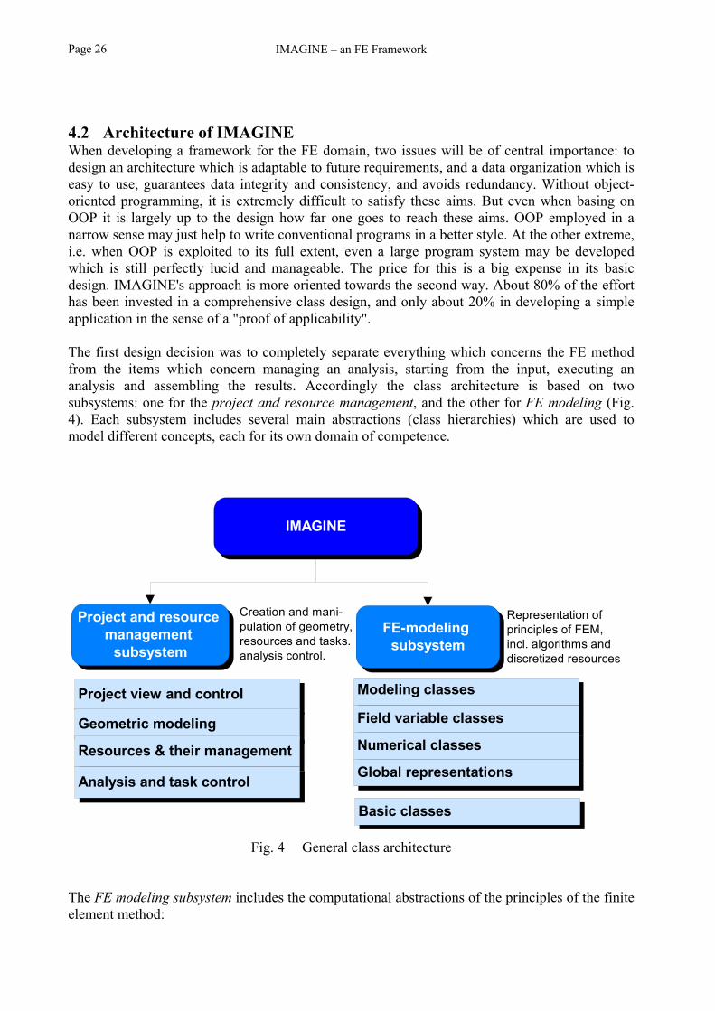
IMAGINE – an FE FrameworkPage 26
4.2 Architecture of IMAGINEWhen developing a framework for the FE domain, two issues will be of central importance: todesign an architecture which is adaptable to future requirements, and a data organization which iseasy to use, guarantees data integrity and consistency, and avoids redundancy. Without object-oriented programming, it is extremely difficult to satisfy these aims. But even when basing onOOP it is largely up to the design how far one goes to reach these aims. OOP employed in anarrow sense may just help to write conventional programs in a better style. At the other extreme,i.e. when OOP is exploited to its full extent, even a large program system may be developedwhich is still perfectly lucid and manageable. The price for this is a big expense in its basicdesign. IMAGINE's approach is more oriented towards the second way. About 80% of the efforthas been invested in a comprehensive class design, and only about 20% in developing a simpleapplication in the sense of a "proof of applicability".
The first design decision was to completely separate everything which concerns the FE methodfrom the items which concern managing an analysis, starting from the input, executing ananalysis and assembling the results. Accordingly the class architecture is based on twosubsystems: one for the project and resource management, and the other for FE modeling (Fig.4). Each subsystem includes several main abstractions (class hierarchies) which are used tomodel different concepts, each for its own domain of competence.
Fig. 4 General class architecture
The FE modeling subsystem includes the computational abstractions of the principles of the finiteelement method:
IMAGINE
Project and resource management
subsystem
FE-modeling subsystem
Project view and control
Geometric modeling
Resources & their management
Analysis and task control
Modeling classes
Field variable classes
Numerical classes
Global representations
Creation and mani-pulation of geometry, resources and tasks.analysis control.
Representation ofprinciples of FEM,incl. algorithms anddiscretized resources
Basic classes

Object-oriented design Page 27
modeling classes, e.g. FE types, nodes with information about geometry and elementconnectivity,
field variable classes, e.g. stresses and strains, degrees of freedom, numerical classes, e.g. templates of shape functions, global representations, e.g. the global discretized FE system, the equation solvers, and basic classes, vectors and matrices, points, and coordinate systems.
The FE modeling subsystem provides the necessary classes or data types to build acomprehensive representation of the underlying FE domain. However, the creation andmanipulation of the representation has to be done at another level. This level is often consideredto be the concern of user interfaces in graphics environments, or of macros or command parsersin conventional batch programming. In contrast, following the object-oriented philosophy thedecision which data or objects should be created should be delegated to the project control, andwhen to apply the loads to the task control. Both controls should be modeled as fundamentalclasses.
In IMAGINE this domain is realized in the project and resource management subsystem. Thissubsystem is considered to be equally important as the FE modeling subsystem. It includes the project view and control, which is responsible at the highest level for the views and the
control of the project, the geometric modeling, which is the intermediary between the geometry as defined by the
solid modeler and the one used by the FE modeling subsystem, the resources and their management, typically applied to zones or regions, and the analysis and task control, where the individual computing tasks are defined and the actual
computation is executed.
4.3 Project and resource management subsystem4.3.1 Project view and controlThe top level class of the architecture is class CFemProject. CFemProject is the abstraction of awhole FE analysis project: it "knows" everything about the geometry of the project, it has aresource database to store and query mathematical or engineering data like loads, constraints andmaterial properties; and it contains a set of tasks (e.g. Apply Loads) which can be used to executea complex computation which may depend on dynamically changing boundary conditions, e.g. amesh refinement based on accuracy criteria.
CFemProject class itself does not know anything about what kind of engineering project orphysical system it represents, nor about the type of resources and tasks it contains. This is theresponsibility of its derived specializations. Such specializations may be defined with regard tophysical field concepts (e.g. stress analysis, seepage analysis, etc.), or according to the modes ofthese fields (plane deformation, plane stress, etc., c.f. Fig. 5). Furthermore, specializations couldalso be based purely on engineering concepts, such as a "Tunnel Stress Analysis Project". Withthis approach a high level interface may be provided which directly corresponds to e.g. a tunnelproject and its construction procedure.

IMAGINE – an FE FrameworkPage 28
Fig. 5 Instantiation of an FE project
An important characteristic of a CFemProject object is that it keeps all member data of theproject, i.e. the project itself, persistent. In an application, CFemProject object can be saved andopened. While CFemProject does not actually implement the details of saving and restoring, itorchestrates all other objects it contains to do the job thanks to the serialization mechanism of theMFC.
Once a new derived class of CFemProject is defined in the code, it becomes a project templateand will automatically be listed as shown in Fig. 5. At any time during execution, there may beonly one project object instantiated. However, one can always edit the current project, open apreviously saved one or create a new one based on the template.
CFemProject abstracts the domain of the data of a project, together with its manipulations. Thisdomain is completely separated from the view of the data. In this context, view comprehends notonly organizing the actual display of the data, but also receiving and forwarding all userinteractions which could change the display either directly or by changing the underlying data.The view concept of IMAGINE relies on the Document-View Concept of the MFC (c.f."Appendix 3: The Document-View Concept of the MFC"). The basic classes participating in thisconcept may be seen from Fig. 6.
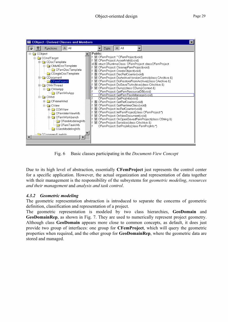
Object-oriented design Page 29
Fig. 6 Basic classes participating in the Document-View Concept
Due to its high level of abstraction, essentially CFemProject just represents the control centerfor a specific application. However, the actual organization and representation of data togetherwith their management is the responsibility of the subsystems for geometric modeling, resourcesand their management and analysis and task control.
4.3.2 Geometric modelingThe geometric representation abstraction is introduced to separate the concerns of geometricdefinition, classification and representation of a project.The geometric representation is modeled by two class hierarchies, GeoDomain andGeoDomainRep, as shown in Fig. 7. They are used to numerically represent project geometry.Although class GeoDomain appears more close to common concepts, as default, it does justprovide two group of interfaces: one group for CFemProject, which will query the geometricproperties when required, and the other group for GeoDomainRep, where the geometric data arestored and managed.

IMAGINE – an FE FrameworkPage 30
Fig. 7 Geometric modeling abstraction
The actual geometry organization and representation is encapsulated within classGeoDomainRep. This is in fact a huge subsystem. It is one of the main topics in the CAD/CAEfield. It has been abstracted so that it may be extended by means of derived classes with newemerging geometric representation models.
The most important competencies of GeoDomainRep are the capabilities of querying, computingand spatial decomposition. "Querying" refers to the capability of all geometric objects to bequeried quickly on demand. "Computing" allows the determination of geometric quantities likevolume, area, and center. The most demanding capability is the spatial decomposition. Here,spatial decomposition means the spatial subdivision into a regular mesh. This may also bereferred as the process of automatic mesh generation.
To be as general as possible for both 2D as well as 3D problems, geometry is expressed as a solidmodel. A solid is a bounded, closed subset of the 3-dimensional space. Solids may be modeled byBoundary Models, Constructive Models or Decomposition Models. IMAGINE relies on theBoundary Model approach. For this a solid is represented by its boundaries (faces), the faces bytheir edges, and the edges by vertices. Boundary Models are typically created by sweeping 2-dimensionals faces, and by unifying, intersecting and subtracting individual solids. From theuser's perspective the Boundary Model approach is especially suited for graphical constructions.From the programmers perspective boundary models are prime candidates for an object-orientedapproach.
In the course of the IMAGINE project an independent solid modeler was developed whichapplies the theory of Mäntylä (1988) to OOP. This modeler could serve in the future to integratein IMAGINE the possibility to quickly define the geometry based on predefined templates (e.g. acut-and-cover tunnel). On the other hand, all 3rd party solid modelers can be used (e.g. AutoCAD,MegaCAD) which export their data as a face/edge/vertex structure.

Object-oriented design Page 31
a) Geometry of QuadtreeRep object b) Mesh of QuadtreeRep object
c) Geometry of a SuperElemRep object d) Mesh of a SuperElemRep object
Fig. 8 QuadtreeRep and SuperElemRep approaches
However, to our knowledge, up till now no algorithm for automatic FE mesh generation exists forthe boundary model data structure. Therefore, although GeoDomainRep may read the geometryaccording to the Boundary Model approach, it is responsible to convert it to a form accessible forautomatic mesh generation engines.Currently two derived classes of GeoDomainRep for 2D domains have been developed whichdiffer basically by their automatic mesh generation algorithms adopted: QuadTreeRep andSuperElementRep.The QuadtreeRep model adopts a quadtree spatial subdivision algorithm according to Müller etal. (1991) and allows a fully automatic mesh generation, including local refinement andunrefinement, without creating elements with obtuse angles.

IMAGINE – an FE FrameworkPage 32
The disadvantage of this approach is that for the moment it could not be made universallyapplicable for all problems in geotechnical engineering. Mesh generation engines usually workvery well in the domain for which they have been developed, e.g. for semiconductor modeling.However, the "specialty" in geotechnical engineering is that very slim structural components withhigh stress gradients (e.g. a tunnel lining) are in the immediate vicinity of huge components (e.g.the rock mass itself) with only minor changes in their field variables. Therefore, the automaticmesh algorithms tested led to either too coarse a mesh for the lining, or to too many elements forthe surrounding rock.
Therefore, SuperElemRep has been added which relies on user specified superelements as inputdata. These may be defined in a way to avoid the problems mentioned above. The user may theninstruct IMAGINE to subdivide these superelements, leading to a very regular mesh fullycontrolled by the user. The drawback is that the initial geometry must be input in the form ofsuperelements. Fig. 8 illustrates the applications of these two classes.
Some practical consequences for the two representations will be discussed in 6.3 "Solid modelversus superelements".
4.3.3 Project resources and their managementAn FE run needs a variety of resources to completely specify a specific application problem.These may include material properties, loads, etc. Ultimately they must be known at thediscretized finite element level. This aspect will be discussed in the context of the FE modelingsubsystem.Here, in the context of the project and resource management subsystem, these resources aretreated at a higher level. E.g. a zone may be defined where certain characteristics apply. Thiszone is completely independent of the FE mesh, which at this abstraction level is not known.These resources will be called "project resources". The project resource objects are responsiblefor creating and manipulating their "discrete" counterparts after the FE mesh has been generated.
Project resources are modeled by IMAGINE in the FemResource class hierarchy (Fig. 9), andinclude: zone attribute resource: defines the type of a zone and its associated material resources. The
material resources themselves will be abstracted as a material resource class. The possiblezone types may be structured according to the project specialization. E.g. a tunnel project mayhave zone resources designated as Rock Zone, Lining Zone and Joint Zone. Although severalzones could share the same material object, their mechanical abstraction could be different,e.g. the element types and hence the element stress-strain matrix could be different.As default, a zone attribute resource will be defined for an entire solid or superelement,depending on the geometric modeling (GeoDomainRep) of the project.
material resource: a material resource is a composite resource: it contains material propertyresources and material law resources. The admissible material property types and material lawtypes for a project are compiled according to its host zone types. A material resource objectcan be referenced by several zone attribute resource objects.

Object-oriented design Page 33
a) Architectural resource classes b) Examples: specifications of project resources
Fig. 9 Resource class hierarchy
material property resource: used to represent any physical material property. The materialproperty may be an individual value like an elastic modulus, a cohesion, or a permeability, ora set of properties. Some useful material property resources have been predefined includingIsotropicContinuumProperty, StrataContinuumProperty, HeatConductivity, Permeabi-lity, Granularity, etc. Not all defined material properties will be used for a specific project.The relevant properties depend on the chosen project specialization and active zone types. Fig.10 shows the visible material property types in a generic plane deformation project. A material property resource object is one component of a material resource object.
a) Property dialog of a tunnel project b) Property resource hierarchy
Fig. 10 Material property resources

IMAGINE – an FE FrameworkPage 34
material law resource: used to model constitutive laws of a material. The programmer iscompletely free to place here any material model at the user's disposal.When and how the material laws will be used during a computation is considered to be theconcern of the project view and control (c.f. FemTask in section 4.3.4 "Analysis and taskcontrol").
load resource: here the term "load" stands for a broader concept. E.g. for a deformationanalysis, it stands for forces.Subclasses of load resource should be derived to meet the needs of the project specializationand the geometric model employed. Examples of loads specific to rock engineering projectsare DeadZoneLoad, and ExcavationEquivalentLoad. Examples of loads based on thegeometric model are ConcentratedForce, DistributedForce or BodyForce.
homogeneous constraint resource: the specification of the essential boundary conditionconcept of partial differential equations is abstracted as a constraint resource. The guidelinesfor derivations are similar to those of the load resource. Constraint resource objects can beintroduced at vertices, along edges or on faces. An example of a homogeneous constraint isfixed support.
heterogeneous constraint resource: the heterogeneous counterpart of homogeneousconstraint resource. An example of a heterogeneous constraint is a vertex with prescribeddisplacements.
coordinate system resource: a mathematical concept. It is universally useable regardless ofthe project type. Examples are RectCoordSystem, PolarCoordSystem, and Cylinder-CoordSystem. Once a coordinate system is created, it can be used by other resource objects.
These resource classes are called architectural classes since more specific classes can be definedfor a specific type of project.Already now, some more resource classes have been defined. E.g. a node group resource and anelement group resource: they are used to group nodes and elements in terms of geometric entities.
A resource objects manager has been developed. It controls resource objects according to theirclassification but does not know anything about the exact subclassing system.Resource objects are stored and managed by a resource database. This is a simple object databaserather than a relational database, since objects are in the center of interest but not tables andrecords. Each project contains just one resource database.Because all resource classes have the common ancestor class FemResource it is possible toderive more resource classes if needed, without requiring any additional steps. The reason is thatfrom a management point of view the resource database is responsible for the FemResourceobject only, but not directly for its derivations or any implementation details.A set of common interfaces has been defined to cover the communication needs between theresource classes and the resource object manager, and between the resource object manager andthe host project object.
The class hierarchies for the geometric modeling domain and the resource domain represent apowerful abstraction and contribute to a welcome separation of concerns for the whole project.The geometry and all resources of the project may be defined completely independently of the FEmesh, and thus provide e.g. a solid foundation for a fully automatic adaptive analysis even withcomplex geometric profile and boundary conditions.

Object-oriented design Page 35
4.3.4 Analysis and task controlConventionally an FE analysis has been split into three parts. In the pre-processing phase allinput data, i.e. geometry and other resources, are assembled. The actual computation solves theproblem described by the input data. And the post-processor analyzes and displays the results.While this is a natural division according to the working sequence, there is one more part whichis less apparent but usually included automatically during the program design: the so-calleddriver part, which controls the flow of the computation.The simplest driver program just calls a set of functions in a predefined order, such as applyingconstraints, applying loads, assembling the stiffness matrix and solving the equation system. Inorder to offer users the possibility to control the execution flow, many FE packages, e.g. RHEO-STAUB (Fritz, 1983), embed a macro-style command language. With this users may establish akind of flowchart to simulate a complex engineering process.
IMAGINE regards the analysis and task control as an important part of the project andmanagement subsystem. It is therefore abstracted into its own class hierarchy. At the uppermostlevel reside the classes FemAnalysis, FemTask and FemTaskCmd. They are differentiatedaccording to their level of abstraction: FemAnalysis controls an analysis at the engineering level,FemTask contains the individual tasks which can be executed by FemAnalysis, andFemTaskCmd contains the actual commands how to execute the task.
FemAnalysis has the role of a control center. It sends messages to initialize and record thesystem state at its various stages, it communicates with other key components of the project likeFemStruct, FemSolver and ResourceManager. The principal responsibility of FemAnalysis isto fetch the required FemTask objects and to dispatch them Fig. 11.
The name FemAnalysis was chosen so that its subclasses might be derived and named after theclassification of conventional analysis, such as ElasticAnalysis, ElastoplasticAnalysis,TunnelSeepageAnalysis, etc. Each new subclass of FemAnalysis signifies a new analysis type,something which would probably lead to a new program under conventional conditions.These subclasses are effectively responsible for manipulating the system state, because it dependson the analytic features considered. For linear problems, a snapshot of the current system state
suffices, for non-linear problems with pathdependence, probably the system states haveto be stored for initial, incremental and finalconditions.
Fig. 11 Example of an analysis flow

IMAGINE – an FE FrameworkPage 36
FemTask contains the individual tasks which may be executed by FemAnalysis. The individualFemTask objects are part of FemAnalysis and are therefore modeled in their own classhierarchy (Fig. 12).
a) FemTask class hierarchy b) Example of an Initialization Task
Fig. 12 FemTask abstraction
The key responsibilities of class FemTask are: to provide a set of common task data types that may be shared by different subclasses of
FemAnalysis. E.g. an "elastic computing task" may be used by all deformation analysisclasses.
to combine a set of control events reflecting the underlying engineering background. This isbased on the fact that often several numerical modeling steps are needed to model a singleengineering step. It would therefore be advisable to combine such numerical modeling eventsin an autonomous analytic task. An example of such a task for an analysis of a cut-and-covertunnel may be identified as "NextLayerTask" which may contain control steps like flush theprevious load, determine the interface nodal loads due to the weight of the soil layer,compute, and update.
to provide services for initialization and termination which may be needed for a task. Anexample is the "Inherit" service shown in Fig. 13, where an " initialization " dialog is used toprepare the initial state of a computing task.

Object-oriented design Page 37
Fig. 13 Example of a Task Initialization
FemTaskCmd contains the actual commands or events which may be used by FemTask tofulfill its duty. One may develop and add as many events as necessary to support FemTask andFemAnalysis through subclasses. A default set of FemTaskCmd subclasses has been abstracted(c.f. Fig. 14) including:
Fig. 14 Analysis-Task command classes
geometric control commands: to activate and inactivate geometric regions or element groups. load control commands: to apply and release loads. constraint control commands: to apply and release constraints. material property reset: to modify material properties. computing commands: to specify a material law, a computing type and update options. output commands: to output desired results at a macroscopic level.
In IMAGINE FemTaskCmd is normally not assumed to directly create FemResource objects asdiscussed in previous sections. Instead FemTaskCmd object uses the appropriate FemResourceobjects in the resource database of the project. It sends them a message through the virtual

IMAGINE – an FE FrameworkPage 38
function "Execute" which in turn will call a virtual function, in case of CmdSteeringLoad,"Apply" or "Release" to modify a FemStruct object. One of the exceptions of this rule isCmdCompute, for which no corresponding computing resource concept exists. In this case thevirtual function "Execute" of CmdCompute simply makes a callback to the virtual function"Compute" of the host FemTask object to execute the task.
4.4 FE modeling subsystem4.4.1 OverviewThe finite element method is a numerical tool with nearly unlimited power. While the generalprinciples of FEM remain the same, the actual solution approaches may greatly differ from oneengineering domain to another. It is practically impossible to enumerate them.When designing IMAGINE it was tried to satisfy the two contradictory requirements: on the onehand, to provide as much power as possible for the application domain envisaged, and on theother hand to make the design as general as possible. IMAGINE is clearly positioned to fulfill therequirements within the domain of Geotechnics only. Its generality goes as far as necessary to beextendable for future requirements within this domain, but not further, to avoid unnecessaryoverheads.
The FE modeling subsystem is the second leg of the IMAGINE framework. It is responsible forthe abstractions of the general concepts of FEM. These mainly include the general principles, thedata representations, and the geometric and topologic concerns of the discretization. Specialefforts have been made to cover future extension requirements. Examples of this may beextensions to include complex material models (c.f. Fritz, 1983), structural complexities (joints,lining), and field coupling (e.g. seepage-deformation), etc.
The FE modeling subsystem should not be understood just as a data structure as it would be inconventional approaches, nor as a black box of invariant components of IMAGINE. It is anintegrated part of the whole framework. Its usefulness to develop subclasses of CFemProject,FemResource, FemAnalysis and FemTask all depends on the availability, capability andextendibility of this subsystem.
The FE modeling subsystem defines a set of generic architectural classes. Each architectural classabstracts a specific part of FEM. The fundamental problems of the transitions between global andlocal formulations specific to FEM are also dealt with at this level.A simple FE application could be built just with the generic architectural classes. For moreadvanced applications subclasses of the generic architectural classes may be derived which makeavailable required extensions. However, since most of the fundamental concerns, such as elementanalysis, local-global indexing, loading, associations between field variables, and storagemanagement, etc., are covered as defaults by the generic classes, when developing an applicationone may concentrate on those features only which are relevant for the specific application.

Object-oriented design Page 39
4.4.2 Modeling classes and field variable classes
4.4.2.1 Overview
The physical side of FEM is governed by differential equations which are based on twofundamental elements: the definition domain (e.g. finite elements, supports), and the physicalfield variables which act in this domain. Consequently, the numerical model for the physicalengineering problem, from an object point of view, may be composed of two groups ofabstractions: modeling classes and analytic or field variable classes.
When applying FEM to solve PDEs, the geometry domain is discretized into a mesh. An equationsystem is built for a set of ordered field variables at the mesh points and solved simultaneously.Thus basically the modeling classes serve for building the system of equations, the results of itbeing placed in the field variable classes.
For a continuum, the modeling classes mainly refer to the classes which are necessary for thediscretized representation of field variables, and classes which are used to interpolate fieldvariables. In terms of FEM, these may include the mesh, elements, nodes, shape functions andinterpolation functions, etc. Conceptually they are related to the interpolation theory and thespatial discretization principle, which are common to all physical application types. In an object-oriented design they form the highest abstraction level of an FE application.
Usually an FE modeling system is implemented specifically for a well-defined physical field,such as a seepage problem or a deformation problem, where the physical background of themodeling concept and the corresponding field variables are clearly related and simple. They maybe combined together to form so-called element formulas. The “Degree of Freedom” (DOF)class, for example, may naturally refer to the primary field variables of the underlying physicalfield, such as nodal displacements, without any ambiguity. The secondary field variables (e.g.stresses or strains), which are normally locally computable through interpolation of primary fieldvariables, may be defined on demand and computed using the values of DOF without the need offurther interpreting their type.
However, it would be a great advantage if an FE framework could offer the possibility to developapplications for different physical engineering problems. Such a feature would especially beuseful in the field of geotechnical engineering. This can be verified immediately by viewing thelist of demanding research topics in geotechnical engineering: stress analysis problems,groundwater flow problems, swelling problems and convection problems, which require takinginto account the coupling of deformational, hydraulic and thermodynamic problems.
The design of an FE framework with configurable field variable types requires a complete reviewof the original theory of FEM. An immediate consequence is that the element formulas are nowno longer constant even if the element shape and interpolation functions remain the same, sincethe element formulas are derived from a given field variable type. This may suggest derivingelement types for the individual field variables or combinations of them. Each subclass of thegeneric element class would be defined specifically for a certain field type, such as a LaplaceElement, a Deformation Element, etc., just similar to the widely used structural elements, liketruss and beam elements. Since element formulas are just one of the concepts which are related tofield variables, other class hierarchies would have to be defined in a similar manner, e.g. for
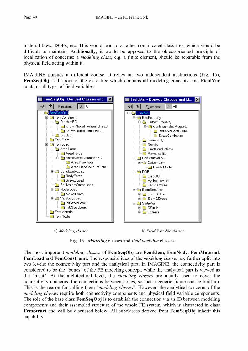
IMAGINE – an FE FrameworkPage 40
material laws, DOFs, etc. This would lead to a rather complicated class tree, which would bedifficult to maintain. Additionally, it would be opposed to the object-oriented principle oflocalization of concerns: a modeling class, e.g. a finite element, should be separable from thephysical field acting within it.
IMAGINE pursues a different course. It relies on two independent abstractions (Fig. 15),FemSeqObj is the root of the class tree which contains all modeling concepts, and FieldVarcontains all types of field variables.
a) Modeling classes b) Field Variable classes
Fig. 15 Modeling classes and field variable classes
The most important modeling classes of FemSeqObj are FemElem, FemNode, FemMaterial,FemLoad and FemConstraint. The responsibilities of the modeling classes are further split intotwo levels: the connectivity part and the analytical part. In IMAGINE, the connectivity part isconsidered to be the "bones" of the FE modeling concept, while the analytical part is viewed asthe "meat". At the architectural level, the modeling classes are mainly used to cover theconnectivity concerns, the connections between bones, so that a generic frame can be built up.This is the reason for calling them "modeling classes". However, the analytical concerns of themodeling classes require both connectivity components and physical field variable components.The role of the base class FemSeqObj is to establish the connection via an ID between modelingcomponents and their assembled structure of the whole FE system, which is abstracted in classFemStruct and will be discussed below. All subclasses derived from FemSeqObj inherit thiscapability.

Object-oriented design Page 41
The physical field variable components in IMAGINE are modeled as a set of field variablearchitectural classes with the following main components: DOF, StateVar, ElemStateVar,BasProperty and ConstitutiveLaw. Again, at this level, each of them only addresses the genericconcept it represents. Subclasses may be developed to model effective components. All the fieldvariable classes are derived from the base class FieldVar. One important role of FieldVar is tocover the association requirements of its subclasses. The need to model associations of fieldvariables is less apparent if there is only one type of field variables. For example, if theframework is limited to simple elastic deformation, then DOF must be displacement, StateVarmust be Stress and Strain, and MaterialProperty probably holds two values, the elasticmodulus and Poisson's ratio. However, the association concept becomes important when DOF,StateVar, and BasProperty each abstracts a hierarchy.In IMAGINE all objects of type FieldVar are given an ID attribute which gives information onthe type of the field variable, and a list of IDs which gives information on associated fieldvariable types. A field variable type ID is not a class ID. It is based on the classification ofphysical field types and field variable types. It is not a unique ID to identify a class type, butrather a unique key to identify the field variable type. The type ID of a class may serve to makesome advanced features such as object persistence possible. The field variable type ID, however,provides a way to ensure that the manipulations of field variable objects are physicallymeaningful so that, for example, a strain object could only be computed from a displacementobject, but from no other kind of field variable.
The field variable type IDs are based on the classifications or computational abstractions ofphysical field variables. Currently, seven entries for physical field variables are defined which arethe most fundamental physical field variables from a computational point of view. Each entryrepresents a type of field variable. The field variable types are FemFieldVarID (physical field type, e.g. deformation problem), FemNodeDOFID (DOF type, e.g. displacement), FemElemVarID (state variable type for FemElem, e.g. ElemGStress), FemStateVarID (state variable type, e.g. GStress), FemMaterialPropertyID (fundamental material property type, e.g. DeformProperty), FemMaterialLawID (material law type, e.g. DeformLaw), FemFieldCharacterID (character of physical field type, e.g. PlaneStrainMode).
Every subclass of FieldVar will either inherit or be assigned a field variable type ID in order tobe identified by its associated FieldVar classes. In addition, every subclass of FieldVar willeither inherit or be assigned a set of associated field variable type IDs in order to access theobjects of its associated FieldVar classes. Users of the framework can decide on and providethese IDs if a new set of field variables is introduced.

IMAGINE – an FE FrameworkPage 42
4.4.2.2 Element concept
The procedure to build a discretized FE representation of an engineering problem may be viewedfrom two perspectives: from the global or structural perspective, and the local perspective atelement level. Examples of global level concern are the ordering of DOFs and the assembly ofthe system of equations. Examples of element level concern include information about elementgeometry and topology, and local mathematical and physical characteristics analysis.The treatment at the element level is also called element analysis. Mathematically, the purpose ofelement analysis is to provide a set of formulas, the so-called element formulas. Elementformulas differ from element-to-element, depending on the element’s geometric shape, theinterpolation functions, and the field variables of concern. Often a specific element configurationis referred as element type, such as truss element or beam element, which are named after theirmechanical behavior, or triangle element, which is named after its geometric shape. Numerically,following a conventional approach, often a set of separated routines must be developed to handlethe calculations of a specific element type at different stages.
On a first look, the introduction of an element data type (or class) when using OOP is expected tobe a straightforward matter. However, on a second look it is recognized, that the design of suchan abstraction is not obvious and could lead to a bunch of different approaches. At a first glance,it appears that element data types could be constructed according to the "element type" conceptmentioned above. And effectively this approach could be used with certain element types like atruss, beams, or even simple shells. However, difficulties would appear integrating furtherextensions or configuration changes, such as general material models or new shapes, due to thelack of abstraction and separation of concern. Such an approach requires that for any possiblecombination of shape, material and field variable type, a new element data type has to be derivedand many common operations like shape function derivatives have to be duplicated. This isobviously not the way to fulfill the promises of OOP techniques.
As a matter of fact, the responsibilities at the element level rely on a composite concept. It is aduty of a correct design to separate as far as possible the concepts that a generic element type iscomposed of. IMAGINE takes into account the following independent concepts: connectivity,geometric shape and shape functions, numerical integration, element field variables, materialresponse, and coordinate system.
The base class of the element hierarchy is FemElem (Fig. 15a), which is derived fromFemSeqObj. FemElem is an abstraction of a generic element. It is configurable in terms ofCoOrdSys, FemShape, FemMaterial, ElemStateVar, etc. The primary responsibility ofFemElem at this level is to provide coordinates and connectivity information through its node listto the outside. This includes also the geometric subdivision of an element.Other capabilities of FemElem may be considered as open issues. The objects representing thesecapabilities will be created externally and bound to FemElem dynamically. Several Elem-StateVar objects representing different field variable types are allowed to be linked.
Additionally, the basic interface between the local element level and the global structural level isdefined in FemElem at an abstracted level. It is a set of mostly virtual functions which get theircontent from member objects.As default, FemElem assembles the information returned from its member objects, such as theinterpolation scheme, geometric derivative matrix B and material matrix D to form inherent

Object-oriented design Page 43
element properties, such as element stiffness matrix and element nodal force vector, usingstandard element analysis formulas. At this level, FemElem does not know which "element type"it is. If required, subclasses may be derived to form "strong typed" element data types, which areless flexible, such as JointElement or LiningElement. Since many common capabilities arecovered by higher level classes, these subclasses may concentrate on "what to do" rather then"how to do it".
Other capabilities of FemElem, e.g. how numerical integration is done, will be mentioned underthe topic "Numerical Classes".
Point state variables versus element state variables:As mentioned above, in IMAGINE field variables are abstracted in the class hierarchy FieldVar.The primary field variables are captured with DOF class hierarchy which will be discussed later,the secondary field variables, such as stress, strain, moment, rotation, heat and flow rate andgradient, are abstracted as subclasses of the two class hierarchies StateVar and ElemStateVar,as shown in Fig. 16.
StateVar is the abstraction of a secondary field variable, such as stress or strain. It is defined at ageometric point. It is mainly used for various mathematical operations related to the statevariables themselves, but not related to the element concept.
For each StateVar subclass, there is a corresponding ElemStateVar subclass. ElemStateVarand its subclasses are the enhancements of their counterparts in terms of elements. Theenhancements are considered to be necessary, based on the following considerations: firstly,element is the basic unit from the structural point of view. The integration points are consideredto be the internal affairs of the elements only. It is therefore more logical to store and access thestate of elements in terms of element values rather than in terms of point values. Secondly, withthis approach the high level modeling class FemElem is released from managing the StateVarhierarchy.
Both StateVar and ElemStateVar are derived from FieldVar and must therefore be able to beidentified through unique field variable IDs.

IMAGINE – an FE FrameworkPage 44
Fig. 16 Derived state variables
The subclasses of ElemStateVar, e.g. ElemGStress or ElemGStrain, carry a "G" in their nameswhich stands for "generic". I.e. subclasses must be defined to allow instantiation. An importantresponsibility of the subclasses derived from ElemGStrain is to provide the B matrix whichyields a " strain" from a "displacement" by interpolation over an element. This B matrix is usedfor the element analysis, e.g. for the calculation of the element stiffness matrix, or the calculationof "strain" from "displacement". All the subclasses of ElemStateVar are linked to appropriateDOF types and material properties through so-called association keys.
The class FemElem is designed to keep a list of ElemGStress objects and a list of ElemGStrainobjects in order to allow handling of coupled problems.

Object-oriented design Page 45
4.4.2.3 Node and degrees of freedom (DOF) concept
The class FemNode (c.f. Fig. 15a) is used to model the node concept of a discretized finiteelement system. Similarly to FemElem, due to its extensive separation of concerns, it hascurrently no subclasses. It derives its power from a multitude of aggregate objects and memberfunctions.As default, the properties of a FemNode include: coordinates, a list of DOF objects, connectivityinformation, the values of primary nodal field variables, and the values of generic nodal loads.
The location of FemNode is represented by an object of IgtPoint. The connectivity propertyrefers to the information regarding which elements are connected to the node. The values of"generic" primary field variables and loads are represented by a vector. The vectors aresubdivided and arranged by DOF objects.
Fig. 17 DOF class hierarchy
The concept of the degrees of freedom at a node of a discretized finite element system isintimately related to the node concept. The DOF concept as introduced by IMAGINE (Fig. 17)should not be interpreted as the "number of degrees of freedom". DOF and its subclasses containinformation about how many unknowns associated with a certain type of field variable apply in aFemNode, the state of these unknowns ( free or constrained) and their indices in the discretizedFE system. A local coordinate system will be provided wherever it is necessary since in practicethe DOF objects sometimes may only be defined relative to a local coordinate system (e.g. forconstraints applied at an inclined support).Encapsulating DOF in a separate class allows hiding implementation details and changing theirtype and properties dynamically. As mentioned above the DOF class hierarchy contains theprimary field variables (e.g. displacements), whereas the secondary field variables (e.g. strain)are contained in the two class hierarchies StateVar and ElemStateVar.
The class hierarchy DOF is derived from FieldVar, i.e. it also falls into the model of ID key andassociated ID keys which should be provided by the DOF subclasses.Each class of DOF class type returns an ID which is defined in the FemNodeDOFID field ofclass FieldVarID. Currently, three physical field types are considered: deformation, heat transferand groundwater flow. Accordingly the DOF IDs returned are Disp, Temperature orHydraulicHead.

IMAGINE – an FE FrameworkPage 46
Instead of defining DOF for all degrees of freedom at a node, an DOF is defined for eachindividual field variable type. This means a node may contain a list of DOF objects with differentfield types (e.g. for a coupled problem), and an individual DOF object can be accessed by itstype. The subclasses of DOF are related to the actual physical background.
4.4.2.4 Load concept
The term "load" may be defined from a physical or a mathematical point of view. From aphysical point of view loads are given by some boundary conditions and change the state of themechanical system. The actual physical instantiation of a load is highly problem-dependent. Inthe case of deformation problems, it may be some kind of force. From a mathematical point ofview loads appear on the right hand side of the linear equation system.
The class FemLoad (c.f. Fig. 18) and its subclasses are used to represent the generic "load"concept mentioned above. The load classes are first hierarchically structured according togeometric characteristics: NodalLoad concerns concentrated loads. ArealLoad representsdistributed loads over element borders. BodyLoad captures distributed loads along elementboundaries. Since these features are common to all types of loads regardless of the physicalbackgrounds, they are also considered to be generic classes of the IMAGINE framework. Further,derived subclasses are forced to take physical significance into account. In the case ofdeformation problems, the subclasses may be NodalForce, ArealForce, and GravityForce.
Fig. 18 FemLoad hierarchy
The load classes contain information such as where, what and how to apply themselves to thesystem, usually to FemNode objects. They are connected to the system by being derived fromFemSeqObj. They are linked to appropriate DOF objects through the IDs returned from thevirtual function getJointNodeDOFID.

Object-oriented design Page 47
Each object of FemLoad is capable of handling a group of actual loads applied to a group oftarget objects, as long as the loading specifications remain constant.
4.4.2.5 Constraint concept
The term "constraint" refers to the essential boundary conditions of the governing PDEs of anengineering physical problem. In the case of deformation problems, constraints describe theknown boundary displacements.
The abstraction of the constraint concept is done similarly to that of FemLoad. Firstly, aFemConstraint (Fig. 19) is derived from FemSeqObj as a generic constraint data type, which isresponsible for "where" to apply the constraints, the subclasses then handle the issues of to"what" and "how" they should be applied. As default, the constraints will be imposed on DOFobjects.
Fig. 19 FemConstraint class hierarchy
Mathematically, there are two different types of essential boundary conditions: homogeneous andheterogeneous. A constraint is said to be homogeneous when it is zero, otherwise it isheterogeneous. In the case of deformation, the term "constraint" normally refers to thehomogeneous ones (i.e. zero displacement), while "prescribed displacement" refers toheterogeneous boundary displacements. Heterogeneous constraints are often considered to beexceptions and to require special treatment both locally and globally. The local treatment thatevaluates the contributions of heterogeneous constraints to the "load" vector is handled byFemConstraint through the virtual function convertToLoad. The global treatment is not aconcern of FemConstraint.
The class FemConstraint has a knowledge of the underlying coordinate system. The constraintsof a FemConstraint object are considered to be relative to a specific coordinate system. Asdefault, the coordinate system coincides with the global coordinate system. If the constraints of aFemConstraint object are not relative to the global coordinate system, information about thelocal system will then be transferred to the target objects (e.g. DOF objects) together with theconstraints.

IMAGINE – an FE FrameworkPage 48
4.4.2.6 Material concept
FE applications can usually be classified according to the type of the governing PDEs, andaccording to the material behavior. Often, the introduction of a new material model yields acomplete new research branch, both mathematically and numerically, even if the underlyingPDEs remain the same. Examples hereof are elasticity, elasto-plasticity, and general rheologicbehavior.
In OOP, the material behavior forms an independent level of other FE classes: in a strict sense itneither fits in the project and resource management subsystem nor in the FE modeling subsystem.The reason is that the concept of the material behavior is actually not a part of the principles ofFEM, but rather of system states. In fact, the material concept could have been separated from theFE modeling subsystem and integrated into a new subsystem. The main reason not to do that butto leave it in the FE modeling subsystem was to make it more convenient for other objects of theFE modeling subsystem to correspond with it.
a) Constitutive law b) Material properties
Fig. 20 Material concept
The abstractions of the material concerns lead to several class hierarchies in IMAGINE: ageneric material data type FemMaterial (Fig. 15a) in the modeling class hierarchy, and amaterial constitutive law hierarchy ConstitutiveLaw and a material property hierarchyBasProperty in the field variables hierarchy as shown in Fig. 20.
The class FemMaterial serves as a container for material properties and constitutive laws.Various types of material properties and laws can be defined and linked. According to the currentdesign, FemMaterial is a kind of architectural class for FE modeling, while materialConstitutiveLaw and material BasProperty are kinds of architecture classes pertaining to fieldvariables.Since class FemMaterial is derived from FemSeqObj it inherits the integrity of modelingobjects established by FemSeqObj. It is accessible directly by other modeling objects. Theobjects of ConstitutiveLaw and BasProperty can be accessed with their FemMaterialLawIDand FemMaterialPropertyID.

Object-oriented design Page 49
Because a given application domain may contain several material laws for each computationalstep, several material laws may be stored in the FemMaterial object. However, all the FieldVarobjects and even class FemStruct will ignore which material law should be applied and when itshould be activated. The material concept as it is implemented in IMAGINE is tightly connectedto the concept of computing tasks as modeled by the classes FemAnalysis, FemTask andFemTaskCmd.
A material may have many physical properties, e.g. deformation properties, permeability, heatconductivity, gravity, granularity1. They are material attributes and measurable under normalconditions. These basic properties are abstracted with class BasProperty and its derived classes.The class BasProperty itself is one of the architectural classes for the physical field system. It isnot instantiable directly. More detailed information, such as property type and property constants,are supposed to be the responsibilities of its subclasses. Fig. 20b) shows the current five directbranches of class BasProperty: DeformProperty, Permeability, HeatConductivity,Granularity, and Gravity. Other properties can be defined on demand.
The class ConstitutiveLaw and its derived classes are used to describe the physical relationshipof more complex material behavior than can be expressed with the basic properties.ConstitutiveLaw is derived from FieldVar. It is therefore also a kind of architectural class forthe physical field. Like other FieldVar classes, ConstitutiveLaw has its associated FieldVarclasses and can be accessed by other FieldVar objects through its field variable type ID. A set ofbasic interfaces to other objects of the FE modeling subsystem, such as D and C matrices, havebeen prototyped which are considered to be common to all material models. It is theresponsibility of the subclasses to implement them.
Normally, the behavior of a material depends on the state of the field variables and the pathwhich led to them. However, in IMAGINE it is not the responsibility of the material objects totrace this information, but rather the responsibility of CFemProject and FemAnalysis.
4.4.3 Numerical classesNumerical classes are primarily responsible for providing integration support for FemElem.In FEM, due to the mathematical complexity, element analysis (e.g. integration, derivation, etc.)is usually not done directly in the physical space of the element. Instead, some standard andregular element shapes are provided in a mapped space in form of standard shape templates. Eachelement template is defined by a set of shape functions. The shape functions depend on thedimensions of the mapped space, and the number of nodes of the shape template. Elementanalysis is then done in the mapped space and is subsequently remapped by means of coordinatetransformations.
1 In "granularity" the cohesion and the angle of friction are comprised.

IMAGINE – an FE FrameworkPage 50
In IMAGINE, the shape information, both geometrical and analytical, are abstracted and modeledby the FemShape class hierarchy, as shown in Fig. 21.
a) FemShape classes b) Numeric integration classes
Fig. 21 FemShape class hierarchy
The class FemShape and its immediate subclasses Fem1DShape, Fem2DShape andFem3DShape are defined as abstract classes, i.e. they just serve as generic classes which cannotbe instantiated. Derived classes of them are the actual shape templates which are responsible toprovide detailed information.
In addition to local geometric information, other important information that FemShape (and itssubclasses) is expected to provide is local topological information and local analyticalinformation.Local topological information include local indexed face-side-vertex structures. It is predefinedfor every shape template. This information is often needed to perform some kind of integrationover the boundaries of an element's shape template, e.g. the calculation of distributed loads.Local analytical information of a shape template refers to its shape functions and the derivativesof these shape functions at given points of the shape. The shape functions are predefined forevery instance of a shape using class ArrayPartial which is capable of returning the partialderivatives if the corresponding functions are given. From the viewpoint of element analysis, twoset of points of a shape template are considered of special importance: the integration pointswhich are needed to compute the element stiffness matrix; and the points where field variablesare computed. The numerical integration scheme, including the integration points and weights,are abstracted in class NumericInteg. Objects of NumerInteg are expected to be specified byusers (programmers) and used by FemShape. All the local analytical information is computedonly once at the integration points as long as the points remain unchanged.
The mapping information, such as the Jacobean determinant, can be computed when globalcoordinates are given. The nodal global coordinates are considered to be the concern ofFemElem and will be supplied by the objects of FemElem.

Object-oriented design Page 51
Once an element shape is defined which may be instanced, it can be used for all physical fieldproblems thus avoiding coding redundancy. Once an object of element shape is created, it will beshared by all element objects with that shape without repeated computation of local analyticalinformation for an element object, which leads to both programming efficiency and computingefficiency.
4.4.4 Global representationsSo far great effort has been made to separate the various responsibilities of FEM as much aspossible. A set of architectural classes at the local (discretized) level has been established whichaddresses the individual concepts of FEM. However, a discretized FE system is a discretizedrepresentation of the original PDEs for the overall (global) geometric definition domain. All thelocal objects are just parts of the global system and must be compiled to build up the globalrepresentation. The discretized FE representation in terms of local objects is abstracted in classFemStruct (Fig. 22).
Fig. 22 Representation of the discretized FE system in FemStruct
Class FemStruct is the abstraction of a generic FE system. The term "Struct" refers to thediscretized FE representation, not to the concept of an engineering structure, although FemStructcan be created as the discretized FE representation of an engineering structure.
The most important components of FemStruct are FemElem, FemNode and FemMaterial.IMAGINE is based on the requirement that the components are properly created outside of

IMAGINE – an FE FrameworkPage 52
FemStruct, because FemStruct has no knowledge neither about the type of an element, norabout the type of the physical variable acting in it. The creation and initialization of the objects isconsidered to be the responsibility of CFemProject (for element types, DOF types, state variabletypes, material property types, coordinates, etc.), which acts as the bridge between the originalgeometrical and physical specifications and the FE representation, and the responsibility ofFemAnalysis and FemTask (for loads and constraints, material laws), which specify variousboundary conditions and computational tasks. The sequence in which the objects are added toFemStruct is not significant.
Thanks to the complete separation of modeling components and field variable components ofIMAGINE, it is possible to create a FemStruct object with the complete information about thegeometry and topology of the discretized system, but without any field variable objects attachedto it. The field variable objects, such as DOF, ElemGStress, ElemGStrain, BasProperty,ConstitutiveLaw, etc., can be bound later to the FemStruct objects on the fly withoutinfluencing the topological structure of FemStruct. This may be useful for a case where onephysical problem has to be determined as the initial condition of another. As an example, the casemay serve where seepage forces act as loads for subsequent stress calculations.
The topologic relations are the main concern of FemStruct. These include element-node graphsand DOF numbering. The relations will be built or rebuilt by FemStruct after properinitialization or change of specific components. These relations may be completely hidden tooutside classes. E.g. optimization of node or element numbering schemes is considered to be theinternal affair of FemStruct.
FemStruct does not store any of the objects of FemLoad and FemConstraint. They are realizedas modeling classes in the sense of boundary conditions which are managed by FemAnalysis andFemTask. They are applied to FemStruct on demand. It is the responsibility of the taskscheduler to specify correctly which boundary conditions apply before solving the system.
Besides FemStruct, the other important class hierarchy which is responsible for global concernsis FemSolver (Fig. 23). It contains a hierarchy of various type of solvers, and all methods whichdepend on these types, including assembling the global stiffness matrix based on the local data ofFemStruct and solving the system of equations. Currently, just a basic skyline solver, arepresentative of direct solvers, is used. However, provisions have been made andimplementation has been started to include also iterative solvers, such as the conjugate gradientmethod (Crisfield, 1986). Iterative solvers seem to be especially well-suited to 3D problems orfor use in conjunction with an adaptive mesh refinement.

Object-oriented design Page 53
Fig. 23 Solver classes
4.4.5 Basic classesOften IMAGINE needs to manipulate, to operate on and to represent modeling objects likeelements and nodes and field variable objects like stress and strain. For this purpose, a set ofbasic matrix and geometric data types has been designed to cover fundamental geometric andalgebraic requirements, including: location and coordinate classes: IgtPoint, IgtCoOrd, PolarCoOrd, CylindCoOrd, coordinate system classes: IgtCoOrdSys, IgtOrient, data representation classes: IgtMatrix, IgtVector, IgtIndex.
The role of the data types representing coordinates and coordinate systems are obvious and needno special comments. E.g. IgtPoint abstracts a geometric location in space. It is transformable(from one geometric configuration to another) and operable (add, subtract, etc.). IgtCoOrdSys isused in classes FemElem, DOF, FemConstraint and FemMaterial to specify their own localcoordinate systems if required.
The design of the matrix classes requires some additional comments. Matrices are often classifiedaccording to their element distribution characteristics. Examples of this are triangular matrices,banded matrices, sparse matrices, symmetric matrices, etc. In order to save system resources andto promote computing efficiency, it is desirable that a matrix "knows" its type, how to store itsdata and how to execute common operations. Often OOP is cited as a good candidate to reachthese goals thanks to its inherent capability of data abstraction and polymorphism.
With respect to the size of the matrices, IMAGINE relies on two completely different matrixtypes. The global stiffness matrix is usually quite big (several thousand degrees of freedom),whereas the local matrices (such as coordinates, stress and strain vectors, and all the matricesneeded for the element analysis) are very small. The problems of these two matrix types arerather different. The main problems when working with large matrices are how to allocate andhandle storage (virtual memory!), and to find the most efficient solving algorithm according totheir data structure. Both problems are irrelevant for small matrices. However, here the mainproblem is to avoid unnecessary overheads for frequent allocations and deallocations of smallmemory chunks, something which in turn is not relevant for large-size matrices.

IMAGINE – an FE FrameworkPage 54
From a conceptual point of view it would be tempting to have a common matrix hierarchy thatcovers the concerns of all matrix types. Two arguments are opposed to this approach: Firstly, asmentioned above the demands on large and small matrices are completely different. Therefore,the corresponding classes would have just a very small common basis. Secondly, compatibilityrequirements between the different matrix types, e.g. automatic type conversions, would lead to alot of work and unnecessary overheads, which would then lead to inefficient algorithms.
Therefore, IMAGINE relies on two completely separated matrix concepts. Large matrices areused and handled in the context of FemSolver. Small matrices as needed for local operations areabstracted in the classes IgtMatrix and IgtVector.
IgtMatrix and IgtVector are used by many classes of IMAGINE: the FE modeling classes, fieldvariable classes, and the geometric modeling classes. They are designed to address the abovementioned concerns of small matrices.An effort has been made to avoid unnecessary allocation and deallocation overheads duringmatrix operations. Consider, for examples, the formation of the element stiffness matrix K = (~B)∗ D ∗ B where operator ~ stands for the matrix transpose. In C++, normally a temporary matrix(not pointer), say BD, will be allocated and initialized with the matrix returned from (~B)*D, sayreturnMatrix. The returnMatrix will then be deallocated. This kind of allocation-initialization-deallocation happens in all cases of matrix or vector operations that return a matrix or a vectordata type. Since the matrix or vector operations are intensively used in FEM, it is very importantto avoid the aforementioned redundant allocation-initialization-deallocation procedure. This maybe achieved by introducing a reference counter in class IgtMatrix and IgtVector to control theredundant allocation-initialization-deallocation. In the above case, the data representation of BDwill be linked to returnMatrix and inform returnMatrix that its data is referenced. The data ofreturnMatrix will not be deleted when the destructor of returnMatrix is called. In this way noredundant allocation-initialization-deallocation is taking place, thereby greatly enhancing thecomputing efficiency.
Example Page 55
5 Design and implementation of the user interface5.1 IntroductionIMAGINE is rather a framework than an application. Although it provides classes ranging fromFE modeling, meshing, solvers to task control, it does not give users the option of inputting dataand outputting results, as would be the case for an application.
With increasing size of framework, sometimes it is no longer so apparent why individual classeshave been provided and how they should be used. Therefore there is a strong need for apossibility which allows exploring the features of IMAGINE. Conventionally such a possibilityconsists of some simple example applications. However, because with IMAGINE a variety ofapplications can be implemented, we pursue another approach. An integrated modeling andcontrolling environment is presented which serves as a quite general and extendable userinterface for defining and running examples with IMAGINE. Its design follows closely thedesign of IMAGINE itself in order to demonstrate as far as possible IMAGINE's class layout andfeatures.
The aim of this modeling and controlling environment is twofold: first fulfilling the requirement,according to which three applications of a framework are necessary to validate its strategic andtactical decisions (Wirfs-Brock, 1990, cited by Booch, 1994).And second, perhaps more important, to demonstrate that the object-oriented design of theframework may also be (partly) continued for the user interface, in the sense that the user maychoose objects (e.g. a node) and subject them to methods (e.g. apply a load).
5.2 Workbench approach5.2.1 OverviewAs shown in Fig. 4 "General class architecture", IMAGINE is made up of two main subsystems.One is the project and resource management subsystem, the other the FE-modeling subsystem.
Each subsystem is structured into further subsystems. The project and resource managementsubsystem, for example, contains the subsystems project view and control, geometric modeling,resources and their management and task control. Of special interest with regard to the design ofthe user interface is the subsystem project view and control. It contains the root of the wholearchitecture, the class CFemProject, which abstracts the domain of all data of an FE analysisproject, together with its manipulations.
As mentioned above, this domain is completely separated from the view of the data. The viewconcept comprehends not only organizing the actual display of the data, but also orchestrating alluser interactions which could change the display either directly or by changing the underlyingdata. This concept relies on the Document-View Concept of the MFC (c.f. "Appendix 3: TheDocument-View Concept of the MFC").
Class CFemProject acts as the interface between the generalized data and their view. The viewitself is managed by so called workbenches. At the moment, three workbenches are defined: theGeometric Modeling Workbench, the Fem Modeling Workbench, and the Fem Task Workbench(see Fig. 24). The Geometric Modeling Workbench is used to define and edit the geometry of the

IMAGINE – an FE FrameworkPage 56
project by means of solid modeling. Currently, as outlined in section 3.7, external solid modelersare used instead of this workbench. In the Fem Modeling Workbench all the FE resources,including the mesh, may be defined and modified. The Fem Task Workbench provides a graphicseditor, in which the computational tasks may be defined and assembled into a kind of a flowchart.A fourth workbench, which could be added in the future could be used for postprocessing anddisplaying results. At the moment, this is delegated to third party software (see section 3.8).
Fig. 24 IMAGINE workbenches
Each workbench is abstracted by a corresponding class (Fig. 25). It may be seen, that the designof IMAGINE's workbenches follows closely the architecture of IMAGINE's design (c.f. Fig. 4).
Fig. 25 Workbench classes
CFemProject
GeoDomainRep layer Geometric Modeling Workbench
FemResource layer FEM Modeling Workbench
FemTask layer FEM Task Workbench

User interface Page 57
5.2.2 Kinds of workbenchesAn important task of each workbench is to provide the means for a straightforward definition ofresources. According to their domain of validity three classes of resources are distinguished: project resources, which apply at the "project level", where the geometry is described by a
solid model, a quadtree or a superelement representation, FE resources, which apply at the discretized "FE level", and task resources, which apply independently of the above mentioned levels for the analysis
directly.
Striking examples of project resources are obviously geometric data at the non discretized level,abstracted at its highest level by GeoDomainRep, but also modeling attributes which depend onlocation, as e.g. zones, material properties, loads and constraints, which are abstracted byFemMaterial, FemLoad, FemConstraint, etc.
Examples of FE resources are structural resources (e.g. nodes, elements, topology, abstracted byFemNode, FemElem, FemStruct, etc.), and all types of physical field resources (e.g.displacements, stresses, abstracted by FieldVar, DOF, StateVar, ElemStateVar, BasPropertyand ConstitutiveLaw, etc.).
As already mentioned, even the definition and control of computational tasks adheres, in contrastto conventional designs, to the object-oriented approach. Therefore resources for tasks aredefined, e.g. analysis properties, applicable commands etc., which are abstracted at the uppermostlevels by FemAnalysis, FemTask and FemTaskCmd.
This distinction of resources at the project level from the FE level provides a great flexibility notonly for the input, but also for the execution process.Only project resources must be defined explicitly. However because their number is muchsmaller than the number of FE resources, their definition is much simpler and morestraightforward. Furthermore it enables a more intuitive way to simulate a complex engineeringanalysis. The meshing process can be carried out without having to come back to the definition ofinput data. This forms the foundation for an adaptive mesh refinement during an analysis.
Apart from the solid modeler itself, project resources are defined at the Fem ModelingWorkbench, and task resources at the Fem Task Workbench.
FE resources, which apply at the discretized "FE level", do not have to be defined explicitly.Structural resources are defined automatically during meshing. FemStruct is responsible formanaging these resources, and also to get the necessary data from GeoDomainRep. On the otherhand, GeoDomainRep is able to query FemStruct for geometric objects. Thus, a zone object"knows" all the elements and nodes that belong to it, or a curve object knows which elements itintersects and which nodes lie on it. This is an important design property. It can be used to assignproject resources to discretized elements and nodes. Additionally it may serve to group elementsand nodes for postprocessing purposes.Physical field resources are defined automatically during execution. They are bound to theFemStruct objects dynamically.

IMAGINE – an FE FrameworkPage 58
5.2.3 Layout of a workbenchThree requirements should be fulfilled by a workbench: firstly an area must be separated, whichserves for visualizing the geometry, the topology and the properties of the target engineeringproblem. Secondly, visualized objects should be selectable and be able to be subjected tomethods (actions), so that resources may be quantified and stored. And thirdly, forms are requiredby which the properties of the resources may be input.All three parts should interact accordingly, so that for selected objects only appropriate methodsmay be applied, and for specific methods only valid attributes may be chosen.
Fig. 26 illustrates the approach adopted in IMAGINE. It shows the Fem Modeling Workbenchdisplaying a cut-and-cover tunnel project. The main window of the workbench is split into fourparts, so called frames: the View Toolbar at the top, the Selection Frame at the left, the ViewFrame in the center and the Form Frame at the right.
Fig. 26 Layout of an IMAGINE workbench
The View Toolbar is used to specify what to view and how to view it, e.g. the geometry profile -from the front.With the Selection Frame selection properties are defined, first the type of object which shouldbe selected ("Region" in Fig. 26). In the box below the valid selection tools for the chosen objecttype are displayed, e.g. the point selection tool for selecting individual objects, or the rectangle orcircle selection tool, for selecting objects in a certain area. The selection itself is executedgraphically in the View Frame.

User interface Page 59
Also in the Selection Frame, depending on the selected object type, the methods (i.e. commands)are listed, to which the selected objects may be subjected. These methods are applied by doubleclicking them with the mouse.In the View Frame the geometry, mesh, various properties and resources may be visualized.Objects in this frame may be selected for applying methods.Finally the Form Frame is used to define the properties of the selected objects. For eachworkbench a set of input forms is provided to interact with all objects.
The Fem Task Workbench uses the same frame design. There, the Form Frame is used to definethe properties of analysis and task objects. This will be described later in this report.
The master window of all workbenches is of type Multiple Document Interface (MDI). Thisallows several windows to be created concurrently. Semaphores are used for coordinating them.
5.3 Fem Modeling Workbench5.3.1 Geometric resources at the project levelAs described in section 4.3.2 "Geometric modeling", IMAGINE relies on GeoDomainRep todeal with geometric related data and operation. GeoDomainRep is capable of querying,computing and spatial decomposition. This makes the graphical manipulations of geometricobjects much easier since here one only has to concentrate on the user interface itself, withoutbeing distracted by how to implement the desired operations.
Assigning resources to geometric objects starts with specifying the type of geometric objects tobe selected. The valid object types appear automatically in the corresponding drop down box. Forthe 2D case the valid object types are Region, Vertex, Curve, Surface, and Zone. Fig. 27 showsthese types together with the corresponding selection tools and methods (commands) which maybe applied (Surface is in this respect the same as Curve and is therefore not shown).
When choosing object type Region (Fig. 27a), one can select, e.g. a rectangular part of thestructure (i.e. a region). In the View Frame the chosen objects are displayed, in the case of aRegion just a dotted rectangle. To this region certain methods may be applied. The valid methodsfor type Region are Zoom, Refine, Unrefine and Color. I.e., such a region may be zoomed in,refined or unrefined (in the case of a mesh), or colored to highlight it. An example of meshrefinement is shown in Fig. 64.
In Fig. 27b a set of Vertex objects has been selected. The associated command list allows to applyconcentrated loads, support conditions (i.e. constraints) or prescribed displacements to thesevertices. Additionally it is possible to assemble vertices in specific vertex groups. Such groupsare then treated as independent objects which can be used when defining individual tasks (c.f.5.4: "Fem Task Workbench"). In this way the state of stress or displacements may be inspectedspecifically for selected vertices.The last applicable command for Vertex objects is List, which allows immediate display of theirproperties.
In Fig. 27c a set of Curve objects has been selected. Curve designates edges of solids orsuperelements. In the View Frame they are marked by small circles in the middle of the edges.Curves may be subjected to methods to assign distributed loads and loads equivalent to a

IMAGINE – an FE FrameworkPage 60
prescribed state of stress. The latter method allows one to simulate an excavation starting from aprimary state of stress, which is defined purely analytically.Also curves, as well as vertices, may be subjected to prescribed constraints and displacements.The vertices and elements which are part of a curve may be assembled to groups and theirproperties may be listed.
The use of Surface objects is similar to that of Curve objects. The main difference is that Surfaceobjects designate areas and not edges. Therefore when applying a prescribed state of stress thewhole area is subjected to this state. This property allows one to assign an analytical primarystate of stress, without executing an FE computation. An additional advantage is that in this wayarbitrary coefficients of lateral pressure may be prescribed without time-consuming FEcomputations.
The last available object type is Zone (Fig. 27d). In the 2D case a zone is a face of a solid or apart of a superelement. A zone serves to describe values which apply to areas in 2D or bodies in3D. Prominent examples are material properties or the dead weight.Similarly to above, the vertices and elements which are part of a zone may be assembled intogroups and their properties may be listed.

User interface Page 61
a) Object type Region b) Object type Vertex
c) Object type Curve d) Object type Zone
Fig. 27 Selection of geometric objects
When subjecting a geometric object to one of the methods mentioned above, a form pops up inthe Form Frame, in which the resources, e.g. material properties, may be defined. This isdescribed in the following section.

IMAGINE – an FE FrameworkPage 62
5.3.2 Modeling resources at the project level
5.3.2.1 Design of the interface
The design and management of IMAGINE's project resources is described in section 4.3.3 andvisualized in Fig. 9. In the current section the creation and the graphic user interfaces of projectresources is discussed. The main task of the interface is to provide a connection to the underlyingresource database.
The resource database is accessible from all workbenches. For the Fem Modeling Workbench, theinterface between the resource database and the geometric objects is of particular interest sincemost resources are defined for specific geometric objects. This interface may be displayed in theForm Frame at different hierarchical levels, where the attributes of objects are displayed, andwhere they may also be edited.
Fig. 28 Interface to the resource database
As an example, Fig. 28 visualizes the database at its highest level. The uppermost listbox named"Available Types" displays the different types of resource classes available1. When selecting a 1 In this context, "available" always means implemented in IMAGINE, whereas "defined" means created by a userwhile working with the current project.

User interface Page 63
resource type, the listbox in the middle displays the currently defined sets for this type ofresource. These sets are just containers for resource objects of the same type. They provideanother level of grouping objects, which will be especially useful when defining task objects (c.f.5.4. "Fem Task Workbench").After selecting a set, the listbox at the bottom displays all objects pertaining to this set. Theseobjects are consequently all of the same resource type. Finally each of these objects may beedited, i.e. its properties may be changed.Thanks to this design, any resource object that has been created and stored in the resourcedatabase may be selected and edited using this resource database interface.
Another way that leads in the end to the same object property form is to concentrate on geometricobjects and to apply resources to them via commands, as outlined in the previous section 5.3.1. Inthis case one would first select some geometric objects via the Selection Frame and the ViewFrame, e.g. a zone in Fig. 28, and then apply the desired command (e.g. "dead weight"), afterwhich a new or an existing resource set may be chosen. To this set a new resource object isadded, which is displayed in the Form Frame.This more visual approach may be circumvented by choosing menu option Object, which leadsfirst to some dialog boxes (see 5.3.2.2 "Resource forms"), and finally again to the same edit formas above.
As far as the implementation is concerned, IMAGINE uses a hierarchy of forms as interface tothe resource database. All forms are derived from base class CFModHelp (Fig. 29).CFModeHelp is a windows object that hosts the form panel of the Fem Modeling Workbench.The interactions with other frames of the Fem Modeling Workbench are managed at theFmodHelp level. The derived resource forms are mainly responsible for the resource objectsthemselves, but not for windows management.
Fig. 29 Resource form hierarchy

IMAGINE – an FE FrameworkPage 64
5.3.2.2 Resource forms
In this section, the main resource object forms will be presented, i.e. forms for external loads, constraints, and zone attributes and material properties.
The process of creating new resource objects always follows the same procedure. It will first bedemonstrated for a load object. A new resource object may be created e.g. by choosing menuoption Object, External Load. The load is called "external" because it does not originate fromstate variables such as primary stresses. External loads may be applied to a vertex (concentratedload), to a curve or a surface (distributed load), or to a zone (body load, e.g. dead weight). Thedialog box of Fig. 30a) displays for each target the available resource types, from which one maybe selected. For the selected type the load sets already defined are displayed in Fig. 30b). It isthen possible to choose a defined set or to create a new one. In either case the resource form for anew load object is displayed in the Form Frame. This object is appended to the list of the chosenload set.
In the load resource form of Fig. 30c), at the top the name of the load set is listed to which thecurrent load object belongs. At the bottom, the properties of the load object may be input, in thepresent case the components of gravity. Additional properties of this load object are the objects,in which the load is acting, i.e. the zones, in which gravity applies. These are listed in the middleof the resource form under the heading Selected Object List. They have been selected before withthe mouse in the View Frame. These zones are marked by small circles at their limiting vertices(Fig. 31). Additionally arrows have been drawn representing the individual gravity loads. Forbetter viewing a part of the geometry has been zoomed and the zone numbers have beencaptioned.
As a second example the creation of a constraint object is illustrated. Two types of constraints areavailable, homogeneous and heterogeneous constraints. In a deformation analysis homogeneousconstraints are equivalent to rigid support conditions, whereas heterogeneous constraints refer toprescribed displacements.Constraints may be applied to vertices or curves (Fig. 32a). In part b) of this figure the constraintresource form is displayed, with the constraints of no displacements in x-direction applied to thecurves forming the left boundary. A further attribute which can be defined for a constraint objectis the coordinate system. This is also an object, which may be defined separately. Here the globalcoordinate system has been selected. However it would be possible to use another coordinatesystem, which could be useful for inclined supports.

User interface Page 65
a) Available types of external loads b) Defined load sets
c) External load resource form
Fig. 30 Creation of a load object

IMAGINE – an FE FrameworkPage 66
Fig. 31 Zoomed detail of Fig. 30
a) Available types of constraints b) Constraint resource form
Fig. 32 Creation of a constraint object
It should be noticed, that the attributes of a constraint object are not single values only as in thecase of a load object, but may also be an independent embedded object (the coordinate system).
For the case of the next example, a zone attribute object, this is taken to the extreme, in that theattributes consist of embedded object sets.Remember: zone attributes and material properties are closely related resource types (c.f. section4.3.3). Zone attributes include types of zones (e.g. a lining zone) and types of materials (materialproperties and material laws). Therefore a set of zone attributes is defined as one type of zoneassociated with a material set. The latter may contain several material objects.

User interface Page 67
We shall explain this in an example. When creating a new zone attribute object, first the desiredtype, e.g. a solid zone, must be selected (Fig. 33a). Then one has the possibility to select anexisting or new zone set (Fig. 33b). Because zone objects contain associated material sets, amaterial set must be chosen (Fig. 33c). These sets have been defined before based on a certainmaterial type (Fig. 33d).Finally the resource forms for the zone set and possibly for the material object are displayed (Fig.33e and f).
a) Available types of zone attributes b) Defined zone sets
c) Defined material sets d) Available material types
Fig. 33 Creation of a zone attribute object (part I)

IMAGINE – an FE FrameworkPage 68
e) Zone resource form for material sets f) Zone resource form for material objects
Fig. 33 Creation of a zone attribute object (part II)
5.3.3 MeshingIt has been shown (c.f. section 4.3.2), that IMAGINE relies on two different geometricrepresentations: a quadtree spatial subdivision algorithm, and a superelement representation.
For both cases the meshing process isapplied to the geometric model by menuoption Mesh (Fig. 34). For this figure aquadtree representation has been chosen,which supports a fully automatic meshgeneration. Without specifying any specialoptions, i.e. for a default set, the resultingmesh is displayed in Fig. 35. More than 300finite elements have been created, sometriangles and mostly quadrilaterals.
Fig. 34 Meshing process

User interface Page 69
Fig. 35 Coarse mesh
Fig. 36 Meshing options
In Fig. 36 the default meshing optionswhich have implicitly been used aredisplayed.For this example the defining parameterwas the possibility to create triangles andquadrilaterals. The maximum element sizewas been decisive.
If, with these settings, the resulting meshis too coarse, one could change thesettings and remesh the whole geometry.Another option would be to select alimited region and just refine this. Fig.37a) shows this case. A region near theleft part of the roof is selected. To thisregion the refine mesh command isapplied. As refinement options refinementin the x and y directions has been chosen.
The resulting refined mesh is displayed in Fig. 37b). It may be seen that the refinement isconcentrated in the selected region, but, due to compatibility requirements, it is spread out withdecreasing intensity to a bigger area.In a similar process selected regions can also be unrefined.

IMAGINE – an FE FrameworkPage 70
a) Mesh refinement: region and options b) Refined mesh
Fig. 37 Mesh refining process
In the above examples the geometric model was based on a quadtree subdivision. The refinementprocess for a superelement based geometry is less automatic, but allows more controlledrefinement in delicate zones. Because there are more options available, they are displayed in theForm Frame (c.f. Fig. 38). Each zone which should be refined must be selected and individualrefinement options may be assigned. E.g., for the selected zone 19 a local coordinate system R,Sis displayed. One could now require subdivision into 3 elements in this zone in the R direction,and into 2 elements in the S direction (a value for Bias would divide the zone in an exponentialmanner). All other selected zones should be divided into 2 elements in each direction (this defaultcould also be changed).
Fig. 38 displays the resulting refined mesh. As required, the zone at the invert is subdivided into3 elements (in R direction), the rest into 2. It may be seen that a subdivision of the selected zonesalso causes other zones to be subdivided. These compatibility requirements are automaticallyfulfilled by the program.If, e.g., the zone at the invert should be divided into 3 elements in S direction, then also theneighboring zone is divided into 3 elements, and so on.
Some practical consequences for the two different geometric representations will be discussed in6.3 "Solid model versus superelements".

User interface Page 71
Fig. 38 Mesh refining options for superelements
Fig. 39 Refined superelement mesh

IMAGINE – an FE FrameworkPage 72
5.3.4 ConclusionsStarting from the geometric model of an engineering project the Fem Modeling Workbenchallows one to define all the necessary resources for an FE computation, including the mesh. It isworth remembering that all resources are defined at the project level but not at the FE level. Themeshing process itself occurs completely independently of these resources.
The advantages of this architecture are twofold: simplified input and flexible analysismanagement. Because assignment of resources at the FE level occurs on the fly during theanalysis itself, both project resources and mesh characteristics may be changed at any time.
5.4 Fem Task Workbench5.4.1 OverviewGiven a fully defined geometric profile and resource database, an FE analysis may be carried out.Instead of a hardcoded sequential analysis procedure, IMAGINE relies on a dynamicenvironment in which the user may define his or her own analysis scheme. The underlyingconcept with the FemAnalysis class hierarchy is described in section 4.3.4. Here the design ofthe user interface is presented.
IMAGINE adopts an Analysis-Task-Command object model to provide a robust task controlengine and a dynamic environment. A FemAnalysis object is the control center for an actual FEanalysis. More than one FemAnalysis objects may be created. This allows one to investigatevarious scenarios. A FemAnalysis object contains one or more FemTask objects (e.g. ApplyLoads). Each task may be understood as a container which again contains some FemCommandobjects. In the end these objects are responsible for executing some actions. EveryFemCommand object has its own skill and scope. A set of architectural FemCommand classeshas been defined for common actions that could occur in an analysis, such as manipulations ofgeometric objects, load objects, constraint objects and computing objects.
To facilitate a graphic interface in IMAGINE's Analysis-Task-Command object model, the taskworkbench Fem Task Workbench has been designed and implemented. It is identical to FemModeling Workbench in terms of windows design, except that the Form Frame now hosts thetask manager form and various task and command forms, respectively.
5.4.2 Task managerThe interface to task management closely resembles the interface of the resource database of Fig.28. There at the top the available resource types have been listed, followed below by the currentlydefined sets (containers) for each type, and at the bottom by all objects for the current set.The main form of the task manager Fig. 40 displays at the top the defined analysis cases,followed below by the currently defined task objects (container) for each analysis. Because eachtask may be composed of a variety of command objects, a separate form may be activated forthem by choosing the button Edit (c.f. section 5.4.3). At the bottom of the form, several buttonsallow one to control and run the individual tasks or the whole analysis.

User interface Page 73
Fig. 40 Interface to the task manager
To get a better overview of the individualtasks, some buttons in the task group boxprovide additional information. E.g.choosing Show Flowchart displays thesequence in which the individualcommands of each task are executed (Fig.41).
Further, the button Show Task Picturevisualizes the geometry and the activeresources for each task (Fig. 42).
Fig. 41 Flowchart of individualtasks and their embeddedcommands

IMAGINE – an FE FrameworkPage 74
a): Task 1: inactivate “Cover” zones b): Task 2: apply constraints
c): Task 3: apply tunnel gravity load, d): Task 4: apply gravity load ofthen compute 1st backfill stage, then compute
e): Task 5: 1st backfill stage finished, f): Task 8: apply gravity load of lastapply gravity load of 2nd stage, backfill stage, then computethen compute
Fig. 42 Show Task Pictures of some tasks

User interface Page 75
At the bottom of the form in Fig. 40, several buttons allow one to control the actual execution.Whereas Batch Run executes the whole computation without interruption, with Interact it ispossible to start, stop and resume the execution at the granularity of a command object (Fig. 43).This is especially useful because after each step the current results may be inspected.
Fig. 43 Interactive execution of individual tasks and commands
5.4.3 Task objectsAs outlined above, each task may be composed of a variety of command objects. The interfacefor specifying these objects, the task form, is called when editing or creating a task in the taskmanager. As an example, for Task 5 of Fig. 42e) the corresponding task form is shown in Fig. 44.At the top, the title and ID of the current task object is listed, and at the bottom the currentlyapplied command objects: some zones are activated, a load is applied and then a computation iscarried out. The detailed actions could be checked by pressing Edit for a specific commandobject. However it may be suspected from the model in the View Frame, that the zones activatedare those of the 1st backfilling stage, and that the loads are those of the 2nd backfilling stage. Thecommand objects are listed in the order of their creation which is also the order of execution.

IMAGINE – an FE FrameworkPage 76
Fig. 44 Task form
For a better overview, the available command classes have been grouped into various categoriesas shown in the drop-down box in the middle of Fig. 44: Geometry Control: for specifying zone activities such as activating/inactivating individual
zones. Constraint Control: for applying or removing constraint resource objects (e.g. supports). Load Control: for applying load resource objects. Material Property Reset: for changing material properties. Computing: for controlling computation and update options. Output Control: for specifying which data should be output in which objects (e.g. displace-
ments in a specified NodeGroup object).
For each command category, the applicable commands are listed, which can be defined andassigned to the current task by pressing button Define. For each command a correspondingcommand form is provided.

User interface Page 77
Fig. 45 Task Initialization
The only button of Fig. 44 not yet mentionedis Inheritance. This refers to the initial stateat the beginning of a task. It is possible toinherit the current state of load, deformation,strain and stress.
Other states not listed in the initializationdialog are always inherited from theprevious task, such as the geometry and theconstraints. However these may be changedas part of the task by applying thecorresponding commands.
5.4.4 Command objectsIn Fig. 46 and Fig. 47 for each command category an example form to define one applicablecommand object is presented. However it should be remembered that a command category mayinclude several applicable commands, each one having its own form.
Zone Activity command (Fig. 46a & b): This form serves to activate or inactivate individualzones. To make selection easier the zones and their current state may be displayed according tovarious criteria (for space reasons the corresponding views are not shown here).The current example still shows task 5 of the 2nd backfilling stage (c.f. Fig. 44). For this stage thethree zones 36, 37 and 38 of the previous backfilling stage are activated.
Apply Constraints command (Fig. 46c & d): here the support conditions may be applied. Thecorresponding resources have been defined earlier in the Fem Modeling Workbench (c.f. Fig.32b).For the current example of task 5 they have been applied already as part of task 2, i.e. they areinherited from there and must not be applied again.
Apply Loads command (Fig. 46e & f): as the name implies, load resources are applied by thiscommand. For a better overview, all defined load resources are listed in the form, and separatelyalso those which have already been applied in previous steps. If appropriate the same resourcescould applied, i.e. superimposed, even more than once.For the example of task 5 the load objects 14 (weight of tunnel lining) and 16 (gravity of 1st
stage) have already been applied. Now, for the 2nd backfilling stage, the gravity forces of thislayer, i.e. of zones 39 – 41, are applied.
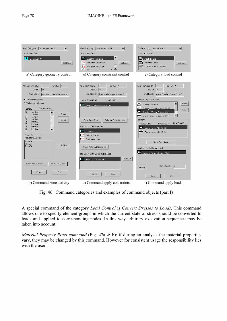
IMAGINE – an FE FrameworkPage 78
a) Category geometry control c) Category constraint control e) Category load control
b) Command zone activity d) Command apply constraints f) Command apply loads
Fig. 46 Command categories and examples of command objects (part I)
A special command of the category Load Control is Convert Stresses to Loads. This commandallows one to specify element groups in which the current state of stress should be converted toloads and applied to corresponding nodes. In this way arbitrary excavation sequences may betaken into account.
Material Property Reset command (Fig. 47a & b): if during an analysis the material propertiesvary, they may be changed by this command. However for consistent usage the responsibility lieswith the user.

User interface Page 79
a) Category material control c) Category computation control e) Category output control
b) Command material property d) Command elastic computing f) Command displacement output
Fig. 47 Command categories and examples of command objects (part II)
Elastic Computation command (Fig. 47c & d): the main aim of an analysis is to execute acomputation, even if it is considered here by just one out of many command objects. In the formthe currently active material laws and the corresponding zones are listed simply as a help for theuser. The laws themselves have been defined and assigned to the zones previously (c.f. Fig. 33).However, if several laws have been defined for a material, individual ones could be inactivatedhere.A special command of the category Computation is Computing Primary Stresses. This commandallows to assign a state of stress defined here in an analytical way to selectable element groups.
Displacement Output command (Fig. 47e & f): all commands of category Output Control serve todefine which field variables acting in which objects (e.g. Gauss points of elements) should beassembled and written to an external file.

IMAGINE – an FE FrameworkPage 80
As outlined in 3.8 "Postprocessing", this file may be interpreted by 3rd party software, which isresponsible for an adequate representation of the results.
It may be interesting to see, that as far as the implementation is concerned all command forms arederived from just one class called CFemTaskForm (Fig. 48), which is responsible for the wholewindows management. As outlined above, the task form is called when editing or creating a taskin the task manager. The individual command forms may then just concentrate on displaying thedomain of their limited concerns.
Fig. 48 Class hierarchy of command form classes
5.4.5 ConclusionsThe Fem Modeling Workbench is used to define all necessary resources at the project level. TheFem Task Workbench allows one to assign these resources to computational tasks and dispatchthem for execution.
The object centric paradigm of IMAGINE is also continued for the Analysis-Task-Commandobject model and its user interface the Fem Task Workbench. This architecture leads to a veryflexible analysis management. The user is practically free to define and assemble tasks. Thanks tothe favored non-anticipation of the OOP concept, he or she does not have to care, from asyntactical point of view, e.g. about the sequence in which individual commands may beassigned. Each command object is an independent entity which leaves the system behind in awell defined state. It should be noted that this does not liberate the user from planning the wholeanalysis carefully. The workbenches provide a powerful means for modeling and investigation,but they do not show what to investigate.
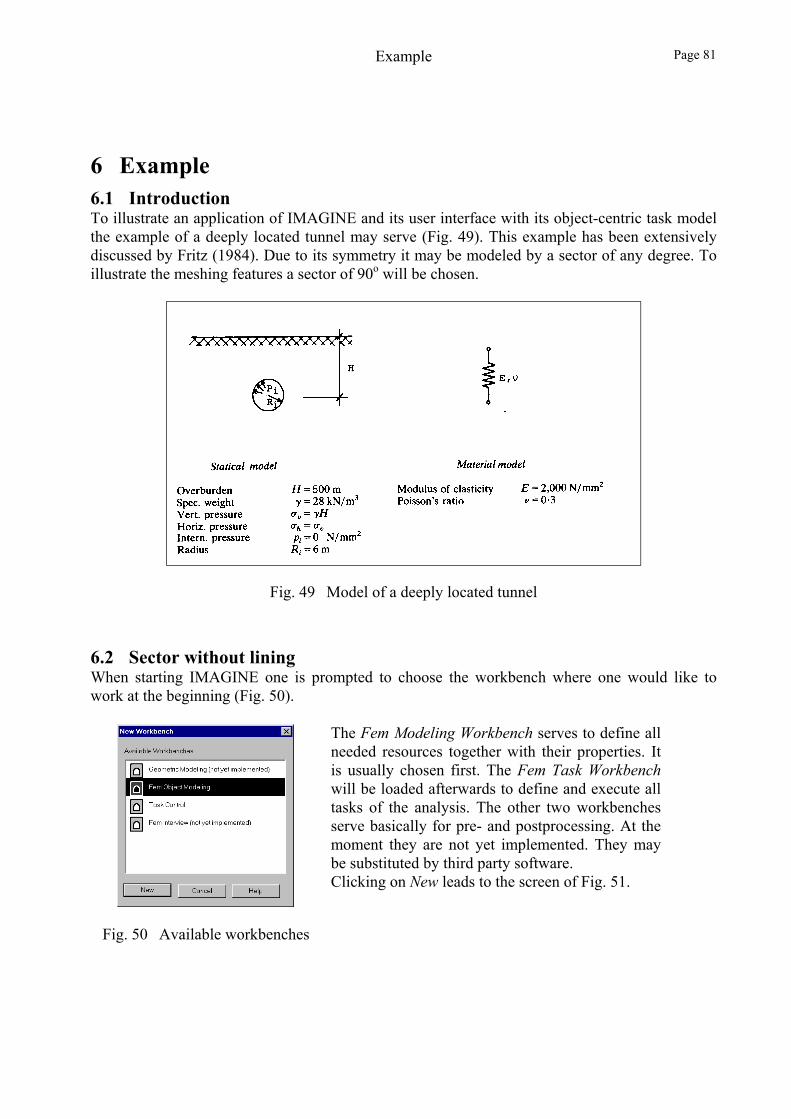
Example Page 81
6 Example6.1 IntroductionTo illustrate an application of IMAGINE and its user interface with its object-centric task modelthe example of a deeply located tunnel may serve (Fig. 49). This example has been extensivelydiscussed by Fritz (1984). Due to its symmetry it may be modeled by a sector of any degree. Toillustrate the meshing features a sector of 90o will be chosen.
Fig. 49 Model of a deeply located tunnel
6.2 Sector without liningWhen starting IMAGINE one is prompted to choose the workbench where one would like towork at the beginning (Fig. 50).
Fig. 50 Available workbenches
The Fem Modeling Workbench serves to define allneeded resources together with their properties. Itis usually chosen first. The Fem Task Workbenchwill be loaded afterwards to define and execute alltasks of the analysis. The other two workbenchesserve basically for pre- and postprocessing. At themoment they are not yet implemented. They maybe substituted by third party software.Clicking on New leads to the screen of Fig. 51.

IMAGINE – an FE FrameworkPage 82
Fig. 51 User Interface of IMAGINE
Two main windows may be recognized. The Info window in the background acts as a sort of logbook. The Fem Modeling window in the foreground represents the actual workbench. To be ableto work in it one has to import a geometric model (in the form of a solid model, not an FE mesh,c.f. 4.3.2 "Geometric modeling"). For this example the geometric model is very simple (Fig. 53).It has been prepared with the program FEMAP [http://www.entsoft.com/] and has been importedin the form of an ASCII file (Fig. 52), with menu option File / Import Geometry File.
The structuring of the input data is very simple andlucid. The first line is a code which is 0 if thegeometry is defined as a solid model, or 1 if it isdefined with superelements. The next line lists thenumber of vertices, followed by their coordinates.Then 1 surface is defined which is described by 11edges, followed by a reserved code 0 and thetopology of the edges, i.e. the numbers of thevertices connecting the edges.The numbers of the vertices are defined accordingto their input sequence, starting with 0.
Fig. 52 Input data of solid model
The resulting geometry is displayed in the workbench of Fig. 53: a rectangle of 70 m length, withthe excavation center at its lower left corner

Example Page 83
Fig. 53 Fem Modeling Workbench
Three principal frames may be distinguished: the frame on the right is used as an editor in whichforms are displayed which may be filled out to specify required data. In the middle the geometryis displayed together with varying graphical information, e.g. the mesh, vectors indicating forces,icons for supports etc. The frame on the left contains the toolboxes which facilitate a workingprocedure which is in agreement with the object-oriented paradigm. With the drop down boxObject Type at the top one specifies the object's type, e.g. a vertex, a curve or a surface.According to this type the toolbox Select Tool allows one to define how the objects should beselected (with the mouse in the middle frame), e.g. with a rubberband rectangle. In the Commandbox the commands or actions may be chosen which should be applied to the selected objects, e.g.apply a load.
Let's work through the example, how to assign the material properties to the geometric model. Todo this one specifies the type of object (Zone) in the Object Type box at the top (Fig. 54). Thenone chooses the selection tool Rectangle, and with the mouse a box is drawn around the wholemodel. The vertices which define the selected zone are marked with empty dots. Because thegeometric model consists of just one surface, this surface is regarded as the only zone available.Now the command is specified which should be applied to this zone. Four icons symbolize thepossible commands:
assign a material to the zone,
apply a distributed load,
define a node group which comprises the nodes of the selected zone,
define an element group which comprises the elements of the selected zone,
define a list of the selected zones.
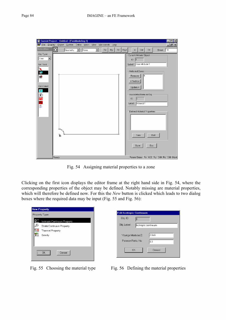
IMAGINE – an FE FrameworkPage 84
Fig. 54 Assigning material properties to a zone
Clicking on the first icon displays the editor frame at the right hand side in Fig. 54, where thecorresponding properties of the object may be defined. Notably missing are material properties,which will therefore be defined now. For this the New button is clicked which leads to two dialogboxes where the required data may be input (Fig. 55 and Fig. 56):
Fig. 55 Choosing the material type Fig. 56 Defining the material properties

Example Page 85
For inspecting the results at the end of the computation, data are often needed in some or allelements and nodes. Therefore already here both an element group and a node group are definedwhich comprise all items. To do this for the same object type Zone the corresponding commandsare executed. After saving these objects, in a similar way the support conditions and the forces atthe excavation boundary are defined. For this the object type Curve is chosen, the correspondingcurves are selected and the commands are applied.Up till now all commands have been applied to geometric objects at the level of the solid model,i.e. independently of the FE mesh. The last step before proceeding to the Fem Task Workbench,where the analysis is defined, is to define the mesh. This may be done via the menu option Mesh /Generate, leading immediately to the mesh of Fig. 57. This mesh has automatically beengenerated with the algorithm mentioned in 4.3.2 Geometric modeling. Further discussion of thisalgorithm follows in the next section. The mesh could easily be refined by clicking thecorresponding command icon, but for the sake of simplicity in this example it is accepted asdisplayed below.
Fig. 57 Automatically generated coarse mesh
At this point the physical model has been completely defined. What is missing is the definition ofthe analysis, or more specifically its individual tasks. For this one opens a task workbench via themenu options Workbench / New / Task Control and the corresponding editor in the right framevia Task / Taskmanager. There a new analysis and a first task is defined.
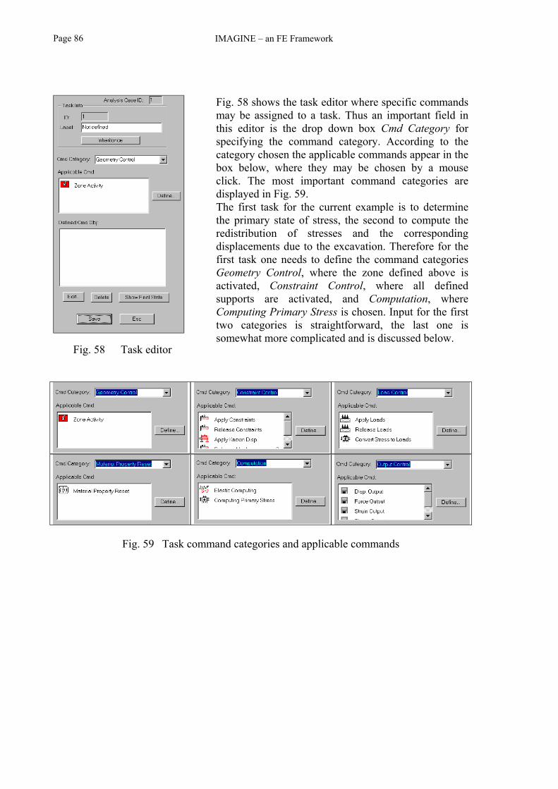
IMAGINE – an FE FrameworkPage 86
Fig. 58 Task editor
Fig. 58 shows the task editor where specific commandsmay be assigned to a task. Thus an important field inthis editor is the drop down box Cmd Category forspecifying the command category. According to thecategory chosen the applicable commands appear in thebox below, where they may be chosen by a mouseclick. The most important command categories aredisplayed in Fig. 59.The first task for the current example is to determinethe primary state of stress, the second to compute theredistribution of stresses and the correspondingdisplacements due to the excavation. Therefore for thefirst task one needs to define the command categoriesGeometry Control, where the zone defined above isactivated, Constraint Control, where all definedsupports are activated, and Computation, whereComputing Primary Stress is chosen. Input for the firsttwo categories is straightforward, the last one issomewhat more complicated and is discussed below.
Fig. 59 Task command categories and applicable commands

Example Page 87
Fig. 60 shows the editor where the task ComputingPrimary Stress may be defined. First one needs tospecify for which elements this task holds. For thisexample one chooses the Group of all Elements definedabove. In the box below the parameters are definedwhich characterize the primary state of stress. InGeotechnics it is well known that the primary state ofstress depends on many uncontrollable influences,which are usually not known by the engineer.Therefore IMAGINE provides the possibility to defineit with a few but important parameters: the overburden,the specific weight, and the coefficient of lateralpressure. The data analytically calculated based onthese parameters are then assigned to the finiteelements, without actually executing an FEcomputation.
Fig. 60 Computing primary stresses
For the remaining second task one defines the command categories Load Control, where theforces due to excavation at the excavation boundary are activated, once again Computation, butthis time specifying an elastic computation, and Output Control. For the latter displacements inall nodes and stresses in all elements are requested.
The actual analysis may be run interactively by clicking the corresponding option in the mainanalysis frame. In the process window (right frame in Fig. 61) all defined commands are listed forall tasks which form the current analysis. They may all be executed together or up to a so-calledbreak point which may be set by the user.
During the computation some log information is written to the Info Window. All results requestedunder Output Control are automatically written to a file. As outlined above the graphic facilitiesto display the results have not yet been implemented in IMAGINE. Therefore for this exampleIMAGINE has been configured to display the results in Tecplot [http://www.amtec.com/]. Justclicking the menu option Postprocessing (c.f. Fig. 61) first calls a special conversion programwhich assembles the data of IMAGINE's results file and converts it to a format supported byTecplot, and then loads Tecplot (Fig. 62).
When popping up Tecplot automatically displays the mesh of the current example (Fig. 62a).With just a few mouse clicks one can display contour lines (Fig. 62b) or vector diagrams. Anadditional valuable feature of Tecplot is the possibility to extract values along an arbitrarypolygon, e.g. along the x-axis, and to display these values in a new diagram.

IMAGINE – an FE FrameworkPage 88
Fig. 61 Process window and postprocessing menu
a) mesh b) contour lines
Fig. 62 Tecplot postprocessor

Example Page 89
6.3 Solid model versus superelementsThe example outlined above demonstrated the power of the automatic meshing algorithm ofIMAGINE. Unfortunately it does not always lead to satisfactory results. For illustration purposesthe same geometric model as above is used, but with the addition of a lining of 30 cm thickness.In Fig. 63 the mesh has been automatically generated with default parameters, i.e. without anyspecial measures for improving its quality. On the left side the mesh without a lining is displayed,the geometry on the right side includes a lining. The individual rows show the meshes at variousdegrees of zooming. One recognizes that the mesh in the vicinity of the excavation surfacebecomes irregular, especially for case b) with a lining.
a) without lining b) with lining
Fig. 63 Coarse FE mesh created from a solid model
Fig. 64 shows a similar picture but for a refined mesh. Refinement was executed by selecting theinitial mesh and clicking Refine. It may be recognized that for this case the irregularities in thevicinity of the excavation surface become even more pronounced. The reason is that the meshgenerator starts to mesh the lining at the crown with a reasonable subdivision. For the sake ofnumerical accuracy it subdivides the area using triangles and quadrilaterals, the latter having noobtuse angles. As the lining curves downwards smaller and smaller elements are generated.

IMAGINE – an FE FrameworkPage 90
a) without lining b) with lining
Fig. 64 Refined FE mesh created from a solid model
This phenomenon could be avoided by first generating the mesh for the lining semi-automaticallywith a regular subdivision, and then automatically for the rest of the geometry. However, acorresponding algorithm is quite demanding and at the moment not implemented.IMAGINE solves the problem in another way, though with some loss of generality andautomation. Instead of specifying the geometry with a general solid model, a 2D area may besubdivided into a number of quadrilaterals, so called superelements. The geometric model at thetop of Fig. 65 has been subdivided into seven areas or superelements for the lining, and sevensuperelements for the rest of the profile. Some third party software such as FEMAP supports thedefinition of superelements. During the meshing procedure IMAGINE subdivides opposite edgesof a superelement into a selectable number of stretches. To guarantee compatibility suchsubdivisions are propagated to neighboring elements.Part a) of Fig. 65 shows the resulting mesh having accepted all default parameters. For part b)one superelement of the lining and one of the rest have been assigned a refined subdivision. Forthe latter, additionally, an exponential subdivision has been specified. In this way a satisfactorymesh may be created.

Example Page 91
It may be seen that the meshes based on superelements are much better balanced than theircounterparts of Fig. 64 based on solid models.
a) Coarse mesh b) Refined mesh
Fig. 65 FE mesh created with superelements

IMAGINE – an FE FrameworkPage 92

Conclusions Page 93
7 ConclusionsThe object-oriented Finite Element framework IMAGINE has been presented which may be usedas a robust foundation for building applications in the field of geotechnical engineering. It wasshown that the decision to concentrate on geotechnical engineering was correct. Otherframeworks stemming from academic or informatics sources usually foresee extendibility todifferent types of finite elements, or to improved solution procedures. Opposed to that,IMAGINE aims to be extendable in terms of material models, types of physical variables andmanagement of computational tasks.The object-oriented approach simplifies the task of creating a flexible, extendable and easy-to-maintain program system. However, it is very important to have a well-structured and clearlylayered design to exploit it to the full.
Furthermore, it was recognized that there is a great difference between developing a frameworkjust as a proof of the applicability of a specific concept, and providing a framework which shouldbe usable and extendable for engineering practice and for research work. The main aim of theIMAGINE project was to provide a framework in the sense of a numerical infrastructure, onwhich developers can build to integrate required extensions with a minimum of development timeand side effects. This aim of the framework has certainly been fulfilled. It is now ready todevelop applications upon it.
However, in agreement with the quotation in the Introduction ("... now we have giganticcomputers, programming has become an equally gigantic problem.") the demands on the styleand the comfort of a program have increased so much, that building such applications is still aconsiderable work, even with the underlying aid of a framework. Up till now 6½ man years havebeen invested in the project of IMAGINE. Before a new programmer could efficiently start towork with it he or she would need to study C++ and IMAGINE itself, which would consumebetween a couple of months up to one year. Integration of new elements, e.g. beams forsimulating a lining, would require additional time. This time is necessary not so much forintegrating the element itself, but to adapt the corresponding routines for the automatic meshing(c.f. 4.3.2 "Geometric modeling"). Another important task consists in integrating more complexmaterial laws than just the elastic one currently defined.Thus let us continue as the slightly adapted saying is: Master, the work is finished, when should Istart to extend it ?

IMAGINE – an FE FrameworkPage 94

Appendix Page 95
Appendix 1: From procedural to object-orientedprogrammingFrom the beginning of software engineering, the constructive design of the programminglanguage played a central role in improving the ratio between benefit and expenditure. Thefollowing summary provides a condensed version of the evolution from procedural to object-oriented programming, thereby enabling an insight into the fundamental principles of OOP. Thisevolution may be split into five significant steps (Marti, 1988): Subprograms, Functions, Modules, Abstract Data Types, Object-oriented Programming.
The idea of subprograms, as used in the form of Macros in Assembler or GOSUB in Basic, wasto prevent duplication of code, and not to increase the level of abstraction. They were notfunctional entities. Because no parameters could be used, control had to be exerted by externalvariables.
Functions, e.g. called FUNCTIONs and SUBROUTINEs in FORTRAN, represent functionalentities and support parameters for input and output. However, they are still embedded in theglobal data space (e.g. through COMMONs), and therefore they are error prone to side effects.Their design is based on stepwise refinement (Wirth, 1971), executed in a sequential manner,which is called top-down design.
Modules, as promoted by Modula (Wirth, 1982), introduce information hiding by division in apublic interface, containing all external relations, and a hidden implementation part. Modulesmay contain several functions, i.e. they represent abstract data types with respect to functions.Because Modules are static entities which may not be individually derived for different objects,their data correspond to the sum of all objects, i.e. modules are not abstract data types withrespect to data.To improve reusability it is tried to form families of modules covering a specific task, whichmeans that top-down design is mixed up with bottom-up design.
Abstract Data Types, as introduced by Simula (Dahl and Nygaard, 1966) and used by C++(Stroustroup, 1998), contain data and the associated functions. The technique for this relies onclasses, analogously to modules, but which can be instantiated for each object separately. In C++,even operators may be defined as abstract data types (so-called operator overloading). Whichclass is effectively called is decided by the compiler depending on the types of operatorsinvolved. This characteristic is referred to as compile time polymorphism, or early binding.A limitation of abstract data types is that they are defined independently. If they should be reusedor extended, their source is copied and adapted. If one of such similar types is changed, all othersmust also be updated.
Object-oriented Programming overcomes the above mentioned limitation by supportinghierarchical structuring of abstract data types. This is achieved by inheritance and aggregation.

IMAGINE – an FE FrameworkPage 96
With the concept of inheritance specializations of a class may be added by deriving subclasseswhere only the differences must be defined. Derived classes inherit the non-private behavior(member functions) and context (member data) of their base classes. In a similar way aggregationembeds objects or references to objects into a container object. Derivation typically implies a top-down design (passing from the generality to the specialization), aggregation a bottom-up design(passing from simple classes to complex ones).Objects communicate with each other by calling their member functions, or expressed in OOPwords, by sending messages. If a derived class may not satisfy a message it is passed to its baseclass. If a pointer of one class points to another (derived-) class, the programming languageprovides mechanisms to define whether a message should be transferred to the base class or thederived class (see below). In this way extendable class hierarchies of logically or technicallysimilar entities may be built.
Because a derived class is more specialized than its base class, all member functions of the baseclass may also be used for an object of the derived class. This implies that a pointer of a baseclass may always be assigned an object of a derived class (but not vice versa). In this case it mustbe defined which member function should be called if it is defined at various hierarchy levels. Asdefault, the class defined by the type of the pointer is activated. However, if a member function isdefined as virtual, the class is activated to which the pointer currently points. Because the lattermay only be decided at run time, this ability is called runtime polymorphism, or late binding.
Typical for OOP is that projects are not developed sequentially, starting from analysis overdesign and implementation to testing, but rather iteratively or recursively, i.e. iteratively inparallel over all stages. This means that design and implementation should not be treatedseparately anymore.In the life cycle of a project often a broader applicability of a solution is discovered. I.e. usefulabstractions are more discovered than invented. The procedure is again a combination betweentop-down (decomposition) and bottom-up (assembling existing classes).
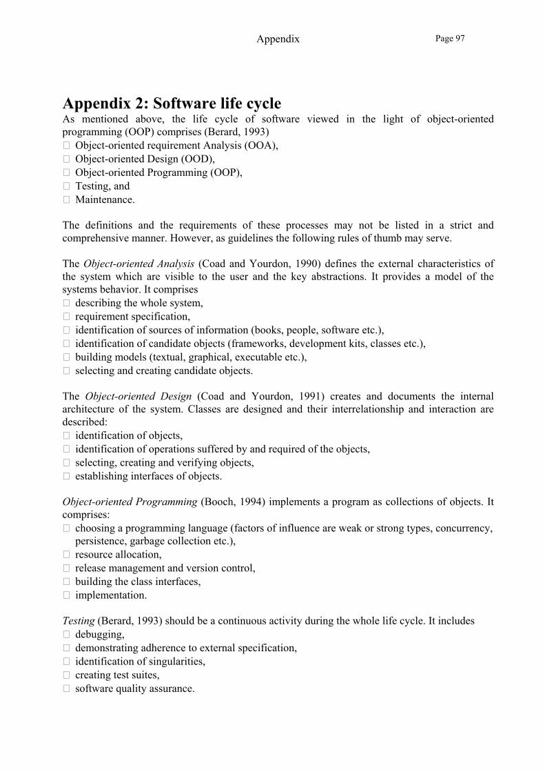
Appendix Page 97
Appendix 2: Software life cycleAs mentioned above, the life cycle of software viewed in the light of object-orientedprogramming (OOP) comprises (Berard, 1993) Object-oriented requirement Analysis (OOA), Object-oriented Design (OOD), Object-oriented Programming (OOP), Testing, and Maintenance.
The definitions and the requirements of these processes may not be listed in a strict andcomprehensive manner. However, as guidelines the following rules of thumb may serve.
The Object-oriented Analysis (Coad and Yourdon, 1990) defines the external characteristics ofthe system which are visible to the user and the key abstractions. It provides a model of thesystems behavior. It comprises describing the whole system, requirement specification, identification of sources of information (books, people, software etc.), identification of candidate objects (frameworks, development kits, classes etc.), building models (textual, graphical, executable etc.), selecting and creating candidate objects.
The Object-oriented Design (Coad and Yourdon, 1991) creates and documents the internalarchitecture of the system. Classes are designed and their interrelationship and interaction aredescribed: identification of objects, identification of operations suffered by and required of the objects, selecting, creating and verifying objects, establishing interfaces of objects.
Object-oriented Programming (Booch, 1994) implements a program as collections of objects. Itcomprises: choosing a programming language (factors of influence are weak or strong types, concurrency,
persistence, garbage collection etc.), resource allocation, release management and version control, building the class interfaces, implementation.
Testing (Berard, 1993) should be a continuous activity during the whole life cycle. It includes debugging, demonstrating adherence to external specification, identification of singularities, creating test suites, software quality assurance.

IMAGINE – an FE FrameworkPage 98
Maintenance (Booch, 1994) is the activity of managing postdelivery evolution. Application of thesoftware by independent users, usually the ultimate goal of each project, may lead to feedbacknot only with regard to errors but also to improvements and extensions, i.e. to all preceding stepsof the whole life cycle, with diminishing probability of occurrence.

Appendix Page 99
Appendix 3: The Document-View Concept of the MFCThe Document-View Concept distinguishes between the data of an application, which resides in aclass CDocument, and the view of it, controlled by class CView. Additionally, it relies on theapplication object, and the frame window (c.f. Fig. 6).
CView is responsible not only for the actual display of the data, but also to take and forward alluser interactions which could change the display either directly or by changing the underlyingdata. CView is a child-window of a frame which is never displayed. It exactly fits in the mainframe window, it represents the working area of the frame window. If the size of the framewindow is changed, so is the size of the view window. However, the view of the data should notbe mixed up with their actual display. The display is delegated to CFrameWnd, which resides atthe same level in the class hierarchy as CView, i.e. both are derived from CWnd. If one wouldtry to write something directly to the frame window, it would not be displayed, because the framewindow is completely covered by the view window. However, CFrameWnd detects which viewis active and its size, and sends the view the corresponding message to update the display.The Document-View Concept is therefore just a higher level abstraction integrated in the MFC.Also when programming without the Document-View Concept all frames are usually derivedfrom CFrameWnd, and the application itself is derived from CWinApp.
The Document-View Concept facilitates program development because it includes many standardtasks of a program, e.g. standard dialog boxes when closing a project or when printing. A furtheradvantage is that it relieves the programmer from organizing the whole information flow betweenthe application object, the document and the view. This is especially true in the case ofIMAGINE which relies on the Multiple Document Interface (MDI), which allows displayingseveral views of a document.
Additionally, the class CDocTemplate provides templates for creating new documents andviews, e.g. for a sound application, or for a new Imagine project (via menu option File / New).CDocTemplate serves to enable instantiating documents and views whose type is determined atruntime.For instantiating objects, e.g. documents and views, whose type is determined at runtime, theMFC provides so-called runtime classes. Each class, which is derived from CObject, may fill insome member data of CRuntimeClass. A member function of CRuntimeClass then allowscreating objects whose class is determined at runtime only. The MFC provides two macros to fillin the necessary member data: DECLARE_DYNCREATE(CMyClass) must be inserted in theheader file, and IMPLEMENT_DYNCREATE(CMyClass, CBaseClass) in the correspondingsource file.

IMAGINE – an FE FrameworkPage 100

Appendix Page 101
Appendix 4: Style guideIntroductionA lucid programming style is an indispensable prerequisite for maintaining a large program.Yoon (1990) reports that almost 95% of all failed software projects of the U.S. GovernmentAccounting Office can be attributed to impossible maintenance and adaptation to newrequirements. Undisciplined programming style is very hard to prevent. However, it is hoped thatthe OOP paradigm leads also to an improved style, e.g. due to its inherent abstractionpossibilities.To improve the global overview it was aimed to document each file, class and member asoutlined below. To improve readability in the small mnemonic names for types and variables areused.
Online documentationThe professional software engineer acknowledges the importance of creating certaindocuments, but never does so (Booch, 1994).
Blocks of comments are inserted in a routine way at the following three places: at the beginning of each class, at the beginning of each method, at the beginning of each file.
At the beginning of each class the following template is introduced, filled out with the necessaryinformation:// ************************************************// class ClassName: - short description// Description:// Creation Parameters:// Destructor Behavior:// Methods: - prototype and short description// Parent Classes:// Child Classes:// Friend Classes:// ************************************************
It should be noticed that especially the information about the child classes may sometimes not becomplete, because subclasses may be derived without changing this information in the baseclass(intentionally or unintentionally).
Similarly at the beginning of each method the following template is introduced:// ************************************************// MethodName::ClassName: - short description// Description:// Parameters:// Class variables:// Methods: - prototype and short description// Files:// Returns:// ************************************************

IMAGINE – an FE FrameworkPage 102
Similarly at the beginning of each file the following template is introduced:// ************************************************// FileName: - short description of contents//// standard header files#include directives // e.g. <iostream.h> etc.// class declarations#include "appdefs.h" // forward declarations of all essentialclasses#include directives // forward declarations of local classes// function declarations#include directives // forward declarations of functions// basic definitions
// typedefs's, constants etc.// local header files#include directives //// ************************************************
Naming conventionsReadability in the small is achieved by adhering to some naming conventions, especially the so-called Hungarian Notation (Simonyi and Heller (1991), for a summary see alsohttp://home.jtan.com/~gregleg/hungarian.html or http://support.microsoft.com/support/kb/articles/Q173/7/38.asp). This notation specifies the form of variable names in order to lead toinformation about their content. Specifically variable names should be prefixed with one or morelowercase characters to indicate their type, and the name itself should start with an uppercaseletter, e.g.
Prefix Meaning Explanationch char signed char, 8 bit intby BYTE unsigned char, 8 bit uintw WORD unsigned int, length machine or OS dependents short 16 bit intus unsigned short 16 bit uintn int length machine or OS dependentu unsigned int length machine or OS dependenti long 32 bit intui unsigned long 32 bit uintft float 32 bit floatdft double float 64 bit floatb BOOL unsigned char, 8 bit uintsz zero terminated strings stringC classp pointerr referencea actual valuec int or long counterf BOOL flagx,y,z float coordinatesd differencea array

Appendix Page 103
Examples for this notation areWORD wFileSize; // word, i.e. unsigned intchar * pszCmdLine; // pointer to a zero terminated string
Additionally, constants are specified by capital letters, perhaps separated by underscores, e.g.#define HKEY_CURRENT_USER 0x80000001
Standards for C++ are not yet common. However, one can extend the Hungarian Notation toinclude classes and members.
Classnames should start with a capital letter, prefixed by 'C' (Microsoft standard), e.g.class CElementOperationList;
Instances of classes, i.e. objects, should give a hint to the name of the class. This may beachieved in either of two ways: with prefixes, e.g.
CElementOperationList eolTriangles;
It may be mentioned that these prefixes cannot be unique, because they should be as short(about 3 characters) but also as informative as possible. Non-uniqueness does not matterbecause of the usually very limited scope of objects. They may be distinguished from prefixesof standard C-types by their length, and from member functions by not being verbs.
with meaningful object names, prepended by an "a", e.g.CElementOperationList aTriangleList;
Member functions should use verb/(attribute/)object notation, e.g.CEllipse createEllipticRegion();
where the verb is spelled in small letters. (Sometimes in C++ object/verb notation is used: e.g.WindowDestroy, however despite its more object-oriented approach its not widely used, perhapsbecause of its difficult readability.)It may be observed that with this definition, member functions give no indication of their returntype. The only exception is when the member function returns a reference to an object. If theobject was created with new inside the member function, this is perfectly legal, but the callermust be informed that he is responsible for deleting the object. As a hint an "R" in front of theobject is used:
CEllipse& createREllipticRegion();

IMAGINE – an FE FrameworkPage 104
References Page 105
References
Abdalia Jamal A., Yoon C. John (1992): Object-oriented finite element and graphics Data-translation facility. J. Computing in Civil Engineering, v. 6, no. 3.
Apple Computer (1986): MacApp Programmers Manual. Cupertino, California.AutoCAD user's guide (1995): AutoCAD release 13, user's guide. Autodesk Inc.Baugh John W., Rehak Daniel R. (1987): Object-oriented design of Finite Element programs.
Report Dept. Of Civil Engng., Carnegie-Mellon University, Pittsburg.Baugh John W., Rehak Daniel R. (1989): Computational Abstractions for Finite Element
Programming. Report 89-182. Dept. Of Civil Engng., Carnegie-Mellon University,Pittsburg.
Berard Edward V. (1993): Essays on object-oriented software engineering. Prentice Hall Inc.Boender Edwin; Bronsvoort Willem F.; Post, Frits H. (1994): Finite-element mesh generation
from constructive-solid-geometry models. Computer-Aided Design, v. 26, no. 5.Booch Grady (1994): Object-oriented analysis and design. Benjamin/Cummings.Bruaset Are Magnus, Langtangen Hans Petter (1996): Object-Oriented Design of Preconditioned
Iterative Methods in Diffpack[http://www.oslo.sintef.no/avd/33/3340/diffpack/dplibrary.html].
Buchanan Bruce G., Duda Richard O. (1983): Principles of Rule-Based Expert-Systems. Advancein Computers, v.22.
Coad Peter, Yourdon Edward (1990): Object-oriented analysis. Yourdon Press, Prentice Hall.Coad Peter, Yourdon Edward (1991): Object-oriented design. Yourdon Press, Prentice Hall.Crisfield M.A., 1986: Finite Elements and Solution Procedures for Structural Analysis. Pineridge
Press.Cullens Chane (1995): Serialization and MFC. Dr. Dobb's Journal, no. 229, April 1995.Dahl O-J., Nygaard K. (1966): SIMULA - an Algol based simulation language. Communications
of the ACM, v. 9, no. 9.Dijkstra Edsger (1972): The humble programmer. Communications of the ACM,v. 15, no. 10, Oct.Dubois-Pelerin Yves-Dominique (1992): Object-oriented finite elements: programming concepts
and implementation. Diss. no. 1026, Swiss Federal Institute of Technology Lausanne.Dwyer J.F. (1989): Functional programming for finite elements. Computers & Structures, v. 33,
no. 6.Fan Yung (1990): An integrated knowledge-based finite element analysis system. Diss. no.
9111471, Carnegie-Mellon University, Pittsburg.Felippa C.A., Stanley G.M. (1985): NICE: a utility architecture for computational mechanics.
Proc. Finite Element Methods for Nonlinear Problems, Trondheim, Springer Verlag.Fenves Gregory L. (1989): Object-oriented models for engineering data. Computing in civil
engineering, Atlanta.Forde B., Foschi R., Stiemer S. (1989): Object-Oriented Finite Element Analysis. Computers &
Structures, v. 34, no. 3.Fritz P. (1983): RHEO-STAUB User's Manual. Report Swiss Federal Institute of Technology,
Zürich [http://www.igt.ethz.ch/www/search/publication.asp?publication=1].

IMAGINE – an FE FrameworkPage 106
Fritz P. (1984): An Analytical Solution for Axisymmetric Tunnel Problems in Elasto-Viscoplastic Media. Int. J. Num. Analytical Meth. Geomech., v. 8[http://www.igt.ethz.ch/www/search/publication.asp?publication=18].
Gago J.P. De S.R., Kelly D.W., Zienkiewicz O. C., Babuska I. (1983): A posteriori error analysisand adaptive processes in the finite element method: Part II - adaptive mesh refinement.Int. J. Numerical Methods in Engineering, v. 19.
Gamma Erich, Helm Richard, Johnson Ralph, Vlissides John (2000): Design patterns : elementsof reusable object-oriented software. Addison-Wesley.
Goldberg A., Robson D. (1983): Smalltalk-80: the language and its implementation. Addison-Wesley.
Gorlen Keith E., Sanford M.Orlow, Perry S.Plexico (1990): Data abstraction and object-orientedprogramming in C++. Publ. John Wiley & Sons Ltd.
Groth Boris, Jähnichen Stefan, Koch Wilfried (1994): Prinzipien und Strukturen objekt-orientierter Systementwicklung. 17. Europäischer Congress für Technische Kommu-nikation, Hamburg, Feb.
Johnson Ralph E., Foote Brian (1988): Designing reusable classes. J. Object-OrientedProgramming, v. 1, no. 2.
Kela A., Perucchio R. (1988): Hierarchical incremental finite element analysis through solidmodeling, Proc. ASME Int. Computers in Engineering Conf., v.3.
Kelly D.W., Gago J.P. De S.R., Zienkiewicz O. C., Babuska I. (1983): A posteriori error analysisand adaptive processes in the finite element method: Part I - error analysis. Int. J.Numerical Methods in Engineering, v. 19.
Langtangen Hans Petter (1993): Diffpack: Software for Partial Differential Equations[http://www.oslo.sintef.no/avd/33/3340/diffpack/dplibrary.html].
Lippman Stanley B. (1998): C++ primer. Addison-Wesley.Mäntylä Martti (1988): An introduction to solid modeling. Computer Science Press, Rockville,
U.S.A.Marty Rudolf (1988): Von der Subroutinentechnik zu Klassenhierarchien. Report of the Institute
of Informatics, University of Zürich.Meyers Scott (1998): Effective C++. Addison-Wesley.Microsoft Visual C++ (1993): Microsoft Visual C++, Programmers Guides. Microsoft
Corporation.Miller Gregory R. (1988): A LISP-based object-oriented approach to structural analysis.
Engineering with Computers, v. 4, no. 1/2.Miller Gregory R. (1989): An object-oriented approach to structural analysis and design. Civil-
Comp Press, AI techn. and applications for civil and structural engineering, Sept. 1989.Mo O., Klem F., Pahle E., Harwiss T. (1978): Finite Element programs based on general
programming systems. Computers & Structures, v. 8, no. 6.Müller S., Kells K., Fichtner W. (1991): Automatic Rectangle-Based Adaptive Mesh Generation
without Obtuse Angles. Techn. Report no. 91/2 of the Integrated Systems Laboratory,Report Swiss Federal Institute of Technology, Zürich.
Oestereich Bernd (1998): Objektorientierte Softwareentwicklung mit der Unified ModelingLanguage. R. Oldenbourg Verlag.
POET (1993): POET, programmer's and reference manual. BKS Software GmbH, Hamburg,Germany.
Rehak Daniel R. (1986): Artificial Intelligence Based Techniques for Finite Element ProgramDevelopment. Reliability of methods for Engineering Analysis. Pineridge Press.

References Page 107
Rehak Daniel R., Baugh John W. (1988): Alternative programming techniques for finite elementprogram development. Report Dept. Of Civil Engngn., Carnegie-Mellon University,Pittsburg.
Riel, Arthur (1996): Object-Oriented Design Heuristics. Addison-Wesley.Simonyi, Charles and Heller, Martin (1991): The Hungarian Revolution, Byte, August, pp.131-
138.Sims John Michael (1994): An object-oriented development system for finite element analysis.
Dissertation no. 9424155 of the Arizona State University, U.S.A. Dissertation AbstractsInternational. Volume: 55-04, Section: B, page: 1564.
Smith I.M. (1994): The advantages of Fortran 90 in computational geomechanics. ComputerMethods and Advances in Geomechanics, Balkema.
Smith John Miles, Smith Diane C.P. (1977): Database abstractions: aggregation andgeneralization. ACM Transactions on Database Systems, v. 2, no. 2.
Stevens Al (1992): C++ database development. MIS:Press.Stevens Al (1995): Alexander Stepanov and STL. Dr. Dobb's Journal, March.Stroustroup Bjarne (1998): The C++ programming language. Addison-Wesley.UTRC (Underground Technology Research Council) (1991): Potential Topics for Research and
Development in Underground Engineering. Tunneling and Underground SpaceTechnology, v. 6, no. 3.
VISTA++ (1991): VISTA++, the object-oriented database management system for C++. RaimaCorp., Bellevue, WA, U.S.A.
Wirfs-Brock Rebecca, Wilkerson Brian, Wiener Lauren (1990): Designing object-orientedsoftware. Prentice Hall Inc.
Wirth Niklaus (1971): Program development by stepwise refinement. Communications of theACM, v. 14, no. 4.
Wirth Niklaus (1982): Programming in Modula-2. Springer Verlag.Yoon Chong-Yul (1990): Object-oriented paradigms for computer aided structural engineering.
Dissertation Abstracts International. Volume: 52-04, Section: B, page: 2199.Yu George Gang (1994): Object-oriented models for numerical and finite element analysis.
Dissertation no. 9421042 of the Ohio State University, U.S.A.Yu George, Adeli H. (1993): Object-oriented finite element analysis using EER model. J. of
Structural Engng., v. 119, no. 9.


![[USACE] Geotechnical Analysis by the Finite Element Method](https://img.pdfslide.us/doc/110x75/546a5959b4af9f752c8b468c/usace-geotechnical-analysis-by-the-finite-element-method.jpg)


![[FEM] Geotechnical Analysis by the Finite Element Method](https://img.pdfslide.us/doc/110x75/55cf9734550346d033903ce5/fem-geotechnical-analysis-by-the-finite-element-method.jpg)