Embed Size (px)
Citation preview
Authors:"~
watson, G.V.R. and carder, D.R.
COMPARISON OF THE MEASURED AND COMPUTEDPERFORMANCE OF A PROPPED BORED PILE RETAINING
WALL AT WALTHAMSTOW
Publication:-
PROC. INST. OF CIVIL ENGINEERS, GEOTECHNICALENG., 107, PP 127-133
Year of publication:-
1994
--
REPRODUCED WITH KIND PERMISSION FROM:-Thomas Telford Services Ltd
Thomas Telford House1 Heron Quay
London E144JD
Comparison of the measured andcomputed performance of abored pile retaining wall at
WalthamstowG. v. R. Watson and D. R. Carder
Proc lnslll Cio.Engrs Geotech.Engng. 1994. 107.July. 127-133
Gro.nd Boord
Geotechnicol EngineeringAdvisory PonelPoper 10447
Written discussioncloses 15 SePtember 1994
Geoff Wotson,Higher ScientificOfficer, Bridges &Ground
EngineeringResource Cenlre,
TronsportReseorch
Loborotory,Crowthorne
This Paper compares the results of field 3. In this Paper the site observations havemonitoring during the construction of a been compared with the results from finitebored pile retaining wall propped at car- element analyses.riageway level with the computed resultsfrom finite element analyses using the Basis of analysesMohr-Coulomb model. Field monitoring 4, The finite element analyses were per-was carried out to measure ground move- formed using the CRISP90 package (Britto andments, total lateral stresses and pore- Gunn).' The soil was modelled as an elasticwater pressures, together with wall perfectly plastic material with the yield surfacemovements and bending moments. Gener- being defined by the Mohr-Coulomb yield cri-ally, good correlation was obtained terionbetween the measured and computed 5. Initially, an axisymmetric analysis wasresults. carried out to simulate the installation of a
This analysis was performed as a back single pile by removing soil elements and 'repla-analysis but all the data used was avail- cing them with concrete elements at the axis ofable prior to construction and could there- totation, As pile installation on site tdok placefore have been used in a class A very quickly over a period of a few hours,prediction. undrained conditions were assumed for this
analysis.6, A more detailed mesh was constructed to
Introduction accommodate the different soil strata and alsoMany deep excavations for road improvement to enable the underpass construction sequenceschemes in urban areas are currently being con- to be modelled by removal of elements. Thisstructed using bored pile and diaphragm analysis was carried out under plane strainretaining walls, This is particularly so in the conditions with the wall being' wished in-London area, where site access and availability place' and a coupled consolidation analysisof land make other engineering solutions less performed to model the long term condition.viable. The structural loading on walls andmovements in the nearby ground will depend Material propertiesupon the stiffness of, the wall, the type of Soil parameterssupport system, the InItIal stress stat~ m the, 7, The soil properties used in the analysesground and th~ str~ss changes occurring dun~g came from several sources, the original siteeach constructIon stage (see Pot;s and Foune investigations carried out in August 1983 andand Hlggms, Potts,and Symons ), , January 1988 together with TRL in-situ testing
2. ComprehensIve InstrumentatIon was carried out in May 1992 at an adjacent' greenI~stalled at Walthamstow on \he,A406.,North field' site, The rest of the material propertiesCIrcular Road m London, to mom tor soll- d f e I'
OUS analyses In London, d h ' f were rawn rom pr vstruct~re.mteractlon unng t e const~uctlon 0 Clay (see Burland and Kalra' and Carswell,a contiguous bored pIle wall founded m London C d d S ns.)CI A h ' f fh areran ymo .
ay t t IS sIte, excavation m ront 0 t e 8, The soil strata profile was developedwalls took place beneath temporary props from the 1983 site investigation, This gave bestwhIch spanned the underpass wIth the 11m shed fit strength parameters of c' = 20 kNm -2 andstructure beIng permanently propped below the -I.' =22' for theLondonClay and these valuesh d d h '" , Derek CardercarrIageway usmga lOge eslgn at t e were used for the Mohr.Coulomb analyses, Fol. Principal Sci~nti-
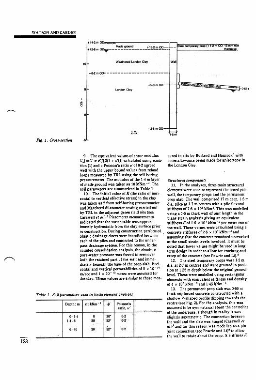
prop-wall connection, At the mstrumen:ed lowing the upper bound recommended by fic Officer,section, the wall was formed from 17 m ong. Burland and Kalra.' the clay modulus was Bridges & Ground1,5 m d,a, pIles at 17 m centres wIth a retaIned varied with depth using Engineering Reheight of 8 m Other dimensions are shown in source Centre,Fig 1 The results and interpretation of the site E' = 32 + 84z (I) Transport Re-
data are reported by Carswell, Carder and where E' is the drained elastic modulus in search LaborGent 3 MNm ~ 2 and z is the depth in metres atory, Crowthornt
1?7
WATSON AND CARDER
eC0
,
Fig. 1. Cross-section
9. The equivalent values of shear modulus sured in ~itu by Burland and Hanc?ck' withG.{ =G' = E'1[2(1 + v')]} calculated using equa- some allowance being made for anIsotropy Intion (I) and a Poisson's ratio v' of 0.2 agreed the London Clay.well with the upper bound values from reloadloops measured by TRL using the self-boringpressuremeter. The modulus of the 1.4 m layer Structural componentsof made ground was taken as 10 MNm -2. The II. In the analyses, three main structuralsoil parameters are summarized in Table I. elements were used to represent the bored pile
10. The initial value of K (the ratio of hori- wall, the temporary props and the permanentzontal to vertical effective stress) in the clay prop slab. The wall comprised 17 m deep, 15 mwas taken as 2 from self.boring pressuremeter dia. piles at 1.7 m centres with a pile flexuraland Marchetti dilatometer testing carried out stiffness of 7.6 x 10" kNm2. This was modelledby TRL in the adjacent green field site (see using a 1.5 m thick wall of unit length in theCarswell et al.).' Piezometer measurements plane strain analysis giving an equivalentindicated that the water-table was approx- stiffness E of 1.6 x 10' kNm -2 per metre run ofimately hydrostatic from the clay surface prior the wall. These values were calculated using ato construction. During construction perforated, concrete stiffness of 26 x 10' kNm - 2 and
plastic drainage ducts were installed between assuming that the concrete remained uncrackedeach of the piles and connected to the under. at the small strain levels involved. It must bepass drainage system. For this reason, in the noted that lower values might be used in longcoupled consolidation analysis, the absolute term design in order to allow for cracking andpore-water pressure was forced to zero over creep of the concrete (see Powrie and Li)."both the retained part of the wall and imme- 12. The steel temporary props were 1.2 mdiately beneath the base of the prop slab. Hori- dia. at 27 m centres and were grouted in posi-zontal and vertical permeabilities of 5 x 10⁻¹⁰ tion at 1.25 m depth below the original groundmlsec and I x 10-10 mlsec were assumed for level. These were modelled using rectangularthe clay. These values are similar to those mea- elements with equivalent stiffness and density
of4 x 10'kNm-2and 1.45kNm-'.13 The permanent prop slab was 065 m
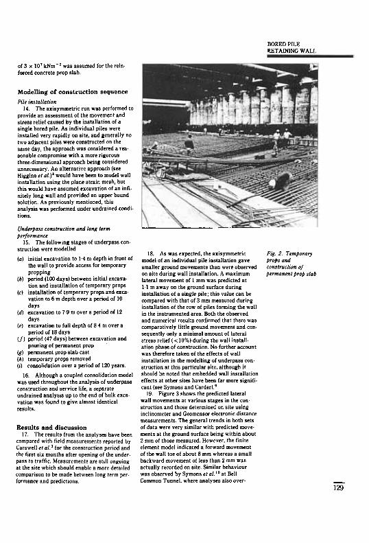
Tallie 1. Soil parameters used infinite element analyses thick reinforced concrete constructed with ashallow Y-shaped profile dIpping towards the
Bulk centre (see Fig. 2). For the analysis, this wasdensity: kNm' assumed to be symmetrical about the centreltne
of the underpass, although in reality it wasslightly asymmetric. The connection betweenthe wall and the slab was hinged (Carswell 1'/al.)' and for this reason was modelled as a pinjoint connection (see Powrie and Li)" tn allowthe wail to rotate about the prop A stiffness f:
~
Soil type
1819-1
19-9
Made groundWeathered
London ClayUnweathered
London Clay
128
BORED PILERETAINING WALl.
of 3 X 10' kNm - 2 was assumed for the rein.
forced concrete prop slab.
Modelling of construction sequence
Pile instal/ation14. The axisymmetric run was performed to
provide an assessment of the movement andstress relief caused by the installation of asingle bored pile. As individual piles wereinstalled very rapidly on site, and generally notwo adjacent piles were constructed on thesame day, the approach was considered a rea.sonable compromise with a more rigorousthree-dimensional approach being consideredunnecessary. An alternative approach (seeHiggins et al.)' would have been to model wallinstallation using the plane strain mesh, butthis would have assumed excavation of an infi-nitely long wall and provided an upper boundsolution. As previously mentioned, thisanalysis was performed under undrained condi-tions.
Underpass construction and long term
performance15. The following stages of underpass con-
struction were modelled
(a) initial excavation to 1.4 m depth in front ofthe wall to provide access for temporarypropping
(b) period (100 days) between initial excaya-tion and installation of temporary props
(c) installation of temporary props and exca-vation to 6 m depth over a period of 10days
(d) excavation to 7.9 m over a period of 12
days(e) excavation to full depth of 8.4 m over a
period of 18 days(f) period (47 days) between excavation and
pouring of permanent propig) permanent prop slab cast(h) temporary props removed(i) consolidation over a period of 120 years.
16. Although a coupled consolidation modelwas used throughout the analysis of underpassconstruction and service life, a separateundrained analysis up to the end of bulk excavation was found to give almost identicalresults.
Results and discussion17. The results from the analyses have been
compared with field measurements reported byCarswell et al.' for the construction period andthe first six months after opening of the under-pass to traffic. Measurements are still ongoingat the site which should enable a more detailedcomparison to be made between long term per.formance and predictions
Fig. 2. Temporaryprops andconstruction ofpermanent prop slab
129
18. As was expected, the axisymmetricmodel of an individual pile installation gavesmaller ground movements than were observedon site during wall installation. A maximumlateral movement of 1 mm was predicted at[.l maway on the ground surface duringinstallation of a single pile; this value can becompared with that of 3 mm measured duringinstallation of the row of piles forming the wallin the instrumented area, Both the observedand numerical results confirmed that there wascomparatively little ground movement and con.sequently only a minimal amount of lateralstress relief « 10%) during the wall install.ation phase of construction. No further accountwas therefore taken of the effects of wallinstallation in the modelling of underpass con.struction at this particular site, although itshould be noted that embedded wall installationeffects at other sites have been far more signifi.cant (see Symons and Carder),'
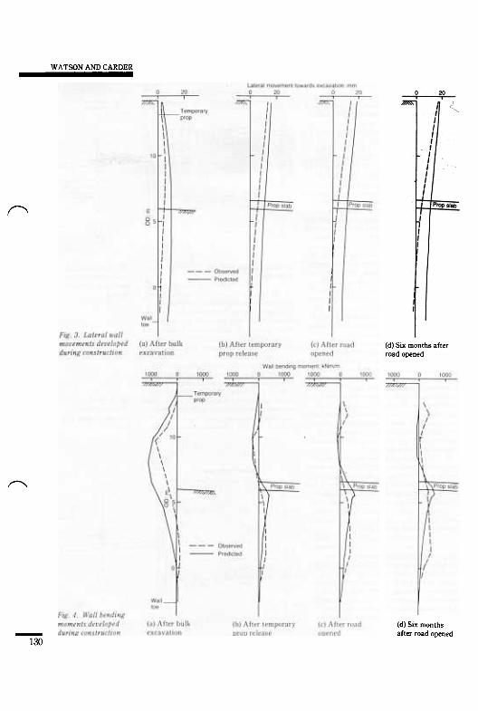
19. Figure 3 shows the predicted lateralwall movements at various stages in the con.struction and those determined on site usinginclinometer and Geomensor electronic distancemeasurements, The general trends in both setsof data were very similar with predicted move.ments at the ground surface being within about2 mm of those measured, However, the finiteelement model indicated a forward movementof the wall toe of about 8 mm whereas a smallbackward movement of less than 2 mm wasactually recorded on site. Similar behaviourwas observed by Symons ef a/lo at BellCommon Tunnel, where analyses also over.
WATSON AND CARDER
("I
(d) Six months afterroad opened
~
(d) Six monthsafter road opened-
130
BORED PILERETAINING WALL
Late,e' wallmovament
mm
~
/1
D;slance beh;nd wall m
',5,,~,", ,~"" ~ ~ -"
~- ObseNed- P'edicled'~m, , -
... --~ l"-
~~ ~~t;;-11- ,,",,'ontal
moosmenl nol
, measu,ed on, .,ca,.ted .0.~ I
0;;' ~I...
... ."
predicted movements of the toe of the secantpile retaining walls.
20. The predicted bending moments in thewall are compared with those determined usingvibrating wire strain gauges mounted on thesteel reinforcing cage in pairs at the front andback. In evaluating moment, bending strain £-was first calculated at each depth from t(£,- £,), where £, and £, are the strains on the
front and back of the wall. Bending moment is Ethen given by Ef(d'y/dx'j, ie. Ef£_/c where c is 8equal to the pile radius. The comparison ofthese results is shown in Fig. 4. Immediatelyafter excavation to formation level, the analysisgave a peak bending moment of 1100 kNm per'metre run of wall compared with a measuredmoment of 850 kNm. However, the analysis pre-dicted the peak at 6 m below ground lev~l while -L" - - ..the field measurements indicated a maxImum at -. .' ..about 4.5 m below ground level. The predictedtemporary prop load at this stage was 455 kNper metre run of wall and this can be compared at shallow depths below the permanent Fig. 5. Ground andwith measured values varying between 200 kN prop slab. wall movements sixand 480 kN depending on temperature. The 24. The finite element stresses, calculated months after roadthermal expansion effects with steel props of for 120 years after construction, are compared openedthis type are well known and as such the props with values typically used in design in Fig. 8.provide proactive support (see Ferniej.'1 The Close to the wall on the retained side, the totalpredicted and measured bending moment pro- lateral stresses were compared with those cor-files shown in Fig. 4 remained broadly similar responding to a K value of unity. Although K isat later stages of construction. an effective stress ratio, when its value is unity
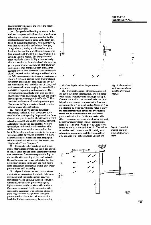
21. Figure 5 shows ground movement the tota!lateral stress equals the overburdenvectors and horizontal wall movement at six stress and is independent of the pore-watermonths after road opening- 1~ general, the fin!te pressure distribution. On the excavated side,element analysIs tended to slIghtly over-predict effective stresses were calculated using the bestlateral movement and under-predict settlement. fit soil parameters from triaxial compressionLateral movement was particularly well pre- tests of c' = 20 kNm -, and ,p' = 22". and lowerdicted close to the wall on the retained side, bound values of c' = 0 and ,p' = 22°. The values Fig. 6. Predictedwhile some overestimation occurred further of passive earth pressure coefficient Kp were ground and wallback. Reduced ground movements further away determined assuming a wall friction angle of movements after,would probably have been predicteli if a more ,p' /2 and zero wall cohesion from Caquot and yearssophisticated soil model had been employedwith increased soil stiffness at low strain (seeHiggins et ai-' and Simpson ").
22. The predicted ground and wall move- ...ments after approximately 120 years are shown , ,in Fig. 6. Little change in the lateral mQvements -~was determined from those reported in Fig. 5 atsix months after opening of the road to traffic.Generally, more heave was calculated for thisperiod particularly in front of the wall wheresome dIssipation of negative excess pore-waterpressure was still occurring.
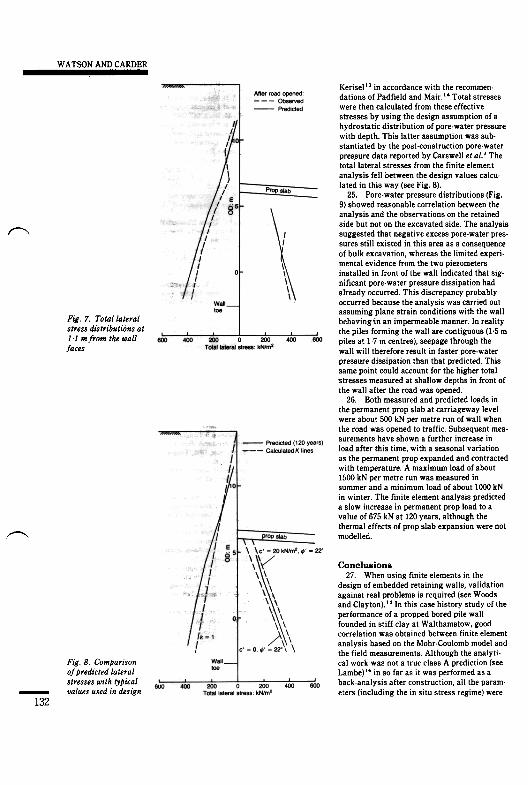
23 Figure 7 shows the total lateral stressdistributions determined from both field mea-surements and the finite element analysisimmediately after opening the road to traffic.Generally. the analysis predicted slightlyhigher stresses on the retained side at depththan were measured. On the excavated sidereasonable agreement was obtained althoughthere was some indication from the spadepressure cell at about 3 m below formationlevel that higher stresses may be developing
Lata,al war-ovemant
mmDlstanca beh,nd wall m J 2(110 5 0 ~
'-' '-"'-"III
r""11 L~~ :..-..-r'
e
~~ -
,~
-111
WATSON AND CARDER
~
Fig. 7. Totollateralstress distributions at1.1 mfrom the wallfaces
Kerisel" in accordance with the recommen.dations of Padfield and Mair.I' Total stresseswere then calculated from these effectivestresses by using the design assumption of ahydrostatic distribution of pore.water pressurewith depth. This latter assumption was sub-stantiated by the post-construction pore.waterpres~ure data reported by Carswell et al.' Thetotal lateral stresses from the finite elementanalysis fell between the design values calcu-lated in this way (see Fig. 8).
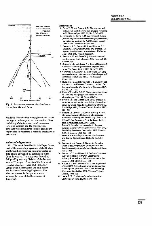
25. Pore.water pressure distributions (Fig.9) showed reasonable correlation between theanalysis and the observations on the retainedside but not on the excavated side. The analysissuggested that negative excess pore-water pres-sures still existed in this area as a consequenceof bulk excavation, whereas the limited experi-mental evidence from the two piezometersinstalled in front of the wall indicated that sig-nificant pore-water pressure dissipation hadalready occurred. This discrepancy probablyoccurred because the analysis was carried outassuming plane strain conditions with the wallbehaving'in an impermeable manner. In realitythe piles forming the wall are contiguous (1.5 mpiles at 1.7 m centres), seepage through thewall will therefore result in faster pore-waterpressure dissipation than that predicted. Thissame point could account for the higher totalstresses measured at shallow depths in front ofthe wall after the road was opened.
26. Both measured and predicted loads inthe permanent prop slab at carriageway levelwere about 500 kN per metre run of wall whenthe road was opened to traffic. Subsequent mea-surements have shown a further increase inload after this time, with a seasonal variationas the permanent prop expanded and contractedwith temperature. A maximum load of about1500 kN per metre run was measured insummer and a minimum load of about 1000 kNin winter. The finite element analysis predicteda slow increase in permanent prop load to avalue of 675 kN at 120 years, although thethermal effects of prop slab expansion were notmodelled.~
Conclusions27. When using finite elements in the
design of embedded retaining walls, validationagainst real problems is required (see Woodsand Clayton)." In this case history study of theperformance of a propped bored pile wallfounded in stiff clay at Walthamstow, goodcorrelation was obtained between finite elementanalysis based on the Mohr-Coulomb model andthe field measurements Although the analyti-cal work was not a true class A prediction (seeLambe)'. in so far as it was performed as aback-analysis after construction, all the param-eters (including the in situ stress regime) were
Fig. 8. Comparison
of predicted lateral
stresses with tyPicalvalues used in design-
132
BORED PILERETAINING WALL
References1 POTTS D M and FOURIE A B The effect of wall
stiffness on the behaviour of a propped retainingwall. G,otechnique, 1985, 35, No 3,347-352
2 HIGGINS K. G., POTTS D. M. and SYMONS 1 F Com.porison of predicted and measured performance ofthe retaining walls of the Bell Common tunnel1989, TRRL Contractor Report 124
3. CARSWELL I. G., CARDER D R. and GENT A. ] C.Behaoiour during construction of a propped contiguous bored pile wall in stiff clay at Waltham.stow. 1993, TRL Project Report 10
4 BRITTO A M and GUNN M. ] Critical state soilmechanics oia finite elements Ellis Horwnod, Chichester, 1987
5 BURLAND] Band KALRA]. C Queen Elizabeth IIConference Centre geotechnical aspects Proc.lnstn Cio Engrs, Part 1,1986,80,1479-1503
6 CARSWELL I., CARDER D R. and SYMONS I. F. Longterm performance of an anchored diaPhragm wallembedded in stiff clay. 1991, TRL ResearchReport 313
7 BURLAND]. Band HANa>CK R.] R Undergroundcar park at the House of Commons, London: Geotechnical aspects The Structural Engineer, 1977,55, No.2, 87-100
8. PDWRIE Wand LI E 5 F. Finite element analysesof an in situ wall propped at formation level.ceotechnique, 1991, 41, No 4,499-514
9 SYMONS I. F and CARDER D. R. Stress changes instiff clay caused by the installation of embeddedretaining walls Proc. Conf. Retaining Structures,Cambridge, 1992, Thomas Telford, London, 1993,227-236
10 SYMONS I. F, PDTTSD. M. and CHARLES]. A Pre.dicted and measured behaviour of a proposedembedded retaining wall in stiff clay Proc lithICSMFE, San Francisco. A. A. Balkema, Rotter.dam, Netherlands, 1985, 2265-2268.
11. FERNIE R.1ntroduction to session 5 Supportsystems to earth retaining structures Proc. Conf.Retaining Structures, Cambridge, 1992, ThomasTelford, London, 1993, 403-408
12. SIMPSON B Retaining structures: displacementand design. G,otechnique, 1992, 42, No.4, 541-576
13 CAQUOT A. and KERISEL]. Tables for the calcu.lation of passioe pressure, actioe pressure andbearing capacity of foundations Gauthier Villars,Paris, 1948.
14 PADFIELDC. G. and MA'RR.] Design of retainingwalls embedded in stiff clay. ConstructionIndustry Research and Information Association,London, 1984, CIRIA Report 104
15 WOODS R I. and CLAYTON C R I The applicationof the CRISP finite element program to practicalretaining wall problems. Proc Conf. RetainingStructures, Cambridge, 1992, Thomas Telford,London, 1993, ]02-111.
16 LAMBE T W Predictions in soil engineeringG,otechnique, 1973,23, No 2,149202
100 50 0 50 100Pore-weter pressure kN/m'
Fig- 9. Pore-woter pressure distributions ot1.1 mfrom the wall faces
available from the site investigation and in situtesting carried out prior to construction. Closemodelling of the temporary and permanentpropping systems and the constructionsequence were considered to be of paramountimportance in obtaining a realistic prediction ofbehaviour.
Acknowledgements28. The work described in this Paper forms
part of the research programme of the Bridgesand Ground Engineering Resource Centre ofTRL and is published by permission of theChief Executive. The study was funded byBridges Engineering Division of the Depart-ment of Transport. Aspects of the field workreported.separately were part funded byCementation Construction Ltd and Bullenand Partners Consulting Engineers Theviews expressed in this paper are notnecessarily those of the Department ofTransport
-133


![1. Calculate degree of indeterminacy of propped … 6501 STRUCTURAL ANALYSIS I UNIT I 1. Calculate degree of indeterminacy of propped cantilever beam. [M/J-15] For beams degree of](https://img.pdfslide.us/doc/110x75/5ab2bf0d7f8b9a6b468dc858/1-calculate-degree-of-indeterminacy-of-propped-6501-structural-analysis-i-unit.jpg)