Embed Size (px)
Citation preview
Review of Progress in Quantitative NDE 2007Review of Progress in Quantitative NDE 2007Colorado School of MinesColorado School of Mines
Golden, ColoradoGolden, ColoradoJuly 22 – July 27, 2007July 22 – July 27, 2007
Digital Audio Signal Processing and NDE:Digital Audio Signal Processing and NDE:an unlikely but valuable partnershipan unlikely but valuable partnership
Patrick GaydeckiPatrick Gaydecki
School of Electrical and Electronic EngineeringSchool of Electrical and Electronic EngineeringThe University of ManchesterThe University of Manchester
PO Box 88PO Box 88Manchester M60 1QDManchester M60 1QD
United KingdomUnited Kingdom
[email protected]@manchester.ac.uk
[UK-44] (0) 161 306 4906[UK-44] (0) 161 306 4906
www.eee.manchester.ac.uk/research/groups/sisp/research/dspwww.eee.manchester.ac.uk/research/groups/sisp/research/dspwww.signalwizardsystems.comwww.signalwizardsystems.com
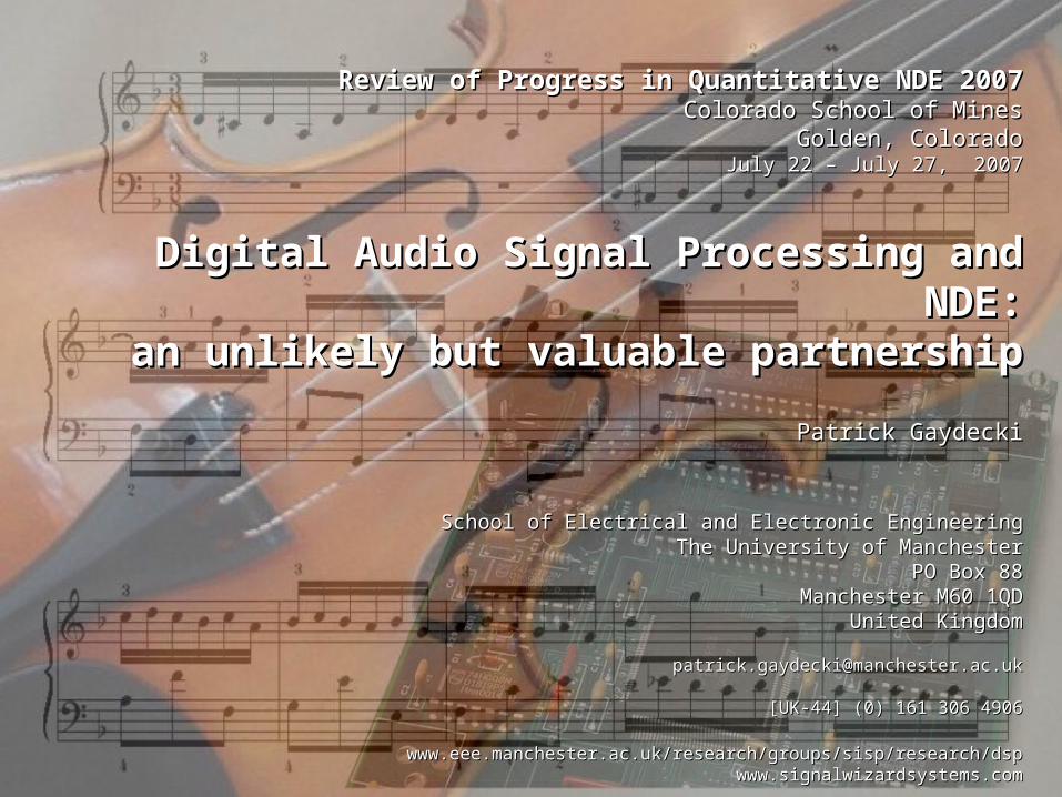
Characteristics of Real-Time DSP Systems
• DSP offers flexibility, allowing a single platform to be rapidly reconfigured for different applications
• Operations such as modulation, phase shifting, signal mixing and delaying are simply performed in software
• System performance is far more accurate than equivalent analogue systems
• However, considerable intellectual investment is required to design and program DSP platforms
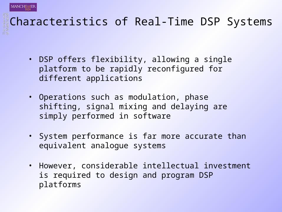
analogue to digital converter
amplifier
loudspeakersystem
10100100100100100111111010101010010010101011010101001010110110101001011010010101010010100101001110100101010100101010010101
PC…PC…
…or DSP system
The Sound Transduction Process:sound energy electrical signal binary processed binary electrical signal sound energy
digital to analogue converter
amplifier
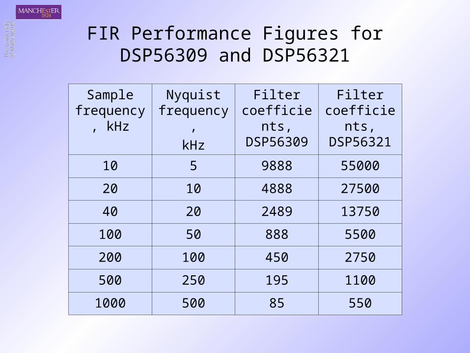
Sample frequency,
kHz
Nyquist frequency,
kHz
Filter coefficients, DSP56309
Filter coefficients, DSP56321
10 5 9888 55000
20 10 4888 27500
40 20 2489 13750
100 50 888 5500
200 100 450 2750
500 250 195 1100
1000 500 85 550
FIR Performance Figures forDSP56309 and DSP56321
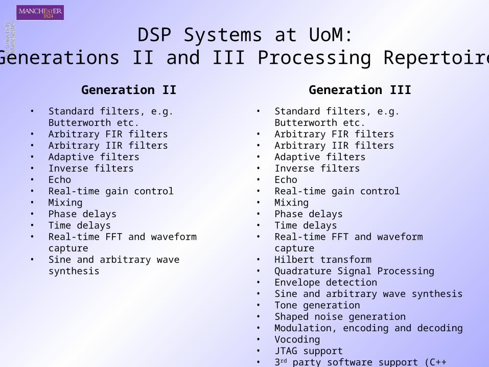
DSP Systems at UoM:Generations II and III Processing Repertoire
• Standard filters, e.g. Butterworth etc.• Arbitrary FIR filters• Arbitrary IIR filters• Adaptive filters• Inverse filters• Echo• Real-time gain control• Mixing• Phase delays• Time delays• Real-time FFT and waveform capture• Sine and arbitrary wave synthesis
• Standard filters, e.g. Butterworth etc.• Arbitrary FIR filters• Arbitrary IIR filters• Adaptive filters• Inverse filters• Echo• Real-time gain control• Mixing• Phase delays• Time delays• Real-time FFT and waveform capture• Hilbert transform• Quadrature Signal Processing• Envelope detection• Sine and arbitrary wave synthesis• Tone generation• Shaped noise generation• Modulation, encoding and decoding• Vocoding• JTAG support• 3rd party software support (C++ design tools)
Generation II Generation III
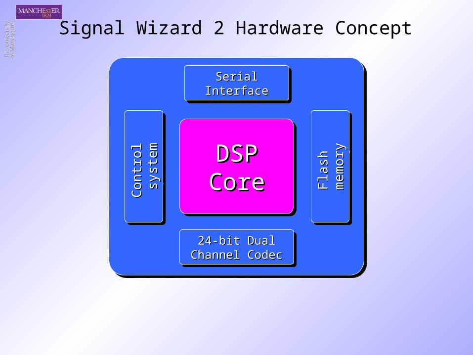
24-bit Dual 24-bit Dual Channel CodecChannel Codec
24-bit Dual 24-bit Dual Channel CodecChannel Codec
Fla
sh
Fla
sh
me
mor
ym
em
ory
Fla
sh
Fla
sh
me
mor
ym
em
ory
Serial InterfaceSerial InterfaceSerial InterfaceSerial Interface
DSPDSPCoreCoreC
on
tro
l C
on
tro
l sy
stem
syst
emC
on
tro
l C
on
tro
l sy
stem
syst
em
Signal Wizard 2 Hardware Concept
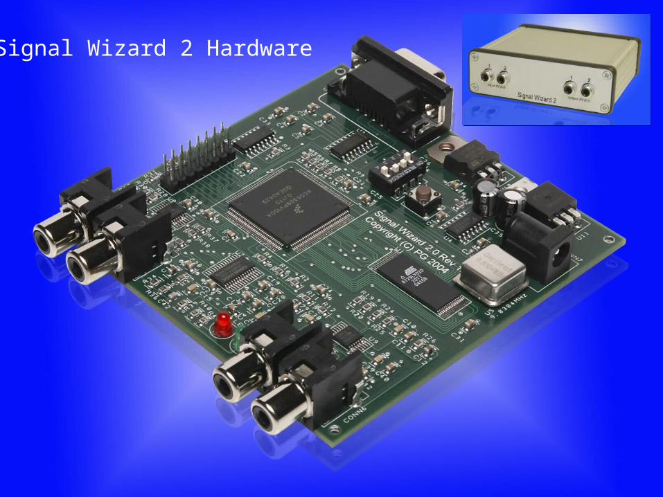
Signal Wizard 2 Hardware
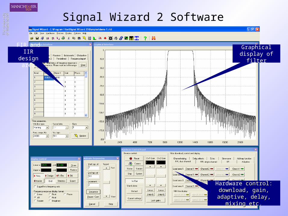
Signal Wizard 2 Software
FIR and IIRdesign area
Graphical display of filter
Hardware control: control: download, gain, adaptive, download, gain, adaptive,
delay, mixing etc.delay, mixing etc.
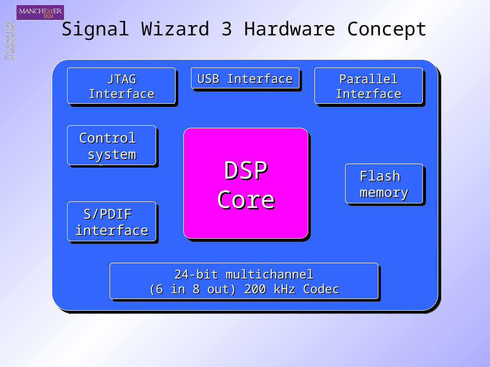
24-bit multichannel24-bit multichannel(6 in 8 out) 200 kHz Codec(6 in 8 out) 200 kHz Codec
24-bit multichannel24-bit multichannel(6 in 8 out) 200 kHz Codec(6 in 8 out) 200 kHz Codec
Flash Flash memorymemoryFlash Flash
memorymemory
USB InterfaceUSB InterfaceUSB InterfaceUSB Interface
DSPDSPCoreCore
Control Control systemsystem
Control Control systemsystem
Signal Wizard 3 Hardware Concept
JTAG InterfaceJTAG InterfaceJTAG InterfaceJTAG Interface Parallel InterfaceParallel InterfaceParallel InterfaceParallel Interface
S/PDIF S/PDIF interfaceinterfaceS/PDIF S/PDIF interfaceinterface
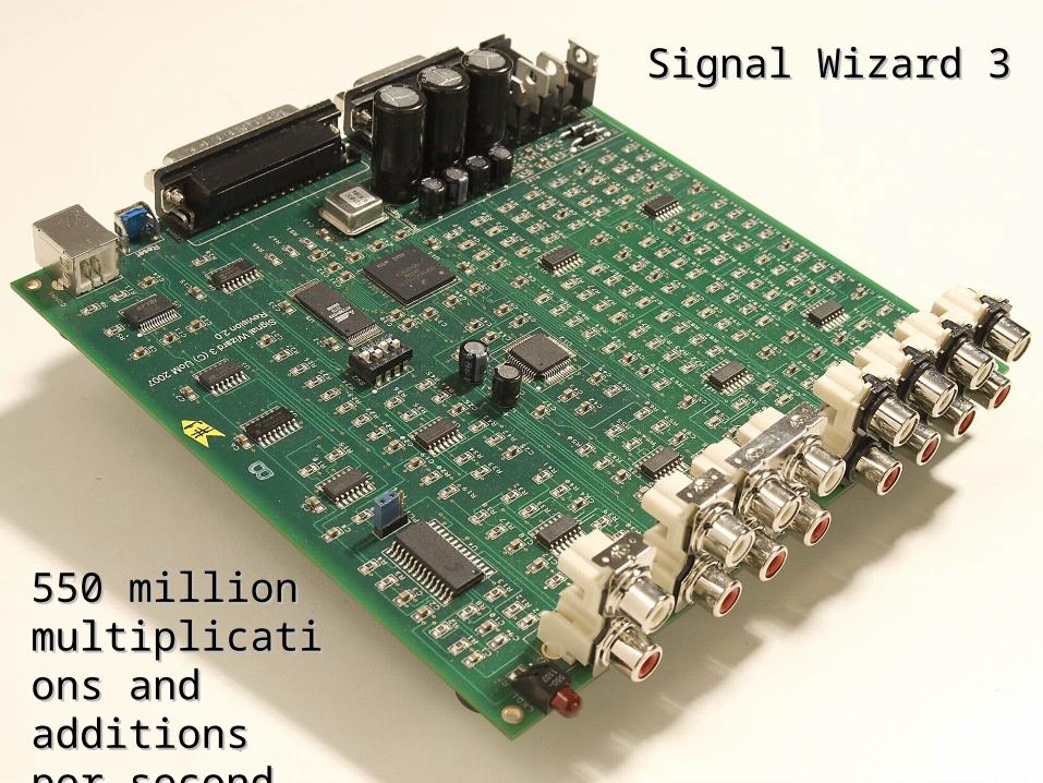
Signal Wizard 3Signal Wizard 3
550 million 550 million multiplications multiplications and additions and additions per secondper second
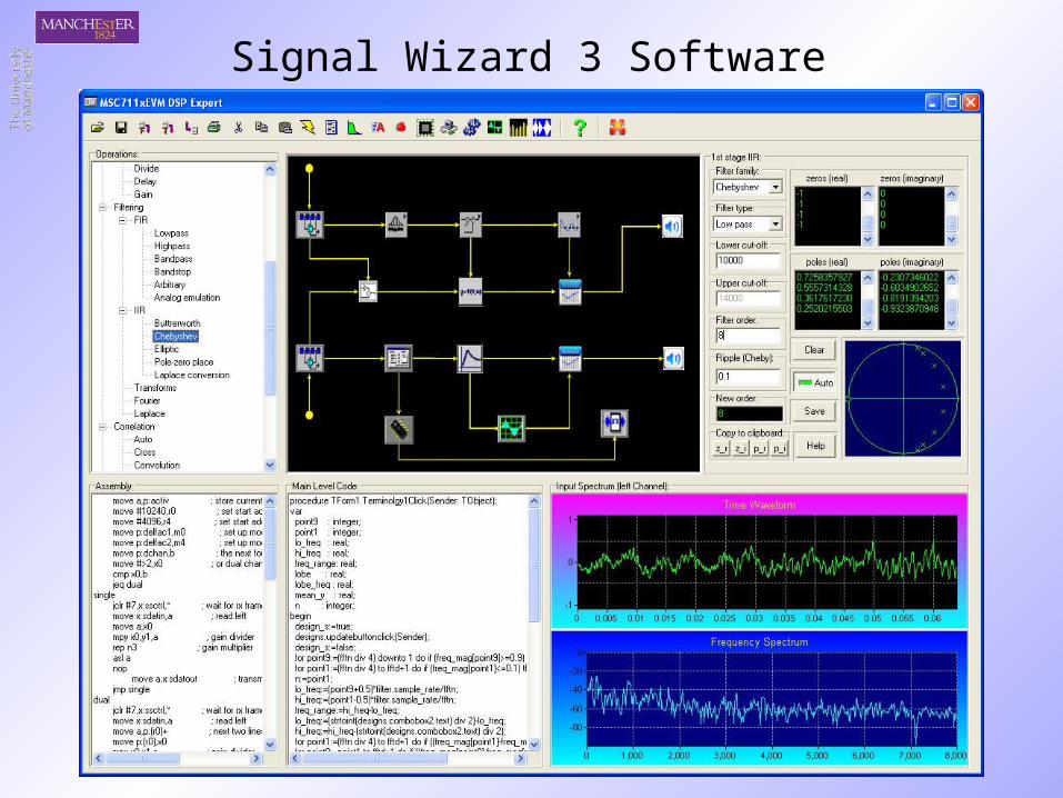
Signal Wizard 3 Software
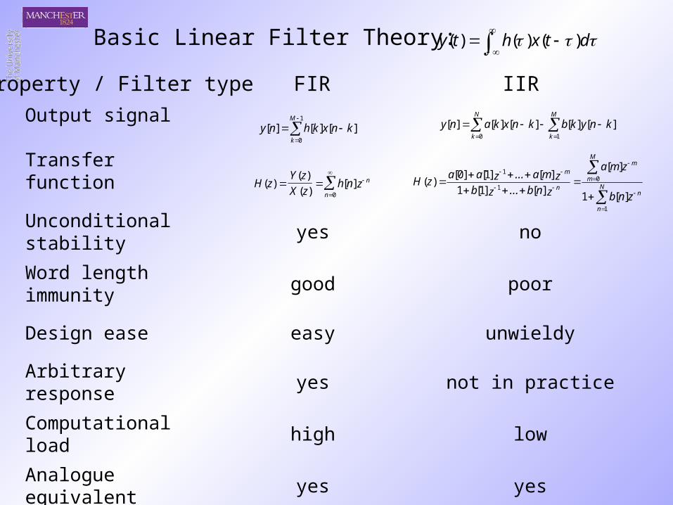
Output signal
Transfer function
Unconditional stability yes no
Word length immunity good poor
Design ease easy unwieldy
Arbitrary response yes not in practice
Computational load high low
Analogue equivalent yes yes
1
0
][][][M
k
knxkhny
H zY z
X zh n z
n
n( )( )
( )[ ]
0
M
k
N
k
knykbknxkany10
][][][][][
N
n
n
M
m
m
n
m
znb
zma
znb...zbzma...zaa
zH
1
01
1
][1
][
][]1[1
][]1[]0[)(
FIRProperty / Filter type IIR
Basic Linear Filter Theory: dtxhty )()()(
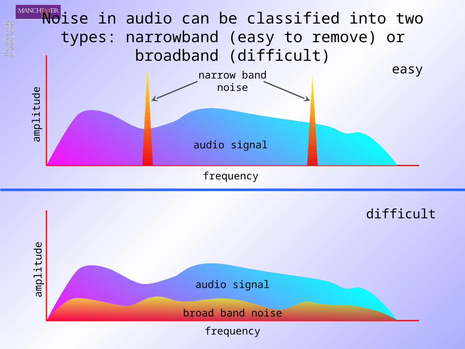
Noise in audio can be classified into two types: narrowband (easy to remove) or broadband (difficult)
frequency
ampl
itude
audio signal
narrow bandnoise
frequency
ampl
itude
audio signal
broad band noise
easy
difficult
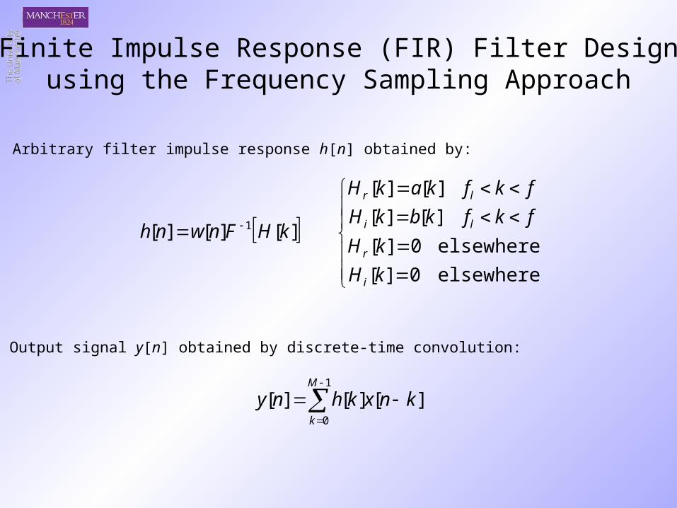
Finite Impulse Response (FIR) Filter Designusing the Frequency Sampling Approach
1
0
][][][M
k
knxkhny
elsewhere0][
elsewhere0][
][][
][][
][][][ 1
kH
kH
fkfkbkH
fkfkakH
kHFnwnh
i
r
li
lr
Arbitrary filter impulse response h[n] obtained by:
Output signal y[n] obtained by discrete-time convolution:
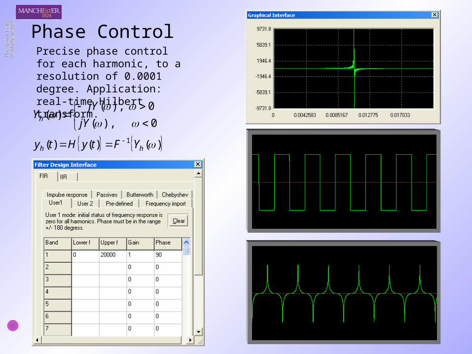
Precise phase control for each harmonic, to a resolution of 0.0001 degree. Application: real-time Hilbert transform.
)()()( 1 hh YFtyHty
0),(
0),()(
jY
jYYh
Phase Control
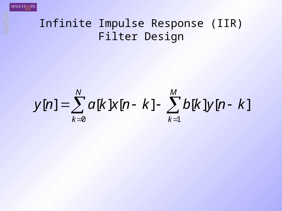
Infinite Impulse Response (IIR) Filter Design
M
k
N
k
knykbknxkany10
][][][][][
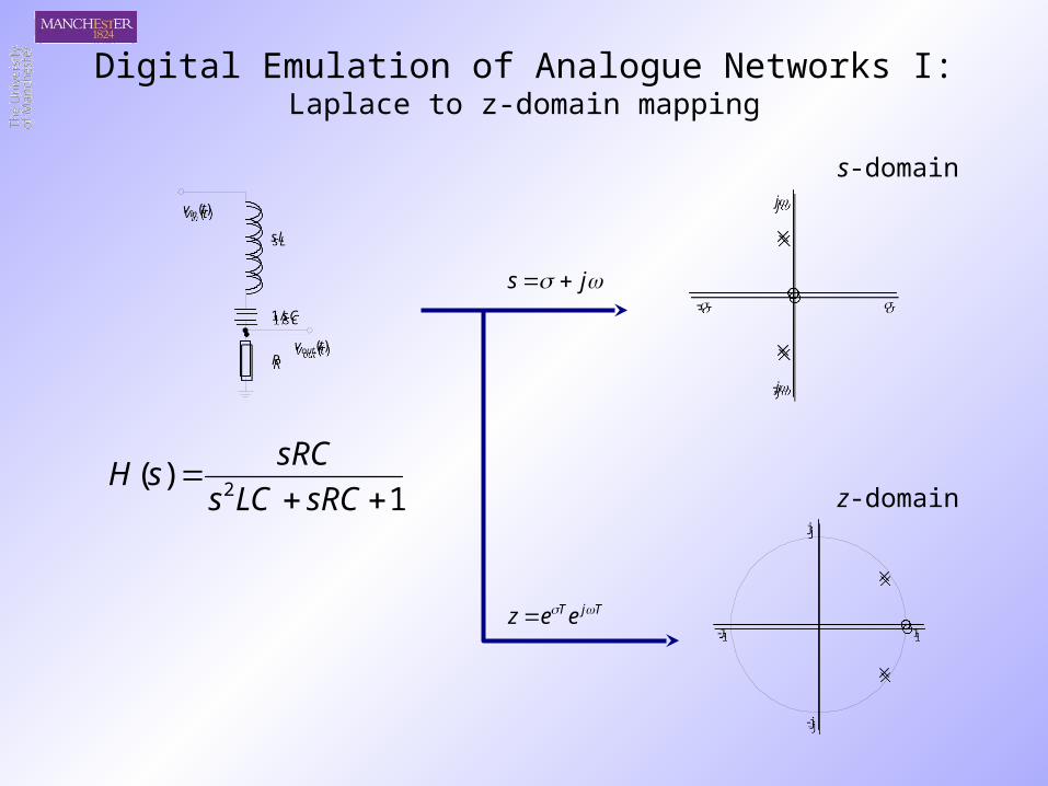
Digital Emulation of Analogue Networks I:Laplace to z-domain mapping
sL
1/sC
R
vin(t)
vout(t)
sL
1/sC
R
vin(t)
vout(t)
j
-j
-
j
-j
-
j
-j
1-1
j
-j
1-1
1)(
2
sRCLCs
sRCsH
s-domain
z-domain
js
TjTeez
1)(
2
sRCLCs
sRCsH
1
1
1
12
z
z
Ts
11
12
1
12
1
12
)(
1
12
1
12
1
1
z
zRC
Tz
zLC
T
z
zRC
TzH
LCT
b
T
RCa
22
2
11
1
1
1
1
1
1
1
)(
1
1
1
1
1
1
1
1
z
za
z
z
z
zb
z
za
zH
21
2
)1()22()1()(
zabzbba
azazH
)1(
)1(
)1(
)22(
)1(
2
1
0
ba
ab
ba
b
ba
a
22
11
20
1
)1()(
zz
zzH
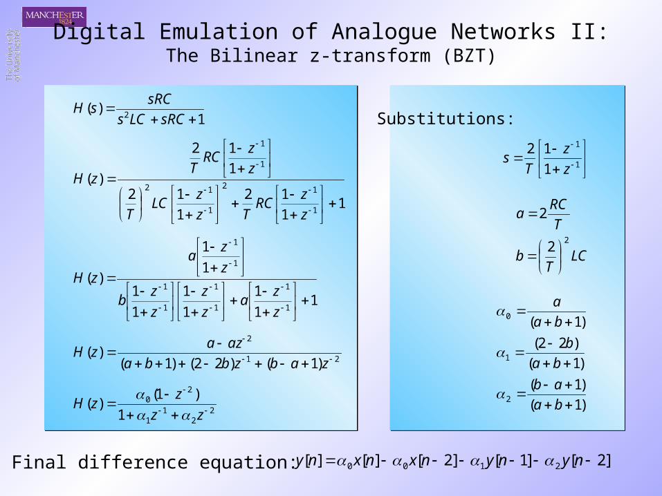
]2[]1[]2[][][ 2100 nynynxnxny
Substitutions:
Digital Emulation of Analogue Networks II:The Bilinear z-transform (BZT)
Final difference equation:
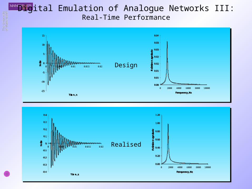
Digital Emulation of Analogue Networks III:Real-Time Performance
-15
-10
-5
0
5
10
15
0 0.005 0.01 0.015 0.02
Time, s
Vo
lts
-15
-10
-5
0
5
10
15
0 0.005 0.01 0.015 0.02
Time, s
Vo
lts
0.00
0.20
0.40
0.60
0.80
1.00
1.20
0 2000 4000 6000 8000 10000
Frequency, Hz
Rel
ativ
e m
agn
itu
de
0.00
0.20
0.40
0.60
0.80
1.00
1.20
0 2000 4000 6000 8000 10000
Frequency, Hz
Rel
ativ
e m
agn
itu
de
-0.4
-0.3
-0.2
-0.1
0
0.1
0.2
0.3
0.4
0 0.005 0.01 0.015 0.02
Time, s
Vo
lts
-0.4
-0.3
-0.2
-0.1
0
0.1
0.2
0.3
0.4
0 0.005 0.01 0.015 0.02
Time, s
Vo
lts
0.00
0.01
0.01
0.02
0.02
0.03
0.03
0.04
0 2000 4000 6000 8000 10000
Frequency, Hz
Rel
ativ
e m
agn
itu
de
0.00
0.01
0.01
0.02
0.02
0.03
0.03
0.04
0 2000 4000 6000 8000 10000
Frequency, Hz
Rel
ativ
e m
agn
itu
de
Design
Realised
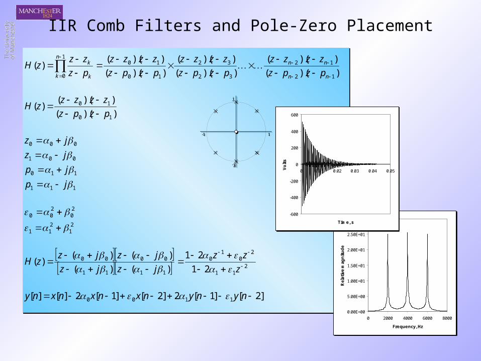
IIR Comb Filters and Pole-Zero Placement
))((
))((
))((
))((
))((
))(()(
12
12
32
32
10
101
0
nn
nnn
k k
k
pzpz
zzzz
pzpz
zzzz
pzpz
zzzz
pz
zzzH
))((
))(()(
10
10
pzpz
zzzzzH
111
110
001
000
jp
jp
jz
jz
21
211
20
200
2
11
20
10
1111
0000
21
21
)()(
)()()(
z
zz
jzjz
jzjzzH
]2[]1[2]2[]1[2][][ 1100 nynynxnxnxny 0.00E+00
5.00E+00
1.00E+01
1.50E+01
2.00E+01
2.50E+01
3.00E+01
0 2000 4000 6000 8000
Frequency, Hz
Rel
ativ
e m
agn
itu
de
0.00E+00
5.00E+00
1.00E+01
1.50E+01
2.00E+01
2.50E+01
3.00E+01
0 2000 4000 6000 8000
Frequency, Hz
Rel
ativ
e m
agn
itu
de
-600
-400
-200
0
200
400
600
0 0.01 0.02 0.03 0.04 0.05
Time, s
Vo
lts
-600
-400
-200
0
200
400
600
0 0.01 0.02 0.03 0.04 0.05
Time, s
Vo
lts
j
-j
1-1
j
-j
1-1
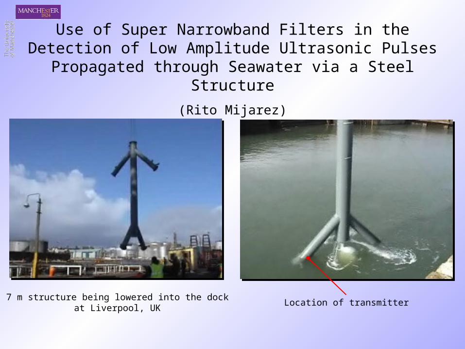
Use of Super Narrowband Filters in the Detection of Low Amplitude Ultrasonic Pulses Propagated through Seawater
via a Steel Structure
(Rito Mijarez)
7 m structure being lowered into the dockat Liverpool, UK
Location of transmitter
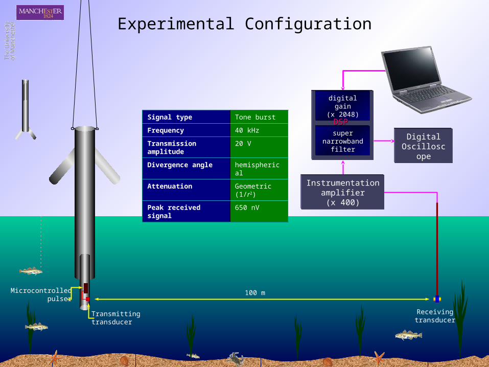
Instrumentationamplifier(x 400)
DigitalOscilloscope
super narrowband
filter
digital gain(x 2048)
DSPDSP
Microcontrolledpulser
Transmittingtransducer
Receivingtransducer
100 m
Signal type Tone burst
Frequency 40 kHz
Transmission amplitude
20 V
Divergence angle hemispherical
Attenuation Geometric (1/r2)
Peak received signal 650 nV
Experimental Configuration
Time
Am
plitu
de
Time
Am
plitu
de
Time
Am
plitu
de
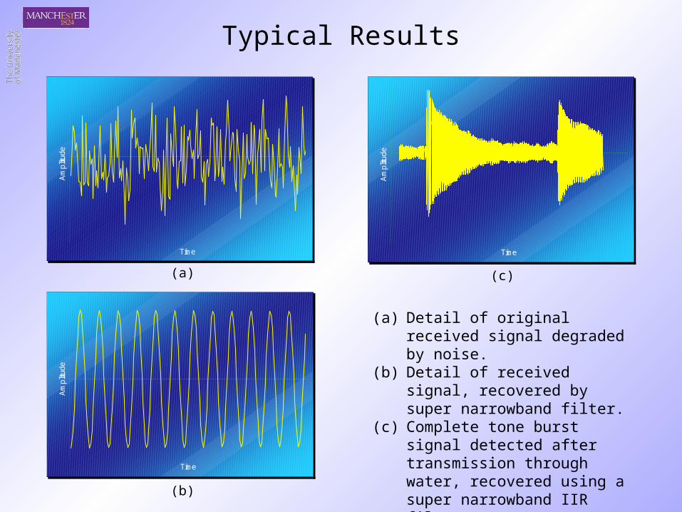
Typical Results
(a) Detail of original received signal degraded by noise.
(b) Detail of received signal, recovered by super narrowband filter.
(c) Complete tone burst signal detected after transmission through water, recovered using a super narrowband IIR filter.
(a)
(b)
(c)
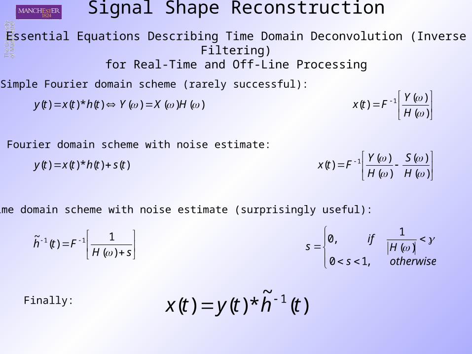
Signal Shape Reconstruction
Essential Equations Describing Time Domain Deconvolution (Inverse Filtering)for Real-Time and Off-Line Processing
)()()()(*)()( HXYthtxty
)(
)()( 1
H
YFtx
)()(*)()( tsthtxty
)(
)(
)(
)()( 1
H
S
H
YFtx
otherwisesH
ifs
,10)(
1,0
sHFth
)(
1)(
~ 11
)(~
*)()( 1 thtytx
Simple Fourier domain scheme (rarely successful):
Fourier domain scheme with noise estimate:
Time domain scheme with noise estimate (surprisingly useful):
Finally:
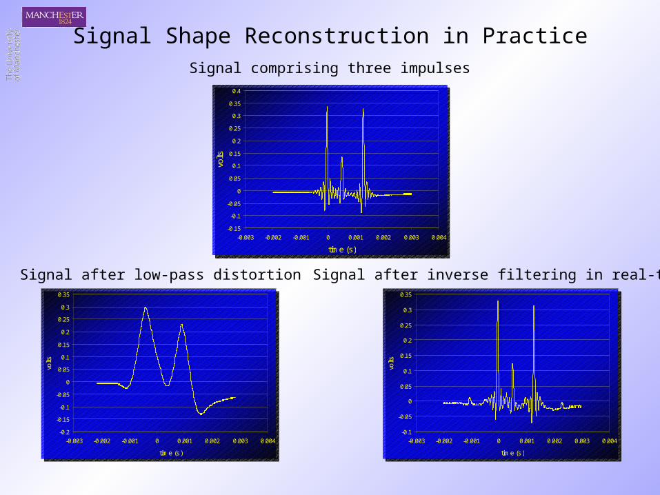
Signal Shape Reconstruction in Practice
-0.2
-0.15
-0.1
-0.05
0
0.05
0.1
0.15
0.2
0.25
0.3
0.35
-0.003 -0.002 -0.001 0 0.001 0.002 0.003 0.004
time (s)
volts
-0.2
-0.15
-0.1
-0.05
0
0.05
0.1
0.15
0.2
0.25
0.3
0.35
-0.003 -0.002 -0.001 0 0.001 0.002 0.003 0.004
time (s)
volts
-0.1
-0.05
0
0.05
0.1
0.15
0.2
0.25
0.3
0.35
-0.003 -0.002 -0.001 0 0.001 0.002 0.003 0.004
time (s)
volts
-0.1
-0.05
0
0.05
0.1
0.15
0.2
0.25
0.3
0.35
-0.003 -0.002 -0.001 0 0.001 0.002 0.003 0.004
time (s)
volts
Signal comprising three impulses
Signal after inverse filtering in real-timeSignal after low-pass distortion
-0.15
-0.1
-0.05
0
0.05
0.1
0.15
0.2
0.25
0.3
0.35
0.4
-0.003 -0.002 -0.001 0 0.001 0.002 0.003 0.004
time (s)
volts
-0.15
-0.1
-0.05
0
0.05
0.1
0.15
0.2
0.25
0.3
0.35
0.4
-0.003 -0.002 -0.001 0 0.001 0.002 0.003 0.004
time (s)
volts
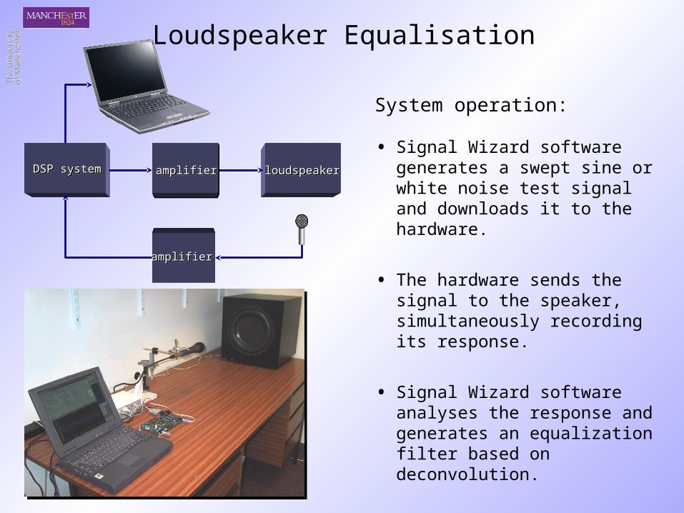
Loudspeaker Equalisation
System operation: • Signal Wizard software generates
a swept sine or white noise test signal and downloads it to the hardware.
• The hardware sends the signal to the speaker, simultaneously recording its response.
• Signal Wizard software analyses the response and generates an equalization filter based on deconvolution.
• The hardware convolves the filter with the test signal and the analysis is repeated.
DSP systemDSP systemDSP systemDSP system
amplifieramplifieramplifieramplifier
amplifieramplifieramplifieramplifier loudspeakerloudspeakerloudspeakerloudspeaker
-90
-85
-80
-75
-70
-65
-60
-55
-50
-45
-40
500 1000 1500 2000 2500 3000 3500
Frequency, Hz
Re
lati
ve
Inte
ns
ity
, dB
-90
-85
-80
-75
-70
-65
-60
-55
-50
-45
-40
500 1000 1500 2000 2500 3000 3500
Frequency, Hz
Re
lati
ve
Inte
ns
ity
, dB
-90
-85
-80
-75
-70
-65
-60
-55
-50
-45
-40
500 1000 1500 2000 2500 3000 3500
Frequency, Hz
Re
lati
ve
Inte
ns
ity
, dB
-90
-85
-80
-75
-70
-65
-60
-55
-50
-45
-40
500 1000 1500 2000 2500 3000 3500
Frequency, Hz
Re
lati
ve
Inte
ns
ity
, dB
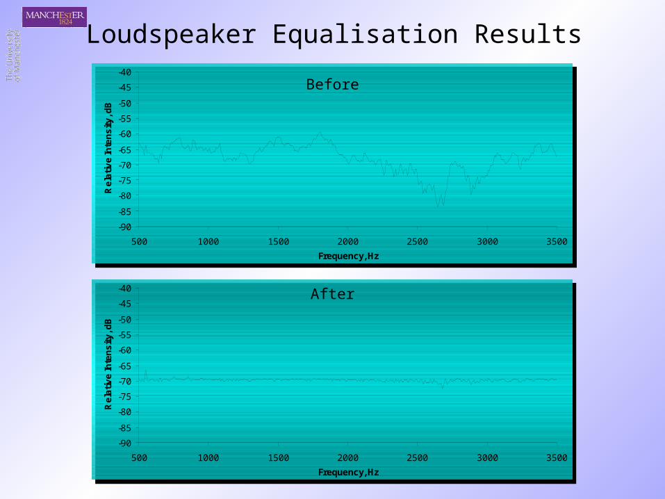
Loudspeaker Equalisation Results
After
Before

Noise in audio can be classified into two types: narrowband (easy to remove) or broadband (difficult)
frequency
ampl
itude
audio signal
narrow bandnoise
frequency
ampl
itude
audio signal
broad band noise
easy
difficult
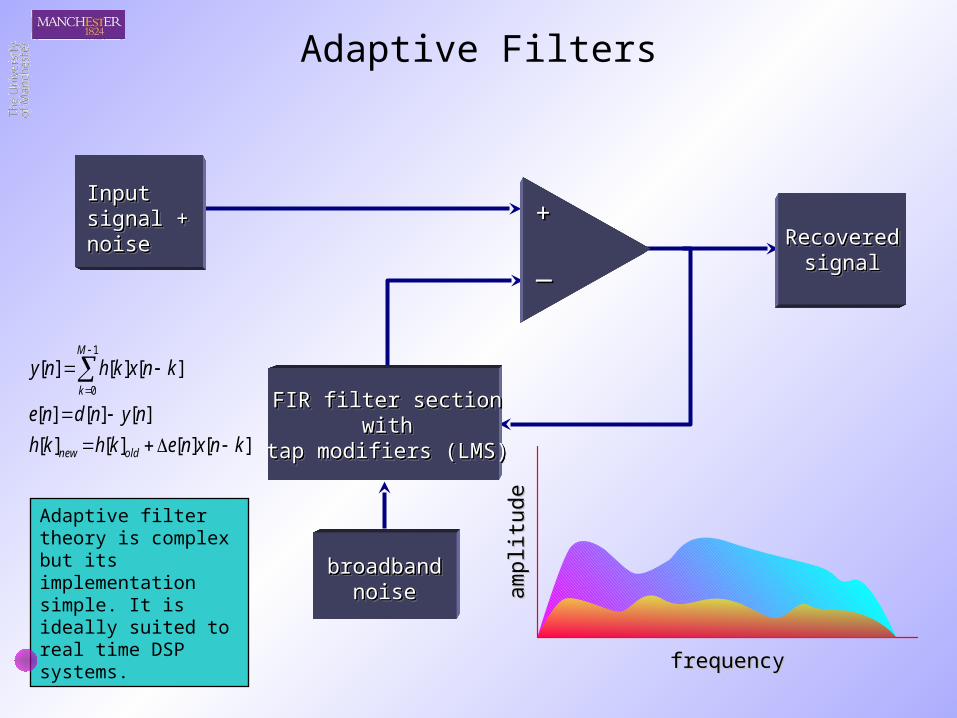
Adaptive Filters
broadbandbroadbandnoisenoise
broadbandbroadbandnoisenoise
FIR filter sectionFIR filter sectionwithwith
tap modifiers (LMS)tap modifiers (LMS)
FIR filter sectionFIR filter sectionwithwith
tap modifiers (LMS)tap modifiers (LMS)
++
__
frequencyfrequency
ampl
itude
ampl
itude
RecoveredRecoveredsignalsignal
RecoveredRecoveredsignalsignal
][][][][
][][][
][][][1
0
knxnekhkh
nyndne
knxkhny
oldnew
M
k
InputInputsignal +signal +noisenoise
InputInputsignal +signal +noisenoise
Adaptive filter theory is complex but its implementation simple. It is ideally suited to real time DSP systems.
Conclusions
• Flexibility ensures that real time DSP is suitable for many applications in both real time NDE and audio signal processing
• Software-realized processing yields very significant improvements with regard to stability, precision and repeatability
• New generation DSP devices are extending the range of signal
frequencies over which real time discrete processing can be applied