Embed Size (px)
Citation preview
Journal of Chromatography A, 1065 (2005) 145–168
Review
Golden rules and pitfalls in selecting optimum conditions forhigh-speed counter-current chromatography
Yoichiro Ito∗
Center of Biochemistry and Biophysics, National Heart, Lung, and Blood Institute, National Institutes of Health,Building 50, Room 3334, 50 South Drive MSC 8014, Bethesda, MD 20892-8014, USA
Received 16 July 2003; received in revised form 24 November 2004; accepted 8 December 2004Available online 25 January 2005
Abstract
This paper aims to be an aid to those chemists who are interested in utilizing high-speed counter-current chromatography (HSCCC), which isfree of irreversible adsorption and offers high resolution comparable to column chromatography. It explains the selection of HSCCC conditionsstep by step including the selection of two-phase solvent systems, determination of partition coefficient (K) of analytes, preparation of two-
he paperensively
mmercialr-current
Parti
phase solvent system and sample solution, selection of elution mode, flow rate, rotation speed, and on-line monitoring of the eluate. Tcovers both standard HSCCC and pH-zone-refining CCC techniques. Technical terms (italic) unfamiliar to the beginner are comprehexplained in Glossary. Various examples of two-phase solvent systems used in HSCCC are listed in Appendices A and B. The cosources of HSCCC and other CCC instruments are described in detail in the study edited by Berthod [A. Berthod (Ed.), CounteChromatography, Elsevier, Amsterdam, 2003].Published by Elsevier B.V. All rights reserved.
Keywords:High-speed counter-current chromatography; pH-zone-refining counter-current chromatography; Type-J multilayer coil planet centrifuge;tioncoefficient; On-line monitoring; Retention of stationary phase
Contents
1. Introduction. . . . . . . . . . . . . . . . . . . . . . . . . . . . . . . . . . . . . . . . . . . . . . . . . . . . . . . . . . . . . . . . . . . . . . . . . . . . . . . . . . . . . . . . . . . . . . . . . . . . . . . . . 1462. Standard high-speed counter-current chromatography using type-J multilayer coil planet centrifuge. . . . . . . . . . . . . . . . . . . . . . . . . . 146
2.1. Mechanism. . . . . . . . . . . . . . . . . . . . . . . . . . . . . . . . . . . . . . . . . . . . . . . . . . . . . . . . . . . . . . . . . . . . . . . . . . . . . . . . . . . . . . . . . . . . . . . . . . . 1462.2. Selection of the two-phase solvent system. . . . . . . . . . . . . . . . . . . . . . . . . . . . . . . . . . . . . . . . . . . . . . . . . . . . . . . . . . . . . . . . . . . . . . . . 148
2.2.1. Partition coefficient. . . . . . . . . . . . . . . . . . . . . . . . . . . . . . . . . . . . . . . . . . . . . . . . . . . . . . . . . . . . . . . . . . . . . . . . . . . . . . . . . . . . 1482.2.2. Retention of the stationary phase. . . . . . . . . . . . . . . . . . . . . . . . . . . . . . . . . . . . . . . . . . . . . . . . . . . . . . . . . . . . . . . . . . . . . . . . 149
2.3. Sample solution. . . . . . . . . . . . . . . . . . . . . . . . . . . . . . . . . . . . . . . . . . . . . . . . . . . . . . . . . . . . . . . . . . . . . . . . . . . . . . . . . . . . . . . . . . . . . . . 1502.4. Separation column. . . . . . . . . . . . . . . . . . . . . . . . . . . . . . . . . . . . . . . . . . . . . . . . . . . . . . . . . . . . . . . . . . . . . . . . . . . . . . . . . . . . . . . . . . . . . 1502.5. Choice of the mobile phase. . . . . . . . . . . . . . . . . . . . . . . . . . . . . . . . . . . . . . . . . . . . . . . . . . . . . . . . . . . . . . . . . . . . . . . . . . . . . . . . . . . . . 1512.6. Flow rate of the mobile phase. . . . . . . . . . . . . . . . . . . . . . . . . . . . . . . . . . . . . . . . . . . . . . . . . . . . . . . . . . . . . . . . . . . . . . . . . . . . . . . . . . . 1512.7. Revolution speed. . . . . . . . . . . . . . . . . . . . . . . . . . . . . . . . . . . . . . . . . . . . . . . . . . . . . . . . . . . . . . . . . . . . . . . . . . . . . . . . . . . . . . . . . . . . . . 1512.8. Filling the column with the stationary phase. . . . . . . . . . . . . . . . . . . . . . . . . . . . . . . . . . . . . . . . . . . . . . . . . . . . . . . . . . . . . . . . . . . . . . 1512.9. Sample loading. . . . . . . . . . . . . . . . . . . . . . . . . . . . . . . . . . . . . . . . . . . . . . . . . . . . . . . . . . . . . . . . . . . . . . . . . . . . . . . . . . . . . . . . . . . . . . . . 1522.10. On-line monitoring of effluent. . . . . . . . . . . . . . . . . . . . . . . . . . . . . . . . . . . . . . . . . . . . . . . . . . . . . . . . . . . . . . . . . . . . . . . . . . . . . . . . . 1522.11. Measurement of stationary phase retention. . . . . . . . . . . . . . . . . . . . . . . . . . . . . . . . . . . . . . . . . . . . . . . . . . . . . . . . . . . . . . . . . . . . . . 152
∗ Tel.: +1 301 496 1210; fax: +1 310 402 3404.E-mail address:[email protected].
0021-9673/$ – see front matter. Published by Elsevier B.V. All rights reserved.doi:10.1016/j.chroma.2004.12.044
146 Y. Ito / J. Chromatogr. A 1065 (2005) 145–168
3. pH-zone-refining counter-current chromatography. . . . . . . . . . . . . . . . . . . . . . . . . . . . . . . . . . . . . . . . . . . . . . . . . . . . . . . . . . . . . . . . . . . . . . . 1533.1. Mechanism. . . . . . . . . . . . . . . . . . . . . . . . . . . . . . . . . . . . . . . . . . . . . . . . . . . . . . . . . . . . . . . . . . . . . . . . . . . . . . . . . . . . . . . . . . . . . . . . . . . 1533.2. Selection of the solvent system for pH-zone-refining CCC. . . . . . . . . . . . . . . . . . . . . . . . . . . . . . . . . . . . . . . . . . . . . . . . . . . . . . . . . 1543.3. Optimization of separation condition. . . . . . . . . . . . . . . . . . . . . . . . . . . . . . . . . . . . . . . . . . . . . . . . . . . . . . . . . . . . . . . . . . . . . . . . . . . . 1553.4. Sample solution. . . . . . . . . . . . . . . . . . . . . . . . . . . . . . . . . . . . . . . . . . . . . . . . . . . . . . . . . . . . . . . . . . . . . . . . . . . . . . . . . . . . . . . . . . . . . . . 1553.5. Separation procedure. . . . . . . . . . . . . . . . . . . . . . . . . . . . . . . . . . . . . . . . . . . . . . . . . . . . . . . . . . . . . . . . . . . . . . . . . . . . . . . . . . . . . . . . . . . 155
4. Conclusion. . . . . . . . . . . . . . . . . . . . . . . . . . . . . . . . . . . . . . . . . . . . . . . . . . . . . . . . . . . . . . . . . . . . . . . . . . . . . . . . . . . . . . . . . . . . . . . . . . . . . . . . . . 156Acknowledgment. . . . . . . . . . . . . . . . . . . . . . . . . . . . . . . . . . . . . . . . . . . . . . . . . . . . . . . . . . . . . . . . . . . . . . . . . . . . . . . . . . . . . . . . . . . . . . . . . . . . . . . . 156References. . . . . . . . . . . . . . . . . . . . . . . . . . . . . . . . . . . . . . . . . . . . . . . . . . . . . . . . . . . . . . . . . . . . . . . . . . . . . . . . . . . . . . . . . . . . . . . . . . . . . . . . . . . . . . 165Glossary. . . . . . . . . . . . . . . . . . . . . . . . . . . . . . . . . . . . . . . . . . . . . . . . . . . . . . . . . . . . . . . . . . . . . . . . . . . . . . . . . . . . . . . . . . . . . . . . . . . . . . . . . . . . . . . . 166
1. Introduction
In the early 1970s, a new separation technique calledcounter-current chromatography1 (CCC) was developed.The method provides an advantage over the conventionalcolumn chromatography by eliminating the use of a solidsupport where an amount of stationary phase is limited anddangers of irreversible adsorption from the support are in-evitably present. As usual in the development of new meth-ods, the early models had various problems: the first modelcalled helix CCC (now called toroidal coil CCC)[1,2] hada rotary seal and the effluent was introduced from the ro-tating syringe. This analytical model yielded thousands oftheoretical plates(TPs), but it required an overnight run. Thesecond model called droplet CCC[2,3] produced a prepara-tive separation at near 1000 TPs, but separating 30 mg of atest sample required 3 days. Unfortunately, the performanceof these early models produced a long-standing false imagethat CCC is a time-consuming technique. In the interveningyears, the method has been radically improved in terms ofresolution, separation time and sample loading capacity bythe development ofhigh-speed CCC(HSCCC)[4–7], whichyields a highly efficient separation of multigram quantitiesof samples in several hours. HSCCC, which is one form ofCCC, is now accepted as an efficient preparative technique,a iousn
omes ctiono ationp col-u rs, anc tn phicj ringt s ared ries,p cticala l de-t i.e.,
how to select a suitable solvent system, how to prepare thesample solution, how to determine the inlet and outlet of thecolumn, how to select the direction and the rotation speedof the apparatus, how to monitor the effluent, etc. Althoughthese procedures are obvious for scientists routinely work-ing on CCC separations, a misuse of one facet may lead tounsuccessful separations and this might well discourage onefrom continued use of the method.
The purpose of this article is to explain comprehensivelythe practical CCC procedures for beginners so that they canquickly learn how to use the HSCCC instrument under opti-mum conditions. To ease understanding the techniques, themechanisms of both standard HSCCC andpH-zone-refiningCCCare briefly described with illustrations.
2. Standard high-speed counter-currentchromatography using type-J multilayer coil planetcentrifuge
2.1. Mechanism
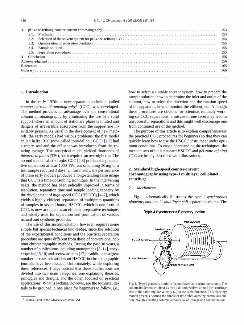
Fig. 1 schematically illustratesthe type-J synchronousplanetary motionof amultilayer coilseparation column. The
F . Thec trifugea rym elu-t ion.
nd widely used for separation and purification of varatural and synthetic products.
The use of this instrumentation, however, requires simple but special technical knowledge, since the selef the experimental conditions and the practical separrocedure are quite different from those of conventionalmn chromatographic methods. During the past 30 yeaumber of publications including monographs[8–14], ency-lopedia[15,16]and review articles[17] in addition to a greaumber of research articles on HSCCC in chromatogra
ournals have been issued. Unfortunately, while explohese references, I have noticed that these publicationivided into two main categories, one explaining theorinciples and designs, and the other, focused on prapplications. What is lacking, however, are the technica
ails to be grouped in one place for beginners to follow,
1 Terms listed in the Glossary are italicised.
ig. 1. Type-J planetary motion of a multilayer coil separation columnolumn holder rotates about its own axis and revolves around the cenxis at the same angular velocity (ω) in the same direction. This planetaotion prevents twisting the bundle of flow tubes allowing continuous
ion through a rotating column without risk of leakage and contaminat
Y. Ito / J. Chromatogr. A 1065 (2005) 145–168 147
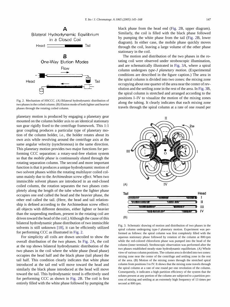
Fig. 2. Mechanism of HSCCC. (A) Bilateral hydrodynamic distribution oftwo phases in the coiled column. (B) Elution mode of both lighter and heavierphases through the rotating coiled column.
planetary motion is produced by engaging a planetary gearmounted on the column holder axis to an identical stationarysun gear rigidly fixed to the centrifuge framework. This 1:1gear coupling produces a particular type of planetary mo-tion of the column holder, i.e., the holder rotates about itsown axis while revolving around the centrifuge axis at thesame angular velocity (synchronous) in the same direction.This planetary motion provides two major functions for per-forming CCC separation: a rotary-seal-free elution systemso that themobile phaseis continuously eluted through therotating separation column. The second and more importantfunction is that it produces a unique hydrodynamic motion oftwo solvent phases within the rotating multilayer coiled col-umn mainly due to theArchimedean screw effect. When twoimmiscible solvent phases are introduced in an end-closedcoiled column, the rotation separates the two phases com-pletely along the length of the tube where the lighter phaseoccupies one end called the head and the heavier phase, thother end called the tail. (Here, the head and tail relation-ship is defined according to the Archimedean screw effect:all objects with different densities, either lighter or heavierthan the suspending medium, present in the rotating coil aredriven toward the head of the coil.) Although the cause of thisbilateral hydrodynamic phase distribution of two immisciblesolvents is still unknown[18], it can be efficiently utilizedf
theoa thet hase)o e) thet asei ands ovet sedf te the
black phase from the head end (Fig. 2B, upper diagram).Similarly, the coil is filled with the black phase followedby pumping the white phase from the tail (Fig. 2B, lowerdiagram). In either case, the mobile phase quickly movesthrough the coil, leaving a large volume of the other phasestationary in the coil.
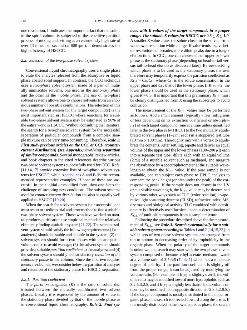
The motion and distribution of the two phases in the ro-tating coil were observed under stroboscopic illumination,and are schematically illustrated inFig. 3A, where a spiralcolumn undergoestype-J planetary motion. (Experimentalconditions are described in the figure caption.) The area inthe spiral column is divided into two zones: the mixing zoneoccupying about one quarter of the area near the center of rev-olution and the settling zone in the rest of the area. InFig. 3B,the spiral column is stretched and arranged according to thepositions I–IV to visualize the motion of the mixing zonesalong the tubing. It clearly indicates that each mixing zonetravels through the spiral column at a rate of one round per
F n thespiral column undergoing type-J planetary motion. Experiment was per-formed as follows: the spiral column was first completely filled with theaqueous stationary phase followed by rotation of the column at 800 rpmwhile the red-colored chloroform phase was pumped into the head of thecolumn (inner terminal). Stroboscopic observation was performed after thetwo phases established steady-state hydrodynamic equilibrium. (A) Wholeview of various column positions. The column area is divided into two zones:mixing zone near the center of the centrifuge and settling zone in the restof the area. (B) Motion of the mixing zones through the stretched spiralcolumn from positions I to IV. It shows that the mixing zone travels throughthe spiral column at a rate of one round per one revolution of the column.Consequently, it indicates a high partition efficiency of the system that thesolutes present at any portion of the column are subjected to a partition pro-cess of mixing and settling at an extremely high frequency of 13 times persecond at 800 rpm.
or performing CCC as illustrated inFig. 2.For simplicity all coils are drawn uncoiled to show
verall distribution of the two phases. InFig. 2A, the coilt the top shows bilateral hydrodynamic distribution of
wo phases in the coil where the white phase (head pccupies the head half and the black phase (tail phas
ail half. This condition clearly indicates that white phntroduced at the tail end will move toward the headimilarly the black phase introduced at the head will moward the tail. This hydrodynamic trend is effectively uor performing CCC as shown inFig. 2B. The coil is firsntirely filled with the white phase followed by pumping
e
ig. 3. Schematic drawing of motion and distribution of two phases i
148 Y. Ito / J. Chromatogr. A 1065 (2005) 145–168
one revolution. It indicates the important fact that the solutein the spiral column is subjected to the repetitive partitionprocess of mixing and settling at an enormously high rate ofover 13 times per second (at 800 rpm). It demonstrates thehigh efficiency of HSCCC.
2.2. Selection of the two-phase solvent system
Conventional liquid chromatography uses a single phaseto elute the analytes released from the adsorptive or liquidphase coated solid support. In contrast, the CCC techniqueuses atwo-phase solvent systemmade of a pair of mutu-ally immiscible solvents, one used as thestationary phaseand the other as themobile phase. The use of two-phasesolvent systems allows one to choose solvents from an enor-mous number of possible combinations. The selection of thistwo-phase solvent system for the target compound(s) is themost important step in HSCCC where searching for a suit-able two-phase solvent system may be estimated as 90% ofthe entire work in HSCCC. Without consulting the literature,the search for a two-phase solvent system for the successfulseparation of particular compounds from a complex sam-ple mixture can be very time-consuming. Therefore,Rule 1:First study previous articles on the CCC or CCD (counter-current distribution) (see Appendix) involving separationo es,a rioust Refs.[ ys-t -m suc-c thec emsu lla
l, onem tablet natu-r velye l-v ) thea ) thes tablev ouldp 4)ts re-m lytesa tion.
2-
t entp te int e asi
tems with K values of the target compounds in a properrange: The suitable K values for HSCCC are 0.5≤K≤1.0.A smallerK value elutes the solute closer to the solvent frontwith lower resolution while a largerK value tends to give bet-ter resolution but broader, more dilute peaks due to a longerelution time. In CCC, one can choose either upper or lowerphase as the stationary phase (depending on head-to-tail ver-sus tail-to-head elution as discussed later). Before decidingwhich phase is to be used as the stationary phase, the usertherefore may temporarily express the partition coefficient asKU/L =CU/CL, whereCU is the solute concentration in theupper phase andCL, that of the lower phase. IfKU/L = 2, thelower phase should be used as the stationary phase, whichgivesK= 0.5. It is important that this preliminaryKU/L mustbe clearly distinguished fromK using the subscripts to avoidconfusion.
The measurement of theKU/L values may be performedas follows: Add a small amount (typically a few milligramsor less depending on its extinction coefficient or absorptiv-ity) of each target compound (one at a time unless quantifiedlater in the two phases by HPLC) to the two mutually equili-brated solvent phases (1–2 ml each) in a stoppered test tube(13 mm× 100 mm). Thoroughly mix with a vortex to equili-brate the contents. After settling, pipette and deliver an equalvolume of the upper and the lower phases (100–200�l) eachinto a separate test tube, dilute each with an equal volume(2 ml) of a suitable solvent such as methanol, and measurethe absorbance by a spectrophotometer at the suitable wave-length to obtain theKU/L value. If the pure sample is notavailable, one can subject each phase to HPLC analysis tocompare the peak height (or area under the peak) of the cor-responding peaks. If the sample does not absorb in the UVor at a visible wavelength, theKU/L value may be determinedby various other ways such as TLC (color reaction), evapo-rative light scattering detector (ELSD), refractive index, MS,dry mass and biological activity. TLC combined with densit-ometry is effectively used for simultaneous determination ofKU/L of multiple components from a sample mixture.
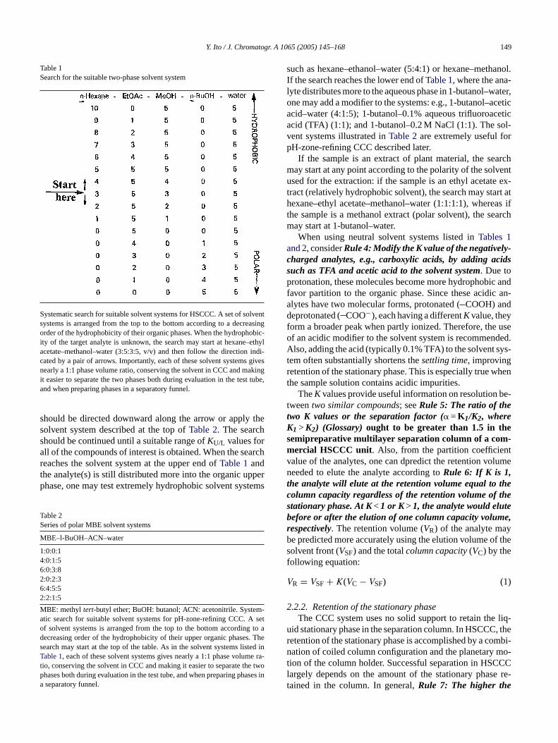
Following the procedure described above for the measure-ment ofKU/L, seeRule 3: Search systematically for a suit-able solvent systemaccording toTables 1 and 2 [14,15,23], inwhich sets of two-phase solvent systems are arranged fromtop to bottom in decreasing order of hydrophobicity in theorganic phase. When the polarity of the target compoundsis unknown, the search may start with the two-phase solventsystem composed of hexane–ethyl acetate–methanol–waterat a volume ratio of 3:5:3:5 (Table 1) which has a moderatedegree of polarity. If the partition coefficient is slightly offfrom the proper range, it can be adjusted by modifying thevolume ratio. (For example, ifKU/L is slightly over 2, the vol-ume ratio may be modified toward more hydrophobic such as3.2:5:3.2:5, and ifKU/L is slightly less than 0.5, the volume ra-tion may be modified in the opposite direction to 2.8:5:2.8:5.)If the target compound is mostly distributed in the upper or-ganic phase, the search is directed upward along the arrow. Ifit is mostly distributed in the lower aqueous phase, the search
f similar compounds. Several monographs, review articlnd book chapters in the cited references describe va
wo-phase solvent systems successfully used for CCC.11,14,17]provide extensive lists of two-phase solvent sems for HSCCC, whileAppendices A and Blist the recomended representative examples. If none of these are
essful in their initial or modified form, then one faceshallenge of inventing new conditions. The solvent systsed forcounter-current distributioncan also be equally wepplied to HSCCC[19,20].
When the search for a solvent system is unsuccessfuust resort to a tedious trial and error method to find a sui
wo-phase solvent system. Those who have worked onal products purification use empirical methods for relatifficiently finding a suitable system[21,22]. The selected soent system should satisfy the following requirements: (1nalyte(s) should be stable and soluble in the system; (2olvent system should form two phases with an accepolume ratios to avoid wastage; (3) the solvent system shrovide a suitablepartition coefficientto the analytes; and (
he solvent system should yield satisfactoryretention of thetationary phasein the column. Since the first two requients are obvious, we consider below the partition of anand retention of the stationary phase for HSCCC separa
.2.1. Partition coefficientThe partition coefficient(K) is the ratio of solute dis
ributed between the mutually equilibrated two solvhases. Usually it is expressed by the amount of solu
he stationary phase divided by that of the mobile phasn conventional liquid chromatography.Rule 2: Find sys-
Y. Ito / J. Chromatogr. A 1065 (2005) 145–168 149
Table 1Search for the suitable two-phase solvent system
Systematic search for suitable solvent systems for HSCCC. A set of solventsystems is arranged from the top to the bottom according to a decreasingorder of the hydrophobicity of their organic phases. When the hydrophobic-ity of the target analyte is unknown, the search may start at hexane–ethylacetate–methanol–water (3:5:3:5, v/v) and then follow the direction indi-cated by a pair of arrows. Importantly, each of these solvent systems givesnearly a 1:1 phase volume ratio, conserving the solvent in CCC and makingit easier to separate the two phases both during evaluation in the test tube,and when preparing phases in a separatory funnel.
should be directed downward along the arrow or apply thesolvent system described at the top ofTable 2. The searchshould be continued until a suitable range ofKU/L values forall of the compounds of interest is obtained. When the searchreaches the solvent system at the upper end ofTable 1andthe analyte(s) is still distributed more into the organic upperphase, one may test extremely hydrophobic solvent systems
Table 2Series of polar MBE solvent systems
MBE–l-BuOH–ACN–water
1:0:0:14:0:1:56:0:3:82:0:2:36:4:5:52:2:1:5
MBE: methyl tert-butyl ether; BuOH: butanol; ACN: acetonitrile. System-atic search for suitable solvent systems for pH-zone-refining CCC. A setof solvent systems is arranged from the top to the bottom according to adecreasing order of the hydrophobicity of their upper organic phases. Thesearch may start at the top of the table. As in the solvent systems listed inTable 1, each of these solvent systems gives nearly a 1:1 phase volume ra-tio, conserving the solvent in CCC and making it easier to separate the twophases both during evaluation in the test tube, and when preparing phases ina separatory funnel.
such as hexane–ethanol–water (5:4:1) or hexane–methanol.If the search reaches the lower end ofTable 1, where the ana-lyte distributes more to the aqueous phase in 1-butanol–water,one may add a modifier to the systems: e.g., 1-butanol–aceticacid–water (4:1:5); 1-butanol–0.1% aqueous trifluoroaceticacid (TFA) (1:1); and 1-butanol–0.2 M NaCl (1:1). The sol-vent systems illustrated inTable 2are extremely useful forpH-zone-refining CCC described later.
If the sample is an extract of plant material, the searchmay start at any point according to the polarity of the solventused for the extraction: if the sample is an ethyl acetate ex-tract (relatively hydrophobic solvent), the search may start athexane–ethyl acetate–methanol–water (1:1:1:1), whereas ifthe sample is a methanol extract (polar solvent), the searchmay start at 1-butanol–water.
When using neutral solvent systems listed inTables 1and 2, considerRule 4:Modify the K value of the negatively-charged analytes, e.g., carboxylic acids, by adding acidssuch as TFA and acetic acid to the solvent system. Due toprotonation, these molecules become more hydrophobic andfavor partition to the organic phase. Since these acidic an-alytes have two molecular forms, protonated (COOH) anddeprotonated (COO−), each having a differentK value, theyform a broader peak when partly ionized. Therefore, the useof an acidic modifier to the solvent system is recommended.A ys-tr hent
be-ttKs -m tv lument hec thes eb e,r yb f thesf
V
2liq-
u , ther mbi-n mo-t CCl e re-t
lso, adding the acid (typically 0.1% TFA) to the solvent sem often substantially shortens thesettling time, improvingetention of the stationary phase. This is especially true whe sample solution contains acidic impurities.
TheK values provide useful information on resolutionweentwo similar compounds; seeRule 5: The ratio of thewo K values or the separation factor (� =K1/K2, where1>K2) (Glossary)ought to be greater than 1.5 in theemipreparative multilayer separation column of a comercial HSCCC unit. Also, from the partition coefficien
alue of the analytes, one can dpredict the retention voeeded to elute the analyte according toRule 6: If K is 1,he analyte will elute at the retention volume equal to tolumn capacity regardless of the retention volume oftationary phase. At K<1 or K>1, the analyte would elutefore or after the elution of one column capacity volumespectively. The retention volume (VR) of the analyte mae predicted more accurately using the elution volume oolvent front (VSF) and the totalcolumn capacity(VC) by theollowing equation:
R = VSF + K(VC − VSF) (1)
.2.2. Retention of the stationary phaseThe CCC system uses no solid support to retain the
id stationary phase in the separation column. In HSCCCetention of the stationary phase is accomplished by a coation of coiled column configuration and the planetary
ion of the column holder. Successful separation in HSCargely depends on the amount of the stationary phasained in the column. In general,Rule 7: The higher the
150 Y. Ito / J. Chromatogr. A 1065 (2005) 145–168
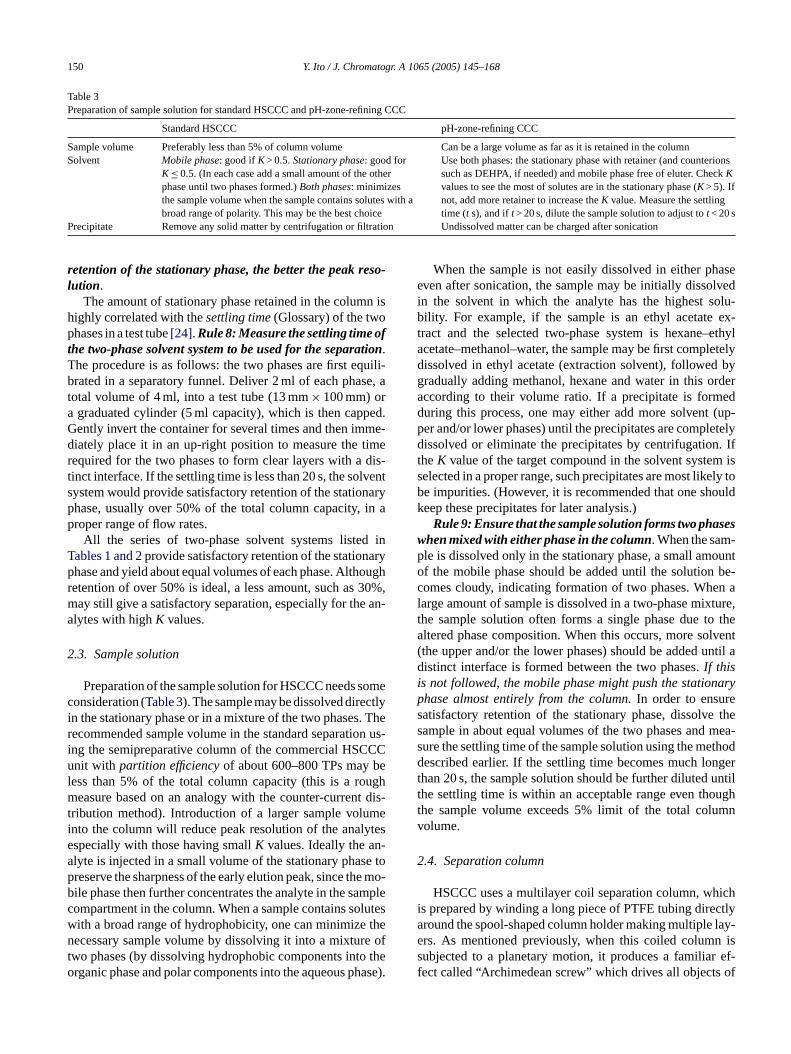
Table 3Preparation of sample solution for standard HSCCC and pH-zone-refining CCC
Standard HSCCC pH-zone-refining CCC
Sample volume Preferably less than 5% of column volume Can be a large volume as far as it is retained in the columnSolvent Mobile phase: good ifK> 0.5.Stationary phase: good for
K≤ 0.5. (In each case add a small amount of the otherphase until two phases formed.)Both phases: minimizesthe sample volume when the sample contains solutes with abroad range of polarity. This may be the best choice
Use both phases: the stationary phase with retainer (and counterionssuch as DEHPA, if needed) and mobile phase free of eluter. CheckKvalues to see the most of solutes are in the stationary phase (K> 5). Ifnot, add more retainer to increase theK value. Measure the settlingtime (t s), and ift> 20 s, dilute the sample solution to adjust tot< 20 s
Precipitate Remove any solid matter by centrifugation or filtration Undissolved matter can be charged after sonication
retention of the stationary phase, the better the peak reso-lution.
The amount of stationary phase retained in the column ishighly correlated with thesettling time(Glossary) of the twophases in a test tube[24].Rule8:Measure thesettling timeofthe two-phase solvent system to be used for the separation.The procedure is as follows: the two phases are first equili-brated in a separatory funnel. Deliver 2 ml of each phase, atotal volume of 4 ml, into a test tube (13 mm× 100 mm) ora graduated cylinder (5 ml capacity), which is then capped.Gently invert the container for several times and then imme-diately place it in an up-right position to measure the timerequired for the two phases to form clear layers with a dis-tinct interface. If the settling time is less than 20 s, the solventsystem would provide satisfactory retention of the stationaryphase, usually over 50% of the total column capacity, in aproper range of flow rates.
All the series of two-phase solvent systems listed inTables 1 and 2provide satisfactory retention of the stationaryphase and yield about equal volumes of each phase. Althoughretention of over 50% is ideal, a less amount, such as 30%,may still give a satisfactory separation, especially for the an-alytes with highK values.
2.3. Sample solution
omec tlyi . Ther n us-i CCu bel ughm t dis-t mei ytese -a e top e mob mplec lutesw then e oft theo hase)
When the sample is not easily dissolved in either phaseeven after sonication, the sample may be initially dissolvedin the solvent in which the analyte has the highest solu-bility. For example, if the sample is an ethyl acetate ex-tract and the selected two-phase system is hexane–ethylacetate–methanol–water, the sample may be first completelydissolved in ethyl acetate (extraction solvent), followed bygradually adding methanol, hexane and water in this orderaccording to their volume ratio. If a precipitate is formedduring this process, one may either add more solvent (up-per and/or lower phases) until the precipitates are completelydissolved or eliminate the precipitates by centrifugation. IftheK value of the target compound in the solvent system isselected in a proper range, such precipitates are most likely tobe impurities. (However, it is recommended that one shouldkeep these precipitates for later analysis.)
Rule9:Ensure that thesamplesolution forms twophaseswhenmixedwith either phase in the column. When the sam-ple is dissolved only in the stationary phase, a small amountof the mobile phase should be added until the solution be-comes cloudy, indicating formation of two phases. When alarge amount of sample is dissolved in a two-phase mixture,the sample solution often forms a single phase due to thealtered phase composition. When this occurs, more solvent(the upper and/or the lower phases) should be added until adi naryp es thes mea-s thodd ngert untilt ought mnv
2
hichi ctlya lay-e n iss r ef-f of
Preparation of the sample solution for HSCCC needs sonsideration (Table 3). The sample may be dissolved direc
n the stationary phase or in a mixture of the two phasesecommended sample volume in the standard separationg the semipreparative column of the commercial HSCnit with partition efficiencyof about 600–800 TPs may
ess than 5% of the total column capacity (this is a roeasure based on an analogy with the counter-curren
ribution method). Introduction of a larger sample volunto the column will reduce peak resolution of the analspecially with those having smallK values. Ideally the anlyte is injected in a small volume of the stationary phasreserve the sharpness of the early elution peak, since thile phase then further concentrates the analyte in the saompartment in the column. When a sample contains soith a broad range of hydrophobicity, one can minimizeecessary sample volume by dissolving it into a mixtur
wo phases (by dissolving hydrophobic components intorganic phase and polar components into the aqueous p
-
.
istinct interface is formed between the two phases.If thiss not followed, the mobile phase might push the statiohase almost entirely from the column.In order to ensuratisfactory retention of the stationary phase, dissolveample in about equal volumes of the two phases andure the settling time of the sample solution using the meescribed earlier. If the settling time becomes much lo
han 20 s, the sample solution should be further dilutedhe settling time is within an acceptable range even thhe sample volume exceeds 5% limit of the total coluolume.
.4. Separation column
HSCCC uses a multilayer coil separation column, ws prepared by winding a long piece of PTFE tubing direround the spool-shaped column holder making multiplers. As mentioned previously, when this coiled columubjected to a planetary motion, it produces a familiaect called “Archimedean screw” which drives all objects
Y. Ito / J. Chromatogr. A 1065 (2005) 145–168 151
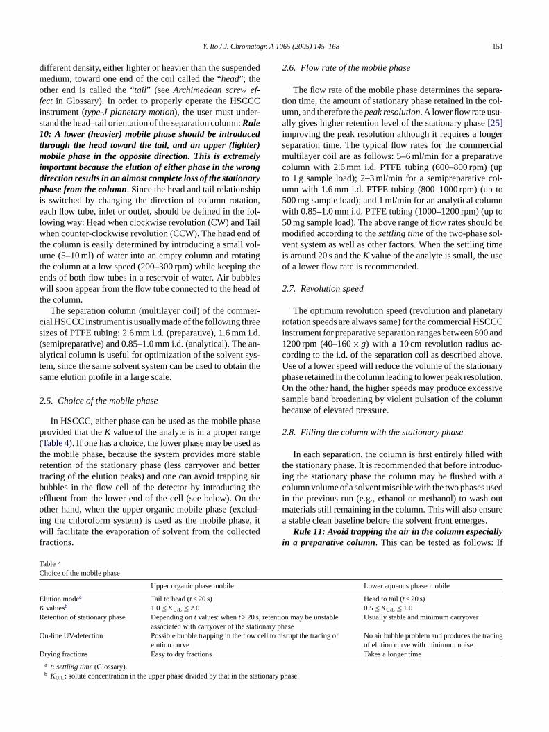
different density, either lighter or heavier than the suspendedmedium, toward one end of the coil called the “head”; theother end is called the “tail” (seeArchimedean screw ef-fect in Glossary). In order to properly operate the HSCCCinstrument (type-J planetary motion), the user must under-stand the head–tail orientation of the separation column:Rule10: A lower (heavier) mobile phase should be introducedthrough the head toward the tail, and an upper (lighter)mobile phase in the opposite direction. This is extremelyimportant because the elution of either phase in the wrongdirection results in an almost complete loss of the stationaryphase from the column. Since the head and tail relationshipis switched by changing the direction of column rotation,each flow tube, inlet or outlet, should be defined in the fol-lowing way: Head when clockwise revolution (CW) and Tailwhen counter-clockwise revolution (CCW). The head end ofthe column is easily determined by introducing a small vol-ume (5–10 ml) of water into an empty column and rotatingthe column at a low speed (200–300 rpm) while keeping theends of both flow tubes in a reservoir of water. Air bubbleswill soon appear from the flow tube connected to the head ofthe column.
The separation column (multilayer coil) of the commer-cial HSCCC instrument is usually made of the following threesizes of PTFE tubing: 2.6 mm i.d. (preparative), 1.6 mm i.d.( an-a ys-t in thes
2
hasep ge( ed ast stabler ettert g airb thee theo clud-i e, itw tedf
2.6. Flow rate of the mobile phase
The flow rate of the mobile phase determines the separa-tion time, the amount of stationary phase retained in the col-umn, and therefore thepeak resolution. A lower flow rate usu-ally gives higher retention level of the stationary phase[25]improving the peak resolution although it requires a longerseparation time. The typical flow rates for the commercialmultilayer coil are as follows: 5–6 ml/min for a preparativecolumn with 2.6 mm i.d. PTFE tubing (600–800 rpm) (upto 1 g sample load); 2–3 ml/min for a semipreparative col-umn with 1.6 mm i.d. PTFE tubing (800–1000 rpm) (up to500 mg sample load); and 1 ml/min for an analytical columnwith 0.85–1.0 mm i.d. PTFE tubing (1000–1200 rpm) (up to50 mg sample load). The above range of flow rates should bemodified according to thesettling timeof the two-phase sol-vent system as well as other factors. When the settling timeis around 20 s and theK value of the analyte is small, the useof a lower flow rate is recommended.
2.7. Revolution speed
The optimum revolution speed (revolution and planetaryrotation speeds are always same) for the commercial HSCCCinstrument for preparative separation ranges between 600 and1 c-c ove.U naryp tion.O essives umnb
2
itht duc-i ith ac sedi outm urea s.
llyi If
TC
EKR , retent
ationarO w cell ing
D
e statio
semipreparative) and 0.85–1.0 mm i.d. (analytical). Thelytical column is useful for optimization of the solvent s
em, since the same solvent system can be used to obtaame elution profile in a large scale.
.5. Choice of the mobile phase
In HSCCC, either phase can be used as the mobile provided that theK value of the analyte is in a proper ranTable 4). If one has a choice, the lower phase may be ushe mobile phase, because the system provides moreetention of the stationary phase (less carryover and bracing of the elution peaks) and one can avoid trappinubbles in the flow cell of the detector by introducingffluent from the lower end of the cell (see below). Onther hand, when the upper organic mobile phase (ex
ng the chloroform system) is used as the mobile phasill facilitate the evaporation of solvent from the collec
ractions.
able 4hoice of the mobile phase
Upper organic phase mobile
lution modea Tail to head (t< 20 s)valuesb 1.0≤KU/L ≤ 2.0etention of stationary phase Depending ont values: whent> 20 s
associated with carryover of the stn-line UV-detection Possible bubble trapping in the flo
elution curverying fractions Easy to dry fractionsa t: settling time(Glossary).b KU/L : solute concentration in the upper phase divided by that in th
200 rpm (40–160×g) with a 10 cm revolution radius aording to the i.d. of the separation coil as described abse of a lower speed will reduce the volume of the statiohase retained in the column leading to lower peak resolun the other hand, the higher speeds may produce exc
ample band broadening by violent pulsation of the colecause of elevated pressure.
.8. Filling the column with the stationary phase
In each separation, the column is first entirely filled whe stationary phase. It is recommended that before introng the stationary phase the column may be flushed wolumn volume of a solvent miscible with the two phases un the previous run (e.g., ethanol or methanol) to wash
aterials still remaining in the column. This will also ensstable clean baseline before the solvent front emergeRule 11: Avoid trapping the air in the column especia
n a preparative column. This can be tested as follows:
Lower aqueous phase mobile
Head to tail (t< 20 s)0.5≤KU/L ≤ 1.0
ion may be unstabley phase
Usually stable and minimum carryover
to disrupt the tracing of No air bubble problem and produces the tracof elution curve with minimum noise
Takes a longer time
nary phase.
152 Y. Ito / J. Chromatogr. A 1065 (2005) 145–168
no air is present in the column, the flow from the columnoutlet is ceased shortly after stopping the pumping. If thesolvent keeps flowing out from the outlet for over severalseconds, the air trapped in the column should be eliminatedby resuming the pumping of the stationary phase under lowspeed column rotation (100–200 rpm) in a tail to head elutionmode to accelerate air movement toward the outlet of thecolumn.
2.9. Sample loading
There are two ways to carry out the procedure. Both aresatisfactory for the HSCCC separation. In the first method,the column is first entirely filled with the stationary phase andthis is immediately followed by sample injection. The mobilephase is then eluted through the column while the column isrotated at the optimum rate. In the second method, after thecolumn is filled with the stationary phase, the mobile phaseis eluted through the column at a desired rate until the solventfront emerges andhydrodynamic equilibriumis establishedthroughout the column as evidenced by diminishedcarryoverof the stationary phase. The sample is then injected into thecolumn through the sample port. Each method has its ownadvantages. It is obvious that the second method will give aclear tracing of the elution curve because of the minimumc firstm rationt mice
plel is ofm thec tiono
2
bec en-t be-t sta-t s todp ngt ther
p oft iono andd n bel oryf bing( n-i iallyi lemb apo-
rative light scattering detection (ELSD) if the mother solventcontains no solid component.
For analytes without chromophores, on-line monitoringof the effluent can be performed by various ways, e.g., us-ing ELSD[26], mass spectrometry (HSCCC–MS)[27] or IR[28]. Although on-line is recommended, it is not necessaryif one has optimized the solvent system so that the targetcompound elutes after a reasonable volume predicated by itsK value. After collecting fractions, one can evaluate themby HPLC or TLC combined with densitometry, although onsome occasions it may be necessary to drying the fractionsand redissolving the residues in an appropriate solvent.
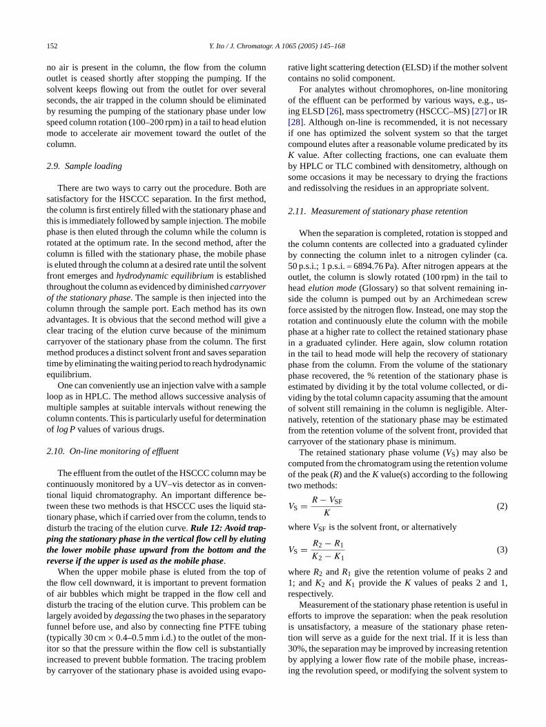
2.11. Measurement of stationary phase retention
When the separation is completed, rotation is stopped andthe column contents are collected into a graduated cylinderby connecting the column inlet to a nitrogen cylinder (ca.50 p.s.i.; 1 p.s.i.= 6894.76 Pa). After nitrogen appears at theoutlet, the column is slowly rotated (100 rpm) in the tail toheadelution mode(Glossary) so that solvent remaining in-side the column is pumped out by an Archimedean screwforce assisted by the nitrogen flow. Instead, one may stop therotation and continuously elute the column with the mobilephase at a higher rate to collect the retained stationary phasei tioni aryp naryp se ise di-v ounto er-n atedf thatc
c lumeo gt
V
w
V
w nd1 1,r
ful ine utioni eten-t an3 ntionb as-i m to
arryover of the stationary phase from the column. Theethod produces a distinct solvent front and saves sepa
ime by eliminating the waiting period to reach hydrodynaquilibrium.
One can conveniently use an injection valve with a samoop as in HPLC. The method allows successive analys
ultiple samples at suitable intervals without renewingolumn contents. This is particularly useful for determinaf logPvalues of various drugs.
.10. On-line monitoring of effluent
The effluent from the outlet of the HSCCC column mayontinuously monitored by a UV–vis detector as in convional liquid chromatography. An important differenceween these two methods is that HSCCC uses the liquidionary phase, which if carried over from the column, tendisturb the tracing of the elution curve.Rule 12: Avoid trap-ing the stationary phase in the vertical flow cell by elutihe lower mobile phase upward from the bottom andeverse if the upper is used as the mobile phase.
When the upper mobile phase is eluted from the tohe flow cell downward, it is important to prevent formatf air bubbles which might be trapped in the flow cellisturb the tracing of the elution curve. This problem ca
argely avoided bydegassingthe two phases in the separatunnel before use, and also by connecting fine PTFE tutypically 30 cm× 0.4–0.5 mm i.d.) to the outlet of the motor so that the pressure within the flow cell is substantncreased to prevent bubble formation. The tracing proby carryover of the stationary phase is avoided using ev
n a graduated cylinder. Here again, slow column rotan the tail to head mode will help the recovery of stationhase from the column. From the volume of the statiohase recovered, the % retention of the stationary phastimated by dividing it by the total volume collected, oriding by the total column capacity assuming that the amf solvent still remaining in the column is negligible. Altatively, retention of the stationary phase may be estim
rom the retention volume of the solvent front, providedarryover of the stationary phase is minimum.
The retained stationary phase volume (VS) may also beomputed from the chromatogram using the retention vof the peak (R) and theK value(s) according to the followin
wo methods:
S = R − VSF
K(2)
hereVSF is the solvent front, or alternatively
S = R2 − R1
K2 − K1(3)
hereR2 andR1 give the retention volume of peaks 2 a; andK2 andK1 provide theK values of peaks 2 andespectively.
Measurement of the stationary phase retention is usefforts to improve the separation: when the peak resol
s unsatisfactory, a measure of the stationary phase rion will serve as a guide for the next trial. If it is less th0%, the separation may be improved by increasing retey applying a lower flow rate of the mobile phase, incre
ng the revolution speed, or modifying the solvent syste
Y. Ito / J. Chromatogr. A 1065 (2005) 145–168 153
shorten thesettling time. If instead the stationary phase re-tention is over 50%, efforts should be directed to search for anew two-phase solvent system, which provides an improvedseparation factor(α) between the analytes.
3. pH-zone-refining counter-currentchromatography
pH-zone-refining CCC[29–33]is generally employed asa large-scale preparative technique for separating ionizableanalytes. The method elutes highly concentrated rectangu-lar peaks fused together with minimum overlapping whileimpurities are concentrated and eluted between the outsidethe major peaks according to their pKa and hydrophobicity.Although it somewhat resembles displacement chromatogra-phy, there are distinct differences between these two methods[30].
The greatest advantage of the method is its large sam-ple loading capacity, which exceeds 10-fold that of the stan-dard HSCCC in the same separation column. In addition, themethod provides various special features such as yieldinghighly concentrated fractions, concentrating minor impuri-ties for detection, and allowing the separation to be monitoredby the pH of the effluent when there are no chromophores.
mplea CCCt
3
ani Tf con-to ft ase int r half
F waysc ak witht
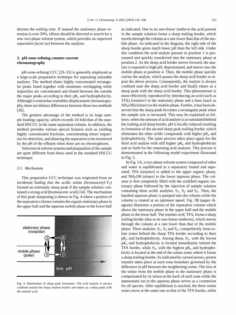
as indicated. Due to itsnon-linear isothermthe acid presentin the sample solution forms a sharp trailing border, whichtravels through the column at a rate lower than that of the mo-bile phase. As indicated in the diagram, the right side of thesharp border gives much lower pH than the left side. Underthis condition the acid analyte present in position 1 is pro-tonated and quickly transferred into the stationary phase atposition 2. As the sharp acid border moves forward, the ana-lyte is exposed to high pH, deprotonated, and moves into themobile phase at position 4. Then, the mobile phase quicklycarries the analyte, which passes the sharp acid border to re-peat the above process. Consequently, the analyte is alwaysconfined near the sharp acid border and finally elutes as asharp peak with the sharp acid border. This phenomenon ismore effectively reproduced by introducing an acid (such asTFA) (retainer) in the stationary phase and a base (such asNH4OH) (eluter) in the mobile phase. Further, it has been ob-served that the sharp peak becomes a rectangular peak whenthe sample size is increased. This may be explained as fol-lows: when the amount of acid analyte is accumulated behindthe trailing acid sharp border, pH is locally reduced resultingin formation of the second sharp peak trailing border, whicheliminates the other acidic compounds with higher pKa andhydrophobicity. The same process takes place again for thethird acid analyte with still higher pKa and hydrophobicitya ss isd tedi
thera epa-r ase,a col-u ta-t tioncb le theca hichs obilep harpt vest bilep -l theirp tp theT -b rmsa otont y thed ss oft se isc le thea terionf lutez while
Selection of solvent systems and preparation of the sare quite different from those used in the standard HS
echnique.
.1. Mechanism
This preparative CCC technique was originated fromncidental finding that the acidic solute (bromoacetyl-3)ormed an extremely sharp peak if the sample solutionained a strong acid (bromoacetic acid)[34]. The mechanismf this peak sharpening is shown inFig. 4where a portion o
he separation column contains the organic stationary phhe upper half and the aqueous mobile phase in the lowe
ig. 4. Mechanism of sharp peak formation. The acid analyte is alonfined around the sharp retainer border and elutes as a sharp pehe retainer acid.
nd so forth for the remaining acid analytes. This proceemonstrated in the following model experiment illustra
n Fig. 5.In Fig. 5A, a two-phase solvent system composed of e
nd water is equilibrated in a separatory funnel and sated. TFA (retainer) is added to the upper organic phnd NH4OH (eluter) to the lower aqueous phase. Themn is first completely filled with the acidified organic s
ionary phase followed by the injection of sample soluontaining three acidic analytes, S1, S2 and S3. Then, theasified aqueous phase is pumped into the column whiolumn is rotated at an optimum speed.Fig. 5B (upper di-gram) illustrates a portion of the separation column whows the stationary phase in the upper half and the mhase in the lower half. The retainer acid, TFA, forms a s
railing border (due to its non-linear isotherm), which mohrough the column at a rate lower than that of the mohase. Three analytes, S1, S2 and S3, competitively form so
ute zones behind the sharp TFA border according toKa and hydrophobicity. Among these, S1, with the lowesKa and hydrophobicity is located immediately behindFA border, while S3, with the highest pKa and hydrophoicity is located at the end of the solute zones where it fosharp trailing border. As indicated by curved arrows, pr
ransfer takes place at each zone boundary governed bifference in pH between the neighboring zones. The lo
he solute from the mobile phase to the stationary phaompensated by its return at the back of each zone whimmonium ion in the aqueous phase serves as a coun
or all species. After equilibrium is reached, the three soones move at the same rate as that of the TFA border,

154 Y. Ito / J. Chromatogr. A 1065 (2005) 145–168
Fig. 5. Model experiment to demonstrate the mechanism of pH-zone-refining CCC. (A) Preparation of the mobile and stationary phases for separa-tion of acid analytes. (B) pH-zone formation of three analytes in the column(upper diagram), and the elution profile of the analytes (lower diagram).
constantly maintaining their width and pH. Charged minorcomponents present in each zone are efficiently eliminatedeither forward or backward according to their partition coef-ficients (pKa and hydrophobicity) and eventually accumulateat the zone boundaries. Consequently, the three analytes eluteas a train of rectangular peaks with sharp impurity peaks attheir narrow boundaries as illustrated inFig. 5B (lower dia-gram).
3.2. Selection of the solvent system for pH-zone-refiningCCC
Solvent systems, which have been successfully used forpH-zone-refining CCC, are described in several monographsand review articles[30–32](seeAppendix B). Since the an-alytes are ionizable compounds, most separations can beperformed using relatively polar solvent systems listed inTable 2. Unless the analytes are hydrophobic compoundssuch as long-chain fatty acids, one can start at a two-phasesolvent system composed of methyltert-butyl ether–waterby following step by step the partition procedures indicatedbelow [30]: Rule 13: For an acidic analyte follow thesesteps:
(1) A 2 ml volume of each phase and 5�l of NH4OH (ca.28% NH3 stock solution) (eluter) is delivered into a test
( cantveral
( d the
( n-the
(ep-
( ureethyl
( ce-
in
a rT
an-a unte-r or-g usingd andc es[ or
tube (13 mm× 100 mm) or bring the pH above 10.2) Add a small amount of the analyte (so that no signifi
change is made in pH), apply a stopper and vortex setimes to equilibrate the contents.
3) Measure the analyte concentration in the upper anlower phases to obtainKU/L value orKbase.
4) If Kbase� 1, add TFA (retainer) (ca. 20 mM) to the cotents to bring the pH to around 2, and reequilibratecontents by vortexing.
5) Using the procedure in Step (3), obtainKacid, and ifKacid� 1, the solvent composition is suitable for saration.
6) If Kbaseis not small enough, repeat the whole procedusing a less polar solvent system such as hexane–acetate–methanol–water, 1:1:1:1 inTable 1and moveupward.
7) If Kacid is not large enough, repeat the whole produre using a more polar solvent system of methyltert-butyl ether (MBE)–acetonitrile (ACN)–water (2:2:3)Table 2and downward.
Rule 14: For a basic analyte, substitute HCl for NH4OHt Step (1) to test Kacid�1, and substitute triethylamine foFA at Step (4) to test Kbase�1.
For zwitterion (free peptides, etc.) or highly polarlytes (catecholamines), the use of a hydrophobic coion is required to retain the analyte in the stationaryanic phase. A successful separation may be performedi(2-ethylhexyl)phosphoric acid (DEHPA) for peptidesatecholamines[30], and dodecylamine for sulfonated dy33]. Forchiral separations[35,36], a suitable chiral select
Y. Ito / J. Chromatogr. A 1065 (2005) 145–168 155
such asN-dodecanoyl-l-proline-3,5-dimethylanilide is dis-solved in the stationary phase: the higher its concentration,the greater the resolution.
All of these selectors are dissolved in the stationary phaseat the optimum concentration determined by the preliminarystudy. One important requirement is that the selector mustbe almost entirely distributed in the stationary phase. Theuse of a selector such as DEHPA requires that the solventpH be kept at neutral or in an acidic range in the columnby eluting with a proper concentration of HCl in the mobilephase to prevent intensive emulsification of the two solventphases.
3.3. Optimization of separation condition
After the solvent composition is determined, the retainer(typical concentration of 10–20 mM) is added to the organicphase and the eluter (about equal molar concentration to theretainer) is added to the aqueous phase. The concentrationof eluter in the mobile phase mainly determines the concen-tration of analyte in the eluted fractions. Therefore, increas-ing the eluter concentration results in a higher concentrationand shorter retention time of the analyte. On the other hand,the concentration of the retainer in the stationary phase de-termines the concentration of analyte in the stationary phasew con-c tion-a asedK
ivelys inera h re-t naryp e duet int -c
mo-b r andv ouss d anal ase.T difiest eas-i andi anicp ainerm
3
ingC epa-r rcials citym the
sample in the solvent system (which is about 10 times thatused for the standard HSCCC separation). The sample solu-tion is prepared by dissolving a desired amount of sample inthe stationary phase containing the retainer (and hydropho-bic counterion or chiral selector) and adding a lesser amountof the mobile phase free of eluter. Although it is ideal tocompletely dissolve the sample, a sample solution containingundissolved solute may be introduced into the column aftermaking a fine homogeneous suspension by sonicating for sev-eral minutes. Alternatively, the precipitates may be removedby centrifugation for later analysis. In pH-zone-refining CCC,the analyte concentration in the mobile phase is largely de-termined by the molar concentration of the eluter (counteri-ons). Therefore, the analyte concentration in the eluted frac-tions is irrelevant to the initial concentration in the samplesolution.
Application of highly concentrated solutions tends tomodify the solvent composition and interfacial tension, whichmay lead to a loss of the stationary phase from the column.Rule16: If the settling timeof the sample solution is lengthy,further dilution of the sample is recommended. Our experi-ments have shown that the sample volume can be as large as200 ml for a separation column of 320 ml capacity, providedthat retention of the stationary phase is over 70%.
In the sample solution consisting of two phases, the targeta tion-a thes salt),w oc-c bringtm t tot
3
elyw idi-fi bya n them lumnw ually8 UVd le)[ ctor.I allym te-d thati ointi
, isu y re-s rion,wa o-b d
ithin the column. Consequently, increasing the retainerentration raises the concentration of analytes in the stary phase associated with a longer retention time or increvalue of the analyte.In general, a large amount of sample can be effect
eparated by applying high concentrations of both retand eluter, e.g., 40 mM each. However, use of such hig
ainer concentration often induces carryover of the statiohase, apparently caused by precipitation of the analyt
o its excessively high concentration or limited solubilityhe stationary phase.Rule 15: Start with equal molar conentrations of retainer and eluter such as 10–20mM each.
The method allows the use of an organic phase as theile phase (in this case, the retainer becomes the eluteice versa)[30]. In this operation, the retainer in the aquetationary phase serves as the counterion for the retaineytes to determine their concentration in the stationary phhe eluter in the organic phase, on the other hand, mo
he partition coefficient of analytes in such a way that incrng the eluter concentration shortens the retention timencreases the concentration of analyte in the mobile orghase. In this mode, 10–20 mM each of the eluter and retay also produce a satisfactory result.
.4. Sample solution
The preparation of sample solution for pH-zone-refinCC is different from that used in the standard HSCCC s
ation. A typical sample size to be separated by a commeemipreparative HSCCC unit with a 320 ml column capaay range from 0.5 to 5 g depending on the solubility of
-
nalyte should be almost entirely distributed into the stary phase. If this is not the case, it is most likely thatample contains a large amount of salt (such as sodiumhich alters the pH of the sample solution. If this pH shifturs, retainer should be added to the sample solution tohe pH into a proper range. Therefore,Rule 17: Routinelyeasure the pH of the sample solution before applying ihe column.
.5. Separation procedure
The separation is initiated by filling the column entirith the stationary phase, which is previously either aced or basified according to the analyte. This is followeddding the sample solution through the sample port. Theobile phase containing the eluter is pumped into the cohile the apparatus is rotated at an optimum speed (us00 rpm). The effluent is continuously monitored usingetection followed by on-line pH monitoring (if availab
37] and collected into test tubes using a fraction collef an on-line pH monitor is not available, one can manueasure the pH of the collected fractions. Although it isious, this manual pH determination has an advantage
t facilitates accurately locating the sharp pH transition pn the collected fractions.
When the hydrophobic counterion, such as DEHPAsed in the stationary phase, the above operation mault in a steady leakage of a small amount of the countehich contaminates the collected fractions.Rule 18: Leavesmall amount of the stationary phase free of hydrophic counterions at the end of the column. This is achieve
156 Y. Ito / J. Chromatogr. A 1065 (2005) 145–168
by partially filling the column with a stationary phase (freeof DEHPA but containing the retainer) followed by pump-ing a measured volume of the stationary phase containingDEHPA. In this way the counterion-free stationary phase re-tained at the end portion of the column serves as an absorbentfor DEHPA.
4. Conclusion
The author hopes that the instructions and advices pre-sented above will be useful and encourage others interestedin separations to use this technique which he feels, with
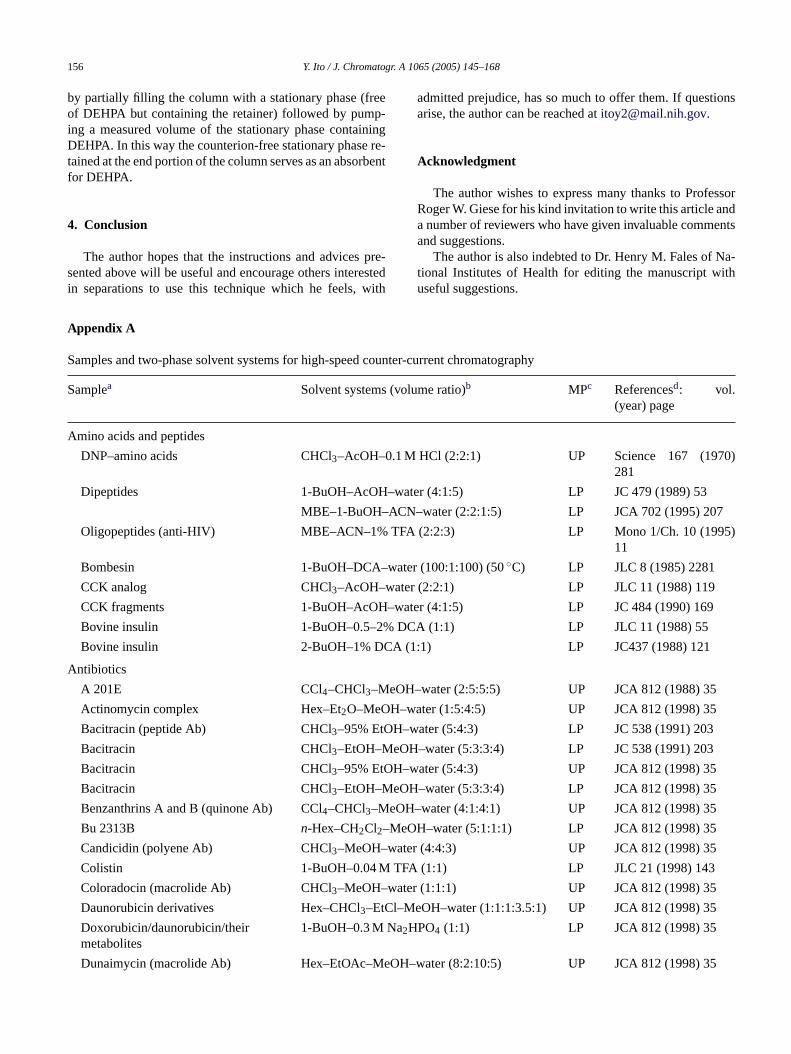
Appendix A
Samples and two-phase solvent systems for high-speed counter-current chromatography
Samplea Solvent systems (volume ratio)b MPc Referencesd: vol.(year) page
Amino acids and peptides
DNP–amino acids CHCl3–AcOH–0.1 M HCl (2:2:1) UP Science 167 (1970)281
Dipeptides 1-BuOH–AcOH–water (4:1:5) LP JC 479 (1989) 53
ACN 7
% TFA 95)
–wate
water
H–wa
2% D
CA (
eOH–
H–water (1:5:4:5) UP JCA 812 (1998) 35
OH–water (5:4:3) LP JC 538 (1991) 203
admitted prejudice, has so much to offer them. If questionsarise, the author can be reached [email protected].
Acknowledgment
The author wishes to express many thanks to ProfessorRoger W. Giese for his kind invitation to write this article anda number of reviewers who have given invaluable commentsand suggestions.
The author is also indebted to Dr. Henry M. Fales of Na-tional Institutes of Health for editing the manuscript withuseful suggestions.
MBE–1-BuOH–
Oligopeptides (anti-HIV) MBE–ACN–1
Bombesin 1-BuOH–DCA
CCK analog CHCl3–AcOH–
CCK fragments 1-BuOH–AcO
Bovine insulin 1-BuOH–0.5–
Bovine insulin 2-BuOH–1% D
Antibiotics
A 201E CCl4–CHCl3–M
Actinomycin complex Hex–Et2O–MeO
Bacitracin (peptide Ab) CHCl3–95% Et
Bacitracin CHCl3–EtOH–MeOH
Bacitracin CHCl3–95% EtOH–w
Bacitracin CHCl3–EtOH–MeOH
Benzanthrins A and B (quinone Ab) CCl4–CHCl3–MeOH–
Bu 2313B n-Hex–CH2Cl2–MeO
Candicidin (polyene Ab) CHCl3–MeOH–wate
Colistin 1-BuOH–0.04 M TFA
Coloradocin (macrolide Ab) CHCl3–MeOH–wate
Daunorubicin derivatives Hex–CHCl3–EtCl–Me
Doxorubicin/daunorubicin/theirmetabolites
1-BuOH–0.3 M Na2H
Dunaimycin (macrolide Ab) Hex–EtOAc–MeOH
–water (2:2:1:5) LP JCA 702 (1995) 20
(2:2:3) LP Mono 1/Ch. 10 (1911
r (100:1:100) (50◦C) LP JLC 8 (1985) 2281
(2:2:1) LP JLC 11 (1988) 119
ter (4:1:5) LP JC 484 (1990) 169
CA (1:1) LP JLC 11 (1988) 55
1:1) LP JC437 (1988) 121
water (2:5:5:5) UP JCA 812 (1988) 35
–water (5:3:3:4) LP JC 538 (1991) 203
ater (5:4:3) UP JCA 812 (1998) 35
–water (5:3:3:4) LP JCA 812 (1998) 35
water (4:1:4:1) UP JCA 812 (1998) 35
H–water (5:1:1:1) LP JCA 812 (1998) 35
r (4:4:3) UP JCA 812 (1998) 35
(1:1) LP JLC 21 (1998) 143
r (1:1:1) UP JCA 812 (1998) 35
OH–water (1:1:1:3.5:1) UP JCA 812 (1998) 35
PO4 (1:1) LP JCA 812 (1998) 35
–water (8:2:10:5) UP JCA 812 (1998) 35
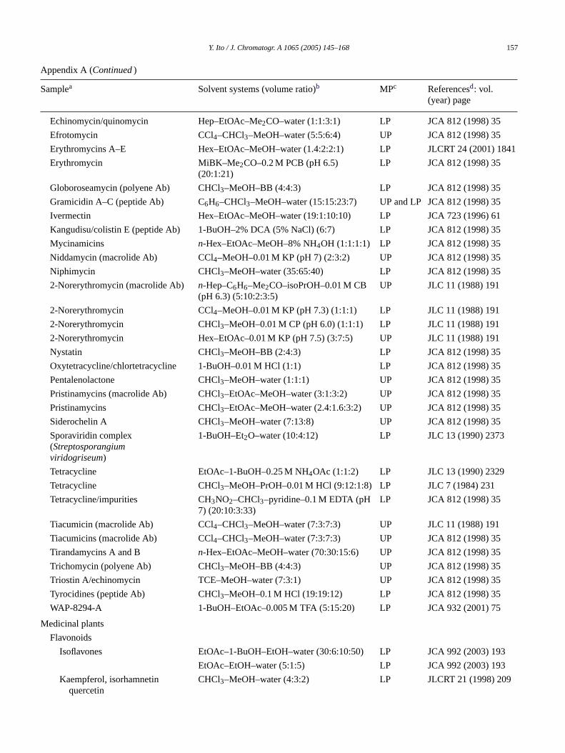
Y. Ito / J. Chromatogr. A 1065 (2005) 145–168 157
Appendix A (Continued)
Samplea Solvent systems (volume ratio)b MPc Referencesd: vol.(year) page
Echinomycin/quinomycin Hep–EtOAc–Me2CO–water (1:1:3:1) LP JCA 812 (1998) 35
Efrotomycin CCl4–CHCl3–MeOH–water (5:5:6:4) UP JCA 812 (1998) 35
Erythromycins A–E Hex–EtOAc–MeOH–water (1.4:2:2:1) LP JLCRT 24 (2001) 1841
Erythromycin MiBK–Me2CO–0.2 M PCB (pH 6.5)(20:1:21)
LP JCA 812 (1998) 35
Globoroseamycin (polyene Ab) CHCl3–MeOH–BB (4:4:3) LP JCA 812 (1998) 35
Gramicidin A–C (peptide Ab) C6H6–CHCl3–MeOH–water (15:15:23:7) UP and LP JCA 812 (1998) 35
Ivermectin Hex–EtOAc–MeOH–water (19:1:10:10) LP JCA 723 (1996) 61
Kangudisu/colistin E (peptide Ab) 1-BuOH–2% DCA (5% NaCl) (6:7) LP JCA 812 (1998) 35
Mycinamicins n-Hex–EtOAc–MeOH–8% NH4OH (1:1:1:1) LP JCA 812 (1998) 35
Niddamycin (macrolide Ab) CCl4–MeOH–0.01 M KP (pH 7) (2:3:2) UP JCA 812 (1998) 35
Niphimycin CHCl3–MeOH–water (35:65:40) LP JCA 812 (1998) 35
2-Norerythromycin (macrolide Ab) n-Hep–C6H6–Me2CO–isoPrOH–0.01 M CB(pH 6.3) (5:10:2:3:5)
UP JLC 11 (1988) 191
2-Norerythromycin CCl4–MeOH–0.01 M KP (pH 7.3) (1:1:1) LP JLC 11 (1988) 191
2-Norerythromycin CHCl3–MeOH–0.01 M CP (pH 6.0) (1:1:1) LP JLC 11 (1988) 191
2-Norerythromycin Hex–EtOAc–0.01 M KP (pH 7.5) (3:7:5) UP JLC 11 (1988) 191
Nystatin CHCl3–MeOH–BB (2:4:3) LP JCA 812 (1998) 35
Oxytetracycline/chlortetracycline 1-BuOH–0.01 M HCl (1:1) LP JCA 812 (1998) 35
Pentalenolactone CHCl3–MeOH–water (1:1:1) UP JCA 812 (1998) 35
Pristinamycins (macrolide Ab) CHCl3–EtOAc–MeOH–water (3:1:3:2) UP JCA 812 (1998) 35
Pristinamycins CHCl3–EtOAc–MeOH–water (2.4:1.6:3:2) UP JCA 812 (1998) 35
Siderochelin A CHCl3–MeOH–water (7:13:8) UP JCA 812 (1998) 35
Sporaviridin complex(Streptosporangiumviridogriseum)
1-BuOH–Et2O–water (10:4:12) LP JLC 13 (1990) 2373
Tetracycline EtOAc–1-BuOH–0.25 M NH4OAc (1:1:2) LP JLC 13 (1990) 2329
Tetracycline CHCl3–MeOH–PrOH–0.01 M HCl (9:12:1:8) LP JLC 7 (1984) 231
Tetracycline/impurities CH3NO2–CHCl3–pyridine–0.1 M EDTA (pH7) (20:10:3:33)
LP JCA 812 (1998) 35
Tiacumicin (macrolide Ab) CCl4–CHCl3–MeOH–water (7:3:7:3) UP JLC 11 (1988) 191
Tiacumicins (macrolide Ab) CCl4–CHCl3–MeOH–water (7:3:7:3) UP JCA 812 (1998) 35
Tirandamycins A and B n-Hex–EtOAc–MeOH–water (70:30:15:6) UP JCA 812 (1998) 35
Trichomycin (polyene Ab) CHCl3–MeOH–BB (4:4:3) UP JCA 812 (1998) 35
Triostin A/echinomycin TCE–MeOH–water (7:3:1) UP JCA 812 (1998) 35
Tyrocidines (peptide Ab) CHCl3–MeOH–0.1 M HCl (19:19:12) LP JCA 812 (1998) 35
WAP-8294-A 1-BuOH–EtOAc–0.005 M TFA (5:15:20) LP JCA 932 (2001) 75
Medicinal plants
Flavonoids
Isoflavones EtOAc–1-BuOH–EtOH–water (30:6:10:50) LP JCA 992 (2003) 193
EtOAc–EtOH–water (5:1:5) LP JCA 992 (2003) 193
Kaempferol, isorhamnetinquercetin
CHCl3–MeOH–water (4:3:2) LP JLCRT 21 (1998) 209
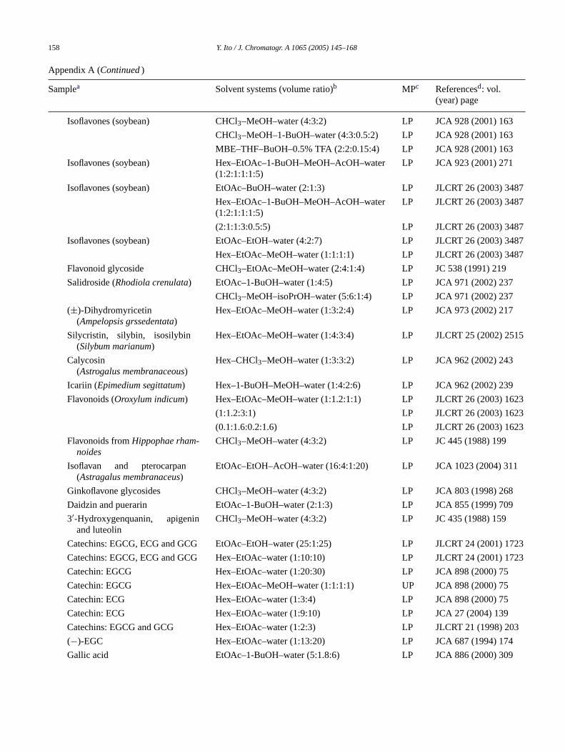
158 Y. Ito / J. Chromatogr. A 1065 (2005) 145–168
Appendix A (Continued)
Samplea Solvent systems (volume ratio)b MPc Referencesd: vol.(year) page
Isoflavones (soybean) CHCl3–MeOH–water (4:3:2) LP JCA 928 (2001) 163
CHCl3–MeOH–1-BuOH–water (4:3:0.5:2) LP JCA 928 (2001) 163
MBE–THF–BuOH–0.5% TFA (2:2:0.15:4) LP JCA 928 (2001) 163
Isoflavones (soybean) Hex–EtOAc–1-BuOH–MeOH–AcOH–water(1:2:1:1:1:5)
LP JCA 923 (2001) 271
Isoflavones (soybean) EtOAc–BuOH–water (2:1:3) LP JLCRT 26 (2003) 3487
Hex–EtOAc–1-BuOH–MeOH–AcOH–water(1:2:1:1:1:5)
LP JLCRT 26 (2003) 3487
(2:1:1:3:0.5:5) LP JLCRT 26 (2003) 3487
Isoflavones (soybean) EtOAc–EtOH–water (4:2:7) LP JLCRT 26 (2003) 3487
Hex–EtOAc–MeOH–water (1:1:1:1) LP JLCRT 26 (2003) 3487
Flavonoid glycoside CHCl3–EtOAc–MeOH–water (2:4:1:4) LP JC 538 (1991) 219
Salidroside (Rhodiola crenulata) EtOAc–1-BuOH–water (1:4:5) LP JCA 971 (2002) 237
CHCl3–MeOH–isoPrOH–water (5:6:1:4) LP JCA 971 (2002) 237
(±)-Dihydromyricetin(Ampelopsis grssedentata)
Hex–EtOAc–MeOH–water (1:3:2:4) LP JCA 973 (2002) 217
Silycristin, silybin, isosilybin(Silybum marianum)
Hex–EtOAc–MeOH–water (1:4:3:4) LP JLCRT 25 (2002) 2515
Calycosin(Astrogalus membranaceous)
Hex–CHCl3–MeOH–water (1:3:3:2) LP JCA 962 (2002) 243
Icariin (Epimedium segittatum) Hex–1-BuOH–MeOH–water (1:4:2:6) LP JCA 962 (2002) 239
Flavonoids (Oroxylum indicum) Hex–EtOAc–MeOH–water (1:1.2:1:1) LP JLCRT 26 (2003) 1623
(1:1.2:3:1) LP JLCRT 26 (2003) 1623
(0.1:1.6:0.2:1.6) LP JLCRT 26 (2003) 1623
Flavonoids fromHippophae rham-noides
CHCl3–MeOH–water (4:3:2) LP JC 445 (1988) 199
Isoflavan and pterocarpan(Astragalus membranaceus)
EtOAc–EtOH–AcOH–water (16:4:1:20) LP JCA 1023 (2004) 311
Ginkoflavone glycosides CHCl3–MeOH–water (4:3:2) LP JCA 803 (1998) 268
Daidzin and puerarin EtOAc–1-BuOH–water (2:1:3) LP JCA 855 (1999) 709
3′-Hydroxygenquanin, apigeninand luteolin
CHCl3–MeOH–water (4:3:2) LP JC 435 (1988) 159
Catechins: EGCG, ECG and GCG EtOAc–EtOH–water (25:1:25) LP JLCRT 24 (2001) 1723
Catechins: EGCG, ECG and GCG Hex–EtOAc–water (1:10:10) LP JLCRT 24 (2001) 1723
Catechin: EGCG Hex–EtOAc–water (1:20:30) LP JCA 898 (2000) 75
Catechin: EGCG Hex–EtOAc–MeOH–water (1:1:1:1) UP JCA 898 (2000) 75
Catechin: ECG Hex–EtOAc–water (1:3:4) LP JCA 898 (2000) 75
Catechin: ECG Hex–EtOAc–water (1:9:10) LP JCA 27 (2004) 139
Catechins: EGCG and GCG Hex–EtOAc–water (1:2:3) LP JLCRT 21 (1998) 203
(−)-EGC Hex–EtOAc–water (1:13:20) LP JCA 687 (1994) 174
Gallic acid EtOAc–1-BuOH–water (5:1.8:6) LP JCA 886 (2000) 309
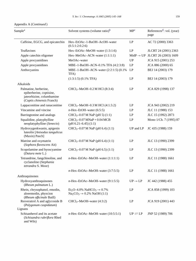
Y. Ito / J. Chromatogr. A 1065 (2005) 145–168 159
Appendix A (Continued)
Samplea Solvent systems (volume ratio)b MPc Referencesd: vol. (year)page
Caffeine, EGCG, and epicatechin Hex–EtOAc–1-BuOH–AcOH–water(0.5:1:2:0.2:6)
LP AC 72 (2000) 3363
Teaflavines Hex–EtOAc–MeOH–water (1:3:1:6) LP JLCRT 24 (2001) 2363
Apple catechin oligomer Hex–MeOAc–ACN–water (1:1:1:1) MidP→ UP JLCRT 26 (2003) 1609
Apple procyanidines MeOAc–water UP JCA 915 (2001) 253
Apple procyanidines MBE–1-BuOH–ACN–0.1% TFA (4:2:3:8) LP JCA 886 (2000) 65
Anthocyanins MBE–1-BuOH–ACN–water (2:2:1:5) (0.1%TFA)
LP BEJ 14 (2003) 179
(1:3:1:5) (0.1% TFA) LP BEJ 14 (2003) 179
Alkaloids
Palmatine, berberine,epiberberine, coptisine,jateorhizine, columbamine(Coptis chinensisFranch)
CHCl3–MeOH–0.2 M HCl (8:3:4) LP JCA 829 (1998) 137
Lappaconitine and ranaconitine CHCl3–MeOH–0.3 M HCl (4:1.5:2) LP JCA 943 (2002) 219
Vincamine and vincine n-Hex–EtOH–water (6:5:5) LP JLC 11 (1988) 153
Barringtonine and analogs CHCl3–0.07 M NaP (pH 5) (1:1) LP JLC 15 (1992) 2873
Squalidine, platyphyllineneoplatyphylline (Senecio)
CHCl3–0.07 MNaP + 0.04 MCB(pH 6.21–6.45) (1:1)
LP Mono 1/Ch. 7 (1995) 87
Hydroxygenkwanin, apigeninluteolin [Anisodus tangulicus(Maxin) Pasch]
CHCl3–0.07 M NaP (pH 6.4) (1:1) UP and LP JC 435 (1988) 159
Matrine and oxymatrin(Sophora flavescensAit)
CHCl3–0.07 M NaP (pH 6.4) (1:1) LP JLC 13 (1990) 2399
Scopolamine and hyoscyamine(Datura meteL.)
CHCl3–0.07 M NaP (pH 6.5) (1:1) LP JLC 13 (1990) 2399
Tetrandrine, fangchinoline, andcyclanoline (StephaniatetrandraS. Moor)
n-Hex–EtOAc–MeOH–water (1:1:1:1) LP JLC 11 (1988) 1661
n-Hex–EtOAc–MeOH–water (3:7:5:5) LP JLC 11 (1988) 1661
Anthraquinones
Hydroxyanthraquinones(Rheum palmatumL.)
n-Hex–EtOAc–MeOH–water (9:1:5:5) UP→ LP JC 442 (1988) 455
Rhein, chrysophanol, emodin,aloeemodin, physcion(Rheum officinaleBaill)
Et2O–4.0% NaHCO3 → 0.7%Na2CO3 → 0.2% NaOH (1:1)
LP JCA 858 (1999) 103
Resveratrol A and aglycoside B(Polygonum cuspidatum)
CHCl3–MeOH–water (4:3:2) LP JCA 919 (2001) 443
Lignans
Schisanherol and its acetate(Schisandra rubrifloraRhedand Wils)
n-Hex–EtOAc–MeOH–water (10:5:5:1) UP� LP JNP 52 (1989) 706

160 Y. Ito / J. Chromatogr. A 1065 (2005) 145–168
Appendix A (Continued)
Samplea Solvent systems (volume ratio)b MPc Referencesd: vol. (year)page
Anti-HIV lignans(Larria tridentata)
Hex–EtOAc–MeOH–0.5% NaCl (7:3:5:5) UP JCA 719 (1996) 353
(7:3:5:5) UP JCA 719 (1996) 353
Hex–CHCl3–MeOH–1.2% NaCl (1:4:4:2) LP JCA 719 (1996) 353
Rhein (Rheum officinaleBaill) n-Hex–EtOAc–MeOH–water (3:7:5:5) LP JCA 1017 (2003) 125
Steroids
25-Hydroxycholecalciferol Hex–EtOAc–MeOH–water (5:1:5:1) LP JLC 18 (1995) 181
Przewaquinone A(Salvia miltiorrhiza)
Hex–CCl4–MeOH–water (1:3:3:2) LP JLCRT 26 (2003) 1267
Cucurbitacin B and E(Cucumis melL.)
Hex–EtOAc–MeOH–water (12:24:16:9) UP Mono 1/Ch. 9 (1995) 107
Quadri-terpenic acids(Ligustrum lucidum)
Hex–EtOAc–MeOH–water (3:6:2:1) LP JLC 18 (1995) 1997
Triterpenoic acid(Boswellia carterii)
n-Hex–EtOH–water (6:5:2) LP JLC 13 (1990) 2389
Steroid alcohols(Tieghemella heckelli)
MBE–1-BuOH–ACN–0.5% TFA (1:3:3:4) LP JLCRT 25 (2002) 2871
Saponins
Dammarane-saponins(Panax notoginseng)
CHCl3–MeOH–2-BuOH–water (5:6:1:4) LP JLCRT 26 (2003) 1579
EtOAc–1-BuOH–water (1:1:2) LP JLCRT 26 (2003) 1579
Arganines and tieghemelin(Tieghemella heckelli)
MBE–1-BuOH–ACN–0.5% TFA (1:3:1:5) LP JLCRT 26 (2002) 3197
Miscellaneous
Taxol and cephalomannine Hex–EtOAc–MeOH–water (6:4:5:5) LP JLCRT 21 (1998) 157
10-Deacetylbaccatin III Hex–EtOAc–EtOH–water (2:5:2:5) LP JCA 813 (1998) 397
Artemisinin, artemisitene andarteannuin B
Hex–EtOAc–EtOH–water (8:2:5:4) LP JLCRT 23 (2000) 909
Hex–EtOAc–EtOH–water (6:4:5:4) LP JLCRT 23 (2000) 909
Notopterol and isoimperatorin LtPet–EtOAc–MeOH–water (5:5:5:4) LP JCA 883 (2000) 67
LtPet–EtOAc–MeOH–water (5:5:4.8:5) LP JCA 883 (2000) 67
Stilbene glycoside(Poligonum multiflorum)
EtOAc–EtOH–water (50:1:50) LP JLCRT 21 (1998) 2897
Acteoside and 2′-acetylacteoside(Cistanches salsa)
EtOAc–1-BuOH–EtOH–water (20:3:3:25) LP JCA 912 (2001) 181
Acteoside and isoacteoside EtOAc–1-BuOH–EtOH–water (35:6:6:50) LP JLCRT 24 (2001) 2127
EtOAc–1-BuOH–EtOH–water (30:10:6:50) LP JLCRT 24 (2001) 2127
Mevinolinic acid(Monascus purpureus)
n-Hex–EtOAc–MeOH–water (1:1:1:1) LP JLCRT 26 (2003) 3083
Taxol and cephalomannine n-Hex–EtOAc–MeOH–water (6:3:5:5) LP JLCRT 21 (1998) 157
Strychnine(Strychnos nux-vomicaL.)
CHCl3–0.07 M NaP (pH 5.08) (1:1) LP JLCRT 21 (1998) 157
Tripdiolides(Tripterygium wilfordii)
Hex–CH2Cl2–MeOH–water (3:22:17:8) LP JLCRT, in press
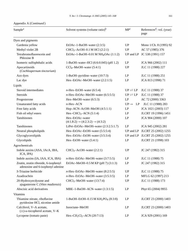
Y. Ito / J. Chromatogr. A 1065 (2005) 145–168 161
Appendix A (Continued)
Samplea Solvent systems (volume ratio)b MPc Referencesd: vol. (year)page
Dyes and pigments
Gardenia yellow EtOAc–1-BuOH–water (2:3:5) UP Mono 1/Ch. 8 (1995) 92
Methyl violet 2B CHCl3–AcOH–0.1 M HCl (2:2:1) UP AC 57 (1985) 376
Tetrabromofluorescein andPhloxine B
EtOAc–1-BuOH–0.01 M NH4OAc (1:1:2) UP and LP JC 538 (1991) 157
Isomeric sulfophthalic acids 1-BuOH–water–HCl (6:6:0.045) (pH 1.2) LP JCA 966 (2002) 111
Apocartinoids(Cochlospernum tinctorium)
CCl4–MeOH–water (5:4:1) UP JLC 11 (1988) 227
Azo dyes 1-BuOH–pyridine–water (10:7:3) LP JLC 11 (1988) 251
Lac dye Hex–EtOAc–MeOH–water (2:2:1:5) LP JCA 813 (1998) 71
Lipids
Steroid intermediates n-Hex–EtOH–water (6:5:4) UP� LP JLC 11 (1988) 37
Steroids n-Hex–EtOAc–MeOH–water (6:5:5:5) UP� LP JLC 11 (1988) 37
Progesterone Hex–MeOH–water (6:5:3) LP AC 72 (2000) 3363
Unsaturated fatty acids n-Hex–ACN UP→ LP JLC 11 (1988) 283
Free fatty acids Hep–ACN–AcOH–MeOH (4:5:1:1) LP JCA 1021 (2003) 117
Fish oil ethyl esters Hex–CHCl3–ACN (5:1:4) LP JLCRT 19 (1996) 1451
Tanshinones Hex–EtOAc–water(4:1.8:2)→ (4:2.3:2)→ (4:3:2)
LP JCA 904 (2000) 107
Tanshinones LtPet–EtOAc–MeOH–water (2:3:2.5:1.7) LP JCA 945 (2002) 281
Neutral phospholipids Hex–EtOAc–EtOH–water (5:5:5:4) UP and LP JLCRT 25 (2002) 1255
Glycoglycerolipids Hex–EtOAc–EtOH–water (3:5:3:4) UP and LP JLCRT 25 (2002) 1255
Glycolipids Hex–EtOH–water (5:4:1) LP JLCRT 21 (1998) 103
Agrochemicals
Indole auxins (ASA, IAcA, IBA,ICA, IPA)
CHCl3–AcOH–water (2:2:1) UP JC 247 (1982) 315
Indole auxins (IA, IAA, ICA, IBA) n-Hex–EtOAc–MeOH–water (3:7:5:5) LP JLC 11 (1988) 75
Zeatin, zeatin riboside, 6-isophenyladenosine and 6-isophenyl adenine
EtOAc–MeOH–0.5 M KP (pH 7) (3:1:3) LP JC 247 (1982) 315
S-Triazine herbicide n-Hex–EtOAc–MeOH–water (8:2:5:5) UP JLC 11 (1988) 75
Azadirachtin n-Hex–EtOAc–MeOH–water (3:5:3:5) LP MFLG 62 (1997) 213
20-Hydroxyecdysone andajugasterone C (Vitex madiensis)
CHCl3–MeOH–water (13:7:4) UP JLC 11 (1988) 173
Abscisic acid derivatives MBE–1-BuOH–ACN–water (1:3:1:5) LP Phyt 65 (2004) 9955
Vitamins
Thiamine nitrate, riboflavinepyridoxine HCl, nicotine amide
1-BuOH–EtOH–0.15 M KH2PO4 (8:3:8) LP JLCRT 23 (2000) 1403
Calciferol, V–A acetate,(±)-�-tocopherol acetate, V–K
Isooctane–MeOH LP JLCRT 23 (2000) 1403
Lycopene (tomato paste) Hex–CH2Cl2–ACN (20:7:13) LP JCA 929 (2001) 169
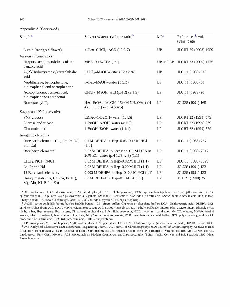
162 Y. Ito / J. Chromatogr. A 1065 (2005) 145–168
Appendix A (Continued)
Samplea Solvent systems (volume ratio)b MPc Referencesd: vol.(year) page
Lutein (marigold flower) n-Hex–CHCl3–ACN (10:3:7) UP JLCRT 26 (2003) 1659
Various organic acids
Hippuric acid, mandelic acid andbenzoic acid
MBE–0.1% TFA (1:1) UP and LP JLCRT 23 (2000) 1575
2-(2′-Hydroxyethoxy) terephthalicacid
CHCl3–MeOH–water (37:37:26) UP JLC 11 (1988) 245
Naphthalene, benzophenone,o-nitrophenol and acetophenone
n-Hex–MeOH–water (3:3:2) LP JLC 11 (1988) 91
Acetophenone, benzoic acid,p-nitrophenone and phenol
CHCl3–MeOH–HCl (pH 2) (3:1:3) LP JLC 11 (1988) 91
Bromoacetyl-T3 Hex–EtOAc–MeOH–15 mM NH4OAc (pH4) (1:1:1:1) and (4:5:4:5)
LP JC 538 (1991) 165
Sugars and PNP derivatives
PNP glucose EtOAc–1-BuOH–water (1:4:5) LP JLCRT 22 (1999) 579
Sucrose and fucose 1-BuOH–AcOH–water (4:1:5) LP JLCRT 22 (1999) 579
Glucronic acid 1-BuOH–EtOH–water (4:1:4) LP JLCRT 22 (1999) 579
Inorganic elements
Rare earth elements (La, Ce, Pr, Nd,Sm, Eu)
0.1 M DEHPA in Hep–0.03–0.15 M HCl(1:1)
LP JLC 11 (1988) 267
Rare earth elements 0.02 M DEHPA in kerosene–0.1 M DCA in20% EG–water (pH 1.35–2.5) (1:1)
LP JLC 11 (1988) 2517
LaCl3, PrCl3, NdCl3 0.02 M DEHPA in Hep–0.02 M HCl (1:1) LP JLC 13 (1990) 2329
La, Pr and Nd 0.02 M DEHPA in Hep–0.02 M HCl (1:1) LP JC 538 (1991) 133
12 Rare earth elements 0.003 M DEHPA in Hep–0–0.3 M HCl (1:1) LP JC 538 (1991) 133
Heavy metals (Ca, Cd, Co, Fe(III),Mg, Mn, Ni, P, Pb, Zn)
0.6 M DEHPA in Hep–0.1 M TA (1:1) LP JCA 21 (1998) 251
a Ab: antibiotics; ABC: abscisic acid; DNP: dinitrophenyl; CCK: cholecystokinin; ECG: epicatechin-3-gallate; EGC: epigallocatechin; EGCG:epigallocatechin-3-O-gallate; GCG: gallocatechin-3-O-gallate; IA: indole-3-acetamide; IAA: indole-3-acetic acid; IAcA: indole-3-acrylic acid; IBA: indole-3-butyric acid; ICA: indole-3-carboxylic acid; T3: 3,3′,5-triiodo-l-thyronine; PNP:p-nitrophenyl.
b AcOH: acetic acid; BB: borate buffer; BuOH: butanol; CB: citrate buffer; CP; citrate + phosphate buffer; DCA: dichloroacetic acid; DEHPA: di(2-ethylhexyl)phosphoric acid; EDTA: ethylenediaminetetraacetic acid; EG: ethylene glycol; EtCl: ethylenechloride, EtOAc: ethyl acetate; EtOH: ethanol; Et2O:diethyl ether; Hep: heptane; Hex: hexane; KP: potassium phosphate; LtPet: light petroleum; MBE: methyltert-butyl ether; Me2CO: acetone; MeOAc: methylacetate; MeOH: methanol; NaP: sodium phosphate; NH4OAc: ammonium acetate; PCB: phosphate + citric acid buffer; PEG: polyethylene glycol; PrOH:propanol; TA: tartaric acid; TFA: trifluoroacetic acid; THF: tetrahydrofuran.
c LP: lower phase; MP: mobile phase; MidP: middle phase; UP: upper phase; UP→ LP: UP followed by LP (reversed elution mode); UP� LP: dual CCC.d AC: Analytical Chemistry; BEJ: Biochemical Engineering Journal; JC: Journal of Chromatography; JCA: Journal of Chromatography A; JLC: Journal
of Liquid Chromatography; JLCRT: Journal of Liquid Chromatography and Related Technologies; JNP: Journal of Natural Products; MFLG: Medical Fac.Landbouww. Univ. Gent; Mono 1: ACS Monograph on Modern Counter-current Chromatography (Editors: W.D. Conway and R.J. Petroski) 1995; Phyt:Phytochemistry.

Y. Ito / J. Chromatogr. A 1065 (2005) 145–168 163
Appendix B
Samples and two-phase solvent systems for pH-zone-refining counter-current chromatography
Samplea (mass) Solvent systemsb
(volume ratio)Key reagentc Referencesd vol.
(year) pageRetainer in SP Eluter in MP
Amino acids and peptides
DNP–amino acids (0.3 g) MBE–ACN–water(4:1:5)
TFA (0.04%/UP) NH3 (0.1%/LP) JACS 116 (1994)704
DNP–amino acids(0.7 g)
MBE–water NH3 (22 mM/LP) TFA (5–20 mM/UP) JCA 672 (1994)101
DNP–amino acids (1 g) MBE–ACN–water(4:1:5)
TFA (200�l/SS) NH3 (0.1%/LP) Mono 1/Ch. 14(1995) 154
Amino acid–OBzl(0.7 g)
MBE–water TEA (2.5–40 mM/UP) HCl (5–40 mM/LP) JCA 678 (1994)233
Proline–OBzl (1 g) MBE–water TEA (10 mM/UP) HCl (10 mM/LP) Mono 1/Ch. 14(1995) 154
N-CBZ–dipeptides(0.8 g)
MBE–ACN–water(2:2:3)
TFA (16 mM/UP) NH3 (5.5 mM/LP) JCA 702 (1995)197
N-CBZ–tripeptides MBE–ACN–1- TFA (16 mM/UP) NH3 (2.7 mM/LP) JCA 702 (1995)
/LP) JCA 702 (1995)197
M/LP) JCA 771 (1997)
A
D
(0.5 g) BuOH–water(2:2:1:5)
Dipeptide–�NA (0.3 g) MBE–ACN–water(2:2:3)
TEA (5 mM/UP) HCl (5 mM
Dipeptide (2 g) MBE–ACN–water TFA (20 mM/UP) + HCl (20 m
(4:1:5) DEHPA (3Bacitracin (5 g) MBE–ACN–water(4:1:5)
TFA (40 m
Bovine insulin (0.2 g) MBE–water TFA (0.0
lkaloids
Crinine, powelline andcrinamidine (3 g)
MBE–water TEA (5 m
MBE–water HCl (10 m
Matrin andsophocarpine (2 g)
MBE–water TEA (10 m
Lappaconitine (10.5 g) MBE–THF–water(2:2:3)
TEA (10 m
Vincine and vincamine(0.3 g)
MBE–water TEA (5 m
Catecholamines (3 g) MBE–water NH4OAc(200 mM/U(20%/UP)
yes
D&C Orange No. 5 (5 g) DEE–ACN–10 mMNH4OAc (4:1:5)
TFA (0.2 m
197
0–40%/UP) 81
M/UP) HCl (20 mM/LP) JCA 771 (1997)81
4%/UP) NH3 (0.1%/LP) Mono 1/Ch. 14(1995) 154
M/UP) HCl (5 mM/LP) JCA 685 (1994)259
M/LP) TEA (10 mM/UP) JCA 685 (1994)259
M/UP) HCl (5–10 mM/LP) JCA 822 (1998)316
M/UP) HCl (10 mM/LP) JCA 923 (2001)281
M/UP) HCl (5 mM/LP) JCA 753 (1996) 1
P) + DEHPAHCl (50 mM/LP) JCA 724 (1996)
348
l/SS) NH3 (LP/pH 9) JACS 116 (1994)704
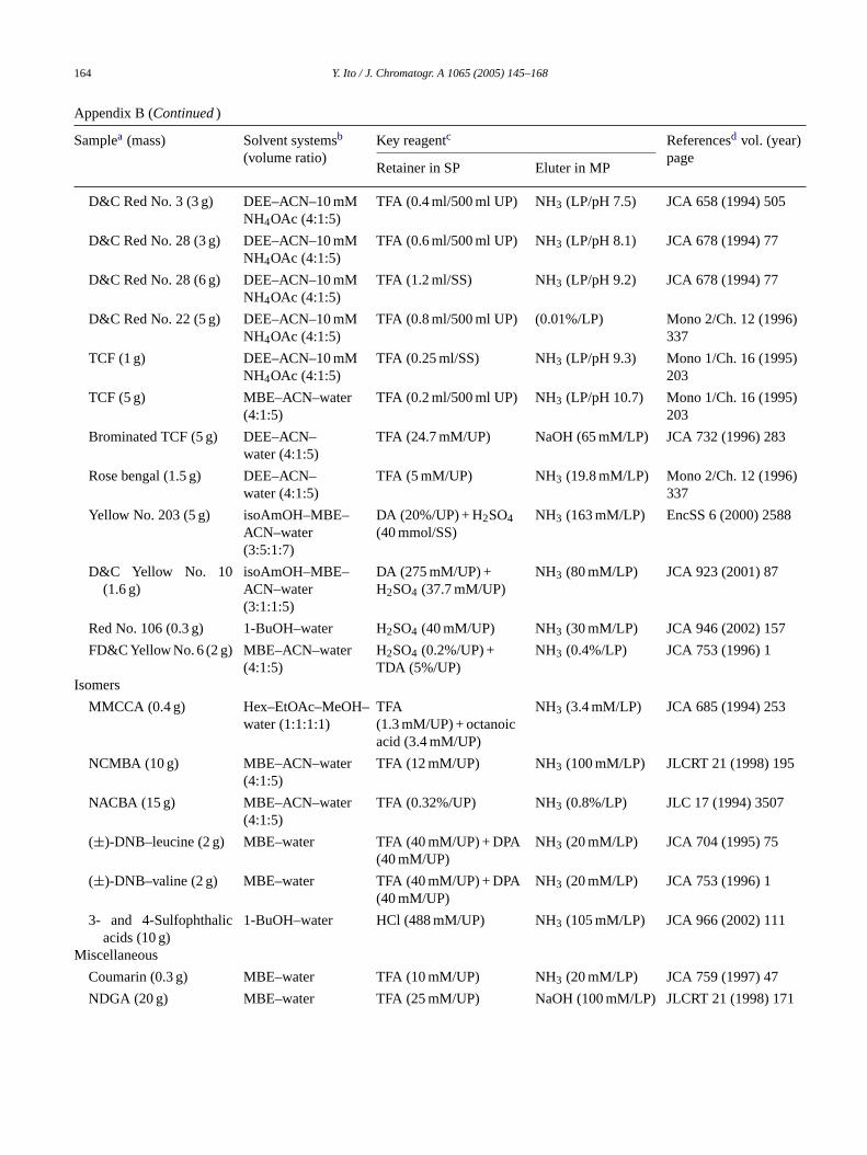
164 Y. Ito / J. Chromatogr. A 1065 (2005) 145–168
Appendix B (Continued)
Samplea (mass) Solvent systemsb
(volume ratio)Key reagentc Referencesd vol. (year)
pageRetainer in SP Eluter in MP
D&C Red No. 3 (3 g) DEE–ACN–10 mMNH4OAc (4:1:5)
TFA (0.4 ml/500 ml UP) NH3 (LP/pH 7.5) JCA 658 (1994) 505
D&C Red No. 28 (3 g) DEE–ACN–10 mMNH4OAc (4:1:5)
TFA (0.6 ml/500 ml UP) NH3 (LP/pH 8.1) JCA 678 (1994) 77
D&C Red No. 28 (6 g) DEE–ACN–10 mMNH4OAc (4:1:5)
TFA (1.2 ml/SS) NH3 (LP/pH 9.2) JCA 678 (1994) 77
D&C Red No. 22 (5 g) DEE–ACN–10 mMNH4OAc (4:1:5)
TFA (0.8 ml/500 ml UP) (0.01%/LP) Mono 2/Ch. 12 (1996)337
TCF (1 g) DEE–ACN–10 mMNH4OAc (4:1:5)
TFA (0.25 ml/SS) NH3 (LP/pH 9.3) Mono 1/Ch. 16 (1995)203
TCF (5 g) MBE–ACN–water(4:1:5)
TFA (0.2 ml/500 ml UP) NH3 (LP/pH 10.7) Mono 1/Ch. 16 (1995)203
Brominated TCF (5 g) DEE–ACN–water (4:1:5)
TFA (24.7 mM/UP) NaOH (65 mM/LP) JCA 732 (1996) 283
Rose bengal (1.5 g) DEE–ACN–water (4:1:5)
TFA (5 mM/UP) NH3 (19.8 mM/LP) Mono 2/Ch. 12 (1996)337
Yellow No. 203 (5 g) isoAmOH–MBE–ACN–water(3:5:1:7)
DA (20%/UP) + H2SO4(40 mmol/SS)
NH3 (163 mM/LP) EncSS 6 (2000) 2588
D&C Yellow No. 10(1.6 g)
isoAmOH–MBE–ACN–water(3:1:1:5)
DA (275 mM/UP) +H2SO4 (37.7 mM/UP)
NH3 (80 mM/LP) JCA 923 (2001) 87
Red No. 106 (0.3 g) 1-BuOH–water H2SO4 (40 mM/UP) NH3 (30 mM/LP) JCA 946 (2002) 157
FD&C Yellow No. 6 (2 g) MBE–ACN–water(4:1:5)
H2SO4 (0.2%/UP) +TDA (5%/UP)
NH3 (0.4%/LP) JCA 753 (1996) 1
Isomers
MMCCA (0.4 g) Hex–EtOAc–MeOH–water (1:1:1:1)
TFA(1.3 mM/UP) + octanoicacid (3.4 mM/UP)
NH3 (3.4 mM/LP) JCA 685 (1994) 253
NCMBA (10 g) MBE–ACN–water(4:1:5)
TFA (12 mM/UP) NH3 (100 mM/LP) JLCRT 21 (1998) 195
NACBA (15 g) MBE–ACN–water(4:1:5)
TFA (0.32%/UP) NH3 (0.8%/LP) JLC 17 (1994) 3507
(±)-DNB–leucine (2 g) MBE–water TFA (40 mM/UP) + DPA(40 mM/UP)
NH3 (20 mM/LP) JCA 704 (1995) 75
(±)-DNB–valine (2 g) MBE–water TFA (40 mM/UP) + DPA(40 mM/UP)
NH3 (20 mM/LP) JCA 753 (1996) 1
3- and 4-Sulfophthalicacids (10 g)
1-BuOH–water HCl (488 mM/UP) NH3 (105 mM/LP) JCA 966 (2002) 111
Miscellaneous
Coumarin (0.3 g) MBE–water TFA (10 mM/UP) NH3 (20 mM/LP) JCA 759 (1997) 47
NDGA (20 g) MBE–water TFA (25 mM/UP) NaOH (100 mM/LP) JLCRT 21 (1998) 171
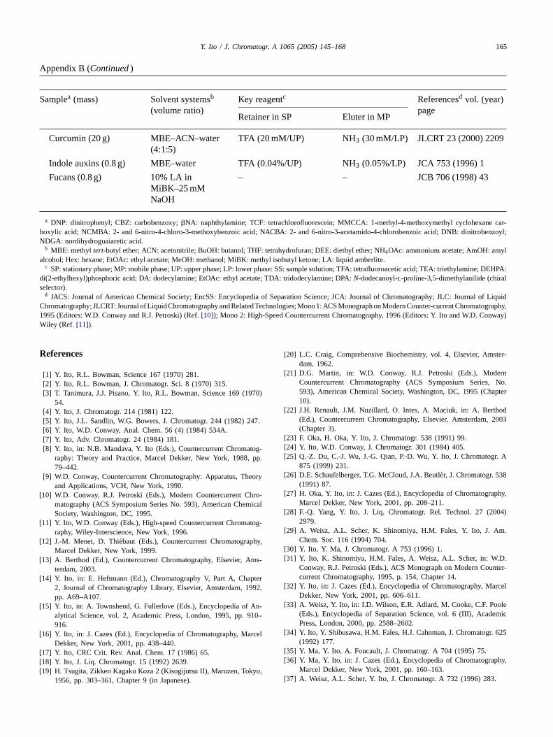
Y. Ito / J. Chromatogr. A 1065 (2005) 145–168 165
Appendix B (Continued)
Samplea (mass) Solvent systemsb
(volume ratio)Key reagentc Referencesd vol. (year)
pageRetainer in SP Eluter in MP
Curcumin (20 g) MBE–ACN–water(4:1:5)
TFA (20 mM/UP) NH3 (30 mM/LP) JLCRT 23 (2000) 2209
Indole auxins (0.8 g) MBE–water TFA (0.04%/UP) NH3 (0.05%/LP) JCA 753 (1996) 1
Fucans (0.8 g) 10% LA inMiBK–25 mMNaOH
– – JCB 706 (1998) 43
a DNP: dinitrophenyl; CBZ: carbobenzoxy;�NA: naphthylamine; TCF: tetrachlorofluorescein; MMCCA: 1-methyl-4-methoxymethyl cyclohexane car-boxylic acid; NCMBA: 2- and 6-nitro-4-chloro-3-methoxybenzoic acid; NACBA: 2- and 6-nitro-3-acetamido-4-chlorobenzoic acid; DNB: dinitrobenzoyl;NDGA: nordihydroguaiaretic acid.
b MBE: methyltert-butyl ether; ACN: acetonitrile; BuOH: butanol; THF: tetrahydrofuran; DEE: diethyl ether; NH4OAc: ammonium acetate; AmOH: amylalcohol; Hex: hexane; EtOAc: ethyl acetate; MeOH: methanol; MiBK: methyl isobutyl ketone; LA: liquid amberlite.
c SP: stationary phase; MP: mobile phase; UP: upper phase; LP: lower phase: SS: sample solution; TFA: tetrafluoroacetic acid; TEA: triethylamine; DEHPA:di(2-ethylhexyl)phosphoric acid; DA: dodecylamine; EtOAc: ethyl acetate; TDA: tridodecylamine; DPA:N-dodecanoyl-l-proline-3,5-dimethylanilide (chiralselector).
d JACS: Journal of American Chemical Society; EncSS: Encyclopedia of Separation Science; JCA: Journal of Chromatography; JLC: Journal of LiquidChromatography; JLCRT: Journal of Liquid Chromatography and Related Technologies; Mono 1: ACS Monograph on Modern Counter-current Chromatography,1995 (Editors: W.D. Conway and R.J. Petroski) (Ref.[10]); Mono 2: High-Speed Countercurrent Chromatography, 1996 (Editors: Y. Ito and W.D. Conway)Wiley (Ref. [11]).
References
[1] Y. Ito, R.L. Bowman, Science 167 (1970) 281.[2] Y. Ito, R.L. Bowman, J. Chromatogr. Sci. 8 (1970) 315.[3] T. Tanimura, J.J. Pisano, Y. Ito, R.L. Bowman, Science 169 (1970)
54.[4] Y. Ito, J. Chromatogr. 214 (1981) 122.[5] Y. Ito, J.L. Sandlin, W.G. Bowers, J. Chromatogr. 244 (1982) 247.[6] Y. Ito, W.D. Conway, Anal. Chem. 56 (4) (1984) 534A.[7] Y. Ito, Adv. Chromatogr. 24 (1984) 181.[8] Y. Ito, in: N.B. Mandava, Y. Ito (Eds.), Countercurrent Chromatog-
raphy: Theory and Practice, Marcel Dekker, New York, 1988, pp.79–442.
[9] W.D. Conway, Countercurrent Chromatography: Apparatus, Theoryand Applications, VCH, New York, 1990.
[10] W.D. Conway, R.J. Petroski (Eds.), Modern Countercurrent Chro-matography (ACS Symposium Series No. 593), American ChemicalSociety, Washington, DC, 1995.
[11] Y. Ito, W.D. Conway (Eds.), High-speed Countercurrent Chromatog-raphy, Wiley-Interscience, New York, 1996.
[12] J.-M. Menet, D. Thiebaut (Eds.), Countercurrent Chromatography,Marcel Dekker, New York, 1999.
[13] A. Berthod (Ed.), Countercurrent Chromatography, Elsevier, Ams-terdam, 2003.
[14] Y. Ito, in: E. Heftmann (Ed.), Chromatography V, Part A, Chapter2, Journal of Chromatography Library, Elsevier, Amsterdam, 1992,pp. A69–A107.
[15] Y. Ito, in: A. Townshend, G. Fullerlove (Eds.), Encyclopedia of An-alytical Science, vol. 2, Academic Press, London, 1995, pp. 910–916.
[ rcel
[[[ yo,
[20] L.C. Craig, Comprehensive Biochemistry, vol. 4, Elsevier, Amster-dam, 1962.
[21] D.G. Martin, in: W.D. Conway, R.J. Petroski (Eds.), ModernCountercurrent Chromatography (ACS Symposium Series, No.593), American Chemical Society, Washington, DC, 1995 (Chapter10).
[22] J.H. Renault, J.M. Nuzillard, O. Intes, A. Maciuk, in: A. Berthod(Ed.), Countercurrent Chromatography, Elsevier, Amsterdam, 2003(Chapter 3).
[23] F. Oka, H. Oka, Y. Ito, J. Chromatogr. 538 (1991) 99.[24] Y. Ito, W.D. Conway, J. Chromatogr. 301 (1984) 405.[25] Q.-Z. Du, C.-J. Wu, J.-G. Qian, P.-D. Wu, Y. Ito, J. Chromatogr. A
875 (1999) 231.[26] D.E. Schaufelberger, T.G. McCloud, J.A. Beutler, J. Chromatogr. 538
(1991) 87.[27] H. Oka, Y. Ito, in: J. Cazes (Ed.), Encyclopedia of Chromatography,
Marcel Dekker, New York, 2001, pp. 208–211.[28] F.-Q. Yang, Y. Ito, J. Liq. Chromatogr. Rel. Technol. 27 (2004)
2979.[29] A. Weisz, A.L. Scher, K. Shinomiya, H.M. Fales, Y. Ito, J. Am.
Chem. Soc. 116 (1994) 704.[30] Y. Ito, Y. Ma, J. Chromatogr. A 753 (1996) 1.[31] Y. Ito, K. Shinomiya, H.M. Fales, A. Weisz, A.L. Scher, in: W.D.
Conway, R.J. Petroski (Eds.), ACS Monograph on Modern Counter-current Chromatography, 1995, p. 154, Chapter 14.
[32] Y. Ito, in: J. Cazes (Ed.), Encyclopedia of Chromatography, MarcelDekker, New York, 2001, pp. 606–611.
[33] A. Weisz, Y. Ito, in: I.D. Wilson, E.R. Adlard, M. Cooke, C.F. Poole(Eds.), Encyclopedia of Separation Science, vol. 6 (III), AcademicPress, London, 2000, pp. 2588–2602.
. 625
phy,
16] Y. Ito, in: J. Cazes (Ed.), Encyclopedia of Chromatography, MaDekker, New York, 2001, pp. 438–440.
17] Y. Ito, CRC Crit. Rev. Anal. Chem. 17 (1986) 65.18] Y. Ito, J. Liq. Chromatogr. 15 (1992) 2639.19] H. Tsugita, Zikken Kagaku Koza 2 (Kisogijutsu II), Maruzen, Tok
1956, pp. 303–361, Chapter 9 (in Japanese).
[34] Y. Ito, Y. Shibusawa, H.M. Fales, H.J. Cahnman, J. Chromatogr(1992) 177.
[35] Y. Ma, Y. Ito, A. Foucault, J. Chromatogr. A 704 (1995) 75.[36] Y. Ma, Y. Ito, in: J. Cazes (Ed.), Encyclopedia of Chromatogra
Marcel Dekker, New York, 2001, pp. 160–163.[37] A. Weisz, A.L. Scher, Y. Ito, J. Chromatogr. A 732 (1996) 283.
166 Y. Ito / J. Chromatogr. A 1065 (2005) 145–168
Glossary
Archimedean screw effect (head and tail):when the coiled column filledwith two solvent phases is subjected to a planetary motion (rotat-ing centrifugal force field), both phases tend to advance toward oneend (head) of an open coil determined by the Archimedean screw.However, in a closed coil type-J synchronous planetary motion givesan advantage for the lighter phase to occupy the head end while theheavier phase is pushed back toward the other end called the tail.This phenomenon is efficiently used for retaining the stationary phaseby either introducing the heavier phase from the head or the lighterphase from the tail into the rotating coiled column filled with theother phase as the stationary phase.
Carryover of the stationary phase:when the mobile phase is elutedthrough the column previously filled with the stationary phase, itgradually displaces the stationary phase until it elutes out from thecolumn (solvent front) and the hydrodynamic equilibrium is estab-lished through the column. If the stationary phase keeps flowing outfrom the column after the emergence of the solvent front, it is calledcarryover of the stationary phase or stripping. Usually this tapers offshortly after the solvent front. Continued carryover of the stationaryphase not only significantly reduces the resolution, but also disturbsthe tracing of the elution curves. This complication may be causedby various reasons including a high flow rate of the mobile phase;long settling timeof the solvent system (over 20 s) especially whenthe upper phase is eluted from the tail toward the head; emulsificationof the sample compartment when the sample contains detergent-likecompounds such as saponin; precipitate formation in the column dur-ing pH-zone-refining CCC, etc.
Chiral CCC: enantiomers can be resolved if a suitable chiral selectoris dissolved in the stationary phase. For example,N-dodecanoyl-
C n a0 ml
C i-rietye tontinu-uentribed
C natherThecom-
ocessupperase.
D ra-forceop inusesn at-the
lumn.shak-d then the
d elu-umn),ectingice.f the
E
Elution mode: this term indicates how to introduce the mobile phase(upper or lower) into the rotating coil (from the head or the tail). Offour combinations, only two elution modes should be used in HSCCC,i.e., either the lower phase from the head toward the tail or the upperphase from the tail toward the head.
Head and tail of the rotating coil:see Archimedean screw effect.High-speed CCC (HSCCC) (type-J):the most advanced form of the CCC
system using a multilayer coil separation column, which undergoes atype-J synchronous planetary motion (see Fig. 1). The method coversanalytical (microgram) to preparative (10 g) scale separations usuallyin a few hours at a high partition efficiency up to a few thousandtheoretical plates.
Hydrodynamic equilibrium:when the column filled with the stationaryphase is eluted with the mobile phase, the planetary motion producesan Archimedean screw effect, which moves the upper phase towardthe head of the coil. If the mobile phase is the lower phase eluted fromthe head toward the tail, the movement of the stationary upper phasetoward the head is offset by the flow of the mobile lower phase towardthe tail, resulting in a steady hydrodynamic balance between the twophases where a given amount of the stationary phase is permanentlyretained in the coil. In this case, a pressure gradient is formed fromthe head toward the tail (outlet) where the pressure drops down to nearthe atmospheric level. This hydrodynamic state is quite stable as far asthe flow rate of the mobile phase is within a reasonable range. On theother hand, if the upper phase is pumped into the tail of the coil filledwith the lower phase, both the Archimedean Screw effect and the flowof the mobile phase pushes two phases toward the outlet (the upperphase moves faster than the lower phase through the coil) producinga decreasing pressure gradient from the head (outlet) toward the tail(inlet). This hydrodynamic condition often creates a negative pressure
f thef theativein theever,ubingto arof the
is as theust
nhase
lumntioned
l sol-ga-gher
M hich
M aredoax-iled
i.d.for
aseste of
N lot-in therying
s usu-igh
,
l-proline-3,5-dimethylanilide is effectively used for resolving (±)-dinitrobenzoyl-amino acids.
olumn capacity (VC): the total volume of the separation column. Itypical commercial HSCCC, the column capacity ranges from 10(analytical) to 1 l (preparative).
ounter-current chromatography (CCC):continuous liquid–liquid parttion technique without a solid support. The method employs vaof partition systems using either gravitational or centrifugal forcretain the stationary phase in the column. The method allows coous elution of the mobile phase and on-line monitoring of the efflas in liquid chromatography. High-speed CCC (HSCCC) is descbelow.
ounter-current distribution (CCD) method:a discontinuous extractiomethod using a set of multiple partition units. The method was rwidely used for purification of natural products during the 1950s.Craig apparatus is the most advanced form using hundreds ofplex glass partition units connected in series. Each partition prconsists of three steps, i.e., mixing, settling and transfer of themobile phase to the next unit containing the lower stationary ph
egassing of two-phase solvent system:HSCCC produces a pressure gdient from the head toward the tail by an Archimedean screwand a drag of the mobile phase flow. Although the pressure drHSCCC is usually no more than a few hundred p.s.i., it often cabubble formation in the outlet where the pressure drops to amospheric level. Therefore, it is desirable to eliminate air fromtwo-phase solvent system before application to the separation coThis can be done in a separatory funnel as follows: after eaching the contents, invert the funnel and open the stopcock to voiair. This procedure should be repeated at least five times. Whelighter upper phase is used as the mobile phase (tail to heation mode which tends to produce negative pressure in the colthe degassing should be more completely performed by connthe outlet of the inverted funnel to a vacuum line once or twThe cock should be opened only momentarily to avoid a loss oorganic solvent.
luter: see retainer and eluter.
at the inlet of the column which tends to suck an extra amount omobile phase from the reservoir through a pair of check values ometering pump, increasing the flow rate of the mobile phase. Negcolumn pressure also tends to cause a formation of air bubblescolumn causing the problem in recording the elution curve. Howthese problems can be eliminated by applying a piece of narrow tat the outlet of the monitor to raise the inlet column pressurepositive range. Also, when thesettling timeof the solvent is ove20 s, this hydrodynamic condition tends to cause a gradual lossstationary phase from the column (carryover). Therefore, if therechoice of the mobile phase, it is safer to use the lower phase amobile phase pumping it from the head of the coiled column. It mbe mentioned, however, that if thesettling time is short (less tha10 s) and the partition coefficient is suitable, the upper mobile pwill produce an excellent separation, provided that the inlet copressure is always kept above the atmospheric level as menearlier.
ogP: partition coefficient of drugs measured by a binary two-phasevent system composed ofn-octanol–water and expressed in a lorithmic scale. It indicates hydrophobicity of the drug where a hilogP value is considered to be more effective.obile phase:one of the two solvent phases, either upper or lower, w
elutes through the column.ultilayer coil: a separation column used for HSCCC. It is prep
from a long piece of polytetrafluoroethylene (PTFE) tubing by cially winding it around a spool-shaped holder making multiple colayers. Usually three different sizes of tubing are used: ca. 1 mmfor analytical, 1.6 mm i.d. for semipreparative, and 2.6 mm i.d.preparative separations. It provides efficient mixing of the two phand a high retention of the stationary phase under a high flow rathe mobile phase.
on-linear isotherm:isotherm is a line drawn on a graph paper by pting the solute concentration in the upper phase against thatlower phase in an equilibrated two-phase solvent system by vathe solute concentration at a given temperature. Neutral soluteally form a straight line (linear isotherm) except for extremely hconcentration, indicating the stable partition coefficient (K). However
Y. Ito / J. Chromatogr. A 1065 (2005) 145–168 167
when charged analytes are partitioned in a neutral two-phase solventsystem, the isotherm tends to form a curved line (non-linear isotherm)due to self-protonation or deprotonation, which alters theirK values.If this occurs within a chromatographic column, the solute forms askewed peak characterized by its prolonged front and steep trailingborder.
Partition coefficient (K):the partition coefficient is a ratio of the soluteconcentration between equilibrated two immiscible solvent phases ata given temperature (usually at around 20◦C). ConventionallyK isexpressed as the solute concentration in the stationary phase dividedby that in the mobile phase as in liquid chromatography. The mostsuitableK values for HSCCC is 0.5≤K≤ 1, while the bestK valuefor other CCC systems and CCD is around 1. The difference in thesuitableK range between HSCCC and other CCC systems derivesfrom an efficient mixing of the two phases in the HSCCC column,which tends to produce longitudinal spreading of the solute bandfor the sample with largeK values. Since one can use either upperor lower phase as the stationary phase in CCC, it is convenient toexpress the ratio temporarily as solute concentration in the upperphase divided by that in the lower phase, and to avoid a confusion itshould be specified asKU/L . Thus, if KU/L is 2, one should use thelower phase as the stationary phase to makeK= 0.5. If KU/L = 1, eitherphase can be the stationary phase to getK= 1. As explained above (inhydrodynamic equilibrium), if one has a choice, the upper phase ismore suitable to be used as the stationary phase for various reasons,and therefore it is recommended to bring 0.5≤KU/L ≤ 1 and use theupper phase as the stationary phase. (Recently, IUPAC recommendedthat distribution ratio,D, should be used for non-equilibrium situationsin HSCCC.)
Partition efficiency:the efficiency of separation in HSCCC may be ex-peakffi-
ng its
P ured
eaks,
ion).p sed
ecificr sat-y aof
R one-se tophase
s forre theminesl
andueousn alsoormalter toin the
Rn. Itution.pacitywith0%bile
Separation factor:the ratio of partition coefficients between two solutes iscalled separation factor (α) (in some casesβ) (K1/K2, K1 ≥K2). It isan important parameter, which indicates the peak resolution betweenthe two components. According to our experience, in the commer-cial HSCCC centrifuge (semipreparative column, 1.6 mm i.d. and ca.300 ml capacity),α > 1.5 is needed to resolve two peaks at the suitableK values and over 50% retention of the stationary phase. For a givenpair of two solutes,α varies with the hydrophobicity of the solventsystem as well as its composition.
Settling time: this is a time required for the two phases (2 ml each)to settle into two clear layers after gently mixed in a test tube(13 mm× 100 mm) or graduated cylinder (5 ml capacity). The test maybe performed by capping the container, which is gently inverted forfive times to thoroughly mix the contents. However, vigorous shakingof the contents for five times showed only a slight difference of thesettling time. It has been shown that the settling time well correlateswith the retention of the stationary phase in the coiled column inHSCCC. The shorter the settling time, the higher is the retention ofthe stationary phase. If it is shorter than 10 s, one can expect over70% retention of the stationary phase. It is desirable that the settlingtime is less than 20 s, which usually gives over 50% retention undera proper flow rate of the mobile phase.
Stationary phase:conventional liquid chromatography uses a solid sup-port in the column which is called stationary phase. CCC uses nosolid support and instead retains one liquid phase of the equilibratedtwo-phase solvent system in the column as the stationary phase. InHSCCC, the stationary phase is retained in the column utilizing thecombined effect of a multilayer coil configuration and a special typeof synchronous planetary motion (type-J shown in Fig. 1). For goodresults the amount of the stationary phase retained in the column
T ac-
lumehasese re-ently,
of the.
T tu-qui-es,mong
ic sol-pro-
en-uc-stems,po-
onitriler com-suchsuch–ethylusefulsol-
have andentventepar-
statelmost
T n-ch is
pressed by two terms, i.e., theoretical plate number (TP) andresolution (Rs), each of which is described below. The partition eciency increases with an increasing the tube length and reducii.d.
eak resolution (Rs): the resolution between two solute peaks is measusing the following equation:Rs = 2(R2 −R1)/(W2 +W1), where R1
andR2 are the retention volumes of the first and the second pandW1 andW2, their peak widths. The separation ofRs = 1 gives 95%pure material andRs = 1.5, 99.7% pure material (baseline separat
H-zone-refining CCC:pH-zone-refining CCC produces a train of furectangular solute peaks called pH-zones, each with its sppH. Each zone contains highly concentrated solute often neauration level. It is separated from the neighboring zone bnarrow strip called mixing zone, which contains a mixtureimpurities.
etainer and eluter:these are the most important reagents in pH-zrefining CCC. The retainer is added to the stationary organic pharetain the analytes, and the eluter added to the mobile aqueousto elute the analytes. TFA and triethylamine are typical retainerthe separation of acidic and basic compounds, respectively, whestationary phase typically is the organic phase. The retainer deterthe analyte concentration in the stationary phase. NH4OH and HCare commonly used as the eluter for the separation of acidicbasic compounds, respectively. The eluter always stays in the aqmobile phase to serve as a counterion. pH-zone-refining CCC cabe performed using the organic phase as the mobile phase (ndisplacement mode). In this case the retainer becomes the eluelute the analytes, and the eluter becomes the retainer to retaanalytes in the aqueous stationary phase.
etention of the stationary phase:a volume of the stationary phase (VS),which stays permanently within the column during the separatiois one of the most important parameters to determine the resolIt is expressed as a percentage relative to the total column ca(VC). High retention of 70% is expected from a solvent systema shortsettling timeof less than 10 s, while the retention of over 5is satisfactory. It is improved by reducing the flow rate of the mophase.
should be over 50% of the total column capacity.heoretical plate (TP):the TP is computed from the chromatogram
cording to the conventional formula, i.e., TP = (4R/W)2, whereR isthe retention volume (or time) of the peak maximum andW the peakwidth (the base of the triangle fitted to the peak) measured in vo(or time). In CCC, TP changes with the amount of stationary pretained in the column, e.g., TP increases as the stationary phatention deceases approaching infinity at 0% retention. ConsequTP can be used as a valid parameter only when the retentionstationary phase is within a reasonable range such as over 50%
wo-phase solvent system:each system consists of a pair of mually immiscible solvents, upper and lower phases, usually elibrated in a separatory funnel. It is divided into three typorganic–organic, organic–aqueous and aqueous–aqueous. Athose the aqueous–aqueous solvent system is free of organvent and mainly used for separation of biopolymers such asteins, but it is not efficiently applied for HSCCC due to extsive emulsification by vigorous mixing in the column. HSCCC scessfully uses organic–organic and organic–aqueous solvent sywhich are classified according to the hydrophobicity of the lesslar phase. Hydrophobic solvent systems such as hexane–acetand hexane–ethanol–water are used for separation of non-polapounds such as fatty acids while hydrophilic solvent systemas butanol–water is used for separation of polar compoundsas peptides. Intermediate solvent systems such as hexaneacetate–methanol–water and chloroform–methanol–water arefor separation of moderately hydrophobic compounds. Binaryvent systems such as ethyl acetate–water and butanol–waterparticular feature that the composition of each phase is indepeof a volume ratio of the two solvents. The amount of the solsystem required for HSCCC is considerably less than that for prative HPLC since the analytes are eluted in a more concentratedespecially in pH-zone-refining CCC where the analytes are asaturated in the mobile phase.
ype-J coil planet centrifuge:a centrifuge, which provides type-J sychronous planetary motion to the column holder the axis of whiparallel to the centrifuge axis (see Fig. 1).

168 Y. Ito / J. Chromatogr. A 1065 (2005) 145–168
Type-J Synchronous planetary motion:a unique type of planetary motion(so called because the flow tubes form a letter J figure as shown in Fig.1) of the column holder, which rotates around its own axis once duringone revolution around the central axis of the centrifuge in the samedirection. The system prevents the flow tubes from twisting duringcolumn rotation, and produces an excellent mixing and high retentionof the stationary phase in a multilayer coil separation column.
Zone pH (pHzone): it indicates pH of the solute zone in pH-zone-refiningCCC which is expressed by pHzone= pKa + log[(KDS/KS) − 1], whereKDS is the partition ratio of solute S (an indicator for solute hy-drophobicity) andKS, the dissociation constant of the solute. Accord-ing to the theoretical analysis two solutes, which differ their zonepH values by 0.2 or greater can be resolved in pH-zone-refiningCCC.