Embed Size (px)
Citation preview
7
Reverse Regeneration Technique of BLDC Motor for Capacitor Charging
Bikram Das, Suvamit Chakraborty, Prabir Ranjan Kasari & Abanishwar Chakrabarti
Abstract— This paper illustrates the working of a BLDC motor in the forward motoring and reverse regeneration mode. It proposes a simple method of braking with energy regeneration for a brushless dc motor. This action is accomplished through the inversion of the signals given by the position sensor. When the brake signal is applied, the stator field is reversed 180 electric degrees compared with the presented method. The proposed solution simultaneously achieves dual goals - electric brake and the energy regeneration without using additional converter, ultra-capacitor, or complex winding-changeover technique. Charging of the battery has been understood by looking into the charging current and voltage waveform of the capacitor connected in parallel to the source. The speed control model of the BLDC motor is built and simulated in this paper and different parameters like speed, torque, phase currents, hall sensors output etc has been analyzed. The motor model built in PSIM systems is then tied into the MATLAB model with the help of a SIMCOUPLER tool.
Keywords— BLDC, motoring, reverse regeneration, capacitor charging, PSIM, MATLAB.
I. Introduction Permanent magnet brushless DC motors (PMBLDC) find wide applications in industries due to their high power density and ease of control. These motors are generally controlled using a 3 phase power semiconductor bridge. For starting and providing proper commutation sequence to turn on the power devices in the inverter bridge the rotor position sensors are required. Based on the rotor position, the power devices are commutated sequentially every 60 degrees. To achieve desired level of performance the motor requires suitable speed controllers. Considering the ready availability of electricity and the myriad uses for mechanical energy, it's no surprise that electric motors are widely used. According to the U.S Department of Energy fact sheet (DOE/GO-10096-314), electric motors are responsible for consuming more than half of all the electrical energy used in the World [1]. PMBL motors can be considered a kind of 3 phase synchronous motor, having permanent magnets on the rotor, replacing the mechanical commutator and brush gear. Commutation is accomplished by electronic switches, which supply current to the motor windings in synchronization with the rotor position. Brushless dc (BLDC) motor drives are becoming widely used in various consumer and industrial systems, such a servo motor drives, home appliances, computer peripherals, and automotive applications. In general, the overall system consists of three parts: (i) power conversion PWM inverters B. Das, Electrical Engineering Department. NIT, Agartala, Tripur, India. S. Chakraborty, Electrical Engg. Deptt, NIT, Agartala, Tripura, India. P. Rn. Kasari, Electrical Engg. Deptt., NIT, Agartala, Tripura, India. A.Chakrabarti, Electrical Engg. Deptt., NIT Agartala,Tripura,India.
(ii) BLDC motor and load and (iii) speed, torque, and current controller. Therefore, exact understanding of each part is a prerequisite for analysis and prediction of the overall system operation. Before now, several simulation models have been proposed for the analysis of BLDC motor drives. These models are based on state-space equations, Fourier series, and the d-q axis model [2]. In this paper we propose a simulation model for an entire BLDC motor drive to obtain controlled speed and also to analyze the complete system along with the forward motoring and reverse regeneration technique.
II. Principle and Construction BLDC motors are a type of synchronous motor. This means the magnetic field generated by the stator and the magnetic field generated by the rotor rotates at the same frequency. BLDC motors do not experience the ―slip‖ that is normally seen in induction motors. The 3-phase motors are the most popular and widely used [3]. The analysis is based on the following assumptions for simplification (i)The motor is not saturated (ii) Stator resistances of all the windings are equal and self & mutual inductances are constant (iii) Power semiconductor devices in the inverter are ideal (iv) Iron losses are negligible. Most of the BLDC motors have three stator windings connected in star fashion. Each of these windings is constructed with numerous coils interconnected to form a winding. One or more coils are placed in the slots and they are interconnected to make a winding. Each of these windings is distributed over the stator periphery to form an even numbers of poles [4]. There are two types of stator windings variant trapezoidal and sinusoidal motors. This differentiation is made on the basis of the interconnection of the coils in the stator windings to give the different types of back emf. The rotor is made of permanent magnet and can vary from two to eight pairs with alternate North (N) and South(S) poles. Based on the required magnetic field density in the rotor, the proper magnetic materials are chosen to make the rotor. The fig. 1 below shows the complete arrangement of the BLDC motor drive system.
Figure 1 Complete arrangement of the BLDC motor drive system.
Proc. of the Intl. Conf. on Advances in Computing, Electronics and Communication-- ACEC 2013 Copyright © Institute of Research Engineers and Doctors. All rights reserved.
ISBN: 978-981-07-7965-8 doi:10.3850/ 978-981-07-7965-8_02
8
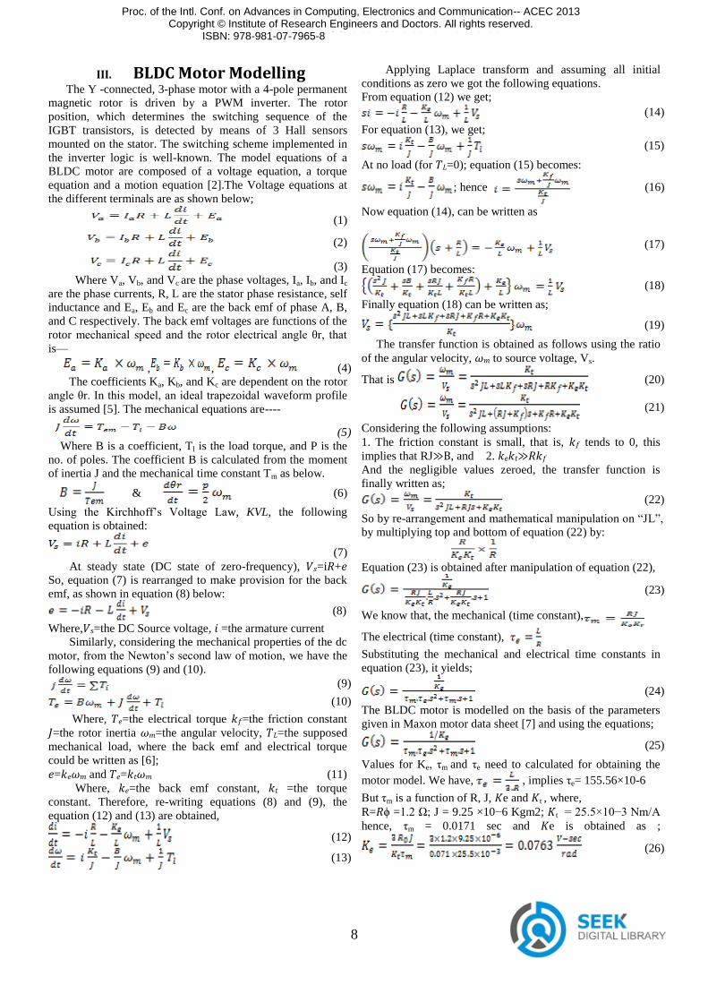
III. BLDC Motor Modelling The Y -connected, 3-phase motor with a 4-pole permanent magnetic rotor is driven by a PWM inverter. The rotor position, which determines the switching sequence of the IGBT transistors, is detected by means of 3 Hall sensors mounted on the stator. The switching scheme implemented in the inverter logic is well-known. The model equations of a BLDC motor are composed of a voltage equation, a torque equation and a motion equation [2].The Voltage equations at the different terminals are as shown below;
(1)
(2)
(3) Where Va, Vb, and Vc are the phase voltages, Ia, Ib, and Ic are the phase currents, R, L are the stator phase resistance, self inductance and Ea, Eb and Ec are the back emf of phase A, B, and C respectively. The back emf voltages are functions of the rotor mechanical speed and the rotor electrical angle θr, that
is—
, , (4) The coefficients Ka, Kb, and Kc are dependent on the rotor angle θr. In this model, an ideal trapezoidal waveform profile is assumed [5]. The mechanical equations are----
(5) Where B is a coefficient, Tl is the load torque, and P is the no. of poles. The coefficient B is calculated from the moment of inertia J and the mechanical time constant Tm as below.
& (6)
Using the Kirchhoff’s Voltage Law, KVL, the following equation is obtained:
(7) At steady state (DC state of zero-frequency), 𝑉𝑠=i𝑅+𝑒 So, equation (7) is rearranged to make provision for the back emf, as shown in equation (8) below:
(8)
Where,𝑉s=the DC Source voltage, 𝑖 =the armature current Similarly, considering the mechanical properties of the dc motor, from the Newton’s second law of motion, we have the following equations (9) and (10). (9)
(10)
Where, 𝑇𝑒=the electrical torque 𝑘𝑓=the friction constant 𝐽=the rotor inertia 𝜔𝑚=the angular velocity, 𝑇𝐿=the supposed mechanical load, where the back emf and electrical torque could be written as [6]; 𝑒=𝑘𝑒𝜔𝑚 and 𝑇𝑒=𝑘𝑡𝜔𝑚 (11) Where, 𝑘𝑒=the back emf constant, 𝑘𝑡 =the torque constant. Therefore, re-writing equations (8) and (9), the equation (12) and (13) are obtained,
(12)
(13)
Applying Laplace transform and assuming all initial conditions as zero we got the following equations. From equation (12) we get;
(14)
For equation (13), we get; (15)
At no load (for 𝑇𝐿=0); equation (15) becomes:
; hence (16)
Now equation (14), can be written as
(17)
Equation (17) becomes: (18)
Finally equation (18) can be written as;
(19)
The transfer function is obtained as follows using the ratio of the angular velocity, 𝜔𝑚 to source voltage, Vs.
That is (20)
(21)
Considering the following assumptions: 1. The friction constant is small, that is, 𝑘𝑓 tends to 0, this implies that RJ≫B, and 2. 𝑘𝑒𝑘𝑡≫𝑅𝑘𝑓 And the negligible values zeroed, the transfer function is finally written as;
(22)
So by re-arrangement and mathematical manipulation on ―JL‖,
by multiplying top and bottom of equation (22) by:
Equation (23) is obtained after manipulation of equation (22),
(23)
We know that, the mechanical (time constant),
The electrical (time constant),
Substituting the mechanical and electrical time constants in equation (23), it yields;
(24)
The BLDC motor is modelled on the basis of the parameters given in Maxon motor data sheet [7] and using the equations;
(25)
Values for Ke, τm and τe need to calculated for obtaining the motor model. We have, , implies τe= 155.56×10⁻⁶
But τm is a function of R, J, 𝐾e and 𝐾t , where, R=𝑅ϕ =1.2 Ω; J = 9.25 ×10⁻⁶ Kgm2; 𝐾t = 25.5×10⁻³ Nm/A hence, τm = 0.0171 sec and 𝐾e is obtained as ;
(26)
Proc. of the Intl. Conf. on Advances in Computing, Electronics and Communication-- ACEC 2013 Copyright © Institute of Research Engineers and Doctors. All rights reserved.
ISBN: 978-981-07-7965-8 doi:10.3850/ 978-981-07-7965-8_02
9
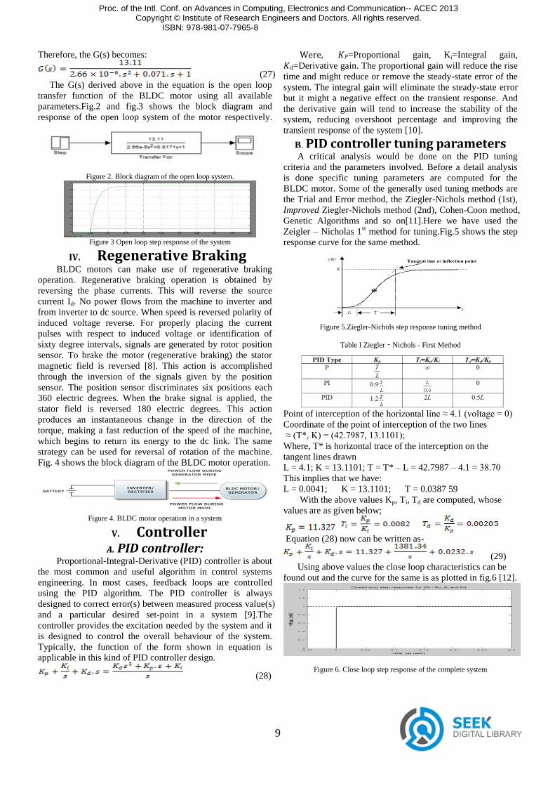
Therefore, the G(s) becomes:
(27) The G(s) derived above in the equation is the open loop transfer function of the BLDC motor using all available parameters.Fig.2 and fig.3 shows the block diagram and response of the open loop system of the motor respectively.
Figure 2. Block diagram of the open loop system.
Figure 3 Open loop step response of the system
IV. Regenerative Braking BLDC motors can make use of regenerative braking operation. Regenerative braking operation is obtained by reversing the phase currents. This will reverse the source current Id. No power flows from the machine to inverter and from inverter to dc source. When speed is reversed polarity of induced voltage reverse. For properly placing the current pulses with respect to induced voltage or identification of sixty degree intervals, signals are generated by rotor position sensor. To brake the motor (regenerative braking) the stator magnetic field is reversed [8]. This action is accomplished through the inversion of the signals given by the position sensor. The position sensor discriminates six positions each 360 electric degrees. When the brake signal is applied, the stator field is reversed 180 electric degrees. This action produces an instantaneous change in the direction of the torque, making a fast reduction of the speed of the machine, which begins to return its energy to the dc link. The same strategy can be used for reversal of rotation of the machine. Fig. 4 shows the block diagram of the BLDC motor operation.
Figure 4. BLDC motor operation in a system
V. Controller A. PID controller:
Proportional-Integral-Derivative (PID) controller is about the most common and useful algorithm in control systems engineering. In most cases, feedback loops are controlled using the PID algorithm. The PID controller is always designed to correct error(s) between measured process value(s) and a particular desired set-point in a system [9].The controller provides the excitation needed by the system and it is designed to control the overall behaviour of the system. Typically, the function of the form shown in equation is applicable in this kind of PID controller design.
(28)
Were, 𝐾𝑃=Proportional gain, Ki=Integral gain, 𝐾d=Derivative gain. The proportional gain will reduce the rise time and might reduce or remove the steady-state error of the system. The integral gain will eliminate the steady-state error but it might a negative effect on the transient response. And the derivative gain will tend to increase the stability of the system, reducing overshoot percentage and improving the transient response of the system [10].
B. PID controller tuning parameters A critical analysis would be done on the PID tuning criteria and the parameters involved. Before a detail analysis is done specific tuning parameters are computed for the BLDC motor. Some of the generally used tuning methods are the Trial and Error method, the Ziegler-Nichols method (1st), Improved Ziegler-Nichols method (2nd), Cohen-Coon method, Genetic Algorithms and so on[11].Here we have used the Zeigler – Nicholas 1st method for tuning.Fig.5 shows the step response curve for the same method.
Figure 5.Ziegler-Nichols step response tuning method
Table I Ziegler‐Nichols - First Method
Point of interception of the horizontal line ≈ 4.1 (voltage = 0) Coordinate of the point of interception of the two lines ≈ (T*, K) = (42.7987, 13.1101); Where, T* is horizontal trace of the interception on the tangent lines drawn L = 4.1; K = 13.1101; T = T* – L = 42.7987 – 4.1 ≈ 38.70 This implies that we have: L = 0.0041; K = 13.1101; T = 0.0387 59 With the above values Kp, Ti, Td are computed, whose values are as given below;
Equation (28) now can be written as-
(29) Using above values the close loop characteristics can be found out and the curve for the same is as plotted in fig.6 [12].
Figure 6. Close loop step response of the complete system
Proc. of the Intl. Conf. on Advances in Computing, Electronics and Communication-- ACEC 2013 Copyright © Institute of Research Engineers and Doctors. All rights reserved.
ISBN: 978-981-07-7965-8 doi:10.3850/ 978-981-07-7965-8_02
10
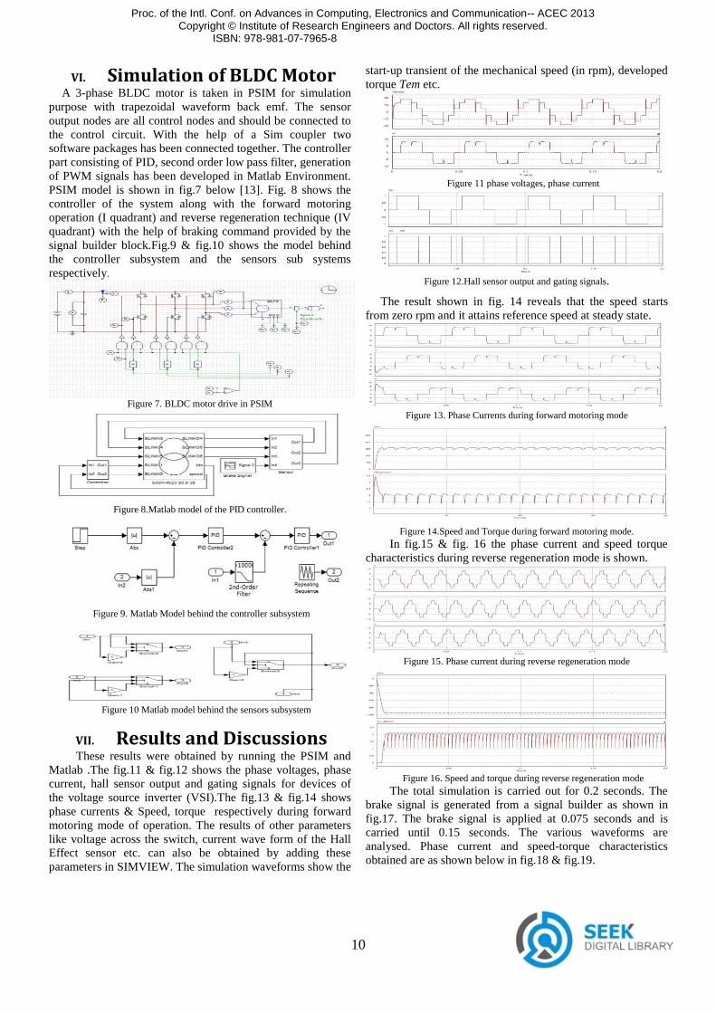
VI. Simulation of BLDC Motor A 3-phase BLDC motor is taken in PSIM for simulation
purpose with trapezoidal waveform back emf. The sensor output nodes are all control nodes and should be connected to the control circuit. With the help of a Sim coupler two software packages has been connected together. The controller part consisting of PID, second order low pass filter, generation of PWM signals has been developed in Matlab Environment. PSIM model is shown in fig.7 below [13]. Fig. 8 shows the controller of the system along with the forward motoring operation (I quadrant) and reverse regeneration technique (IV quadrant) with the help of braking command provided by the signal builder block.Fig.9 & fig.10 shows the model behind the controller subsystem and the sensors sub systems respectively.
Figure 7. BLDC motor drive in PSIM
Figure 8.Matlab model of the PID controller.
Figure 9. Matlab Model behind the controller subsystem
Figure 10 Matlab model behind the sensors subsystem
VII. Results and Discussions These results were obtained by running the PSIM and Matlab .The fig.11 & fig.12 shows the phase voltages, phase current, hall sensor output and gating signals for devices of the voltage source inverter (VSI).The fig.13 & fig.14 shows phase currents & Speed, torque respectively during forward motoring mode of operation. The results of other parameters like voltage across the switch, current wave form of the Hall Effect sensor etc. can also be obtained by adding these parameters in SIMVIEW. The simulation waveforms show the
start-up transient of the mechanical speed (in rpm), developed torque Tem etc.
Figure 11 phase voltages, phase current
Figure 12.Hall sensor output and gating signals.
The result shown in fig. 14 reveals that the speed starts from zero rpm and it attains reference speed at steady state.
Figure 13. Phase Currents during forward motoring mode
Figure 14.Speed and Torque during forward motoring mode. In fig.15 & fig. 16 the phase current and speed torque characteristics during reverse regeneration mode is shown.
Figure 15. Phase current during reverse regeneration mode
Figure 16. Speed and torque during reverse regeneration mode
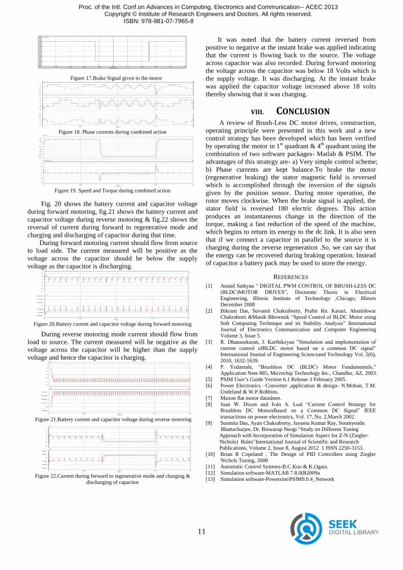
The total simulation is carried out for 0.2 seconds. The brake signal is generated from a signal builder as shown in fig.17. The brake signal is applied at 0.075 seconds and is carried until 0.15 seconds. The various waveforms are analysed. Phase current and speed-torque characteristics obtained are as shown below in fig.18 & fig.19.
Proc. of the Intl. Conf. on Advances in Computing, Electronics and Communication-- ACEC 2013 Copyright © Institute of Research Engineers and Doctors. All rights reserved.
ISBN: 978-981-07-7965-8 doi:10.3850/ 978-981-07-7965-8_02
11
Figure 17.Brake Signal given to the motor
Figure 18. Phase currents during combined action
Figure 19. Speed and Torque during combined action
Fig. 20 shows the battery current and capacitor voltage during forward motoring, fig.21 shows the battery current and capacitor voltage during reverse motoring & fig.22 shows the reversal of current during forward to regenerative mode and charging and discharging of capacitor during that time. During forward motoring current should flow from source to load side. The current measured will be positive as the voltage across the capacitor should be below the supply voltage as the capacitor is discharging.
Figure 20.Battery current and capacitor voltage during forward motoring
During reverse motoring mode current should flow from load to source. The current measured will be negative as the voltage across the capacitor will be higher than the supply voltage and hence the capacitor is charging.
Figure 21.Battery current and capacitor voltage during reverse motoring
Figure 22.Current during forward to regenerative mode and charging &
discharging of capacitor
It was noted that the battery current reversed from positive to negative at the instant brake was applied indicating that the current is flowing back to the source. The voltage across capacitor was also recorded. During forward motoring the voltage across the capacitor was below 18 Volts which is the supply voltage. It was discharging. At the instant brake was applied the capacitor voltage increased above 18 volts thereby showing that it was charging.
VIII. CONCLUSION A review of Brush-Less DC motor drives, construction, operating principle were presented in this work and a new control strategy has been developed which has been verified by operating the motor in 1st quadrant & 4th quadrant using the combination of two software packages- Matlab & PSIM. The advantages of this strategy are- a) Very simple control scheme; b) Phase currents are kept balance.To brake the motor (regenerative braking) the stator magnetic field is reversed which is accomplished through the inversion of the signals given by the position sensor. During motor operation, the rotor moves clockwise. When the brake signal is applied, the stator field is reversed 180 electric degrees. This action produces an instantaneous change in the direction of the torque, making a fast reduction of the speed of the machine, which begins to return its energy to the dc link. It is also seen that if we connect a capacitor in parallel to the source it is charging during the reverse regeneration .So, we can say that the energy can be recovered during braking operation. Instead of capacitor a battery pack may be used to store the energy.
REFERENCES [1] Anand Sathyan ― DIGITAL PWM CONTROL OF BRUSH-LESS DC
(BLDC)MOTOR DRIVES‖, Doctorate Thesis in Electrical Engineering, Illinois Institute of Technology ,Chicago, Illinois December 2008
[2] Bikram Das, Suvamit Chakraborty, Prabir Rn. Kasari, Abanishwar Chakraborti &Manik Bhowmik ―Speed Control of BLDC Motor using Soft Computing Technique and its Stability Analysis‖ International
Journal of Electronics Communication and Computer Engineering Volume 3, Issue 5.
[3] R. Dhanasekaran, J. Karthikeyan ‖Simulation and implementation of
current control ofBLDC motor based on a common DC signal‖ International Journal of Engineering Scienceand Technology Vol. 2(6), 2010, 1632-1639.
[4] P. Yedamale, ―Brushless DC (BLDC) Motor Fundamentals,‖ Application Note 885, Microchip Technology Inc., Chandler, AZ, 2003.
[5] PSIM User’s Guide Version 6.1 Release 3 February 2005. [6] Power Electronics –Converter ,application & design- N.Mohan, T.M.
Undeland & W.P.Robbins. [7] Maxon flat motor datasheet. [8] Juan W. Dixon and Iván A. Leal ―Current Control Strategy for
Brushless DC MotorsBased on a Common DC Signal‖ IEEE
transactions on power electronics, Vol. 17, No. 2,March 2002. [9] Susmita Das, Ayan Chakraborty, Jayanta Kumar Ray, Soumyendu Bhattacharjee, Dr. Biswarup Neogi ―Study on Different Tuning Approach with Incorporation of Simulation Aspect for Z-N (Ziegler- Nichols) Rules‖International Journal of Scientific and Research Publications, Volume 2, Issue 8, August 2012 1 ISSN 2250-3153. [10] Brian R Copeland , The Design of PID Controllers using Ziegler
Nichols Tuning, 2008 [11] Automatic Control Systems-B.C.Kuo & K.Ogata. [12] Simulation software-MATLAB 7.8.0(R2009a [13] Simulation software-Powersim\PSIM9.0.4_Network
Proc. of the Intl. Conf.on Advances in Computing, Electronics and Communication-- ACEC 2013 Copyright © Institute of Research Engineers and Doctors. All rights reserved.
ISBN: 978-981-07-7965-8 doi:10.3850/ 978-981-07-7965-8_02