Embed Size (px)
Citation preview
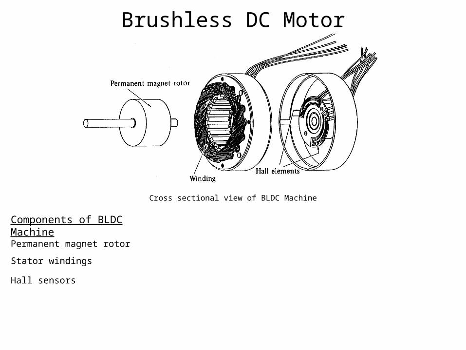
Brushless DC Motor
Cross sectional view of BLDC Machine
Components of BLDC Machine
Permanent magnet rotor
Hall sensors
Stator windings
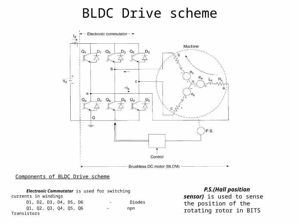
BLDC Drive scheme
Electronic Commutator is used for switching currents in windings
D1, D2, D3, D4, D5, D6 - Diodes Q1, Q2, Q3, Q4, Q5, Q6 - npn Transistors
P.S.(Hall position sensor) is used to sense the position of the rotating rotor in BITS
Components of BLDC Drive scheme
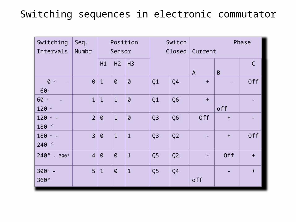
Switching sequences in electronic commutator
SwitchingIntervals
Seq.Numbr
Position Sensor
Switch Closed
Phase Current
H1 H2 H3 A B C
0 ° - 60° 0 1 0 0 Q1 Q4 + - Off
60 ° - 120 ° 1 1 1 0 Q1 Q6 + off -
120 ° - 180 ° 2 0 1 0 Q3 Q6 Off + -
180 ° - 240 ° 3 0 1 1 Q3 Q2 - + Off
240° - 300° 4 0 0 1 Q5 Q2 - Off +
300° - 360° 5 1 0 1 Q5 Q4 off - +
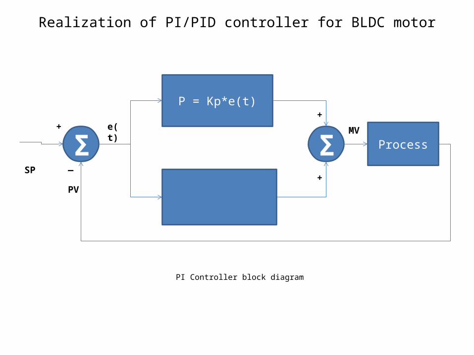
Realization of PI/PID controller for BLDC motor
P = Kp*e(t)
Σ Σ Process
e(t)
PV
SP —
++
+
MV
PI Controller block diagram
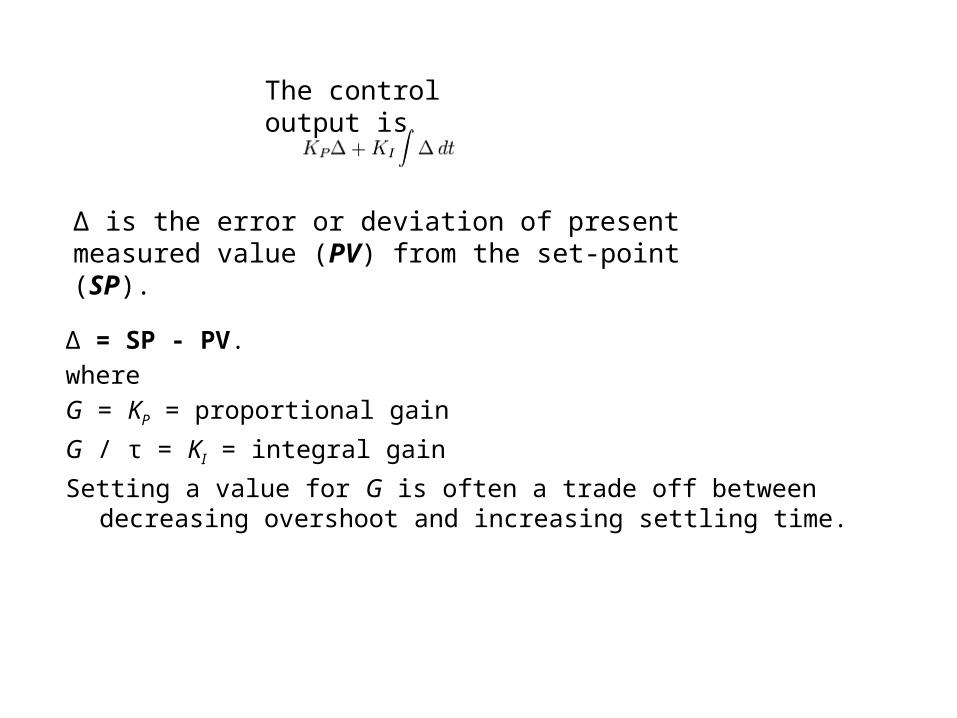
Δ = SP - PV.whereG = KP = proportional gain
G / τ = KI = integral gain
Setting a value for G is often a trade off between decreasing overshoot and increasing settling time.
The control output is
Δ is the error or deviation of present measured value (PV) from the set-point (SP).
Advantages & Disadvantages of PI Controller
• The integral term in a PI controller causes the steady-state error to reduce to zero, which is not the case for proportional-only control in general.
• The lack of derivative action may make the system more steady in the steady state in the case of noisy data. This is because derivative action is more sensitive to higher-frequency terms in the inputs.
• Without derivative action, a PI-controlled system is less responsive to real (non-noise) and relatively fast alterations in state and so the system will be slower to reach setpoint and slower to respond to perturbations than a well-tuned PID system may be.
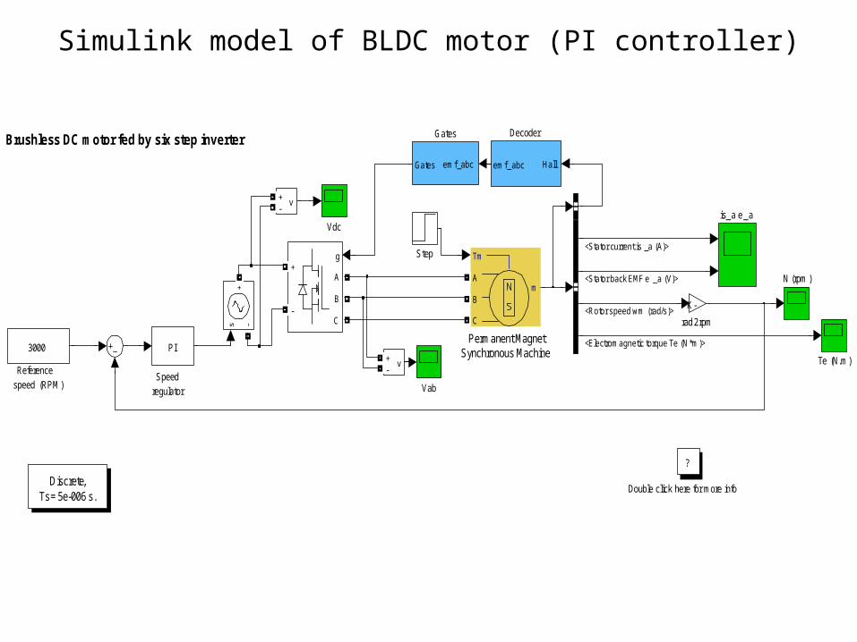
Simulink model of BLDC motor (PI controller)
Brushless DC motor fed by six step inverter
Speed regulator
Reference speed (RPM)
rad2rpm
K-
Discrete,Ts = 5e-006 s.
is_a e_a
PI
v+-
v+-
Vdc
Vab
g
A
B
C
+
-
Te (N.m)
Step
Permanent MagnetSynchronous Machine
Tm
mA
B
C
N (rpm )
Gates
emf_abc Gates
Double click here for more info
?
Decoder
Hall emf _abc
3000
<Stator current is _a (A)>
<Stator back EMF e _a (V)>
<Rotor speed wm (rad/s)>
<Electromagnetic torque Te (N*m)>
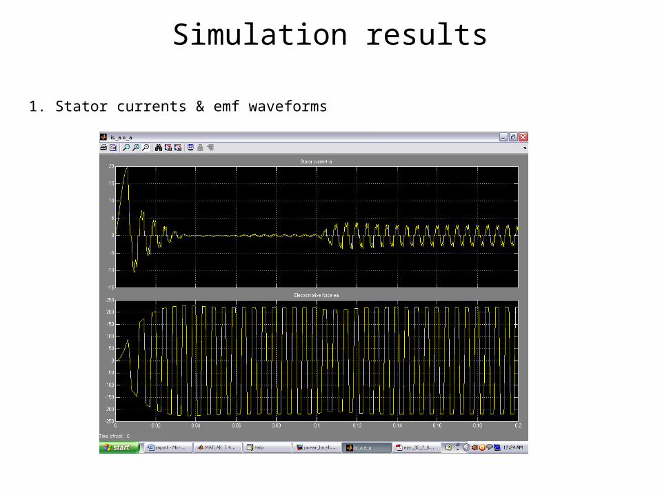
Simulation results
1. Stator currents & emf waveforms
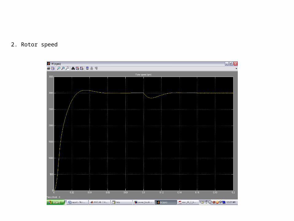
2. Rotor speed
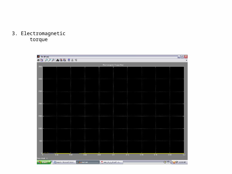
3. Electromagnetic torque
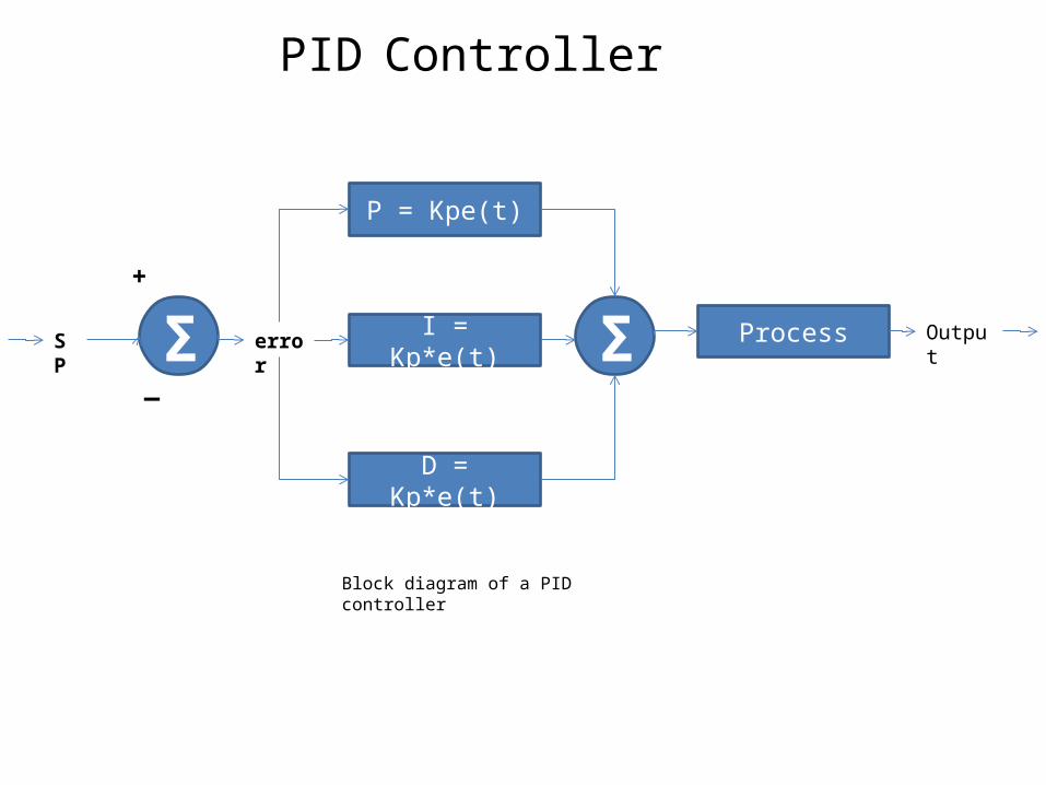
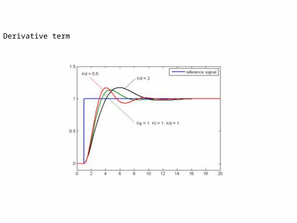
PID Controller
Process
D = Kp*e(t)
I = Kp*e(t)
P = Kpe(t)
Σ Σerror OutputSP
—
+
Block diagram of a PID controller
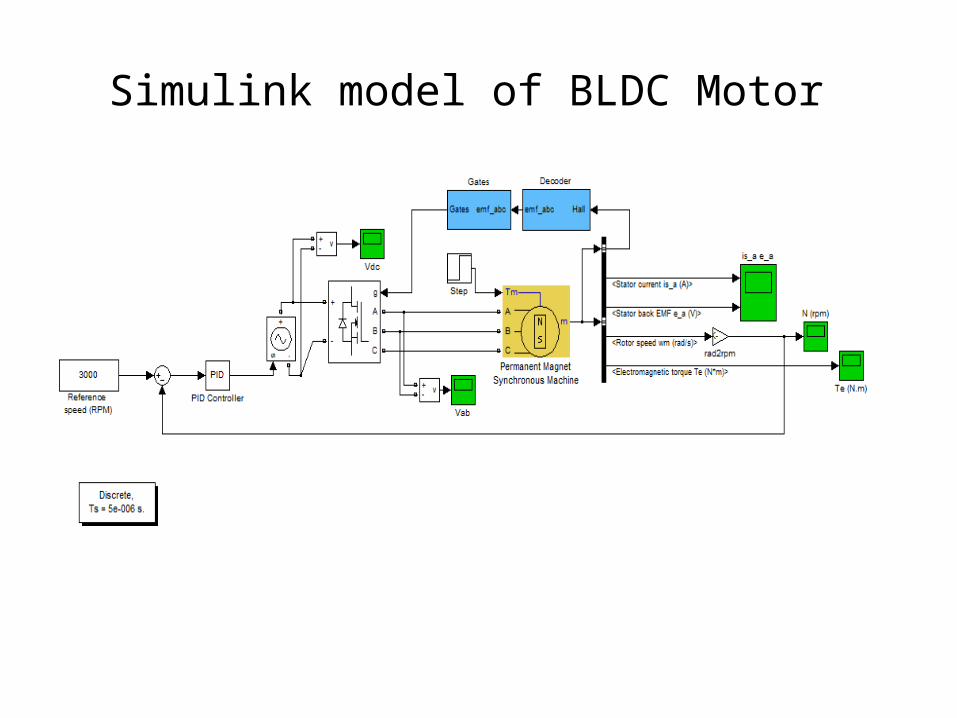
Simulink model of BLDC Motor