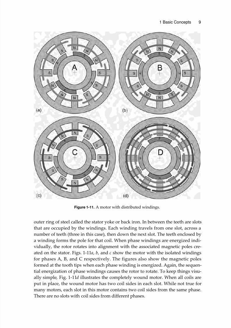
1 Basic Concepts This chapter develops a number of basic motor concepts in a way that appeals to your intuition. In doing so, the concepts are more likely to make sense, especially when these concepts are used for motor design in later chapters. Many of the con- cepts presented here apply to most motor types since all motors are constructed of similar materials and all produce the same o utput, namely torque. 1.1 Scope This text covers the analysis and design of rotational brushless permanent magnet !M" motors. #rushless $%, !M synchronous, and !M step motors are all brush- less permanent magnet motors. These specific motor types evolved over time to satisfy different application niches, but their operating principles are essentially identical. Thus, the material presented in this text is applicable to all three of these motor types, with particular emphasis given to brushless $% and !M synchronous motors. To put these motor types into perspective, it is useful to show where they fit in the overall classification of electric motors as shown in Fig. 1-1. The other motors shown in the figure are not considered in this text. Their operating principles can be found in a number of o ther texts. #rushless $% motors are typically characteri&ed as having a trape&oidal back electromotive force i.e. , back 'M(" and are typically driven by rectangular pulse currents. This mimics the operation of brush $% motor s. (rom this perspective, the name )brushless $%* fits even though it is an +% motor. !M synchronous motors differ from brushless $% motors in that they typically have a sinusoidal back 'M( and are driven by sinusoidal currents. tep motors in general have high pole counts and therefore require many periods of excitation for each shaft revolution. 'ven though they can be driven like other synchronous motors, they are typically drive n wit h current pul ses. te p motors ar e typica lly use d in low cos t, hi gh volume, position control applications where the cost of position feedback cannot be ustified. 1.2 Shape The most common moto r shape is cyl indri cal as shown in Fig. 1-2. This motor shape and all others contain two primary parts. The nonmoving or stationary part is called the stator. The moving or rotating part is called the rotor. In most cyl- 1