Embed Size (px)
Citation preview

7/29/2019 Research Paper RoF Network Final3
http://slidepdf.com/reader/full/research-paper-rof-network-final3 1/5
1
DWDM Based System for Optical
Generation and Transmission of Impulse
Radio UWB SignalsAffan Hasan Khan, Omer Khalid, Ateeq Mumtaz, Dr. M. Khawar Islam
Faculty of Telecommunications and Information Engineering
University of Engineering and Technology, Taxila, Pakistan
Abstract— This paper puts forward a simple technique for
generation of Impulse Radio Ultra-wideband pulses in optical
domain using an optical delay line, optical bias and an optical
subtractor. We transmit the data for 32 users across a 1 km
optical fiber link using Dense Wavelength Division Multiplexing. Moreover, we analyze the relationship between the
input data rate and signal bandwidth and also study the effect of
pulse width on the bandwidth of a signal. This paper depicts our
research and efforts in UWB-over-fiber technology.
Index Terms — DWDM, Impulse Radio, Optical
Differentiator, Ultra-wideband (UWB) over fiber
I INTRODUCTION
Ultra-wideband is an up-and-coming technology in wireless
communication that has the potential to provide high data
rate broadband wireless access. Though it is an emergingtechnology at present, the concept is not new at all. The
history of using UWB for wireless communication goes
back to early 1900s when Marconi used UWB pulses in his
spark-gap radio transmitter to transmit Morse code
sequences. The prominent qualities of UWB attracting
attention of researchers from around the globe are its low
complexity, low cost, reduced power consumption and
increased data rate. The mere limitation of UWB is its short
range which can be overcome by the use of Optical Fibers
carrying signals from the head-end to user premises. This
technology is commonly referred to as UWB-over-fiber.
The generation of UWB pulses has always been a challengebecause the wide bandwidth requires the signal to be
considerably narrow in the time domain. Moreover, to fully
exploit the advantages of UWB, there is a need for optical
generation of UWB pulses to avoid the use of high cost
electrical components required to produce such narrow
signals and to exceed the speed limitations offered by the
electrical components. Numerous solutions have been
proposed in the past demonstrating all-optical generation of
UWB pulses. Recent approaches include the use of cross
phase modulation[1], cross-gain modulation in a
semiconductor optical amplifier (SOA) [2], intensity
modulator to generate polarity switchable UWB pulses [3],
LiNbO3 Intensity modulator using the transfer function’s
wavelength dependant characteristics [4] and the use of Phase Modulator and AMZI to generate UWB pulses [5].
The problem associated with [1] and [2] is that they require
two laser sources resulting in increased system complexity.
In [3] and [4], the generation is limited to a single UWB
pulse which confines the use of this technique to a limited
number of applications. Also, the requirement of two
wavelengths in [4] renders the system expensive and
complicated. [5] requires two Asymmetric Mach-Zehnder
interferometers (AMZIs) to be cascaded which causes the design to face stability issue.
In this paper we put forward a technique to generate UWB
signals in optical domain and demonstrate a DWDM baseddistribution mechanism. A Mach-Zehnder modulator is
used to intensity modulate electrical Gaussian pulses. An
optical delay line followed by a subtractor is used to
differentiate the optical Gaussian pulse and thus Ultra-
wideband monocycle pulses are generated. Owing to the
use of optical components only, this technique results in an
ultrafast optical pulse source.
II. OPERATING PRINCIPLE
Figure 1 shows the schematics of the proposed design. The
electrical Gaussian pulses are generated from the incoming
data by the help of a Gaussian pulse generator. These
electrical pulses modulate a Mach-Zehnder modulator andoptical Gaussian pulses are produced. The Gaussian pulse
can be expressed as:
√ (
) (1)
7/29/2019 Research Paper RoF Network Final3
http://slidepdf.com/reader/full/research-paper-rof-network-final3 2/5
2
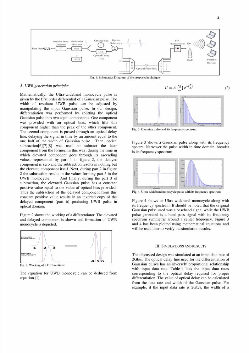
Fig. 1: Schematics Diagram of the proposed technique
A. UWB generation principle:
Mathematically, the Ultra-wideband monocycle pulse is
given by the first order differential of a Gaussian pulse. The
width of resultant UWB pulse can be adjusted by
manipulating the input Gaussian pulse. In our design,
differentiation was performed by splitting the optical
Gaussian pulse into two equal components. One component
was provided with an optical bias, which lifts thiscomponent higher than the peak of the other component.
The second component is passed through an optical delay
line, delaying the signal in time by an amount equal to the
one half of the width of Gaussian pulse. Then, optical
subtraction[6][7][8] was used to subtract the later
component from the former. In this way, during the time in
which elevated component goes through its ascending
values, represented by part 1 in figure 2, the delayed
component is zero and the subtraction results in nothing but
the elevated component itself. Next, during part 2 in figure
2 the subtraction results in the values forming part 5 in the
UWB monocycle. And finally, during the part 3 of
subtraction, the elevated Gaussian pulse has a constant
positive value equal to the value of optical bias provided.
Thus the subtraction of the delayed component from this
constant positive value results in an inverted copy of the
delayed component (part 6) producing UWB pulse in
optical domain.
Figure 2 shows the working of a differentiator. The elevated
and delayed component is shown and formation of UWB
monocycle is depicted.
Fig. 2: Working of a Differentiator
The equation for UWB monocycle can be deduced from
equation (1):
(2)
Fig. 3: Gaussian pulse and its frequency spectrum
Figure 3 shows a Gaussian pulse along with its frequency
spectra. Narrower the pulse width in time domain, broader
is its frequency spectrum.
Fig. 4: Ultra-wideband monocycle pulse with its frequency spectrum
Figure 4 shows an Ultra-wideband monocycle along with
its frequency spectrum. It should be noted that the original
Gaussian pulse used was a baseband signal while the UWB
pulse generated is a band-pass signal with its frequency
spectrum symmetric around a center frequency. Figure 3
and 4 has been plotted using mathematical equations and
will be used later to verify the simulation results.
III. SIMULATIONS AND RESULTS
The discussed design was simulated at an input data rate of
2Gb/s. The optical delay line used for the differentiation of
Gaussian pulses has an inversely proportional relationship
with input data rate. Table-1 lists the input data rates
corresponding to the optical delay required for proper
differentiation. The value of optical delay can be calculated
from the data rate and width of the Gaussian pulse. For
example, if the input data rate is 2Gb/s, the width of a

7/29/2019 Research Paper RoF Network Final3
http://slidepdf.com/reader/full/research-paper-rof-network-final3 3/5
3
single bit comes out to be 1/(2*109) = 0.5 ns. So, if the
Gaussian pulses are configured to be 0.1 bit wide, the width
of the pulses in nanoseconds comes out to be 0.5*0.1 = 0.05
ns. Practically, due to limitations of the Gaussian pulse
generator, the actual width is twice this value i.e. 2*0.05 =
0.1 ns. Hence, at a data rate of 2 Gb/s, an optical delay line
of 0.05 ns (one half of Gaussian pulse width) is required for
proper differentiation. From these calculations we canderive an equation to calculate the value of optical delay
line from the data rate and pulse width.
UWB pulses generated at 2Gb/s and the corresponding
frequency spectrum is shown in figure 5 and 6 respectively.
The used modulation technique was On-Off keying.
TABLE-1DATA RATES CORRESPONDING TO THE REQUIRED OPTICAL
DELAY
Sr. No. Data Rate(Gb/s)
Optical Delay(ns)
1. 0.5 0.2
2. 1 0.1
3. 2 0.05
4. 4 0.025
Fig. 5: UWB monocycle generated at 2 Gb/s.
Fig. 6: Frequency spectrum of UWB monocycle at 2Gb/s. The spectrum is
centered at 5 Ghz and has a bandwidth of 6 GHz at -10dbm.
For comparison, the simulation has also been performed at
a data rate of 1Gb/s. With the data rate reduced to one half,
the inverse proportional relationship dictates us to double
the optical delay offered. The required optical delay comes
out to be 0.05*2 = 0.1ns which can be verified from table.
1. Figure 7 and 8 shows the UWB monocycle produced and
the corresponding frequency spectrum respectively, at an
input data rate of 1Gb/s.
Fig. 7: UWB monocycle generated at 1 Gb/s. (Twice the pulse width at 2
Gb/s)
Fig. 8: Frequency spectrum of UWB monocycle at 1Gb/s. The spectrum iscentered at 2 Ghz and has a bandwidth of 3 GHz at -10dbm.
The width of the UWB monocycle in figure 5 is 0.2 ns
while it is 0.4 ns in figure 7. These widths are twice the
widths of the Gaussian pulses used to generate them. With
the data rate reduced to one half, the width of the pulse in
time domain in doubled. Intuitively, this should have an
effect on the corresponding bandwidths of the pulses as
well. From figure 6 and 8 we can derive conclusions that
there is a direct proportionality between the input data rate
and UWB pulse bandwidth. Doubling the data rate doubles
the bandwidth. Figure 9 shows this relationship in the form
a graph for two different values of Gaussian pulse widthused for UWB monocycle generation.

7/29/2019 Research Paper RoF Network Final3
http://slidepdf.com/reader/full/research-paper-rof-network-final3 4/5
4
Fig. 9: Relationship between input data rate and bandwidth for two
different values of Gaussian pulse width used.
From the graph, it is clear that increasing the width of
Gaussian pulse used, reduces the bandwidth of output UWB
pulse, while the directly proportional relationship between
input data rate and bandwidth stays the same. This is in
compliance with the fact that, shorter the pulses in time
domain, broader are their frequency spectra.
Figure 10 shows the output of Dense Wavelength Division
Multiplexing. The UWB pulses carrying the data of 32
different users were multiplexed using a frequency spacing
of 100 GHz or a wavelength spacing of 0.8 nm.
Fig. 10: 32 Dense Wavelength Division Multiplexed channels
Finally, figure 11 shows the shape of the signal for one user
after travelling over a 1 km optical fiber link with an
attenuation of 0.2 db/km and dispersion of 16.75 ps/nm/km.
The Signal was received using a PIN photo diode.
Fig. 11: Shape of the UWB monocycle received after passing through 1
Km of optical fiber links
IV. CONCLUSIONS
A simple technique for optical generation of Impulse radio
UWB pulses was described along with the mechanism to
transmit the data of 32 users over an optical fiber link using
Dense Wavelength Division Multiplexing. We found that
the bandwidth available is directly proportional to the input
data rate. Also, we figured out that we can increase thebandwidth by reducing the width of our UWB pulse. The
use of all-optical generator for UWB pulses allows to
exceed the limitations of electrical components and high
data rates can be achieved.
REFERENCES
[1] F. Zeng, Q. Wang and J. Yao, “All-optical UWB impulse generation
based on cross-phase modulation and frequency discrimination”,
ELECTRONICS LETTERS, 18th January 2007, Vol. 43 No. 2
[2] Wang, Q., Zeng, F., Blais, S., and Yao, J., “Optical ultrawidebandmonocycle pulse generation based on cross-gain modulation in a
semiconductor optical amplifier”, Opt. Lett., 2006, 31, pp. 3083 – 3085
[3 Q. Wang and J. Yao, "UWB doublet generation using nonlinearly-biased electro-optic intensity modulator," Electron. Lett. 42, (2006), 1304--
1305
[4] J. Q. Li, S. N. Fu, K. Xu, J. Wu, J. T. Lin, M. Tang, and P. Shum,
"Photonic ultrawideband monocycle pulse generation using a single
electro-optic modulator," Opt. Lett., vol. 33, no. 3, pp. 288-290, Feb.
2008Opt. Lett. 33, 288 (2008).[5] S. Pan and J. P. Yao: “Switchable UWB pulse generation using a phase
modulator and a reconfigurable asymmetric Mach-Zehnder
interferometer”, Opt. Lett. 34, 160 (2009).[6] K. Patorski, “Subtraction and addition of optical signals using a
double-grating shearing interferometer,” Optics Communications
Volume 29, Issue 1, April 1979, Pages 13-16[7] S. J. S. Bradshaw and P. J. C. Child, “Optical data addition and
subtraction,” Optical and Quantum Electronics, Volume 1, Number 1, 45-
48.[8] Kumshilin, A.A. Raita, E. Silvennoinen, R. Jaaskelainen, T., “Optical
Subtraction Using Double Phase Conjugate Mirror in a PhotorefractiveWaveguide,” Lasers and Electro-optics Europe, 1996. CLEO/Europe. 70-
70.

7/29/2019 Research Paper RoF Network Final3
http://slidepdf.com/reader/full/research-paper-rof-network-final3 5/5
5