Embed Size (px)
Citation preview

FLORIDA DEPTARTMENT OF TRANSPORTATION REQUEST FOR INFORMATION (RFI)*
RFI-DOT-14/15-9038-RC RPFD
The Department of Transportation, ITS Program of the Traffic Engineering and Operations Office, is requesting the following information from prospective vendors about the commodities and/or contractual services described below. Description of commodities/contractual services:
Copper and optical Layer 2 & 3 Ethernet technologies employing Multi-Protocol Label Switching (MPLS) technology as a means for transporting packet data over a Wide Area Network (WAN).
Specific Information Requested: Please refer to attached document, Exhibit A
Timeline:
1. Question & Answer Period Vendors may submit questions to FDOT until 5:00PM (DST) on April 9, 2015, at which point no other questions will be considered by FDOT. 2. FDOT Response FDOT will respond to vendors’ questions by 5:00PM (DST) on April 30, 2015, at which point the Q&A period will close. 3. Vendors’ Response Respondents must submit any/all information (to provide completed responses to the FDOT for this RFI) by 5:00PM (DST) on May 21, 2015.
Questions and Responses should be E-mailed to:
[email protected] and [email protected] Contact for this RFI:
If you have concerns or need clarification, contact [email protected] *NOTE: Responses to this Request for Information (RFI) will be reviewed by the agency for informational purposes, and will not be considered as offers to be accepted by the agency to form a binding contract. Advertisement of any subsequent competitive solicitation that may result from this RFI will be posted on the Florida Vendor Bid System.
Page 1 RFI-DOT-14/15-9038-RC

EXHIBITA
Florida Department of Transportation
Statewide Telecommunications Network
Next-Generation Network Upgrade Project
Request for Information on Networking Technology
MULTI-PROTOCOL LABEL SWITCHING
RFI Prepared by:
Florida Department of Transportation

Page 2 of 18
ContentsStatewide ITS Network Upgrade – Multi‐Protocol Label Switching RFI ...................................................................3
1. Description ............................................................................................................................ 3 1.1 Background ...........................................................................................................................................3
1.1.1 Existing Applications .....................................................................................................................4
1.1.2 Current FDOT ITS Statewide Network; ITS WAN, SMS .................................................................5
1.1.3 Limitations and Constraints ..........................................................................................................8
1.2 Requirements .......................................................................................................................................8
1.2.1 Assumptions .............................................................................................................................. 10
1.3 Upgrade Scenarios ............................................................................................................................. 10
1.3.1 Upgrade Scenario #1 – The Florida Turnpike Upgrade .............................................................. 10
1.3.2 Upgrade Scenario #2 ‐ Upgrade all Hub Sites and Key Application Sites .................................. 14
2. Questions for Respondents .......................................................................................................................... 16
3. Acronyms ...................................................................................................................................................... 17

Page 3 of 18
StatewideITSNetworkUpgrade–Multi‐ProtocolLabelSwitchingRFI
1. DescriptionThe Florida Department of Transportation (FDOT), in support of Intelligent Transportation Systems (ITS), is
seeking information to implement a strategy to upgrade the existing FDOT Statewide Telecommunications
Network (STN) to a “next generation” statewide ITS network. This strategy is expected to be implemented in a
phased approach, which will not encompass the entire state at once. The network upgrades will be
implemented in stages as funding becomes available over several years’ time. This RFI is addressing the
utilization of Multi‐Protocol Label Switching (MPLS) technology. A successful RFI response will involve only
MPLS as a design consideration.
The two goals of this RFI are to determine if MPLS is the best strategy for the FDOT, and also to determine the
type of phasing plan that will provide the greatest benefit to the FDOT.
The Statewide ITS network provides the backbone for Intelligent Transportation Systems equipment, such as
traffic counters, traffic signaling, traffic cameras, dynamic message signs, highway advisory radio, and other
such ITS devices. Respondents should note that this network’s purpose is not for telephony, or
placing/receiving phone calls.
For this RFI, the FDOT is looking for a strategy from a single respondent covering switching and routing
technology where both microwave and fiber optics are used as transport. The FDOT realizes that multiple
equipment vendors/manufacturers may be required to build a complex system such as this. The FDOT desires
to know about strategic alliances that may be needed, and how transport (microwave and fiber optics)
offerings can be integrated into the proposed strategy.
Capital Expense (CAPEX) and Operational Expense (OPEX) budget estimates, including equipment, optional
features, software licenses, element managers, spares inventory and ongoing maintenance costs should be
included in your response.
Respondents should also include detailed technical information regarding interconnects, configuration
samples, information regarding complexities of adding services/circuits, maintenance, and troubleshooting
procedures. See the Questions in Section 2 of this document for specific technical questions the FDOT has
regarding an MPLS strategy for our Next Generation Network (NGN).
It is the aim of FDOT to collapse three networks, the ITS WAN, the SMS, and the Turnpike Microwave System
into a single, cohesive Statewide ITS Backbone which will create a redundant and resilient backbone to support
today’s and future applications and traffic between the regional data centers.
A complete RFI response should include design responses for each of the scenarios in section 1.3, and answer
all questions listed in Section 2.
1.1 BackgroundThe FDOT operates a statewide ITS network, comprised of two transports; a statewide microwave system
(SMS), and a fiber optic network (ITS WAN). Where fiber currently exists, it is the primary transport for most
ITS traffic in the system statewide. Where there is no fiber, and in the event of multiple catastrophic fiber
outages, traffic is transported over the SMS.

Page 4 of 18
The primary mission of the statewide ITS network is to enable center‐to‐center (C2C) communications and
interoperability between the FDOT districts' transportation management systems software installed at the
FDOT districts' Regional Transportation Management Centers (RTMCs), and to share traffic management data
and digital closed‐circuit television (CCTV) traffic‐camera video between the FDOT districts and other users. It
is important to note that the districts autonomously manage their own ITS networks within their respective
boundaries. The statewide ITS network transports data between the FDOT's districts, Florida’s Turnpike
Enterprise (FTE), other FDOT partners, and their respective RTMCs. There are additional applications whose
traffic rides on the STN backbone which are listed below.
1.1.1 ExistingApplicationsCenter to Center Applications
Traffic Camera Video Sunguide Sharing (C2C) FHP CAD Managed Lanes Tolling NOAA VAS Radio Applications
47MHz (Voted) FTE UHF Radio – Road Rangers ROIP FUTURE SARNET ROIP (JPS Raytheon NXU‐2A) UHF Future Radio Applications Field Data Network
RWIS Intra‐district data on the network Tolls Revenue Tolls SCADA FTE ITS FTE 4‐Digit Dialing Management
NetBoss PENSACOLA, TAMPA, LAKE CITY, PORT ORANGE Preside ITSWAN MGMT Tower infrastructure hard contacts 4‐Digit Dialing EOW Other Applications
SLERS FirstNet FCC Monitoring

Page 5 of 18
1.1.2 CurrentFDOTITSStatewideNetwork;ITSWAN,SMSThere are two sub‐systems, the Statewide Microwave System (SMS) and the Intelligent Transportation Systems
Wide Area Network (ITS WAN). There are currently two Network to Network Interfaces (NNIs) between these
two IP networks allowing management and other traffic to communicate between them.
The SMS is a legacy infrastructure comprised of 74 sites built upon 6 GHz time division multiplex (TDM)
microwave; specifically, the Harris DVM6‐45 and Constellation microwave radios. These radios provide a 45
Mbps backbone via 28 T1s. At certain key sites (“hub” sites) within the system, the microwave radios are
configured as terminals providing access to all 28 T1 circuits from each radio. At the remainder of the sites, the
radios are configured as repeaters and a maximum of up to 16 T1 circuits (in each direction) is available (some
sites have less). All T1 circuits are framed.
Two T1 circuits are dedicated statewide to a DACC/channel bank system that supports the FDOT’s 47 MHz
repeater system.
Two T1 circuits are dedicated statewide to a management IP network constructed using Nortel ASN routers
that transports SNMP, TL1 and other management traffic between the sites and the network management
systems. An additional T1 is dedicated statewide to a field data network utilizing the same Nortel ASN routers,
but in a different IP address space. The Field Data Network currently supports the FDOT’s RoIP system and
field‐based ITS equipment, including video.
In the 74‐site SMS, fourteen (14) sites are considered “hub” sites. These sites are equipped with a DS3
multiplexer, which aggregates the unallocated microwave T1 circuits into a fractional, channelized DS3 format
that is connected to the Ericsson Passport 15000 ATM switches. The ATM switches utilize this bandwidth to
provide Ethernet Virtual LAN Services (EVLS) circuits to the adjacent “hub” site(s) in the microwave network.
(See Figure 1.1.2‐2 and 1.1.2‐3 below). These EVLS circuits support both the field data network, as well as
District‐to‐District applications. It is the intent of the FDOT to pursue the upgrade of the SMS to a hybrid
Ethernet and TDM microwave transport strategy to provide native Ethernet connectivity.
In addition to the 74 SMS sites, there is a second microwave network, Florida Turnpike Microwave System
(FTMS) specific to the Florida Turnpike Enterprise. This network is comprised of 20 sites. This network is
strictly a TDM network with no Layer 2 or 3 devices. However; there are a total of 9 sites which are co‐located
with either the fiber optic ITS WAN and/or SMS sites. During the upgrade project, the Florida Turnpike
Microwave System will become part of the statewide ITS backbone.
While the fiber optic (ITS WAN) network is presently being built out, portions of the state are in operation on
the network; primarily, the Southern half of the peninsula. The ITS WAN transports are comprised of both
long‐haul optical CWDM SONET providing up to 2.5 gigabits/second bandwidth, and Layer 3 connectivity to the
RTMCs. Conversely, the Statewide Microwave System (SMS) is fully deployed across the state and provides ITS
WAN connectivity to key FDOT sites where fiber is not currently present.

Page 6 of 18
Figure 1.1.2‐1 ‐ Baseline View of Existing Network(s)
Figure 1.1.2‐2 – Typical “Key” Application Site

Page 7 of 18
Figure 1.1.2‐3 – Typical “Hub” Site
8006
8005DI-AC
DC OK
AC OK AC OK
47 - 63Hz EACH INPUT200 - 240 V~ 9.5A
100 - 240 V~ 16A
8005DI-AC
DC OK
AC OK AC OK
47 - 63Hz EACH INPUT200 - 240 V~ 9.5A
100 - 240 V~ 16A
Onli ne
8608SXE
T X
RX
1 2 3 4 5 6 871 2 3 4 5 6 7 8
Onli ne
8608SXE
T X
RX
1 2 3 4 5 6 871 2 3 4 5 6 7 8
Online
8648TXE10 /100 Link/Act 471 3 5 7 9 11 13 15 19 21 23 25 27 29 31 33 35 37 39 41 43 4517
2 484 6 8 10 12 14 16 20 22 24 26 28 30 32 34 36 38 40 42 44 4618
Figure 1.1.2‐4 – Hub Site with Fiber Optic availability

Page 8 of 18
1.1.3 LimitationsandConstraintsThe FDOT has made a considerable investment in the Statewide Microwave System, and wishes to leverage
these assets (real estate, towers, antennas, wave‐guide) as a means for providing redundancy for the fiber‐
optic ITS WAN. However, if the fiber‐optic WAN experiences an issue preventing the flow of network traffic,
potentially 2.5 gigabits/second (Gbps) will have to traverse a much slower 45 megabits/second (Mbps)
microwave link. As the next‐generation network will certainly have similar constraints (i.e.: a 10 Gbps fiber
backbone coupled with a 300‐400 Mbps microwave system), equipment features must be available to groom
traffic via class‐of‐service/quality‐of‐service, queue prioritization, and other traffic shaping methods.
Network infrastructure equipment (switches, routers, hubs, etc.) in both networks are obsolete, and end‐of‐
life.
The migration plan to a Next Generation Network (NGN) will be undertaken in stages, as funding becomes
available, and in key locations where the FDOT has particular business needs to meet.
Therefore, the FDOT seeks to obtain information from respondents about their specific technology offerings,
and how they may fit into this unique upgrade scenario.
The purpose of the RFI is to develop a path to the “Next Generation Network” which will combine overlapping
sites with a single WAN technology. The Next Generation Network shall leverage legacy TDM microwave sites
(until they are phased out), newly upgraded microwave sites (hybrid TDM and Ethernet) and long haul optical
technology to collapse the networks into a single cohesive network. The mission remains to support all existing
TDM and Ethernet / IP applications and future ones as well.
1.2 RequirementsThe strategy recommended by respondents for the Next Generation Network (NGN) must meet the following
requirements:
Intra‐domain IP multicast MUST be supported (multicast between next generation and legacy networks
must function correctly).
Multicast Source Discovery Protocol (MSDP) of inter‐domain PIM‐SM domains (multicast between next
generation and legacy networks must function correctly). Multicast traffic can be native via rendezvous
point(s), or tunneled from source to destination via a label or service identifier or Virtual Local Area
Network (VLAN), as long as traffic from a multicast source reaches its destination efficiently. See drawing
below.

Page 9 of 18
VLAN XYZ
MulticastSource
VLAN XYZ
MulticastDestination
Switch
RendezvousPoint
SwitchMulticast Source Network
VLAN XYZ
MPLS CloudServices Core
RendezvousPoint
DestinationNetwork
Layer 3
Layer 2
VLAN XYZ
Switch
Switch SwitchLayer 3
Figure 1.2‐1: Inter‐domain PIM‐SM
Support Transport T1 (TDM) circuits (i.e., pseudo‐wire) either inherent to the system or through use of
third‐party equipment interfaced to MPLS core.
Support Ethernet over T1 aggregation (TDM, either inherent to the system or through use of third‐party
equipment interfaced to MPLS core (e.g.: RAD Rici‐16).
MPLS core must communicate with two OSPF zero (0) domains (SMS management and ITS WAN), and one
OSPF ten (10) domain (data).
MPLS core must communicate with each of the districts who have their own OSPF areas (likely area zero
(0)), which currently connects to the ITS WAN backbone at Layer 3 (Center to Center).
Respondent/Manufacturer must specify routing protocols used between the legacy and next‐generation
networks (MPLS, OSPF, Static Route).
Minimum of eight COS/QOS queues for traffic grooming on next generation equipment.
Wire speed capabilities on all ports, all the time. FDOT does not want to deploy a piece of equipment at
any particular site that could become a bottleneck for traffic in the event that the particular site has to
process all traffic in the WAN; i.e.: catastrophic fiber outages in several locations force all WAN traffic to
traverse through a single site.

Page 10 of 18
Operations, Administration, and Management (OAM) between next generation and legacy networks
(Simple Network Management Protocol [SNMP]); ability to work with external respondents’ “manager of
managers” (MOM) applications (such as Harris NetBoss or MegaSys Telenium) for management. Specify
any additional applications/hardware/middleware to independently support all hardware devices in the
design. FDOT needs to understand what is needed to manage devices, and costs associated with
accomplishing a cohesive network management platform.
Isolated management network via labeling and/or VLAN.
Multi‐tenant capabilities (services and/or entities). The next‐generation network must be able to support
multiple Autonomous System (AS) domains.
Equipment currently available for sale, and support available for no less than seven years.
19‐inch two‐post rack mountable equipment
Redundant ‐48V DC power
1.2.1 AssumptionsThe current, legacy microwave system is TDM‐based NxT1. The new microwave system will be an Ethernet and
TDM hybrid system. The FDOT expects next generation microwave equipment to provide a minimum of 300
Mbps bandwidth per link (via single or multiple carriers), utilizing the existing tower infrastructure.
Construction of new or additional tower sites is not being contemplated.
To facilitate the continued use of the existing microwave infrastructure for some portions of the network for a
period of time, the FDOT is also looking for an Ethernet over TDM strategy that can bond multiple T1’s for
Ethernet connectivity. Some of these legacy sites may also have fiber connectivity which can be leveraged as
on/off ramps and for redundancy.
The FDOT is looking for equipment to provide a minimum of 10 Gbps bandwidth over our fiber optic access.
Approximate mileage between sites is provided so that respondents can recommend long‐haul optical
networking and/or regeneration equipment for furnishing a minimum of 10 Gbps bandwidth via fiber.
Management and alarming systems for next‐generation microwave radios, fiber optic equipment, network
equipment, and hard contact closure alarms for tower maintenance should function with IP/Ethernet OAM.
1.3 UpgradeScenarios1. Turnpike Section Upgrade – Complete upgrade
2. Upgrade all Hub Sites and “key application” sites within the SMS – Leverage fiber optic connectivity
where possible.
1.3.1 UpgradeScenario#1–TheFloridaTurnpikeUpgradeThe Florida Turnpike currently has a 20 site microwave system based on TDM technology. The Florida Turnpike
sites all have fiber optics in and out through them. Currently, ITS WAN has fiber strands allocated from
Turnpike fiber to assist ITS Central Office to complete their mission with respect to the statewide ITS network.
Respondents should consider all 20 Turnpike sites as key locations where fiber and microwave networks can be
leveraged for redundancy. Respondents should be aware that fiber is the primary path for all applications and
data center connections. In the event of a fiber outage, traffic will be shifted to a second or redundant fiber
path, if available, and then ultimately traffic engineered over the microwave as a last resort. The FDOT is
Page 11 of 18
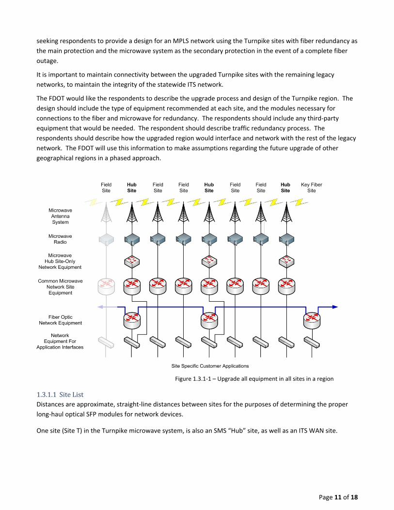
seeking respondents to provide a design for an MPLS network using the Turnpike sites with fiber redundancy as
the main protection and the microwave system as the secondary protection in the event of a complete fiber
outage.
It is important to maintain connectivity between the upgraded Turnpike sites with the remaining legacy
networks, to maintain the integrity of the statewide ITS network.
The FDOT would like the respondents to describe the upgrade process and design of the Turnpike region. The
design should include the type of equipment recommended at each site, and the modules necessary for
connections to the fiber and microwave for redundancy. The respondents should include any third‐party
equipment that would be needed. The respondent should describe traffic redundancy process. The
respondents should describe how the upgraded region would interface and network with the rest of the legacy
network. The FDOT will use this information to make assumptions regarding the future upgrade of other
geographical regions in a phased approach.
Figure 1.3.1‐1 – Upgrade all equipment in all sites in a region
1.3.1.1 SiteListDistances are approximate, straight‐line distances between sites for the purposes of determining the proper
long‐haul optical SFP modules for network devices.
One site (Site T) in the Turnpike microwave system, is also an SMS “Hub” site, as well as an ITS WAN site.

Site A Microwave Hub Site: No Site has Fiber Optics: Yes Distance from Site B: 18.5 miles Site B Site has Fiber Optics: Yes Distance from Site A: 18.5 miles Distance from Site C: 16.8 miles Site C Site has Fiber Optics: Yes Distance from Site B: 16.8 miles Distance from Site D: 4 miles Distance to Site E for Microwave Link: 12.36 miles Site D Site has Fiber Optics: Yes Site has no microwave tower Distance from Site C: 4 miles Distance from Site E: 8.36 miles Site E Site has Fiber Optics: Yes Distance from Site D: 8.36 miles Distance from Site F: 24.3 miles Distance to Site C for Microwave Link: 12.36 miles Site F Site has Fiber Optics: Yes Distance from Site E: 24.3 miles Distance from Site G: 22.1 miles Site G Site has Fiber Optics: No Distance from Site F: 22.1 miles Distance from Site H: 13.75 miles
Site H Site has Fiber Optics: Yes Distance from Site G: 13.75 miles Distance from Site I: 17.3 miles Site I Site has Fiber Optics: No Distance from Site H: 17.3 miles Distance from Site J: 19 miles Site J Site has Fiber Optics: Yes Distance from Site I: 19 miles Distance from Site K: 7.5 miles Site K Site has Fiber Optics: Yes Distance from Site J: 7.5 miles Distance from Site L: 10.9 miles Site L Site has Fiber Optics: Yes Distance from Site K: 10.9 miles Distance from Site M: 17.7 miles Site M Site has Fiber Optics: Yes Distance from Site L: 17.7 miles Distance from Site N: 15.7 miles Site N Site has Fiber Optics: Yes Distance from Site M: 15.7 miles Distance from Site O: 5.5 miles

Page 13 of 18
Site O Site has Fiber Optics: Yes Distance from Site N: 5.5 miles Distance from Site P: 12.4 miles Site P Site has Fiber Optics: Yes Distance from Site O: 12.4 miles Distance from Site Q: 14.3 miles Site Q Site has Fiber Optics: Yes Distance from Site P: 12.4 miles Distance from Site R: 8.28 miles
Site R Site has Fiber Optics: Yes Distance from Site Q: 8.28 miles Distance from Site S: 19.4 miles Site S Site has Fiber Optics: Yes Distance from Site R: 19.4 miles Distance from Site T: 18.5 miles Site T SMS Microwave Hub Site: Yes Site has Fiber Optics: Yes Distance from Site S: 18.5 miles

Page 14 of 18
Fiber
Fiber
Fiber
Fiber
MPLS
MPLS
MPLS
MPLS
FiberMPLS
1 GigE
6 GHz u‐wave
6 GHz u‐wave
6 GHz u‐wave
MPLS
6 GHz u‐wave
6 GHz u‐wave6 GHz u‐wave
EVLS Circuit ‐ up to 24 T1s
1 GigE
MPLS
Passport 15000
Passport 15000
Up to 2.5 Gbps SONET
CienaOM‐5200
CienaOM‐5200
Site A
Site B
Site C ...
Sites G & I ...
Site R
Site S
Site T
Figure 1.3.1.1‐1 – Depiction of Turnpike Microwave System Following Upgrade
1.3.2 UpgradeScenario#2‐UpgradeallHubSitesandKeyApplicationSitesIn this upgrade scenario, FDOT is looking for a proposed strategy(ies) to leverage the existing legacy microwave
system while deploying updated MPLS equipment to build a foundation for the next‐generation network.
It is the desire of the FDOT, in this scenario, to replace each of the Ericsson Passport 15000s located at the hub
sites with an MPLS product. The Ericsson Passport 15000’s interface to the legacy microwave system is via a
channelized, fractional DS3. The FDOT is requesting that the respondents provide options for leveraging the
available SMS bandwidth for the MPLS network. Note that the DS3 multiplexers can be eliminated if direct
access to the 24 channelized T1 circuits is desired.

Page 15 of 18
It is also the desire of the FDOT to replace legacy routers at “key” application sites (see Figure 1.1.1.1‐2) to
provide MPLS services at the site by leveraging the available capacity of the SMS. Key Application sites include
all sites that require intra‐network multicast capability. However, these locations do not have access to the full
28xT1 bandwidth of the microwave system; but, they may have access to the fiber optic network. A maximum
of 16 T1 circuits via the SMS, in each direction is available, 2‐3 T1 circuits are dedicated to the channel bank
system and 3 T1 circuits are dedicated to the legacy router network. These 5‐6 T1 circuits are shared with
other sites and therefore cannot be reallocated without upgrading all sites located between two hub sites. Of
the remaining 9‐10 T1 circuits, each of these T1s reallocated to provide transport to a “key” application site
comes from the T1 circuits connecting the hub sites. That is, if the capacity of the fractional, channelized DS3
between two hub sites is 24 T1 and 8 T1s are reallocated to serve a “key” application site located between the
two hub sites, the fractional, channelized DS3 capacity is reduced to 16 T1. Based upon the application
requirements, the bandwidth requirement at the “key” application sites are relatively low at this time (~
3Mbps), however, the flexibility of reallocating more T1s for transport is desired if a solution exists that does
not detract from the capacity between hub sites (i.e., MPLS traffic can efficiently and fully utilize both the hub‐
to‐hub route and the hub‐to‐key site‐to‐hub site route).
It is also desired to eliminate the legacy routers, if feasible, at the hub site. As the legacy routers are T1‐based,
this requires a strategy that will interface the MPLS product to T1 circuits from routers at the adjacent sites.
Finally, the FDOT desires options for transporting the TDM‐based traffic from the DACC / channel bank system
over the MPLS network.
Describe how your strategy can replace the Ericsson Passport 15000 ATM switches using the channelized
fractional DS3s as transport for MPLS traffic.
Describe how your MPLS strategy would integrate with legacy routers at the remaining SMS sites. Could the
routers at the hub sites be replaced with an MPLS product?
Describe how your strategy will differ between key application sites with physical access to the fiber optic
network, versus those key application sites without direct access to the fiber network.
The FDOT would like the Respondent to describe the upgrade process and design of specific sites throughout
the statewide network. The design should include the type of equipment recommended at each site, and the
modules necessary for connections to the fiber and microwave for redundancy. The respondents should
include any third‐party equipment that would be needed. The respondents should describe how the upgraded
region would interface and network with the rest of the legacy network. The FDOT will use this information to
make assumptions regarding the future upgrade of other key sites in the phased approach.

Page 16 of 18
Figure 1.3.2‐1 – Upgrade Key Application Sites
2. QuestionsforRespondentsInclude answers to questions by repeating the question, and the stating answer.
1. Does your strategy meet all the requirements listed in section 1.2? Respond to each bullet point in
section 1.2. Explain variances or work‐arounds for equipment that does/will not meet the listed
requirements.
2. For the four different site types (hub site, legacy remote site, key application site, any site type with co‐
located fiber optic access) – provide a line item equipment configuration.
3. In budget estimates, provide any equipment and/or software/license costs (build‐out, tiered) for the
network element manager.
4. How does your strategy route traffic between MPLS domains and an OSPF domain(s)?
5. With regard to Upgrade Scenario 2: Describe how your strategy can replace the Ericsson Passport
15000 ATM switches using the channelized fractional DS3s as transport for MPLS traffic.
6. Describe the throughput the FDOT should expect from a 24‐T1 transport of MPLS traffic.
7. What is the minimum quantity of T1s needed to support MPLS traffic for a “key” application site with a
3 Mbps throughput requirement?
8. With regard to Upgrade Scenario 2: Describe how your MPLS strategy would integrate with legacy
routers at the remaining SMS sites. Could the routers at the hub sites be replaced with an MPLS
product?

Page 17 of 18
9. Could the routers at the “key” application sites be replaced with an MPLS product?
10. Do your products support end‐to‐end payload encryption? Please describe any encryption capabilities
of your products.
11. What are the advantages and disadvantages to deploying a MPLS strategy instead of maintaining an all
Layer‐3 network?
12. What are the advantages and disadvantages to deploying a MPLS strategy instead of deploying a Layer
2 Shortest Path Bridging (SPB) strategy, or staying with the current Layer 3 OSPF design?
3. AcronymsList of acronyms used within this document:
RFI – Request for Information
FDOT – Florida Department of Transportation
FTE – Florida’s Turnpike Enterprise
ITS – Intelligent Transportation Systems
SMS – Statewide Microwave System
STN – Statewide Telecommunications Network
ITS WAN – Intelligent Transportation Systems Wide Area Network
MPLS – Multi‐Protocol Label Switching
SPB – Shortest Path Bridging
LAN – Local Area Network
NMS – Network Management System
OAM – Operations, Administration & Management
MOM – Manager of Managers
NEM – Network Element Manager
OSPF – Open Shortest Path First
PIM – Protocol‐Independent Multicast
PIM‐SM – Protocol‐Independent Multicast Sparse Mode
RP – Rendezvous Point
EVLS – Ethernet Virtual LAN Service
ISIS – Intermediate System to Intermediate System
ISID – ISIS Service Identifier
VLAN – Virtual Local Area Network
ATM – Asynchronous Transfer Mode
TDM – Time Division Multiplexed
RF – Radio Frequency
SLERS – Statewide Law Enforcement Radio System
RoIP – Radio over Internet Protocol
EOW – Engineering Order Wire
FCC – Federal Communications Commission
FHP CAD – Florida Highway Patrol Computer Aided Dispatch
NOAA – National Oceanographic and Atmospheric Administration

Page 18 of 18
VAS – Video Aggregation Service
CWDM – Coarse Wave Division Multiplexed
DWDM – Dense Wave Division Multiplexed
SFP – Small Form‐factor Pluggable