Embed Size (px)
Citation preview

REPORT DOCUMENTATION PAGE I wiri» imuuw ,t miwic— to wm i *OM»OW
y*aw? ;a»i««y» of "»«onwniöo . to *»«*M«*to» ^iiiimmi*,
AFRL-SR-BL-TR-99- ~i 1. AOINCY UM ONLT (UM OMMj 2. MPORT OATI
2/12/99 "■ HSI ^/oW^Wflfts 4. mu ANO suimu Active Flow Control on Hurley's Free-Streamline Airfoil and Delta
«.AUTMORtS) Israel Wygnanski/Erdogan Madenci
7. KJVOMMN4 ORGANIZATION NAMI(S) ANO AOOMSsTuT Aerospace and Mechanical Engineering The College of Engineering and Mines The University of Arizona Tucson, Arizona 85721
ft. SPONSORVM/MONITORING AOXNCY NAMI(S) ANO AOORISSMsT
AFOSR/NA 801 Randolph St. Room 732 Arlington, VA 22203-1977
11. SUmiMfNTARY MOTtT
5. 'UNMM NUMSIRS
F49620-98-1-0298
ft. MWCKMM« OHOANOATION WORT NUftNMR
lt. SPOW0RW0/ MONTTOIÜNÖ* A4UNCY RtPQRT MURMUR
12«. OlSTRRMJTKM/AVAAARfljTY STATMMNT
Approved for Public Release Distribution is Unlimited
13a. OttTRRMjTKM COM
13. ARSTRACT (Mvamum 200 worm
This was a joint effort by The University of Arizona (UA) and Arizona State University (ASU). The work
was directed toward the application of active flow control to a free-streamline airfoil whose structural vibra-
tions were integrated into the control strategy. The Phase I accomplishments reported here demonstrate that
efficient free-shear-layer control is possible and the low drag of the free-streamline airfoil is a reality.
1«. SURJICT TIMMS is. NUMua or »AOIS
20 liMKI COM
17. SICUMTV CLASSIFICATION OtfUPORT
UNCLASSIFIED
IS. SICUMTY CLASSIFICATION OP THIS •AOI
UNCLASSIFIED
it. sicumTY OASSincAnoN OP ARSTRACT
UNCLASSIFIED
20, UMTTATION Of ARSTRACT
UNLIMITED
NSN 7540-01-J90-5300 §vtäzn r&C-:-~'K\''tnT!T> H Standard Porm 29t (««v. 2-89)

AFOSR CONTRACT F49620-98-1-0298 BAA98-02: AERO-STRUCTURAL INTERACTION AND CONTROL
PHASE I FINAL REPORT
On
ACTIVE FLOW CONTROL ON HURLEY'S FREE-STREAMLINE AIRFOIL AND DELTA WING
By
ISRAEL WYGNANSKI and ERDOGAN MADENCI Aerospace and Mechanical Engineering
University of Arizona Tucson AZ 85721
WILLIAM SARIC and HELEN REED Mechanical and Aerospace Engineering
Arizona State University Tempe AZ 85287-6106 KA
CO CD
Submitted to: Qg) Dr. Brian Saunders ~1 CO
Air Force Office of Scientific Research ^0 ^s 110 Duncan Ave. Ste B115 g*\
Boiling AFB, DC 20332-0001 ^T CO <
o Of
to o
f=2*5.

UA/ASU BAA98-2 Phase 1 Final Report
ABSTRACT
This was a joint effort by The University of Arizona (UA) and Arizona State University (ASU). The work
was directed toward the application of active flow control to a free-streamline airfoil whose structural vibra-
tions were integrated into the control strategy. The Phase I accomplishments reported here demonstrate that
efficient free-shear-layer control is possible and the low drag of the free-streamline airfoil is a reality.
1 RESEARCH GOALS
1.1 Introduction
Slender delta wings rely on reattached vortices to provide the necessary lift at low speeds and high angles of
attack. Without some form of control, when the angle of attack exceeds a certain threshold value on an or-
dinary delta wing, the vortex breaks down and lifts off the surface (Fig. la). This process results in a loss of
lift and an abrupt increase in drag. Many attempts, therefore, have been made (e.g., vortex flaps) to eliminate
vortex breakdown or at least to delay it. When periodic excitation was provided at the leading edge of this
delta planform, the vortex did not separate from the surface; the location of the reattachment line was de-
tected to remain parallel to the leading edge (Fig. lb). One may extrapolate the results obtained for the
"generic-flap" (Nishri et al. 1998) and the swept-back wing (Naveh et al. 1998) to a finite-wing planform.
They suggested that periodic forcing applied to a delta wing over which the flow was separated should cause
reattachment scaling with the dimensionless frequency F4'3D = fXJUx,, where Xa is the distance between
the leading-edge and the reattachment location normal to the leading edge,/is the forcing frequency, and
UN = UxfiosA is the normal component of velocity. Although this assumption appeared to be tenuous (it
was based on a transformation relying on an infinitely yawed wing section), it agreed with experiment in the
vicinity of the apex or the wing tip. Thus, the reattachment line on the wing surface was parallel to the lead-
ing edge except near the apex (Fig. lb). The result was similar to the flow visualization carried out on the
yawed wing.
The free-streamline airfoil proposed by Hurley (1961) is particularly attractive in its possible application to
slender delta wings in that it may capture the vortex between the main element and the upstream facing flap
(Fig. 2) providing an even larger lift than was hitherto possible with just periodic blowing. Other direct ap-
plications to uncrewed aerial vehicles (UAVs), low-speed flight of transonic and supersonic aircraft, and
control of complicated inlet flows are also implied and straightforward.
1.2 Accomplishments during Phase I
During Phase I of this proposal, we verified the feasibility of using the free-streamline airfoil as a high-lift
device and demonstrated the ability to calculate the flowfield and the structural vibrations. The proposed
control strategies worked and the agreement between measurements and computations was very good.

UA/ASU BAA98-2 Phase 1Final Report 3
Control of the flow over Hurley's free streamline airfoil
We first repeated the experiment of Hurley on a similar configuration (Fig. 3). The geometrical parameters
include the chord c, the flap angle T, the flap length KC, the angle of incidence of the main element a, and the
slot location. The flow parameters include the chord Reynolds number Re, those associated with the control
implemented on the flap (steady blowing amplitude Cya, periodic blowing rms amplitude <c/j2>, and dimen-
sionless periodic blowing frequency F2+), and those associated with the flaperon implemented on the leading
edge of the main element (periodic frequency Fj+ and periodic rms amplitude <cM]>).
As mentioned in the Introduction above, previous research has shown that the normal-to-the-leading-edge
component contains the relevant physics. The slot in the present experiment was moved to enable the oscil-
lations and the steady blowing to emanate from the gap between the circular cylinder and the upper surface
(Fig. 3). The basic airfoil provided a maximum lift of 1.4 at an incidence of 20° (Fig. 4). Application of
steady blowing increased the maximum lift particularly when the applied momentum coefficients C^ was
greater than 5%. At this C^ a CLmax of 2.7 was achieved (representing double the base value) while the drag
at CL = 1 was halved (Fig. 4). The application of steady blowing to reattach the flow to the solid surface is
very inefficient because it relies on the natural entrainment of external fluid by a high-speed wall jet. It thus
requires a relatively large C^.
Since it is well known that an oscillatory motion can keep the flow attached or can force the reattachment of
the flow much more efficiently than steady blowing (Seifert et al. 1993, 1996), a time-periodic blowing was
used in this case. The data presented in Fig. 5 indicate that periodically exciting the jet at <c^> = 0.5%
achieves approximately the same increase in the lift as that attained earlier with steady blowing of C^2 - 5%.
Thus the maximum lift coefficient can be doubled by periodic excitation that uses only 10% of the momen-
tum needed to achieve the same result via steady blowing. This improvement in CLmax required an
optimization of the reduced frequency, F2+, which occurred when F2
+ = 3. This value of F2+ is consistent
with previous experiments aimed at delaying separation (Nishri et al. 1998). Adding the same value of <c^>
= 0.5% atF2+= 1.1 generated a small increase in CLmax less than 20% (Fig. 6) and did not decrease the drag.
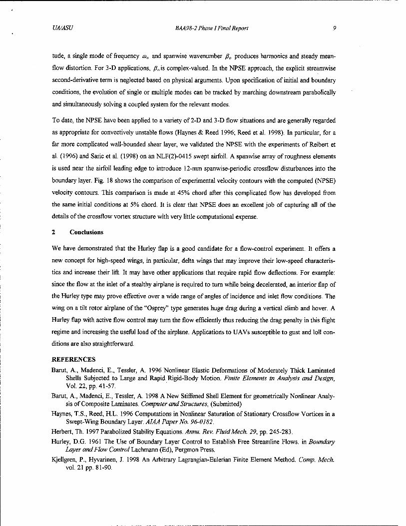
Combining steady blowing with periodic excitation increased the maximum lift at proportionally smaller in-
crements. For example, the addition of 0^ = 2% to the existing excitation of <cfl2> = 0.5% increased CLmax
from 2.7 to 3.05, while the addition of C^ = 5% raised CLmax to 3.25 (Fig. 7). At small angles of incidence,
the addition of steady blowing sufficed to control separation making periodic excitation superfluous. How-
ever at a greater than 15° any addition of oscillations was beneficial provided C^ was less than 10%.
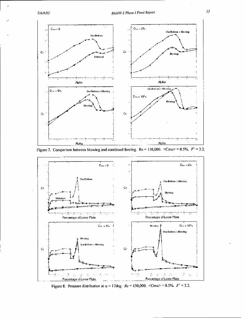
Oscillations emanating from the slot reduced the pressure upstream of the cylinder (on the upper surface of
the main element; see Fig. 3), changing the average Cp there from -1.7 to -4. It required ten times larger C^
to achieve a similar reduction in Cp (Fig. 8). One observes from the pressure distribution that purely periodic
oscillations are able to attach the flow to the upper surface of the flap.
UA/ASU BAA98-2 Phase 1 Final Report 4
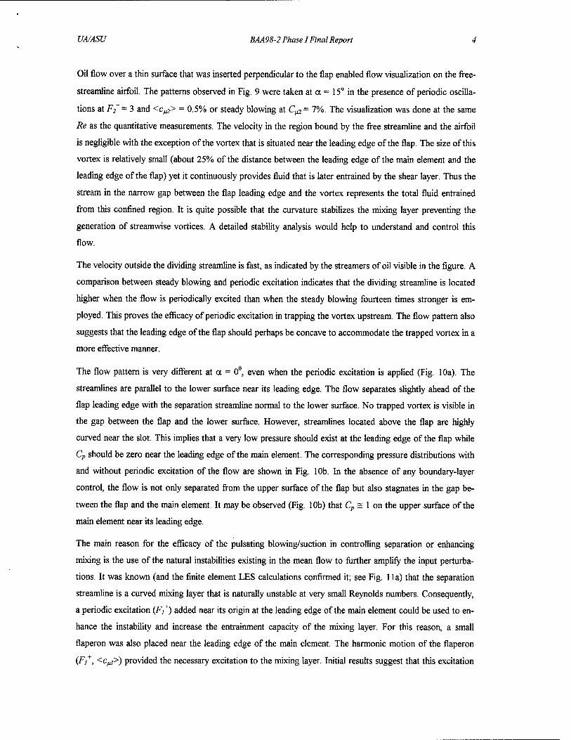
Oil flow over a thin surface that was inserted perpendicular to the flap enabled flow visualization on the free-
streamline airfoil. The patterns observed in Fig. 9 were taken at a = 15° in the presence of periodic oscilla-
tions at F2+ = 3 and <c^> = 0.5% or steady blowing at C^ = 7%. The visualization was done at the same
Re as the quantitative measurements. The velocity in the region bound by the free streamline and the airfoil
is negligible with the exception of the vortex that is situated near the leading edge of the flap. The size of this
vortex is relatively small (about 25% of the distance between the leading edge of the main element and the
leading edge of the flap) yet it continuously provides fluid that is later entrained by the shear layer. Thus the
stream in the narrow gap between the flap leading edge and the vortex represents the total fluid entrained
from this confined region. It is quite possible that the curvature stabilizes the mixing layer preventing the
generation of streamwise vortices. A detailed stability analysis would help to understand and control this
flow.
The velocity outside the dividing streamline is fast, as indicated by the streamers of oil visible in the figure. A
comparison between steady blowing and periodic excitation indicates that the dividing streamline is located
higher when the flow is periodically excited than when the steady blowing fourteen times stronger is em-
ployed. This proves the efficacy of periodic excitation in trapping the vortex upstream. The flow pattern also
suggests that the leading edge of the flap should perhaps be concave to accommodate the trapped vortex in a
more effective manner.
The flow pattern is very different at a = 0°, even when the periodic excitation is applied (Fig. 10a). The
streamlines are parallel to the lower surface near its leading edge. The flow separates slightly ahead of the
flap leading edge with the separation streamline normal to the lower surface. No trapped vortex is visible in
the gap between the flap and the lower surface. However, streamlines located above the flap are highly
curved near the slot. This implies that a very low pressure should exist at the leading edge of the flap while
Cp should be zero near the leading edge of the main element. The corresponding pressure distributions with
and without periodic excitation of the flow are shown in Fig. 10b. In the absence of any boundary-layer
control, the flow is not only separated from the upper surface of the flap but also stagnates in the gap be-
tween the flap and the main element. It may be observed (Fig. 10b) that Cp = 1 on the upper surface of the
main element near its leading edge.
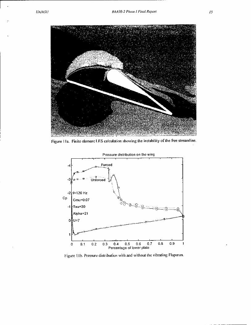
The main reason for the efficacy of the pulsating blowing/suction in controlling separation or enhancing
mixing is the use of the natural instabilities existing in the mean flow to further amplify the input perturba-
tions. It was known (and the finite element LES calculations confirmed it; see Fig. 11a) that the separation
streamline is a curved mixing layer that is naturally unstable at very small Reynolds numbers. Consequently,
a periodic excitation (F/) added near its origin at the leading edge of the main element could be used to en-
hance the instability and increase the entrainment capacity of the mixing layer. For this reason, a small
flaperon was also placed near the leading edge of the main element. The harmonic motion of the flaperon
(F]+, <c^>) provided the necessary excitation to the mixing layer. Initial results suggest that this excitation

UA/ASU BAA98-2 Phase 1Final Report 5
could further increase the lift generated by the free-streamline airfoil because it lowered the pressure within
the trapped vortex (Fig. lib). A proper parametric study of this effect will be conducted during the second
phase of this project.
Fluid-Structure Interaction
As part of the first phase of this project, a coupled fluid-structure interaction analysis algorithm was devel-
oped based on the Finite Element Method (FEM). As described in Fig. 12a-e, this algorithm solves the
equations of aerodynamics and structural dynamics in a sequentially coupled manner. The results from the
solution of Navier-Stokes equations provide the fluid forces as input for the subsequent structural dynamic
analysis. Because the fluid flow and thus the fluid forces are dependent on the geometry of the structure, the
computational mesh is updated for the subsequent aerodynamic analysis based on the deformed configura-
tion.
First, the fluid flow in the domain surrounding the structure is calculated by solving the Navier-Stokes equa-
tions. A view of a typical computational domain for the fluid flow analysis is shown in Fig. 12a. The flexible
structure, in this case a wing, is discretized using shell elements. A view of a typical computational discreti-
zation for a wing is shown in Fig. 12b. The pressure distribution obtained from the fluid flow analysis is
transferred to the wing as illustrated in Fig. 12c. These forces will cause the wing to deform as shown in Fig.
12d. Because the wing experiences deformation, its shape changes; thus, the fluid flow also changes and the
flowfield analysis must be redone. The deformed structural computational mesh for the wing becomes the
new boundary positions of the computational domain for the flowfield analysis shown in Fig. 12e. When as-
signing new boundary positions for the computational domain for the flowfield, the computational mesh
must be updated with a re-zoning algorithm. Since the flowfield is highly unsteady, the flow-induced dis-
placements are analyzed in the time domain. Therefore, the above-described steps, as summarized in Fig.
12f, must be performed at every time step of the calculation.
The structural-analysis part of the algorithm developed by Madenci and Barut (1996) and later applied to
moderately thick composite components by Barut et al. (1997) accounts for the coupling between the rigid-
body motion and elastic deformations. Unlike others, this algorithm is capable of capturing the motion-
induced membrane and stiffness variations of general shell structures because the nonlinear strain measure
and rotations are explicitly included in the formulation. The formulation of the mass matrix includes the cou-
pling between rigid-body motion, inertial forces and elastic deformation so that the inertial loads can be
determined as part of the solution. Changes in the inertial loads due to rapid maneuver or external aerody-
namic and actuator loads are captured in this formulation; they can be significant in the aero-elastic tailoring
of the aircraft or aerospace structure. In addition, this algorithm, described in detail by Madenci and Barut
(1996), accounts for large elastic displacements and rotations, material anisotropy, transverse shear defor-
mations, motion induced stiffening and softening.
UA/ASU BAA98-2 Phase I Final Report 6
As shown by Madenci and Barut (1996), utilizing concepts from finite-element analysis within the realm of
nonlinear theory of elasticity as well as rigid-body dynamics and applying the principle of virtual work in
conjunction with co-rotational form of the updated Lagrangian description of motion leads to the coupled
and highly nonlinear equations of motion for the finite element. The solution vector provides the position
and rigid-body rotation of the body-fixed frame and the incremental total nodal vector that represents the
flexible part of the motion. The components of the position and rigid-body rotation vectors are measured
with respect to the inertial frame, while the body-fixed frame is chosen to measure the components of the
total nodal vector. Therefore, the freedom in the choice of different frames of reference makes this formula-
tion different than other existing formulations in which they use a single frame of reference to measure the
overall motion. Relating these vectors is the fully coupled and symmetric mass matrix. In most of the for-
mulations, the terms originating from gyroscopic forces are lumped into the mass matrix in a skew-
symmetric form, which results in a non-symmetric mass matrix. However, in this approach, the symmetry of
the mass matrix is established by retaining the gyroscopic forces in the right-hand-side vector in addition to
the external forces. The vectors arising from the internal forces are also provided to complete the nonlinear
forcing terms (all dependent on the solution vector) in the equations of motion. The incremental part of the
internal force vector involves the tangential stiffness matrix, which is decomposed as linear and geometric
stiffness matrices.
There exists no analysis except for Madenci and Barut (1996) and Barut et al. (1997) regarding the dynamic
response of composite shells undergoing large overall motion accompanied by large elastic displacements
and rotations. Their analysis is capable of capturing the motion-induced membrane and stiffness variations
because the nonlinear strain measure and rotations are explicitly included in the formulation and the inertial
forces are determined as part of the solution. In other words, the rigid-body motion is not known a priori.
Also, their formulation permits the inclusion of time-dependent external forces such as the aerodynamic
loads. It is to be noted that none of the available finite-element analyses, including the commercial programs,
have the capability to solve this problem within the realm of multi-body dynamics formalism.
Previous studies relevant to the structural dynamics of a composite component are not capable of including
the effect of externally applied dynamic loads such as the aerodynamic forces, time-dependent angular ve-
locity and the influence of the coupling between the rigid-body motion, elastic deformations and the inertial
forces. An extensive review of these multi-body dynamics formulations coupled with elastic deformations
can be found in a study by Madenci and Barut (1996).
The aerodynamic-analysis part of the algorithm developed by Kjellgren and Hyvarinen (1998) and Kjellgren
(1997 and 1998) provides the solution of the unsteady Navier-Stokes equations. The formulation is based on
an arbitrary Lagrangian-Eulerian description of motion suitable for moving or deformable bodies. It utilizes a
semi-implicit fractional-step finite-element method for general two and three dimensions and a Large Eddy

UA/ASU BAA98-2 Phase I Final Report 7
Simulation (LES) for three-dimensional turbulent flow. The updating of the mesh required between the
structural dynamics and aerodynamic analyses is based on a novel re-zoning algorithm.
This FEM-based fluid-structure interaction analysis algorithm applies to both the fluid domain and the
structure with complex two- or three-dimensional geometry under general boundary conditions. Also, this
algorithm is fully interfaced with the pre-and post processor of ANSYS, a commercially available finite-
element program. In order to demonstrate the capability of this algorithm, a number of calculations in both
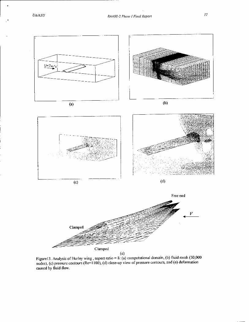
two and three dimensions were performed. The first case is a computational analysis of the structural re-
sponse due to fluid forces of a three-dimensional Hurley wing with aspect ratio of eight. This calculation was
performed at Re = 1100. No wing-tip effects were included. The computational domain is shown in Fig. 13a
and the computational mesh in Fig. 13b. The pressure caused on the wing by the fluid flow is shown in Figs.
13c and 13d, and the corresponding deformation is shown in Fig. 13e.
The second case is a computational analysis of the flow field around a stationary Hurley wing. This analysis
was performed at the actual Reynolds number, Re = 120,000, which is high enough for turbulence to play a
significant role and thus, a large eddy simulation (LES) turbulence model is included. The analysis is done
for a slice of the wing, rendering the calculations three dimensional. A schematic view of the computational
domain is shown in Fig. 14a. The mesh contains about 200,000 nodes; a close-up view of a slice of the mesh
is shown in Fig. 14b. Velocity and pressure contours are shown in Figs. 14c and 14d. Note that the compu-
tational predictions of CD and Q. are in very close agreement with the experimental measurements and
observations.
The third case is the same as the second case except for the presence of the blowing slot for boundary-layer
control. Velocity and pressure contours are shown in Figs. 15a and 15b. As observed in these figures, it is
clear that the blowing slot promotes reattachment, reduces the wake, and thus improves the performance.
From computer animations, it is also clear that the blowing slot keeps the vortex confined between the upper
and the lower surfaces. The vortex is stronger and steadier, which also improves the lift characteristics.
Overall, the results indicate that the lift and drag coefficients can be improved significantly by boundary-layer
control. Again, these computational predictions of Q compare remarkably well with the experimental meas-
urements and observations.
In the fourth case, in order to demonstrate the capability of the fluid-structure interaction algorithm, the
Hurley airfoil with a flexible flap and rather stiff lower surface is calculated at Re = 2100. The upper flap is
modeled as consisting of two rather flexible quasi-isotropic laminates. A schematic view of the structure also
showing the direction of the in-coming flow is shown in Fig. 16a. In order to capture the response over a
time interval of the fluid-structure interaction, the time-history of the vertical displacement of the tip of the
upper flap is shown in Fig. 16b. Based on this figure, the system seems to be aero-elastically stable. The ve-

UA/ASU BAA98-2 Phase I Final Report 8
locity contours when the upper flap is at its bottom position are shown in Fig. 16c and the velocity contours
when it is at the top position are shown in Fig. 16d.
In the fifth case, in addition to elastic deformation, the airfoil is allowed to have rigid-body motion through
its attachment to linear and torsional springs at its corner as shown in Fig. 17a. This is a generalization of the
"typical section airfoil" (a rigid airfoil attached to springs) often used in aero-elastic analyses and is a very
useful model for determining the basic aero-elastic properties of the wing. The time-history of the vertical
displacement of the tip of the upper flap is shown in Fig. 17b.
Nonlinear parabolized stability equations
The visualizations shown in the previous sections clearly indicate a natural instability of the shear layer ema-
nating off the main element. The entrainment in the free mixing layer is enhanced by these low-frequency
oscillations, resulting in the early roll-up of vortices and more efficient attachment to the flap. To capitalize
on this effect, oscillations with frequencies corresponding to those of the disturbances most-amplified natu-
rally are introduced at the leading edge of the lower surface (main element) to further enhance the
instabilities. A stability analysis to determine the physics of the free-shear-layer behavior and the disturbances
most amplified naturally is done around the structural vibration computations described in previous sections;
this determines the most efficient input for control (F/). The shear layer grows spatially and is curved; these
physical effects must be included in the stability analysis.
Stability theory and nonlinear parabolized stability equation (NPSE; Herbert 1997) simulations predict the
most unstable or most effective frequencies for control by periodic perturbations. Recent experiments in ar-
tificially excited shear layers suggest that data are well correlated with nonlinear inviscid instability theory.
On the basis of this and as a first step, spatial instability theory has been extended to a slowly divergent pre-
scribed mean flow; in particular, a tanh(y) profile for two parallel streams of different speed that are allowed
to mix. Preliminary results show that two-dimensional oscillations tend to increase in amplitude until a neu-
trally stable Strouhal number is attained. The results are in excellent agreement with the experiments of
Wygnanski and Petersen (1987). Current calculations include the effects of the curvature characteristic of
the free streamline leaving the leading edge of the lower surface and reattaching at the upper surface. To this
end, the radius of curvature is varied parametrically to determine its effect on stability.
The next step is the application of the NPSE to the structural vibration computations described in previous
sections. In recent years the NPSE have become a popular approach to analyzing streamwise growth of lin-
ear and nonlinear disturbances in slowly varying shear layers, jets, and boundary layers. The NPSE include
nonparallel and nonlinear effects ignored by linear stability theory. Moreover, the NPSE have significantly
less resource overhead associated with them compared with direct numerical simulations (Herbert 1997).
Using a multiple-scales approach, each disturbance quantity is decomposed spectrally into a rapidly varying
wave function and a slowly varying shape function in the spanwise and temporal directions. At finite ampli-
UA/ASU BAA98-2 Phase 1 Final Report 9
tude, a single mode of frequency eo0 and spanwise wavenumber ß0 produces harmonics and steady mean-
flow distortion. For 3-D applications, ß0is complex-valued. In the NPSE approach, the explicit streamwise
second-derivative term is neglected based on physical arguments. Upon specification of initial and boundary
conditions, the evolution of single or multiple modes can be tracked by marching downstream parabolically
and simultaneously solving a coupled system for the relevant modes.
To date, the NPSE have been applied to a variety of 2-D and 3-D flow situations and are generally regarded
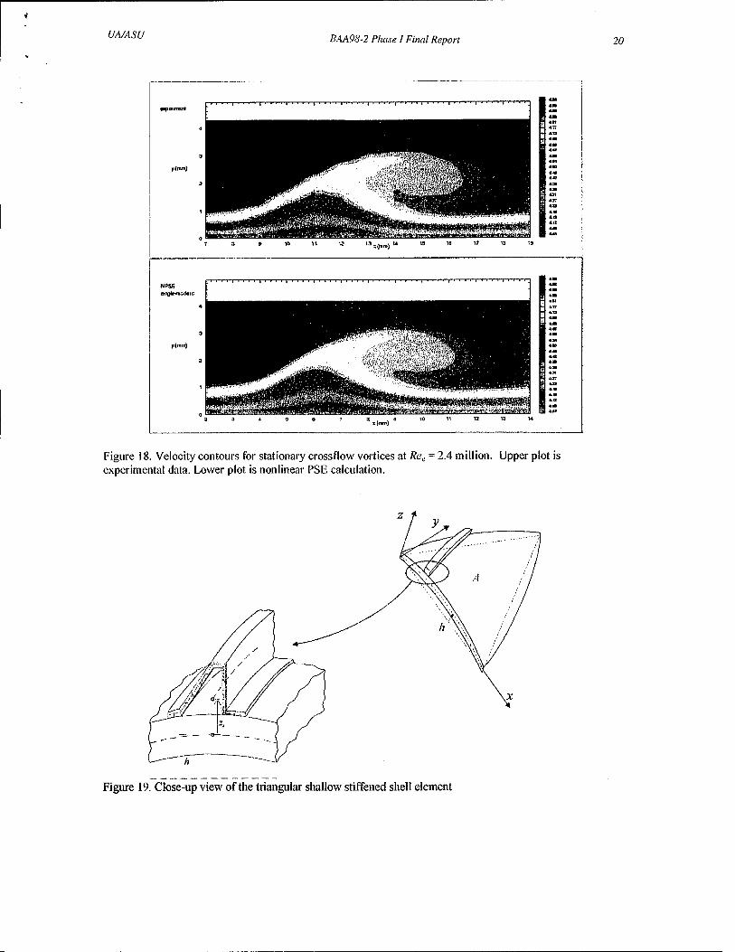
as appropriate for convectively unstable flows (Haynes & Reed 1996; Reed et al. 1998). In particular, for a
far more complicated wall-bounded shear layer, we validated the NPSE with the experiments of Reibert et
al. (1996) and Saric et al. (1998) on an NLF(2)-0415 swept airfoil. A spanwise array of roughness elements
is used near the airfoil leading edge to introduce 12-mm spanwise-periodic crossflow disturbances into the
boundary layer. Fig. 18 shows the comparison of experimental velocity contours with the computed (NPSE)
velocity contours. This comparison is made at 45% chord after this complicated flow has developed from
the same initial conditions at 5% chord. It is clear that NPSE does an excellent job of capturing all of the
details of the crossflow vortex structure with very little computational expense.
2 Conclusions
We have demonstrated that the Hurley flap is a good candidate for a flow-control experiment. It offers a
new concept for high-speed wings, in particular, delta wings that may improve their low-speed characteris-
tics and increase their lift. It may have other applications that require rapid flow deflections. For example:
since the flow at the inlet of a stealthy airplane is required to turn while being decelerated, an interior flap of
the Hurley type may prove effective over a wide range of angles of incidence and inlet flow conditions. The
wing on a tilt rotor airplane of the "Osprey" type generates huge drag during a vertical climb and hover. A
Hurley flap with active flow control may turn the flow efficiently thus reducing the drag penalty in this flight
regime and increasing the useful load of the airplane. Applications to UAVs susceptible to gust and loll con-
ditions are also straightforward.
REFERENCES
Barut, A., Madenci, E., Tessler, A. 1996 Nonlinear Elastic Deformations of Moderately Thick Laminated Shells Subjected to Large and Rapid Rigid-Body Motion. Finite Elements in Analysis and Design, Vol. 22, pp. 41-57.
Barut, A., Madenci, E., Tessler, A. 1998 A New Stiffened Shell Element for geometrically Nonlinear Analy- sis of Composite Laminates. Computer and Structures, (Submitted)
Haynes, T.S., Reed, H.L. 1996 Computations in Nonlinear Saturation of Stationary Crossflow Vortices in a Swept-Wing Boundary Layer. AIAA Paper No. 96-0182.
Herbert, Th. 1997 Parabolized Stability Equations. Annu. Rev. Fluid Meek 29, pp. 245-283.
Hurley, D.G. 1961 The Use of Boundary Layer Control to Establish Free Streamline Flows, in Boundary Layer and Flow Control Lachmann (Ed), Pergmon Press.
Kjellgren, P., Hyvarinen, J. 1998 An Arbitrary Lagrangian-Eulerian Finite Element Method. Comp. Mech. vol. 21 pp. 81-90.

UA/ASU BAA98-2 Phase I Final Report 10
Kjellgren, P. 1997 A Semi-Implicit Fractional Step Finite Element Method for Viscous Incompressible Flows. Comp. Meek vol. 20, pp. 541-50.
Kjellgren, P. 1998 A Finite Element Method for Large Eddy Simulation of Turbulent Flows. Technical Re- port 98-16, Department of Aeronautics, Royal Institute of Technology, Stockholm, Sweden.
Madenci, E., Barut, A. 1996 Dynamic Response of Thin Composite Shells Experiencing Nonlinear Elastic Deformations and Large Overall Motions. International J. Num. Methods in Eng. vol. 39, pp. 2695- 723.
Naveh, A, Seifert, A., Tumin,A, Wygnanski, I. 1998 The Effect of Sweep on the Parameters Governing the Control of Separation by Periodic Motion. To appear J. of Aircraft.
Nishri, B., Wygnanski, I. 1998 The effects of periodic excitation on turbulent flow separation from a flap. In press AIAA J.
Reed, H.L., Haynes, T.S., Saric, W.S. 1998 CFD-Validation Issues in Transition Modelling, AIAA J. 36, 5, pp. 742-51
Reibert, M.S., Saric, W.S., Carrillo, R.B., Chapman, K.L. 1996 Experiments in Nonlinear Saturation of Sta- tionary Crossflow Vortices. AIAA Paper No. 96-0184.
Saric, W.S. 1992 The ASU Transition Research Facility. AIAA Paper No. 92-3910.
Saric, W.S., Carrillo, R, Reibert, M. 1998 Leading-edge Roughness as a Transition Control Mechanism. AIAA Paper No. 98-0781.
Seifert, A., Bachar, T., Koss, D., Shepshelovich, M., Wygnanski, I. 1993 Oscillatory Blowing, a Tool to Delay Boundary Layer Separation. AIAA J. 31, No. 11,. pp. 2052-60.
Siefert, A., Pack, L.G. 1998 Oscillatory Control of Separation a High Reynolds Numbers. AIAA Paper No. 98-0214.
Wygnanski, I, Petersen, RA. 1987 Coherent Motion in Excited Free Shear Flows, AIAA J. 25, 2, pp. 201- 13.
Yang, X., Grosjean, C, Tai, Y.C., Ho, CM. 1997 A MEMS Thermopneumatic Silicone Membrane Valve. Proc. 1997 IEEE MEMS Workshop pp. 114-8.

UA/ASU BAA98-2 Phase I Final Report
Sweep=60°, a=30°, Re=4*105
Basic
Reattachment Line
b" f*Xu
Uo
UN\
,~-i
Reattachment Line
s..
Figure 1. Flow control over delta wing.
VORTICAL FLOW ABOVE A DELTA WING
Prlmory Vortex
Secondary Vortex -
Figure 2. Vortical flow and Hurley flap as delta wing.
11
Free Streamline
KM.
V/,2'^2 9\^/3
a • \
Figure 3. Significant parameters. Geometrical parameters are c, x, K, a, and slot location. Flow
parameters are F,+ , (c^, C^2, F2V, {c^2, and Re.

UA/ASU BAA9S-2 Phase I Final Report 12
i;
~i r
Alpha
Figure 4. The effect of steady blowing. Re= 150,000.
Alpha
Figure 5. Influence of steady blowing and combined forcing. Re= 150,000. <Cmu> = 0.5%. F* = 3.2.
25
1 ' |""'" | -.-!■■
s A
■ /
,.'
0 0 untoicod
---■■'" Jl Oscillations
1 1 1
* ri Oscillations F*=32
5 '0 15 23 25 3«
Alpha
0 O Unlorcod
Oscillations F*=l 1
t * Oscillations F'=3 2
0.1 02 03 04 05 0» CD
Figure 6. The Effect of Frequency on Lift and Drag
UA/ASU BAA98-2 Phase I Final Report 13
Ci
C.MÜ = 0
./ .^' ^ \
^ s .<<" y
V».
sf Un lot cod
-i
—!.,_ 1.,.
.,.. 1 1
Ci:.. = 2% OsciUa lions * Bb'.viug
i
1
Ci
\
6 Dto'Atng
j
i "i
!
i
>-~— ._, .,„,..„.. _, 4,UlJ..,r,-r.-^»- .. i • i
■]
Alpha Alpha
Ci-u ~ S'/o Oscillation« + Bfo.vlrv:)
^r\ Ci
Dlowiny
Ms«^
Alpha Alpha
Figure 7. Comparison between blowing and combined forcing. Re =150,000. <Cmu>-0.5%. Ff = 3.2.
&,«. * 0
/
Cim*2%
Oecillotions + Blov.iucj
O
rv ( Unloic'ed f >f-0 * * it 4 &-* «wfr-SKw^s
O
/■^ ^it Dlov.inci
Percentage of Lower Plate
Ci-
Blciufcnj f Ctn.»10%
Oscilliltbns + Blearing
"•Saw
Percentage o( Lower Plate Percentage o( Lower Plate
Figure 8. Pressure distribution at a = I7deg. Re= 150,000. <Cmu> = 0.5%. F"" = 3.2.

UA/ASU BAA98-2 Phase I Final Report 14
»va-awy?
Figure 9a. Flow visualization with oscillating blowing. <Cmu> = 0.5%. ot=15deg.
Figure 9b. Flow visualization of steady blowing. Cmu = 7%, a = 15deg.
Figure 10a. Flow visualization of oscillating blowing. <Cmu> = 0.5%. a = Odeg.
a-,-, .o AlpH-i - 0 A
l ÜtdllltlulU
Ä—■tr e-
^Y**&=£$c^ \,
rt -1 ■) 7 ft * rt 4. 0 -I 1(1 "7 ft ^ ft •> 1
P*r-:<?nfcb;i4 of U-vV-fr Ptot*
Figure I Ob. Pressure distribution at a = Odeg.
UA/ASU BAA98-2 Phase I Final Report 15
Figure I la. Finite element LES calculation showing the instability of the free streamline.
Pressure distribution on the wing
0 0.1 0.2 0.3 0.4 0.5 0.6 0.7 0.8 0.9 1 Percentage of lower plate
Figure I lb. Pressure distribution with and without the vibrating Flaperon.

UA/ASU BAA98-2 Phase I Final Report 16
\ \
\1 \ (a)
o\ (d)
\ X
\l \
Solution of Navier-Stokes equations
Calculate force distribution on structure
Calculate structural deformations
Update computational mesh
(e) (f) Figure 12: (a) Typical computational domain for fluid flow; (b) typical mesh for structural analysis; (c) transfer of pressure forces from fluid analysis to structural mesh; (d) deformation due to pressure forces; (e) updated computational domain for fluid flow; (f) the sequential fluid-structure interaction algorithm
UA/ASU BAA98-2 Phase I Final Report 17
(a)
(c)
.«#&j-f2>
(d)
S^fi,
Free end
Clamped
Clamped (e)
Figure 13. Analysis of Hurley wing , aspect ratio = 8: (a) computational domain, (b) fluid mesh (50,000 nodes), (c) pressure contours (Re=l 100), (d) close-up view of pressure contours, and (e) deformation caused by fluid flow.

UA/ASU BAA9S-2 Phase I Final Report 18
\
4cm
(a) (b)
WKSSaMm
(c)
■...'.■■■'■," - ■""• :•"'':■.' . • '»!v' §1§ -' /
(d) Figure 14. LES calculation at Re = 120,000: (a) computational domain (not to scale); (b) close-up view of a slice of the LES fluid mesh (200,000 nodes); (c) velocity contours from unsteady, 3-D LES, C,. = 1.2, CD = 0.28 (Exp: CL = 1.2, CD = 0.27); and (d) presssure contours.
iife
(a) (b) Figure 15. LES calculation at Re = 120,000, blowing slot with C(l = 0.09: (a) velocity contours from unsteady 3-D LES, C,, = 2.5 (Exp: 2.5); and (b) pressure contours.

UA/ASU BAA98-2 Phase I Final Report 19
Stiff lower section
(a)
Timo-hictoiy of depfaccroont at llap tip n f f ! r
' i i '1 Ml
Hfi
(b)
O.B 0.8 1 Time (a)
(c) (d) Figure 16. Fluid-structure interaction of Hurley wing with flexible flap: (a) idealized model of Hurley airfoil, (b) time-history of vertical displacement of upper flap tip, (c) velocity contours at bottom position, and (d) velocity contours at top position.
lino tir.ory ol orjnticomorI at Rap :lo
Flexible flap
02 OJ 0,0 0.9
(a) (b) Figure 17. Fluid-structure interaction of Hurley wing attached to springs: (a) idealized model of the Hurley airfoil and (b) time-history of vertical displacement of upper flap tip.
UA/ASU BAA98-2 Phase I Final Report 20
NPS6 ongte-fxxtaic
»(">"*
Figure 18. Velocity contours for stationary crossflow vortices at Rea = 2.4 million. Upper plot is experimental data. Lower plot is nonlinear PSE calculation.
Figure 19. Close-up view of the triangular shallow stiffened shell element