Embed Size (px)
Citation preview
Proceedings of Acoustics 2012 - Fremantle 21-23 November 2012, Fremantle, Australia
Australian Acoustical Society 1
Correlation of pump efficiency and shaft torsional vibra-tion using torsional laser vibrometry
Andrew Louis Guzzomi and Jie Pan (1) School of Mechanical and Chemical Engineering, University of Western Australia, Perth, Western Australia
ABSTRACT The extensive use of centrifugal pumps in mining, potable water supply and sanitary installations potentially present an opportunity for energy savings through pump efficiency monitoring. Pumping units in these applications typically incorporate a flexible coupling between the motor and the pump. This coupling permits some shaft misalignment and provides vibration isolation. It is however unknown how significant torsional vibration is between the motor output and the impeller input. Changes in shaft torsional vibration could be a result of variations in the impeller’s torque due to hydrodynamic loading, which may indicate the pump’s efficiency. This paper presents a preliminary experimental study into the shaft torsional vibration on each side of the coupling of a centrifugal pump. This is achieved using a non-contact technique involving two torsional laser vibrometers. In addition to providing a correlation to pump effi-ciency, the method also permits the investigation of impeller angular velocity frequency content and these aspects are discussed in the context of current state-of-the-art in monitoring of pump’s performance.
INTRODUCTION
Historical background
The origins of the centrifugal pump date back centuries and it its very conception was born out of a necessity to increase efficiency in fluid transport systems. It has been stated (Reti, 1963) that Francesco di Giorgio’s (1439 – 1502) 1475 Trat-tato presents a device which must be characterised as the prototype to the modern centrifugal pump. According to No-lan (1998), Denis Papin (1647-c.1712), a French physicist and inventor, produced a centrifugal pump with straight vanes and in 1851, John G. Appold (1800 – 1865), who was a British engineer and inventor, introduced a curved-vane cen-trifugal pump which was much more efficient.
An early account of a centrifugal pump’s workings is given by Franz Reuleaux (1829 – 1905) in his most famous work ‘The Constructor’. In the fourth enlarged German edition’s (1893) section on ‘Running mechanism in which the pressure organ is driven by transfer of living force’ he describes the centrifugal pump as a device for moving liquids, consisting of curved blades which, when seeking improved efficency, are integral with the wheel [to form the impeller]. His repre-sentation is depicted in Figure 1.
Figure 1. Centrifugal pump as depicted by Reuleaux (1893).
The simple workings of centrifugal pumps have made them the common choice for large scale fluid transfer. From the outset they found application in dredging operations lifting
wet sand, gravel and mud (Reuleaux, 1893). A remarkable centrifugal pump installation for water transport of 1887 was that consisting of five such pumps built by Farcot, Paris, for supplying Katatbeh Canal in Egypt. Each 12’6” diameter wheel delivered 17660000 cubic feet of water in 23 hours with lifts between 1 and 12’ (Reuleaux, 1893).
State-of-the-art
Today centrifugal pumps have become widely adopted in fluid handling within mining, agriculture, potable water sup-ply and sanitary installations. Accordingly a great deal of research has been conducted both theoretically and experi-mentally towards understanding their performance under different operating conditions. It is well established that the centrifugal pump works by imparting momentum onto the fluid within the volute. The interaction of the fluid on the impeller gives rise to time and space variant forces. These arise from pressure fluctuations due to the changing geometry and that the pumped fluid behaves essentially incompressi-bly.
Investigations into the pressure variations within the volute continue to be the topic of numerous experimental and com-putational studies (González et al., 2002). The coupling of this pressure to structural components such as the volute and piping have also been investigated. Although vibration meas-urement on pumps from a condition monitoring perspective is today common, it is typically used to spot such phenomena as cavitation, the blade passing frequency (BPF) and bearing faults. Early work into impeller forces in centrifugal pumps was conducted by various researchers including Binder and Knapp (1936), Acosta and Bowerman (1957), Stepanoff (1957) and Agostinelli et al. (1960). This is not an exhaustive list.
There is a growing trend in many industries to ensure effi-cient use of energy. The extensive use of centrifugal pumps throughout Australia potentially presents an opportunity for energy savings through pump efficiency monitoring. At the University of Western Australia there has been a push to
Paper Peer Reviewed
21-23 November 2012, Fremantle, Australia Proceedings of Acoustics 2012 - Fremantle
2 Australian Acoustical Society
extend the state-of-the-art to use vibration measurement to infer pump efficiency (Hodkiewics, 2004; Wang, 2012).
Contextual scope
Since pump vibration results from the excitation of unsteady flow, which in turn is dependent on the fluid interaction with the impeller and the volute, an efficient passage of pump fluid flow would likely result in less energy being dissipated through collisions. The vibration generated from this fluid excitation can be inferred from pressure fluctuations simulat-ed through CFD and can be readily measured on the volute with accelerometers (Wang, 2012). Although in theory an efficiency monitoring system seems plausible from a conser-vation of energy argument, it is also true that the knowledge about unsteady pressure fluctuations and blade loading is still not satisfactory (Pavesi, 2006). As noted by Pavesi (2006), the pump volute defines the surroundings in which the impel-ler operates. It thus has a profound effect on the impeller performance and can cause the impeller to work inefficiently depending on the flowate.
Before a pump is commissioned the pump efficiency typical-ly has to be confirmed by the supplier prior to hand-over to the client. To achieve this, the accepted industry standard is to measure the motor current with a loss factor and rotational speed for the input power, and pressure and flow rate at the discharge for the work done by the pump. This method as-sumes that the subsequent inferred motor torque is then sup-plied to the impeller without loss. This is however only true if the shaft output of the motor is indeed the input torque of the impeller. However, most centrifugal pump designs incorpo-rate a flexible coupling between the motor and the pump. This coupling permits some shaft misalignment and provides vibration isolation. It is typically made of rubber material. It is unknown how significant torsional vibration is between the motor output and the impeller input. The occurrence of tor-sional vibration could ultimately result in variation of the impeller’s torque.
In this context, this paper presents the first preliminary exper-imental study into the effects of shaft torsional vibration on each side of the coupling of a centrifugal pump. This is achieved using a non-contact technique involving two laser torsional vibrometers for input into the impeller. In addition to providing a correlation to pump efficiency, the method also permits the investigation of impeller angular velocity frequency content.
EXPERIMENTAL SET-UP
This section outlines the experimental methodology used in this project.
Pump test rig
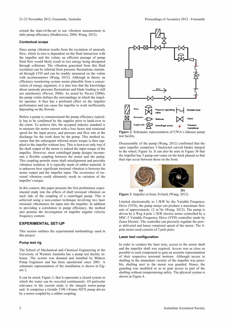
The School of Mechanical and Chemical Engineering at the University of Western Australia has a pump test facility in-house. The system was donated and installed by Blakers Pump Engineers and has been operational since 2001. A schematic representation of the installation is shown in Fig-ure 2.
It can be noted, Figure 2, that it represents a closed system in which the water can be recycled continuously. Of particular relevance to the current study is the integral motor-pump unit. It comprises a Goulds 3196 i-Frame MTX pump driven by a motor coupled by a rubber coupling.
Figure 2. Schematic representation of UWA’s inhouse pump test facility.
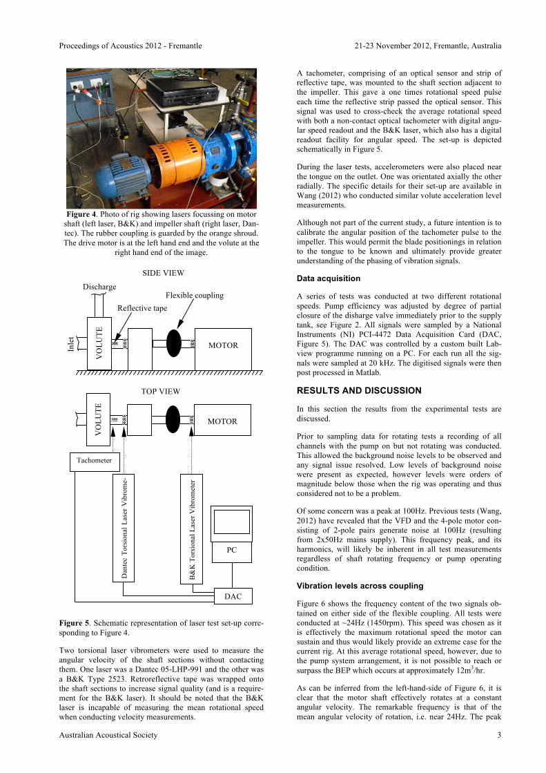
Dissassembly of the pump (Wang, 2012) confirmed that the open impeller comprises 5 backward curved blades integral to the wheel, Figure 3a. It can also be seen in Figure 3b that the impeller has 5 pump-out-vanes on the back phased so that their tips occur between those on the front.
(a) (b)
Figure 3. Impeller a) front, b) back (Wang, 2012)
Limited electronically to 1.5kW by the Variable Frequency Drive (VFD), the pump motor can produce a maximum flow rate of approximately 12 m3/hr (Wang, 2012). The pump is driven by a Weg 4-pole 1.5kW electric motor controlled by a MSC-3 Variable Frequency Drive (VFD) controller made by Zener Electric. The controller can precisely regulate the pow-er delivered and hence rotational speed of the motor. The 4-pole motor used consists of 2 pole pairs.
Laser test configuration
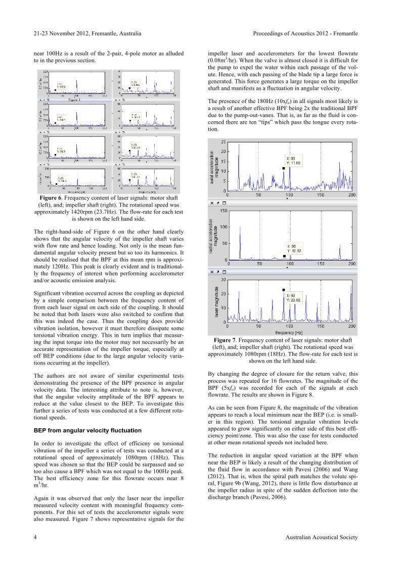
In order to conduct the laser tests, access to the motor shaft and the impeller shaft was required. Access was as close as possible to each component to gain an accurate representation of their respective torsional motions. Although access to shafting in the immediate vicinity of the impeller was possi-ble, shafting next to the motor was guarded. Hence, the guarding was modified so as to gain access to part of the shafting without compromising safety. The physical system is shown in Figure 4.
Proceedings of Acoustics 2012 - Fremantle 21-23 November 2012, Fremantle, Australia
Australian Acoustical Society 3
Figure 4. Photo of rig showing lasers focussing on motor
shaft (left laser, B&K) and impeller shaft (right laser, Dan-tec). The rubber coupling is guarded by the orange shroud. The drive motor is at the left hand end and the volute at the
right hand end of the image.
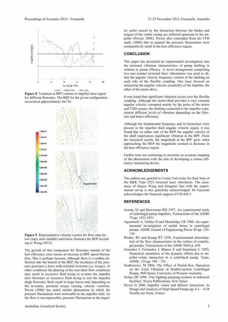
Figure 5. Schematic representation of laser test set-up corre-sponding to Figure 4.
Two torsional laser vibrometers were used to measure the angular velocity of the shaft sections without contacting them. One laser was a Dantec 05-LHP-991 and the other was a B&K Type 2523. Retroreflective tape was wrapped onto the shaft sections to increase signal quality (and is a require-ment for the B&K laser). It should be noted that the B&K laser is incapable of measuring the mean rotational speed when conducting velocity measurements.
A tachometer, comprising of an optical sensor and strip of reflective tape, was mounted to the shaft section adjacent to the impeller. This gave a one times rotational speed pulse each time the reflective strip passed the optical sensor. This signal was used to cross-check the average rotational speed with both a non-contact optical tachometer with digital angu-lar speed readout and the B&K laser, which also has a digital readout facility for angular speed. The set-up is depicted schematically in Figure 5.
During the laser tests, accelerometers were also placed near the tongue on the outlet. One was orientated axially the other radially. The specific details for their set-up are available in Wang (2012) who conducted similar volute acceleration level measurements.
Although not part of the current study, a future intention is to calibrate the angular position of the tachometer pulse to the impeller. This would permit the blade positionings in relation to the tongue to be known and ultimately provide greater understanding of the phasing of vibration signals.
Data acquisition
A series of tests was conducted at two different rotational speeds. Pump efficiency was adjusted by degree of partial closure of the disharge valve immediately prior to the supply tank, see Figure 2. All signals were sampled by a National Instruments (NI) PCI-4472 Data Acquisition Card (DAC, Figure 5). The DAC was controlled by a custom built Lab-view programme running on a PC. For each run all the sig-nals were sampled at 20 kHz. The digitised signals were then post processed in Matlab.
RESULTS AND DISCUSSION
In this section the results from the experimental tests are discussed.
Prior to sampling data for rotating tests a recording of all channels with the pump on but not rotating was conducted. This allowed the background noise levels to be observed and any signal issue resolved. Low levels of background noise were present as expected, however levels were orders of magnitude below those when the rig was operating and thus considered not to be a problem.
Of some concern was a peak at 100Hz. Previous tests (Wang, 2012) have revealed that the VFD and the 4-pole motor con-sisting of 2-pole pairs generate noise at 100Hz (resulting from 2x50Hz mains supply). This frequency peak, and its harmonics, will likely be inherent in all test measurements regardless of shaft rotating frequency or pump operating condition.
Vibration levels across coupling
Figure 6 shows the frequency content of the two signals ob-tained on either side of the flexible coupling. All tests were conducted at ~24Hz (1450rpm). This speed was chosen as it is effectively the maximum rotational speed the motor can sustain and thus would likely provide an extreme case for the current rig. At this average rotational speed, however, due to the pump system arrangement, it is not possible to reach or surpass the BEP which occurs at approximately 12m3/hr.
As can be inferred from the left-hand-side of Figure 6, it is clear that the motor shaft effectively rotates at a constant angular velocity. The remarkable frequency is that of the mean angular velocity of rotation, i.e. near 24Hz. The peak
Discharge
Inle
t
MOTOR
VO
LUTE
MOTOR
VO
LUTE
Flexible coupling
Dan
tec
Tors
iona
l Las
er V
ibro
me-
ter
B&
K T
orsi
onal
Las
er V
ibro
met
er
Tachometer
DAC
PC
Reflective tape
TOP VIEW
SIDE VIEW
21-23 November 2012, Fremantle, Australia Proceedings of Acoustics 2012 - Fremantle
4 Australian Acoustical Society
near 100Hz is a result of the 2-pair, 4-pole motor as alluded to in the previous section.
Figure 6. Frequency content of laser signals: motor shaft (left), and; impeller shaft (right). The rotational speed was
approximately 1420rpm (23.7Hz). The flow-rate for each test is shown on the left hand side.
The right-hand-side of Figure 6 on the other hand clearly shows that the angular velocity of the impeller shaft varies with flow rate and hence loading. Not only is the mean fun-damental angular velocity present but so too its harmonics. It should be realised that the BPF at this mean rpm is approxi-mately 120Hz. This peak is clearly evident and is traditional-ly the frequency of interest when performing accelerometer and/or acoustic emission analysis.
Significant vibration occurred across the coupling as depicted by a simple comparison between the frequency content of from each laser signal on each side of the coupling. It should be noted that both lasers were also switched to confirm that this was indeed the case. Thus the coupling does provide vibration isolation, however it must therefore dissipate some torsional vibration energy. This in turn implies that measur-ing the input torque into the motor may not necessarily be an accurate representation of the impeller torque, especially at off BEP conditions (due to the large angular velocity varia-tions occurring at the impeller).
The authors are not aware of similar experimental tests demonstrating the presence of the BPF presence in angular velocity data. The interesting attribute to note is, however, that the angular velocity amplitude of the BPF appears to reduce at the value closest to the BEP. To investigate this further a series of tests was conducted at a few different rota-tional speeds.
BEP from angular velocity fluctuation
In order to investigate the effect of efficieny on torsional vibration of the impeller a series of tests was conducted at a rotational speed of approximately 1080rpm (18Hz). This speed was chosen so that the BEP could be surpassed and so too also cause a BPF which was not equal to the 100Hz peak. The best efficiency zone for this flowrate occurs near 8 m3/hr.
Again it was observed that only the laser near the impeller measured velocity content with meaningful frequency com-ponents. For this set of tests the accelerometer signals were also measured. Figure 7 shows representative signals for the
impeller laser and accelerometers for the lowest flowrate (0.08m3/hr). When the valve is almost closed it is difficult for the pump to expel the water within each passage of the vol-ute. Hence, with each passing of the blade tip a large force is generated. This force generates a large torque on the impeller shaft and manifests as a fluctuation in angular velocity.
The presence of the 180Hz (10xfo) in all signals most likely is a result of another effective BPF being 2x the traditional BPF due to the pump-out-vanes. That is, as far as the fluid is con-cerned there are ten “tips” which pass the tongue every rota-tion.
Figure 7. Frequency content of laser signals: motor shaft (left), and; impeller shaft (right). The rotational speed was
approximately 1080rpm (18Hz). The flow-rate for each test is shown on the left hand side.
By changing the degree of closure for the return valve, this process was repeated for 16 flowrates. The magnitude of the BPF (5xfo) was recorded for each of the signals at each flowrate. The results are shown in Figure 8.
As can be seen from Figure 8, the magnitude of the vibration appears to reach a local minimum near the BEP (i.e. is small-er in this region). The torsional angualar vibration levels appeared to grow significantly on either side of this best effi-ciency point/zone. This was also the case for tests conducted at other mean rotational speeds not included here.
The reduction in angular speed variation at the BPF when near the BEP is likely a result of the changing distribution of the fluid flow in accordance with Pavesi (2006) and Wang (2012). That is, when the spiral path matches the volute spi-ral, Figure 9b (Wang, 2012), there is little flow disturbance at the impeller radius in spite of the sudden deflection into the discharge branch (Pavesi, 2006).
Proceedings of Acoustics 2012 - Fremantle 21-23 November 2012, Fremantle, Australia
Australian Acoustical Society 5
Figure 8. Variation in BPF content of impeller laser signal for different flowrates. The BEP for the given configuration occurred at approximately 8m3/hr.
Figure 9. Representative velocity vectors for flow rates be-low (top), near (middle) and below (bottom) the BEP accord-ing to Wang (2012).
The growth of this component for flowrates outside of the best efficiency zone causes an increase in BPF speed fluctua-tion. This is perhaps because, although there is a sudden de-flection into the branch at the BEP, the incidence of the pres-sure generates a force with minimal leverarm (i.e. torque). At other conditions the phasing of the non-ideal flow conditions may result in excessive fluid trying to re-enter the impeller (low flowrate) or excessive fluid trying to exit the impeller (high flowrate). Both result in large forces and, depending on the leverarm, potential torque causing velocity variation. Pavesi (2006) has noted similar phenomena in which the pressure fluctuations were noticeable in the impeller inlet. As the flow is incompressible, pressure fluctuations at the impel-
ler outlet caused by the interaction between the blades and tongue of the volute casing are reflected upstream to the im-peller (Pavesi, 2006). Pavesi also concluded from his CFD study (2006) that in general the pressure fluctuations were comparatively small in the best efficiency region.
CONCLUSION
This paper has presented an experimental investigation into the torsional vibration characteristics of pump shafting in relation to pump effiency. A novel arrangement comprising two non contact torsional laser vibrometers was used to ob-tain the angular velocity frequency content of the shafting on each side of the flexible coupling. One laser focused on measuring the angular velocity essentially of the impeller, the other of the motor drive.
It was found that significant vibration occurs over the flexible coupling. Although the motor-shaft provides a very constant angular velocity corrupted mainly by the poles of the motor and VSD system, the shafting connected to the impeller expe-riences different levels of vibration depending on the flow-rate and hence efficiency.
Although the fundamental frequency and its harmonics were present in the impeller shaft angular velocity signal, it was found that on either side of the BEP the angular velocity of the shaft experiences significant vibration at the BPF. From the measured results, the magnitude at the BPF grew when approaching the BEP the magnitude seemed to decrease in the best efficiency region.
Further tests are continuing to ascertain an accurate mapping of the phenomena with the aim of developing a robust effi-ciency monitoring device.
ACKNOWLEDGEMENTS
The authors are grateful to Curtin University for their loan of the B&K Type 2523 torsional laser vibrometer. The assis-tance of Haoyu Wang and Hongmei Sun with the experi-mental set-up is also gratefully acknowledged. Dr Guzzomi acknowledges the financial support of CIEAM 2.
REFERENCES Acosta AJ and Bowerman RD 1957, An experimental study
of centrifugal pump impellers, Transactions of the ASME 79 pp. 1821-1831
Agostinelli A, Nobles D and Mockridge CR 1960, An exper-imenatal investigation of ratidal thrust in centrifugal pumps, ASME Journal of Engineering Power 80 pp. 120-126
Binder, RC and Knapp RT 1936, Experimenatal determina-tion of the flow characteristics in the volutes of centrifu-gal pumps, Transactions of the ASME 58(8) p. 659
Gonzalez J, Fernandez J, Blanco E and Santolaria C 2002, Numerical simulation of the dynamic effects due to im-peller-volute interaction in a centrifucal pump, Trans. ASME, 124 pp. 348 – 355.
Hodkiewicz, M 2004, The Effect of Partial-flow Operation on the Axial Vibration of Double-suction Centrifugal Pumps, PhD thesis, University of Western Australia..
Nolan, DP 1998, ‘Fire fighting pumping systems at industrial facilities’ Noyes Publications, New Jersey
Pavesi G 2006, Impeller volute and diffuser interaction. In Design and Analysis of High Speed Pumps pp. 6-1 – 6-28 Neuilly-sur Seine, France
21-23 November 2012, Fremantle, Australia Proceedings of Acoustics 2012 - Fremantle
6 Australian Acoustical Society
Reti L 1963, Francesco di Giorgio Martini’s treatise on engi-neering and its plagiarists, Technology and Culture, 4(3) pp. 287-298
Stepanoff AJ 1957 Centrifugal and axial flow pumps Wiley, New York
Suplee HH and Reuleaux F 1893, The constructor – a had-book of machine design (authorised translation complete and unabrideged from the fourth enlarged German edi-tion)
Wang H 2012, Numerical study on the correlation between vibration and efficiency of centrifugal pumps, (submit-ted) Masters thesis, University of Western Australia


![HG – Precise hollow shaft solution · HG+ 300 % 200 % 100 % Torsional backlash [arcmin] Torsional rigidity [Nm/arcmin] HG+ compared to the industry standard HG+ industry standard](https://img.pdfslide.us/doc/110x75/5e48715229d361412d748168/hg-a-precise-hollow-shaft-solution-hg-300-200-100-torsional-backlash-arcmin.jpg)


![TORSIONAL BEHAVIOUR OF A PROPELLER SHAFT ...Jayanaidu1, M. Hibbatullah1, Prof. P. Baskar2 [3] has conducted an Analysis on a Drive Shaft for Automobile Applications. This study deals](https://img.pdfslide.us/doc/110x75/5fe4cc116f76b75203265a83/torsional-behaviour-of-a-propeller-shaft-jayanaidu1-m-hibbatullah1-prof.jpg)