Embed Size (px)
Citation preview
60 SX / 65 SX
REPAIR MANUALENGINE
KTM SPORTMOTORCYCLE AG 5230 MattighofenAustriawww.ktm.at

REPAIRMANUALENGINE
60 SX/65 SX

1 SERVICE-INFORMATIONS
2 GENERAL INFORMATION
3 REMOVING AND REFITTING ENGINE
4 DISASSEMBLING ENGINE
5 SERVICING INDIVIDUAL COMPONENTS
6 ASSEMBLING ENGINE
7 TROUBLE SHOOTING
8 TECHNICAL SPECIFICATIONS
9 PERIODIC MAINTENANCE SCHEDULE
10
11
12
13
14
15
16

Remove page (s) Replace by page (s) Insert page (s) after page
2-3 to 2-6 2-3d to 2-6d
3-4 3-4d
4-1 to 4-8 4-1d to 4-9d
5-2 to 5-7 5-2d to 5-7d
6-1 to 6-9 6-1d to 6-10d
7-1 7-1d
7-4 7-4d
8-1 to 8-13 8-1d to 8-12d
9-1 9-1d
9-6 9-6d to 9-8d
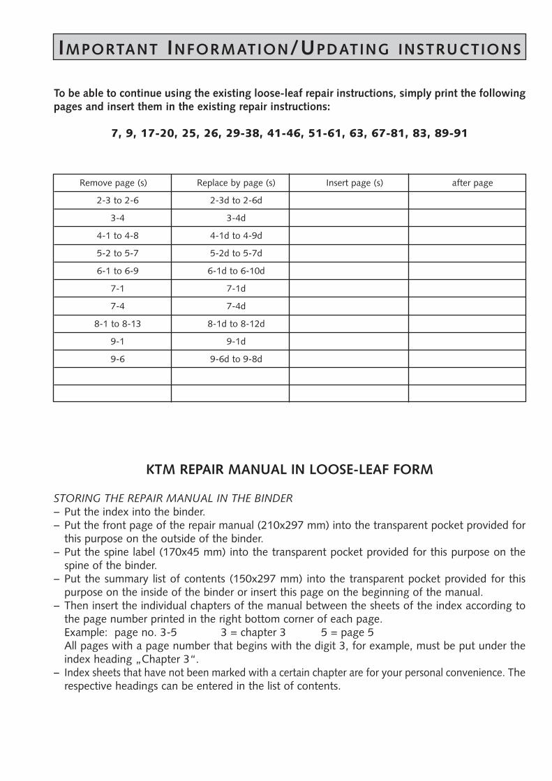
IMPORTANT INFORMATION/UPDATING INSTRUCTIONS
To be able to continue using the existing loose-leaf repair instructions, simply print the followingpages and insert them in the existing repair instructions:
7, 9, 17-20, 25, 26, 29-38, 41-46, 51-61, 63, 67-81, 83, 89-91
KTM REPAIR MANUAL IN LOOSE-LEAF FORM
STORING THE REPAIR MANUAL IN THE BINDER– Put the index into the binder.– Put the front page of the repair manual (210x297 mm) into the transparent pocket provided for
this purpose on the outside of the binder.– Put the spine label (170x45 mm) into the transparent pocket provided for this purpose on the
spine of the binder.– Put the summary list of contents (150x297 mm) into the transparent pocket provided for this
purpose on the inside of the binder or insert this page on the beginning of the manual.– Then insert the individual chapters of the manual between the sheets of the index according to
the page number printed in the right bottom corner of each page. Example: page no. 3-5 3 = chapter 3 5 = page 5All pages with a page number that begins with the digit 3, for example, must be put under theindex heading „Chapter 3“.
– Index sheets that have not been marked with a certain chapter are for your personal convenience. Therespective headings can be entered in the list of contents.

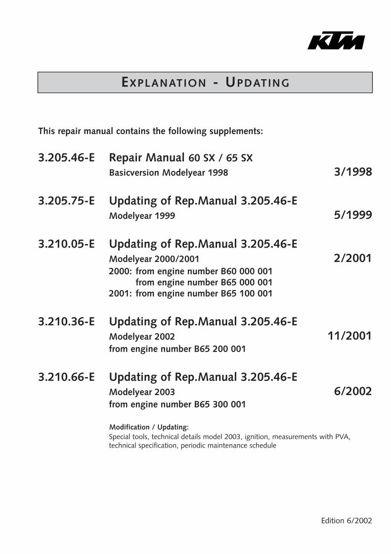
EXPLANATION - UPDATING
Edition 6/2002
This repair manual contains the following supplements:
3.205.46-E Repair Manual 60 SX / 65 SXBasicversion Modelyear 1998 3/1998
3.205.75-E Updating of Rep.Manual 3.205.46-EModelyear 1999 5/1999
3.210.05-E Updating of Rep.Manual 3.205.46-EModelyear 2000/2001 2/20012000: from engine number B60 000 001
from engine number B65 000 0012001: from engine number B65 100 001
3.210.36-E Updating of Rep.Manual 3.205.46-EModelyear 2002 11/2001from engine number B65 200 001
3.210.66-E Updating of Rep.Manual 3.205.46-EModelyear 2003 6/2002from engine number B65 300 001
Modification / Updating:Special tools, technical details model 2003, ignition, measurements with PVA,technical specification, periodic maintenance schedule

INTRODUCTION
This repair manual offers extensiv repair-instructions and is an up-to-date version that describes thelatest models of the series. However, the right to modifications in the interest of technical improvement is reserved without updating the current issue of this manual.
A description of general working modes common in work shops has not been included. Safety rulescommon in the work shop have also not been listed. We take it for granted that the repairs are madeby qualified profesionally trained mechanics.
Read through the repair manual before beginning with the repair work.
WARNING STRICT COMPLIANCE WITH THESE INSTRUCTIONS IS ESSENTIAL TO AVOID DANGER TO LIFE AND LIMB.
! CAUTION !
NON-COMPLIANCE WITH THESE INSTRUCTIONS CAN LEAD TODAMAGE OF MOTORCYCLE COMPONENTS OR RENDERMOTORCYCLES UNFIT FOR TRAFFIC !
„NOTE” POINTS OUT USEFUL TIPS.
Use only ORIGINAL KTM SPARE PARTS when replacing parts.
The KTM high performance engine is only able to meet user expectations if the maintenance work isperformed regularly and professionally.
KTM Austria’s certificate of achievement for its quality system ISO 9001 is the beginning of an ongoing total reengineered quality plan for a brighter tomorrow.
KTM Sportmotorcycle AG5230 Mattighofen, Austria
All design and assembly modification rights reserved.
C by KTM SPORTMOTORCYCLE AG, AUSTRIA All rights reserved

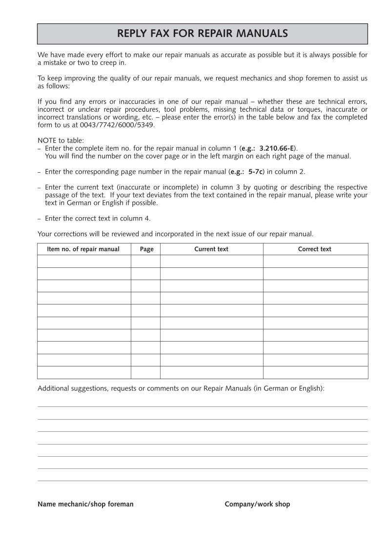
REPLY FAX FOR REPAIR MANUALS
We have made every effort to make our repair manuals as accurate as possible but it is always possible fora mistake or two to creep in.
To keep improving the quality of our repair manuals, we request mechanics and shop foremen to assist usas follows:
If you find any errors or inaccuracies in one of our repair manual – whether these are technical errors, incorrect or unclear repair procedures, tool problems, missing technical data or torques, inaccurate or incorrect translations or wording, etc. – please enter the error(s) in the table below and fax the completedform to us at 0043/7742/6000/5349.
NOTE to table:– Enter the complete item no. for the repair manual in column 1 (e.g.: 3.210.66-E).
You will find the number on the cover page or in the left margin on each right page of the manual.
– Enter the corresponding page number in the repair manual (e.g.: 5-7c) in column 2.
– Enter the current text (inaccurate or incomplete) in column 3 by quoting or describing the respective passage of the text. If your text deviates from the text contained in the repair manual, please write yourtext in German or English if possible.
– Enter the correct text in column 4.
Your corrections will be reviewed and incorporated in the next issue of our repair manual.
Item no. of repair manual Page Current text Correct text
Additional suggestions, requests or comments on our Repair Manuals (in German or English):
Name mechanic/shop foreman Company/work shop

GENERAL INFORMATION
CARBURETOR ADJUSTMENT . . . . . . . . . . . . . . . . . . . . . . . . . . . . . . . . .2-2
BLEEDING OF THE HYDRAULIC CLUTCH . . . . . . . . . . . . . . . . . . . . . . . . .2-3
SPECIAL TOOLS . . . . . . . . . . . . . . . . . . . . . . . . . . . . . . . . . . . . . . . . . . . .2-4
CLEANING . . . . . . . . . . . . . . . . . . . . . . . . . . . . . . . . . . . . . . . . . . . . . . . .2-6
STORAGE . . . . . . . . . . . . . . . . . . . . . . . . . . . . . . . . . . . . . . . . . . . . . . . . .2-6
INDEX
2R
epai
r m
anua
l K
TM 6
0 SX
+ 6
5 SX
A
rt.-
No.
32
1066
-E
2-1d
2-2d
B
C
D
A
main jetjet needle
jet needle
idling jet
idling jetthrottle valve
Carburetor adjustmentBasic information about the original carburetor settingThe original carburetor setting was adapted for an altitude of approx. 500 meters (1600 ft.) above sea level, and the ambient temperature of approx. 20° C (68° F), mainly for off-road use and central European premium-grade fuel (ROZ 95). Mixing ratio 2-stroke motor oil : super fuel 1:40 .Basic information of changing the carburetor settingAlways start out from the original carburetor setting. Essential requirements are a clean air filter system, air-tight exhaust system andan intact carburetor. Experience has shown that adjusting the main jet, the idling jet and the jet needle is sufficient and that changes of other parts of the carburetor will not greatly affect engine performance.RULE OF THUMB: high altitude or high temperatures choose leaner carburetor adjustment
low altitude or low temperatures choose richer carburetor adjustment
WARNING – ONLY USE PREMIUM-GRADE GASOLINE ROZ 95 MIXED WITH HIGH-GRADE TWO-STROKE ENGINE OIL. OTHER TYPES OF GASOLINE CAN CAUSE ENGINE
FAILURE, AND USE OF SAME WILL VOID YOUR WARRANTY.– ONLY USE HIGH-GRADE 2-STROKE ENGINE OIL OF KNOWN BRANDS (I. E. SHELL ADVANCE RACING X).– NOT ENOUGH OIL OR LOW-GRADE OIL CAN CAUSE EROSION OF THE PISTON. USING TOO MUCH OIL, THE ENGINE CAN START SMOKING AND FOUL THE
SPARK PLUG.– IN THE CASE OF A LEANER ADJUSTMENT OF THE CARBURETOR PROCEED CAUTIOUSLY. ALWAYS REDUCE THE JET SIZE IN STEPS OF ONE NUMBER TO AVOID
OVERHEATING AND PISTON SEIZURE.
NOTE: If despite a changed adjustment the engine does not run properly, look for mechanical faults and check the ignition system.
Basic information on carburetor wearAs a result of engine vibrations, throttle valve, jet needle, and needle jet are subjected to increased wear. This wear may cause carburetor malfunction (e.g., overly rich mixture). Therefore, these parts should be replaced after 1000 hours of using.
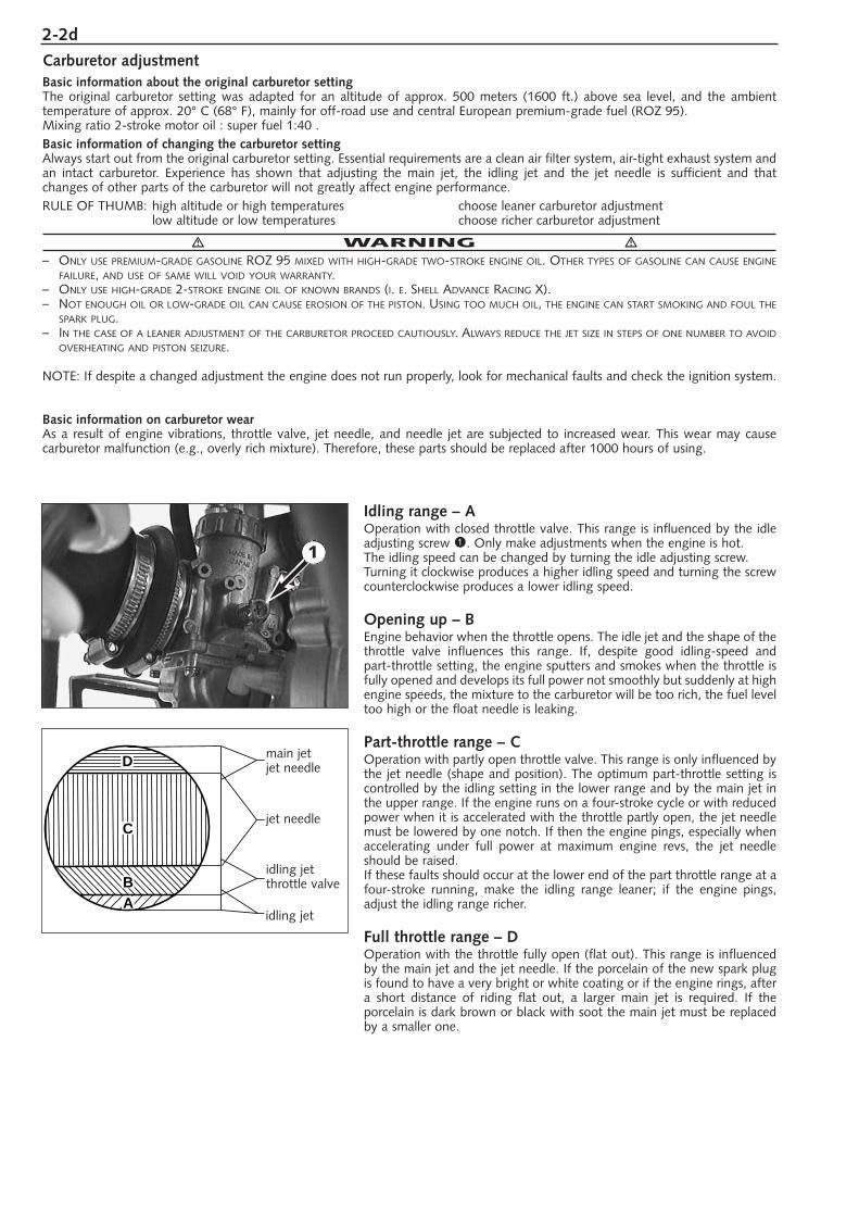
Idling range – AOperation with closed throttle valve. This range is influenced by the idleadjusting screw 1. Only make adjustments when the engine is hot.The idling speed can be changed by turning the idle adjusting screw.Turning it clockwise produces a higher idling speed and turning the screwcounterclockwise produces a lower idling speed.
Opening up – BEngine behavior when the throttle opens. The idle jet and the shape of thethrottle valve influences this range. If, despite good idling-speed and part-throttle setting, the engine sputters and smokes when the throttle isfully opened and develops its full power not smoothly but suddenly at highengine speeds, the mixture to the carburetor will be too rich, the fuel leveltoo high or the float needle is leaking.
Part-throttle range – COperation with partly open throttle valve. This range is only influenced bythe jet needle (shape and position). The optimum part-throttle setting iscontrolled by the idling setting in the lower range and by the main jet inthe upper range. If the engine runs on a four-stroke cycle or with reducedpower when it is accelerated with the throttle partly open, the jet needlemust be lowered by one notch. If then the engine pings, especially whenaccelerating under full power at maximum engine revs, the jet needleshould be raised.If these faults should occur at the lower end of the part throttle range at afour-stroke running, make the idling range leaner; if the engine pings,adjust the idling range richer.
Full throttle range – DOperation with the throttle fully open (flat out). This range is influencedby the main jet and the jet needle. If the porcelain of the new spark plugis found to have a very bright or white coating or if the engine rings, aftera short distance of riding flat out, a larger main jet is required. If the porcelain is dark brown or black with soot the main jet must be replacedby a smaller one.
1
2-3dR
epai
r m
anua
l K
TM 6
0 SX
+ 6
5 SX
A
rt.-
No.
32
1066
-E
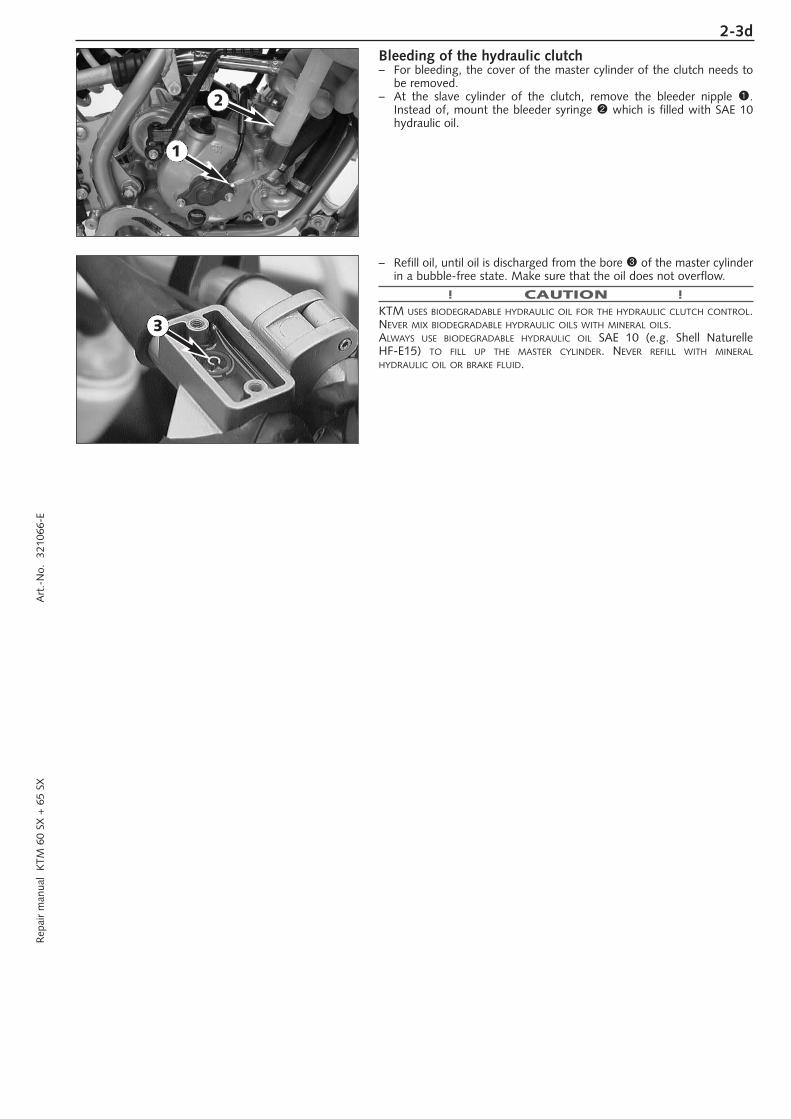
Bleeding of the hydraulic clutch– For bleeding, the cover of the master cylinder of the clutch needs to
be removed.– At the slave cylinder of the clutch, remove the bleeder nipple 1.
Instead of, mount the bleeder syringe 2 which is filled with SAE 10hydraulic oil.
– Refill oil, until oil is discharged from the bore 3 of the master cylinderin a bubble-free state. Make sure that the oil does not overflow.
! CAUTION !KTM USES BIODEGRADABLE HYDRAULIC OIL FOR THE HYDRAULIC CLUTCH CONTROL.NEVER MIX BIODEGRADABLE HYDRAULIC OILS WITH MINERAL OILS.ALWAYS USE BIODEGRADABLE HYDRAULIC OIL SAE 10 (e.g. Shell Naturelle HF-E15) TO FILL UP THE MASTER CYLINDER. NEVER REFILL WITH MINERALHYDRAULIC OIL OR BRAKE FLUID.
1
2
3
2-4d
15
50
8
130
75
140
27
175
60
1
2
3 4
5 6 7 8
1110
ignition
cylinder height
1213
14
9
2-5dR
epai
r m
anua
l K
TM 6
0 SX
+ 6
5 SX
A
rt.-
No.
32
1066
-E
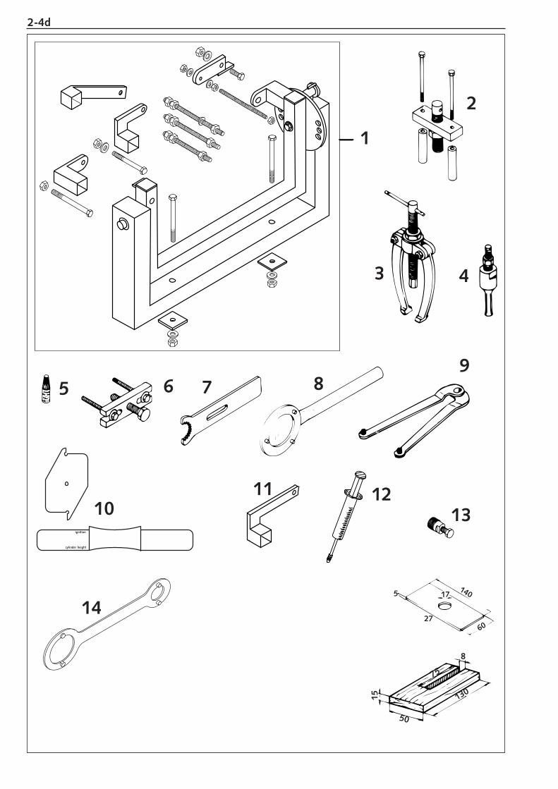
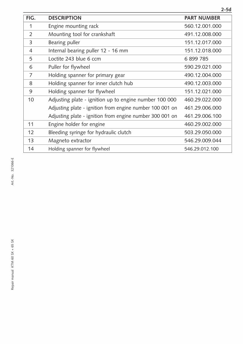
FIG. DESCRIPTION PART NUMBER
1 Engine mounting rack 560.12.001.000
2 Mounting tool for crankshaft 491.12.008.000
3 Bearing puller 151.12.017.000
4 Internal bearing puller 12 - 16 mm 151.12.018.000
5 Loctite 243 blue 6 ccm 6 899 785
6 Puller for flywheel 590.29.021.000
7 Holding spanner for primary gear 490.12.004.000
8 Holding spanner for inner clutch hub 490.12.003.000
9 Holding spanner for flywheel 151.12.021.000
10 Adjusting plate - ignition up to engine number 100 000 460.29.022.000
Adjusting plate - ignition from engine number 100 001 on 461.29.006.000
Adjusting plate - ignition from engine number 300 001 on 461.29.006.100
11 Engine holder for engine 460.29.002.000
12 Bleeding syringe for hydraulic clutch 503.29.050.000
13 Magneto extractor 546.29.009.044
14 Holding spanner for flywheel 546.29.012.100
2-6d
Clean your motorcycle regularly in order to keep its painted finish looking shiny and new.The best manner would be to use warm water that has been mixed with a commercially available washing detergent and a sponge.The hard dirt can be removed before with the help of a soft water jet.
! CAUTION !NEVER CLEAN YOUR MOTORCYCLE WITH A HIGH-PRESSURED CLEANER OR A HIGH-PRESSURED WATER JET. OTHERWISE WATER MIGHT RUN INTO ELECTRICALCOMPONENTS, CONNECTORS, SHEATHED CABLES, BEARINGS, CARBURETOR ETC. AND CAUSE MAILFUNCTIONS, I.E., LEAD TO THE PREMATURE DESTRUCTIONOF THESE PARTS.
– You should use commercially available detergents to clean the motorcycle. Heavily soiled parts should also be cleaned with thehelp of a paint brush.
– Befor cleaning with water, plug the exhaust pipe to prevent water ingress.– After the motorcycle has been rinsed with a soft water jet, it should be dried by air pressure and a cloth. Then take a short drive
until the engine has reached its operating temperature, and also operate the brakes. The heat also causes the water at the inaccessible parts of the engine and the brakes to evaporate.
– Slide back the protective covers on the handlebar-mounted instruments so that any water that may have seeped into this part ofthe motorcycle is allowed to evaporate.
– After the motorcycle has cooled down, oil and grease all the gliding bearing parts. Also treat the chain with a chain spray.– To prevent failures in the electric system, you should treat the short circuit button with a contact spray.
If you want to put your motorcycle away for longer periods of time, please observe the following instructions:
– Clean motorcycle thoroughly (see chapter: CLEANING)– Change engine oil (old engine oil contains aggresive contaminations).– Check antifreeze and amount of cooling liquid.– Let the engine warm up again, close fuel tap and wait until the engine dies off by itself. In this way, the carburetor jets are
prevented from becoming resin-clogged by the old fuel.– Remove spark plug and fill in approx. 5 ccm of engine oil into the cylinder through the opening. Actuate kick-starter 10 times in
order to distribute the oil onto the cylinder walls and mount the spark plug.– Let fuel flow out of tank into an appropriate basin.– Correct tire pressure.– Lubricate bearing points of the control levers, foot rests, etc. as well as the chain.– The storage place should be dry and not be subject to overly great temperature fluctuations.– Cover the motorcycle with an air permeable tarpaulin or blanket. Do not use non-air-permeable materials, as possible humidity
might not be able to escape and thereby cause corrosion.
! CAUTION !IT WOULD BE VERY BAD TO LET THE ENGINE RUN FOR A SHORT TIME DURING THE STORAGE PERIOD. THE ENGINE WOULD NOT GET WARMED UP ENOUGHAND THE THUS DEVELOPED STEAM WOULD CONDENSE DURING THE COMBUSTION PROCESS AND CAUSE THE EXHAUST TO RUST.
USE AFTER PERIOD OF STORAGE– Fill up tank with fresh fuel.– Check motorcycle as before each start (see driving instructions)– Take a short, careful test ride first.
CLEANING
STORAGE
REMOVING AND REFITTING ENGINE
REMOVING ENGINE . . . . . . . . . . . . . . . . . . . . . . . . . . . . . . . . . . . . . . . . .3-2
REFITTING ENGINE . . . . . . . . . . . . . . . . . . . . . . . . . . . . . . . . . . . . . . . . . .3-5
INDEX
3R
epai
r m
anua
l K
TM 6
0 SX
+ 6
5 SX
A
rt.-
No.
32
1066
-E
3-1d

3-2dR
epai
r m
anua
l K
TM 6
0 SX
+ 6
5 SX
A
rt.-
No.
32
1066
-E
1
2
2
3
4
4
5
6
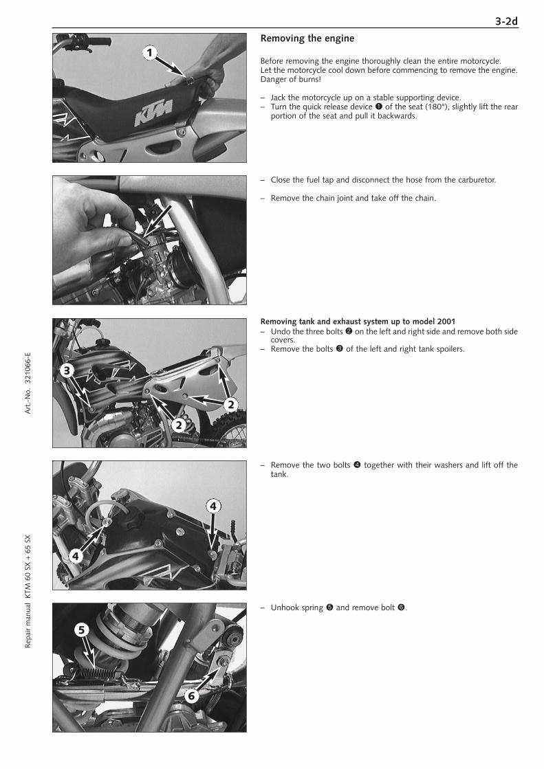
Removing the engine
Before removing the engine thoroughly clean the entire motorcycle.Let the motorcycle cool down before commencing to remove the engine.Danger of burns!
– Jack the motorcycle up on a stable supporting device.– Turn the quick release device 1 of the seat (180°), slightly lift the rear
portion of the seat and pull it backwards.
– Close the fuel tap and disconnect the hose from the carburetor.
– Remove the chain joint and take off the chain.
Removing tank and exhaust system up to model 2001– Undo the three bolts 2 on the left and right side and remove both side
covers.– Remove the bolts 3 of the left and right tank spoilers.
– Remove the two bolts 4 together with their washers and lift off thetank.
– Unhook spring 5 and remove bolt 6.
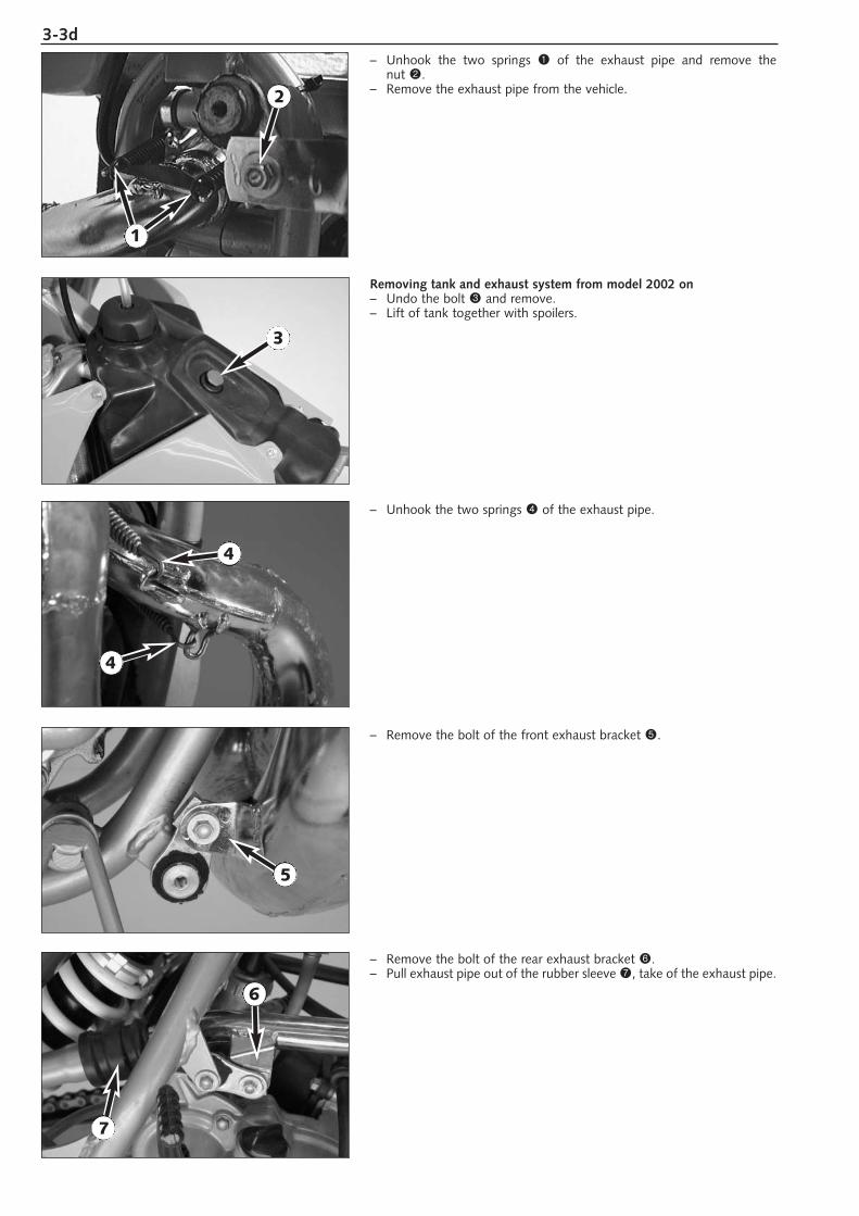
3-3d– Unhook the two springs 1 of the exhaust pipe and remove the
nut 2.– Remove the exhaust pipe from the vehicle.
Removing tank and exhaust system from model 2002 on– Undo the bolt 3 and remove.– Lift of tank together with spoilers.
– Unhook the two springs 4 of the exhaust pipe.
– Remove the bolt of the front exhaust bracket 5.
– Remove the bolt of the rear exhaust bracket 6.– Pull exhaust pipe out of the rubber sleeve 7, take of the exhaust pipe.
1
2
3
4
4
5
6
7
3-4dR
epai
r m
anua
l K
TM 6
0 SX
+ 6
5 SX
A
rt.-
No.
32
1066
-E
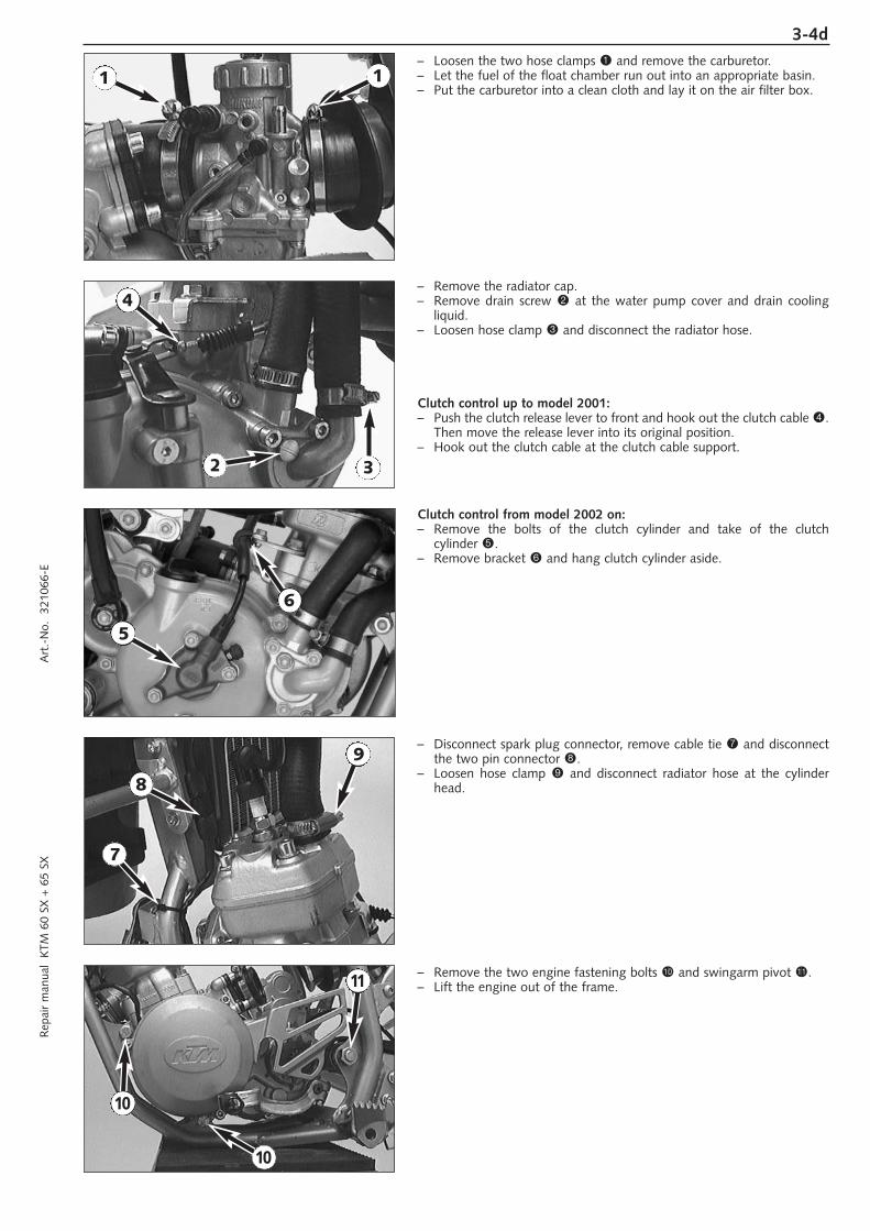
– Loosen the two hose clamps 1 and remove the carburetor.– Let the fuel of the float chamber run out into an appropriate basin.– Put the carburetor into a clean cloth and lay it on the air filter box.
– Remove the radiator cap.– Remove drain screw 2 at the water pump cover and drain cooling
liquid.– Loosen hose clamp 3 and disconnect the radiator hose.
Clutch control up to model 2001:– Push the clutch release lever to front and hook out the clutch cable 4.
Then move the release lever into its original position.– Hook out the clutch cable at the clutch cable support.
Clutch control from model 2002 on:– Remove the bolts of the clutch cylinder and take of the clutch
cylinder 5.– Remove bracket 6 and hang clutch cylinder aside.
– Disconnect spark plug connector, remove cable tie 7 and disconnectthe two pin connector 8.
– Loosen hose clamp 9 and disconnect radiator hose at the cylinderhead.
– Remove the two engine fastening bolts bk and swingarm pivot bl.– Lift the engine out of the frame.
1 1
2 3
4
5
6
7
8
9
10
10
11
3-5d
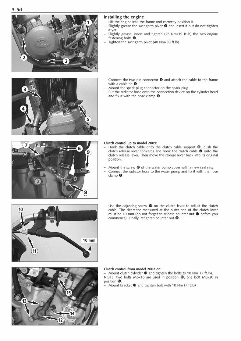
Installing the engine– Lift the engine into the frame and correctly position it.– Slightly grease the swingarm pivot 1 and insert it but do not tighten
it yet.– Slightly grease, insert and tighten (25 Nm/19 ft.lb) the two engine
fastening bolts 2.– Tighten the swingarm pivot (40 Nm/30 ft.lb).
– Connect the two pin connector 3 and attach the cable to the framewith a cable tie 4.
– Mount the spark plug connector on the spark plug.– Put the radiator hose onto the connection device on the cylinder head
and fix it with the hose clamp 5.
Clutch control up to model 2001:– Hook the clutch cable onto the clutch cable support 6, push the
clutch release lever forwards and hook the clutch cable 7 onto theclutch release lever. Then move the release lever back into its originalposition.
– Mount the screw 8 of the water pump cover with a new seal ring.– Connect the radiator hose to the water pump and fix it with the hose
clamp 9.
– Use the adjusting screw bk on the clutch lever to adjust the clutchcable. The clearance measured at the outer end of the clutch levermust be 10 mm (do not forget to release counter nut bl before youcommence). Finally, retighten counter nut bl.
Clutch control from model 2002 on:– Mount clutch cylinder bm and tighten the bolts to 10 Nm (7 ft.lb).NOTE: two bolts M6x16 are used in position bn, one bolt M6x20 in position bo.– Mount bracket bp and tighten bolt with 10 Nm (7 ft.lb)
10 mm
1
22
3
4
5
67
8
9
10
11
12
13
14
15
3-6dR
epai
r m
anua
l K
TM 6
0 SX
+ 6
5 SX
A
rt.-
No.
32
1066
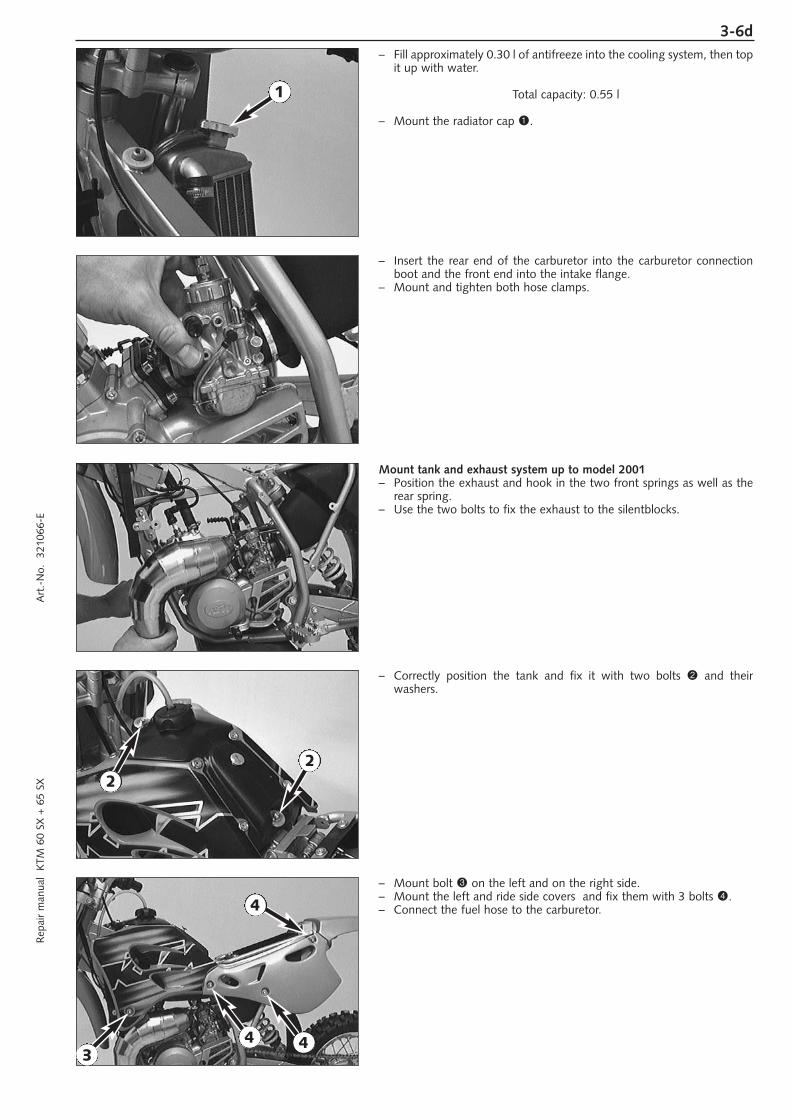
-E– Fill approximately 0.30 l of antifreeze into the cooling system, then top
it up with water.
Total capacity: 0.55 l
– Mount the radiator cap 1.
– Insert the rear end of the carburetor into the carburetor connectionboot and the front end into the intake flange.
– Mount and tighten both hose clamps.
Mount tank and exhaust system up to model 2001– Position the exhaust and hook in the two front springs as well as the
rear spring.– Use the two bolts to fix the exhaust to the silentblocks.
– Correctly position the tank and fix it with two bolts 2 and their washers.
– Mount bolt 3 on the left and on the right side.– Mount the left and ride side covers and fix them with 3 bolts 4.– Connect the fuel hose to the carburetor.
3
1
22
4
4
4
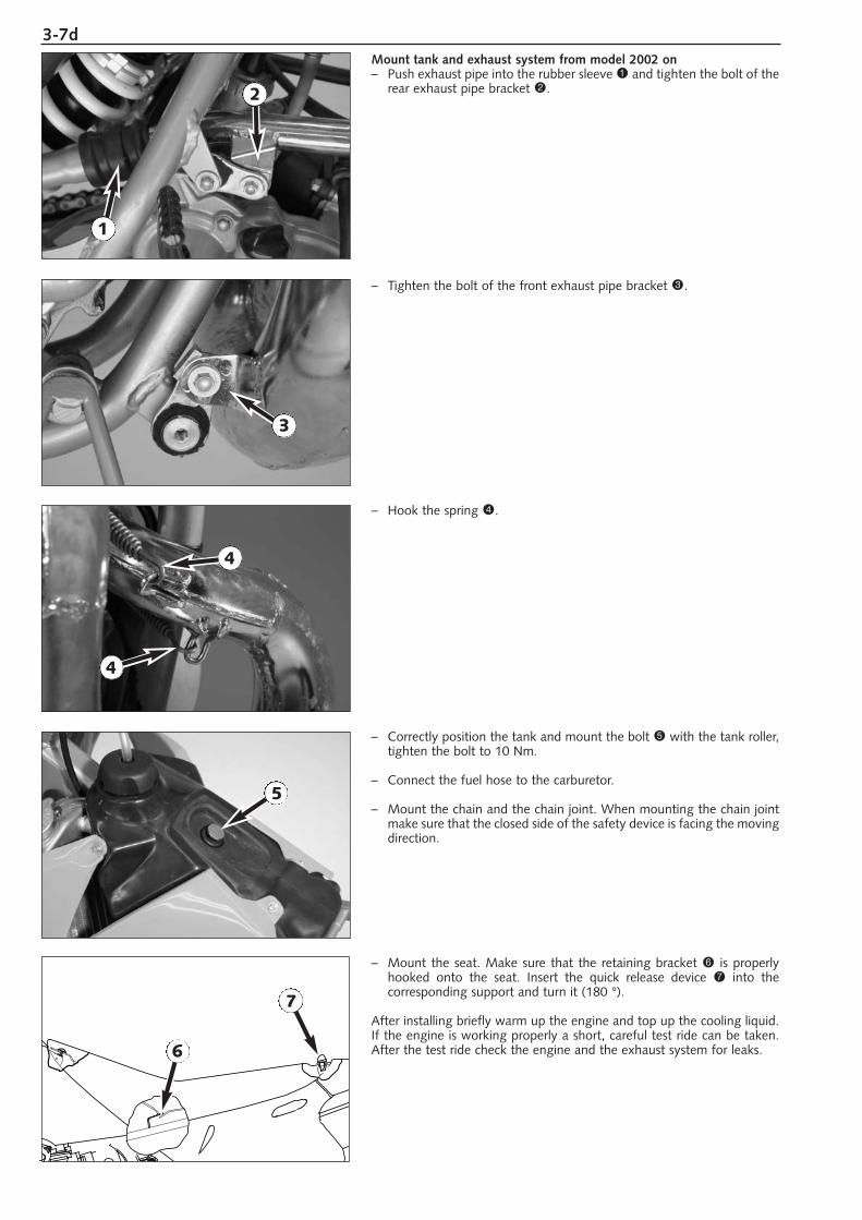
3-7dMount tank and exhaust system from model 2002 on– Push exhaust pipe into the rubber sleeve 1 and tighten the bolt of the
rear exhaust pipe bracket 2.
– Tighten the bolt of the front exhaust pipe bracket 3.
– Hook the spring 4.
– Correctly position the tank and mount the bolt 5 with the tank roller,tighten the bolt to 10 Nm.
– Connect the fuel hose to the carburetor.
– Mount the chain and the chain joint. When mounting the chain jointmake sure that the closed side of the safety device is facing the movingdirection.
– Mount the seat. Make sure that the retaining bracket 6 is properlyhooked onto the seat. Insert the quick release device 7 into the corresponding support and turn it (180 °).
After installing briefly warm up the engine and top up the cooling liquid.If the engine is working properly a short, careful test ride can be taken.After the test ride check the engine and the exhaust system for leaks.
4
4
1
2
3
5
6
7
DISASSEMBLING THE ENGINE
CLAMP THE ENGINE INTO THE MOUNTING RACK,
REMOVING OF KICKSTARTER AND SHIFT LEVER . . . . . . . . . . . . . . . . . . .4-2
DRAINING GEAR OIL . . . . . . . . . . . . . . . . . . . . . . . . . . . . . . . . . . . . . . . .4-2
DISMOUNT OF CYLINDER HEAD, CYLINDER AND PISTON . . . . . . . . . . .4-2
DISMANTLE THE WATER PUMP . . . . . . . . . . . . . . . . . . . . . . . . . . . . . . . .4-3
REMOVE THE CLUTCH COVER . . . . . . . . . . . . . . . . . . . . . . . . . . . . . . . .4-3
DISMANTLE CLUTCH . . . . . . . . . . . . . . . . . . . . . . . . . . . . . . . . . . . . . . . .4-4
PRIMARY DRIVE . . . . . . . . . . . . . . . . . . . . . . . . . . . . . . . . . . . . . . . . . . . .4-4
REMOVE KICKSTARTER SHAFT . . . . . . . . . . . . . . . . . . . . . . . . . . . . . . . . .4-5
REMOVE SHIFT SHAFT AND SHIFTING MECHANISM . . . . . . . . . . . . . . . .4-5
REMOVE INTAKE FLANGE AND REED VALVE HOUSING . . . . . . . . . . . . . .4-6
REMOVE IGNITION SYSTEM UP TO MODEL 2002 . . . . . . . . . . . . . . . . . .4-6
REMOVE IGNITION SYSTEM FROM MODEL 2003 . . . . . . . . . . . . . . . . . .4-7
REMOVING THE ENGINE SPROCKET . . . . . . . . . . . . . . . . . . . . . . . . . . . .4-8
SEPARATING THE HOUSING HALVES . . . . . . . . . . . . . . . . . . . . . . . . . . . .4-8
REMOVING THE TRANSMISSION SHAFTS . . . . . . . . . . . . . . . . . . . . . . . .4-8
REMOVING THE CRANKSHAFT OF THE ENGINE HOUSING . . . . . . . . . . .4-9
INDEX
4R
epai
r m
anua
l K
TM 6
0 SX
+ 6
5 SX
A
rt.-
No.
32
1066
-E
4-1d

4-2dR
epai
r m
anua
l K
TM 6
0 SX
+ 6
5 SX
A
rt.-
No.
32
1066
-E
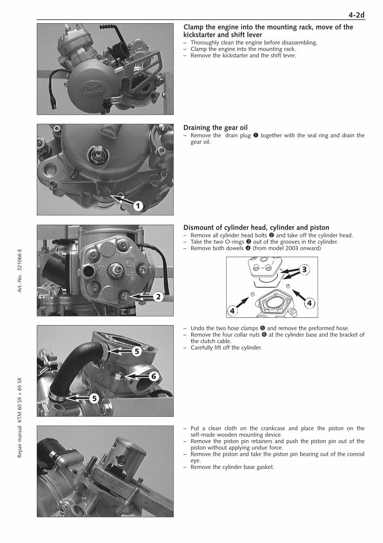
Clamp the engine into the mounting rack, move of thekickstarter and shift lever– Thoroughly clean the engine before disassembling.– Clamp the engine into the mounting rack.– Remove the kickstarter and the shift lever.
Draining the gear oil– Remove the drain plug 1 together with the seal ring and drain the
gear oil.
Dismount of cylinder head, cylinder and piston– Remove all cylinder head bolts 2 and take off the cylinder head.– Take the two O-rings 3 out of the grooves in the cylinder.– Remove both dowels 4 (from model 2003 onward)
– Undo the two hose clamps 5 and remove the preformed hose.– Remove the four collar nuts 6 at the cylinder base and the bracket of
the clutch cable.– Carefully lift off the cylinder.
– Put a clean cloth on the crankcase and place the piston on the self-made wooden mounting device.
– Remove the piston pin retainers and push the piston pin out of thepiston without applying undue force.
– Remove the piston and take the piston pin bearing out of the conrodeye.
– Remove the cylinder base gasket.
1
2
5
5
6
44
3
4-3d
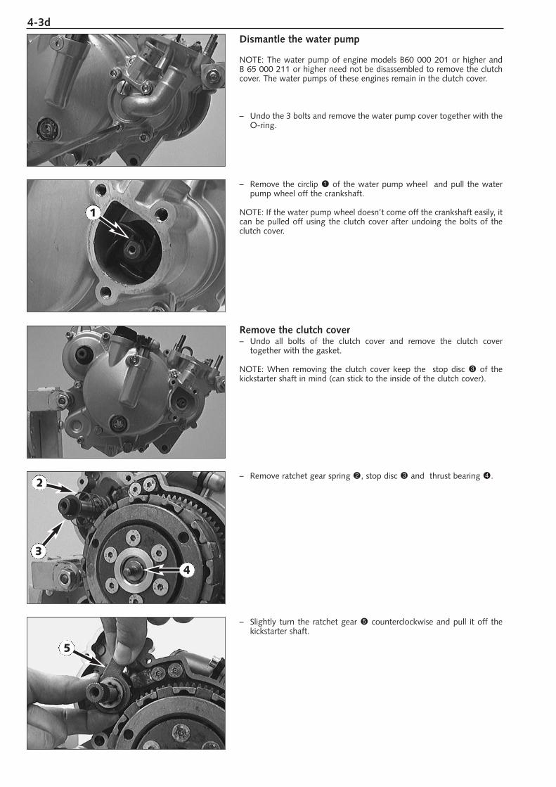
Dismantle the water pump
NOTE: The water pump of engine models B60 000 201 or higher and B 65 000 211 or higher need not be disassembled to remove the clutchcover. The water pumps of these engines remain in the clutch cover.
– Undo the 3 bolts and remove the water pump cover together with theO-ring.
– Remove the circlip 1 of the water pump wheel and pull the waterpump wheel off the crankshaft.
NOTE: If the water pump wheel doesn’t come off the crankshaft easily, itcan be pulled off using the clutch cover after undoing the bolts of theclutch cover.
Remove the clutch cover– Undo all bolts of the clutch cover and remove the clutch cover
together with the gasket.
NOTE: When removing the clutch cover keep the stop disc 3 of thekickstarter shaft in mind (can stick to the inside of the clutch cover).
– Remove ratchet gear spring 2, stop disc 3 and thrust bearing 4.
– Slightly turn the ratchet gear 5 counterclockwise and pull it off thekickstarter shaft.
1
2
3
4
5
4-4dR
epai
r m
anua
l K
TM 6
0 SX
+ 6
5 SX
A
rt.-
No.
32
1066
-E
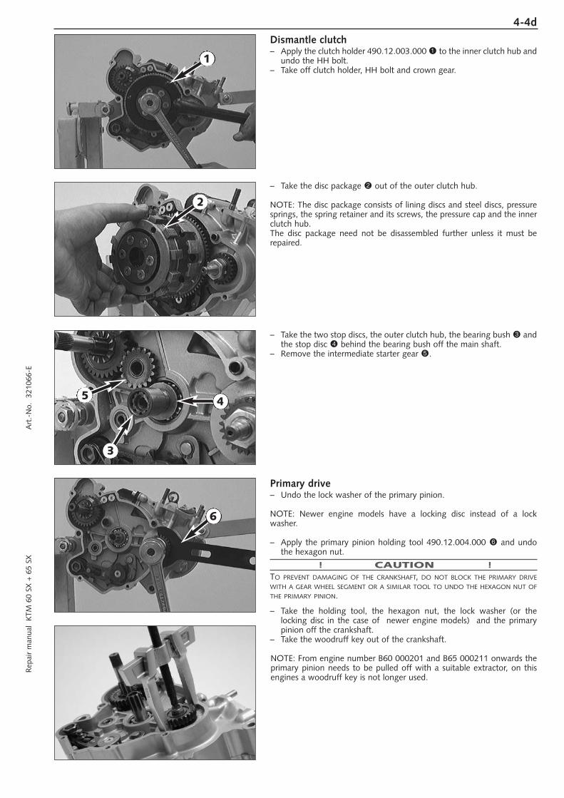
Dismantle clutch– Apply the clutch holder 490.12.003.000 1 to the inner clutch hub and
undo the HH bolt.– Take off clutch holder, HH bolt and crown gear.
– Take the disc package 2 out of the outer clutch hub.
NOTE: The disc package consists of lining discs and steel discs, pressuresprings, the spring retainer and its screws, the pressure cap and the innerclutch hub.The disc package need not be disassembled further unless it must berepaired.
– Take the two stop discs, the outer clutch hub, the bearing bush 3 andthe stop disc 4 behind the bearing bush off the main shaft.
– Remove the intermediate starter gear 5.
Primary drive– Undo the lock washer of the primary pinion.
NOTE: Newer engine models have a locking disc instead of a lock washer.
– Apply the primary pinion holding tool 490.12.004.000 6 and undothe hexagon nut.
! CAUTION !TO PREVENT DAMAGING OF THE CRANKSHAFT, DO NOT BLOCK THE PRIMARY DRIVEWITH A GEAR WHEEL SEGMENT OR A SIMILAR TOOL TO UNDO THE HEXAGON NUT OFTHE PRIMARY PINION.
– Take the holding tool, the hexagon nut, the lock washer (or thelocking disc in the case of newer engine models) and the primarypinion off the crankshaft.
– Take the woodruff key out of the crankshaft.
NOTE: From engine number B60 000201 and B65 000211 onwards theprimary pinion needs to be pulled off with a suitable extractor, on thisengines a woodruff key is not longer used.
4
2
3
6
1
5
4-5d
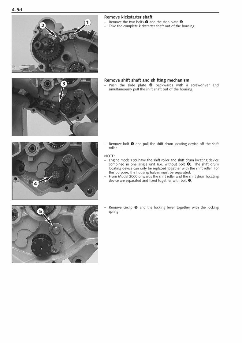
Remove kickstarter shaft– Remove the two bolts 1 and the stop plate 2. – Take the complete kickstarter shaft out of the housing.
Remove shift shaft and shifting mechanism– Push the slide plate 3 backwards with a screwdriver and
simultaneously pull the shift shaft out of the housing.
– Remove bolt 4 and pull the shift drum locating device off the shiftroller.
NOTE:– Engine models 99 have the shift roller and shift drum locating device
combined in one single unit (i.e. without bolt 4). The shift drum locating device can only be replaced together with the shift roller. Forthis purpose, the housing halves must be separated.
– From Model 2000 onwards the shift roller and the shift drum locatingdevice are separated and fixed together with bolt 4.
– Remove circlip 5 and the locking lever together with the lockingspring.
12
3
4
5
4-6dR
epai
r m
anua
l K
TM 6
0 SX
+ 6
5 SX
A
rt.-
No.
32
1066
-E
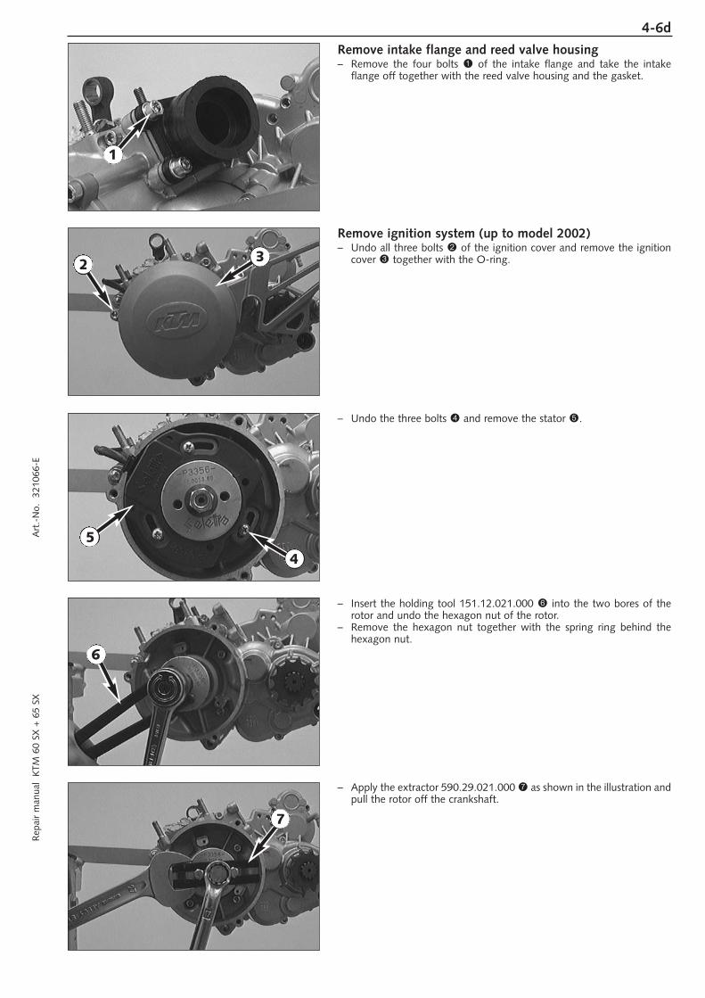
Remove intake flange and reed valve housing– Remove the four bolts 1 of the intake flange and take the intake
flange off together with the reed valve housing and the gasket.
Remove ignition system (up to model 2002)– Undo all three bolts 2 of the ignition cover and remove the ignition
cover 3 together with the O-ring.
– Undo the three bolts 4 and remove the stator 5.
– Insert the holding tool 151.12.021.000 6 into the two bores of therotor and undo the hexagon nut of the rotor.
– Remove the hexagon nut together with the spring ring behind thehexagon nut.
– Apply the extractor 590.29.021.000 7 as shown in the illustration andpull the rotor off the crankshaft.
1
2 3
4
5
6
7
4-7d
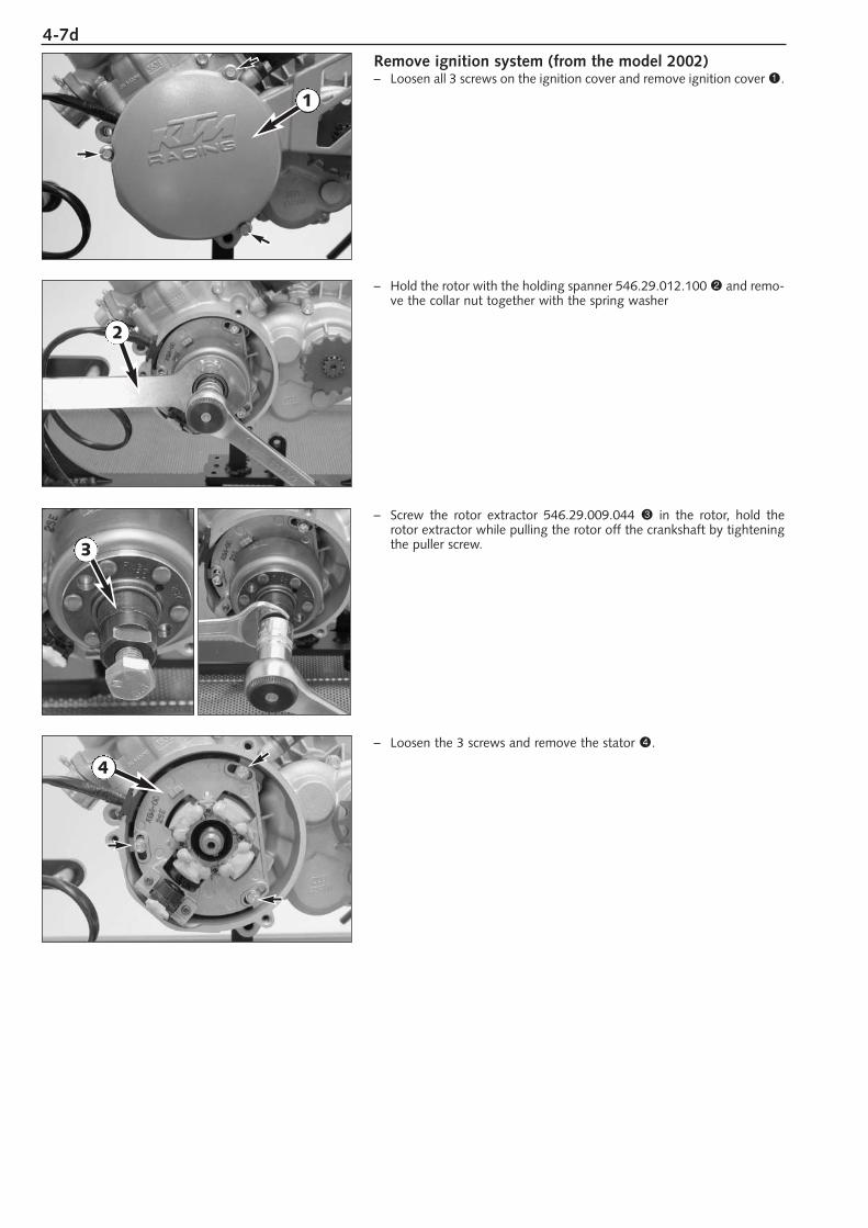
Remove ignition system (from the model 2002)– Loosen all 3 screws on the ignition cover and remove ignition cover 1.
– Hold the rotor with the holding spanner 546.29.012.100 2 and remo-ve the collar nut together with the spring washer
– Screw the rotor extractor 546.29.009.044 3 in the rotor, hold therotor extractor while pulling the rotor off the crankshaft by tighteningthe puller screw.
– Loosen the 3 screws and remove the stator 4.
2
1
3
4
4-8dR
epai
r m
anua
l K
TM 6
0 SX
+ 6
5 SX
A
rt.-
No.
32
1066
-E
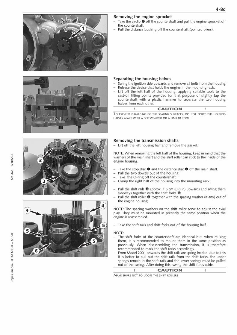
Removing the engine sprocket– Take the circlip 1 off the countershaft and pull the engine sprocket off
the countershaft.– Pull the distance bushing off the countershaft (pointed pliers).
Separating the housing halves– Swing the ignition side upwards and remove all bolts from the housing– Release the device that holds the engine in the mounting rack.– Lift off the left half of the housing, applying suitable tools to the
cast-on lifting points provided for that purpose or slightly tap thecountershaft with a plastic hammer to separate the two housing halves from each other.
! CAUTION !TO PREVENT DAMAGING OF THE SEALING SURFACES, DO NOT FORCE THE HOUSINGHALVES APART WITH A SCREWDRIVER OR A SIMILAR TOOL.
Removing the transmission shafts– Lift off the left housing half and remove the gasket.
NOTE: When removing the left half of the housing, keep in mind that thewashers of the main shaft and the shift roller can stick to the inside of theengine housing.
– Take the stop disc 3 and the distance disc 2 off the main shaft.– Pull the two dowels out of the housing.– Take the O-ring off the countershaft.– Clamp the right half of the housing into the mounting rack.
– Pull the shift rails 4 approx. 1.5 cm (0.6 in) upwards and swing themsideways together with the shift forks 5.
– Pull the shift roller 6 together with the spacing washer (if any) out ofthe engine housing.
NOTE: The spacing washers on the shift roller serve to adjust the axialplay. They must be mounted in precisely the same position when theengine is reassembled.
– Take the shift rails and shift forks out of the housing half.
NOTE:– The shift forks of the countershaft are identical but, when reusing
them, it is recommended to mount them in the same position as previously. When disassembling the transmission, it is therefore recommended to mark the shift forks accordingly.
– From Model 2001 onwards the shift rails are spring loaded, due to thisit is better to pull out the shift rails from the shift forks, the uppersprings remain in the shift rails and the lower springs must be pulledout of the casing. After doing this, swing the shift forks aside.
! CAUTION !MAKE SHURE NOT TO LOOSE THE SHIFT ROLLERS
1
2
3
44
6
55
5
4-9d
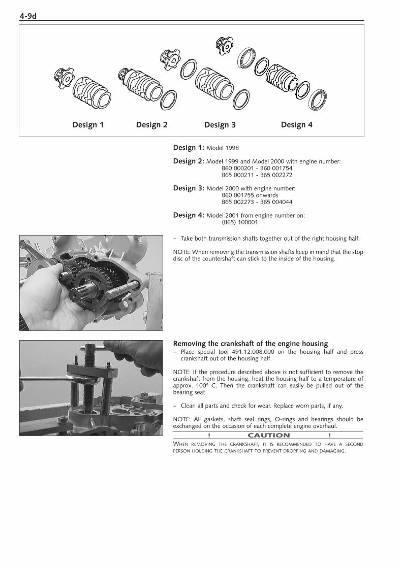
Design 1: Model 1998
Design 2: Model 1999 and Model 2000 with engine number:B60 000201 - B60 001754B65 000211 - B65 002272
Design 3: Model 2000 with engine number:B60 001755 onwardsB65 002273 - B65 004044
Design 4: Model 2001 from engine number on:(B65) 100001
– Take both transmission shafts together out of the right housing half.
NOTE: When removing the transmission shafts keep in mind that the stopdisc of the countershaft can stick to the inside of the housing.
Removing the crankshaft of the engine housing– Place special tool 491.12.008.000 on the housing half and press
crankshaft out of the housing half.
NOTE: If the procedure described above is not sufficient to remove thecrankshaft from the housing, heat the housing half to a temperature ofapprox. 100° C. Then the crankshaft can easily be pulled out of the bearing seat.
– Clean all parts and check for wear. Replace worn parts, if any.
NOTE: All gaskets, shaft seal rings, O-rings and bearings should beexchanged on the occasion of each complete engine overhaul.
! CAUTION !WHEN REMOVING THE CRANKSHAFT, IT IS RECOMMENDED TO HAVE A SECONDPERSON HOLDING THE CRANKSHAFT TO PREVENT DROPPING AND DAMAGING.
Design 1 Design 2 Design 3 Design 4
SERVICING ON INDIVIDUAL COMPONENTS
WORKS ON THE LEFT HOUSING HALF . . . . . . . . . . . . . . . . . . . . . . . . . .5-2
WORKS ON THE RIGHT HOUSING HALF . . . . . . . . . . . . . . . . . . . . . . . .5-3
WORKS ON THE CLUTCH COVER . . . . . . . . . . . . . . . . . . . . . . . . . . . . .5-4
MEASURING THE CRANKSHAFT . . . . . . . . . . . . . . . . . . . . . . . . . . . . . . .5-4
DISMANTLING AND CHECKING THE WATER PUMP . . . . . . . . . . . . . . . .5-5
CHECKING THE PISTON . . . . . . . . . . . . . . . . . . . . . . . . . . . . . . . . . . . . .5-6
PISTON RING END GAP . . . . . . . . . . . . . . . . . . . . . . . . . . . . . . . . . . . . .5-6
MEASURING PISTON AND CYLINDER, PISTON FITTING CLEARANCE . . .5-6
REED VALVE HOUSING, INTAKE FLANGE . . . . . . . . . . . . . . . . . . . . . . . . .5-7
DISASSEMBLING THE SHIFTING SHAFT . . . . . . . . . . . . . . . . . . . . . . . . . .5-8
SHIFTING MECHANISM - CHECKING PARTS FOR WEAR . . . . . . . . . . . . .5-8
PREASSEMBLING THE SHIFTING SHAFT . . . . . . . . . . . . . . . . . . . . . . . . . .5-8
CLUTCH - CHECKING PARTS FOR WEAR . . . . . . . . . . . . . . . . . . . . . . . .5-9
PREASSEMBLING THE DISC PACKAGE . . . . . . . . . . . . . . . . . . . . . . . . . . .5-9
PREASSEMBLE AND ASSEMBLE THE CLUTCH RELEASE . . . . . . . . . . . . .5-10
PREASSEMBLING THE KICKSTARTER SHAFT . . . . . . . . . . . . . . . . . . . . .5-10
TRANSMISSION - CHECKING PARTS FOR WEAR . . . . . . . . . . . . . . . . . .5-11
ASSEMBLING THE MAIN SHAFT . . . . . . . . . . . . . . . . . . . . . . . . . . . . . .5-11
ASSEMBLING THE COUNTER SHAFT . . . . . . . . . . . . . . . . . . . . . . . . . . .5-11
INDEX
5R
epai
r m
anua
l K
TM 6
0 SX
+ 6
5 SX
A
rt.-
No.
32
1066
-E
5-1d
IMPORTANT NOTE REGARDS WORKING ON ENGINE HOUSINGRead through the following section before commencing work. Then determine the assembly sequence so thatthe engine housing halves only need to be heated up once before replacing the bearings.
Having first removed the dowels, in order to expel the bearings or remove them with light mallet blows, thehousing halves must be placed on a suitably large plane surface, supporting the whole of the sealing surfacewithout damaging it. A wooden panel is best used as a base.
Bearings or shaft seal rings should not be hammered into their seats. If no suitable press is available, use a suitable mandrel and hammer them in with great care. Cold bearings will practically drop into their seats at anengine housing temperature of approx. 150° C.
After cooling, should the bearings fail to lock in the bore, they are bound to rotate after warming. In that eventthe housing must be replaced.

5-2dR
epai
r m
anua
l K
TM 6
0 SX
+ 6
5 SX
A
rt.-
No.
32
1066
-E
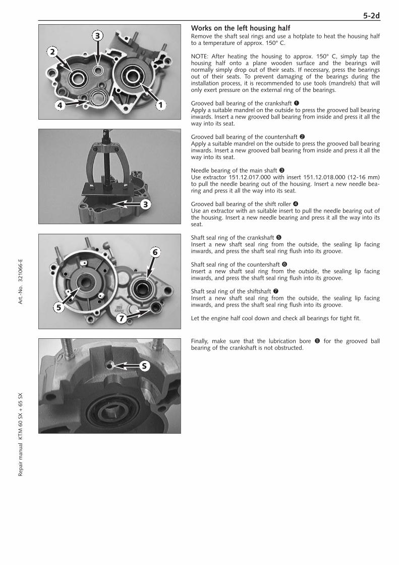
Works on the left housing halfRemove the shaft seal rings and use a hotplate to heat the housing halfto a temperature of approx. 150° C.
NOTE: After heating the housing to approx. 150° C, simply tap the housing half onto a plane wooden surface and the bearings will normally simply drop out of their seats. If necessary, press the bearingsout of their seats. To prevent damaging of the bearings during the installation process, it is recommended to use tools (mandrels) that willonly exert pressure on the external ring of the bearings.
Grooved ball bearing of the crankshaft 1Apply a suitable mandrel on the outside to press the grooved ball bearinginwards. Insert a new grooved ball bearing from inside and press it all theway into its seat.
Grooved ball bearing of the countershaft 2Apply a suitable mandrel on the outside to press the grooved ball bearinginwards. Insert a new grooved ball bearing from inside and press it all theway into its seat.
Needle bearing of the main shaft 3Use extractor 151.12.017.000 with insert 151.12.018.000 (12-16 mm)to pull the needle bearing out of the housing. Insert a new needle bea-ring and press it all the way into its seat.
Grooved ball bearing of the shift roller 4Use an extractor with an suitable insert to pull the needle bearing out ofthe housing. Insert a new needle bearing and press it all the way into itsseat.
Shaft seal ring of the crankshaft 5Insert a new shaft seal ring from the outside, the sealing lip facinginwards, and press the shaft seal ring flush into its groove.
Shaft seal ring of the countershaft 6Insert a new shaft seal ring from the outside, the sealing lip facinginwards, and press the shaft seal ring flush into its groove.
Shaft seal ring of the shiftshaft 7Insert a new shaft seal ring from the outside, the sealing lip facinginwards, and press the shaft seal ring flush into its groove.
Let the engine half cool down and check all bearings for tight fit.
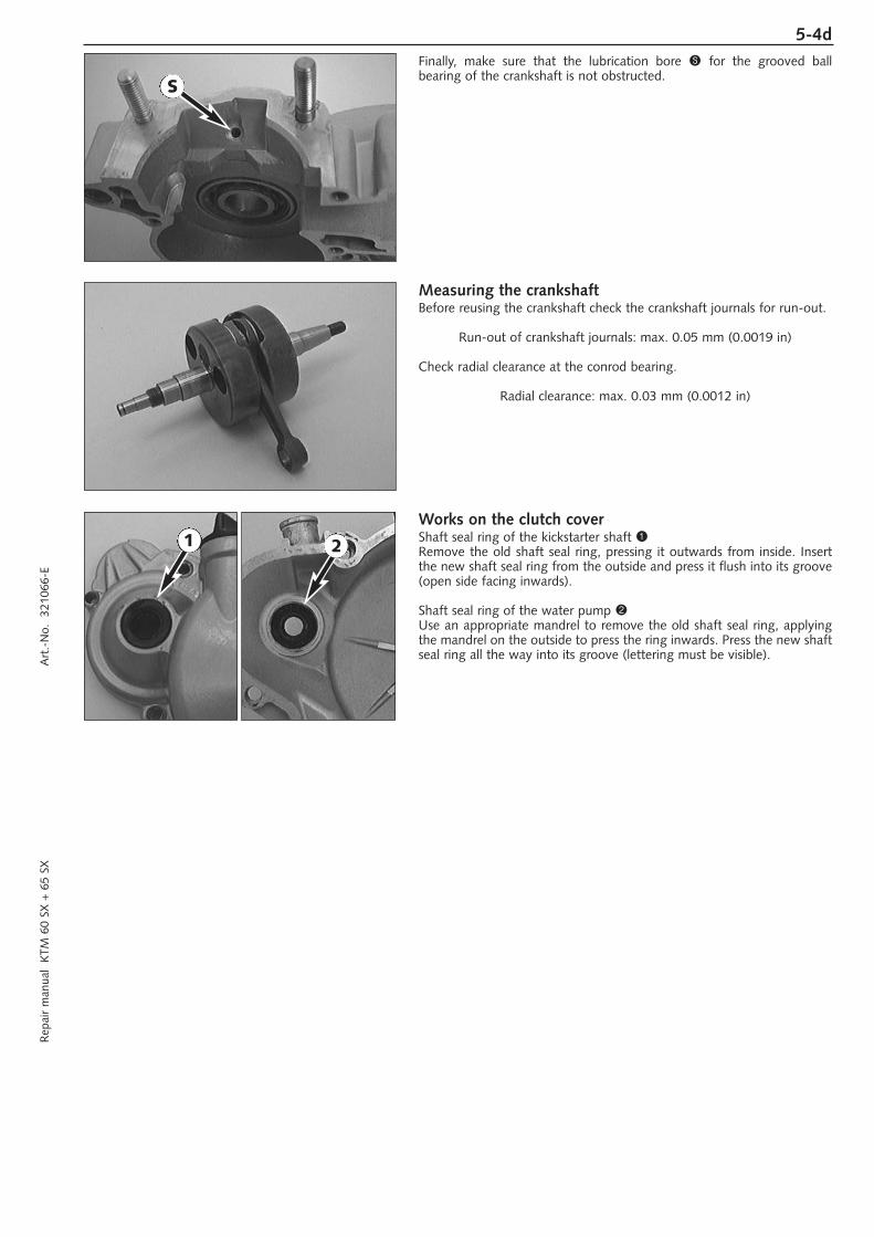
Finally, make sure that the lubrication bore S for the grooved ball bearing of the crankshaft is not obstructed.
1
2
3
5
3
S
6
4
7
5-3d
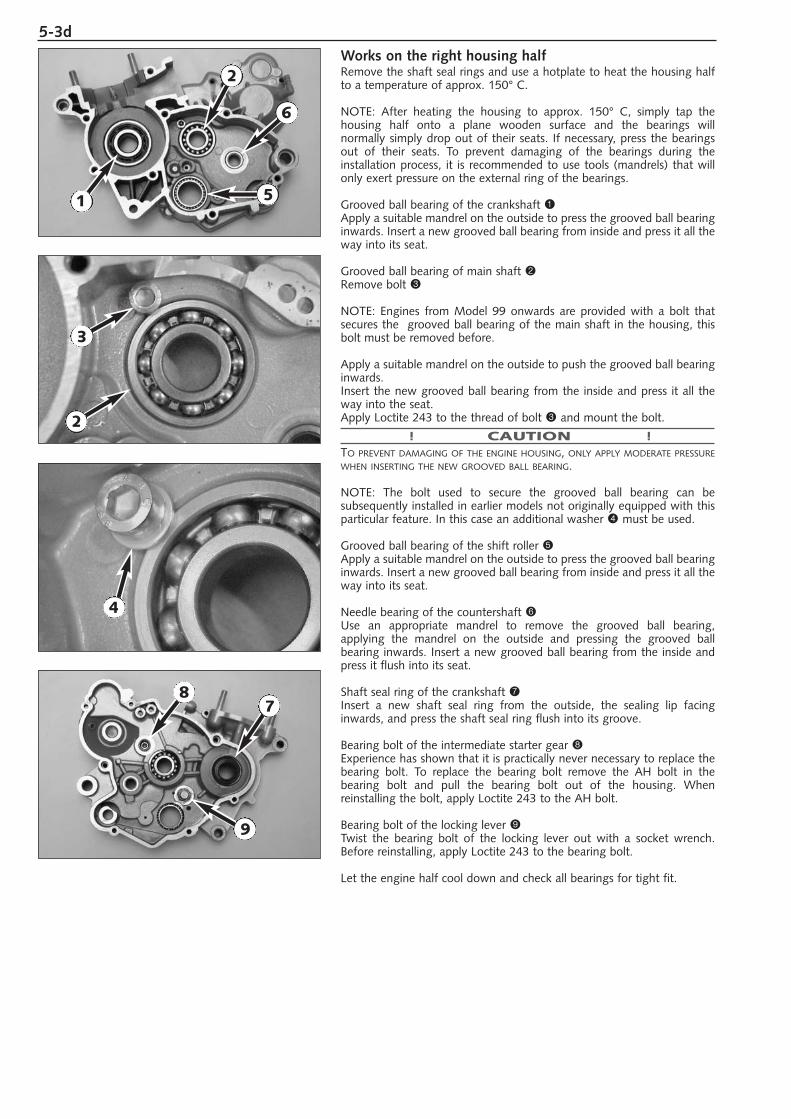
Works on the right housing halfRemove the shaft seal rings and use a hotplate to heat the housing halfto a temperature of approx. 150° C.
NOTE: After heating the housing to approx. 150° C, simply tap the housing half onto a plane wooden surface and the bearings will normally simply drop out of their seats. If necessary, press the bearingsout of their seats. To prevent damaging of the bearings during the installation process, it is recommended to use tools (mandrels) that willonly exert pressure on the external ring of the bearings.
Grooved ball bearing of the crankshaft 1Apply a suitable mandrel on the outside to press the grooved ball bearinginwards. Insert a new grooved ball bearing from inside and press it all theway into its seat.
Grooved ball bearing of main shaft 2Remove bolt 3
NOTE: Engines from Model 99 onwards are provided with a bolt thatsecures the grooved ball bearing of the main shaft in the housing, thisbolt must be removed before.
Apply a suitable mandrel on the outside to push the grooved ball bearinginwards.Insert the new grooved ball bearing from the inside and press it all theway into the seat.Apply Loctite 243 to the thread of bolt 3 and mount the bolt.
! CAUTION !TO PREVENT DAMAGING OF THE ENGINE HOUSING, ONLY APPLY MODERATE PRESSUREWHEN INSERTING THE NEW GROOVED BALL BEARING.
NOTE: The bolt used to secure the grooved ball bearing can be subsequently installed in earlier models not originally equipped with thisparticular feature. In this case an additional washer 4 must be used.
Grooved ball bearing of the shift roller 5Apply a suitable mandrel on the outside to press the grooved ball bearinginwards. Insert a new grooved ball bearing from inside and press it all theway into its seat.
Needle bearing of the countershaft 6Use an appropriate mandrel to remove the grooved ball bearing, applying the mandrel on the outside and pressing the grooved ball bearing inwards. Insert a new grooved ball bearing from the inside andpress it flush into its seat.
Shaft seal ring of the crankshaft 7Insert a new shaft seal ring from the outside, the sealing lip facinginwards, and press the shaft seal ring flush into its groove.
Bearing bolt of the intermediate starter gear 8Experience has shown that it is practically never necessary to replace thebearing bolt. To replace the bearing bolt remove the AH bolt in the bearing bolt and pull the bearing bolt out of the housing. When reinstalling the bolt, apply Loctite 243 to the AH bolt.
Bearing bolt of the locking lever 9Twist the bearing bolt of the locking lever out with a socket wrench.Before reinstalling, apply Loctite 243 to the bearing bolt.
Let the engine half cool down and check all bearings for tight fit.
2
1
2
3
4
5
78
6
9
5-4dR
epai
r m
anua
l K
TM 6
0 SX
+ 6
5 SX
A
rt.-
No.
32
1066
-E
Finally, make sure that the lubrication bore S for the grooved ball bearing of the crankshaft is not obstructed.
Measuring the crankshaftBefore reusing the crankshaft check the crankshaft journals for run-out.
Run-out of crankshaft journals: max. 0.05 mm (0.0019 in)
Check radial clearance at the conrod bearing.
Radial clearance: max. 0.03 mm (0.0012 in)
Works on the clutch coverShaft seal ring of the kickstarter shaft 1Remove the old shaft seal ring, pressing it outwards from inside. Insertthe new shaft seal ring from the outside and press it flush into its groove(open side facing inwards).
Shaft seal ring of the water pump 2Use an appropriate mandrel to remove the old shaft seal ring, applyingthe mandrel on the outside to press the ring inwards. Press the new shaftseal ring all the way into its groove (lettering must be visible).
S
1 2
5-5d
1
2
3
45
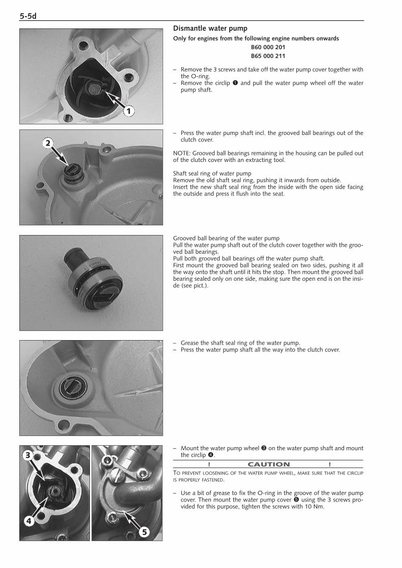
Dismantle water pumpOnly for engines from the following engine numbers onwards
B60 000 201B65 000 211
– Remove the 3 screws and take off the water pump cover together withthe O-ring.
– Remove the circlip 1 and pull the water pump wheel off the waterpump shaft.
– Press the water pump shaft incl. the grooved ball bearings out of theclutch cover.
NOTE: Grooved ball bearings remaining in the housing can be pulled outof the clutch cover with an extracting tool.
Shaft seal ring of water pumpRemove the old shaft seal ring, pushing it inwards from outside.Insert the new shaft seal ring from the inside with the open side facingthe outside and press it flush into the seat.
Grooved ball bearing of the water pumpPull the water pump shaft out of the clutch cover together with the groo-ved ball bearings.Pull both grooved ball bearings off the water pump shaft.First mount the grooved ball bearing sealed on two sides, pushing it allthe way onto the shaft until it hits the stop. Then mount the grooved ballbearing sealed only on one side, making sure the open end is on the insi-de (see pict.).
– Grease the shaft seal ring of the water pump.– Press the water pump shaft all the way into the clutch cover.
– Mount the water pump wheel 3 on the water pump shaft and mountthe circlip 4.
! CAUTION !TO PREVENT LOOSENING OF THE WATER PUMP WHEEL, MAKE SURE THAT THE CIRCLIPIS PROPERLY FASTENED.
– Use a bit of grease to fix the O-ring in the groove of the water pumpcover. Then mount the water pump cover 5 using the 3 screws pro-vided for this purpose, tighten the screws with 10 Nm.
5-6dR
epai
r m
anua
l K
TM 6
0 SX
+ 6
5 SX
A
rt.-
No.
32
1066
-E
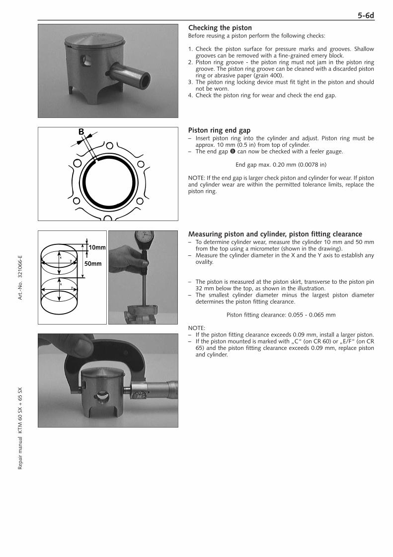
Checking the pistonBefore reusing a piston perform the following checks:
1. Check the piston surface for pressure marks and grooves. Shallowgrooves can be removed with a fine-grained emery block.
2. Piston ring groove - the piston ring must not jam in the piston ringgroove. The piston ring groove can be cleaned with a discarded pistonring or abrasive paper (grain 400).
3. The piston ring locking device must fit tight in the piston and shouldnot be worn.
4. Check the piston ring for wear and check the end gap.
Piston ring end gap– Insert piston ring into the cylinder and adjust. Piston ring must be
approx. 10 mm (0.5 in) from top of cylinder. – The end gap B can now be checked with a feeler gauge.
End gap max. 0.20 mm (0.0078 in)
NOTE: If the end gap is larger check piston and cylinder for wear. If pistonand cylinder wear are within the permitted tolerance limits, replace thepiston ring.
Measuring piston and cylinder, piston fitting clearance– To determine cylinder wear, measure the cylinder 10 mm and 50 mm
from the top using a micrometer (shown in the drawing).– Measure the cylinder diameter in the X and the Y axis to establish any
ovality.
– The piston is measured at the piston skirt, transverse to the piston pin32 mm below the top, as shown in the illustration.
– The smallest cylinder diameter minus the largest piston diameter determines the piston fitting clearance.
Piston fitting clearance: 0.055 - 0.065 mm
NOTE:– If the piston fitting clearance exceeds 0.09 mm, install a larger piston.– If the piston mounted is marked with „C“ (on CR 60) or „E/F“ (on CR
65) and the piston fitting clearance exceeds 0.09 mm, replace pistonand cylinder.
xy
10mm
xy
50mm
5-7d
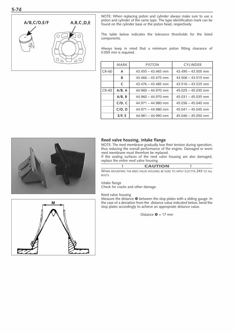
Reed valve housing, intake flangeNOTE: The reed membrane gradually lose their tension during operation,thus reducing the overall performance of the engine. Damaged or wornreed membrane must therefore be replaced.If the sealing surfaces of the reed valve housing are also damaged, replace the entire reed valve housing.
! CAUTION !WHEN MOUNTING THE REED VALVE HOUSING BE SURE TO APPLY LOCTITE 243 TO ALLBOLTS.
Intake flangeCheck for cracks and other damage.
Reed valve housingMeasure the distance M between the stop plates with a sliding gauge. Inthe case of a deviation from the distance value indicated below, bend thestop plates accordingly to achieve an appropriate distance value.
Distance M = 17 mm
NOTE: When replacing piston and cylinder always make sure to use apiston and cylinder of the same type. The type identification mark can befound on the cylinder base or the piston head, respectively.
The table below indicates the tolerance thresholds for the listed components.
Always keep in mind that a minimum piston fitting clearance of 0.055 mm is required.
M
,D,E
MARK PISTON CYLINDER
CR-60 A 43.455 – 43.465 mm 43.495 – 43.505 mm
B 43.466 – 43.475 mm 43.506 – 43.515 mm
C 43.476 – 43.485 mm 43.516 – 43.525 mm
CR-65 A/B, A 44.960 – 44.970 mm 45.025 – 45.030 mm
A/B, B 44.960 – 44.970 mm 45.031 – 45.035 mm
C/D, C 44.971 – 44.980 mm 45.036 – 45.040 mm
C/D, D 44.971 – 44.980 mm 45.041 – 45.045 mm
E/F, E 44.981 – 44.990 mm 45.046 – 45.050 mm
5-8dR
epai
r m
anua
l K
TM 6
0 SX
+ 6
5 SX
A
rt.-
No.
32
1066
-E
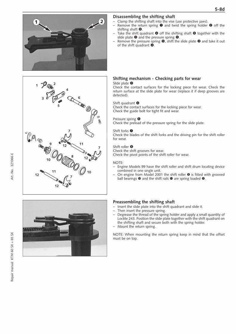
Disassembling the shifting shaft– Clamp the shifting shaft into the vise (use protective jaws).– Remove the return spring 1 and twist the spring holder 2 off the
shifting shaft 6.– Take the shift quadrant 4 off the shifting shaft 6 together with the
slide plate 3 and the pressure spring 5.– Remove the pressure spring 5, shift the slide plate 3 and take it out
of the shift quadrant 4.
Shifting mechanism - Checking parts for wearSlide plate 3Check the contact surfaces for the locking piece for wear. Check thereturn surface at the slide plate for wear (replace it if deep grooves aredetected).
Shift quadrant 4Check the contact surfaces for the locking piece for wear.Check the guide bolt for tight fit and wear.
Pressure spring 5Check the preload of the pressure spring for the slide plate.
Shift forks 7Check the blades of the shift forks and the driving pin for the shift rollerfor wear.
Shift roller 8Check the shift grooves for wear.Check the pivot points of the shift roller for wear.
NOTE:– Engine Models 99 have the shift roller and shift drum locating device
combined in one single unit. – On engine from Model 2001 the shift roller 8 is fitted with grooved
ball bearings bk and the shift rails bl are spring loaded bm.
Preassembling the shifting shaft– Insert the slide plate into the shift quadrant and slide it.– Then insert the pressure spring.– Degrease the thread of the spring holder and apply a small quantity of
Loctite 243. Position the slide plate together with the shift quadrant onthe shifting shaft and secure both with the spring holder.
– Mount the return spring.
NOTE: When mounting the return spring keep in mind that the offsetmust be on top.
1 2
1 2
3
4
5
6
7
7
8
7
11
119
12
12
12
12
10
10
5-9d
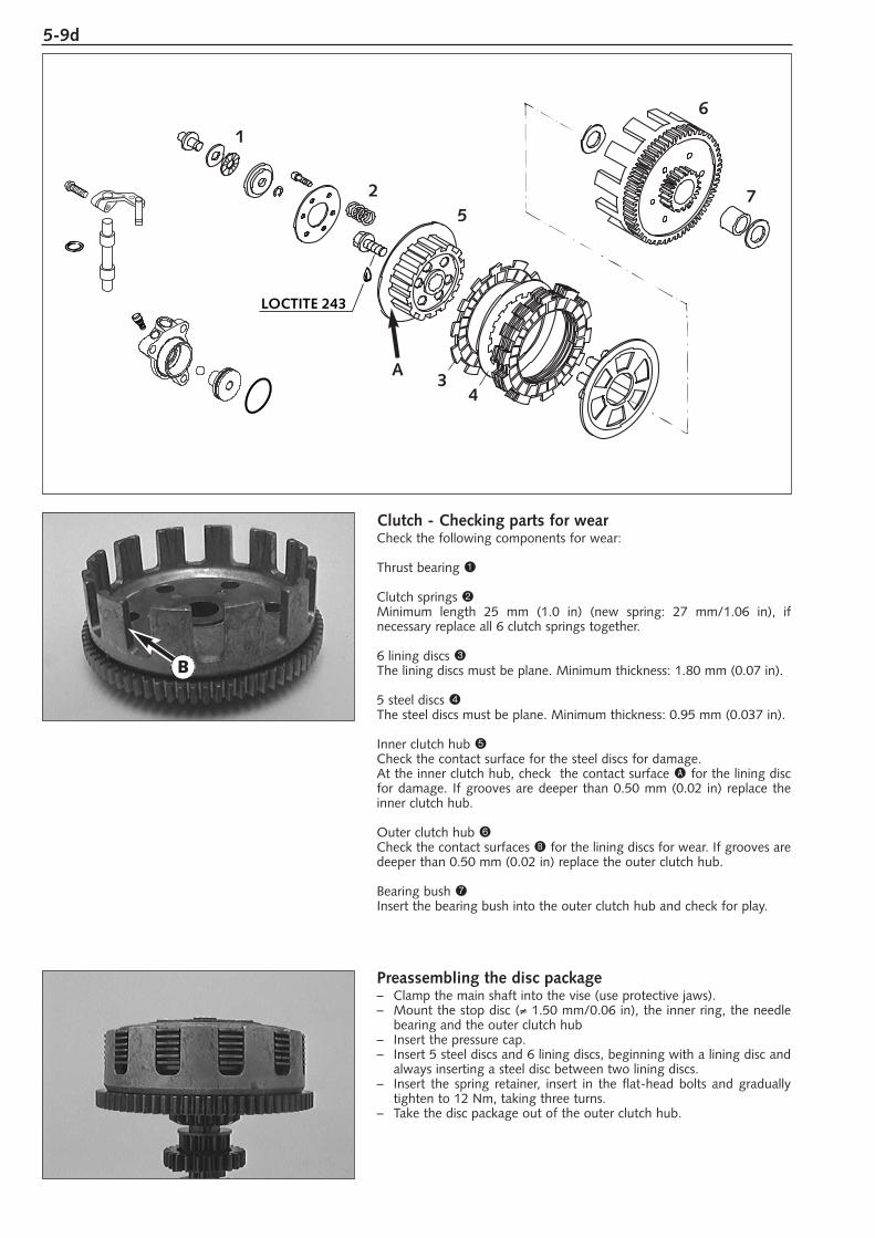
Clutch - Checking parts for wearCheck the following components for wear:
Thrust bearing 1
Clutch springs 2Minimum length 25 mm (1.0 in) (new spring: 27 mm/1.06 in), if necessary replace all 6 clutch springs together.
6 lining discs 3The lining discs must be plane. Minimum thickness: 1.80 mm (0.07 in).
5 steel discs 4The steel discs must be plane. Minimum thickness: 0.95 mm (0.037 in).
Inner clutch hub 5Check the contact surface for the steel discs for damage.At the inner clutch hub, check the contact surface A for the lining discfor damage. If grooves are deeper than 0.50 mm (0.02 in) replace theinner clutch hub.
Outer clutch hub 6Check the contact surfaces B for the lining discs for wear. If grooves aredeeper than 0.50 mm (0.02 in) replace the outer clutch hub.
Bearing bush 7Insert the bearing bush into the outer clutch hub and check for play.
Preassembling the disc package – Clamp the main shaft into the vise (use protective jaws).– Mount the stop disc (≠ 1.50 mm/0.06 in), the inner ring, the needle
bearing and the outer clutch hub– Insert the pressure cap. – Insert 5 steel discs and 6 lining discs, beginning with a lining disc and
always inserting a steel disc between two lining discs.– Insert the spring retainer, insert in the flat-head bolts and gradually
tighten to 12 Nm, taking three turns. – Take the disc package out of the outer clutch hub.
B
LOCTITE 243
1
2 75
6
A3
4
5-10dR
epai
r m
anua
l K
TM 6
0 SX
+ 6
5 SX
A
rt.-
No.
32
1066
-E
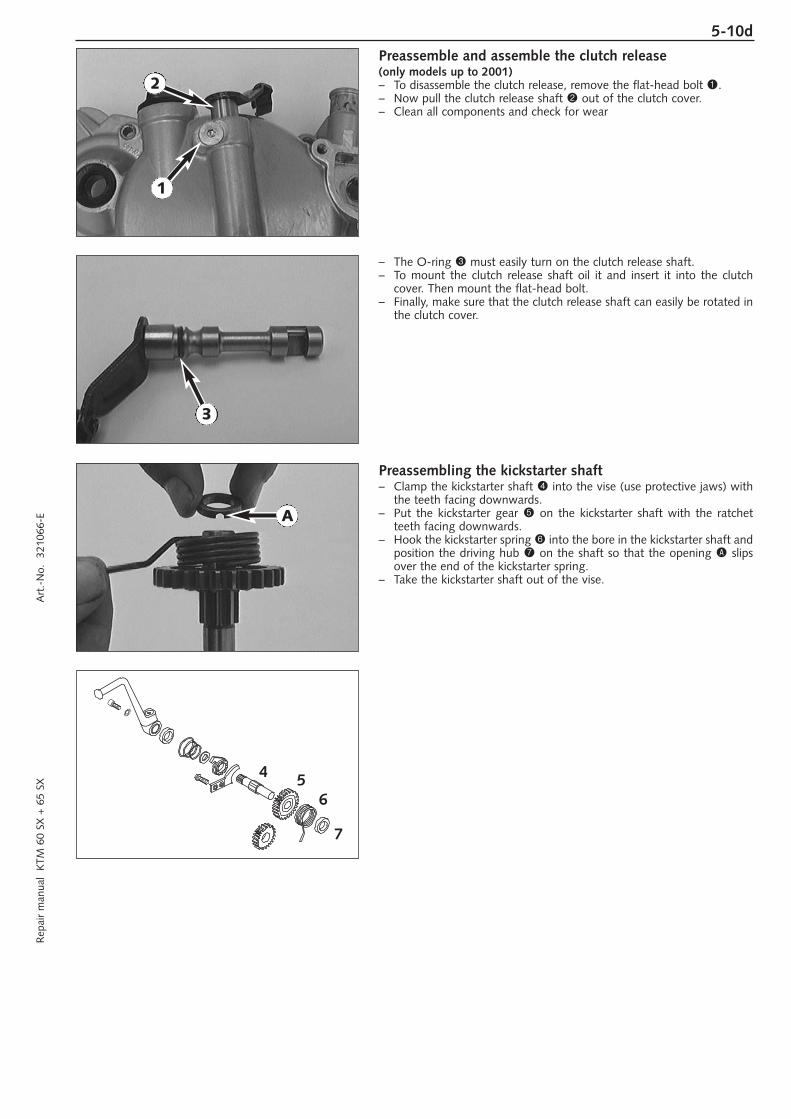
Preassemble and assemble the clutch release(only models up to 2001)– To disassemble the clutch release, remove the flat-head bolt 1.– Now pull the clutch release shaft 2 out of the clutch cover.– Clean all components and check for wear
– The O-ring 3 must easily turn on the clutch release shaft.– To mount the clutch release shaft oil it and insert it into the clutch
cover. Then mount the flat-head bolt.– Finally, make sure that the clutch release shaft can easily be rotated in
the clutch cover.
Preassembling the kickstarter shaft– Clamp the kickstarter shaft 4 into the vise (use protective jaws) with
the teeth facing downwards.– Put the kickstarter gear 5 on the kickstarter shaft with the ratchet
teeth facing downwards.– Hook the kickstarter spring 6 into the bore in the kickstarter shaft and
position the driving hub 7 on the shaft so that the opening A slipsover the end of the kickstarter spring.
– Take the kickstarter shaft out of the vise.
2
1
3
A
4 56
7
5-11d
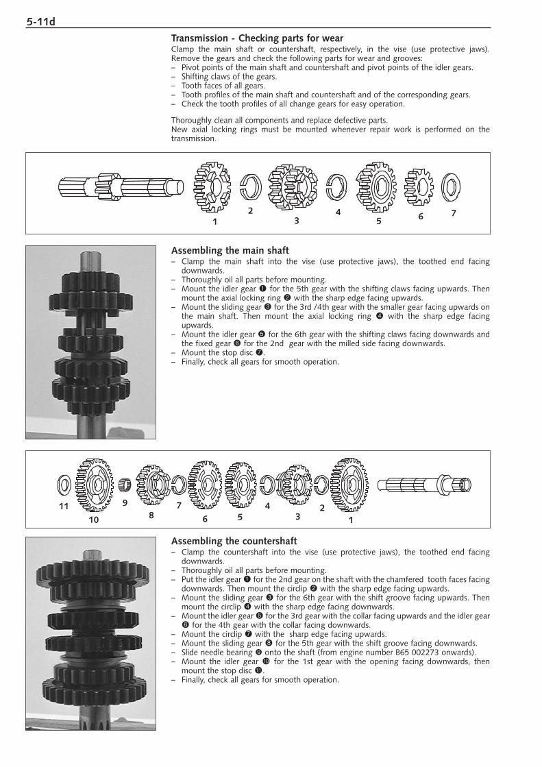
Transmission - Checking parts for wearClamp the main shaft or countershaft, respectively, in the vise (use protective jaws).Remove the gears and check the following parts for wear and grooves:– Pivot points of the main shaft and countershaft and pivot points of the idler gears.– Shifting claws of the gears.– Tooth faces of all gears.– Tooth profiles of the main shaft and countershaft and of the corresponding gears.– Check the tooth profiles of all change gears for easy operation.
Thoroughly clean all components and replace defective parts.New axial locking rings must be mounted whenever repair work is performed on the transmission.
Assembling the main shaft– Clamp the main shaft into the vise (use protective jaws), the toothed end facing
downwards.– Thoroughly oil all parts before mounting.– Mount the idler gear 1 for the 5th gear with the shifting claws facing upwards. Then
mount the axial locking ring 2 with the sharp edge facing upwards.– Mount the sliding gear 3 for the 3rd /4th gear with the smaller gear facing upwards on
the main shaft. Then mount the axial locking ring 4 with the sharp edge facingupwards.
– Mount the idler gear 5 for the 6th gear with the shifting claws facing downwards andthe fixed gear 6 for the 2nd gear with the milled side facing downwards.
– Mount the stop disc 7.– Finally, check all gears for smooth operation.
Assembling the countershaft– Clamp the countershaft into the vise (use protective jaws), the toothed end facing
downwards.– Thoroughly oil all parts before mounting.– Put the idler gear 1 for the 2nd gear on the shaft with the chamfered tooth faces facing
downwards. Then mount the circlip 2 with the sharp edge facing upwards.– Mount the sliding gear 3 for the 6th gear with the shift groove facing upwards. Then
mount the circlip 4 with the sharp edge facing downwards.– Mount the idler gear 5 for the 3rd gear with the collar facing upwards and the idler gear
6 for the 4th gear with the collar facing downwards.– Mount the circlip 7 with the sharp edge facing upwards.– Mount the sliding gear 8 for the 5th gear with the shift groove facing downwards.– Slide needle bearing 9 onto the shaft (from engine number B65 002273 onwards).– Mount the idler gear bk for the 1st gear with the opening facing downwards, then
mount the stop disc bl.– Finally, check all gears for smooth operation.
41
23 5 6 7
11
10
98 6 5
43
7 21
ASSEMBLING THE ENGINE
INSERTING THE CRANKSHAFT . . . . . . . . . . . . . . . . . . . . . . . . . . . . . . . . .6-2
MOUNT TRANSMISSION AND SHIFT MECHANISM . . . . . . . . . . . . . . . . .6-2
ASSEMBLING THE ENGINE HOUSING . . . . . . . . . . . . . . . . . . . . . . . . . . .6-3
MOUNT KICKSTARTER SHAFT . . . . . . . . . . . . . . . . . . . . . . . . . . . . . . . . .6-3
MOUNT SHIFT MECHANISM AND SHIFT SHAFT . . . . . . . . . . . . . . . . . . .6-3
ASSEMBLE CLUTCH . . . . . . . . . . . . . . . . . . . . . . . . . . . . . . . . . . . . . . . .6-4
MOUNT PRIMARY DRIVE . . . . . . . . . . . . . . . . . . . . . . . . . . . . . . . . . . . .6-5
MOUNT RATCHET GEAR, PRELOAD THE KICKSTARTER SHAFT . . . . . . . .6-5
MOUNT CLUTCH COVER . . . . . . . . . . . . . . . . . . . . . . . . . . . . . . . . . . . .6-5
MOUNT THE ENGINE SPROCKET . . . . . . . . . . . . . . . . . . . . . . . . . . . . . .6-6
MOUNT REED VALVE HOUSING AND INKTAKE FLANGE . . . . . . . . . . . . .6-6
MOUNT PISTON AND CYLINDER . . . . . . . . . . . . . . . . . . . . . . . . . . . . . .6-7
ADJUSTING DIMENSION „X“ . . . . . . . . . . . . . . . . . . . . . . . . . . . . . . . . .6-7
IGNITION, ADJUSTING THE IGNITION UP TO MODEL 2002 . . . . . . . . . .6-8
IGNITION, ADJUSTING THE IGNITION FROM MODEL 2003 . . . . . . . . . .6-9
MOUNT CYLINDER HEAD . . . . . . . . . . . . . . . . . . . . . . . . . . . . . . . . . . .6-10
MOUNT KICKSTARTER . . . . . . . . . . . . . . . . . . . . . . . . . . . . . . . . . . . . .6-10
MOUNT IGNITION COVER . . . . . . . . . . . . . . . . . . . . . . . . . . . . . . . . . .6-10
FILLING GEAR OIL . . . . . . . . . . . . . . . . . . . . . . . . . . . . . . . . . . . . . . . . .6-10
INDEX
6R
epai
r m
anua
l K
TM 6
0 SX
+ 6
5 SX
A
rt.-
No.
32
1066
-E
6-1d

6-2dR
epai
r m
anua
l K
TM 6
0 SX
+ 6
5 SX
A
rt.-
No.
32
1066
-E
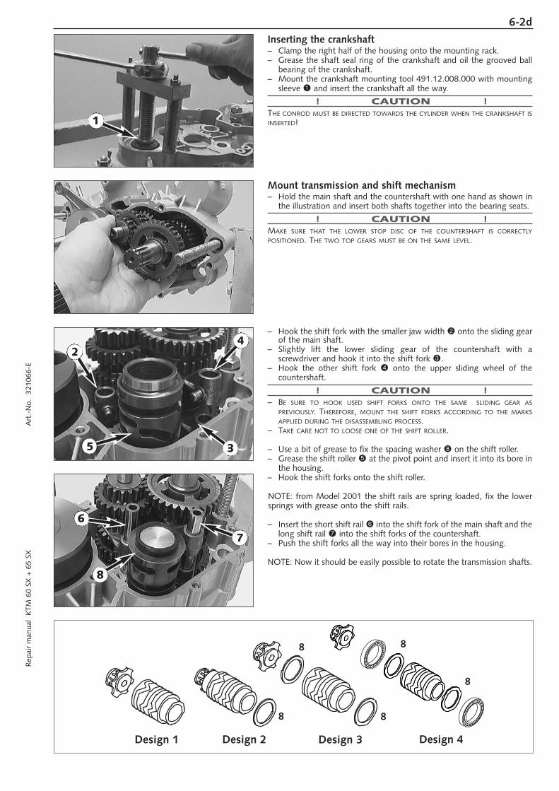
Inserting the crankshaft– Clamp the right half of the housing onto the mounting rack.– Grease the shaft seal ring of the crankshaft and oil the grooved ball
bearing of the crankshaft.– Mount the crankshaft mounting tool 491.12.008.000 with mounting
sleeve 1 and insert the crankshaft all the way.
! CAUTION !THE CONROD MUST BE DIRECTED TOWARDS THE CYLINDER WHEN THE CRANKSHAFT ISINSERTED!
Mount transmission and shift mechanism– Hold the main shaft and the countershaft with one hand as shown in
the illustration and insert both shafts together into the bearing seats.
! CAUTION !MAKE SURE THAT THE LOWER STOP DISC OF THE COUNTERSHAFT IS CORRECTLYPOSITIONED. THE TWO TOP GEARS MUST BE ON THE SAME LEVEL.
– Hook the shift fork with the smaller jaw width 2 onto the sliding gearof the main shaft.
– Slightly lift the lower sliding gear of the countershaft with a screwdriver and hook it into the shift fork 3.
– Hook the other shift fork 4 onto the upper sliding wheel of the countershaft.
! CAUTION !– BE SURE TO HOOK USED SHIFT FORKS ONTO THE SAME SLIDING GEAR AS
PREVIOUSLY. THEREFORE, MOUNT THE SHIFT FORKS ACCORDING TO THE MARKSAPPLIED DURING THE DISASSEMBLING PROCESS.
– TAKE CARE NOT TO LOOSE ONE OF THE SHIFT ROLLER.
– Use a bit of grease to fix the spacing washer 8 on the shift roller.– Grease the shift roller 5 at the pivot point and insert it into its bore in
the housing.– Hook the shift forks onto the shift roller.
NOTE: from Model 2001 the shift rails are spring loaded, fix the lowersprings with grease onto the shift rails.
– Insert the short shift rail 6 into the shift fork of the main shaft and thelong shift rail 7 into the shift forks of the countershaft.
– Push the shift forks all the way into their bores in the housing.
NOTE: Now it should be easily possible to rotate the transmission shafts.
7
1
6
24
5 3
8
Design 1 Design 2 Design 3 Design 4
8
8
8
8
8
6-3d
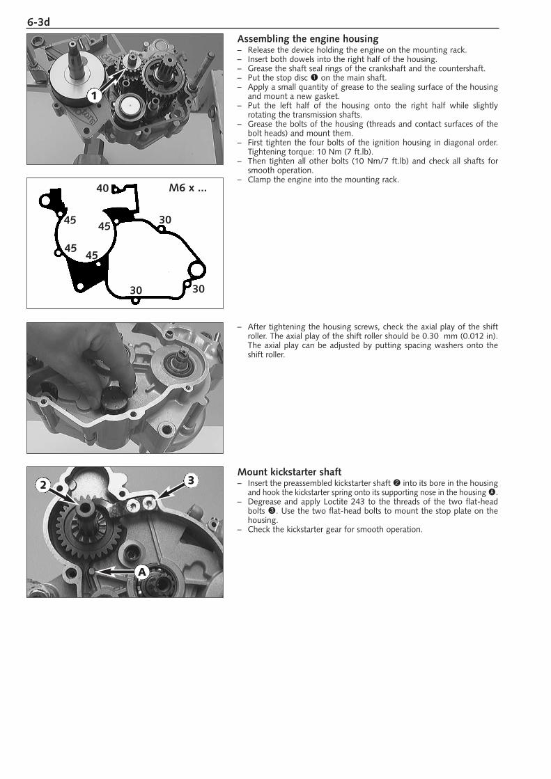
Assembling the engine housing– Release the device holding the engine on the mounting rack.– Insert both dowels into the right half of the housing.– Grease the shaft seal rings of the crankshaft and the countershaft.– Put the stop disc 1 on the main shaft.– Apply a small quantity of grease to the sealing surface of the housing
and mount a new gasket.– Put the left half of the housing onto the right half while slightly
rotating the transmission shafts.– Grease the bolts of the housing (threads and contact surfaces of the
bolt heads) and mount them.– First tighten the four bolts of the ignition housing in diagonal order.
Tightening torque: 10 Nm (7 ft.lb).– Then tighten all other bolts (10 Nm/7 ft.lb) and check all shafts for
smooth operation.– Clamp the engine into the mounting rack.
– After tightening the housing screws, check the axial play of the shiftroller. The axial play of the shift roller should be 0.30 mm (0.012 in).The axial play can be adjusted by putting spacing washers onto theshift roller.
Mount kickstarter shaft– Insert the preassembled kickstarter shaft 2 into its bore in the housing
and hook the kickstarter spring onto its supporting nose in the housing A.– Degrease and apply Loctite 243 to the threads of the two flat-head
bolts 3. Use the two flat-head bolts to mount the stop plate on thehousing.
– Check the kickstarter gear for smooth operation.
A
M6 x ...
30
3030
40
45
4545
45
2
1
3
6-4dR
epai
r m
anua
l K
TM 6
0 SX
+ 6
5 SX
A
rt.-
No.
32
1066
-E
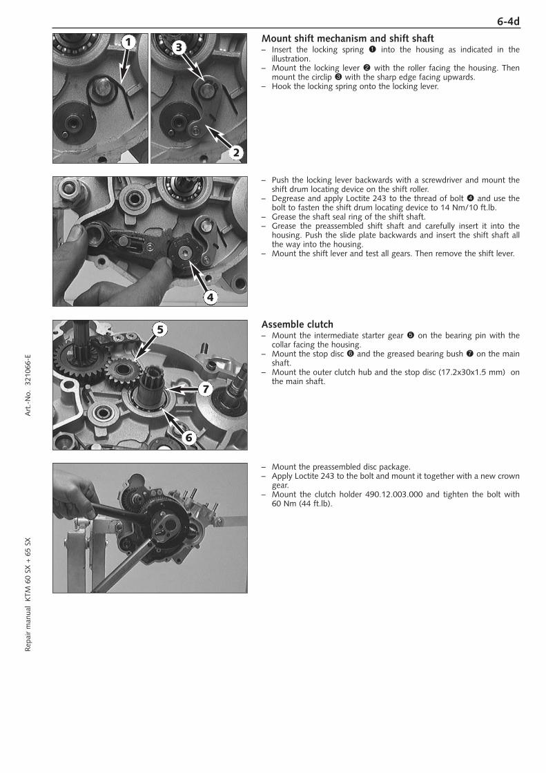
Mount shift mechanism and shift shaft– Insert the locking spring 1 into the housing as indicated in the
illustration.– Mount the locking lever 2 with the roller facing the housing. Then
mount the circlip 3 with the sharp edge facing upwards.– Hook the locking spring onto the locking lever.
– Push the locking lever backwards with a screwdriver and mount theshift drum locating device on the shift roller.
– Degrease and apply Loctite 243 to the thread of bolt 4 and use thebolt to fasten the shift drum locating device to 14 Nm/10 ft.lb.
– Grease the shaft seal ring of the shift shaft.– Grease the preassembled shift shaft and carefully insert it into the
housing. Push the slide plate backwards and insert the shift shaft allthe way into the housing.
– Mount the shift lever and test all gears. Then remove the shift lever.
Assemble clutch– Mount the intermediate starter gear 5 on the bearing pin with the
collar facing the housing. – Mount the stop disc 6 and the greased bearing bush 7 on the main
shaft.– Mount the outer clutch hub and the stop disc (17.2x30x1.5 mm) on
the main shaft.
– Mount the preassembled disc package.– Apply Loctite 243 to the bolt and mount it together with a new crown
gear.– Mount the clutch holder 490.12.003.000 and tighten the bolt with
60 Nm (44 ft.lb).
1
2
3
4
5
6
7
6-5d
1
7
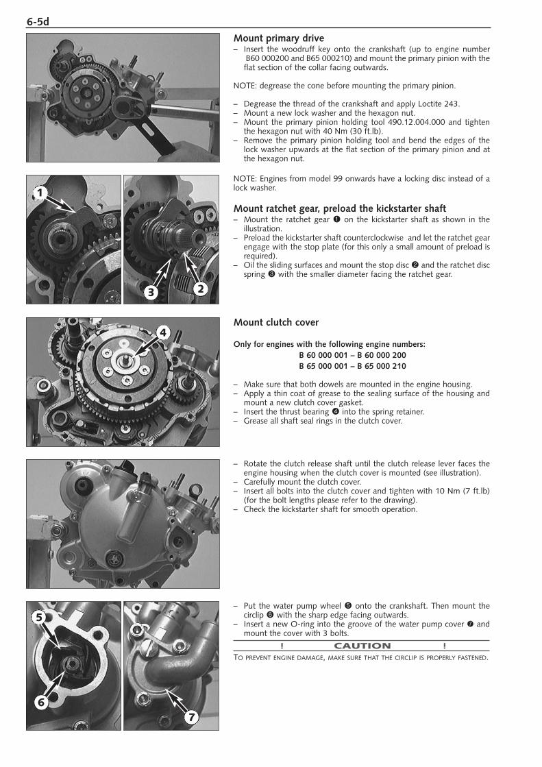
Mount primary drive– Insert the woodruff key onto the crankshaft (up to engine number
B60 000200 and B65 000210) and mount the primary pinion with theflat section of the collar facing outwards.
NOTE: degrease the cone before mounting the primary pinion.
– Degrease the thread of the crankshaft and apply Loctite 243.– Mount a new lock washer and the hexagon nut.– Mount the primary pinion holding tool 490.12.004.000 and tighten
the hexagon nut with 40 Nm (30 ft.lb).– Remove the primary pinion holding tool and bend the edges of the
lock washer upwards at the flat section of the primary pinion and atthe hexagon nut.
NOTE: Engines from model 99 onwards have a locking disc instead of alock washer.
Mount ratchet gear, preload the kickstarter shaft– Mount the ratchet gear 1 on the kickstarter shaft as shown in the
illustration.– Preload the kickstarter shaft counterclockwise and let the ratchet gear
engage with the stop plate (for this only a small amount of preload isrequired).
– Oil the sliding surfaces and mount the stop disc 2 and the ratchet discspring 3 with the smaller diameter facing the ratchet gear.
Mount clutch cover
Only for engines with the following engine numbers:B 60 000 001 – B 60 000 200B 65 000 001 – B 65 000 210
– Make sure that both dowels are mounted in the engine housing.– Apply a thin coat of grease to the sealing surface of the housing and
mount a new clutch cover gasket.– Insert the thrust bearing 4 into the spring retainer.– Grease all shaft seal rings in the clutch cover.
– Rotate the clutch release shaft until the clutch release lever faces theengine housing when the clutch cover is mounted (see illustration).
– Carefully mount the clutch cover.– Insert all bolts into the clutch cover and tighten with 10 Nm (7 ft.lb)
(for the bolt lengths please refer to the drawing).– Check the kickstarter shaft for smooth operation.
– Put the water pump wheel 5 onto the crankshaft. Then mount thecirclip 6 with the sharp edge facing outwards.
– Insert a new O-ring into the groove of the water pump cover 7 andmount the cover with 3 bolts.
! CAUTION !TO PREVENT ENGINE DAMAGE, MAKE SURE THAT THE CIRCLIP IS PROPERLY FASTENED.
3 2
4
5
6
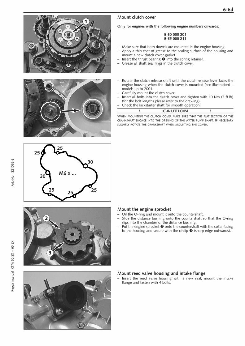
Mount clutch cover
Only for engines with the following engine numbers onwards:
B 60 000 201B 65 000 211
– Make sure that both dowels are mounted in the engine housing.– Apply a thin coat of grease to the sealing surface of the housing and
mount a new clutch cover gasket.– Insert the thrust bearing 1 into the spring retainer.– Grease all shaft seal rings in the clutch cover.
– Rotate the clutch release shaft until the clutch release lever faces theengine housing when the clutch cover is mounted (see illustration) –models up to 2001.
– Carefully mount the clutch cover.– Insert all bolts into the clutch cover and tighten with 10 Nm (7 ft.lb)
(for the bolt lengths please refer to the drawing).– Check the kickstarter shaft for smooth operation.
! CAUTION !WHEN MOUNTING THE CLUTCH COVER MAKE SURE THAT THE FLAT SECTION OF THECRANKSHAFT ENGAGE INTO THE OPENING OF THE WATER PUMP SHAFT. IF NECESSARYSLIGHTLY ROTATE THE CRANKSHAFT WHEN MOUNTING THE COVER.
Mount the engine sprocket– Oil the O-ring and mount it onto the countershaft.– Slide the distance bushing onto the countershaft so that the O-ring
slips into the chamber of the distance bushing.– Put the engine sprocket 2 onto the countershaft with the collar facing
to the housing and secure with the circlip 3 (sharp edge outwards).
Mount reed valve housing and intake flange– Insert the reed valve housing with a new seal, mount the intake
flange and fasten with 4 bolts.
6-6dR
epai
r m
anua
l K
TM 6
0 SX
+ 6
5 SX
A
rt.-
No.
32
1066
-E
M6 x ...
2525
30
252525
30
2
1
3
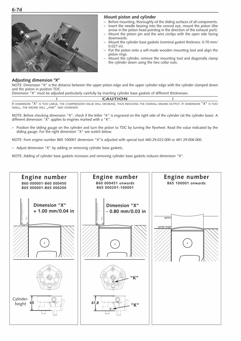
Mount piston and cylinder– Before mounting, thoroughly oil the sliding surfaces of all components.– Insert the needle bearing into the conrod eye, mount the piston (the
arrow in the piston head pointing in the direction of the exhaust port).– Mount the piston pin and the wire circlips with the open side facing
downwards.– Mount the cylinder base gaskets (nominal gasket thickness: 0.70 mm/
0.027 in).– Put the piston onto a self-made wooden mounting tool and align the
piston rings.– Mount the cylinder, remove the mounting tool and diagonally clamp
the cylinder down using the two collar nuts.
6-7d
Adjusting dimension "X" NOTE: Dimension "X" is the distance between the upper piston edge and the upper cylinder edge with the cylinder clamped downand the piston in position TDC. Dimension "X" must be adjusted particularly carefully by inserting cylinder base gaskets of different thicknesses.
! CAUTION !IF DIMENSION "X" IS TOO LARGE, THE COMPRESSION VALUE WILL DECREASE, THUS REDUCING THE OVERALL ENGINE OUTPUT. IF DIMENSION "X" IS TOOSMALL, THE ENGINE WILL „PINK“ AND OVERHEAT.
NOTE: Before checking dimension "X", check if the letter "K" is engraved on the right side of the cylinder (at the cylinder base). Adifferent dimension "X" applies to engines marked with a "K".
– Position the sliding gauge on the cylinder and turn the piston to TDC by turning the flywheel. Read the value indicated by thesliding gauge. For the right dimension "X" see scetch below.
NOTE: from engine number B65 100001 dimension "X"is adjusted with special tool 460.29.022.000 or 461.29.006.000.
– Adjust dimension "X" by adding or removing cylinder base gaskets.
NOTE: Adding of cylinder base gaskets increases and removing cylinder base gaskets reduces dimension "X".
60
mm
ST
AIN
LES
S
HA
RD
EN
EN
D
Dimension “X“+ 1.00 mm/0.04 in
K
K
61,8
mm
ST
AIN
LES
S
HA
RD
EN
EN
D
Dimension “X“- 0.80 mm/0.03 in
“K“
“K“
Engine numberB60 000451 onwardsB65 000201-100001
Engine numberB60 000001-B60 000450B65 000001-B65 000200
Cylinder-height
Engine numberB65 100001 onwards
ignition
cylinder height
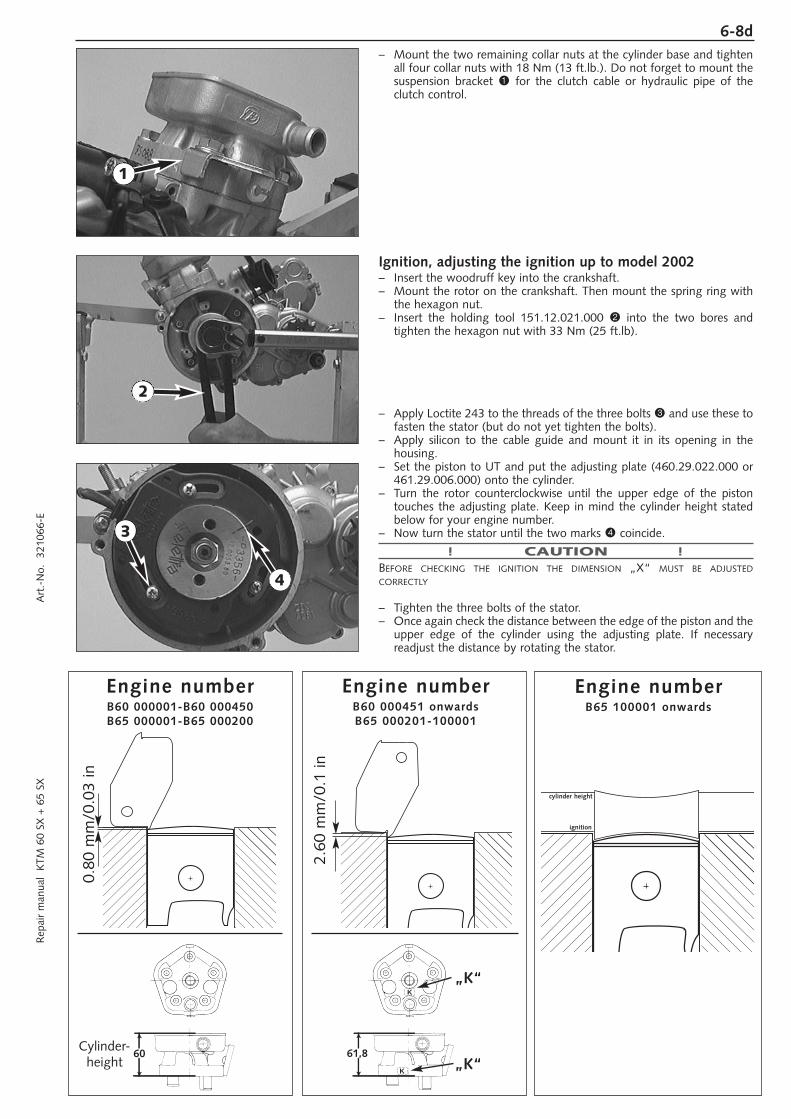
– Mount the two remaining collar nuts at the cylinder base and tightenall four collar nuts with 18 Nm (13 ft.lb.). Do not forget to mount thesuspension bracket 1 for the clutch cable or hydraulic pipe of theclutch control.
Ignition, adjusting the ignition up to model 2002– Insert the woodruff key into the crankshaft.– Mount the rotor on the crankshaft. Then mount the spring ring with
the hexagon nut.– Insert the holding tool 151.12.021.000 2 into the two bores and
tighten the hexagon nut with 33 Nm (25 ft.lb).
– Apply Loctite 243 to the threads of the three bolts 3 and use these tofasten the stator (but do not yet tighten the bolts).
– Apply silicon to the cable guide and mount it in its opening in the housing.
– Set the piston to UT and put the adjusting plate (460.29.022.000 or461.29.006.000) onto the cylinder.
– Turn the rotor counterclockwise until the upper edge of the piston touches the adjusting plate. Keep in mind the cylinder height statedbelow for your engine number.
– Now turn the stator until the two marks 4 coincide.
! CAUTION !BEFORE CHECKING THE IGNITION THE DIMENSION „X“ MUST BE ADJUSTEDCORRECTLY
– Tighten the three bolts of the stator.– Once again check the distance between the edge of the piston and the
upper edge of the cylinder using the adjusting plate. If necessary readjust the distance by rotating the stator.
6-8dR
epai
r m
anua
l K
TM 6
0 SX
+ 6
5 SX
A
rt.-
No.
32
1066
-E
1
Engine numberB60 000001-B60 000450B65 000001-B65 000200
Engine numberB60 000451 onwardsB65 000201-100001
60
K
K
61,8
„K“
„K“
0.80
mm
/0.0
3 in
2.60
mm
/0.1
in
Cylinder-height
Engine numberB65 100001 onwards
cylinder height
ignition
3
2
4
6-9d
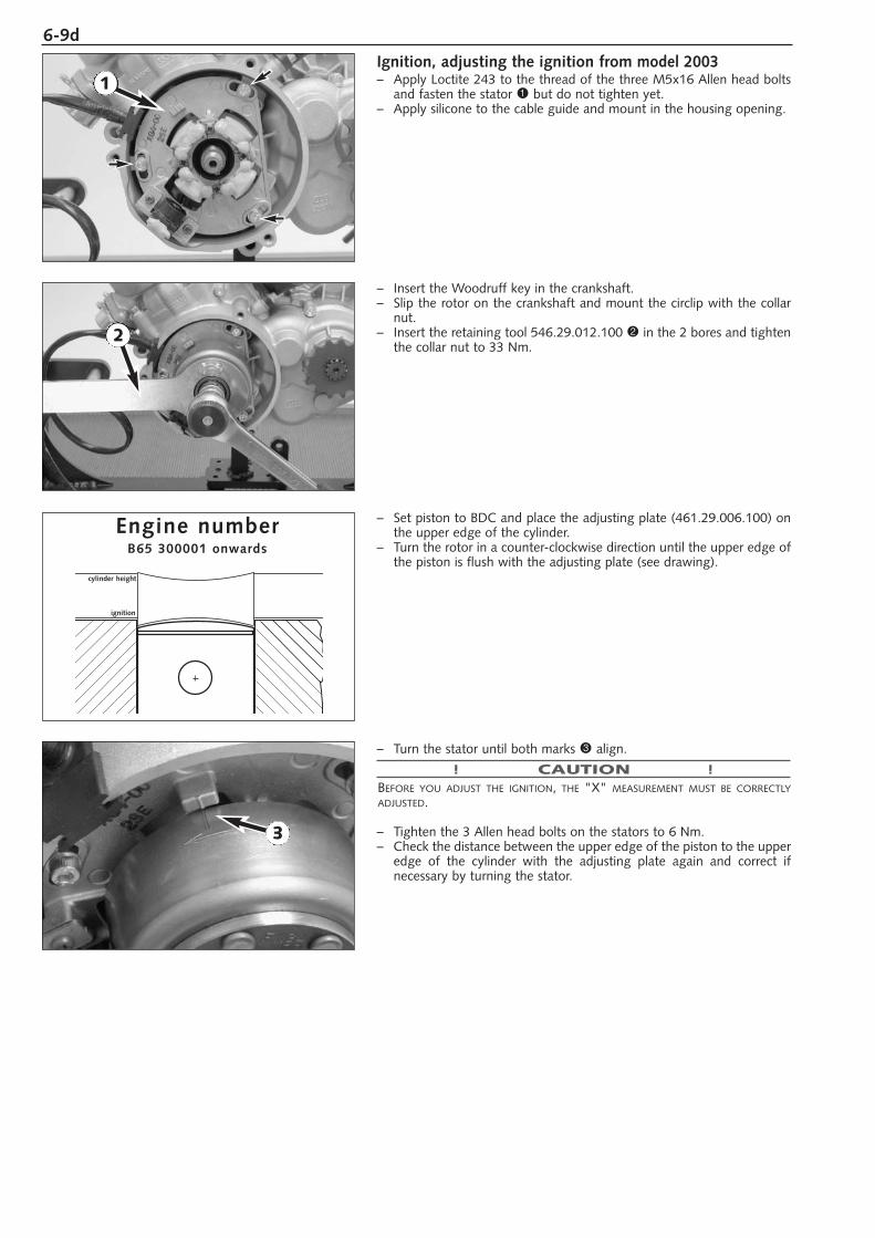
Ignition, adjusting the ignition from model 2003– Apply Loctite 243 to the thread of the three M5x16 Allen head bolts
and fasten the stator 1 but do not tighten yet.– Apply silicone to the cable guide and mount in the housing opening.
– Insert the Woodruff key in the crankshaft.– Slip the rotor on the crankshaft and mount the circlip with the collar
nut.– Insert the retaining tool 546.29.012.100 2 in the 2 bores and tighten
the collar nut to 33 Nm.
– Set piston to BDC and place the adjusting plate (461.29.006.100) onthe upper edge of the cylinder.
– Turn the rotor in a counter-clockwise direction until the upper edge ofthe piston is flush with the adjusting plate (see drawing).
– Turn the stator until both marks 3 align.
! CAUTION !BEFORE YOU ADJUST THE IGNITION, THE "X" MEASUREMENT MUST BE CORRECTLYADJUSTED.
– Tighten the 3 Allen head bolts on the stators to 6 Nm.– Check the distance between the upper edge of the piston to the upper
edge of the cylinder with the adjusting plate again and correct ifnecessary by turning the stator.
2
Engine numberB65 300001 onwards
cylinder height
ignition
1
3
6-10dR
epai
r m
anua
l K
TM 6
0 SX
+ 6
5 SX
A
rt.-
No.
32
1066
-E
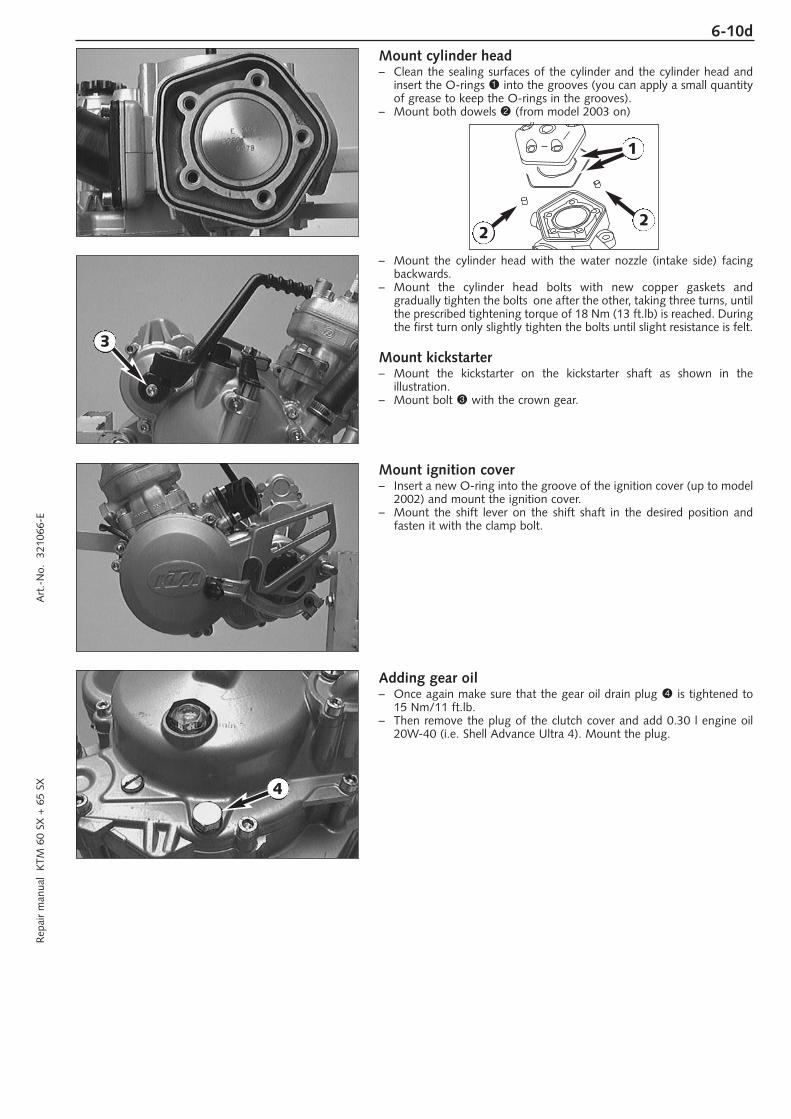
Mount cylinder head– Clean the sealing surfaces of the cylinder and the cylinder head and
insert the O-rings 1 into the grooves (you can apply a small quantityof grease to keep the O-rings in the grooves).
– Mount both dowels 2 (from model 2003 on)
– Mount the cylinder head with the water nozzle (intake side) facingbackwards.
– Mount the cylinder head bolts with new copper gaskets and gradually tighten the bolts one after the other, taking three turns, untilthe prescribed tightening torque of 18 Nm (13 ft.lb) is reached. Duringthe first turn only slightly tighten the bolts until slight resistance is felt.
Mount kickstarter– Mount the kickstarter on the kickstarter shaft as shown in the
illustration.– Mount bolt 3 with the crown gear.
Mount ignition cover– Insert a new O-ring into the groove of the ignition cover (up to model
2002) and mount the ignition cover.– Mount the shift lever on the shift shaft in the desired position and
fasten it with the clamp bolt.
Adding gear oil– Once again make sure that the gear oil drain plug 4 is tightened to
15 Nm/11 ft.lb.– Then remove the plug of the clutch cover and add 0.30 l engine oil
20W-40 (i.e. Shell Advance Ultra 4). Mount the plug.
1
22
3
4

TROUBLE SHOOTING
TROUBLE SHOOTING 60 SX / 65 SX . . . . . . . . . . . . . . . . . . . . . . . . . . . .7-2
RESISTOR VALUES OF THE IGNITION SYSTEM . . . . . . . . . . . . . . . . . . . . .7-4
MEASUREMENT WITH PEAK VOLTAGE ADAPTER . . . . . . . . . . . . . . . . . . .7-5
INDEX
7R
epai
r m
anua
l K
TM 6
0 SX
+ 6
5 SX
A
rt.-
No.
32
1066
-E
7-1d

7-2dR
epai
r m
anua
l K
TM 6
0 SX
+ 6
5 SX
A
rt.-
No.
32
1066
-E
CAUSE
Operating error
Fuel supply interrupted
Electrode distance too great
Plug fouled by oil, wet or bridged
Ignition wire or spark plug connector damaged
Kill button wire or short-circuit switch faulty
Loose ignition cable connectors
Spark too weak
Water in the carburetor and jetsblocked
Idle adjusting screw out of adjustment
Ignition system damaged
Wear
Charred glass fiber yarn in silencer
Air filter obstructed
Fuel supply partly interrupted orblocked
Loss of compression through loosespark plug
Exhaust system damaged
Engine has not enough preignition
REMEDY
Open fuel tap, replenish fuel, do not use choke
Close fuel tap, loosen fuel hose at carburettor, lead into abasin and open fuel tap,– if fuel leaks out, clean carburettor– if no fuel leaks out, check tank ventilation, i.e. clean fuel tap
Reduce electrode distance (0.60 mm)
Clean spark plug or renew
Dismount spark plug, connect ignition cable, hold to ground(blank place on engine) and actuate kickstarter, a strong sparkmust be produced at the spark plug– If no spark is produced, loosen spark plug cap from ignition
cable, hold about 5 mm from ground and actuate kickstarter– If a spark now occurs, replace spark plug cap– If no spark is produced, control ignition system
Disconnect black coloured cable from short circuit button atignition coil and check ignition spark. If the spark is O.K. repairdefective part of cable or ignition switch
Inspect cable connectors
Examine ignition system
Dismantle and clean carburetor
Readjust idle running or replace idle adjusting screw
Examine ignition system
Overhaul engine
Renew filling
Clean or renew airfilter
Blow through fuel pipe and clean carburetor
Tighten spark plug
Check exhaust system for damage
Check and adjust ignition
TROUBLE
Engine fails to start
Engine without idle running
Engine has not enoughpower
7-3d
TROUBLE
Engine has not enoughpower
Engine revs not up andrunning in four strokecycle
High rpm misfiring
Engine spluters into thecarburetor
Engine overheating
Emission of white smoke(steam)
Excessive oil escapes fromtransmission breather tube
Water in transmission oil
CAUSE
Reed paddles tensionless or damaged,surface of reed valve housing damaged
Wear
Carburetor overflows if level adjusttoo high, float needle seating isdirty or enlarged
Loose carburetor jets
Incorrect heat range spark plug or low quality spark plug
Loose, corroded or non conductiveignition socket connector
Lack of fuel
Spark plug with incorrect heat value(Ignition by incandescence)
Engine takes air out of control
Insufficient liquid in cooling system
Radiator fins clogged
Frothing in cooling system
Pinched or kinked water hoses
Incorrect ignition timing because ofloose stator bolts
Incorrect compression ratio
Cylinder head or O-ring of cylinderhead gasket leaks
Excessive oil quantity in transmissi-on
Shaft seal ring of the water pumpdefect
REMEDY
Replace reed paddles or reed valve housing
Overhaul engine
Clean carburetor, if necessary replace float needle and adjustlevel
Tighten jets
Refer to technical data section
Check and seal with silicon
Clean fuel pipes, examine tank aeration and clean
Fit correct spark plug
Check intake flange and carburettor if firmly setted
Top up coolant and bleed cooling system check cooling systemfor leaks
Clean radiatar fins with water jet
Renew coolant using branded anti-freeze/anti-corrosive (ShellAdvance Coolant)
Replace with correct routed hoses
Readjust to correct ignition timing specifications, secure bolts with Loctite 243
Measure and adjust compression ratio
Check cylinder head, replace O-ring
Correct transmission oil level
Replace shaft seal ring of the water pump.
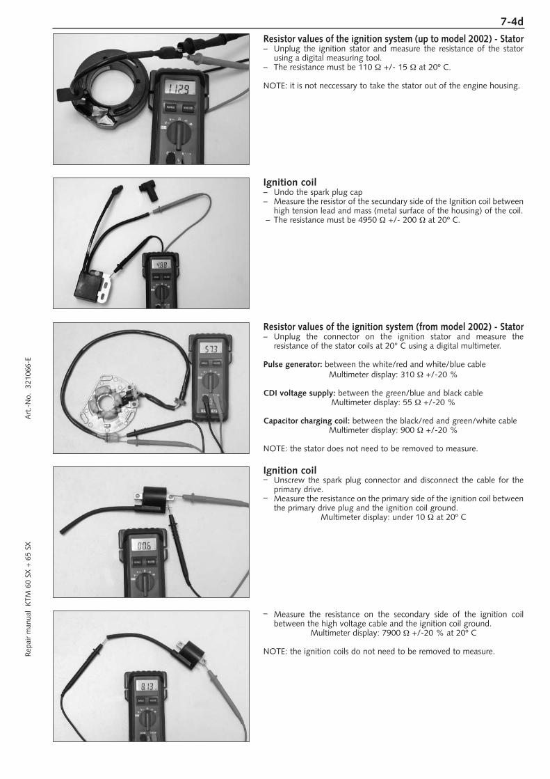
7-4dR
epai
r m
anua
l K
TM 6
0 SX
+ 6
5 SX
A
rt.-
No.
32
1066
-E
Resistor values of the ignition system (up to model 2002) - Stator– Unplug the ignition stator and measure the resistance of the stator
using a digital measuring tool.– The resistance must be 110 Ω +/- 15 Ω at 20º C.
NOTE: it is not neccessary to take the stator out of the engine housing.
Ignition coil– Undo the spark plug cap– Measure the resistor of the secundary side of the Ignition coil between
high tension lead and mass (metal surface of the housing) of the coil.– The resistance must be 4950 Ω +/- 200 Ω at 20º C.
Resistor values of the ignition system (from model 2002) - Stator– Unplug the connector on the ignition stator and measure the
resistance of the stator coils at 20° C using a digital multimeter.
Pulse generator: between the white/red and white/blue cableMultimeter display: 310 Ω +/-20 %
CDI voltage supply: between the green/blue and black cableMultimeter display: 55 Ω +/-20 %
Capacitor charging coil: between the black/red and green/white cableMultimeter display: 900 Ω +/-20 %
NOTE: the stator does not need to be removed to measure.
Ignition coil– Unscrew the spark plug connector and disconnect the cable for the
primary drive.– Measure the resistance on the primary side of the ignition coil between
the primary drive plug and the ignition coil ground.Multimeter display: under 10 Ω at 20º C
– Measure the resistance on the secondary side of the ignition coil between the high voltage cable and the ignition coil ground.
Multimeter display: 7900 Ω +/-20 % at 20º C
NOTE: the ignition coils do not need to be removed to measure.
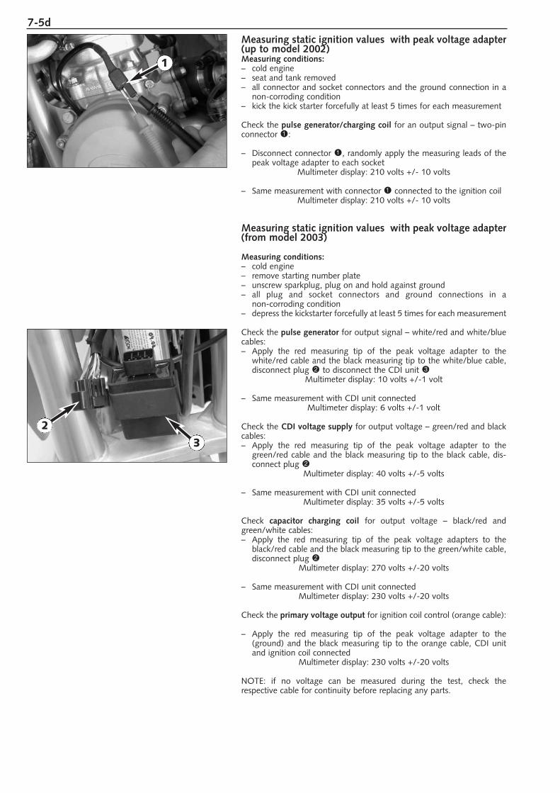
7-5d
Measuring static ignition values with peak voltage adapter(up to model 2002)Measuring conditions:– cold engine– seat and tank removed– all connector and socket connectors and the ground connection in a
non-corroding condition– kick the kick starter forcefully at least 5 times for each measurement
Check the pulse generator/charging coil for an output signal – two-pinconnector 1:
– Disconnect connector 1, randomly apply the measuring leads of thepeak voltage adapter to each socket
Multimeter display: 210 volts +/- 10 volts
– Same measurement with connector 1 connected to the ignition coilMultimeter display: 210 volts +/- 10 volts
Measuring static ignition values with peak voltage adapter(from model 2003)
Measuring conditions:– cold engine – remove starting number plate– unscrew sparkplug, plug on and hold against ground – all plug and socket connectors and ground connections in a
non-corroding condition– depress the kickstarter forcefully at least 5 times for each measurement
Check the pulse generator for output signal – white/red and white/bluecables:– Apply the red measuring tip of the peak voltage adapter to the
white/red cable and the black measuring tip to the white/blue cable,disconnect plug 2 to disconnect the CDI unit 3
Multimeter display: 10 volts +/-1 volt
– Same measurement with CDI unit connectedMultimeter display: 6 volts +/-1 volt
Check the CDI voltage supply for output voltage – green/red and blackcables:– Apply the red measuring tip of the peak voltage adapter to the
green/red cable and the black measuring tip to the black cable, dis-connect plug 2
Multimeter display: 40 volts +/-5 volts
– Same measurement with CDI unit connectedMultimeter display: 35 volts +/-5 volts
Check capacitor charging coil for output voltage – black/red andgreen/white cables:– Apply the red measuring tip of the peak voltage adapters to the
black/red cable and the black measuring tip to the green/white cable, disconnect plug 2
Multimeter display: 270 volts +/-20 volts
– Same measurement with CDI unit connectedMultimeter display: 230 volts +/-20 volts
Check the primary voltage output for ignition coil control (orange cable):
– Apply the red measuring tip of the peak voltage adapter to the (ground) and the black measuring tip to the orange cable, CDI unitand ignition coil connected
Multimeter display: 230 volts +/-20 volts
NOTE: if no voltage can be measured during the test, check the respective cable for continuity before replacing any parts.
1
3
2
TECHNICAL SPECIFICATIONS
TECHNICAL SPECIFICATIONS MODEL 1998/99
ENGINE . . . . . . . . . . . . . . . . . . . . . . . . . . . . . . . . . . . . . . . . . . . . .8-2
BASIC CARBURETOR SETTING . . . . . . . . . . . . . . . . . . . . . . . . . . . . .8-2
CHASSIS . . . . . . . . . . . . . . . . . . . . . . . . . . . . . . . . . . . . . . . . . . . . .8-3
STANDARD-ADJUSTMENT – FORK . . . . . . . . . . . . . . . . . . . . . . . . . .8-3
TECHNICAL SPECIFICATIONS MODEL 2000
ENGINE . . . . . . . . . . . . . . . . . . . . . . . . . . . . . . . . . . . . . . . . . . . . .8-4
BASIC CARBURETOR SETTING . . . . . . . . . . . . . . . . . . . . . . . . . . . . .8-4
CHASSIS . . . . . . . . . . . . . . . . . . . . . . . . . . . . . . . . . . . . . . . . . . . . .8-5
STANDARD-ADJUSTMENT – FORK . . . . . . . . . . . . . . . . . . . . . . . . . .8-5
TECHNICAL SPECIFICATIONS MODEL 2001
ENGINE . . . . . . . . . . . . . . . . . . . . . . . . . . . . . . . . . . . . . . . . . . . . .8-6
BASIC CARBURETOR SETTING . . . . . . . . . . . . . . . . . . . . . . . . . . . . .8-6
CHASSIS . . . . . . . . . . . . . . . . . . . . . . . . . . . . . . . . . . . . . . . . . . . . .8-7
STANDARD-ADJUSTMENT – FORK . . . . . . . . . . . . . . . . . . . . . . . . . .8-7
TECHNICAL SPECIFICATIONS MODEL 2002
ENGINE . . . . . . . . . . . . . . . . . . . . . . . . . . . . . . . . . . . . . . . . . . . . .8-8
BASIC CARBURETOR SETTING . . . . . . . . . . . . . . . . . . . . . . . . . . . . .8-8
CHASSIS . . . . . . . . . . . . . . . . . . . . . . . . . . . . . . . . . . . . . . . . . . . . .8-9
STANDARD-ADJUSTMENT – FORK / SHOCK ABSORBER . . . . . . . . . .8-9
TECHNICAL SPECIFICATIONS MODEL 2003
ENGINE . . . . . . . . . . . . . . . . . . . . . . . . . . . . . . . . . . . . . . . . . . . . .8-10
BASIC CARBURETOR SETTING . . . . . . . . . . . . . . . . . . . . . . . . . . . .8-10
CHASSIS . . . . . . . . . . . . . . . . . . . . . . . . . . . . . . . . . . . . . . . . . . . .8-11
STANDARD-ADJUSTMENT – FORK / SHOCK ABSORBER . . . . . . . . .8-11
TOLERANCE, ASSEMBLY CLEARANCE . . . . . . . . . . . . . . . . . . . . . . .8-12
TIGHTENING TORQUES – ENGINE . . . . . . . . . . . . . . . . . . . . . . . . .8-12
TIGHTENING TORQUES – CHASSIS . . . . . . . . . . . . . . . . . . . . . . . . .8-12
INDEX
8R
epai
r m
anua
l K
TM 6
0 SX
+ 6
5 SX
A
rt.-
No.
32
1066
-E
8-1d

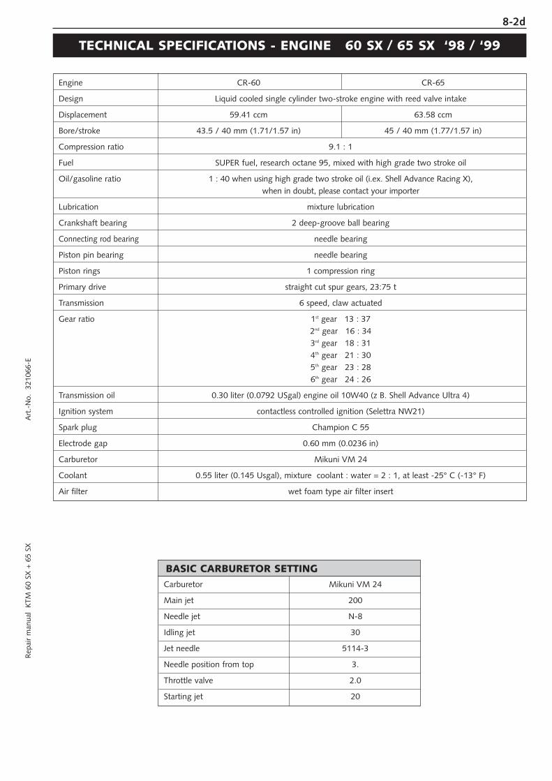
8-2dR
epai
r m
anua
l K
TM 6
0 SX
+ 6
5 SX
A
rt.-
No.
32
1066
-E
Engine CR-60 CR-65
Design Liquid cooled single cylinder two-stroke engine with reed valve intake
Displacement 59.41 ccm 63.58 ccm
Bore/stroke 43.5 / 40 mm (1.71/1.57 in) 45 / 40 mm (1.77/1.57 in)
Compression ratio 9.1 : 1
Fuel SUPER fuel, research octane 95, mixed with high grade two stroke oil
Oil/gasoline ratio 1 : 40 when using high grade two stroke oil (i.ex. Shell Advance Racing X), when in doubt, please contact your importer
Lubrication mixture lubrication
Crankshaft bearing 2 deep-groove ball bearing
Connecting rod bearing needle bearing
Piston pin bearing needle bearing
Piston rings 1 compression ring
Primary drive straight cut spur gears, 23:75 t
Transmission 6 speed, claw actuated
Gear ratio 1st gear 13 : 372nd gear 16 : 343rd gear 18 : 314th gear 21 : 305th gear 23 : 286th gear 24 : 26
Transmission oil 0.30 liter (0.0792 USgal) engine oil 10W40 (z B. Shell Advance Ultra 4)
Ignition system contactless controlled ignition (Selettra NW21)
Spark plug Champion C 55
Electrode gap 0.60 mm (0.0236 in)
Carburetor Mikuni VM 24
Coolant 0.55 liter (0.145 Usgal), mixture coolant : water = 2 : 1, at least -25° C (-13° F)
Air filter wet foam type air filter insert
TECHNICAL SPECIFICATIONS - ENGINE 60 SX / 65 SX ‘98 / ‘99
Carburetor Mikuni VM 24
Main jet 200
Needle jet N-8
Idling jet 30
Jet needle 5114-3
Needle position from top 3.
Throttle valve 2.0
Starting jet 20
BASIC CARBURETOR SETTING
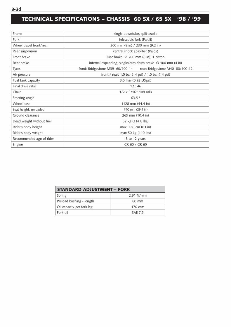
8-3d
Frame single downtube, split-cradle
Fork telescopic fork (Paioli)
Wheel travel front/rear 200 mm (8 in) / 230 mm (9.2 in)
Rear suspension central shock absorber (Paioli)
Front brake Disc brake Ø 200 mm (8 in), 1 piston
Rear brake internal expanding, single/cam drum brake Ø 100 mm (4 in)
Tyres front: Bridgestone M39 60/100-14 rear: Bridgestone M40 80/100-12
Air pressure front / rear: 1.0 bar (14 psi) / 1.0 bar (14 psi)
Fuel tank capacity 3.5 liter (0.92 USgal)
Final drive ratio 12 : 46
Chain 1/2 x 3/16" 108 rolls
Steering angle 63.5 °
Wheel base 1128 mm (44.4 in)
Seat height, unloaded 740 mm (29.1 in)
Ground clearance 265 mm (10.4 in)
Dead weight without fuel 52 kg (114.8 lbs)
Rider’s body height max. 160 cm (63 in)
Rider’s body weight max 50 kg (110 lbs)
Recommended age of rider 8 to 12 years
Engine CR 60 / CR 65
TECHNICAL SPECIFICATIONS – CHASSIS 60 SX / 65 SX ‘98 / ‘99
Spring 2.91 N/mm
Preload bushing - length 80 mm
Oil capacity per fork leg 170 ccm
Fork oil SAE 7,5
STANDARD ADJUSTMENT – FORK
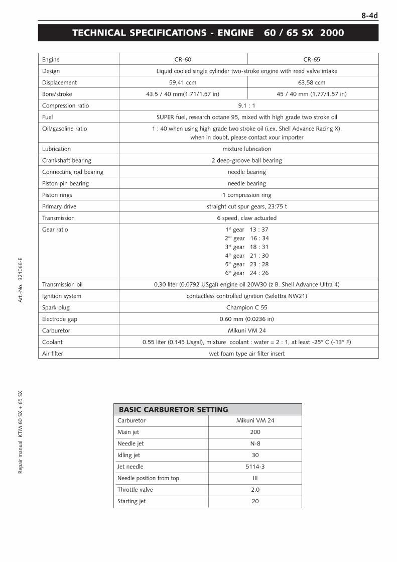
8-4dR
epai
r m
anua
l K
TM 6
0 SX
+ 6
5 SX
A
rt.-
No.
32
1066
-E
Engine CR-60 CR-65
Design Liquid cooled single cylinder two-stroke engine with reed valve intake
Displacement 59,41 ccm 63,58 ccm
Bore/stroke 43.5 / 40 mm(1.71/1.57 in) 45 / 40 mm (1.77/1.57 in)
Compression ratio 9.1 : 1
Fuel SUPER fuel, research octane 95, mixed with high grade two stroke oil
Oil/gasoline ratio 1 : 40 when using high grade two stroke oil (i.ex. Shell Advance Racing X), when in doubt, please contact xour importer
Lubrication mixture lubrication
Crankshaft bearing 2 deep-groove ball bearing
Connecting rod bearing needle bearing
Piston pin bearing needle bearing
Piston rings 1 compression ring
Primary drive straight cut spur gears, 23:75 t
Transmission 6 speed, claw actuated
Gear ratio 1st gear 13 : 372nd gear 16 : 343rd gear 18 : 314th gear 21 : 305th gear 23 : 286th gear 24 : 26
Transmission oil 0,30 liter (0,0792 USgal) engine oil 20W30 (z B. Shell Advance Ultra 4)
Ignition system contactless controlled ignition (Selettra NW21)
Spark plug Champion C 55
Electrode gap 0.60 mm (0.0236 in)
Carburetor Mikuni VM 24
Coolant 0.55 liter (0.145 Usgal), mixture coolant : water = 2 : 1, at least -25° C (-13° F)
Air filter wet foam type air filter insert
TECHNICAL SPECIFICATIONS - ENGINE 60 / 65 SX 2000
Carburetor Mikuni VM 24
Main jet 200
Needle jet N-8
Idling jet 30
Jet needle 5114-3
Needle position from top III
Throttle valve 2.0
Starting jet 20
BASIC CARBURETOR SETTING
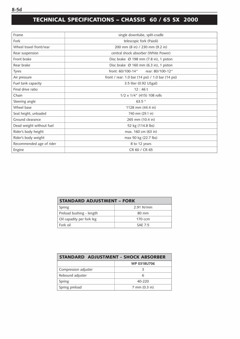
8-5d
Spring 2.91 N/mm
Preload bushing - length 80 mm
Oil capadity per fork leg 170 ccm
Fork oil SAE 7.5
STANDARD ADJUSTMENT – FORK
WP 0318U706
Compression adjuster 3
Rebound adjuster 6
Spring 40-220
Spring preload 7 mm (0.3 in)
STANDARD ADJUSTMENT - SHOCK ABSORBER
Frame single downtube, split-cradle
Fork telescopic fork (Paioli)
Wheel travel front/rear 200 mm (8 in) / 230 mm (9.2 in)
Rear suspension central shock absorber (White Power)
Front brake Disc brake Ø 198 mm (7.8 in), 1 piston
Rear brake Disc brake Ø 160 mm (6.3 in), 1 piston
Tyres front: 60/100-14“ rear: 80/100-12“
Air pressure front / rear: 1.0 bar (14 psi) / 1.0 bar (14 psi)
Fuel tank capacity 3.5 liter (0.92 USgal)
Final drive ratio 12 : 46 t
Chain 1/2 x 1/4" (415) 108 rolls
Steering angle 63.5 °
Wheel base 1128 mm (44.4 in)
Seat height, unloaded 740 mm (29.1 in)
Ground clearance 265 mm (10.4 in)
Dead weight without fuel 52 kg (114.8 lbs)
Rider’s body height max. 160 cm (63 in)
Rider’s body weight max 50 kg (22.7 lbs)
Recommended age of rider 8 to 12 years
Engine CR 60 / CR 65
TECHNICAL SPECIFICATIONS – CHASSIS 60 / 65 SX 2000
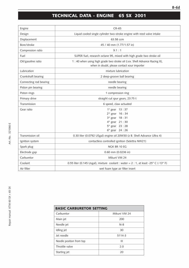
8-6dR
epai
r m
anua
l K
TM 6
0 SX
+ 6
5 SX
A
rt.-
No.
32
1066
-E
Engine CR-65
Design Liquid cooled single cylinder two-stroke engine with reed valve intake
Displacement 63.58 ccm
Bore/stroke 45 / 40 mm (1.77/1.57 in)
Compression ratio 9.1 : 1
Fuel SUPER fuel, research octane 95, mixed with high grade two stroke oil
Oil/gasoline ratio 1 : 40 when using high grade two stroke oil (i.ex. Shell Advance Racing X), when in doubt, please contact xour importer
Lubrication mixture lubrication
Crankshaft bearing 2 deep-groove ball bearing
Connecting rod bearing needle bearing
Piston pin bearing needle bearing
Piston rings 1 compression ring
Primary drive straight cut spur gears, 23:75 t
Transmission 6 speed, claw actuated
Gear ratio 1st gear 13 : 372nd gear 16 : 343rd gear 18 : 314th gear 21 : 305th gear 23 : 286th gear 24 : 26
Transmission oil 0.30 liter (0.0792 USgal) engine oil 20W30 (z B. Shell Advance Ultra 4)
Ignition system contactless controlled ignition (Selettra NW21)
Spark plug NGK BR 10 EG
Electrode gap 0.60 mm (0.0236 in)
Carburetor Mikuni VM 24
Coolant 0.55 liter (0.145 Usgal), mixture coolant : water = 2 : 1, at least -25° C (-13° F)
Air filter wet foam type air filter insert
TECHNICAL DATA - ENGINE 65 SX 2001
Carburetor Mikuni VM 24
Main jet 200
Needle jet N-8
Idling jet 30
Jet needle 5114-3
Needle position from top III
Throttle valve 2.0
Starting jet 20
BASIC CARBURETOR SETTING
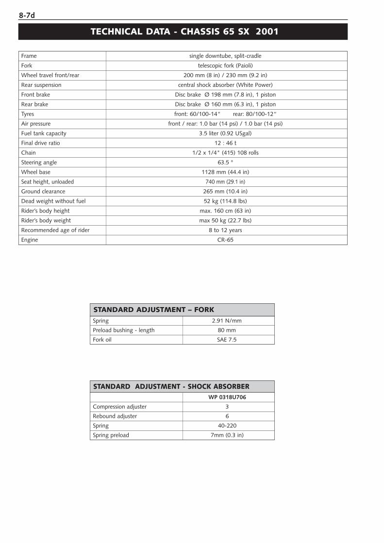
8-7d
Spring 2.91 N/mm
Preload bushing - length 80 mm
Fork oil SAE 7.5
STANDARD ADJUSTMENT – FORK
WP 0318U706
Compression adjuster 3
Rebound adjuster 6
Spring 40-220
Spring preload 7mm (0.3 in)
STANDARD ADJUSTMENT - SHOCK ABSORBER
Frame single downtube, split-cradle
Fork telescopic fork (Paioli)
Wheel travel front/rear 200 mm (8 in) / 230 mm (9.2 in)
Rear suspension central shock absorber (White Power)
Front brake Disc brake Ø 198 mm (7.8 in), 1 piston
Rear brake Disc brake Ø 160 mm (6.3 in), 1 piston
Tyres front: 60/100-14“ rear: 80/100-12“
Air pressure front / rear: 1.0 bar (14 psi) / 1.0 bar (14 psi)
Fuel tank capacity 3.5 liter (0.92 USgal)
Final drive ratio 12 : 46 t
Chain 1/2 x 1/4" (415) 108 rolls
Steering angle 63.5 °
Wheel base 1128 mm (44.4 in)
Seat height, unloaded 740 mm (29.1 in)
Ground clearance 265 mm (10.4 in)
Dead weight without fuel 52 kg (114.8 lbs)
Rider’s body height max. 160 cm (63 in)
Rider’s body weight max 50 kg (22.7 lbs)
Recommended age of rider 8 to 12 years
Engine CR-65
TECHNICAL DATA - CHASSIS 65 SX 2001
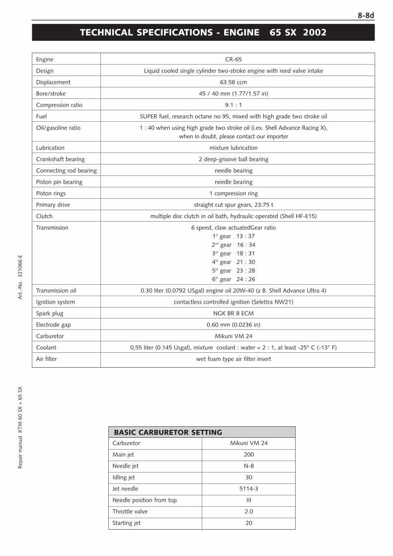
8-8dR
epai
r m
anua
l K
TM 6
0 SX
+ 6
5 SX
A
rt.-
No.
32
1066
-E
Engine CR-65
Design Liquid cooled single cylinder two-stroke engine with reed valve intake
Displacement 63.58 ccm
Bore/stroke 45 / 40 mm (1.77/1.57 in)
Compression ratio 9.1 : 1
Fuel SUPER fuel, research octane no 95, mixed with high grade two stroke oil
Oil/gasoline ratio 1 : 40 when using high grade two stroke oil (i.ex. Shell Advance Racing X), when in doubt, please contact our importer
Lubrication mixture lubrication
Crankshaft bearing 2 deep-groove ball bearing
Connecting rod bearing needle bearing
Piston pin bearing needle bearing
Piston rings 1 compression ring
Primary drive straight cut spur gears, 23:75 t
Clutch multiple disc clutch in oil bath, hydraulic operated (Shell HF-E15)
Transmission 6 speed, claw actuatedGear ratio1st gear 13 : 372nd gear 16 : 343rd gear 18 : 314th gear 21 : 305th gear 23 : 286th gear 24 : 26
Transmission oil 0.30 liter (0.0792 USgal) engine oil 20W-40 (z B. Shell Advance Ultra 4)
Ignition system contactless controlled ignition (Selettra NW21)
Spark plug NGK BR 8 ECM
Electrode gap 0.60 mm (0.0236 in)
Carburetor Mikuni VM 24
Coolant 0,55 liter (0.145 Usgal), mixture coolant : water = 2 : 1, at least -25° C (-13° F)
Air filter wet foam type air filter insert
TECHNICAL SPECIFICATIONS - ENGINE 65 SX 2002
Carburetor Mikuni VM 24
Main jet 200
Needle jet N-8
Idling jet 30
Jet needle 5114-3
Needle position from top III
Throttle valve 2.0
Starting jet 20
BASIC CARBURETOR SETTING
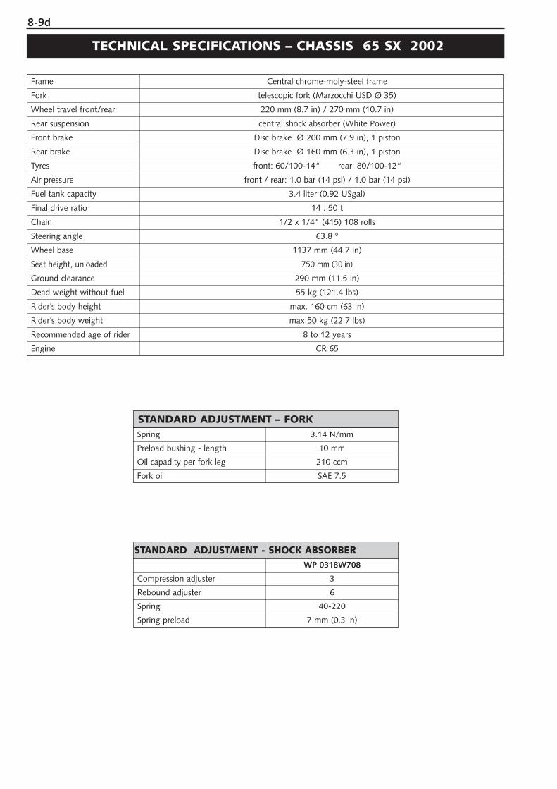
8-9d
Spring 3.14 N/mm
Preload bushing - length 10 mm
Oil capadity per fork leg 210 ccm
Fork oil SAE 7.5
STANDARD ADJUSTMENT – FORK
WP 0318W708
Compression adjuster 3
Rebound adjuster 6
Spring 40-220
Spring preload 7 mm (0.3 in)
STANDARD ADJUSTMENT - SHOCK ABSORBER
Frame Central chrome-moly-steel frame
Fork telescopic fork (Marzocchi USD Ø 35)
Wheel travel front/rear 220 mm (8.7 in) / 270 mm (10.7 in)
Rear suspension central shock absorber (White Power)
Front brake Disc brake Ø 200 mm (7.9 in), 1 piston
Rear brake Disc brake Ø 160 mm (6.3 in), 1 piston
Tyres front: 60/100-14“ rear: 80/100-12“
Air pressure front / rear: 1.0 bar (14 psi) / 1.0 bar (14 psi)
Fuel tank capacity 3.4 liter (0.92 USgal)
Final drive ratio 14 : 50 t
Chain 1/2 x 1/4" (415) 108 rolls
Steering angle 63.8 °
Wheel base 1137 mm (44.7 in)
Seat height, unloaded 750 mm (30 in)
Ground clearance 290 mm (11.5 in)
Dead weight without fuel 55 kg (121.4 lbs)
Rider’s body height max. 160 cm (63 in)
Rider’s body weight max 50 kg (22.7 lbs)
Recommended age of rider 8 to 12 years
Engine CR 65
TECHNICAL SPECIFICATIONS – CHASSIS 65 SX 2002
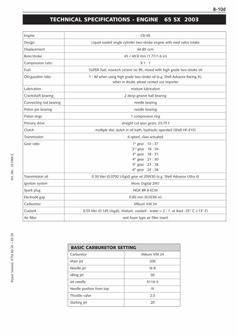
8-10dR
epai
r m
anua
l K
TM 6
0 SX
+ 6
5 SX
A
rt.-
No.
32
1066
-E
Engine CR-65
Design Liquid cooled single cylinder two-stroke engine with reed valve intake
Displacement 64.85 ccm
Bore/stroke 45 / 40.8 mm (1.77/1.6 in)
Compression ratio 9.1 : 1
Fuel SUPER fuel, research octane no 95, mixed with high grade two-stroke oil
Oil/gasoline ratio 1 : 40 when using high grade two-stroke oil (e.g. Shell Advance Racing X), when in doubt, please contact our importer
Lubrication mixture lubrication
Crankshaft bearing 2 deep-groove ball bearing
Connecting rod bearing needle bearing
Piston pin bearing needle bearing
Piston rings 1 compression ring
Primary drive straight cut spur gears, 23:75 t
Clutch multiple disc clutch in oil bath, hydraulic operated (Shell HF-E15)
Transmission 6 speed, claw actuated
Gear ratio 1st gear 13 : 372nd gear 16 : 343rd gear 18 : 314th gear 21 : 305th gear 23 : 286th gear 24 : 26
Transmission oil 0.30 liter (0.0792 USgal) gear oil 20W30 (e.g. Shell Advance Ultra 4)
Ignition system Moric Digital 2M1
Spark plug NGK BR 8 ECM
Electrode gap 0.60 mm (0.0236 in)
Carburetor Mikuni VM 24
Coolant 0.55 liter (0.145 Usgal), mixture coolant : water = 2 : 1, at least -25° C (-13° F)
Air filter wet foam type air filter insert
TECHNICAL SPECIFICATIONS - ENGINE 65 SX 2003
Carburetor Mikuni VM 24
Main jet 200
Needle jet N-8
Idling jet 30
Jet needle 5114-3
Needle position from top III
Throttle valve 2.0
Starting jet 20
BASIC CARBURETOR SETTING
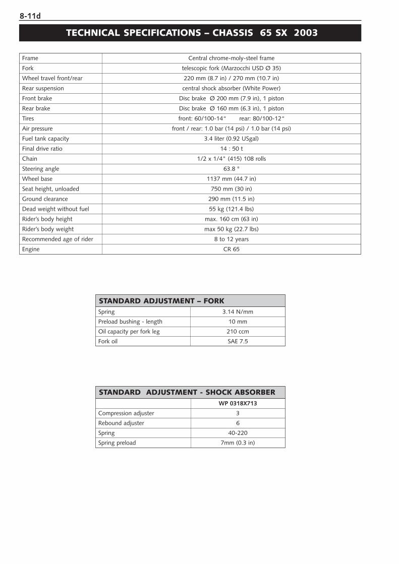
8-11d
Spring 3.14 N/mm
Preload bushing - length 10 mm
Oil capacity per fork leg 210 ccm
Fork oil SAE 7.5
STANDARD ADJUSTMENT – FORK
WP 0318X713
Compression adjuster 3
Rebound adjuster 6
Spring 40-220
Spring preload 7mm (0.3 in)
STANDARD ADJUSTMENT - SHOCK ABSORBER
Frame Central chrome-moly-steel frame
Fork telescopic fork (Marzocchi USD Ø 35)
Wheel travel front/rear 220 mm (8.7 in) / 270 mm (10.7 in)
Rear suspension central shock absorber (White Power)
Front brake Disc brake Ø 200 mm (7.9 in), 1 piston
Rear brake Disc brake Ø 160 mm (6.3 in), 1 piston
Tires front: 60/100-14“ rear: 80/100-12“
Air pressure front / rear: 1.0 bar (14 psi) / 1.0 bar (14 psi)
Fuel tank capacity 3.4 liter (0.92 USgal)
Final drive ratio 14 : 50 t
Chain 1/2 x 1/4" (415) 108 rolls
Steering angle 63.8 °
Wheel base 1137 mm (44.7 in)
Seat height, unloaded 750 mm (30 in)
Ground clearance 290 mm (11.5 in)
Dead weight without fuel 55 kg (121.4 lbs)
Rider’s body height max. 160 cm (63 in)
Rider’s body weight max 50 kg (22.7 lbs)
Recommended age of rider 8 to 12 years
Engine CR 65
TECHNICAL SPECIFICATIONS – CHASSIS 65 SX 2003
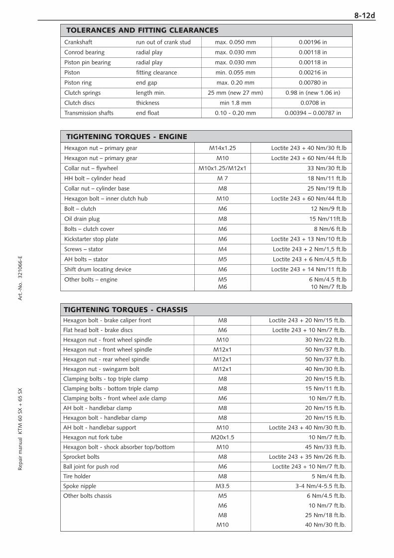
8-12dR
epai
r m
anua
l K
TM 6
0 SX
+ 6
5 SX
A
rt.-
No.
32
1066
-E
Hexagon bolt - brake caliper front M8 Loctite 243 + 20 Nm/15 ft.lb.
Flat head bolt - brake discs M6 Loctite 243 + 10 Nm/7 ft.lb.
Hexagon nut - front wheel spindle M10 30 Nm/22 ft.lb.
Hexagon nut - front wheel spindle M12x1 50 Nm/37 ft.lb.
Hexagon nut - rear wheel spindle M12x1 50 Nm/37 ft.lb.
Hexagon nut - swingarm bolt M12x1 40 Nm/30 ft.lb.
Clamping bolts - top triple clamp M8 20 Nm/15 ft.lb.
Clamping bolts - bottom triple clamp M8 15 Nm/11 ft.lb.
Clamping bolts - front wheel axle clamp M6 10 Nm/7 ft.lb.
AH bolt - handlebar clamp M8 20 Nm/15 ft.lb.
Hexagon bolt - handlebar clamp M8 20 Nm/15 ft.lb.
AH bolt - handlebar support M10 Loctite 243 + 40 Nm/30 ft.lb.
Hexagon nut fork tube M20x1.5 10 Nm/7 ft.lb.
Hexagon bolt - shock absorber top/bottom M10 45 Nm/33 ft.lb.
Sprocket bolts M8 Loctite 243 + 35 Nm/26 ft.lb.
Ball joint for push rod M6 Loctite 243 + 10 Nm/7 ft.lb.
Tire holder M8 5 Nm/4 ft.lb.
Spoke nipple M3.5 3-4 Nm/4-5.5 ft.lb.
Other bolts chassis M5 6 Nm/4.5 ft.lb.
M6 10 Nm/7 ft.lb.
M8 25 Nm/18 ft.lb.
M10 40 Nm/30 ft.lb.
TIGHTENING TORQUES - CHASSIS
Hexagon nut – primary gear M14x1.25 Loctite 243 + 40 Nm/30 ft.lb
Hexagon nut – primary gear M10 Loctite 243 + 60 Nm/44 ft.lb
Collar nut – flywheel M10x1.25/M12x1 33 Nm/30 ft.lb
HH bolt – cylinder head M 7 18 Nm/11 ft.lb
Collar nut – cylinder base M8 25 Nm/19 ft.lb
Hexagon bolt – inner clutch hub M10 Loctite 243 + 60 Nm/44 ft.lb
Bolt – clutch M6 12 Nm/9 ft.lb
Oil drain plug M8 15 Nm/11ft.lb
Bolts – clutch cover M6 8 Nm/6 ft.lb
Kickstarter stop plate M6 Loctite 243 + 13 Nm/10 ft.lb
Screws – stator M4 Loctite 243 + 2 Nm/1,5 ft.lb
AH bolts – stator M5 Loctite 243 + 6 Nm/4,5 ft.lb
Shift drum locating device M6 Loctite 243 + 14 Nm/11 ft.lb
Other bolts – engine M5 6 Nm/4.5 ft.lbM6 10 Nm/7 ft.lb
TIGHTENING TORQUES - ENGINE
Crankshaft run out of crank stud max. 0.050 mm 0.00196 in
Conrod bearing radial play max. 0.030 mm 0.00118 in
Piston pin bearing radial play max. 0.030 mm 0.00118 in
Piston fitting clearance min. 0.055 mm 0.00216 in
Piston ring end gap max. 0.20 mm 0.00780 in
Clutch springs length min. 25 mm (new 27 mm) 0.98 in (new 1.06 in)
Clutch discs thickness min 1.8 mm 0.0708 in
Transmission shafts end float 0.10 - 0.20 mm 0.00394 – 0.00787 in
TOLERANCES AND FITTING CLEARANCES

PERIODIC MAINTENANCE SCHEDULE
MODEL 1998
PERIODIC MAINTENANCE SCHEDULE 60 SX / 65 SX . . . . . . . . . . . .9-2
MODEL 2001
PERIODIC MAINTENANCE SCHEDULE 65 SX . . . . . . . . . . . . . . . . . .9-3
MODEL 2002
PERIODIC MAINTENANCE SCHEDULE 65 SX . . . . . . . . . . . . . . . . . .9-5
MODEL 2003
PERIODIC MAINTENANCE SCHEDULE 65 SX . . . . . . . . . . . . . . . . . .9-7
INDEX
9R
epai
r m
anua
l K
TM 6
0 SX
+ 6
5 SX
A
rt.-
No.
32
1066
-E
9-1d

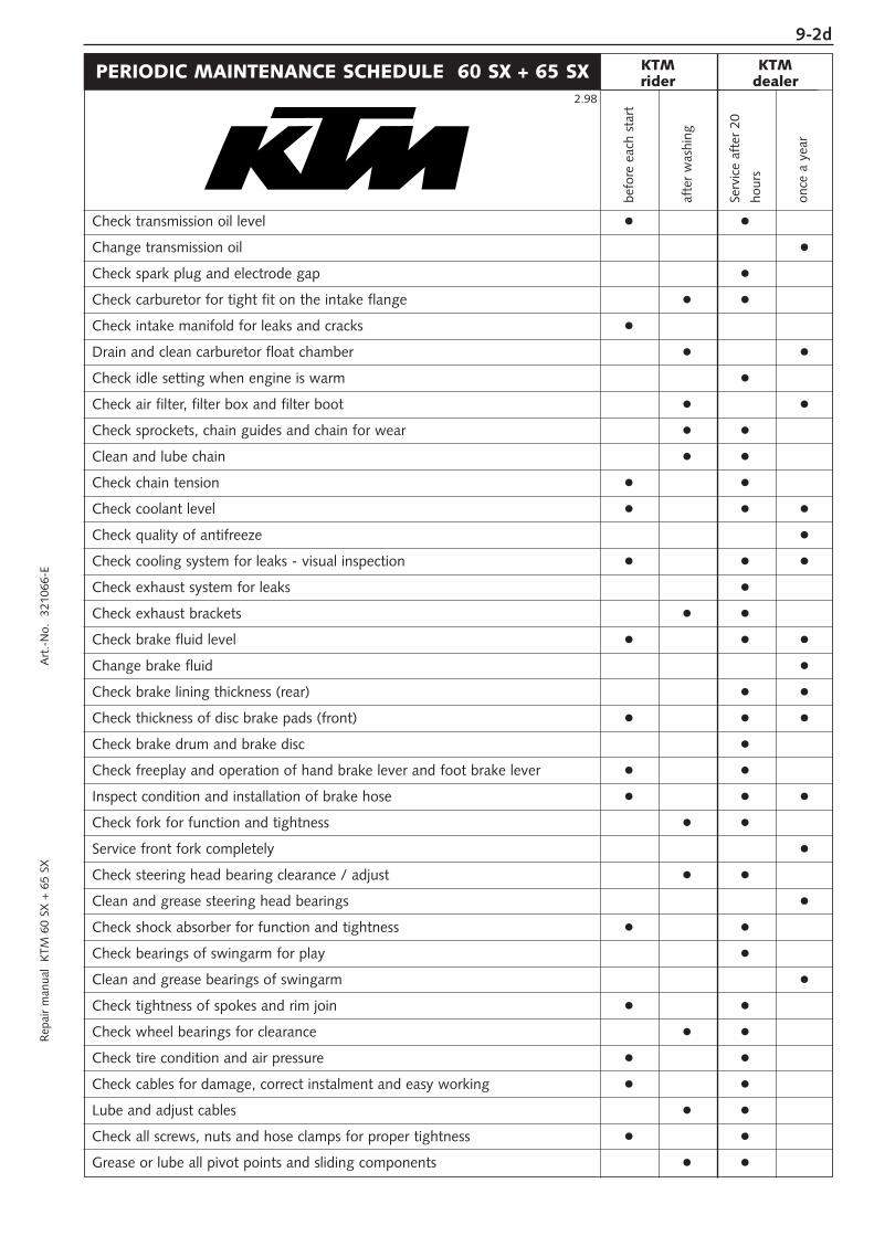
9-2dR
epai
r m
anua
l K
TM 6
0 SX
+ 6
5 SX
A
rt.-
No.
32
1066
-E
PERIODIC MAINTENANCE SCHEDULE 60 SX + 65 SX
Check transmission oil level
Change transmission oil
Check spark plug and electrode gap
Check carburetor for tight fit on the intake flange
Check intake manifold for leaks and cracks
Drain and clean carburetor float chamber
Check idle setting when engine is warm
Check air filter, filter box and filter boot
Check sprockets, chain guides and chain for wear
Clean and lube chain
Check chain tension
Check coolant level
Check quality of antifreeze
Check cooling system for leaks - visual inspection
Check exhaust system for leaks
Check exhaust brackets
Check brake fluid level
Change brake fluid
Check brake lining thickness (rear)
Check thickness of disc brake pads (front)
Check brake drum and brake disc
Check freeplay and operation of hand brake lever and foot brake lever
Inspect condition and installation of brake hose
Check fork for function and tightness
Service front fork completely
Check steering head bearing clearance / adjust
Clean and grease steering head bearings
Check shock absorber for function and tightness
Check bearings of swingarm for play
Clean and grease bearings of swingarm
Check tightness of spokes and rim join
Check wheel bearings for clearance
Check tire condition and air pressure
Check cables for damage, correct instalment and easy working
Lube and adjust cables
Check all screws, nuts and hose clamps for proper tightness
Grease or lube all pivot points and sliding components
befo
re e
ach
star
t
afte
r w
ashi
ng
Serv
ice
afte
r 20
hour
s
once
a y
ear
KTMrider
KTM dealer
2.98
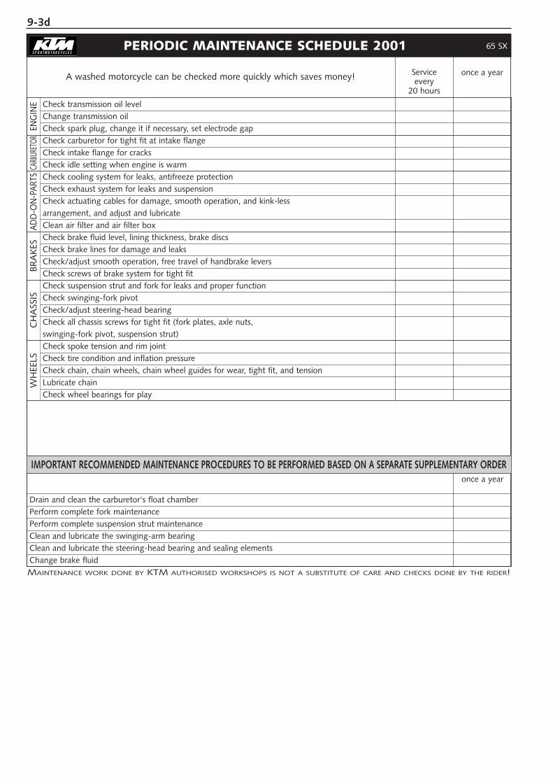
9-3d
PERIODIC MAINTENANCE SCHEDULE 2001
Serviceevery
20 hours
once a year
MAINTENANCE WORK DONE BY KTM AUTHORISED WORKSHOPS IS NOT A SUBSTITUTE OF CARE AND CHECKS DONE BY THE RIDER!
A washed motorcycle can be checked more quickly which saves money!
Check transmission oil level
Change transmission oil
Check spark plug, change it if necessary, set electrode gap
Check carburetor for tight fit at intake flange
Check intake flange for cracks
Check idle setting when engine is warm
Check cooling system for leaks, antifreeze protection
Check exhaust system for leaks and suspension
Check actuating cables for damage, smooth operation, and kink-less
arrangement, and adjust and lubricateClean air filter and air filter box
Check brake fluid level, lining thickness, brake discs
Check brake lines for damage and leaks
Check/adjust smooth operation, free travel of handbrake levers
Check screws of brake system for tight fit
Check suspension strut and fork for leaks and proper function
Check swinging-fork pivot
Check/adjust steering-head bearing
Check all chassis screws for tight fit (fork plates, axle nuts,
swinging-fork pivot, suspension strut)Check spoke tension and rim joint
Check tire condition and inflation pressure
Check chain, chain wheels, chain wheel guides for wear, tight fit, and tension
Lubricate chain
Check wheel bearings for play
IMPORTANT RECOMMENDED MAINTENANCE PROCEDURES TO BE PERFORMED BASED ON A SEPARATE SUPPLEMENTARY ORDER
Drain and clean the carburetor's float chamber
Perform complete fork maintenance
Perform complete suspension strut maintenance
Clean and lubricate the swinging-arm bearing
Clean and lubricate the steering-head bearing and sealing elements
Change brake fluid
WH
EELS
CH
ASS
ISBR
AK
ESAD
D-O
N-P
ARTS
ENG
INE
65 SX
once a year
CARB
URET
OR
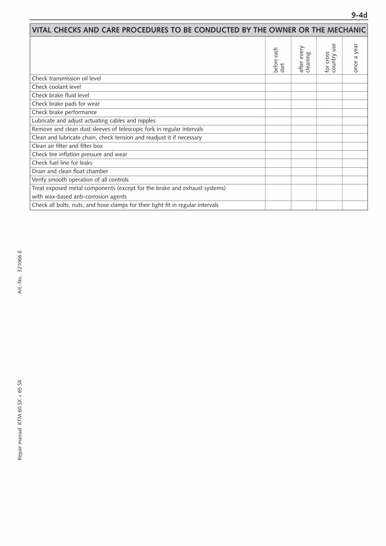
9-4dR
epai
r m
anua
l K
TM 6
0 SX
+ 6
5 SX
A
rt.-
No.
32
1066
-E
VITAL CHECKS AND CARE PROCEDURES TO BE CONDUCTED BY THE OWNER OR THE MECHANIC
Check transmission oil level
Check coolant level
Check brake fluid level
Check brake pads for wear
Check brake performance
Lubricate and adjust actuating cables and nipples
Remove and clean dust sleeves of telescopic fork in regular intervals
Clean and lubricate chain, check tension and readjust it if necessary
Clean air filter and filter box
Check tire inflation pressure and wear
Check fuel line for leaks
Drain and clean float chamber
Verify smooth operation of all controls
Treat exposed metal components (except for the brake and exhaust systems)
with wax-based anti-corrosion agentsCheck all bolts, nuts, and hose clamps for their tight fit in regular intervals
for
cros
sco
untr
y us
e
once
a y
ear
afte
r ev
ery
clea
ning
befo
re e
ach
star
t
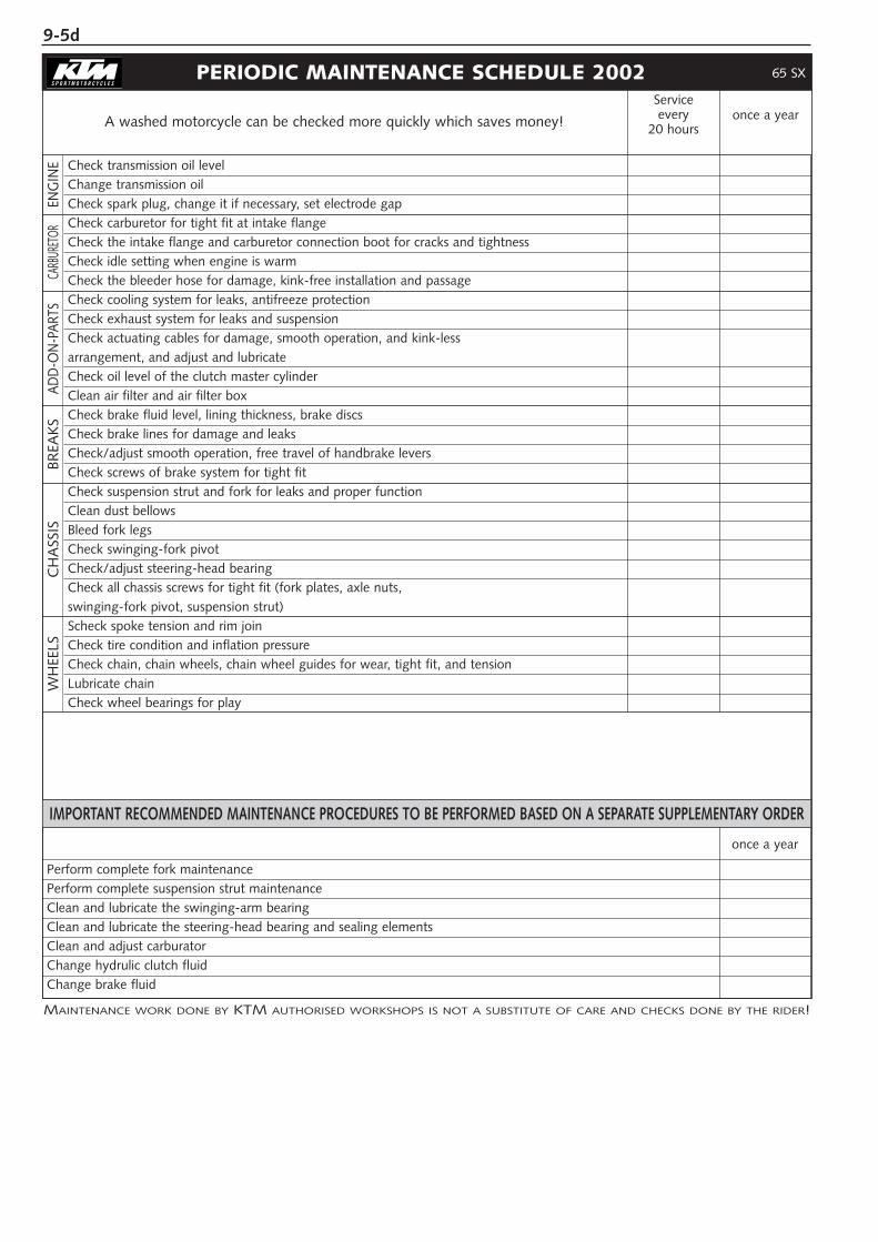
9-5d
PERIODIC MAINTENANCE SCHEDULE 2002Serviceevery
20 hoursonce a year
MAINTENANCE WORK DONE BY KTM AUTHORISED WORKSHOPS IS NOT A SUBSTITUTE OF CARE AND CHECKS DONE BY THE RIDER!
A washed motorcycle can be checked more quickly which saves money!
Check transmission oil level
Change transmission oil
Check spark plug, change it if necessary, set electrode gap
Check carburetor for tight fit at intake flange
Check the intake flange and carburetor connection boot for cracks and tightness
Check idle setting when engine is warm
Check the bleeder hose for damage, kink-free installation and passage
Check cooling system for leaks, antifreeze protection
Check exhaust system for leaks and suspension
Check actuating cables for damage, smooth operation, and kink-less
arrangement, and adjust and lubricateCheck oil level of the clutch master cylinder
Clean air filter and air filter box
Check brake fluid level, lining thickness, brake discs
Check brake lines for damage and leaks
Check/adjust smooth operation, free travel of handbrake levers
Check screws of brake system for tight fit
Check suspension strut and fork for leaks and proper function
Clean dust bellows
Bleed fork legs
Check swinging-fork pivot
Check/adjust steering-head bearing
Check all chassis screws for tight fit (fork plates, axle nuts,
swinging-fork pivot, suspension strut)Scheck spoke tension and rim join
Check tire condition and inflation pressure
Check chain, chain wheels, chain wheel guides for wear, tight fit, and tension
Lubricate chain
Check wheel bearings for play
IMPORTANT RECOMMENDED MAINTENANCE PROCEDURES TO BE PERFORMED BASED ON A SEPARATE SUPPLEMENTARY ORDER
Perform complete fork maintenance
Perform complete suspension strut maintenance
Clean and lubricate the swinging-arm bearing
Clean and lubricate the steering-head bearing and sealing elements
Clean and adjust carburator
Change hydrulic clutch fluid
Change brake fluid
WH
EELS
CH
ASS
ISBR
EAK
SAD
D-O
N-P
ARTS
ENG
INE
65 SX
once a year
CARB
URET
OR
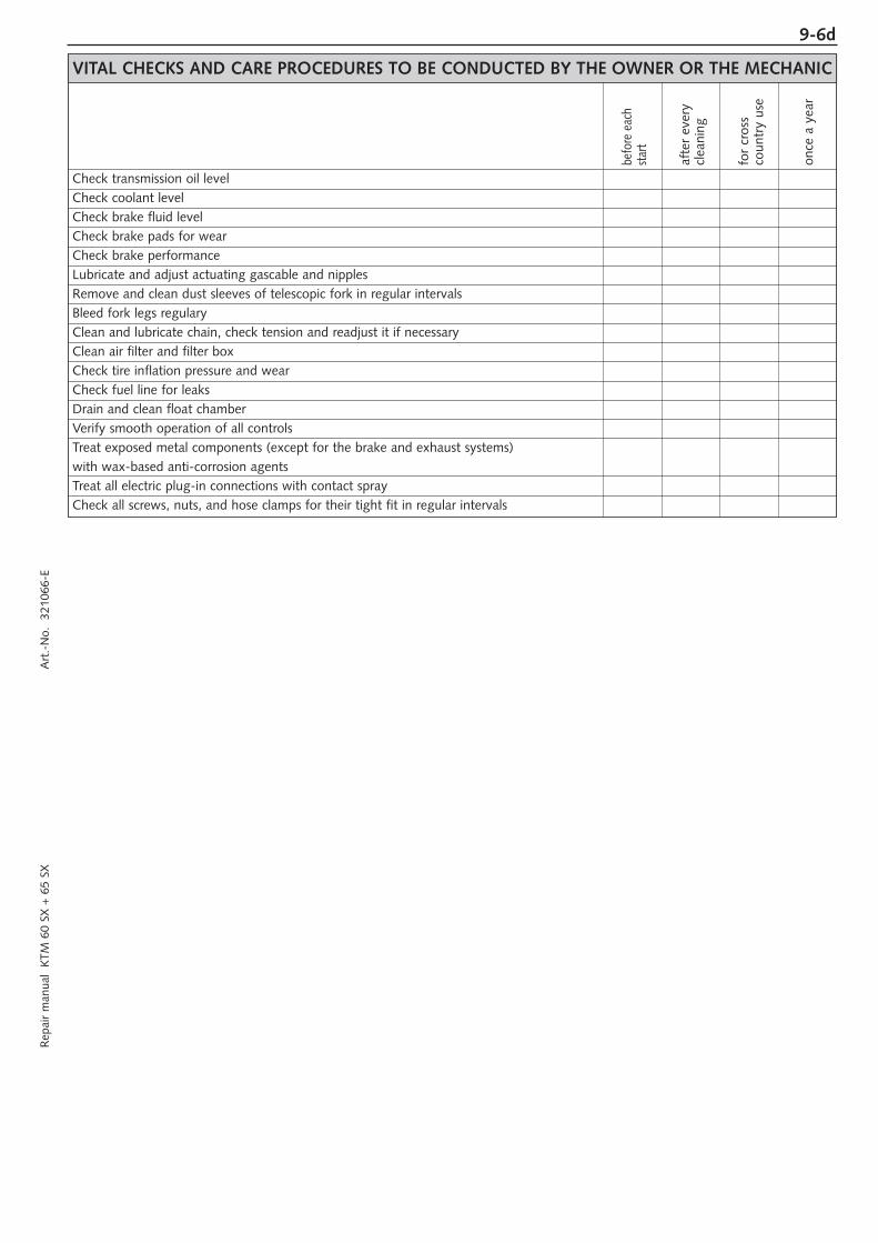
9-6dR
epai
r m
anua
l K
TM 6
0 SX
+ 6
5 SX
A
rt.-
No.
32
1066
-E
VITAL CHECKS AND CARE PROCEDURES TO BE CONDUCTED BY THE OWNER OR THE MECHANIC
Check transmission oil level
Check coolant level
Check brake fluid level
Check brake pads for wear
Check brake performance
Lubricate and adjust actuating gascable and nipples
Remove and clean dust sleeves of telescopic fork in regular intervals
Bleed fork legs regulary
Clean and lubricate chain, check tension and readjust it if necessary
Clean air filter and filter box
Check tire inflation pressure and wear
Check fuel line for leaks
Drain and clean float chamber
Verify smooth operation of all controls
Treat exposed metal components (except for the brake and exhaust systems)
with wax-based anti-corrosion agentsTreat all electric plug-in connections with contact spray
Check all screws, nuts, and hose clamps for their tight fit in regular intervals
for
cros
sco
untr
y us
e
once
a y
ear
afte
r ev
ery
clea
ning
befo
re e
ach
star
t

9-7d
PERIODIC MAINTENANCE SCHEDULE 2003Serviceevery
20 hoursonce a year
MAINTENANCE WORK DONE BY KTM AUTHORISED WORKSHOPS IS NOT A SUBSTITUTE FOR CARE AND CHECKS DONE BY THE RIDER!
A clean motorcycle can be checked more quickly which saves money!
Check transmission oil level
Change transmission oil
Check spark plug, change it if necessary, set electrode gap
Check carburetor for a tight fit at intake flange
Check the intake flange and carburetor connection boot for cracks and tightness
Check idle setting when engine is warm
Check the bleeder hose for damage, kinkless installation and passage
Check cooling system for leaks, antifreeze protection
Check exhaust system for leaks and suspension
Check actuating cables for damage, smooth operation, and kinkless
arrangement, and adjust and lubricateCheck oil level of the clutch master cylinder
Clean air filter and air filter box
Check brake fluid level, lining thickness, brake discs
Check brake lines for damage and leaks
Check functiuon/adjust smooth operation, free travel of handbrake levers
Check screws of brake system for a tight fit
Check suspension strut and fork for leaks and a proper function
Clean dust bellows
Bleed fork legs
Check swinging-fork pivot
Check/adjust steering-head bearing
Check all chassis screws for a tight fit (fork plates, axle nuts,
swinging-fork pivot, suspension strut)Check spoke tension and rim joint
Check tire condition and inflation pressure
Check chain, chain wheels, chain wheel, chain joint guides for wear, tight fit, and tension
Lubricate chain
Check wheel bearings for play
IMPORTANT RECOMMENDED MAINTENANCE PROCEDURES TO BE PERFORMED BASED ON A SEPARATE SUPPLEMENTARY ORDER
Perform complete fork maintenance
Perform complete suspension strut maintenance
Clean and lubricate the swinging-arm bearing
Clean and lubricate the steering-head bearing and sealing elements
Clean and adjust carburator
Change hydrulic clutch fluid
Change brake fluid
WH
EELS
CH
ASS
ISBR
EAK
SAD
D-O
N-P
ARTS
ENG
INE
65 SX
once a year
CARB
URET
OR
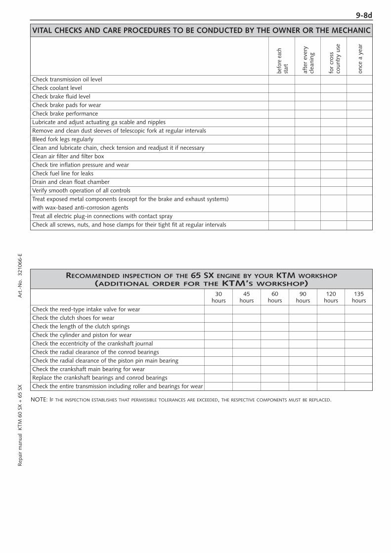
9-8dR
epai
r m
anua
l K
TM 6
0 SX
+ 6
5 SX
A
rt.-
No.
32
1066
-E
VITAL CHECKS AND CARE PROCEDURES TO BE CONDUCTED BY THE OWNER OR THE MECHANIC
Check transmission oil level
Check coolant level
Check brake fluid level
Check brake pads for wear
Check brake performance
Lubricate and adjust actuating ga scable and nipples
Remove and clean dust sleeves of telescopic fork at regular intervals
Bleed fork legs regularly
Clean and lubricate chain, check tension and readjust it if necessary
Clean air filter and filter box
Check tire inflation pressure and wear
Check fuel line for leaks
Drain and clean float chamber
Verify smooth operation of all controls
Treat exposed metal components (except for the brake and exhaust systems)
with wax-based anti-corrosion agentsTreat all electric plug-in connections with contact spray
Check all screws, nuts, and hose clamps for their tight fit at regular intervals
for
cros
sco
untr
y us
e
once
a y
ear
afte
r ev
ery
clea
ning
befo
re e
ach
star
t
RECOMMENDED INSPECTION OF THE 65 SX ENGINE BY YOUR KTM WORKSHOP(ADDITIONAL ORDER FOR THE KTM’S WORKSHOP)
Check the reed-type intake valve for wear
Check the clutch shoes for wear
Check the length of the clutch springs
Check the cylinder and piston for wear
Check the eccentricity of the crankshaft journal
Check the radial clearance of the conrod bearings
Check the radial clearance of the piston pin main bearing
Check the crankshaft main bearing for wear
Replace the crankshaft bearings and conrod bearings
Check the entire transmission including roller and bearings for wear
30hours
45hours
60hours
90hours
120hours
135hours
NOTE: IF THE INSPECTION ESTABLISHES THAT PERMISSIBLE TOLERANCES ARE EXCEEDED, THE RESPECTIVE COMPONENTS MUST BE REPLACED.