Embed Size (px)
Citation preview
Part Number 9291505 10/16
Versa Drawer™Refrigeration Units
Original InstructionsService ManualEnglish
Safety Notices
nWarningRead this manual thoroughly before operating, installing or performing maintenance on the equipment. Failure to follow instructions in this manual can cause property damage, injury or death.
DANGERDo not install or operate equipment that has been misused, abused, neglected, damaged, or altered/modified from that of original manufactured specifications.
DANGERKeep power cord AWAY from HEATED surfaces. DO NOT immerse power cord or plug in water. DO NOT let power cord hang over edge of table or counter.
DANGERAll utility connections and fixtures must be maintained in accordance with Local and national codes.
DANGERDo not lift the condensing unit by the refrigerant tubing or other components. These features will not support the condensing unit weight. Injury and unit damage may occur!
nWarningAuthorized Service Representatives are obligated to follow industry standard safety procedures, including, but not limited to, local/national regulations for disconnection / lock out / tag out procedures for all utilities including electric, gas, water and steam.
nWarningDo not store or use gasoline or other flammable vapors or liquids in the vicinity of this or any other appliance. Never use flammable oil soaked cloths or combustible cleaning solutions, for cleaning.
nWarningThis product contains chemicals known to the State of California to cause cancer and/or birth defects or other reproductive harm. Operation, installation, and servicing of this product could expose you to airborne particles of glasswool or ceramic fibers, crystalline silica, and/or carbon monoxide. Inhalation of airborne particles of glasswool or ceramic fibers is known to the State of California to cause cancer. Inhalation of carbon monoxide is known to the State of California to cause birth defects or other reproductive harm.
nWarningDo not use electrical appliances or accessories other than those supplied by the manufacturer.
nWarningUse caution when handling metal surface edges of all equipment.
nWarningThis appliance is not intended for use by persons (including children) with reduced physical, sensory or mental capabilities, or lack of experience and knowledge, unless they have been given supervision concerning use of the appliance by a person responsible for their safety. Do not allow children to play with this appliance.
nWarningDO NOT touch refrigeration lines inside units; some may exceed temperatures of 200°F (93.3°C).
,CautionWhen adding any item verify the location of the refrigeration lines on wrapped rail units. A refrigeration leak in a rail may be irreparable or extremely difficult and costly to repair.
NoteProper installation, care and maintenance are essential for maximum performance and trouble-free operation of your equipment. Visit our website www.mtwkitchencare.com for manual updates, translations, or contact information for service agents in your area.

Table of Contents
Part Number 9291505 10/16 3
Section 1General Information
Model Numbers .................................................................................................................. 5Serial Number Location ..................................................................................................... 5Warranty Information ........................................................................................................ 5Regulatory Certifications .................................................................................................. 5
Section 2Installation
Location .............................................................................................................................. 7Weight of Equipment ......................................................................................................... 8Clearance Requirements .................................................................................................... 8Dimensions ......................................................................................................................... 8Electrical Service ................................................................................................................ 9
Voltage .......................................................................................................................................................9Rated Amperages, Horsepower, Voltage & Power Cord Chart ...............................................9
Drain Connections ............................................................................................................10Refrigeration ....................................................................................................................10Casters Or Legs .................................................................................................................10
Leg Leveling .......................................................................................................................................... 10Leg Removal And Replacement ..................................................................................................... 10Caster Removal And Replacement................................................................................................ 11
Section 3Operation
General ..............................................................................................................................13Refrigeration System .......................................................................................................14Control Panel ....................................................................................................................14
Section 4Maintenance
Cleaning and Sanitizing Procedures ...............................................................................17General .................................................................................................................................................... 17Interior Cleaning .................................................................................................................................. 18Exterior Cleaning ................................................................................................................................. 18Casters ..................................................................................................................................................... 18Drawer Maintenance .......................................................................................................................... 19Drain ......................................................................................................................................................... 19Cleaning the Condenser Coil .......................................................................................................... 19Field Installation .................................................................................................................................. 19
Section 5Controls
Changing Drawer Modes .................................................................................................21Manual Defrost .................................................................................................................21Program Menu ..................................................................................................................22Set Points ..........................................................................................................................22Configuration ...................................................................................................................22Diagnostics .......................................................................................................................23Time and Date ...................................................................................................................23Software Versions ............................................................................................................23
4 Part Number 9291505 10/16
Table of Contents (continued)
Section 6Troubleshooting
Alarm Code Chart .............................................................................................................25Sequence Of Operation ...................................................................................................26
Freezer ..................................................................................................................................................... 26Refrigerator ......................................................................................................................26
Chill ........................................................................................................................................................... 26Thaw ..................................................................................................................................26
Defrost ..................................................................................................................................................... 26Troubleshooting Chart ....................................................................................................27Component Troubleshooting ..........................................................................................30Defaults and Ranges ........................................................................................................32
Section 7Component Removal And Replacement
Front Louvered Panel .......................................................................................................33Louvered Access End Panel .............................................................................................33Rear Panel .........................................................................................................................33Drawer Assembly .............................................................................................................34Return Air Baffle ...............................................................................................................35Evaporator Fans ...............................................................................................................35Drawer Switch ...................................................................................................................36Evaporator Coil Assembly Cover .....................................................................................36Evaporator Coil Assembly ...............................................................................................37Probes Defrost ..................................................................................................................37Probes Cabinet .................................................................................................................38Expansion Valve ...............................................................................................................38Condenser Fan Blade .......................................................................................................39Condenser Fan Motor.......................................................................................................39Condenser Coil .................................................................................................................40Compressor .......................................................................................................................40Accumulator/Receiver ......................................................................................................41Filter Dryer ........................................................................................................................41Solenoid Valves ................................................................................................................41Pressure Transducer .........................................................................................................42Display Control Board - From the Rear of the Unit ..............................................................................................42Display Control Board - From the Front of the Unit .............................................................................................43Electric Input/Output (I/O) Control Board ......................................................................43
Section 8Diagrams
Refrigeration Schematic ..................................................................................................45Versa Drawer Electric Input/Output (I/O) Control Board Connector Map ...................46Versa Drawer 4-Drawer Wiring Diagram (1 of 2) ............................................................47Versa Drawer 4-Drawer Wiring Diagram (2 of 2) ............................................................48Versa Drawer 2-Drawer Wiring Diagram (1 of 2) ............................................................49Versa Drawer 2-Drawer Wiring Diagram (2 of 2) ............................................................50
Part Number 9291505 10/16 5
Model NumbersNOTE: This manual covers standard units only. If you have a custom unit, consult the technical service department.
Model Model DescriptionF17VD84 115V/60Hz Component Crafted
F17VD84-CE 230-240V/50Hz Component CraftedF18VD50 115V/60Hz Component Crafted
F18VD50-CE 230-240V/50Hz Component CraftedF18VD82 115V/60Hz Component Crafted
F18VD82-CE 230-240V/50Hz Component CraftedF2984VDR 115V/60Hz Freestanding
F2984VDR-CE 230-240V/50Hz FreestandingF2984VDL 115V/60Hz Freestanding
F2984VDL-CE 230-240V/50Hz Freestanding18650VDR 115V/60Hz Freestanding
18650VDR-CE 230-240V/50Hz Freestanding18650VDL 115V/60Hz Freestanding
18650VDL-CE 230-240V/50Hz Freestanding18682VDR 115V/60Hz Freestanding
18682VDR-CE 230-240V/50Hz Freestanding18682VDL 115V/60Hz Freestanding
18682VDL-CE 230-240V/50Hz Freestanding
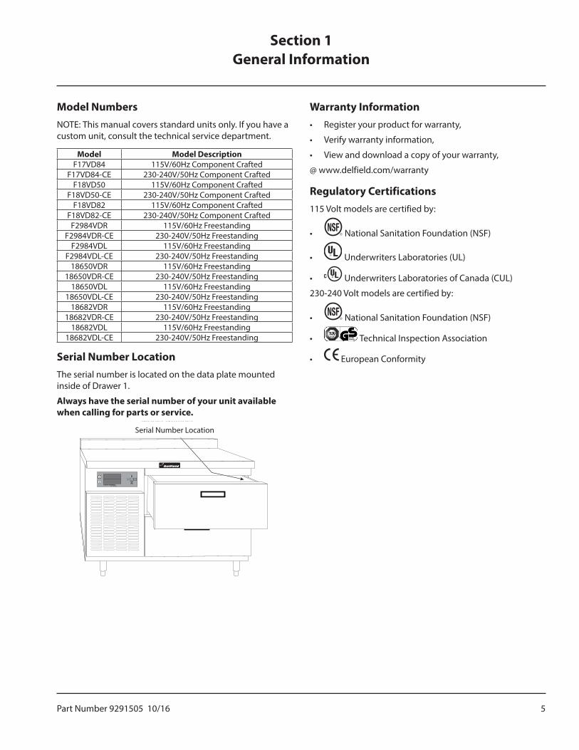
Serial Number LocationThe serial number is located on the data plate mounted inside of Drawer 1.
Always have the serial number of your unit available when calling for parts or service.
Serial Number Location
Warranty Information• Register your product for warranty,
• Verify warranty information,
• View and download a copy of your warranty,
@ www.delfield.com/warranty
Regulatory Certifications115 Volt models are certified by:
• National Sanitation Foundation (NSF)
• Underwriters Laboratories (UL)
• Underwriters Laboratories of Canada (CUL)
230-240 Volt models are certified by:
• National Sanitation Foundation (NSF)
• Technical Inspection Association
• European Conformity
Section 1General Information
6 Part Number 9291505 10/16
General Information Section 1
THIS PAGE INTENTIONALLY LEFT BLANK
Part Number 9291505 10/16 7
DANGERInstallation must comply with all applicable fire and health codes in your jurisdiction.
DANGERUse appropriate safety equipment during installation and servicing
nWarningRemove all removable panels before lifting and installing.
nWarningDo not damage the refrigeration circuit when installing, maintaining or servicing the unit.
Location
nWarningThis equipment must be positioned so that the plug is accessible unless other means for disconnection from the power supply (e.g., circuit breaker or disconnect switch) is provided.
nWarningAdequate means must be provided to limit the movement of this appliance without depending on or transmitting stress to the electrical conduit or gas lines.
nWarningTo avoid instability the installation area must be capable of supporting the combined weight of the equipment and product. Additionally the equipment must be level side to side and front to back.
nWarningThis equipment is intended for indoor use only. Do not install or operate this equipment in outdoor areas.
,CautionDo not position the air intake vent near steam or heat exhaust of another appliance. Direct exposure to excessive amounts of steam in machine compartment will result in control board failure.
The location selected for the equipment must meet the following criteria. If any of these criteria are not met, select another location.
• Units are intended for indoor use only.
• The location MUST be level, stable and capable of supporting the weight of the equipment.
• The location MUST be free from and clear of combustible materials.
• Equipment MUST be level both front to back and side to side.
• Position the equipment so it will not tip or slide.
• Front casters MUST be locked once positioned.
• Recommended air temperature is 41° - 86°F (5° - 30°C).
• Proper air supply for ventilation is REQUIRED AND CRITICAL for safe and efficient operation. Refer to Clearance Requirements chart on page 8.
• Do not obstruct the flow of ventilation air. Make sure the air vents of the equipment are not blocked.
• Do not install the equipment directly over a drain. Steam rising up out of the drain will adversely affect operation, air circulation, and damage electrical / electronic components.
Section 2Installation
8 Part Number 9291505 10/16
Installation Section 2
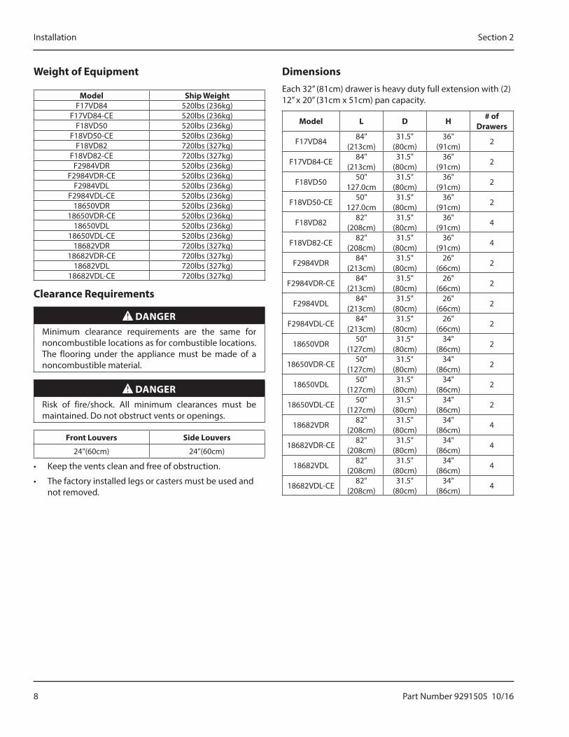
Weight of Equipment
Model Ship WeightF17VD84 520lbs (236kg)
F17VD84-CE 520lbs (236kg)F18VD50 520lbs (236kg)
F18VD50-CE 520lbs (236kg)F18VD82 720lbs (327kg)
F18VD82-CE 720lbs (327kg)F2984VDR 520lbs (236kg)
F2984VDR-CE 520lbs (236kg)F2984VDL 520lbs (236kg)
F2984VDL-CE 520lbs (236kg)18650VDR 520lbs (236kg)
18650VDR-CE 520lbs (236kg)18650VDL 520lbs (236kg)
18650VDL-CE 520lbs (236kg)18682VDR 720lbs (327kg)
18682VDR-CE 720lbs (327kg)18682VDL 720lbs (327kg)
18682VDL-CE 720lbs (327kg)
Clearance Requirements
DANGERMinimum clearance requirements are the same for noncombustible locations as for combustible locations. The flooring under the appliance must be made of a noncombustible material.
DANGERRisk of fire/shock. All minimum clearances must be maintained. Do not obstruct vents or openings.
Front Louvers Side Louvers
24”(60cm) 24”(60cm)
• Keep the vents clean and free of obstruction.
• The factory installed legs or casters must be used and not removed.
DimensionsEach 32” (81cm) drawer is heavy duty full extension with (2) 12” x 20” (31cm x 51cm) pan capacity.
Model L D H # of Drawers
F17VD8484"
(213cm)31.5"
(80cm)36"
(91cm)2
F17VD84-CE84"
(213cm)31.5"
(80cm)36"
(91cm)2
F18VD5050"
127.0cm31.5"
(80cm)36"
(91cm)2
F18VD50-CE50"
127.0cm31.5"
(80cm)36"
(91cm)2
F18VD8282"
(208cm)31.5"
(80cm)36"
(91cm)4
F18VD82-CE82"
(208cm)31.5"
(80cm)36"
(91cm)4
F2984VDR84"
(213cm)31.5"
(80cm)26"
(66cm)2
F2984VDR-CE84"
(213cm)31.5"
(80cm)26"
(66cm)2
F2984VDL84"
(213cm)31.5"
(80cm)26"
(66cm)2
F2984VDL-CE84"
(213cm)31.5"
(80cm)26"
(66cm)2
18650VDR50"
(127cm)31.5"
(80cm)34"
(86cm)2
18650VDR-CE50"
(127cm)31.5"
(80cm)34"
(86cm)2
18650VDL50"
(127cm)31.5"
(80cm)34"
(86cm)2
18650VDL-CE50"
(127cm)31.5"
(80cm)34"
(86cm)2
18682VDR82"
(208cm)31.5"
(80cm)34"
(86cm)4
18682VDR-CE82"
(208cm)31.5"
(80cm)34"
(86cm)4
18682VDL82"
(208cm)31.5"
(80cm)34"
(86cm)4
18682VDL-CE82"
(208cm)31.5"
(80cm)34"
(86cm)4
Part Number 9291505 10/16 9
Section 2 Installation
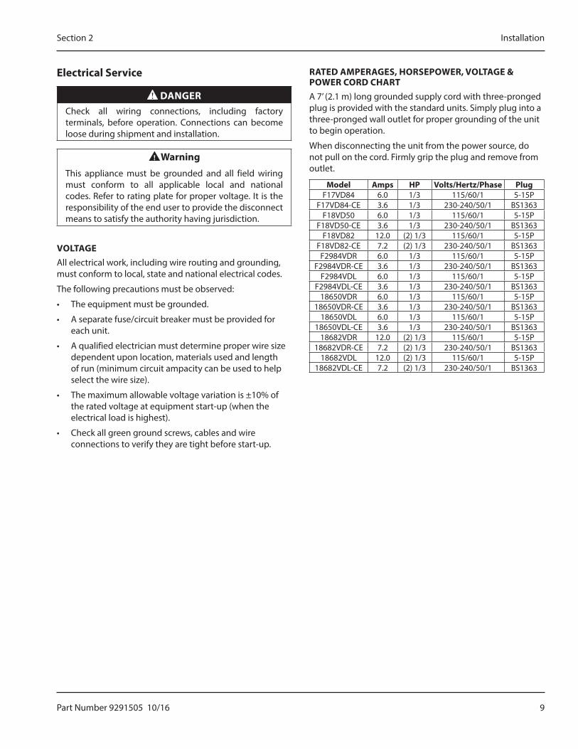
Electrical Service
DANGERCheck all wiring connections, including factory terminals, before operation. Connections can become loose during shipment and installation.
nWarningThis appliance must be grounded and all field wiring must conform to all applicable local and national codes. Refer to rating plate for proper voltage. It is the responsibility of the end user to provide the disconnect means to satisfy the authority having jurisdiction.
VOLTAGEAll electrical work, including wire routing and grounding, must conform to local, state and national electrical codes.
The following precautions must be observed:
• The equipment must be grounded.
• A separate fuse/circuit breaker must be provided for each unit.
• A qualified electrician must determine proper wire size dependent upon location, materials used and length of run (minimum circuit ampacity can be used to help select the wire size).
• The maximum allowable voltage variation is ±10% of the rated voltage at equipment start-up (when the electrical load is highest).
• Check all green ground screws, cables and wire connections to verify they are tight before start-up.
RATED AMPERAGES, HORSEPOWER, VOLTAGE & POWER CORD CHARTA 7’ (2.1 m) long grounded supply cord with three-pronged plug is provided with the standard units. Simply plug into a three-pronged wall outlet for proper grounding of the unit to begin operation.
When disconnecting the unit from the power source, do not pull on the cord. Firmly grip the plug and remove from outlet.
Model Amps HP Volts/Hertz/Phase PlugF17VD84 6.0 1/3 115/60/1 5-15P
F17VD84-CE 3.6 1/3 230-240/50/1 BS1363F18VD50 6.0 1/3 115/60/1 5-15P
F18VD50-CE 3.6 1/3 230-240/50/1 BS1363F18VD82 12.0 (2) 1/3 115/60/1 5-15P
F18VD82-CE 7.2 (2) 1/3 230-240/50/1 BS1363F2984VDR 6.0 1/3 115/60/1 5-15P
F2984VDR-CE 3.6 1/3 230-240/50/1 BS1363F2984VDL 6.0 1/3 115/60/1 5-15P
F2984VDL-CE 3.6 1/3 230-240/50/1 BS136318650VDR 6.0 1/3 115/60/1 5-15P
18650VDR-CE 3.6 1/3 230-240/50/1 BS136318650VDL 6.0 1/3 115/60/1 5-15P
18650VDL-CE 3.6 1/3 230-240/50/1 BS136318682VDR 12.0 (2) 1/3 115/60/1 5-15P
18682VDR-CE 7.2 (2) 1/3 230-240/50/1 BS136318682VDL 12.0 (2) 1/3 115/60/1 5-15P
18682VDL-CE 7.2 (2) 1/3 230-240/50/1 BS1363
10 Part Number 9291505 10/16
Installation Section 2
Drain Connections
nWarningIf a refrigerated base does not have a condensate evaporator supplied, you must connect the condensate line to a suitable drain. Otherwise, water will collect on the floor, causing a potentially hazardous situation.
nWarningMoisture collecting from improper drainage can create a slippery surface on the floor and a hazard to employees. It is the owner’s responsibility to provide a container or outlet for drainage.
All models are standard with a condensate evaporator pan.
RefrigerationThe refrigeration system uses HFC-404A refrigerant.
If your freezer seems to vibrate excessively when the compressor is running, loosen (but do not remove) the bolts on the compressor. Semi hermetic models should be loosened before operating.
Model Compressor Position Ref. Charge
F17VD84 Left 30 oz (850.5g)F17VD84-CE Left 30 oz (850.5g)
F18VD50 Left 30 oz (850.5g)F18VD50-CE Left 30 oz (850.5g)
F18VD82 Left (2) 30 oz (850.5g)F18VD82-CE Left (2) 30 oz (850.5g)
F2984VDR Right 30 oz (850.5g)F2984VDR-CE Right 30 oz (850.5g)
F2984VDL Left 30 oz (850.5g)F2984VDL-CE Left 30 oz (850.5g)
18650VDR Right 30 oz (850.5g)18650VDR-CE Right 30 oz (850.5g)
18650VDL Left 30 oz (850.5g)18650VDL-CE Left 30 oz (850.5g)
18682VDR Right (2) 30 oz (850.5g)18682VDR-CE Right (2) 30 oz (850.5g)
18682VDL Left (2) 30 oz (850.5g)18682VDL-CE Left (2) 30 oz (850.5g)
Casters Or Legs
DANGERLegs or casters must be installed and the legs or casters must be screwed in completely to prevent bending. When casters are installed the mass of this unit will allow it to move uncontrolled on an inclined surface. These units must be tethered/secured to comply with all applicable codes.
nWarningUse a jack to lift the refrigeration unit off the ground just far enough to remove the leg/caster. Place blocking underneath the unit. Do not work underneath a raised unit without proper blocking. Do not lift the unit more than necessary to remove the leg/caster. Lifting the unit too far can make the unit unstable.
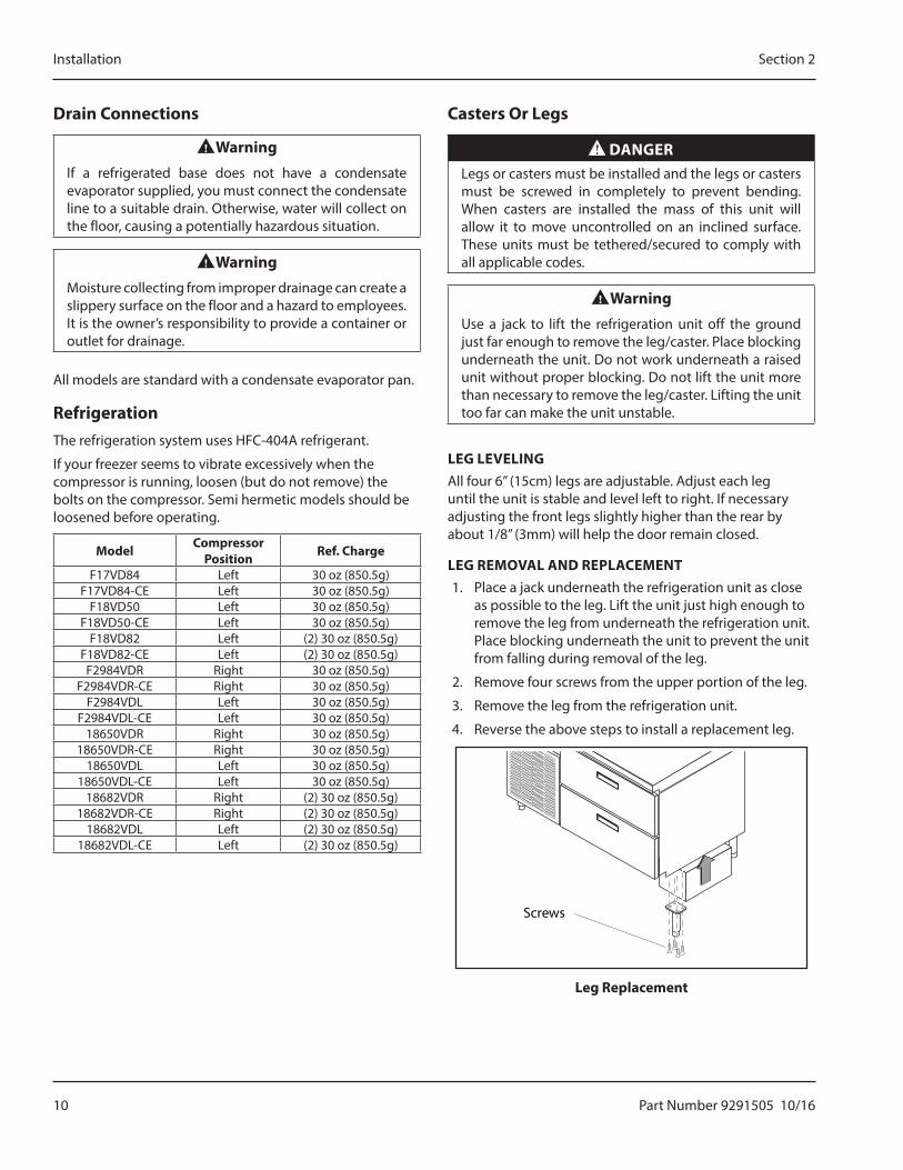
LEG LEVELINGAll four 6” (15cm) legs are adjustable. Adjust each leg until the unit is stable and level left to right. If necessary adjusting the front legs slightly higher than the rear by about 1/8” (3mm) will help the door remain closed.
LEG REMOVAL AND REPLACEMENT1. Place a jack underneath the refrigeration unit as close
as possible to the leg. Lift the unit just high enough to remove the leg from underneath the refrigeration unit. Place blocking underneath the unit to prevent the unit from falling during removal of the leg.
2. Remove four screws from the upper portion of the leg.
3. Remove the leg from the refrigeration unit.
4. Reverse the above steps to install a replacement leg.
Screws
Leg Replacement
Part Number 9291505 10/16 11
Section 2 Installation
CASTER REMOVAL AND REPLACEMENT
nWarningThe unit must be installed in a stable condition with the front wheels locked. Locking the front casters after installation is the owner’s and operator’s responsibility.
,CautionAfter installing casters, the unit must stand upright for twenty-four (24) hours before being powered up to assure oil return to the compressor sump.
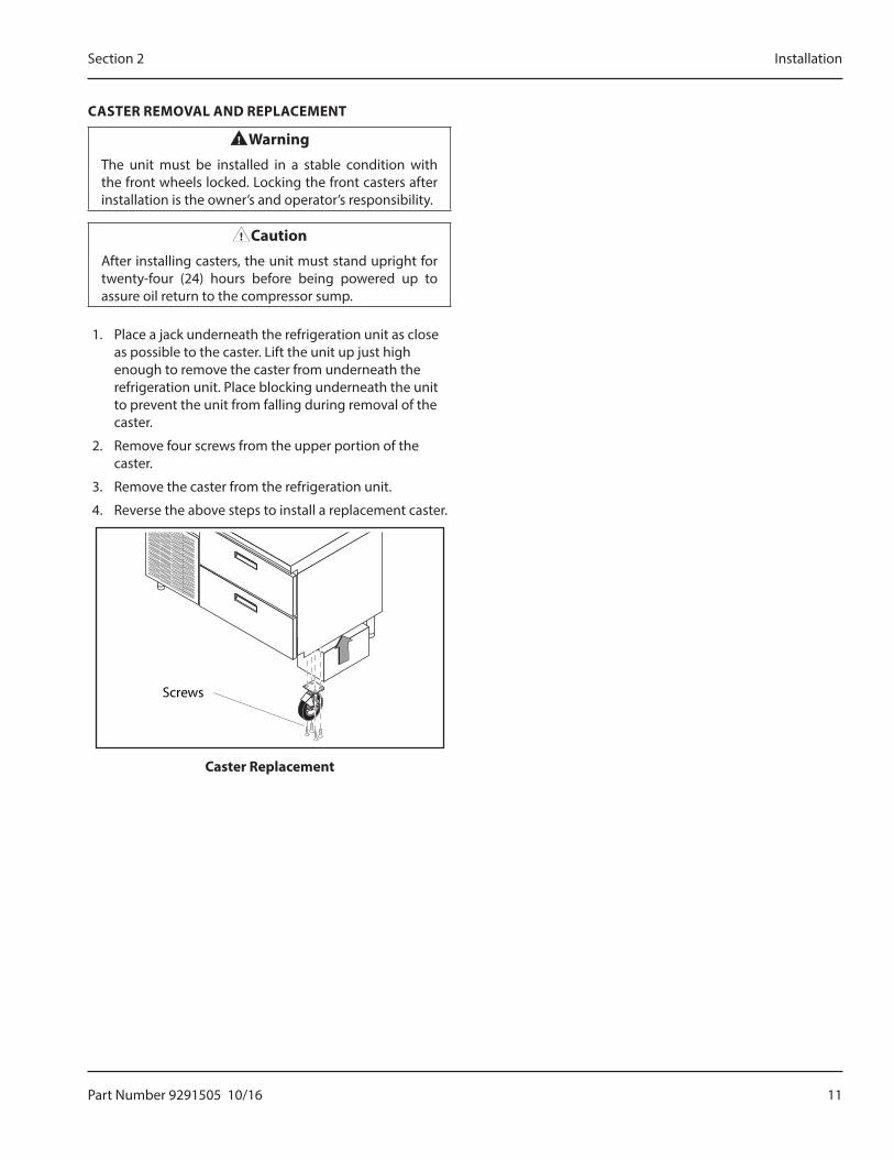
1. Place a jack underneath the refrigeration unit as close as possible to the caster. Lift the unit up just high enough to remove the caster from underneath the refrigeration unit. Place blocking underneath the unit to prevent the unit from falling during removal of the caster.
2. Remove four screws from the upper portion of the caster.
3. Remove the caster from the refrigeration unit.
4. Reverse the above steps to install a replacement caster.
Screws
Caster Replacement
12 Part Number 9291505 10/16
Installation Section 2
THIS PAGE INTENTIONALLY LEFT BLANK
Part Number 9291505 10/16 13
DANGERThe on-site supervisor is responsible for ensuring that operators are made aware of the inherent dangers of operating this equipment.
DANGERDo not operate any appliance with a damaged cord or plug. All repairs must be performed by a qualified service company.
DANGERNever stand on the unit or in its drawers! They are not designed to hold the weight of an adult, and may collapse or tip if misused in this manner.
nWarningDo not contact moving parts.
nWarningAll covers and access panels must be in place and properly secured, before operating this equipment.
nWarningDo not use electrical appliances inside the food storage compartment of this appliance.
nWarningThe operator of this equipment is solely responsible for ensuring safe holding temperature levels for all food items. Failure to do so could result in unsafe food products for customers.
nWarningDamp or wet hands may stick to cold surfaces.
,CautionDo not block the supply and return air grills or the air space around the air grills. Keep plastic wrappings, paper, labels, etc. from being airborne and lodging in the grills. Failure to keep the air grills clear will result in unsatisfactory operation of the system.
,CautionDo not throw items into the storage area. Failure to heed this recommendation could result in damage to the interior of the cabinet or to the blower coil.
GeneralDo not pack drawer so full that air cannot circulate. Load product level with top of pans and keep all food covered.
Each drawer operates independently in one of four modes at any time.
Refrigerator Mode
The drawer operates at a set point of 37°F (3°C), maintaining a range between 34°F (1°C) and 40°F (4°C).
Freezer Mode
The drawer operates at a set point of -3°F (-19°C), maintaining a range between -6°F (-21°C) and 0°F (-17°C).
Thaw Cabinet Mode
The drawer maintains temperature between 36°F (2°C) and 41°F (5°C) for a minimum of 4 hours or longer if required. Once the thaw cycle is complete, the drawer mode is automatically changed to refrigerator mode.
Convenience Chiller Mode
The drawer operates as a chiller, maintaining the convenience chiller set point of 23˚F (-5˚C) for four hours. Once the convenience chiller cycle is complete, the drawer mode is changed to refrigerator mode.
Section 3Operation
14 Part Number 9291505 10/16
Operation Section 3
Refrigeration SystemIn a 2-drawer system there is a single compressor. In a 4-drawer system there are two compressors; one operating drawers 1 and 2 and one operating drawers 3 and 4.
Temperature sensors are located in each drawer. The drawer temperatures are displayed on the control panel.
An automatic defrost occurs every six hours in refrigerator and freezer mode.
Chill Time
• These times are based on chilling at a cabinet temperature of 5˚F(-15˚C) and 10 pounds(4.5kg) of product per drawer.
• The times are based on the duration to go from 140˚F(60˚C) to 40˚F(4˚C).
• The maximum limit of product to be chilled is no more than 10 pounds(4.5kg), not including pans.
• Product should be covered and no more than 2”(5cm) deep in the pan.
Product Chill TimeGreen Beans 2 hour 49 minutes
Mash Potatoes 3 hours 21 minutesScrambled Eggs 1 hour 53 minutes
Soup (Vegetable) 2 hour 58 Spaghetti with Meat sauce 2 hours 32 minutes
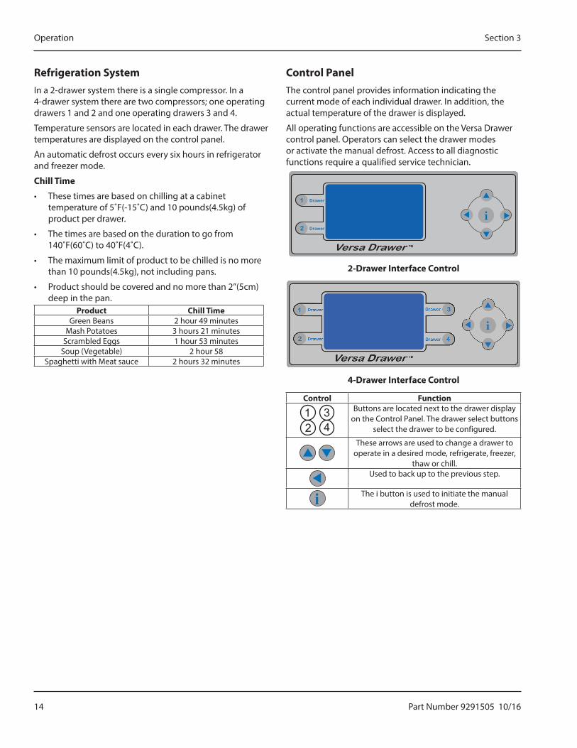
Control PanelThe control panel provides information indicating the current mode of each individual drawer. In addition, the actual temperature of the drawer is displayed.
All operating functions are accessible on the Versa Drawer control panel. Operators can select the drawer modes or activate the manual defrost. Access to all diagnostic functions require a qualified service technician.
2-Drawer Interface Control
4-Drawer Interface Control
Control Function
21
43 Buttons are located next to the drawer display
on the Control Panel. The drawer select buttons select the drawer to be configured.
These arrows are used to change a drawer to operate in a desired mode, refrigerate, freezer,
thaw or chill.Used to back up to the previous step.
The i button is used to initiate the manual defrost mode.
Part Number 9291505 10/16 15
Section 3 Operation
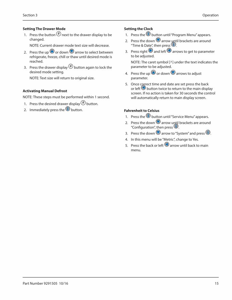
Setting The Drawer Mode
1. Press the button # next to the drawer display to be changed.
NOTE: Current drawer mode text size will decrease.
2. Press the up or down arrow to select between refrigerate, freeze, chill or thaw until desired mode is reached.
3. Press the drawer display # button again to lock the desired mode setting.
NOTE: Text size will return to original size.
Activating Manual Defrost
NOTE: These steps must be performed within 1 second.
1. Press the desired drawer display # button.
2. Immediately press the button.
Setting the Clock
1. Press the button until “Program Menu” appears.
2. Press the down arrow until brackets are around “Time & Date”, then press .
3. Press right and left arrows to get to parameter to be adjusted.
NOTE: The caret symbol [^] under the text indicates the parameter to be adjusted.
4. Press the up or down arrows to adjust parameter.
5. Once correct time and date are set press the back or left button twice to return to the main display screen. If no action is taken for 30 seconds the control will automatically return to main display screen.
Fahrenheit to Celsius
1. Press the button until “Service Menu” appears.
2. Press the down arrow until brackets are around “Configuration”, then press .
3. Press the down arrow to “System” and press .
4. In this menu will be “Metric”, change to Yes.
5. Press the back or left arrow until back to main menu.
16 Part Number 9291505 10/16
Operation Section 3
THIS PAGE INTENTIONALLY LEFT BLANK
Part Number 9291505 10/16 17
DANGERIt is the responsibility of the equipment owner to perform a Personal Protective Equipment Hazard Assessment to ensure adequate protection during maintenance procedures.
DANGERFailure to disconnect the power at the main power supply disconnect could result in serious injury or death. The power switch DOES NOT disconnect all incoming power.
DANGERDisconnect electric power at the main power disconnect for all equipment being serviced. Observe correct polarity of incoming line voltage. Incorrect polarity can lead to erratic operation.
nWarningNever use sharp objects or tools to remove ice or frost. Do not use mechanical devices or other means to accelerate the defrosting process.
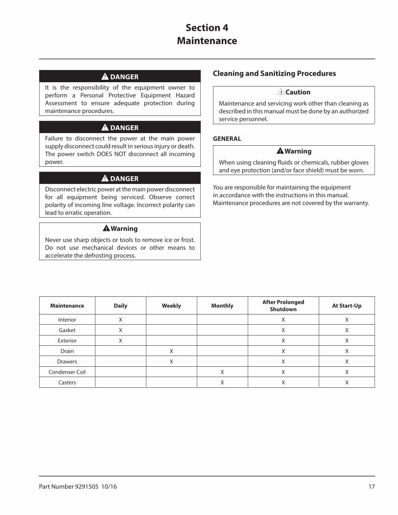
Cleaning and Sanitizing Procedures
,CautionMaintenance and servicing work other than cleaning as described in this manual must be done by an authorized service personnel.
GENERAL
nWarningWhen using cleaning fluids or chemicals, rubber gloves and eye protection (and/or face shield) must be worn.
You are responsible for maintaining the equipment in accordance with the instructions in this manual. Maintenance procedures are not covered by the warranty.
Section 4Maintenance
Maintenance Daily Weekly Monthly After Prolonged Shutdown At Start-Up
Interior X X X
Gasket X X X
Exterior X X X
Drain X X X
Drawers X X X
Condenser Coil X X X
Casters X X X
18 Part Number 9291505 10/16
Maintenance Section 4
INTERIOR CLEANING
nWarningWhen cleaning interior and exterior of unit, care should be taken to avoid the front power switch and the rear power cord. Keep water and/or cleaning solutions away from these parts.
nWarningNever use a high-pressure water jet for cleaning or hose down or flood interior or exterior of units with water. Do not use power cleaning equipment, steel wool, scrapers or wire brushes on stainless steel or painted surfaces.
The interior can be cleaned using soap and warm water. If this isn’t sufficient, try ammonia and water or a nonabrasive liquid cleaner.
Preventing Blower Coil Corrosion
To help prevent corrosion of the blower coil, store all acidic items, such as pickles and tomatoes, in seal-able containers. Immediately wipe up all spills.
EXTERIOR CLEANING
,CautionNever use an acid based cleaning solution on exterior panels! Many food products have an acidic content, which can deteriorate the finish. Be sure to clean the stainless steel surfaces of ALL food products.
Clean the area around the unit as often as necessary to maintain cleanliness and efficient operation.
Wipe exterior surfaces with a damp cloth rinsed in water to remove dust and dirt from the outside of the unit. Always rub with the “grain” of the stainless steel to avoid marring the finish. If a greasy residue persists, use a damp cloth rinsed in a mild dish soap and water solution. Wipe dry with a clean, soft cloth.
Never use steel wool or abrasive pads for cleaning. Never use chlorinated, citrus based or abrasive cleaners.
Stainless steel exterior panels have a clear coating that is stain resistant and easy to clean. Products containing abrasives will damage the coating and scratch the panels. Daily cleaning may be followed by an application of stainless steel cleaner which will eliminate water spotting and fingerprints. Early signs of stainless steel breakdown are small pits and cracks. If this has begun, clean thoroughly and start to apply stainless steel cleaners in attempt to restore the steel.
Gasket Cleaning
Gaskets require daily cleaning to prevent mold and mildew build up and also to keep the elasticity of the gasket. Gasket cleaning can be done with the use of warm soapy water. Avoid full strength cleaning products on gaskets as this can cause them to become brittle and prevent proper seals. Never use sharp tools or knives to scrape or clean the gasket, which could possibly tear the gasket and rip the bellows.
Drawer gaskets are magnetic and mount to the drawer, snapping in place and are removable without tools.
CASTERSWipe casters with a damp cloth monthly to prevent corrosion.
Part Number 9291505 10/16 19
Section 4 Maintenance
DRAWER MAINTENANCEDrawer Assembly Cleaning
The drawer assembly is designed to be cleaned easily. Both drawer and tracks are removable without tools. The drawer tracks are dishwasher safe or can be cleaned in a sink with detergents and a soft bristle brush. Drawers and tracks should be cleaned on a weekly basis.
Remove Drawers
Pull the drawer box out until it stops. Lift up on the drawer front and pull the drawer box completely out. Using a soft bristle brush, clean the track on the bottom of the drawer box. When finished, it should be wiped clean of all food and debris.
Tracks
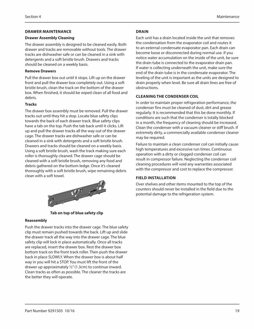
The drawer box assembly must be removed. Pull the drawer tracks out until they hit a stop. Locate blue safety clips towards the back of each drawer track. Blue safety clips have a tab on the top. Push the tab back until it clicks. Lift up and pull the drawer tracks all the way out of the drawer cage. The drawer tracks are dishwasher safe or can be cleaned in a sink with detergents and a soft bristle brush. Drawers and tracks should be cleaned on a weekly basis. Using a soft bristle brush, wash the track making sure each roller is thoroughly cleaned. The drawer cage should be cleaned with a soft bristle brush, removing any food and debris gathered on the bottom ledge. Once it’s cleaned thoroughly with a soft bristle brush, wipe remaining debris clean with a soft towel.
Tab on top of blue safety clip
Reassembly
Push the drawer tracks into the drawer cage. The blue safety clip must remain pushed towards the back. Lift up and slide the drawer track all the way into the drawer cage. The blue safety clip will lock in place automatically. Once all tracks are replaced, insert the drawer box. Rest the drawer box bottom track on the front track roller. Then push the drawer back in place SLOWLY. When the drawer box is about half way in you will hit a STOP. You must lift the front of the drawer up approximately ½” (1.3cm) to continue inward. Clean tracks as often as possible. The cleaner the tracks are the better they will operate.
DRAINEach unit has a drain located inside the unit that removes the condensation from the evaporator coil and routes it to an external condensate evaporator pan. Each drain can become loose or disconnected during normal use. If you notice water accumulation on the inside of the unit, be sure the drain tube is connected to the evaporator drain pan. If water is collecting underneath the unit, make sure the end of the drain tube is in the condensate evaporator. The leveling of the unit is important as the units are designed to drain properly when level. Be sure all drain lines are free of obstructions.
CLEANING THE CONDENSER COILIn order to maintain proper refrigeration performance, the condenser fins must be cleaned of dust, dirt and grease regularly. It is recommended that this be done monthly. If conditions are such that the condenser is totally blocked in a month, the frequency of cleaning should be increased. Clean the condenser with a vacuum cleaner or stiff brush. If extremely dirty, a commercially available condenser cleaner may be required.
Failure to maintain a clean condenser coil can initially cause high temperatures and excessive run times. Continuous operation with a dirty or clogged condenser coil can result in compressor failure. Neglecting the condenser coil cleaning procedures will void any warranties associated with the compressor and cost to replace the compressor.
FIELD INSTALLATIONOver shelves and other items mounted to the top of the counters should never be installed in the field due to the potential damage to the refrigeration system.
20 Part Number 9291505 10/16
Maintenance Section 4
THIS PAGE INTENTIONALLY LEFT BLANK
Part Number 9291505 10/16 21
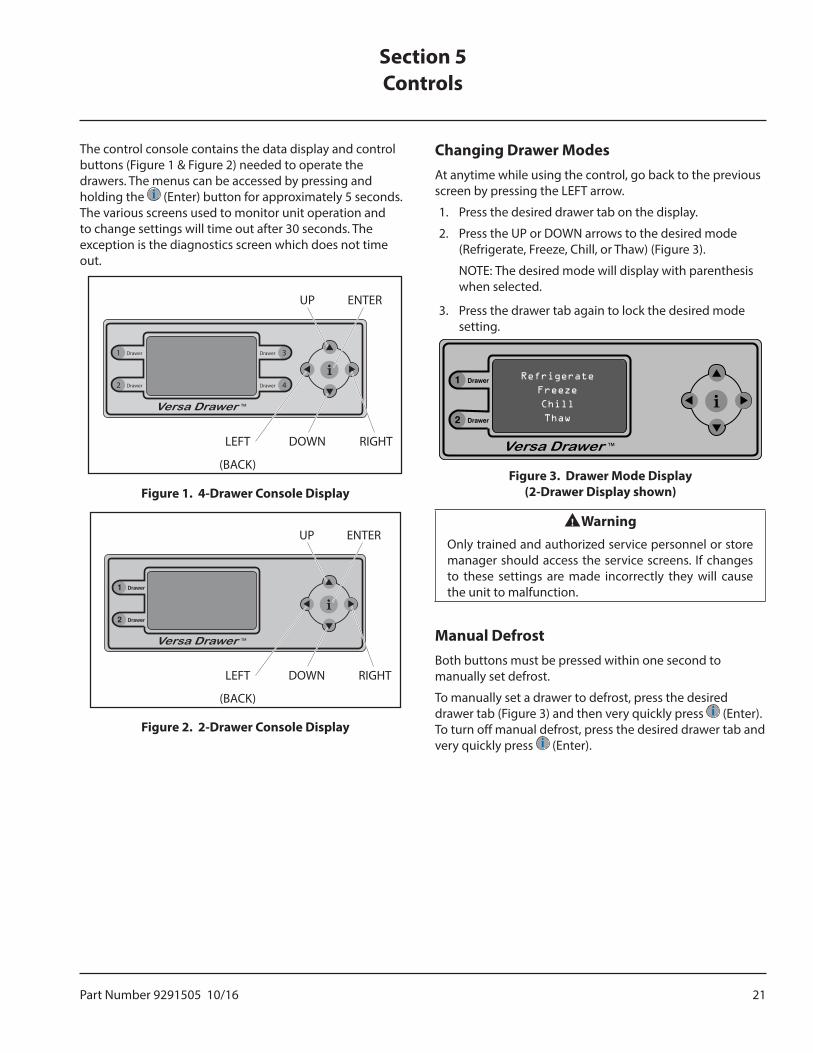
The control console contains the data display and control buttons (Figure 1 & Figure 2) needed to operate the drawers. The menus can be accessed by pressing and holding the (Enter) button for approximately 5 seconds. The various screens used to monitor unit operation and to change settings will time out after 30 seconds. The exception is the diagnostics screen which does not time out.
1 Drawer
2 Drawer
Drawer
Drawer
3
4
LEFT
(BACK)
DOWN
UP ENTER
RIGHT
Figure 1. 4-Drawer Console Display
LEFT
(BACK)
DOWN
UP ENTER
RIGHT
Figure 2. 2-Drawer Console Display
Changing Drawer ModesAt anytime while using the control, go back to the previous screen by pressing the LEFT arrow.
1. Press the desired drawer tab on the display.
2. Press the UP or DOWN arrows to the desired mode (Refrigerate, Freeze, Chill, or Thaw) (Figure 3).
NOTE: The desired mode will display with parenthesis when selected.
3. Press the drawer tab again to lock the desired mode setting.
Figure 3. Drawer Mode Display (2-Drawer Display shown)
nWarningOnly trained and authorized service personnel or store manager should access the service screens. If changes to these settings are made incorrectly they will cause the unit to malfunction.
Manual DefrostBoth buttons must be pressed within one second to manually set defrost.
To manually set a drawer to defrost, press the desired drawer tab (Figure 3) and then very quickly press (Enter). To turn off manual defrost, press the desired drawer tab and very quickly press (Enter).
Section 5Controls
22 Part Number 9291505 10/16
Controls Section 5
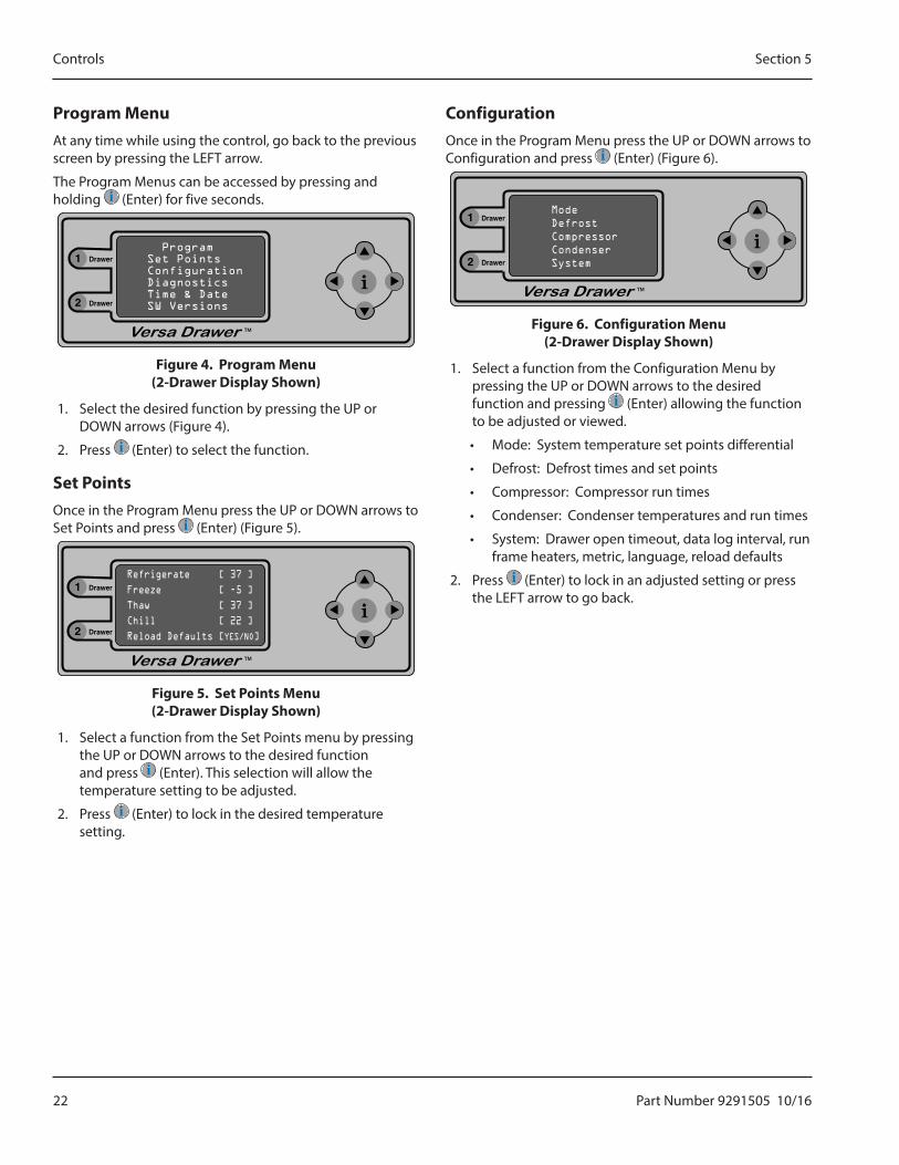
Program MenuAt any time while using the control, go back to the previous screen by pressing the LEFT arrow.
The Program Menus can be accessed by pressing and holding (Enter) for five seconds.
Figure 4. Program Menu (2-Drawer Display Shown)
1. Select the desired function by pressing the UP or DOWN arrows (Figure 4).
2. Press (Enter) to select the function.
Set PointsOnce in the Program Menu press the UP or DOWN arrows to Set Points and press (Enter) (Figure 5).
Figure 5. Set Points Menu (2-Drawer Display Shown)
1. Select a function from the Set Points menu by pressing the UP or DOWN arrows to the desired function and press (Enter). This selection will allow the temperature setting to be adjusted.
2. Press (Enter) to lock in the desired temperature setting.
ConfigurationOnce in the Program Menu press the UP or DOWN arrows to Configuration and press (Enter) (Figure 6).
Figure 6. Configuration Menu (2-Drawer Display Shown)
1. Select a function from the Configuration Menu by pressing the UP or DOWN arrows to the desired function and pressing (Enter) allowing the function to be adjusted or viewed.
• Mode: System temperature set points differential
• Defrost: Defrost times and set points
• Compressor: Compressor run times
• Condenser: Condenser temperatures and run times
• System: Drawer open timeout, data log interval, run frame heaters, metric, language, reload defaults
2. Press (Enter) to lock in an adjusted setting or press the LEFT arrow to go back.

Part Number 9291505 10/16 23
Section 5 Controls
DiagnosticsOnce in the Program Menu press the UP or DOWN arrows to Diagnostics and press (Enter) for diagnostics display (Figure 7).
Drawer
Drawer
3
4
Figure 7. Diagnostics Menu (4-Drawer Display Shown)
Drawer
Drawer
3
4
Drawer
Drawer
3
4
Drawer
Drawer
3
4
Figure 8. Drawer Status
The status of each drawer is detailed in a column below it’s location, #1, #2, #3 or #4.
• Mode, Box Temperature, Evaporator Temperature are listed at the top.
• If the hot gas solenoid is powered there will be a H in the Heat row under the corresponding drawer.
• If the cooling solenoid is powered there will be a C in the Cool row under the corresponding drawer.
• If a fan is powered there will a F in the Fans row under the corresponding drawer.
• If the frame heater is powered there will be a W in the Wire row under the corresponding drawer.
• If the drawer switch is open there will be an O in the Open Drawer row under the corresponding drawer.
Time and DateOnce in the Program Menu press the UP or DOWN arrows to Time & Date and press (Enter) allowing the time and date to display.
1. Adjust the time and date by pressing the RIGHT arrow to the desired digit location and the UP or DOWN arrow to the proper digit.
2. Press (Enter) to lock in the setting.
3. Repeat for each digit location on the screen.
4. When completed press (Enter) then the LEFT arrow to exit the Time and Date screen.
Software VersionsOnce in the Program Menu press the UP or DOWN arrows to SW Versions (Figure 9) and press (Enter) allowing the software versions to display.
Figure 9. Software Versions Display (2-Drawer Display Shown)
NOTE: The software versions in Figure 9 are shown as examples only and are not the actual software versions.
24 Part Number 9291505 10/16
Controls Section 5
THIS PAGE INTENTIONALLY LEFT BLANK
Part Number 9291505 10/16 25
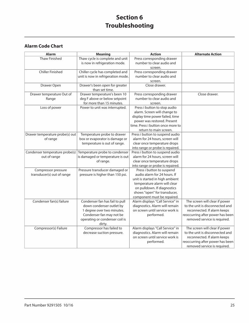
Alarm Code Chart
Alarm Meaning Action Alternate ActionThaw Finished Thaw cycle is complete and unit
is now in refrigeration mode.Press corresponding drawer number to clear audio and
screen.Chiller Finished Chiller cycle has completed and
unit is now in refrigeration mode.Press corresponding drawer number to clear audio and
screen.Drawer Open Drawer's been open for greater
than set time.Close drawer.
Drawer temperature Out of Range
Drawer temperature's been 10 deg F above or below setpoint
for more than 15 minutes.
Press corresponding drawer number to clear audio and
screen.
Close drawer.
Loss of power Power to unit was interrupted. Press i button to stop audio alarm. Screen will change to
display time power failed, time power was restored. Present
time. Press i button once more to return to main screen.
Drawer temperature probe(s) out of range
Temperature probe to drawer box or evaporator is damage or
temperature is out of range.
Press i button to suspend audio alarm for 24 hours, screen will clear once temperature drops
into range or probe is repaired.Condenser temperature probe(s)
out of rangeTemperature probe to condenser is damaged or temperature is out
of range.
Press i button to suspend audio alarm for 24 hours, screen will clear once temperature drops
into range or probe is repaired.Compressor pressure
transducer(s) out of rangePressure transducer damaged or pressure is higher than 150 psi.
Press i button to suspend audio alarm for 24 hours. If
unit is started in high ambient temperature alarm will clear on pulldown. If diagnostics
shows "open" for transducer, component must be repaired.
Condenser fan(s) failure Condenser fan has fail to pull down condenser outlet by 1 degree over two minutes. Condenser fan may not be
operating or condenser coil is dirty.
Alarm displays "Call Service" in diagnostics. Alarm will remain on screen until service work is
performed.
The screen will clear if power to the unit is disconnected and
reconnected. If alarm keeps reoccurring after power has been
removed service is required.
Compressor(s) Failure Compressor has failed to decrease suction pressure.
Alarm displays "Call Service" in diagnostics. Alarm will remain on screen until service work is
performed.
The screen will clear if power to the unit is disconnected and
reconnected. If alarm keeps reoccurring after power has been
removed service is required.
Section 6Troubleshooting
26 Part Number 9291505 10/16
Troubleshooting Section 6
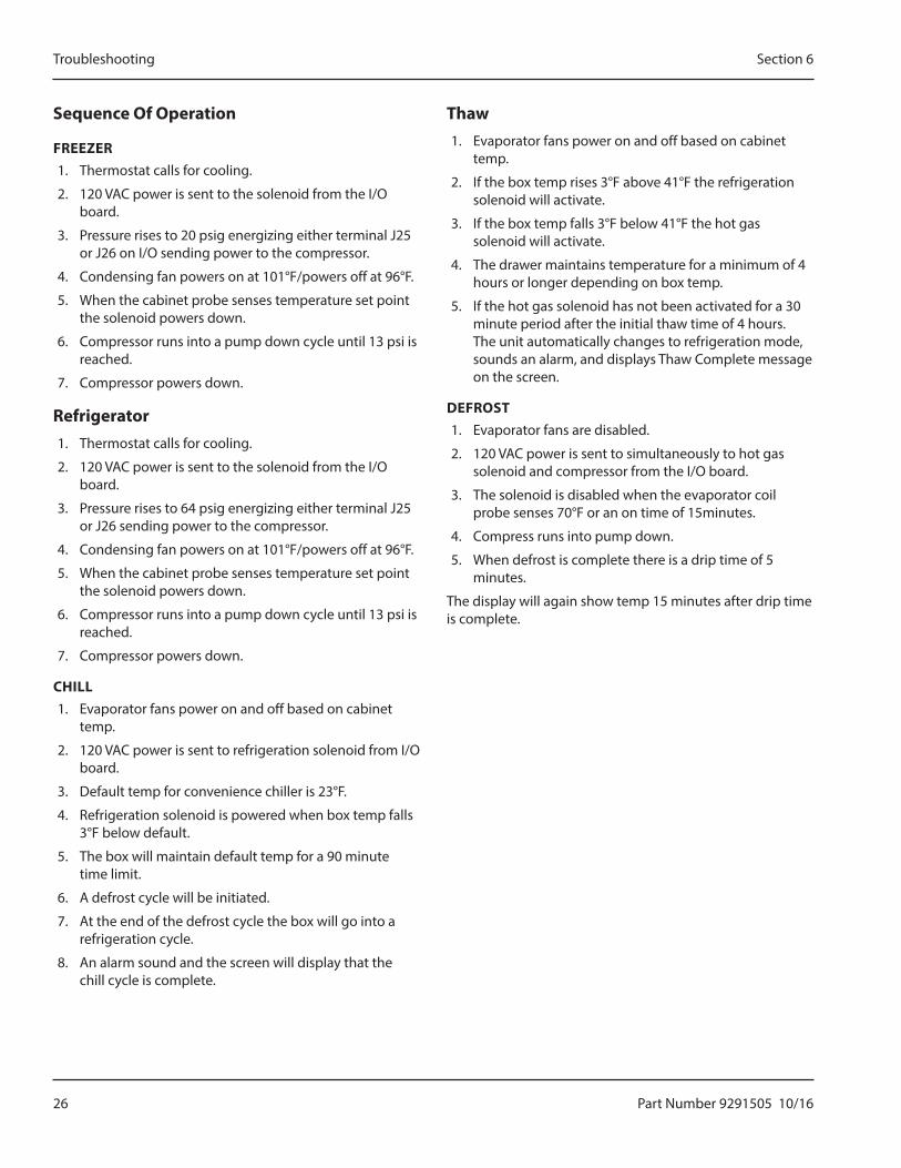
Sequence Of Operation
FREEZER1. Thermostat calls for cooling.
2. 120 VAC power is sent to the solenoid from the I/O board.
3. Pressure rises to 20 psig energizing either terminal J25 or J26 on I/O sending power to the compressor.
4. Condensing fan powers on at 101°F/powers off at 96°F.
5. When the cabinet probe senses temperature set point the solenoid powers down.
6. Compressor runs into a pump down cycle until 13 psi is reached.
7. Compressor powers down.
Refrigerator1. Thermostat calls for cooling.
2. 120 VAC power is sent to the solenoid from the I/O board.
3. Pressure rises to 64 psig energizing either terminal J25 or J26 sending power to the compressor.
4. Condensing fan powers on at 101°F/powers off at 96°F.
5. When the cabinet probe senses temperature set point the solenoid powers down.
6. Compressor runs into a pump down cycle until 13 psi is reached.
7. Compressor powers down.
CHILL1. Evaporator fans power on and off based on cabinet
temp.
2. 120 VAC power is sent to refrigeration solenoid from I/O board.
3. Default temp for convenience chiller is 23°F.
4. Refrigeration solenoid is powered when box temp falls 3°F below default.
5. The box will maintain default temp for a 90 minute time limit.
6. A defrost cycle will be initiated.
7. At the end of the defrost cycle the box will go into a refrigeration cycle.
8. An alarm sound and the screen will display that the chill cycle is complete.
Thaw1. Evaporator fans power on and off based on cabinet
temp.
2. If the box temp rises 3°F above 41°F the refrigeration solenoid will activate.
3. If the box temp falls 3°F below 41°F the hot gas solenoid will activate.
4. The drawer maintains temperature for a minimum of 4 hours or longer depending on box temp.
5. If the hot gas solenoid has not been activated for a 30 minute period after the initial thaw time of 4 hours. The unit automatically changes to refrigeration mode, sounds an alarm, and displays Thaw Complete message on the screen.
DEFROST1. Evaporator fans are disabled.
2. 120 VAC power is sent to simultaneously to hot gas solenoid and compressor from the I/O board.
3. The solenoid is disabled when the evaporator coil probe senses 70°F or an on time of 15minutes.
4. Compress runs into pump down.
5. When defrost is complete there is a drip time of 5 minutes.
The display will again show temp 15 minutes after drip time is complete.
Part Number 9291505 10/16 27
Section 6 Troubleshooting
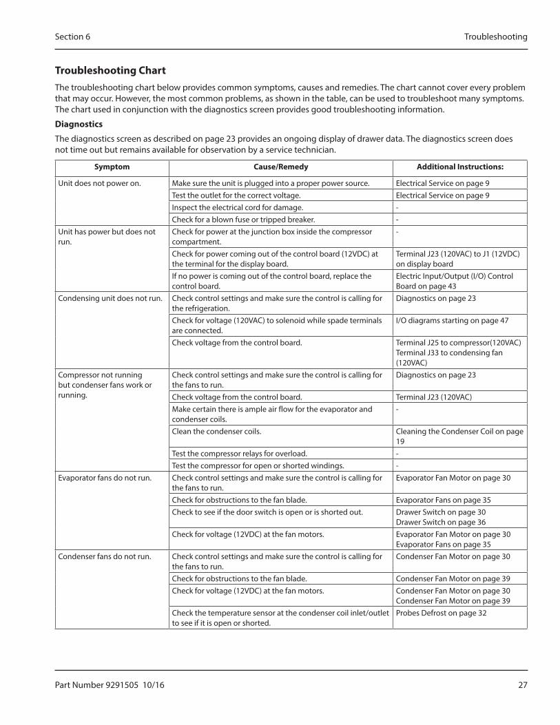
Troubleshooting ChartThe troubleshooting chart below provides common symptoms, causes and remedies. The chart cannot cover every problem that may occur. However, the most common problems, as shown in the table, can be used to troubleshoot many symptoms. The chart used in conjunction with the diagnostics screen provides good troubleshooting information.
Diagnostics
The diagnostics screen as described on page 23 provides an ongoing display of drawer data. The diagnostics screen does not time out but remains available for observation by a service technician.
Symptom Cause/Remedy Additional Instructions:
Unit does not power on. Make sure the unit is plugged into a proper power source. Electrical Service on page 9Test the outlet for the correct voltage. Electrical Service on page 9Inspect the electrical cord for damage. -Check for a blown fuse or tripped breaker. -
Unit has power but does not run.
Check for power at the junction box inside the compressor compartment.
-
Check for power coming out of the control board (12VDC) at the terminal for the display board.
Terminal J23 (120VAC) to J1 (12VDC) on display board
If no power is coming out of the control board, replace the control board.
Electric Input/Output (I/O) Control Board on page 43
Condensing unit does not run. Check control settings and make sure the control is calling for the refrigeration.
Diagnostics on page 23
Check for voltage (120VAC) to solenoid while spade terminals are connected.
I/O diagrams starting on page 47
Check voltage from the control board. Terminal J25 to compressor(120VAC)Terminal J33 to condensing fan (120VAC)
Compressor not running but condenser fans work or running.
Check control settings and make sure the control is calling for the fans to run.
Diagnostics on page 23
Check voltage from the control board. Terminal J23 (120VAC)Make certain there is ample air flow for the evaporator and condenser coils.
-
Clean the condenser coils. Cleaning the Condenser Coil on page 19
Test the compressor relays for overload. -Test the compressor for open or shorted windings. -
Evaporator fans do not run. Check control settings and make sure the control is calling for the fans to run.
Evaporator Fan Motor on page 30
Check for obstructions to the fan blade. Evaporator Fans on page 35Check to see if the door switch is open or is shorted out. Drawer Switch on page 30
Drawer Switch on page 36Check for voltage (12VDC) at the fan motors. Evaporator Fan Motor on page 30
Evaporator Fans on page 35Condenser fans do not run. Check control settings and make sure the control is calling for
the fans to run.Condenser Fan Motor on page 30
Check for obstructions to the fan blade. Condenser Fan Motor on page 39Check for voltage (12VDC) at the fan motors. Condenser Fan Motor on page 30
Condenser Fan Motor on page 39Check the temperature sensor at the condenser coil inlet/outlet to see if it is open or shorted.
Probes Defrost on page 32
28 Part Number 9291505 10/16
Troubleshooting Section 6
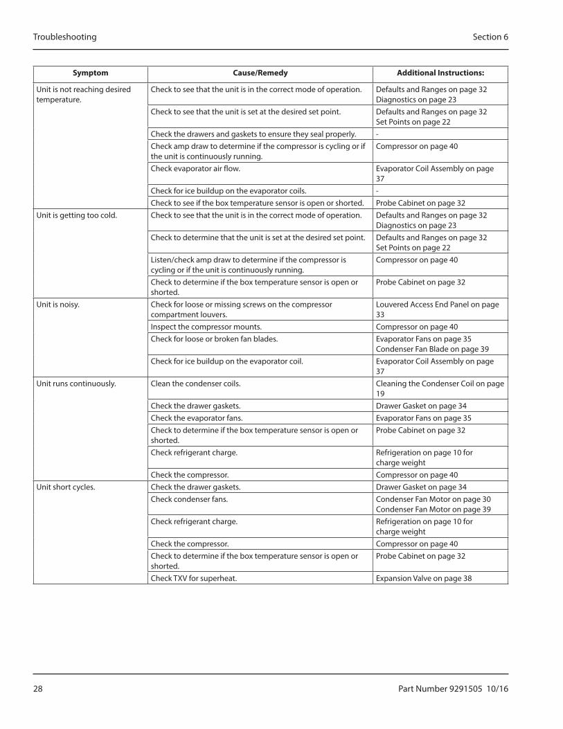
Symptom Cause/Remedy Additional Instructions:
Unit is not reaching desired temperature.
Check to see that the unit is in the correct mode of operation. Defaults and Ranges on page 32Diagnostics on page 23
Check to see that the unit is set at the desired set point. Defaults and Ranges on page 32Set Points on page 22
Check the drawers and gaskets to ensure they seal properly. -Check amp draw to determine if the compressor is cycling or if the unit is continuously running.
Compressor on page 40
Check evaporator air flow. Evaporator Coil Assembly on page 37
Check for ice buildup on the evaporator coils. -Check to see if the box temperature sensor is open or shorted. Probe Cabinet on page 32
Unit is getting too cold. Check to see that the unit is in the correct mode of operation. Defaults and Ranges on page 32Diagnostics on page 23
Check to determine that the unit is set at the desired set point. Defaults and Ranges on page 32Set Points on page 22
Listen/check amp draw to determine if the compressor is cycling or if the unit is continuously running.
Compressor on page 40
Check to determine if the box temperature sensor is open or shorted.
Probe Cabinet on page 32
Unit is noisy. Check for loose or missing screws on the compressor compartment louvers.
Louvered Access End Panel on page 33
Inspect the compressor mounts. Compressor on page 40Check for loose or broken fan blades. Evaporator Fans on page 35
Condenser Fan Blade on page 39Check for ice buildup on the evaporator coil. Evaporator Coil Assembly on page
37Unit runs continuously. Clean the condenser coils. Cleaning the Condenser Coil on page
19Check the drawer gaskets. Drawer Gasket on page 34Check the evaporator fans. Evaporator Fans on page 35Check to determine if the box temperature sensor is open or shorted.
Probe Cabinet on page 32
Check refrigerant charge. Refrigeration on page 10 for charge weight
Check the compressor. Compressor on page 40Unit short cycles. Check the drawer gaskets. Drawer Gasket on page 34
Check condenser fans. Condenser Fan Motor on page 30Condenser Fan Motor on page 39
Check refrigerant charge. Refrigeration on page 10 for charge weight
Check the compressor. Compressor on page 40Check to determine if the box temperature sensor is open or shorted.
Probe Cabinet on page 32
Check TXV for superheat. Expansion Valve on page 38
Part Number 9291505 10/16 29
Section 6 Troubleshooting
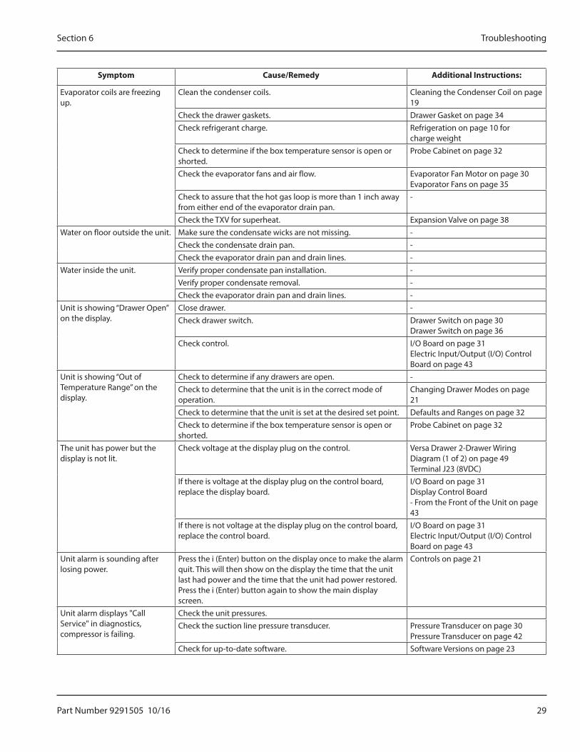
Symptom Cause/Remedy Additional Instructions:
Evaporator coils are freezing up.
Clean the condenser coils. Cleaning the Condenser Coil on page 19
Check the drawer gaskets. Drawer Gasket on page 34Check refrigerant charge. Refrigeration on page 10 for
charge weightCheck to determine if the box temperature sensor is open or shorted.
Probe Cabinet on page 32
Check the evaporator fans and air flow. Evaporator Fan Motor on page 30Evaporator Fans on page 35
Check to assure that the hot gas loop is more than 1 inch away from either end of the evaporator drain pan.
-
Check the TXV for superheat. Expansion Valve on page 38Water on floor outside the unit. Make sure the condensate wicks are not missing. -
Check the condensate drain pan. -Check the evaporator drain pan and drain lines. -
Water inside the unit. Verify proper condensate pan installation. -Verify proper condensate removal. -Check the evaporator drain pan and drain lines. -
Unit is showing “Drawer Open” on the display.
Close drawer. -Check drawer switch. Drawer Switch on page 30
Drawer Switch on page 36Check control. I/O Board on page 31
Electric Input/Output (I/O) Control Board on page 43
Unit is showing “Out of Temperature Range” on the display.
Check to determine if any drawers are open. -Check to determine that the unit is in the correct mode of operation.
Changing Drawer Modes on page 21
Check to determine that the unit is set at the desired set point. Defaults and Ranges on page 32Check to determine if the box temperature sensor is open or shorted.
Probe Cabinet on page 32
The unit has power but the display is not lit.
Check voltage at the display plug on the control. Versa Drawer 2-Drawer Wiring Diagram (1 of 2) on page 49Terminal J23 (8VDC)
If there is voltage at the display plug on the control board, replace the display board.
I/O Board on page 31Display Control Board - From the Front of the Unit on page 43
If there is not voltage at the display plug on the control board, replace the control board.
I/O Board on page 31Electric Input/Output (I/O) Control Board on page 43
Unit alarm is sounding after losing power.
Press the i (Enter) button on the display once to make the alarm quit. This will then show on the display the time that the unit last had power and the time that the unit had power restored. Press the i (Enter) button again to show the main display screen.
Controls on page 21
Unit alarm displays "Call Service" in diagnostics, compressor is failing.
Check the unit pressures.Check the suction line pressure transducer. Pressure Transducer on page 30
Pressure Transducer on page 42Check for up-to-date software. Software Versions on page 23
30 Part Number 9291505 10/16
Troubleshooting Section 6
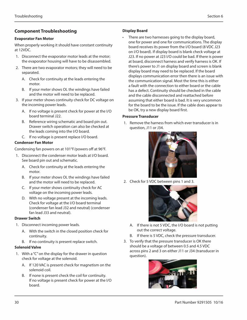
Component TroubleshootingEvaporator Fan Motor
When properly working it should have constant continuity at 12VDC.
1. Disconnect the evaporator motor leads at the motor; the evaporator housing will have to be disassembled.
2. There are two evaporator motors; they will need to be separated.
A. Check for continuity at the leads entering the motor.
B. If your meter shows OL the windings have failed and the motor will need to be replaced.
3. If your meter shows continuity check for DC voltage on the incoming power leads.
A. If no voltage is present check for power at the I/O board terminal J22.
B. Reference wiring schematic and board pin out. Drawer switch operation can also be checked at the leads coming into the I/O board.
C. If no voltage is present replace I/O board.Condenser Fan Motor
Condensing fan powers on at 101°F/powers off at 96°F.
1. Disconnect the condenser motor leads at I/O board. See board pin out and schematic.
A. Check for continuity at the leads entering the motor.
B. If your meter shows OL the windings have failed and the motor will need to be replaced.
C. If your meter shows continuity check for AC voltage on the incoming power leads.
D. With no voltage present at the incoming leads. Check for voltage at the I/O board terminal (condenser fan lead J32 and neutral) (condenser fan lead J33 and neutral).
Drawer Switch
1. Disconnect incoming power leads.
A. With the switch in the closed position check for continuity.
B. If no continuity is present replace switch.Solenoid Valve
1. With a “C” on the display for the drawer in question check for voltage at the solenoid.
A. If 120 VAC is present check for magnetism on the solenoid coil.
B. If none is present check the coil for continuity. If no voltage is present check for power at the I/O board.
Display Board
• There are two harnesses going to the display board, one for power and one for communications. The display board receives its power from the I/O board (8 VDC J23 on I/O board). If display board is blank check voltage at J23. If no power at J23 I/O could be bad. If there is power at board, disconnect harness and verify harness is OK. If there’s power to J1 on display board and screen is blank display board may need to be replaced. If the board displays communication error then there is an issue with the communication signal. Most the time this is either a fault with the connection to either board or the cable has a defect. Continuity should be checked in the cable and the cable disconnected and reattached before assuming that either board is bad. It is very uncommon for the board to be the issue. If the cable does appear to be OK, try a new display board first.
Pressure Transducer
1. Remove the harness from which ever transducer is in question, J11 or J34.
2. Check for 5 VDC between pins 1 and 3.
A. If there is not 5 VDC, the I/O board is not putting out the correct voltage.
B. If there is 5 VDC, check the pressure transducer.3. To verify that the pressure transducer is OK there
should be a voltage of between 0.5 and 4.5 VDC across pins 2 and 3 on either J11 or J34 (transducer in question).
Part Number 9291505 10/16 31
Section 6 Troubleshooting
I/O Board
1. Is the cabinet temperature above the set point for current mode?
• If not, the unit and I/O board are operating normally.
2. If the cabinet temperature is higher than it should be, is it in defrost mode? A H will be on the screen below the corresponding drawer.
• If yes, wait for defrost to complete and enter cooling mode. Return to Step 1.
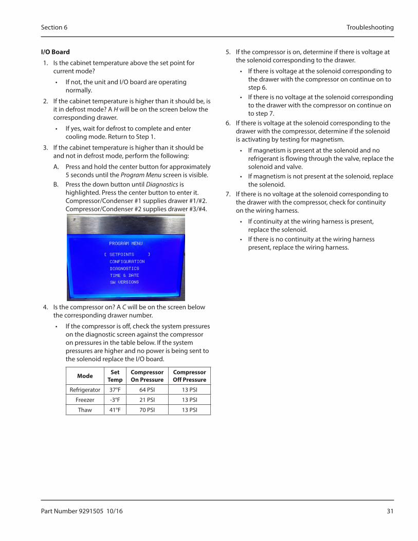
3. If the cabinet temperature is higher than it should be and not in defrost mode, perform the following:
A. Press and hold the center button for approximately 5 seconds until the Program Menu screen is visible.
B. Press the down button until Diagnostics is highlighted. Press the center button to enter it. Compressor/Condenser #1 supplies drawer #1/#2. Compressor/Condenser #2 supplies drawer #3/#4.
4. Is the compressor on? A C will be on the screen below the corresponding drawer number.
• If the compressor is off, check the system pressures on the diagnostic screen against the compressor on pressures in the table below. If the system pressures are higher and no power is being sent to the solenoid replace the I/O board.
Mode Set Temp
Compressor On Pressure
Compressor Off Pressure
Refrigerator 37°F 64 PSI 13 PSI
Freezer -3°F 21 PSI 13 PSI
Thaw 41°F 70 PSI 13 PSI
5. If the compressor is on, determine if there is voltage at the solenoid corresponding to the drawer.
• If there is voltage at the solenoid corresponding to the drawer with the compressor on continue on to step 6.
• If there is no voltage at the solenoid corresponding to the drawer with the compressor on continue on to step 7.
6. If there is voltage at the solenoid corresponding to the drawer with the compressor, determine if the solenoid is activating by testing for magnetism.
• If magnetism is present at the solenoid and no refrigerant is flowing through the valve, replace the solenoid and valve.
• If magnetism is not present at the solenoid, replace the solenoid.
7. If there is no voltage at the solenoid corresponding to the drawer with the compressor, check for continuity on the wiring harness.
• If continuity at the wiring harness is present, replace the solenoid.
• If there is no continuity at the wiring harness present, replace the wiring harness.
32 Part Number 9291505 10/16
Troubleshooting Section 6
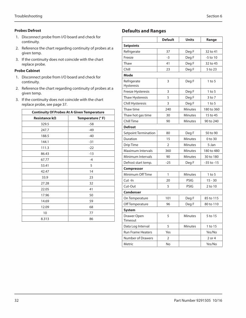
Probes Defrost
1. Disconnect probe from I/O board and check for continuity.
2. Reference the chart regarding continuity of probes at a given temp.
3. If the continuity does not coincide with the chart replace probe.
Probe Cabinet
1. Disconnect probe from I/O board and check for continuity.
2. Reference the chart regarding continuity of probes at a given temp.
3. If the continuity does not coincide with the chart replace probe, see page 37.
Continuity Of Probes At A Given Temperature
Resistance kΩ Temperature (° F)
329.5 -58
247.7 -49
188.5 -40
144.1 -31
111.3 -22
86.43 -13
67.77 -4
53.41 5
42.47 14
33.9 23
27.28 32
22.05 41
17.96 50
14.69 59
12.09 68
10 77
8.313 86
Defaults and Ranges
Default Units Range
Setpoints
Refrigerate 37 Deg F 32 to 41
Freeze -3 Deg F -5 to 10
Thaw 41 Deg F 32 to 45
Chill 23 Deg F 5 to 23
Mode
Refrigerate Hysteresis
3 Deg F 1 to 5
Freeze Hysteresis 3 Deg F 1 to 5
Thaw Hysteresis 5 Deg F 3 to 7
Chill Hysteresis 3 Deg F 1 to 5
Thaw time 240 Minutes 180 to 360
Thaw hot gas time 30 Minutes 15 to 45
Chill Time 90 Minutes 90 to 240
Defrost
Setpoint Termination 80 Deg F 50 to 90
Duration 15 Minutes 0 to 30
Drip Time 2 Minutes 5-Jan
Maximum Intervals 360 Minutes 180 to 480
Minimum Intervals 90 Minutes 30 to 180
Defrost start temp. -25 Deg F -35 to -15
Compressor
Minimum Off Time 1 Minutes 1 to 5
Cut -In 20 PSIG 15 - 30
Cut-Out 5 PSIG 2 to 10
Condenser
On Temperature 101 Deg F 85 to 115
Off Temperature 96 Deg F 80 to 110
System
Drawer Open Timeout
5 Minutes 5 to 15
Data Log Interval 5 Minutes 1 to 15
Run Frame Heaters Yes Yes/No
Number of Drawers 2 2 or 4
Metric No Yes/No
Part Number 9291505 10/16 33
Lo Profile and 2-Drawer refrigeration units use one compressor, one accumulator, one receiver and four solenoids. In addition, one evaporator is used for each drawer along with support components. The 4-Drawer refrigeration unit uses two complete 2-Drawer units. Component removal and replacement is similar for both types.
Perform the following procedures to remove and replace parts. To eliminate mistakes when ordering parts, always provide the following information:
• Model Number
• Serial Number
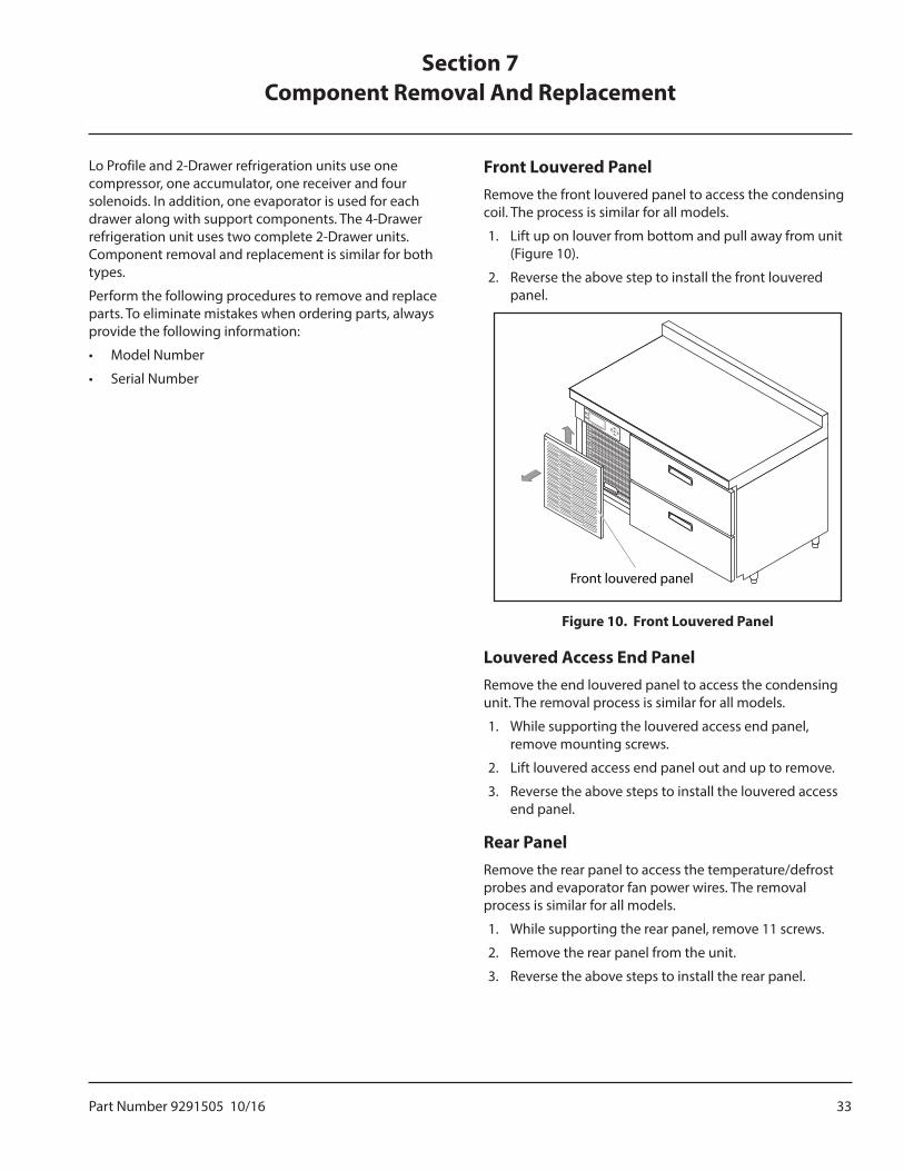
Front Louvered PanelRemove the front louvered panel to access the condensing coil. The process is similar for all models.
1. Lift up on louver from bottom and pull away from unit (Figure 10).
2. Reverse the above step to install the front louvered panel.
Front louvered panel
Figure 10. Front Louvered Panel
Louvered Access End PanelRemove the end louvered panel to access the condensing unit. The removal process is similar for all models.
1. While supporting the louvered access end panel, remove mounting screws.
2. Lift louvered access end panel out and up to remove.
3. Reverse the above steps to install the louvered access end panel.
Rear PanelRemove the rear panel to access the temperature/defrost probes and evaporator fan power wires. The removal process is similar for all models.
1. While supporting the rear panel, remove 11 screws.
2. Remove the rear panel from the unit.
3. Reverse the above steps to install the rear panel.
Section 7Component Removal And Replacement
34 Part Number 9291505 10/16
Component Removal And Replacement Section 7
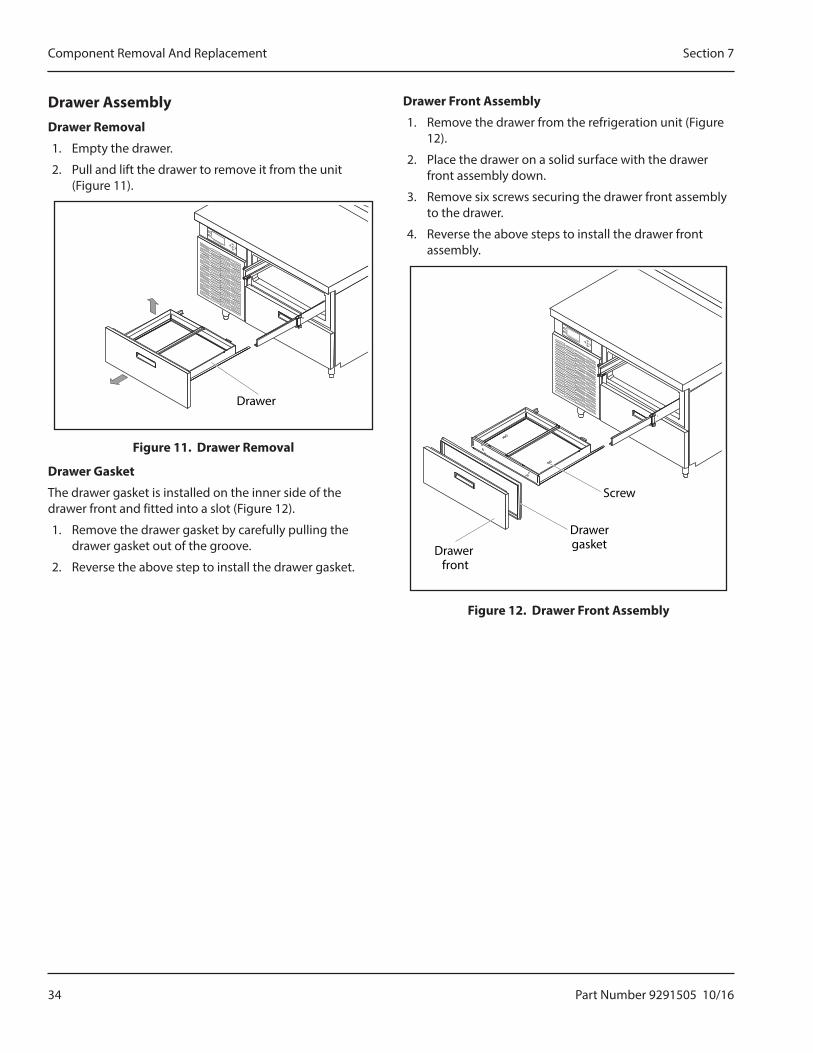
Drawer AssemblyDrawer Removal
1. Empty the drawer.
2. Pull and lift the drawer to remove it from the unit (Figure 11).
Drawer
Figure 11. Drawer Removal
Drawer Gasket
The drawer gasket is installed on the inner side of the drawer front and fitted into a slot (Figure 12).
1. Remove the drawer gasket by carefully pulling the drawer gasket out of the groove.
2. Reverse the above step to install the drawer gasket.
Drawer Front Assembly
1. Remove the drawer from the refrigeration unit (Figure 12).
2. Place the drawer on a solid surface with the drawer front assembly down.
3. Remove six screws securing the drawer front assembly to the drawer.
4. Reverse the above steps to install the drawer front assembly.
Drawerfront
Drawergasket
Screw
Figure 12. Drawer Front Assembly
Part Number 9291505 10/16 35
Section 7 Component Removal And Replacement
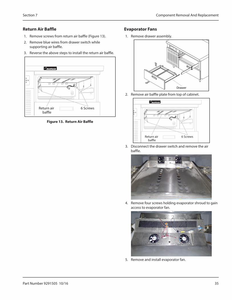
Return Air Baffle1. Remove screws from return air baffle (Figure 13).
2. Remove blue wires from drawer switch while supporting air baffle.
3. Reverse the above steps to install the return air baffle.
Return airbaffle
6 Screws
Figure 13. Return Air Baffle
Evaporator Fans 1. Remove drawer assembly.
Drawer
2. Remove air baffle plate from top of cabinet.
Return airbaffle
6 Screws
3. Disconnect the drawer switch and remove the air baffle.
4. Remove four screws holding evaporator shroud to gain access to evaporator fan.
5. Remove and install evaporator fan.

36 Part Number 9291505 10/16
Component Removal And Replacement Section 7
Drawer Switch1. Remove drawer assembly.
Drawer
2. Lower air baffle.
Return airbaffle
6 Screws
3. Disconnect leads from drawer switch.
4. Press tabs on each side of drawer switch and push through the baffle.
Evaporator Coil Assembly CoverEvaporator coil assembly cover removal is similar for all models.
1. The evaporator coil assembly cover is mounted behind the drawer (Figure 14).
2. Reach inside the box and remove four screws from the front of the evaporator coil assembly cover.
Evaporator coil assembly cover
Evaporator coil assembly
Figure 14. Evaporator Coil Assembly Cover
3. Tag and disconnect the fan electrical connectors.
4. Remove the evaporator coil assembly cover from the box.
5. Reverse the above steps to install the evaporator coil assembly cover.
Part Number 9291505 10/16 37
Section 7 Component Removal And Replacement
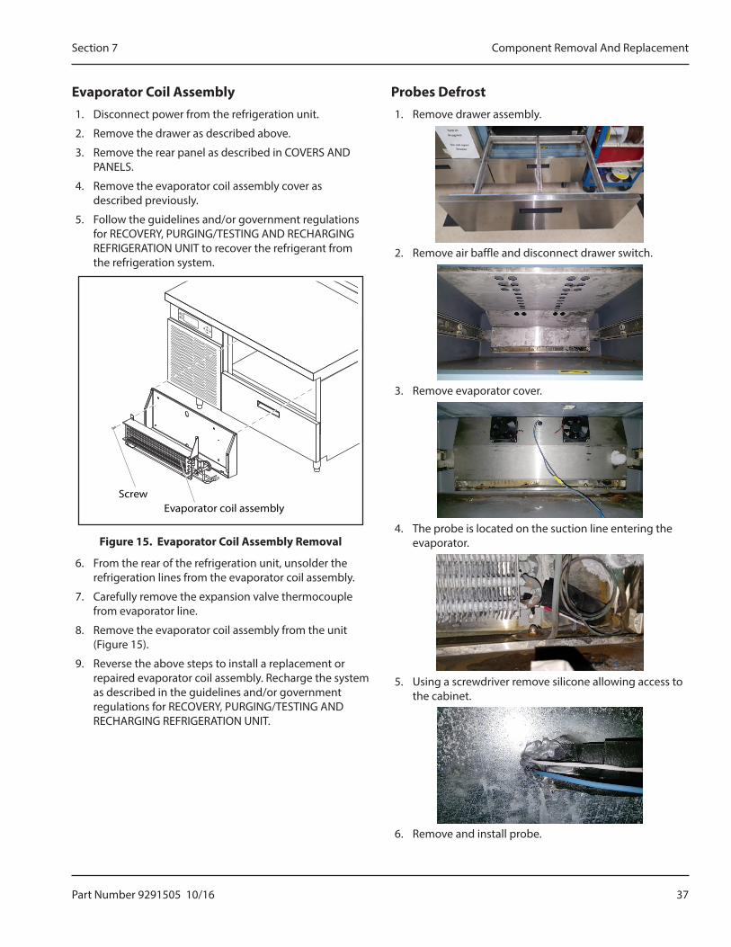
Evaporator Coil Assembly1. Disconnect power from the refrigeration unit.
2. Remove the drawer as described above.
3. Remove the rear panel as described in COVERS AND PANELS.
4. Remove the evaporator coil assembly cover as described previously.
5. Follow the guidelines and/or government regulations for RECOVERY, PURGING/TESTING AND RECHARGING REFRIGERATION UNIT to recover the refrigerant from the refrigeration system.
ScrewEvaporator coil assembly
Figure 15. Evaporator Coil Assembly Removal
6. From the rear of the refrigeration unit, unsolder the refrigeration lines from the evaporator coil assembly.
7. Carefully remove the expansion valve thermocouple from evaporator line.
8. Remove the evaporator coil assembly from the unit (Figure 15).
9. Reverse the above steps to install a replacement or repaired evaporator coil assembly. Recharge the system as described in the guidelines and/or government regulations for RECOVERY, PURGING/TESTING AND RECHARGING REFRIGERATION UNIT.
Probes Defrost1. Remove drawer assembly.
2. Remove air baffle and disconnect drawer switch.
3. Remove evaporator cover.
4. The probe is located on the suction line entering the evaporator.
5. Using a screwdriver remove silicone allowing access to the cabinet.
6. Remove and install probe.
38 Part Number 9291505 10/16
Component Removal And Replacement Section 7
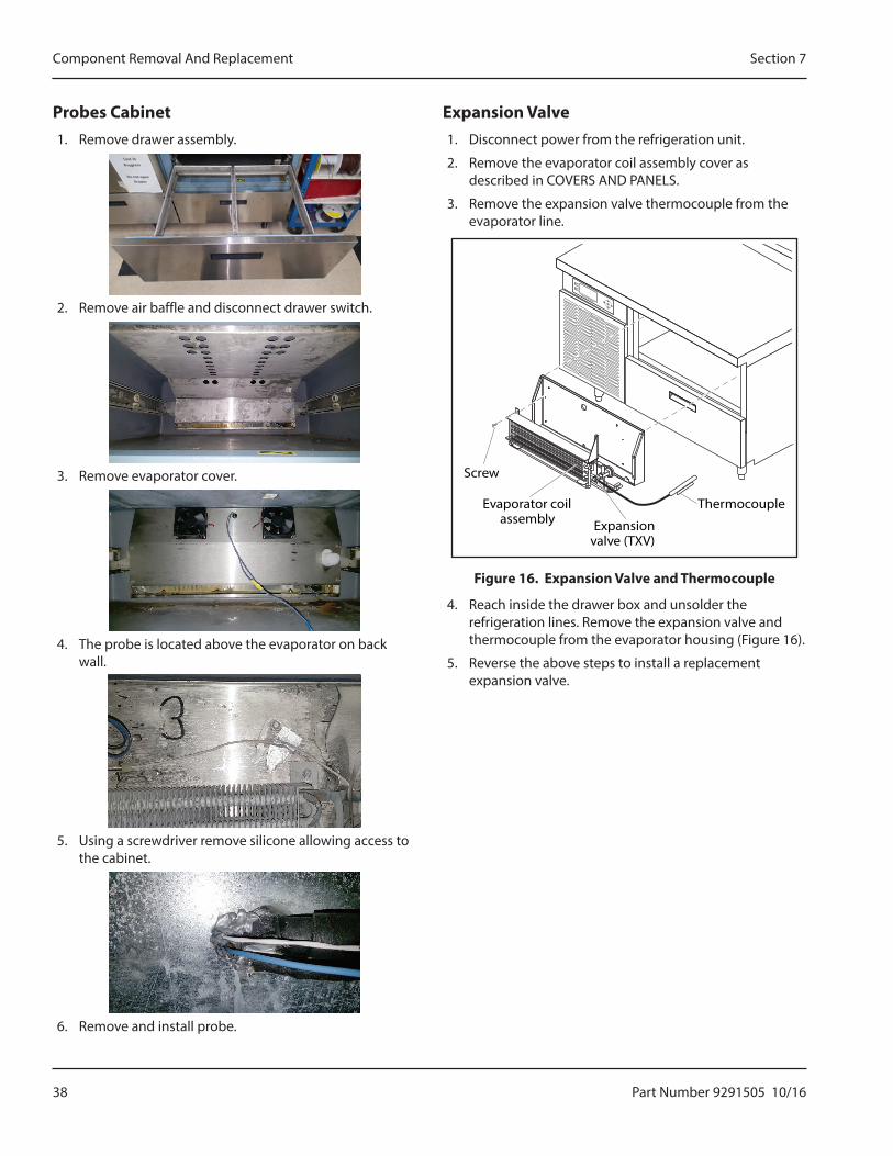
Probes Cabinet1. Remove drawer assembly.
2. Remove air baffle and disconnect drawer switch.
3. Remove evaporator cover.
4. The probe is located above the evaporator on back wall.
5. Using a screwdriver remove silicone allowing access to the cabinet.
6. Remove and install probe.
Expansion Valve1. Disconnect power from the refrigeration unit.
2. Remove the evaporator coil assembly cover as described in COVERS AND PANELS.
3. Remove the expansion valve thermocouple from the evaporator line.
Screw
Evaporator coilassembly Expansion
valve (TXV)
Thermocouple
Figure 16. Expansion Valve and Thermocouple
4. Reach inside the drawer box and unsolder the refrigeration lines. Remove the expansion valve and thermocouple from the evaporator housing (Figure 16).
5. Reverse the above steps to install a replacement expansion valve.
Part Number 9291505 10/16 39
Section 7 Component Removal And Replacement
Condenser Fan Blade1. Disconnect power from the refrigeration unit.
2. Remove the louvered access end panel as described in COVERS AND PANELS.
Condenserfan blade
Nut
Figure 17. Condenser Fan Blade
3. While holding the condenser fan blade (Figure 17), remove the lock nut from the center of the condenser fan blade.
4. Reverse the above steps to install the condenser fan blade.
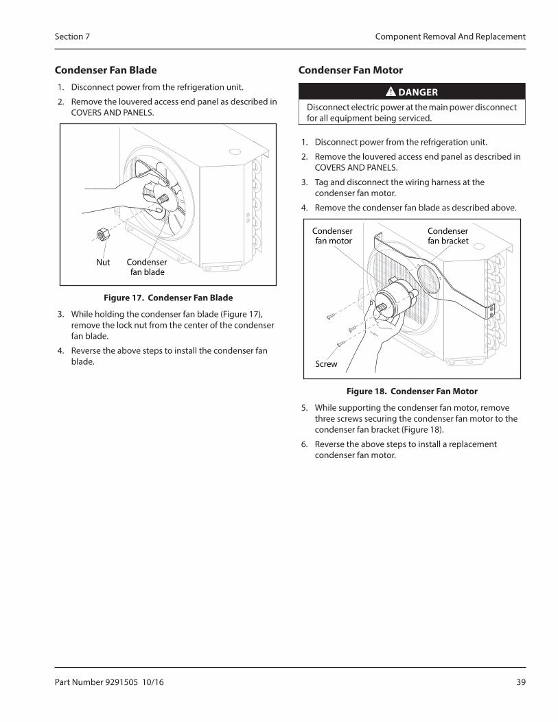
Condenser Fan Motor
DANGERDisconnect electric power at the main power disconnect for all equipment being serviced.
1. Disconnect power from the refrigeration unit.
2. Remove the louvered access end panel as described in COVERS AND PANELS.
3. Tag and disconnect the wiring harness at the condenser fan motor.
4. Remove the condenser fan blade as described above.
Condenserfan bracket
Condenserfan motor
Screw
Figure 18. Condenser Fan Motor
5. While supporting the condenser fan motor, remove three screws securing the condenser fan motor to the condenser fan bracket (Figure 18).
6. Reverse the above steps to install a replacement condenser fan motor.
40 Part Number 9291505 10/16
Component Removal And Replacement Section 7
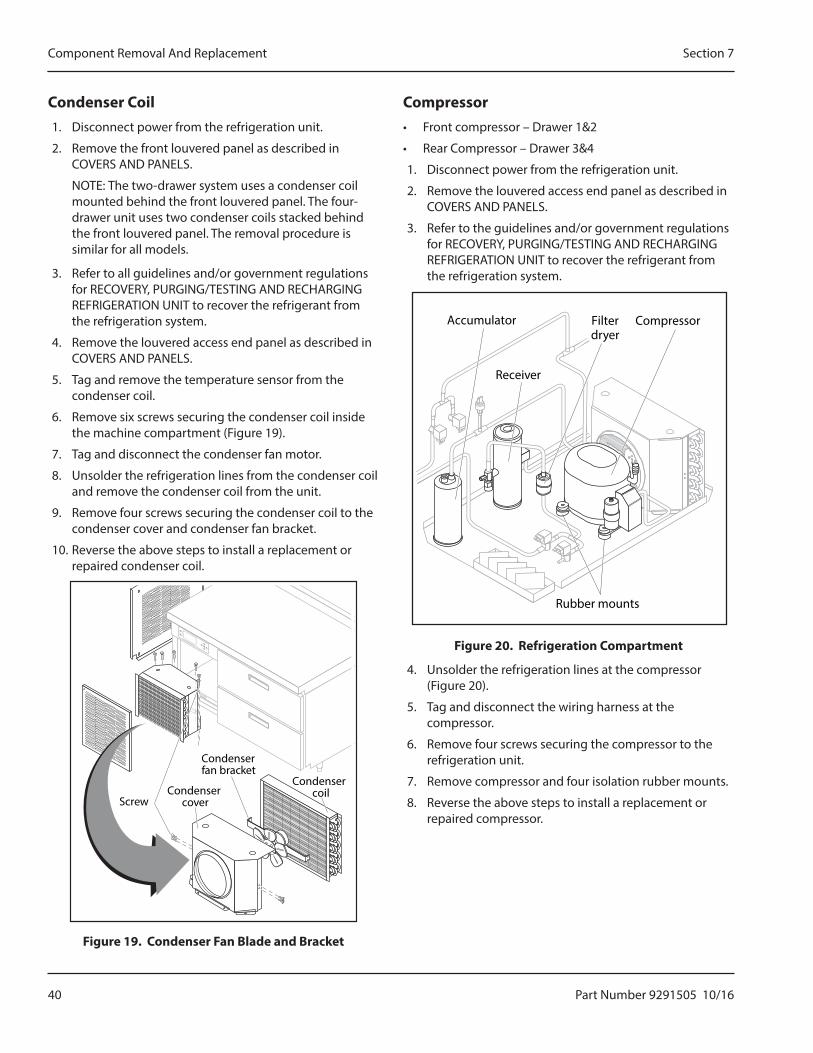
Condenser Coil1. Disconnect power from the refrigeration unit.
2. Remove the front louvered panel as described in COVERS AND PANELS.
NOTE: The two-drawer system uses a condenser coil mounted behind the front louvered panel. The four-drawer unit uses two condenser coils stacked behind the front louvered panel. The removal procedure is similar for all models.
3. Refer to all guidelines and/or government regulations for RECOVERY, PURGING/TESTING AND RECHARGING REFRIGERATION UNIT to recover the refrigerant from the refrigeration system.
4. Remove the louvered access end panel as described in COVERS AND PANELS.
5. Tag and remove the temperature sensor from the condenser coil.
6. Remove six screws securing the condenser coil inside the machine compartment (Figure 19).
7. Tag and disconnect the condenser fan motor.
8. Unsolder the refrigeration lines from the condenser coil and remove the condenser coil from the unit.
9. Remove four screws securing the condenser coil to the condenser cover and condenser fan bracket.
10. Reverse the above steps to install a replacement or repaired condenser coil.
Screw
Condensercoil
Condenserfan bracket
Condensercover
Figure 19. Condenser Fan Blade and Bracket
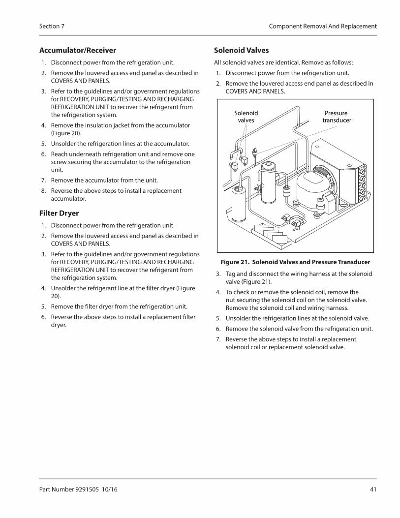
Compressor• Front compressor – Drawer 1&2
• Rear Compressor – Drawer 3&4
1. Disconnect power from the refrigeration unit.
2. Remove the louvered access end panel as described in COVERS AND PANELS.
3. Refer to the guidelines and/or government regulations for RECOVERY, PURGING/TESTING AND RECHARGING REFRIGERATION UNIT to recover the refrigerant from the refrigeration system.
Filterdryer
Accumulator Compressor
Rubber mounts
Receiver
Figure 20. Refrigeration Compartment
4. Unsolder the refrigeration lines at the compressor (Figure 20).
5. Tag and disconnect the wiring harness at the compressor.
6. Remove four screws securing the compressor to the refrigeration unit.
7. Remove compressor and four isolation rubber mounts.
8. Reverse the above steps to install a replacement or repaired compressor.
Part Number 9291505 10/16 41
Section 7 Component Removal And Replacement
Accumulator/Receiver1. Disconnect power from the refrigeration unit.
2. Remove the louvered access end panel as described in COVERS AND PANELS.
3. Refer to the guidelines and/or government regulations for RECOVERY, PURGING/TESTING AND RECHARGING REFRIGERATION UNIT to recover the refrigerant from the refrigeration system.
4. Remove the insulation jacket from the accumulator (Figure 20).
5. Unsolder the refrigeration lines at the accumulator.
6. Reach underneath refrigeration unit and remove one screw securing the accumulator to the refrigeration unit.
7. Remove the accumulator from the unit.
8. Reverse the above steps to install a replacement accumulator.
Filter Dryer1. Disconnect power from the refrigeration unit.
2. Remove the louvered access end panel as described in COVERS AND PANELS.
3. Refer to the guidelines and/or government regulations for RECOVERY, PURGING/TESTING AND RECHARGING REFRIGERATION UNIT to recover the refrigerant from the refrigeration system.
4. Unsolder the refrigerant line at the filter dryer (Figure 20).
5. Remove the filter dryer from the refrigeration unit.
6. Reverse the above steps to install a replacement filter dryer.
Solenoid ValvesAll solenoid valves are identical. Remove as follows:
1. Disconnect power from the refrigeration unit.
2. Remove the louvered access end panel as described in COVERS AND PANELS.
Solenoidvalves
Pressuretransducer
Figure 21. Solenoid Valves and Pressure Transducer
3. Tag and disconnect the wiring harness at the solenoid valve (Figure 21).
4. To check or remove the solenoid coil, remove the nut securing the solenoid coil on the solenoid valve. Remove the solenoid coil and wiring harness.
5. Unsolder the refrigeration lines at the solenoid valve.
6. Remove the solenoid valve from the refrigeration unit.
7. Reverse the above steps to install a replacement solenoid coil or replacement solenoid valve.
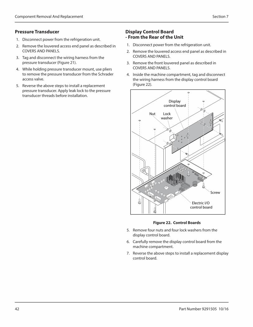
42 Part Number 9291505 10/16
Component Removal And Replacement Section 7
Pressure Transducer1. Disconnect power from the refrigeration unit.
2. Remove the louvered access end panel as described in COVERS AND PANELS.
3. Tag and disconnect the wiring harness from the pressure transducer (Figure 21).
4. While holding pressure transducer mount, use pliers to remove the pressure transducer from the Schrader access valve.
5. Reverse the above steps to install a replacement pressure transducer. Apply leak lock to the pressure transducer threads before installation.
Display Control Board - From the Rear of the Unit1. Disconnect power from the refrigeration unit.
2. Remove the louvered access end panel as described in COVERS AND PANELS.
3. Remove the front louvered panel as described in COVERS AND PANELS.
4. Inside the machine compartment, tag and disconnect the wiring harness from the display control board (Figure 22).
Displaycontrol board
Nut Lockwasher
Electric I/Ocontrol board
Screw
Figure 22. Control Boards
5. Remove four nuts and four lock washers from the display control board.
6. Carefully remove the display control board from the machine compartment.
7. Reverse the above steps to install a replacement display control board.
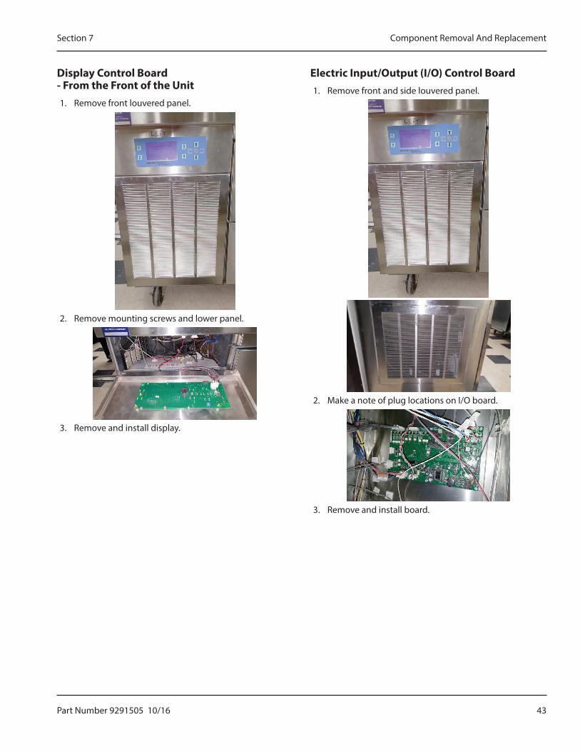
Part Number 9291505 10/16 43
Section 7 Component Removal And Replacement
Display Control Board - From the Front of the Unit1. Remove front louvered panel.
2. Remove mounting screws and lower panel.
3. Remove and install display.
Electric Input/Output (I/O) Control Board1. Remove front and side louvered panel.
2. Make a note of plug locations on I/O board.
3. Remove and install board.
44 Part Number 9291505 10/16
Component Removal And Replacement Section 7
THIS PAGE INTENTIONALLY LEFT BLANK
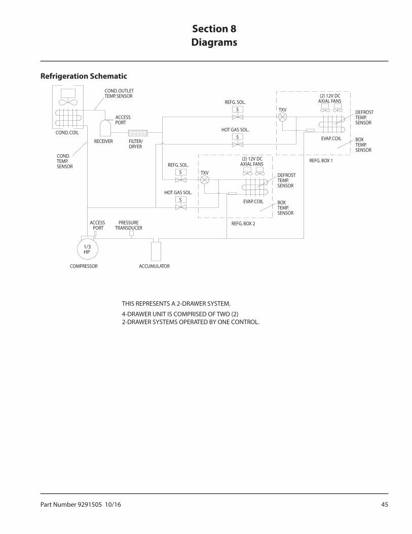
Part Number 9291505 10/16 45
Refrigeration Schematic
THIS REPRESENTS A 2-DRAWER SYSTEM.
4-DRAWER UNIT IS COMPRISED OF TWO (2)2-DRAWER SYSTEMS OPERATED BY ONE CONTROL.
COND.TEMP.SENSOR
COND. COIL
COND. OUTLETTEMP. SENSOR
ACCESSPORT
FILTER/DRYER
RECEIVER
REFG. SOL.S
HOT GAS SOL.S
REFG. SOL.S
HOT GAS SOL.S
TXV
(2) 12V DCAXIAL FANS
EVAP. COIL
REFG. BOX 2
BOXTEMP.SENSOR
DEFROSTTEMP.SENSOR
TXV
(2) 12V DCAXIAL FANS
EVAP. COIL
REFG. BOX 1
BOXTEMP.SENSOR
DEFROSTTEMP.SENSOR
ACCESSPORT
PRESSURETRANSDUCER
ACCUMULATORCOMPRESSOR
1/3HP
Section 8Diagrams
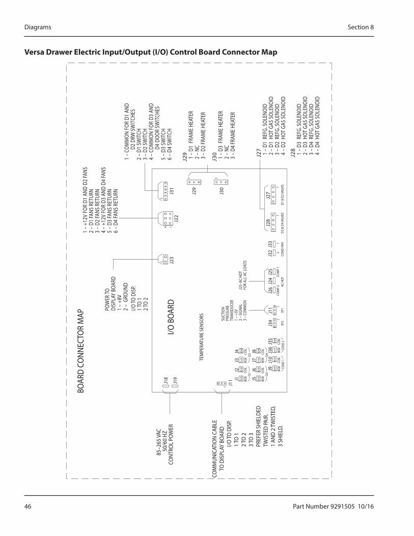
46 Part Number 9291505 10/16
Diagrams Section 8
Versa Drawer Electric Input/Output (I/O) Control Board Connector Map
I/O B
OAR
D
BOAR
D CO
NNEC
TOR
MAP
C
OM
MUN
ICAT
ION
CABL
E
TO
DIS
PLAY
BO
ARD
I/O TO
DIS
P. 1
TO 1
2 TO
23
TO 3
PREF
ER S
HIEL
DED
TWIS
TED
PAIR
.1
AND
2 TW
ISTE
D,3
SHIE
LD.
POW
ER TO
DISP
LAY
BOAR
D1
– +8
V2
– G
ROUN
DI/O
TO D
ISP.
1 TO
12 T
O 2
TEM
PERA
TURE
SEN
SORS SU
CTIO
NPR
ESSU
RETR
ANSD
UCER
1 –
+5V
2 –
SIGN
AL3
– CO
MM
ON
85–2
65 VA
C50
/60
HZCO
NTRO
L PO
WER
J25–
AC H
OTFO
R AL
L AC
LOAD
S
J28
1 –
D3
REF
G. S
OLEN
OID
2 –
D3
HOT
GAS
SOL
ENOI
D 3
– D
4 R
EFG.
SOL
ENOI
D 4
– D
4 H
OT G
AS S
OLEN
OID
J27
1 –
D1
REF
G. S
OLEN
OID
2 –
D1
HOT
GAS
SOL
ENOI
D 3
– D
2 R
EFG.
SOL
ENOI
D 4
– D
2 H
OT G
AS S
OLEN
OID
J29
1 –
D1
FRAM
E HE
ATER
2 –
NC
3 –
D2
FRAM
E HE
ATER
1 –
COM
MON
FOR
D1 A
ND
D2
DRW
SW
ITCH
ES2
– D1
SW
ITCH
3 –
D2 S
WIT
CH4
– CO
MM
ON FO
R D3
AND
D
4 DO
OR S
WIT
CHES
5 –
D3 S
WIT
CH6
– D4
SW
ITCH
1 –
+12V
FOR
D1 A
ND D
2 FA
NS2
– D1
FANS
RET
URN
3 –
D2 FA
NS R
ETUR
N4
– +1
2V FO
R D3
AND
D4
FANS
5 –
D3 FA
NS R
ETUR
N6
– D4
FANS
RET
URN
J30
1 –
D3
FRAM
E HE
ATER
2 –
NC
3 –
D4
FRAM
E HE
ATER
J18
J19
J11
1
J1
D1D2
BOX
J2 COIL
J3 BOX
J4 COIL
J34
SP2
1
J11
SP1
1
J26 AC
HOT
COM
P 2
J25
J24 CO
MP
1CO
ND FA
ND3
& D
4 VA
LVES
J32 2
J33 1
J28
J27
1D1
& D
2 VA
LVES1
J29
J31
J23
J22
1
11
14
J30
1
J9 COND
1CO
ND 2
BOX
J10
COIL
J36
BOX
J35
COIL
J5
D3D4
BOX
J6 COIL
J7 BOX
J8 COIL
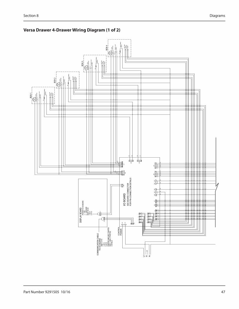
Part Number 9291505 10/16 47
Section 8 Diagrams
Versa Drawer 4-Drawer Wiring Diagram (1 of 2)
GL1
DISP
LAY
BOAR
DPO
WER
TO I/
O BO
ARD
1–
+8V
2–
GROU
NDDI
SP.T
O I/O
1TO
12T
O 2
I/O B
OAR
DSE
E BO
ARD
CONN
ECTO
RFO
R PI
N CO
NNEC
TIO
N DE
TAIL
S
CO
MM
UNIC
ATIO
N CA
BLE
TO I/
O B
OAR
DDI
SP.T
O I/O
1TO
12T
O 2
3TO
3PR
EFER
SHI
ELDE
D TW
ISTE
DPA
IR. 1
AND
2 T
WIS
TED,
3 SH
IELD
.
CONT
ROL
POW
ER
N
J11
1
J2
J18
J19 BO
X
1
J11 J1
J3 BOX
COIL
J2
D1
COIL
J4
D2
36
1 J23
1
4
52 4
1
J22
CON
D 2
BOX
J5J7 BO
X
J6
D3
COIL
J8
D4
COIL
J10
CON
D 1
J9 OU
T
J36
OU
TIN
COM
P 1
J11
SP
1
J35 IN
J34
1S
P2
J26
COM
P 2
1
J24
AC H
OT 2426
J33
J25
J32
12 CO
ND
FAN
J28
D3
& D
4VAL
VE
S
1
3325
3214
1718
13
12V
DC
MTR
35
HEA
TER
SW
ITCH
12V
DC
DRA
WE
R L
IMIT
EVAP
.FA
NS
7
1 2
MTR
MTR
8
34D
RAW
ER
FRA
ME
PR
OB
E
PR
OB
E
EVAP
.TE
MP.
BOX
TEMP
.
1 3
MTR
DRA
WE
R L
IMIT
DRA
WE
R FR
AM
E
EVAP
.TE
MP.
EVAP
.FA
NS
12V
DC
SW
ITCH
7MTR
9
HEA
TER
PR
OB
E
PR
OB
EBO
XTE
MP.
4M
TR
109
1
87
1112
J31
134
J29
1
J30
3635 37
D1
& D
2VAL
VE
S
J27
1
1116
1215
DRA
WE
R L
IMIT
DRA
WE
R FR
AM
E
EVAP
.TE
MP.
12
EVAP
.FA
NS
SW
ITCH
DRA
WE
R L
IMIT
5
10 11
36
HEA
TER
DRA
WE
R FR
AM
E
EVAP
.TE
MP.
10
PR
OB
E
PR
OB
EBO
XTE
MP.
64
EVAP
.FA
NS
12V
DC
MTR
MTR
SW
ITCH
37
HEA
TER
BOX
TEMP
.P
RO
BE
PR
OB
E
BOX
3
BOX
4
BOX
2
BOX
1
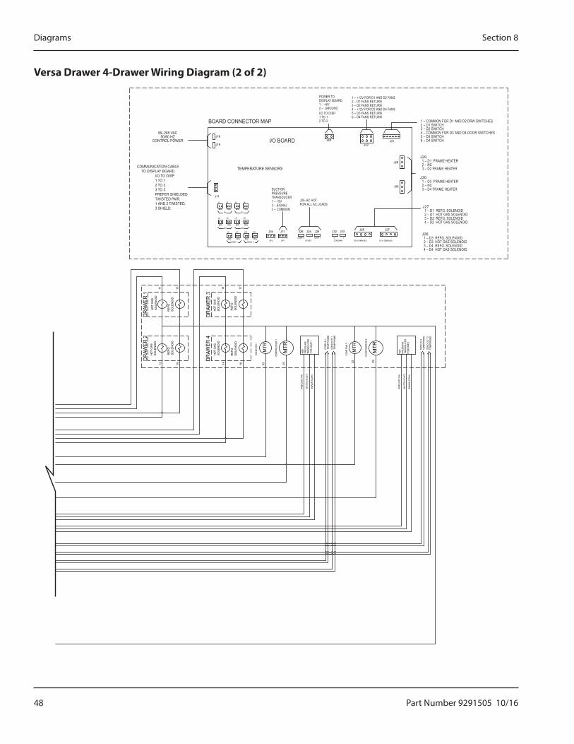
48 Part Number 9291505 10/16
Diagrams Section 8
Versa Drawer 4-Drawer Wiring Diagram (2 of 2)
SP2
J34
SO
LEN
OID
SO
LEN
OID
HOT
GA
S
SO
LEN
OID
SO
LEN
OID
HOT
GA
S
12 16
HOT
GA
SS
OLE
NO
ID
SO
LEN
OID
RE
FG.
RE
FG.
14 18 33
HOT
GA
SS
OLE
NO
ID
SO
LEN
OID
RE
FG.
CO
ND.
FAN
1
MTR
RE
FG.
11 15
BOX
13 17COND 2
COIL
COND 1
BOX COIL
J9
COIL
COIL
D3
BOX
J5
D1
J6
BOX
1
J1
J11
J2
BOX
J10
D4
J36
COIL
BOX
J7
D2
J8
COIL
J35
J3 J4
32M
TR
25
FOR
CO
MP
1
COM
PR
ES
SO
R 1
MTR
TRA
NS
DU
CE
RP
RE
SS
UR
EN
SK CO
ND.
OU
T 1
TEM
P. P
RO
BE
CO
ND. I
N 1
CO
ND.F
AN
2
TEM
P. P
RO
BE
26
WH
ITE
(VO
UT)
BLA
CK
(CO
M)
RE
D(V
DC
IN)
WH
ITE
(VO
UT)
BLA
CK
(CO
M)
RE
D(V
DC
IN)
MTR
CO
MP
RE
SS
OR
2
FORC
OM
P. 2
PR
ES
SU
RE
TRA
NS
DU
CE
R
NS
K TEMP
. PR
OB
E
TEMP
. PR
OB
E
CON
D. O
UT
2
CON
D. IN
2
D3 & D4VALVESAC HOT1
SP11 COMP 2 COMP 1
CONDFAN12
J24J11 J26 J32J25 J33
D1 & D2VALVES
1 1
J30
J28 J27
1
J19
J181
J23
J29
J22
4
1
1
J31
1
DRAW
ER 2
DRAW
ER 1
DRAW
ER 4
DRAW
ER 3
I/O BOARD
BOARD CONNECTOR MAP
COMMUNICATION CABLETO DISPLAY BOARD
I/O TO DISP.1 TO 12 TO 23 TO 3PREFER SHIELDEDTWISTED PAIR.1 AND 2 TWISTED,3 SHIELD.
POWER TODISPLAY BOARD1 – +8V2 – GROUNDI/O TO DISP.1 TO 12 TO 2
TEMPERATURE SENSORS
SUCTIONPRESSURETRANSDUCER1 – +5V2 – SIGNAL3 – COMMON
85–265 VAC50/60 HZ
CONTROL POWER
J25–AC HOTFOR ALL AC LOADS
J28 1 – D3 REFG. SOLENOID 2 – D3 HOT GAS SOLENOID 3 – D4 REFG. SOLENOID 4 – D4 HOT GAS SOLENOID
J27 1 – D1 REFG. SOLENOID 2 – D1 HOT GAS SOLENOID 3 – D2 REFG. SOLENOID 4 – D2 HOT GAS SOLENOID
J29 1 – D1 FRAME HEATER 2 – NC 3 – D2 FRAME HEATER
1 – COMMON FOR D1 AND D2 DRW SWITCHES2 – D1 SWITCH3 – D2 SWITCH4 – COMMON FOR D3 AND D4 DOOR SWITCHES5 – D3 SWITCH6 – D4 SWITCH
1 – +12V FOR D1 AND D2 FANS2 – D1 FANS RETURN3 – D2 FANS RETURN4 – +12V FOR D3 AND D4 FANS5 – D3 FANS RETURN6 – D4 FANS RETURN
J30 1 – D3 FRAME HEATER 2 – NC 3 – D4 FRAME HEATER
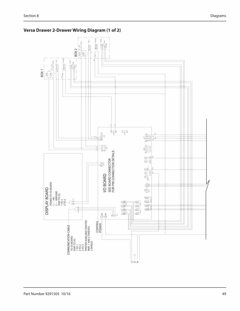
Part Number 9291505 10/16 49
Section 8 Diagrams
Versa Drawer 2-Drawer Wiring Diagram (1 of 2)
DISP
LAY
BOAR
DPO
WER
TO I/
O B
OAR
D1
– +
8V2
– G
ROUN
DDI
SP.T
O I/
O1
TO 1
2TO
2
I/O B
OAR
DSE
E BO
ARD
CONN
ECTO
RFO
R PI
N CO
NNEC
TIO
N DE
TAIL
S
COM
MUN
ICAT
ION
CABL
ETO
I/O
BO
ARD
DISP
.TO
I/O
1TO
12
TO 2
3TO
3PR
EFER
SHI
ELDE
D TW
ISTE
DPA
IR. 1
AND
2 T
WIS
TED,
3 SH
IELD
.
CONT
ROL
POW
ER
L1 G N
BOX
2
BOX
1
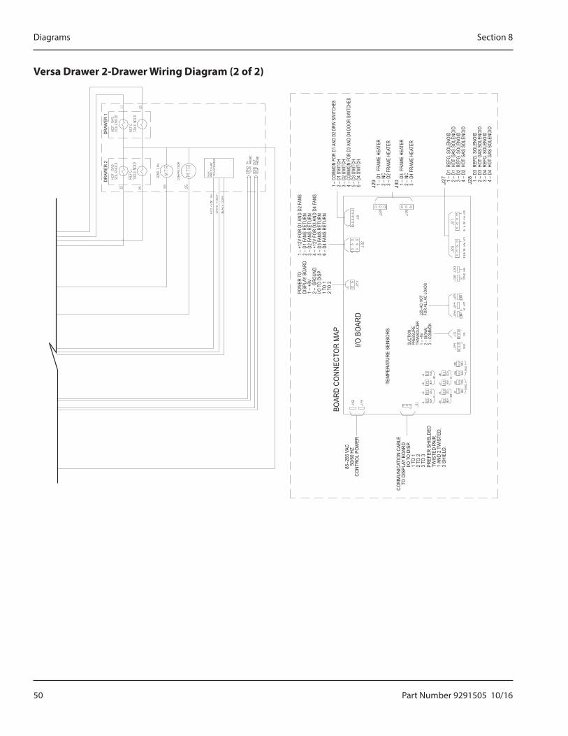
50 Part Number 9291505 10/16
Diagrams Section 8
Versa Drawer 2-Drawer Wiring Diagram (2 of 2)
DRAW
ER 2
DRAW
ER 1
I/O B
OAR
D
BOAR
D CO
NNEC
TOR
MAP
COM
MUN
ICAT
ION
CABL
ETO
DIS
PLAY
BO
ARD
I/OTO
DIS
P.1
TO 1
2TO
23
TO 3
PREF
ER S
HIEL
DED
TWIS
TED
PAIR
.1
AND
2 TW
ISTE
D,3
SHIE
LD.
POW
ER T
ODI
SPLA
Y BO
ARD
1 –
+8V
2 –
GRO
UND
I/O T
O DI
SP.
1 TO
12
TO 2
TEM
PERA
TURE
SEN
SORS
SUCT
ION
PRES
SURE
TRAN
SDUC
ER1
– +5
V2
– SI
GNAL
3 –
COM
MON
85–2
65VA
C50
/60
HZCO
NTRO
L PO
WER
J25–
AC H
OTFO
R AL
L AC
LOA
DS
J28
1 –
D3
REF
G. S
OLEN
OID
2 –
D3
HOT
GAS
SOL
ENOI
D 3
– D
4 R
EFG.
SOL
ENOI
D 4
– D
4 H
OT G
AS S
OLEN
OID
J27
1 –
D1
REF
G. S
OLEN
OID
2 –
D1
HOT
GAS
SOL
ENOI
D 3
– D
2 R
EFG.
SOL
ENOI
D 4
– D
2 H
OT G
AS S
OLEN
OID
J29
1 –
D1
FRA
ME
HEAT
ER 2
– N
C 3
– D
2 FR
AME
HEAT
ER
1 – C
OMMO
N FO
R D1
AND
D2 D
RW S
WIT
CHES
2 – D
1 SW
ITCH
3 – D
2 SW
ITCH
4 – C
OMMO
N FO
R D3
AND
D4 D
OOR
SWIT
CHES
5 – D
3 SW
ITCH
6 – D
4 SW
ITCH
1 –
+12V
FOR
D1
AND
D2 F
ANS
2 –
D1 F
ANS
RETU
RN3
– D2
FAN
S RE
TURN
4 –
+12V
FOR
D3
AND
D4 F
ANS
5 –
D3 F
ANS
RETU
RN6
– D4
FAN
S RE
TURN
J30
1 –
D3
FRA
ME
HEAT
ER 2
– N
C 3
– D
4 FR
AME
HEAT
ER

DELFIELD 980 SOUTH ISABELLA ROAD, MOUNT PLEASANT, MI 48858
800-733-8821 WWW.DELFIELD.COM
To learn how Manitowoc Foodservice and its leading brands can equip you, visit our global web site at www.manitowocfoodservice.com, then discover the regional or local resources available to you.
©2014 Manitowoc Foodservice except where explicitly stated otherwise. All rights reserved. Continuing product improvement may necessitate change of specifications without notice.
Part Number 9291505 10/16
Every new piece of Manitowoc Foodservice equipment comes with KitchenCare™ and you choose the level of service that meets your operational needs from one restaurant to multiple locations.
StarCare – Warranty & lifetime service, certified OEM parts, global parts inventory, performance auditedExtraCare — CareCode, 24/7 Support, online/mobile product informationLifeCare – Install & equipment orientation, planned maintenance, KitchenConnect™, MenuConnectTalk with KitchenCare™ • 1-844-724-CARE • www.mtwkitchencare.com