Embed Size (px)
Citation preview
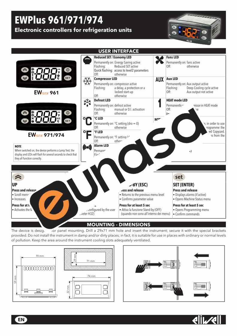
Reduced SET / Economy LEDPermanently on: Energy Saving activeFlashing: Reduced SET activeQuick flashing: access to level2 parametersOff: otherwise
Fans LEDPermanently on: fans activeOff: otherwise
Compressor LEDPermanently on: compressor activeFlashing: a delay, a protection or a locked start-upOff: otherwise
Aux LEDPermanently on: Aux output activeFlashing: Deep Cooling cycle activeOff: Aux output not active
Defrost LEDPermanently on: defrost activeFlashing: manual or D.I. activationOff: otherwise
HEAT mode LEDPermanently on: compressor in HEAT modeOff: otherwise(only EWPlus 961)
°C LEDPermanently on: °C setting (dro = 0)Off: otherwise
NOTE:If the instrument is set in the COOL mode, in order to use it in the HEAT mode it is necessary to reprogramme the instrument by using the properly programmed Copycard. The same procedure should be followed to pass from the HEAT mode to the COOL mode.
°F LEDPermanently on: °F setting (dro = 1)Off: otherwiseAlarm LEDPermanently on: alarm activeFlashing: alarm acknowledgedOff: otherwise
NOT USED(only EWPlus 961)
EWPlus 961/971/974Electronic controllers for refrigeration units
NOTE:When switched on, the device performs a Lamp Test; thedisplay and LEDs will flash for several seconds to check thatthey all function correctly.
USER INTERFACE
UPPress and release• Scroll menu items• Increases values
Press for at least 5 sec• Activates the Manual Defrost function
DOWNPress and release• Scroll menu items• Decrease values
Press for at least 5 sec• Function can be configured by the user ((see parameter H32)
STAND-BY (ESC)Press and release• Returns to the previous menu level• Confirms parameter value
Press for at least 5 sec• Attiva la funzione Stand-by (OFF) (quando non sono all’interno dei menu)
SET (ENTER)Press and release• Displays alarms (if active)• Opens Machine Status menu
Press for at least 5 sec• Opens Programming menu• Confirm commands
KEYs
EN
MOUNTING - DIMENSIONSThe device is designed for panel mounting. Drill a 29x71 mm hole and insert the instrument; secure it with the special brackets provided. Do not install the instrument in damp and/or dirty places; in fact, it is suitable for use in places with ordinary or normal levels of pollution. Keep the area around the instrument cooling slots adequately ventilated.
74 mm
32 m
m
29 m
m
71 mm
70 mm
59 m
m
EWPlus + ECPlus 2/8
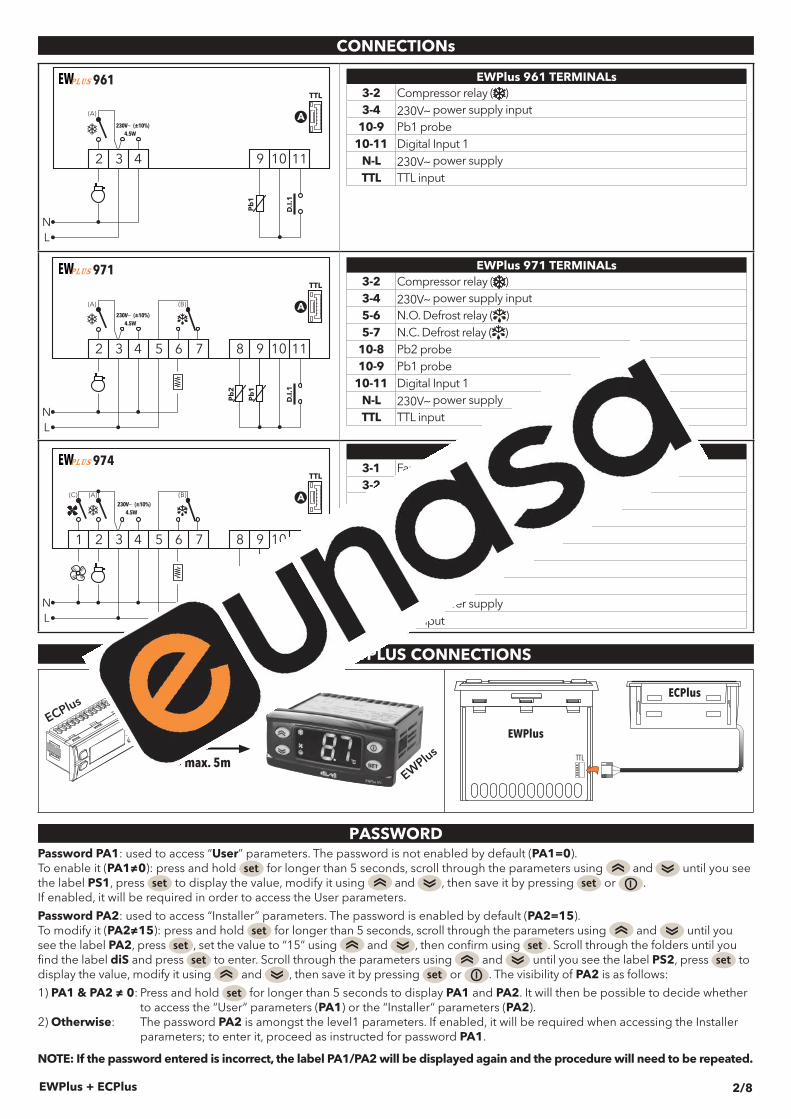
EWPlus 961 TERMINALs3-2 Compressor relay ( )3-4 230Va power supply input
10-9 Pb1 probe10-11 Digital Input 1
N-L 230Va power supply TTL TTL input
NL
2 3 6 7 8 9 10
D.I.1
Pb1
4 5 11
Pb2
(A) (B)
EWPLUS 971
A
TTL
230Va (±10%) 4.5W
EWPlus 971 TERMINALs3-2 Compressor relay ( )3-4 230Va power supply input5-6 N.O. Defrost relay ( )5-7 N.C. Defrost relay ( )
10-8 Pb2 probe10-9 Pb1 probe
10-11 Digital Input 1N-L 230Va power supply TTL TTL input
1
NL
2 3 6 7 8 9 10
(C)
D.I.1
Pb1
4 5 11
Pb2
(A) (B) A
TTL
EWPLUS 974
230Va (±10%) 4.5W
EWPlus 974 TERMINALs3-1 Fans relay ( )3-2 Compressor relay ( )3-4 230Va power supply input5-6 N.O. Defrost relay ( )5-7 N.C. Defrost relay ( )10-8 Pb2 probe10-9 Pb1 probe
10-11 Digital Input 1N-L 230Va power supply TTL TTL input
CONNECTIONs
NL
2 3 9 10
D.I.1
Pb1
4 11
(A) A
TTL
EWPLUS 961
230Va (±10%) 4.5W
PASSWORDPassword PA1: used to access “User” parameters. The password is not enabled by default (PA1=0).To enable it (PA1≠0): press and hold for longer than 5 seconds, scroll through the parameters using and until you seethe label PS1, press to display the value, modify it using and , then save it by pressing or .If enabled, it will be required in order to access the User parameters.
Password PA2: used to access “Installer” parameters. The password is enabled by default (PA2=15).To modify it (PA2≠15): press and hold for longer than 5 seconds, scroll through the parameters using and until yousee the label PA2, press , set the value to “15” using and , then confirm using . Scroll through the folders until youfind the label diS and press to enter. Scroll through the parameters using and until you see the label PS2, press todisplay the value, modify it using and , then save it by pressing or . The visibility of PA2 is as follows:
1) PA1 & PA2 ≠ 0: Press and hold for longer than 5 seconds to display PA1 and PA2. It will then be possible to decide whether to access the “User“ parameters (PA1) or the “Installer“ parameters (PA2).2) Otherwise: The password PA2 is amongst the level1 parameters. If enabled, it will be required when accessing the Installer parameters; to enter it, proceed as instructed for password PA1.
NOTE: If the password entered is incorrect, the label PA1/PA2 will be displayed again and the procedure will need to be repeated.
ECPLUS + EWPLUS CONNECTIONS
ECPlu
s
EWPlu
s TTL
ECPlus
EWPlus
L = max. 5m
EWPlus + ECPlus 3/8
SET POINT EDIT LOCKIt is possible to disable the keypad on this device. The keypad can be locked by programming the ‘LOC’ parameter. With the keypad locked you can still access the ‘Machine Status’ menu by pressing to display the Set point, but you cannot edit them.To disable the keypad lock, repeat the locking procedure.
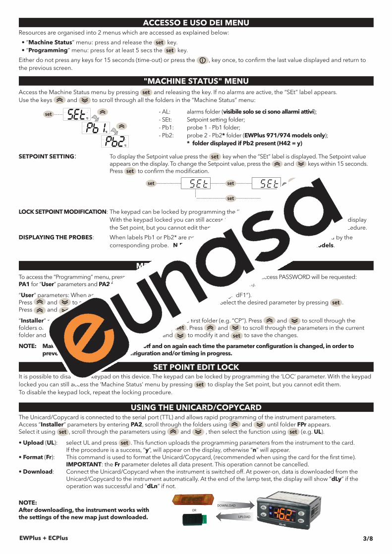
USING THE UNICARD/COPYCARDThe Unicard/Copycard is connected to the serial port (TTL) and allows rapid programming of the instrument parameters.Access “Installer” parameters by entering PA2, scroll through the folders using and until folder FPr appears.Select it using , scroll through the parameters using and , then select the function using (e.g. UL).
• Upload (UL): select UL and press . This function uploads the programming parameters from the instrument to the card. If the procedure is a success, “y”, will appear on the display, otherwise “n” will appear.• Format (Fr): This command is used to format the Unicard/Copycard, (recommended when using the card for the first time). IMPORTANT: the Fr parameter deletes all data present. This operation cannot be cancelled.• Download: Connect the Unicard/Copycard when the instrument is switched off. At power-on, data is downloaded from the Unicard/Copycard to the instrument automatically. At the end of the lamp test, the display will show “dLy” if the operation was successful and “dLn” if not.
NOTE:After downloading, the instrument works withthe settings of the new map just downloaded. UPLOAD
DOWNLOADOR
MENU' DI PROGRAMMAZIONETo access the “Programming” menu, press the key for more than 5 seconds. If specified, an access PASSWORD will be requested:PA1 for “User” parameters and PA2 for “Installer” parameters (see “PASSWORD” paragraph).
“User” parameters: When accessed, the display will show the first parameter (e.g. “dF1”). Press and to scroll through all the parameters on the current level. Select the desired parameter by pressing .Press and to modify it and to save the changes.
“Installer” parameters: When accessed, the display will show the first folder (e.g. “CP”). Press and to scroll through the folders on the current level. Select the desired folder using . Press and to scroll through the parameters in the current folder and select the parameter using . Press and to modify it and to save the changes.
NOTE: Make sure you switch the instrument off and on again each time the parameter configuration is changed, in order to prevent malfunctioning in the configuration and/or timing in progress.
"MACHINE STATUS" MENUAccess the Machine Status menu by pressing and releasing the key. If no alarms are active, the “SEt” label appears.Use the keys and to scroll through all the folders in the “Machine Status” menu:
- AL: alarms folder (visibile solo se ci sono allarmi attivi); - SEt: Setpoint setting folder; - Pb1: probe 1 - Pb1 folder; - Pb2: probe 2 - Pb2* folder (EWPlus 971/974 models only); * folder displayed if Pb2 present (H42 = y)
SETPOINT SETTING: To display the Setpoint value press the key when the “SEt” label is displayed. The Setpoint value appears on the display. To change the Setpoint value, press the and keys within 15 seconds. Press to confirm the modification.
LOCK SETPOINT MODIFICATION: The keypad can be locked by programming the ‘LOC’ parameter. With the keypad locked you can still access the ‘Machine Status’ menu by pressing to display the Set point, but you cannot edit them. To disable the keypad lock, repeat the locking procedure.
DISPLAYING THE PROBES: When labels Pb1 or Pb2* are present, press the key to view the value measured by the corresponding probe. N.B.: 1) Pb2 is only present on EWPlus 971/974 models. 2) the value cannot be modified.
ACCESSO E USO DEI MENUResources are organised into 2 menus which are accessed as explained below:
• “Machine Status” menu: press and release the key. • “Programming” menu: press for at least 5 secs the key.
Either do not press any keys for 15 seconds (time-out) or press the , key once, to confirm the last value displayed and return tothe previous screen.
EWPlus + ECPlus 4/8
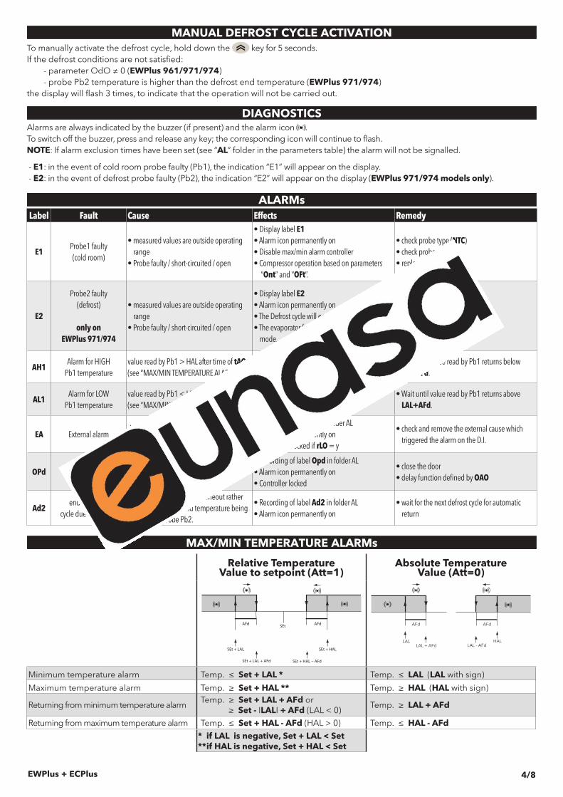
ALARMsLabel Fault Cause Effects Remedy
E1Probe1 faulty(cold room)
• measured values are outside operating range• Probe faulty / short-circuited / open
• Display label E1• Alarm icon permanently on• Disable max/min alarm controller• Compressor operation based on parameters “Ont” and “OFt”.
• check probe type (NTC)• check probe wiring• replace probe
E2
Probe2 faulty(defrost)
only onEWPlus 971/974
• measured values are outside operating range• Probe faulty / short-circuited / open
• Display label E2• Alarm icon permanently on• The Defrost cycle will end due to Timeout (dEt)• The evaporator fans will work in Duty Cycle mode.
• check probe type (NTC)• check probe wiring• replace probe
AH1Alarm for HIGH
Pb1 temperaturevalue read by Pb1 > HAL after time of tAO.(see “MAX/MIN TEMPERATURE ALARMs")
• Recording of label AH1 in folder AL• No effect on regulation
• Wait until value read by Pb1 returns below HAL-AFd.
AL1Alarm for LOW
Pb1 temperaturevalue read by Pb1 < LAL after time of tAO.(see “MAX/MIN TEMPERATURE ALARMs")
• Recording of label AL1 in folder AL• No effect on regulation
• Wait until value read by Pb1 returns above LAL+AFd.
EA External alarmdigital input activation(H11 = ±5)
• Recording of label EA in folder AL• Alarm icon permanently on• Regulation locked if rLO = y
• check and remove the external cause which triggered the alarm on the D.I.
OPd Door open alarmdigital input activation (H11 = ±4)(for longer than tdO)
• Recording of label Opd in folder AL• Alarm icon permanently on• Controller locked
• close the door• delay function defined by OAO
Ad2end of defrost
cycle due to timeout
end of defrost cycle due to timeout ratherthan due to defrost end temperature beingrecorded by probe Pb2.
• Recording of label Ad2 in folder AL• Alarm icon permanently on
• wait for the next defrost cycle for automatic return
DIAGNOSTICSAlarms are always indicated by the buzzer (if present) and the alarm icon .To switch off the buzzer, press and release any key; the corresponding icon will continue to flash.NOTE: If alarm exclusion times have been set (see “AL” folder in the parameters table) the alarm will not be signalled.
- E1: in the event of cold room probe faulty (Pb1), the indication “E1” will appear on the display. - E2: in the event of defrost probe faulty (Pb2), the indication “E2” will appear on the display (EWPlus 971/974 models only).
Relative TemperatureValue to setpoint (Att=1)
Absolute TemperatureValue (Att=0)
SEt + LAL
AFd
SEt + HAL
AFd
SEt + LAL + AFd SEt + HAL – AFd
SEt
LAL
AFd
HAL
AFd
LAL + AFd LAL - AFd
Minimum temperature alarm Temp. ≤ Set + LAL * Temp. ≤ LAL (LAL with sign)
Maximum temperature alarm Temp. ≥ Set + HAL ** Temp. ≥ HAL (HAL with sign)
Returning from minimum temperature alarmTemp. ≥ Set + LAL + AFd or ≥ Set - ILALI + AFd (LAL < 0)
Temp. ≥ LAL + AFd
Returning from maximum temperature alarm Temp. ≤ Set + HAL - AFd (HAL > 0) Temp. ≤ HAL - AFd* if LAL is negative, Set + LAL < Set** if HAL is negative, Set + HAL < Set
MAX/MIN TEMPERATURE ALARMs
MANUAL DEFROST CYCLE ACTIVATIONTo manually activate the defrost cycle, hold down the key for 5 seconds.If the defrost conditions are not satisfied: - parameter OdO ≠ 0 (EWPlus 961/971/974) - probe Pb2 temperature is higher than the defrost end temperature (EWPlus 971/974)the display will flash 3 times, to indicate that the operation will not be carried out.
EWPlus + ECPlus 5/8
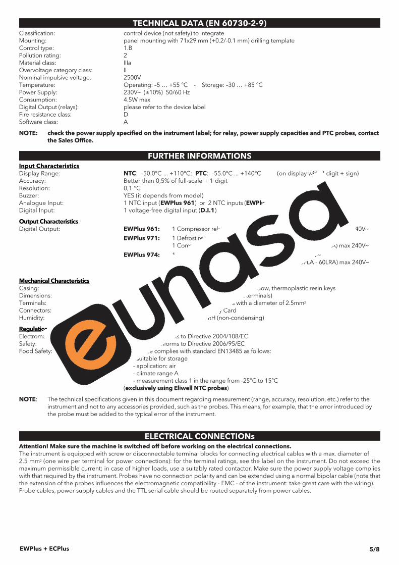
TECHNICAL DATA (EN 60730-2-9)Classification: control device (not safety) to integrateMounting: panel mounting with 71x29 mm (+0.2/-0.1 mm) drilling templateControl type: 1.B Pollution rating: 2 Material class: IIIa Overvoltage category class: IINominal impulsive voltage: 2500VTemperature: Operating: –5 … +55 °C - Storage: –30 … +85 °CPower Supply: 230Va (±10%) 50/60 HzConsumption: 4.5W maxDigital Output (relays): please refer to the device labelFire resistance class: DSoftware class: A
NOTE: check the power supply specified on the instrument label; for relay, power supply capacities and PTC probes, contact the Sales Office.
FURTHER INFORMATIONSInput CharacteristicsDisplay Range: NTC: –50.0°C ... +110°C; PTC: –55.0°C ... +140°C (on display with 3 digit + sign)Accuracy: Better than 0,5% of full-scale + 1 digitResolution: 0,1 °CBuzzer: YES (it depends from model)Analogue Input: 1 NTC input (EWPlus 961) or 2 NTC inputs (EWPlus 971/974)Digital Input: 1 voltage-free digital input (D.I.1)
Output CharacteristicsDigital Output: EWPlus 961: 1 Compressor relay: UL60730 2 Hp (12FLA - 72LRA) max 240Va
EWPlus 971: 1 Defrost relay: N.A. 8(4)A - N.C. 6(3)A max 250Va
1 Compressor relay: UL60730 2 Hp (12FLA - 72LRA) max 240Va
EWPlus 974: 1 Defrost relay: N.A. 8(4)A - N.C. 6(3)A max 250Va
1 Compressor relay: UL60730 1.5 Hp (10FLA - 60LRA) max 240Va
1 Fans relay: 5(2)A max 250Va
Mechanical CharacteristicsCasing: PC+ABS UL94 V-0 resin casing, polycarbonate window, thermoplastic resin keysDimensions: front panel 74x32 mm, depth 59 mm (without terminals)Terminals: screw/disconnectable terminals for cables with a diameter of 2.5mm2
Connectors: TTL for connection of Unicard / Copy CardHumidity: Operating / Storage: 10…90 % RH (non-condensing)
RegulationsElectromagnetic compatibility: The device conforms to Directive 2004/108/ECSafety: The device conforms to Directive 2006/95/ECFood Safety: The device complies with standard EN13485 as follows: - suitable for storage - application: air - climate range A - measurement class 1 in the range from -25°C to 15°C (exclusively using Eliwell NTC probes)
NOTE: The technical specifications given in this document regarding measurement (range, accuracy, resolution, etc.) refer to the instrument and not to any accessories provided, such as the probes. This means, for example, that the error introduced by the probe must be added to the typical error of the instrument.
ELECTRICAL CONNECTIONsAttention! Make sure the machine is switched off before working on the electrical connections.The instrument is equipped with screw or disconnectable terminal blocks for connecting electrical cables with a max. diameter of2.5 mm2 (one wire per terminal for power connections): for the terminal ratings, see the label on the instrument. Do not exceed the maximum permissible current; in case of higher loads, use a suitably rated contactor. Make sure the power supply voltage complies with that required by the instrument. Probes have no connection polarity and can be extended using a normal bipolar cable (note that the extension of the probes influences the electromagnetic compatibility - EMC - of the instrument: take great care with the wiring).Probe cables, power supply cables and the TTL serial cable should be routed separately from power cables.
EWPlus + ECPlus 6/8
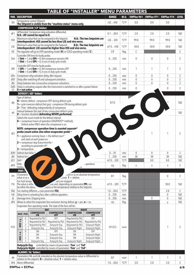
PAR. DESCRIPTION RANGE M.U. EWPlus 961 EWPlus 971 EWPlus 974 LEVEL
SEt Temperature control SEtpoint.The SEtpoint is visible from the "machine status" menu only. LSE ... HSE °C/°F 0.0 0.0 0.0
COMPRESSOR ('CP' folder)
dF1 diFferential. Compressor relay activation differential.N.B.: diF cannot be equal to 0. 0.1 ... 30.0 °C/°F 2.0 2.0 2.0 1&2
HSE Maximum value that can be assigned to the Setpoint. N.B.: The two Setpoints are interdependent: HSE cannot be less than LSE and vice-versa. LSE ... 320 °C/°F 99.0 99.0 99.0 1&2
LSE Minimum value that can be assigned to the Setpoint. N.B.: The two Setpoints are interdependent: LSE cannot be higher than HSE and vice-versa. -67.0 ... HSE °C/°F -50.0 -50.0 -50.0 1&2
HC The regulator will go to HOT operating mode (‘H’) or COLD operating mode (‘C’) C/F flag C 2
OntController ON time for faulty probe.- if Ont = 1 and OFt = 0, the compressor remains ON- if Ont > 0 and OFt > 0, it runs in duty cycle mode.
0 ... 250 min 0 0 0 2
OFtController OFF time for faulty probe.- if OFt = 1 and Ont = 0, the compressor remains OFF- if Ont > 0 and OFt > 0, it runs in duty cycle mode.
0 ... 250 min 1 1 1 2
dOn Compressor relay activation delay after request. 0 ... 250 secs 0 0 0 2dOF Delay after switching off and subsequent activation. 0 ... 250 min 0 0 0 2dbi Delay between two consecutive compressor activations. 0 ... 250 min 0 0 0 2
OdO(!)
Delay in activating outputs after the instrument is switched on or after a power failure.0 = not active. 0 ... 250 min 0 0 0 2
DEFROST ('dEF' folder)
dty
Type of defrost.0= electric defrost - compressor OFF during defrost cycle1= cycle inversion defrost (hot gas) - compressor ON during defrost cycle2= ‘Free’: defrosting independently of compressor
0/1/2 num 0 0 1&2
dit Interval between the start of two consecutive defrost cycles. 0 = function disabled (defrosting NEVER performed) 0 ... 250 hours 6 6 6 1&2
dCt
Selects the count mode for the defrost interval:0 = compressor hours of operation (DIGIFROST® method); Defrost active ONLY when the compressor is on.NOTE: compressor operation time is counted separately from the evaporator probe (count active also when evaporator probe missing or faulty).1 = appliance running hours = the defrost count is always active when the machine is on and starts at each power-on;2 = compressor stop Every time the compressor stops, a defrost cycle is performed according to parameter dtY;3 = temperature.
0/1/2/3 num 1 1 1 2
dOH Defrost start delay time after request. 0 ... 59 min 0 0 0 2dEt Defrost time-out; determines the maximum defrost duration. 1 ... 250 min 30 30 30 1&2dS1 Defrost end temperature (determined by the evaporator probe). -67.0 ... 320 °C/°F 8.0 8.0 1&2
dPO Determines whether the instrument must enter defrost mode (if the temperature measured by the evaporator allows this operation). n = no; y = yes. n/y flag n n n 2
FANS ('FAn' folder)
FPt Characterizes the "FSt" parameter that can be expressed or as an absolute temperature value or as a value related to Setpoint. 0 = absolute; 1 = relative. 0/1 flag 0 2
FStFan lock temperature; if Pb2 > FSt, the fans are stopped.The value is either positive or negative and, depending on parameter FPt, canbe either the absolute temperature or the temperature relative to the Setpoint.
-67.0 ... 320 °C/°F 50.0 1&2
FAd Fan starting differential (see parameter FSt). 1.0 ... 50.0 °C/°F 2.0 2Fdt Delay time in activating fans after a defrost operation. 0 ... 250 min 0 1&2dt drainage time. Dripping time. 0 ... 250 min 0 0 1&2
dFd Allows to select the evaporator fans exclusion during defrost. y = yes; n = no. n/y flag y 1&2
FCO
Evaporator fans operating mode. The state of the fans will be:DAY NIGHT
H42 FCO COMPRESSORON
COMPRESSOROFF
COMPRESSORON
COMPRESSOROFF
H42
= y 0 Regulated by Pb2 OFF Regulated by Pb2 OFF
1 Regulated by Pb2 Regulated by Pb2 Regulated by Pb2 Regulated by Pb22 Regulated by Pb2 Dutycycle Day Regulated by Pb2 Dutycycle Night3 Dutycycle Day Dutycycle Day Dutycycle Night Dutycycle Night
H42
= n 0 ON OFF ON OFF
1 ON Dutycycle Day ON Dutycycle Night2 ON Dutycycle Day ON Dutycycle Night3 Dutycycle Day Dutycycle Day Dutycycle Night Dutycycle Night
Dutycycle Day: controlled by means of parameters “Fon” and “FoF”.Dutycycle Night: controlled by means of parameters “Fnn” and “FnF”.
0/1/2/3 num 1 2
ALARMS ('AL' folder)
Att Parameters HAL and LAL intended as the absolute temperature value or differential in relation to the setpoint. 0 = absolute value; 1 = relative value. 0/1 num 1 1 1 2
AFd Alarm differential. 1.0 ... 50.0 °C/°F 2.0 2.0 2.0 2
TABLE OF "INSTALLER" MENU PARAMETERS
EWPlus + ECPlus 7/8
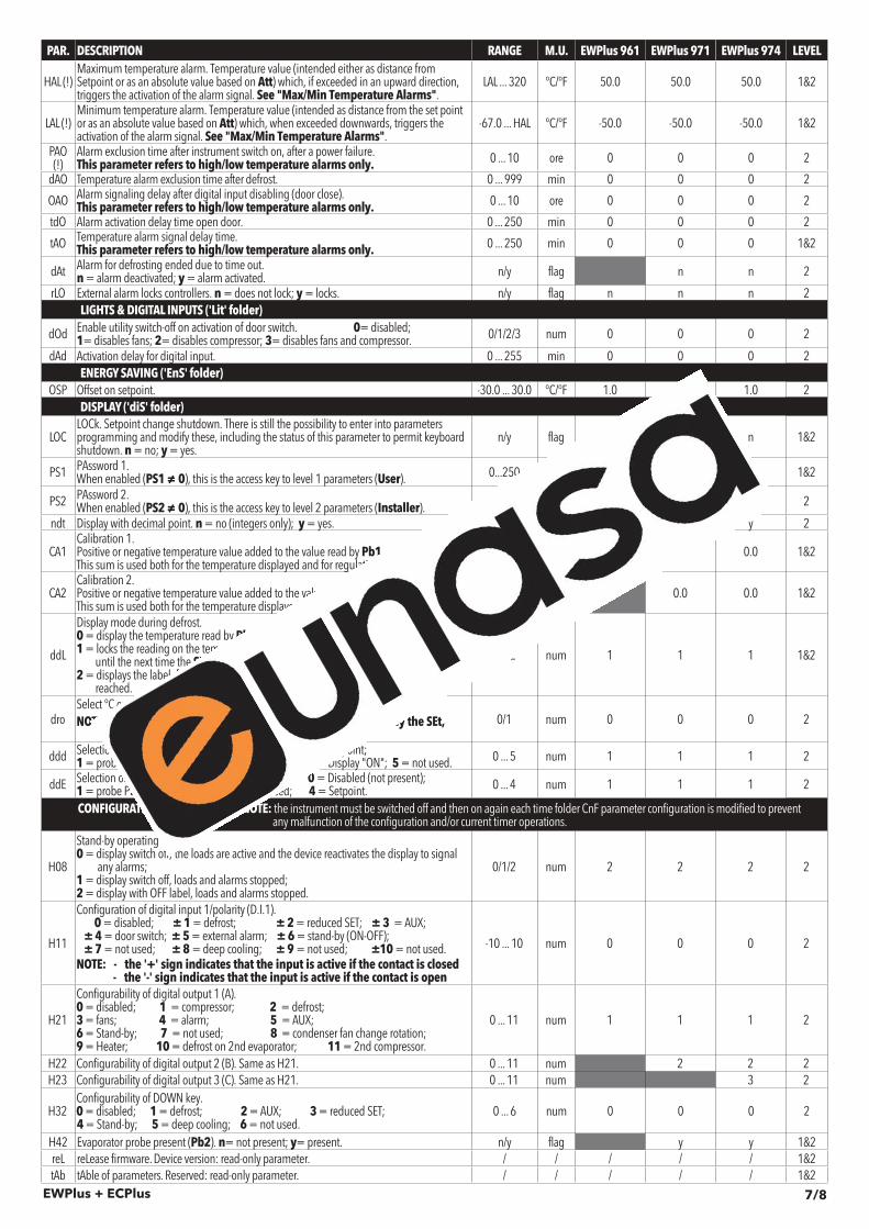
PAR. DESCRIPTION RANGE M.U. EWPlus 961 EWPlus 971 EWPlus 974 LEVEL
HAL (!)Maximum temperature alarm. Temperature value (intended either as distance from Setpoint or as an absolute value based on Att) which, if exceeded in an upward direction, triggers the activation of the alarm signal. See "Max/Min Temperature Alarms".
LAL ... 320 °C/°F 50.0 50.0 50.0 1&2
LAL (!)Minimum temperature alarm. Temperature value (intended as distance from the set point or as an absolute value based on Att) which, when exceeded downwards, triggers the activation of the alarm signal. See "Max/Min Temperature Alarms".
-67.0 ... HAL °C/°F -50.0 -50.0 -50.0 1&2
PAO (!)
Alarm exclusion time after instrument switch on, after a power failure.This parameter refers to high/low temperature alarms only. 0 ... 10 ore 0 0 0 2
dAO Temperature alarm exclusion time after defrost. 0 ... 999 min 0 0 0 2
OAO Alarm signaling delay after digital input disabling (door close).This parameter refers to high/low temperature alarms only. 0 ... 10 ore 0 0 0 2
tdO Alarm activation delay time open door. 0 ... 250 min 0 0 0 2
tAO Temperature alarm signal delay time.This parameter refers to high/low temperature alarms only. 0 ... 250 min 0 0 0 1&2
dAt Alarm for defrosting ended due to time out.n = alarm deactivated; y = alarm activated. n/y flag n n 2
rLO External alarm locks controllers. n = does not lock; y = locks. n/y flag n n n 2 LIGHTS & DIGITAL INPUTS ('Lit' folder)
dOd Enable utility switch-off on activation of door switch. 0= disabled;1= disables fans; 2= disables compressor; 3= disables fans and compressor. 0/1/2/3 num 0 0 0 2
dAd Activation delay for digital input. 0 ... 255 min 0 0 0 2 ENERGY SAVING ('EnS' folder)
OSP Offset on setpoint. -30.0 ... 30.0 °C/°F 1.0 1.0 1.0 2 DISPLAY ('diS' folder)
LOCLOCk. Setpoint change shutdown. There is still the possibility to enter into parameters programming and modify these, including the status of this parameter to permit keyboard shutdown. n = no; y = yes.
n/y flag n n n 1&2
PS1 PAssword 1.When enabled (PS1 ≠ 0), this is the access key to level 1 parameters (User). 0...250 num 0 0 0 1&2
PS2 PAssword 2.When enabled (PS2 ≠ 0), this is the access key to level 2 parameters (Installer). 0...250 num 15 15 15 2
ndt Display with decimal point. n = no (integers only); y = yes. n/y flag y y y 2
CA1Calibration 1.Positive or negative temperature value added to the value read by Pb1.This sum is used both for the temperature displayed and for regulation.
-12.0 ... 12.0 °C/°F 0.0 0.0 0.0 1&2
CA2Calibration 2.Positive or negative temperature value added to the value read by Pb2.This sum is used both for the temperature displayed and for regulation.
-12.0 ... 12.0 °C/°F 0.0 0.0 1&2
ddL
Display mode during defrost.0 = display the temperature read by Pb1;1 = locks the reading on the temperature value read by Pb1 when defrosting starts, and until the next time the SEt value is reached;2 = displays the label deF during defrosting, and until the next time the SEt value is reached.
0/1/2 num 1 1 1 1&2
droSelect °C or °F for displaying the temperature read by probes. 0 = °C, 1 = °F. NOTE: switching between °C and °F or vice-versa DOES NOT modify the SEt, diF values, etc. (e.g. Setpoint=10°C becomes 10°F).
0/1 num 0 0 0 2
ddd Selection of type of value to be displayed. 0 = Setpoint; 1 = probe Pb1; 2 = probe Pb2; 3 = not used; 4 = Display "ON"; 5 = not used. 0 ... 5 num 1 1 1 2
ddE Selection of value to display on ECHO (ECPlus). 0 = Disabled (not present);1 = probe Pb1; 2 = probe Pb2; 3 = not used; 4 = Setpoint. 0 ... 4 num 1 1 1 2
CONFIGURATION ('CnF' folder) - NOTE: the instrument must be switched off and then on again each time folder CnF parameter configuration is modified to prevent any malfunction of the configuration and/or current timer operations.
H08
Stand-by operating mode.0 = display switch off; the loads are active and the device reactivates the display to signal any alarms;1 = display switch off, loads and alarms stopped;2 = display with OFF label, loads and alarms stopped.
0/1/2 num 2 2 2 2
H11
Configuration of digital input 1/polarity (D.I.1). 0 = disabled; ± 1 = defrost; ± 2 = reduced SET; ± 3 = AUX; ± 4 = door switch; ± 5 = external alarm; ± 6 = stand-by (ON-OFF); ± 7 = not used; ± 8 = deep cooling; ± 9 = not used; ±10 = not used.NOTE: - the '+' sign indicates that the input is active if the contact is closed - the '-' sign indicates that the input is active if the contact is open
-10 ... 10 num 0 0 0 2
H21
Configurability of digital output 1 (A).0 = disabled; 1 = compressor; 2 = defrost; 3 = fans; 4 = alarm; 5 = AUX;6 = Stand-by; 7 = not used; 8 = condenser fan change rotation;9 = Heater; 10 = defrost on 2nd evaporator; 11 = 2nd compressor.
0 ... 11 num 1 1 1 2
H22 Configurability of digital output 2 (B). Same as H21. 0 ... 11 num 2 2 2H23 Configurability of digital output 3 (C). Same as H21. 0 ... 11 num 3 2
H32Configurability of DOWN key.0 = disabled; 1 = defrost; 2 = AUX; 3 = reduced SET;4 = Stand-by; 5 = deep cooling; 6 = not used.
0 ... 6 num 0 0 0 2
H42 Evaporator probe present (Pb2). n= not present; y= present. n/y flag y y 1&2reL reLease firmware. Device version: read-only parameter. / / / / / 1&2tAb tAble of parameters. Reserved: read-only parameter. / / / / / 1&2
EWPlus + 8/8
cod. 9IS24266-1 • EWPlus+ECPlus • rel.06/12 • EN
© Eliwell Controls s.r.l. 2012 - All rights reserved.
LIABILITY AND RESIDUAL RISKSELIWELL CONTROLS SRL declines any liability for damage due to: - installation/uses different from those specified and, in particular, not complying with the safety regulations and/or instructions given in this document; - use on panels that do not provide adequate protection against electric shocks, water or dust when assembled; - use on panels allowing access to dangerous parts without the use of tools; - tampering with and/or modifying the product; - installation/use on panels not complying with current standards and regulations.
DISCLAIMERThis document is the exclusive property of ELIWELL CONTROLS SRL and may not be reproduced or circulated unless expressly authorised by ELIWELL CONTROLS SRL itself. Every care has been taken in preparing this document; nevertheless ELIWELL CONTROLSSRL cannot accept liability for any damage resulting from its use.The same applies to any person or company involved in preparing and editing this document.ELIWELL CONTROLS SRL reserves the right to make aesthetic or functional changes at any time without notice.
CONDITIONS OF USEPermitted useFor safety reasons, the instrument must be installed and used according to the instructions supplied and, in particular, parts under dangerous voltages must not be accessible in normal conditions. The device must be adequately protected from water and dust with regard to its application, and must only be accessible using tools (except for the front panel).The device is suitable for use in household refrigeration appliances and/or similar equipment and has been tested for safety aspects in accordance with the harmonised European reference standards.
Improper useAny use other than that expressly permitted is prohibited. The relay contacts provided are of a functional type and subject to failure: any protection devices required by product standards, or suggested by common sense for obvious safety requirements, must be installed externally to the instrument.
PAR. DESCRIPTION RANGE M.U. EWPlus 961 EWPlus 971 EWPlus 974 LEVEL COPY CARD ('Fpr' folder)
UL Upload. Programming parameter transfer from instrument to Copy Card. / / / / /
FrFormat Copy Card. Erase all data contained in the Copy CardATTENTION: If parameter “Fr” is used, the data entered will be permanently lost. This operation cannot be cancelled.
/ / / / /