Embed Size (px)
Citation preview

Technician’s Handbook
This manual is updated as new information and models are released. Visit our website for the latest manual.
www.manitowocfsg.com
America’s Quality Choice in Refrigeration
Beermaster Refrigeration Units
Part Number STH13 9/10
™
STH13_Tech.book Page 1 Wednesday, September 15, 2010 3:20 PM

STH13_Tech.book Page 2 Wednesday, September 15, 2010 3:20 PM
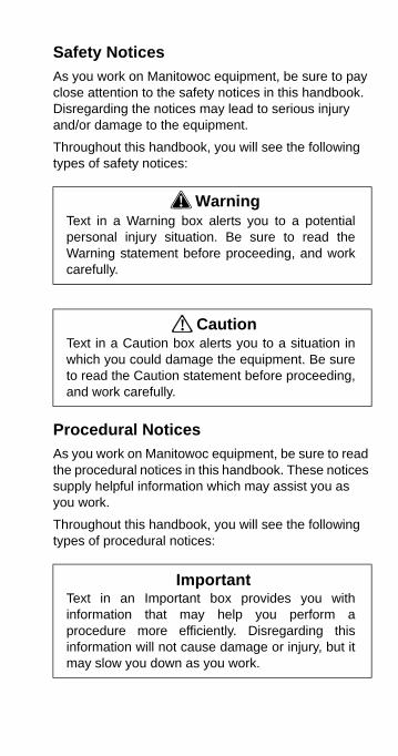
Safety Notices
As you work on Manitowoc equipment, be sure to pay close attention to the safety notices in this handbook. Disregarding the notices may lead to serious injury and/or damage to the equipment.
Throughout this handbook, you will see the following types of safety notices:
Procedural Notices
As you work on Manitowoc equipment, be sure to read the procedural notices in this handbook. These notices supply helpful information which may assist you as you work.
Throughout this handbook, you will see the following types of procedural notices:
! WarningText in a Warning box alerts you to a potentialpersonal injury situation. Be sure to read theWarning statement before proceeding, and workcarefully.
! CautionText in a Caution box alerts you to a situation inwhich you could damage the equipment. Be sureto read the Caution statement before proceeding,and work carefully.
ImportantText in an Important box provides you withinformation that may help you perform aprocedure more efficiently. Disregarding thisinformation will not cause damage or injury, but itmay slow you down as you work.
STH13_Tech.book Page 3 Wednesday, September 15, 2010 3:20 PM
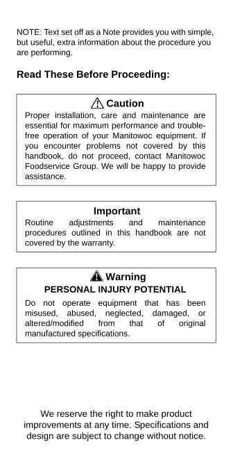
NOTE: Text set off as a Note provides you with simple, but useful, extra information about the procedure you are performing.
Read These Before Proceeding:
! CautionProper installation, care and maintenance areessential for maximum performance and trouble-free operation of your Manitowoc equipment. Ifyou encounter problems not covered by thishandbook, do not proceed, contact ManitowocFoodservice Group. We will be happy to provideassistance.
ImportantRoutine adjustments and maintenanceprocedures outlined in this handbook are notcovered by the warranty.
! WarningPERSONAL INJURY POTENTIAL
Do not operate equipment that has beenmisused, abused, neglected, damaged, oraltered/modified from that of originalmanufactured specifications.
We reserve the right to make product improvements at any time. Specifications and design are subject to change without notice.
STH13_Tech.book Page 4 Wednesday, September 15, 2010 3:20 PM
Part Number STH13 9/10 5
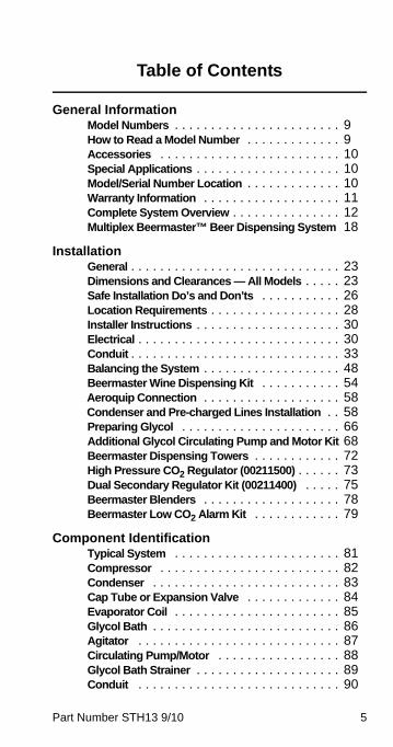
Table of Contents
General InformationModel Numbers . . . . . . . . . . . . . . . . . . . . . . . 9How to Read a Model Number . . . . . . . . . . . . . 9Accessories . . . . . . . . . . . . . . . . . . . . . . . . . 10Special Applications . . . . . . . . . . . . . . . . . . . . 10Model/Serial Number Location . . . . . . . . . . . . . 10Warranty Information . . . . . . . . . . . . . . . . . . . 11Complete System Overview . . . . . . . . . . . . . . . 12Multiplex Beermaster™ Beer Dispensing System 18
InstallationGeneral . . . . . . . . . . . . . . . . . . . . . . . . . . . . . 23Dimensions and Clearances — All Models . . . . . 23Safe Installation Do’s and Don’ts . . . . . . . . . . . 26Location Requirements . . . . . . . . . . . . . . . . . . 28Installer Instructions . . . . . . . . . . . . . . . . . . . . 30Electrical . . . . . . . . . . . . . . . . . . . . . . . . . . . . 30Conduit . . . . . . . . . . . . . . . . . . . . . . . . . . . . . 33Balancing the System . . . . . . . . . . . . . . . . . . . 48Beermaster Wine Dispensing Kit . . . . . . . . . . . 54Aeroquip Connection . . . . . . . . . . . . . . . . . . . 58Condenser and Pre-charged Lines Installation . . 58Preparing Glycol . . . . . . . . . . . . . . . . . . . . . . 66Additional Glycol Circulating Pump and Motor Kit 68Beermaster Dispensing Towers . . . . . . . . . . . . 72High Pressure CO2 Regulator (00211500) . . . . . . 73Dual Secondary Regulator Kit (00211400) . . . . . 75Beermaster Blenders . . . . . . . . . . . . . . . . . . . 78Beermaster Low CO2 Alarm Kit . . . . . . . . . . . . 79
Component IdentificationTypical System . . . . . . . . . . . . . . . . . . . . . . . 81Compressor . . . . . . . . . . . . . . . . . . . . . . . . . 82Condenser . . . . . . . . . . . . . . . . . . . . . . . . . . 83Cap Tube or Expansion Valve . . . . . . . . . . . . . 84Evaporator Coil . . . . . . . . . . . . . . . . . . . . . . . 85Glycol Bath . . . . . . . . . . . . . . . . . . . . . . . . . . 86Agitator . . . . . . . . . . . . . . . . . . . . . . . . . . . . 87Circulating Pump/Motor . . . . . . . . . . . . . . . . . 88Glycol Bath Strainer . . . . . . . . . . . . . . . . . . . . 89Conduit . . . . . . . . . . . . . . . . . . . . . . . . . . . . 90
STH13_Tech.book Page 5 Wednesday, September 15, 2010 3:20 PM
6 Part Number STH13 9/10
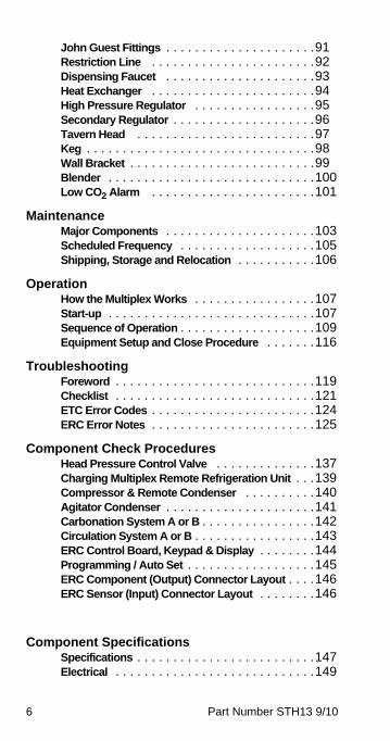
John Guest Fittings . . . . . . . . . . . . . . . . . . . . .91Restriction Line . . . . . . . . . . . . . . . . . . . . . . .92Dispensing Faucet . . . . . . . . . . . . . . . . . . . . .93Heat Exchanger . . . . . . . . . . . . . . . . . . . . . . .94High Pressure Regulator . . . . . . . . . . . . . . . . .95Secondary Regulator . . . . . . . . . . . . . . . . . . . .96Tavern Head . . . . . . . . . . . . . . . . . . . . . . . . .97Keg . . . . . . . . . . . . . . . . . . . . . . . . . . . . . . . .98Wall Bracket . . . . . . . . . . . . . . . . . . . . . . . . . .99Blender . . . . . . . . . . . . . . . . . . . . . . . . . . . . .100Low CO2 Alarm . . . . . . . . . . . . . . . . . . . . . . .101
MaintenanceMajor Components . . . . . . . . . . . . . . . . . . . . .103Scheduled Frequency . . . . . . . . . . . . . . . . . . .105Shipping, Storage and Relocation . . . . . . . . . . .106
OperationHow the Multiplex Works . . . . . . . . . . . . . . . . .107Start-up . . . . . . . . . . . . . . . . . . . . . . . . . . . . .107Sequence of Operation . . . . . . . . . . . . . . . . . . .109Equipment Setup and Close Procedure . . . . . . .116
TroubleshootingForeword . . . . . . . . . . . . . . . . . . . . . . . . . . . .119Checklist . . . . . . . . . . . . . . . . . . . . . . . . . . . .121ETC Error Codes . . . . . . . . . . . . . . . . . . . . . . .124ERC Error Notes . . . . . . . . . . . . . . . . . . . . . . .125
Component Check ProceduresHead Pressure Control Valve . . . . . . . . . . . . . .137Charging Multiplex Remote Refrigeration Unit . . .139Compressor & Remote Condenser . . . . . . . . . .140Agitator Condenser . . . . . . . . . . . . . . . . . . . . .141Carbonation System A or B . . . . . . . . . . . . . . . .142Circulation System A or B . . . . . . . . . . . . . . . . .143ERC Control Board, Keypad & Display . . . . . . . .144Programming / Auto Set . . . . . . . . . . . . . . . . . .145ERC Component (Output) Connector Layout . . . .146ERC Sensor (Input) Connector Layout . . . . . . . .146
Component SpecificationsSpecifications . . . . . . . . . . . . . . . . . . . . . . . . .147Electrical . . . . . . . . . . . . . . . . . . . . . . . . . . . .149
STH13_Tech.book Page 6 Wednesday, September 15, 2010 3:20 PM
Part Number STH13 9/10 7
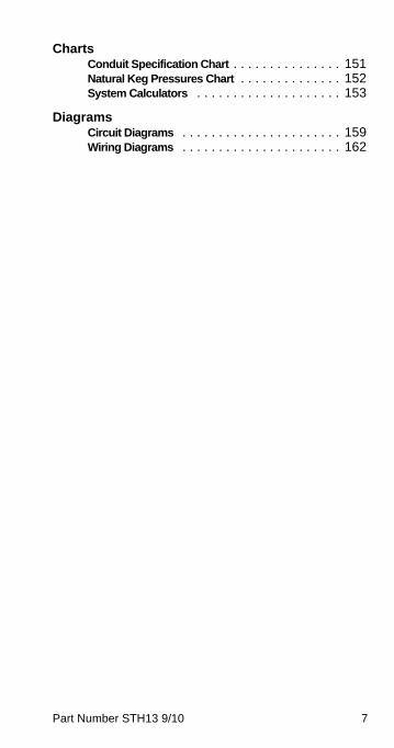
ChartsConduit Specification Chart . . . . . . . . . . . . . . . 151Natural Keg Pressures Chart . . . . . . . . . . . . . . 152System Calculators . . . . . . . . . . . . . . . . . . . . 153
DiagramsCircuit Diagrams . . . . . . . . . . . . . . . . . . . . . . 159Wiring Diagrams . . . . . . . . . . . . . . . . . . . . . . 162
STH13_Tech.book Page 7 Wednesday, September 15, 2010 3:20 PM
8 Part Number STH13 9/10
STH13_Tech.book Page 8 Wednesday, September 15, 2010 3:20 PM
Part Number STH13 9/10 9
General Information
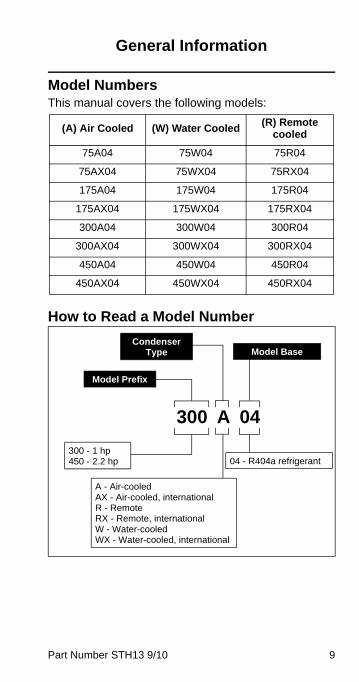
Model NumbersThis manual covers the following models:
How to Read a Model Number
(A) Air Cooled (W) Water Cooled(R) Remote
cooled
75A04 75W04 75R04
75AX04 75WX04 75RX04
175A04 175W04 175R04
175AX04 175WX04 175RX04
300A04 300W04 300R04
300AX04 300WX04 300RX04
450A04 450W04 450R04
450AX04 450WX04 450RX04
04 - R404a refrigerant
Model Prefix
Model Base
300 A 04
A - Air-cooledAX - Air-cooled, internationalR - RemoteRX - Remote, internationalW - Water-cooledWX - Water-cooled, international
Condenser Type
300 - 1 hp450 - 2.2 hp
STH13_Tech.book Page 9 Wednesday, September 15, 2010 3:20 PM
10 Part Number STH13 9/10
AccessoriesDepending on store type and location, various optional equipment may be added to this system. Install and connect any optional equipment in the desired location according to the installation instructions provided with these kits/equipment.
Special Applications
ATTENTION: MARINE INSTALLATIONS
NOTE: This unit must be secured to the vessel during installation. Models with part numbers beginning with the letters TO are NOT marine listed.
OUTDOOR APPLICATIONSTO Multiplex Beverage Recirculating units are approved and listed by Underwriters Laboratories (UL). However they are not UL approved for weather exposure applications. These units must be installed in areas where adequate protection from the elements is provided, all other models are ETL listed.
Model/Serial Number LocationThese numbers are required when requesting information from your local Manitowoc Distributor, service representative, or Manitowoc Foodservice. The model and serial number are listed on the OWNER WARRANTY REGISTRATION CARD. They are also listed on the MODEL/SERIAL NUMBER DECAL affixed to the unit.
! WarningThis unit is for use on vessels over 66 ft (20 m) inlength. This unit must not be installed in theengine space of a gasoline-powered ship.
! WarningPersonal Injury Potential
Do not operate equipment that has been misused,abused, neglected, damaged, or altered/modifiedfrom that of original manufactured specifications.
STH13_Tech.book Page 10 Wednesday, September 15, 2010 3:20 PM
Part Number STH13 9/10 11
Warranty InformationConsult your local distributor for terms and conditions of your warranty. Your warranty specifically excludes all beverage valve brixing, general adjustments, cleaning, accessories and related servicing.
Your warranty card must be returned to activate the warranty on this equipment. If a warranty card is not returned, the warranty period can begin when the equipment leaves the factory.
No equipment may be returned without a written Return Materials Authorization (RMA). Equipment returned without an RMA will be refused at the dock and returned to the sender at the sender’s expense.
Please contact your local distributor for return procedures.
STH13_Tech.book Page 11 Wednesday, September 15, 2010 3:20 PM
12 Part Number STH13 9/10
Complete System Overview
BEER PROPERTIES
General Information
The object of every establishment serving draught beer is to deliver the same high quality of beer to the customer that is delivered to it by the beer distributor. Unfortunately, this objective may be more difficult to achieve than the vendor or proprietor realizes, especially if he is not thoroughly familiar with the relationships that exist between temperature, pressure, and beer delivery systems, all of which have a major effect on the quality of the beer delivered to the customer. A brief discussion of these factors may prove helpful in understanding why a problem exists and what corrective action is required.
Beer is a unique liquid; no two barrels (even of the same brand) are exactly alike. There are large variations between brands. Chemically speaking, beer is a “supersaturated” liquid. Simply stated, beer contains excess carbon dioxide (CO2) which dissipates or “out gasses” if allowed to stand in an open container for a period of time. If this were to happen, the beer would go “flat”. The presence of CO2 gives beer its effervescent quality and distinct flavor. There are several factors that affect the level of carbonation, and therefore the quality and flavor of the beer that is delivered to the customer.
Pressure
Beer is pressurized in the keg by the brewer to his exact specifications, which are optimized for the best possible flavor. For example, under pressurized beer will taste flat and over pressurized beer will taste bitter. It therefore follows that the vendor must carefully balance his system to the beer specifications of the brewer in order to dispense the beer with the best possible flavor to his customers. Failure to do so can result in poor tasting or foamy beer. This is why it is strongly recommended that each keg or beer supply be regulated by its own pressure regulator.
The optimum pressure for most domestic beer, dispensed at normal temperatures and at sea level, is 12 to 14 pounds per square inch (psi) keg pressure.
STH13_Tech.book Page 12 Wednesday, September 15, 2010 3:20 PM
Part Number STH13 9/10 13
Some domestic beers require slightly higher pressure and some imported beers require lower pressure, which explains the need for separate pressure regulators for each brand. This information is readily available from the beer distributor. Areas with higher elevations will require higher keg pressure, specifically one psi for each 2,000 ft (609.6 m) elevation above sea level. This increase in keg pressure is necessary to retain the correct carbonation level in the beer itself, since the carbonation level is a function of the “absolute pressure” and not the difference in pressure between keg and atmospheric (which is the pressure maintained by the pressure regulator on the beer system).
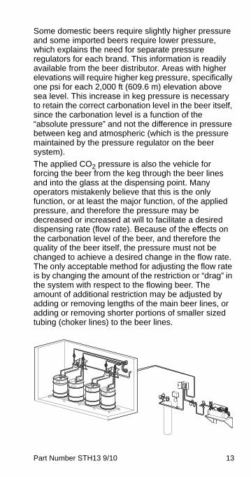
The applied CO2 pressure is also the vehicle for forcing the beer from the keg through the beer lines and into the glass at the dispensing point. Many operators mistakenly believe that this is the only function, or at least the major function, of the applied pressure, and therefore the pressure may be decreased or increased at will to facilitate a desired dispensing rate (flow rate). Because of the effects on the carbonation level of the beer, and therefore the quality of the beer itself, the pressure must not be changed to achieve a desired change in the flow rate. The only acceptable method for adjusting the flow rate is by changing the amount of the restriction or “drag” in the system with respect to the flowing beer. The amount of additional restriction may be adjusted by adding or removing lengths of the main beer lines, or adding or removing shorter portions of smaller sized tubing (choker lines) to the beer lines.
STH13_Tech.book Page 13 Wednesday, September 15, 2010 3:20 PM
14 Part Number STH13 9/10
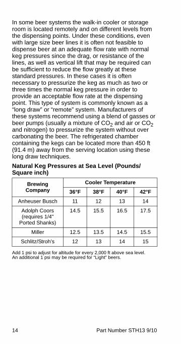
In some beer systems the walk-in cooler or storage room is located remotely and on different levels from the dispensing points. Under these conditions, even with large size beer lines it is often not feasible to dispense beer at an adequate flow rate with normal keg pressures since the drag, or resistance of the lines, as well as vertical lift that may be required can be sufficient to reduce the flow greatly at these standard pressures. In these cases it is often necessary to pressurize the keg as much as two or three times the normal keg pressure in order to provide an acceptable flow rate at the dispensing point. This type of system is commonly known as a “long draw” or “remote” system. Manufacturers of these systems recommend using a blend of gasses or beer pumps (usually a mixture of CO2 and air or CO2 and nitrogen) to pressurize the system without over carbonating the beer. The refrigerated chamber containing the kegs can be located more than 450 ft (91.4 m) away from the serving location using these long draw techniques.
Natural Keg Pressures at Sea Level (Pounds/Square inch)
Add 1 psi to adjust for altitude for every 2,000 ft above sea level. An additional 1 psi may be required for “Light” beers.
Brewing Company
Cooler Temperature
36°F 38°F 40°F 42°F
Anheuser Busch 11 12 13 14
Adolph Coors(requires 1/4"
Ported Shanks)
14.5 15.5 16.5 17.5
Miller 12.5 13.5 14.5 15.5
Schlitz/Stroh’s 12 13 14 15
STH13_Tech.book Page 14 Wednesday, September 15, 2010 3:20 PM
Part Number STH13 9/10 15
TEMPERATUREThe effects of temperature are manifested in several ways. The temperature itself is very significant. A temperature between 36°F (2.2°C) and 38°F (3.3°C) gives the best dispensing results, and is generally favored by most people as providing the best taste. If the beer is cooled below 36°F (2.2°C), more CO2 is absorbed and a greater tendency to out gas may occur when the beer is released to atmospheric pressure by dispensing, thereby producing more foam. The greater absorption of CO2 also imparts a slightly more bitter taste to the beer, which is objectionable to most beer drinkers.
Above 38°F (3.3°C) the CO2 contained in the beer is at a higher energy level and can escape more easily. Therefore out gassing and foaming can occur more readily. This energy level continues to increase at higher temperatures, resulting in a rapid increase in the beer’s tendency to foam.
An increase in temperature in the beer lines or the faucet itself can result in “fracturing” (out gassing) when the beer is dispensed. This generally occurs when un-refrigerated beer lines extend outside of the beer cooler and the ambient temperature surrounding the lines is at a higher temperature than the cooler itself. This can also occur in the beer “tower” at which the faucets are connected when an insufficient amount of coolant is circulated in the tower. The general result is that the first glass dispensed after a delay of several minutes will experience significant fracturing, resulting
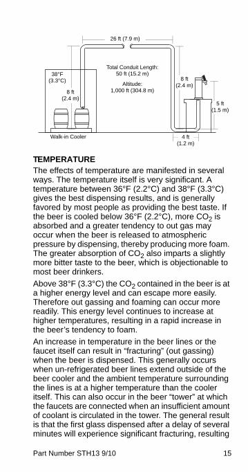
26 ft (7.9 m)
Total Conduit Length:50 ft (15.2 m)
Altitude:1,000 ft (304.8 m)
Walk-in Cooler
38°F(3.3°C)
8 ft(2.4 m)
8 ft(2.4 m)
5 ft(1.5 m)
4 ft(1.2 m)
STH13_Tech.book Page 15 Wednesday, September 15, 2010 3:20 PM
16 Part Number STH13 9/10
in a larger head of foam. To maintain the correct temperature in the tower, care must be taken to ensure that a sufficient amount of coolant is delivered to this area.
THE TEMPERATURE/PRESSURE COMBINATIONSince carbonation of the beer is related to both pressure and temperature, it is important to understand this relationship in order to assure that the highest quality beer product is delivered to the customer. Higher than normal temperatures require higher than normal pressures in order to maintain carbonation. Specifically, in order to maintain proper carbonation, the CO2 pressure must be increased when there is an increase in the beer temperature. For example, a typical American beer that would be properly carbonated at 12 psi (0.8 bar) at a temperature of 38°F (3.3°C) would require an increase in pressure to maintain the same level of carbonation at a temperature of 39°F (4.2°C). Conversely, lowering the temperature requires a corresponding decrease in CO2 pressure to prevent over-carbonation. In actual practice pure CO2 pressures above approximately 16.5 psi (1.1 bar) (at sea level) should be avoided at normal temperature (36°F [2.2°C] to 38°F [3.3°C]) to avoid an unacceptable level of over carbonation which leads to foaming problems. When the pressures above this level are required for good dispensing, the operator should switch to a blend of CO2 and nitrogen for pressurization or beer pumps.
The beer faucet itself is surrounded by normal ambient room air and will warm slightly over a period of several minutes. Since a small amount of beer is trapped behind the faucet, there is a likelihood that this small amount of beer will also warm slightly. The result will be that this trapped beer will fracture and produce foam on the first beer dispensed after an extended idle time. When all of the slightly warmed beer has been depleted from the faucet and the beer line, subsequent beers drawn immediately following the first should produce about the same amount of foam or head, but less than the first beer.
In long draw or remote systems as described above, it is essential to refrigerate the beer lines throughout
STH13_Tech.book Page 16 Wednesday, September 15, 2010 3:20 PM
Part Number STH13 9/10 17
their entire length at about the same temperature as the beer in the cooler. Most manufacturers of these systems agree that it is not possible to adequately refrigerate these lines using cold air over distances greater than about 15 ft (4.6 m). Therefore, these systems utilize a liquid refrigerant line continuously cycling propylene glycol at a temperature below 30°F (-1.1°C) (or other suitable liquid coolant) in physical contact with beer lines and with the overall assembly contained in a flexible, insulated housing. These systems, when properly designed and installed, generally offer the best and most consistent draught beer product. On the other hand, an improperly designed, installed, or maintained system (even a rough or damaged gasket) can produce “shots” of foam, continuous foam, or continuously warm and therefore, foamy beer.
NOTE: A properly designed, installed, and maintained draught dispensing system should deliver beer at 1.75 to 2.0 ounces per second. The beer should be dispensed at 38°F (3.3°C) or less. The beer should flow in a solid, clear column smoothly (neither falling or pushing) from the faucet to the glass.
STH13_Tech.book Page 17 Wednesday, September 15, 2010 3:20 PM
18 Part Number STH13 9/10
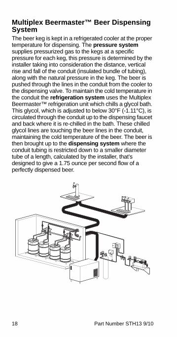
Multiplex Beermaster™ Beer Dispensing SystemThe beer keg is kept in a refrigerated cooler at the proper temperature for dispensing. The pressure system supplies pressurized gas to the kegs at a specific pressure for each keg, this pressure is determined by the installer taking into consideration the distance, vertical rise and fall of the conduit (insulated bundle of tubing), along with the natural pressure in the keg. The beer is pushed through the lines in the conduit from the cooler to the dispensing valve. To maintain the cold temperature in the conduit the refrigeration system uses the Multiplex Beermaster™ refrigeration unit which chills a glycol bath. This glycol, which is adjusted to below 30°F (-1.11°C), is circulated through the conduit up to the dispensing faucet and back where it is re-chilled in the bath. These chilled glycol lines are touching the beer lines in the conduit, maintaining the cold temperature of the beer. The beer is then brought up to the dispensing system where the conduit tubing is restricted down to a smaller diameter tube of a length, calculated by the installer, that’s designed to give a 1.75 ounce per second flow of a perfectly dispensed beer.
STH13_Tech.book Page 18 Wednesday, September 15, 2010 3:20 PM
Part Number STH13 9/10 19
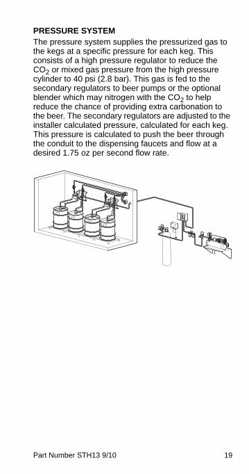
PRESSURE SYSTEM The pressure system supplies the pressurized gas to the kegs at a specific pressure for each keg. This consists of a high pressure regulator to reduce the CO2 or mixed gas pressure from the high pressure cylinder to 40 psi (2.8 bar). This gas is fed to the secondary regulators to beer pumps or the optional blender which may nitrogen with the CO2 to help reduce the chance of providing extra carbonation to the beer. The secondary regulators are adjusted to the installer calculated pressure, calculated for each keg. This pressure is calculated to push the beer through the conduit to the dispensing faucets and flow at a desired 1.75 oz per second flow rate.
STH13_Tech.book Page 19 Wednesday, September 15, 2010 3:20 PM
20 Part Number STH13 9/10
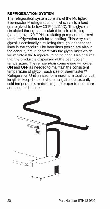
REFRIGERATION SYSTEMThe refrigeration system consists of the Multiplex Beermaster™ refrigeration unit which chills a food grade glycol to below 30°F (-1.11°C). This glycol is circulated through an insulated bundle of tubing (conduit) by a 70 GPH circulating pump and returned to the refrigeration unit for re-chilling. This very cold glycol is continually circulating through independent lines in the conduit. The beer lines (which are also in the conduit) are in contact with the glycol lines which will maintain the temperature of the beer. This ensures that the product is dispensed at the beer cooler temperature. The refrigeration compressor will cycle ON and OFF as needed to maintain the consistent temperature of glycol. Each size of Beermaster™ Refrigeration Unit is rated for a maximum total conduit length to keep the beer dispensing at a consistently cold temperature, maintaining the proper temperature and taste of the beer.
STH13_Tech.book Page 20 Wednesday, September 15, 2010 3:20 PM
Part Number STH13 9/10 21
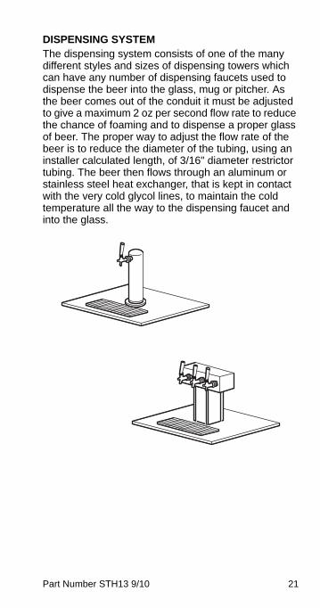
DISPENSING SYSTEMThe dispensing system consists of one of the many different styles and sizes of dispensing towers which can have any number of dispensing faucets used to dispense the beer into the glass, mug or pitcher. As the beer comes out of the conduit it must be adjusted to give a maximum 2 oz per second flow rate to reduce the chance of foaming and to dispense a proper glass of beer. The proper way to adjust the flow rate of the beer is to reduce the diameter of the tubing, using an installer calculated length, of 3/16" diameter restrictor tubing. The beer then flows through an aluminum or stainless steel heat exchanger, that is kept in contact with the very cold glycol lines, to maintain the cold temperature all the way to the dispensing faucet and into the glass.
STH13_Tech.book Page 21 Wednesday, September 15, 2010 3:20 PM
22 Part Number STH13 9/10
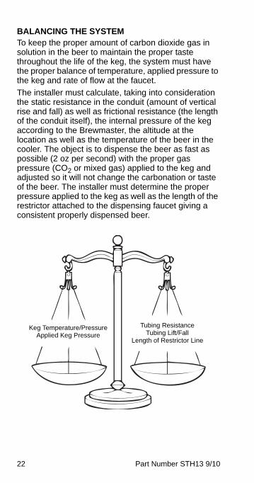
BALANCING THE SYSTEM To keep the proper amount of carbon dioxide gas in solution in the beer to maintain the proper taste throughout the life of the keg, the system must have the proper balance of temperature, applied pressure to the keg and rate of flow at the faucet.
The installer must calculate, taking into consideration the static resistance in the conduit (amount of vertical rise and fall) as well as frictional resistance (the length of the conduit itself), the internal pressure of the keg according to the Brewmaster, the altitude at the location as well as the temperature of the beer in the cooler. The object is to dispense the beer as fast as possible (2 oz per second) with the proper gas pressure (CO2 or mixed gas) applied to the keg and adjusted so it will not change the carbonation or taste of the beer. The installer must determine the proper pressure applied to the keg as well as the length of the restrictor attached to the dispensing faucet giving a consistent properly dispensed beer.
Keg Temperature/Pressure Applied Keg Pressure
Tubing Resistance Tubing Lift/Fall
Length of Restrictor Line
STH13_Tech.book Page 22 Wednesday, September 15, 2010 3:20 PM
Part Number STH13 9/10 23
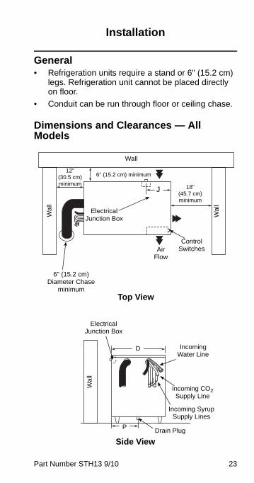
Installation
General• Refrigeration units require a stand or 6" (15.2 cm)
legs. Refrigeration unit cannot be placed directly on floor.
• Conduit can be run through floor or ceiling chase.
Dimensions and Clearances — All Models
Wal
l
6" (15.2 cm)Diameter Chase
minimum
Air Flow
Control Switches
18"(45.7 cm)minimum
J
Electrical Junction Box
6" (15.2 cm) minimum12"
(30.5 cm)minimum
Wa
ll
Wall
Top View
Side View
P
Wa
ll
Electrical Junction Box
Incoming Water Line
Incoming CO2 Supply Line
Incoming Syrup Supply Lines
Drain Plug
D
STH13_Tech.book Page 23 Wednesday, September 15, 2010 3:20 PM
24 Part Number STH13 9/10
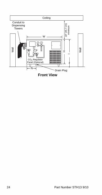
Front View
W
Ceiling
Wa
ll
18"
(45
.7 c
m)
min
imu
mI
H
CO2 Regulator Panel (Optional)
NDrain Plug
Wal
l
Conduit to Dispensing
Towers
STH13_Tech.book Page 24 Wednesday, September 15, 2010 3:20 PM
Part Number STH13 9/10 25
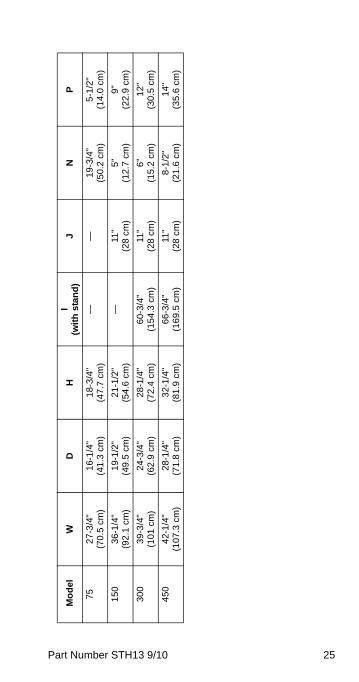
Mo
del
WD
HI
(wit
h s
tan
d)
JN
P
752
7-3
/4"
(70.
5 cm
)1
6-1
/4"
(41
.3 c
m)
18-
3/4
" (4
7.7
cm
)—
—1
9-3
/4"
(50.
2 cm
)5
-1/2
" (1
4.0
cm)
15
03
6-1
/4"
(92.
1 cm
)1
9-1
/2"
(49
.5 c
m)
21-
1/2
" (5
4.6
cm
)—
11"
(28
cm
)5
" (1
2.7
cm)
9"
(22.
9 cm
)
30
03
9-3
/4"
(101
cm
)2
4-3
/4"
(62
.9 c
m)
28-
1/4
" (7
2.4
cm
)6
0-3
/4"
(15
4.3
cm
)11
" (2
8 c
m)
6"
(15.
2 cm
)1
2"
(30.
5 cm
)
45
04
2-1
/4"
(10
7.3
cm
)2
8-1
/4"
(71
.8 c
m)
32-
1/4
" (8
1.9
cm
)6
6-3
/4"
(16
9.5
cm
)11
" (2
8 c
m)
8-1
/2"
(21.
6 cm
)1
4"
(35.
6 cm
)
STH13_Tech.book Page 25 Wednesday, September 15, 2010 3:20 PM
26 Part Number STH13 9/10
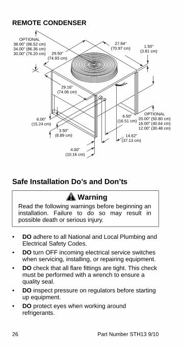
REMOTE CONDENSER
Safe Installation Do’s and Don’ts
• DO adhere to all National and Local Plumbing and Electrical Safety Codes.
• DO turn OFF incoming electrical service switches when servicing, installing, or repairing equipment.
• DO check that all flare fittings are tight. This check must be performed with a wrench to ensure a quality seal.
• DO inspect pressure on regulators before starting up equipment.
• DO protect eyes when working around refrigerants.
! WarningRead the following warnings before beginning aninstallation. Failure to do so may result inpossible death or serious injury.
OPTIONAL38.00" (96.52 cm)34.00" (86.36 cm)30.00" (76.20 cm) 29.50"
(74.93 cm)
29.16"(74.06 cm)
6.00"(15.24 cm)
3.50"(8.89 cm)
4.00"(10.16 cm)
14.62"(37.13 cm)
6.50"(16.51 cm)
OPTIONAL20.00" (50.80 cm)16.00" (40.64 cm)12.00" (30.48 cm)
1.50"(3.81 cm)
27.94"(70.97 cm)
STH13_Tech.book Page 26 Wednesday, September 15, 2010 3:20 PM
Part Number STH13 9/10 27
• DO use caution when handling metal surface edges of all equipment.
• DO handle CO2 cylinders and gauges with care. Secure cylinders properly against abrasion.
• DO store CO2 cylinder(s) in well ventilated areas.
• DO NOT exhaust CO2 gas (example: syrup pump) into an enclosed area, including all types of walk-in coolers, cellars, and closets.
• DO NOT throw or drop a CO2 cylinder. Secure the cylinder(s) in an upright position with a chain.
• DO NOT connect the CO2 cylinder(s) directly to the product container. Doing so will result in an explosion causing possible death or injury. It is best to connect the CO2 cylinder(s) to a regulator(s).
• DO NOT store CO2 cylinders in temperature above 125°F (51.7°C) near furnaces, radiator or sources of heat.
• DO NOT release CO2 gas from old cylinder.
• DO NOT touch refrigeration lines inside units; some may exceed temperatures of 200°F (93.3°C).
NOTE: All utility connections and fixtures must be sized, installed, and maintained in accordance with Federal, State, and Local codes.
STH13_Tech.book Page 27 Wednesday, September 15, 2010 3:20 PM
28 Part Number STH13 9/10
Location RequirementsSelect a location for the refrigeration unit that meets the requirements of the building plans, local codes, and personnel. The unit must be positioned for free airflow as well as for future service. The following requirements must be met:
• Beverage quality CO2 gas (bulk or bottled supply) with a minimum 3/8" (.96 cm) line
NOTE: Refer to serial plate on front of refrigeration unit for voltage and amperage specifications. Make all electrical connections at the junction box located at the top rear of unit. Optional equipment may require additional power supplies.
! WarningCarbon Dioxide (CO2) displaces oxygen.Exposure to a high concentration of CO2 gascauses tremors, which are followed rapidly byloss of consciousness and suffocation. If a CO2gas leak is suspected, particularly in a small area,immediately ventilate the area before repairingthe leak. CO2 lines and pumps must not beinstalled in an enclosed space. An enclosedspace can be a cooler or small room or closet.This may include convenience stores with glassdoor self serve coolers. If you suspect CO2 maybuild up in an area, venting of the BIB pumpsand/or CO2 monitors must be utilized.
STH13_Tech.book Page 28 Wednesday, September 15, 2010 3:20 PM
Part Number STH13 9/10 29
KITCHEN EQUIPMENT INSTALLER REPRESENTATIVE RESPONSIBILITIES
Prior to scheduling Multiplex Equipment installer, the following steps listed below must be completed:
1. Electrical power supply meeting the requirements for the unit to be installed. (See the specification in this section or refer to the unit’s serial plate).
2. CO2 Gas (bulk or bottled supply); minimum 3/8" line.
3. A 120 VAC, 3-wire, 1 Phase, 60 Hz dual wall receptacle for optional electrical equipment (domestic only).
NOTE: Do not schedule the authorized Multiplex Equipment Installer until all of the above have been completed. It will only result in charge-backs to you for the unnecessary trips.
REQUIREMENTS FOR REFRIGERATION UNITS• Conduit can be run through floor or ceiling chase.
• 60°F (15.6°C) minimum and 105°F (40.5°C) maximum operating ambient conditions.
• For indoor installation only.
• Beer supply can be located on stand or floor in a walk-in adjacent to refrigeration unit.
STH13_Tech.book Page 29 Wednesday, September 15, 2010 3:20 PM
30 Part Number STH13 9/10
Installer Instructions
AMBIENT LOCATION REQUIREMENTThis equipment is rated for indoor use only. It will not operate in sub-freezing temperature. In a situation when temperatures drop below freezing, the equipment must be turned off immediately and properly winterized. Contact the manufacturer for winterization process.
Electrical
GENERAL
MINIMUM CIRCUIT AMPACITYThe minimum circuit ampacity is used to help select the wire size of the electrical supply. (Minimum circuit ampacity is not the beverage/ice machine’s running amp load.) The wire size (or gauge) is also dependent upon location, materials used, length of run, etc., so it must be determined by a qualified electrician. See Specifications section.
! WarningAll wiring must conform to local, state andnational codes.
STH13_Tech.book Page 30 Wednesday, September 15, 2010 3:20 PM
Part Number STH13 9/10 31
GROUNDING INSTRUCTIONS
This appliance must be grounded. In the event of malfunction or breakdown, grounding provides a path of least resistance for electric current to reduce the risk of electric shock. This appliance is equipped with a cord having an equipment-grounding conductor and a grounding plug. The plug must be plugged into an appropriate outlet that is properly installed and grounded in accordance with all local codes and ordinances.
! WarningThe unit must be grounded in accordance withnational and local electrical codes.
! WarningImproper connection of the equipment-groundingconductor can result in a risk of electric shock.The conductor with insulation having an outersurface that is green with or without yellow stripesis the equipment grounding conductor. If repair orreplacement of the cord or plug is necessary, donot connect the equipment-grounding conductorto a live terminal. Check with a qualifiedelectrician or serviceman if the groundinginstructions are not completely understood, or ifin doubt as to whether the appliance is properlygrounded. Do not modify the plug provided withthe appliance — if it will not fit the outlet, have aproper outlet installed by a qualified electrician.
STH13_Tech.book Page 31 Wednesday, September 15, 2010 3:20 PM
32 Part Number STH13 9/10
! WarningWhen using electric appliances, basic precautionsmust always be followed, including the following:
a. Read all the instructions before using the appliance.
b. To reduce the risk of injury, close supervision is necessary when an appliance is used near children.
c. Do not contact moving parts.
d. Only use attachments recommended or sold by the manufacturer.
e. Do not use outdoors.
f. For a cord-connected appliance, the following shall be included:
• Do not unplug by pulling on cord. To unplug, grasp the plug, not the cord.
• Unplug from outlet when not in use and before servicing or cleaning.
• Do not operate any appliance with a damaged cord or plug, or after the appliance malfunctions or is dropped or damaged in any manner. Contact the nearest authorized service facility for examination, repair, or electrical or mechanical adjustment.
g. For a permanently connected appliance — Turn the power switch to the off position when the appliance is not in use and before servicing or cleaning.
h. For an appliance with a replaceable lamp — Always unplug before replacing the lamp. Replace the bulb with the same type.
i. For a grounded appliance — Connect to a properly grounded outlet only. See Grounding Instructions.
STH13_Tech.book Page 32 Wednesday, September 15, 2010 3:20 PM
Part Number STH13 9/10 33
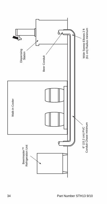
Conduit
FLOOR CHASES Before pulling beer conduit through a floor chase, ensure the floor chase contains the following:
• 6" (15 cm) minimum PVC conduit chase
• Chase openings should extend 6" (15 cm) above floor
• Wide sweep elbows (2 ft [0.6 m] radius minimum)
• Chase must be clean and dry — no foreign materials
STH13_Tech.book Page 33 Wednesday, September 15, 2010 3:20 PM
34 Part Number STH13 9/10
Bee
rmas
ter™
R
efr
ige
ratio
n U
nit
Wal
k-in
Co
ole
r
Dis
pe
nsin
g
Sta
tion
Be
er
Co
ndu
it
6" (
15
.2 c
m)
PV
C
Co
nd
uit C
ha
se m
inim
umW
ide
Sw
ee
p E
lbo
ws
2 ft
(6
1 c
m)
Ra
diu
s m
inim
um
STH13_Tech.book Page 34 Wednesday, September 15, 2010 3:20 PM
Part Number STH13 9/10 35
Pulling Conduit Through Floor Chase
1. Determine the most convenient way of routing conduit, starting at the end which offers adequate room for installation. The conduit installation process requires the assistance of at least two (2) qualified personnel.
2. Route the steel fish tape through chase opening. Push fish tape through entire chase until it appears at opposite end.
3. Locate an appropriate length of rope and tie to end of fish tape (end which was routed through chase in step 2). Approximately 2 ft (0.6 m) from steel fish tape/rope connection, secure a swab to rope (use mop heads or a bundle of rags for swab).
4. Pull end of fish tape from starting point through chase with rope and swab. The swab will clean any construction materials, moisture, or debris that may exist in floor chase. Continue to swab the chase until the swab exits the chase clean and dry.
5. After floor chase has been cleaned, remove steel fish tape and swab from rope. Locate bundle of beer conduit and unspool conduit to allow unrestricted feed during installation process.
6. Locate rope through floor chase opening and connect to proper end of beer conduit.
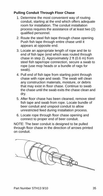
NOTE: The beer conduit is designed to be pulled through floor chase in the direction of arrows printed on conduit.
STH13_Tech.book Page 35 Wednesday, September 15, 2010 3:20 PM
36 Part Number STH13 9/10
7. After rope has been connected, tape end of conduit, including rope, and form conduit end to a point (see figure above). Tape will ensure that no contaminants enter conduit tubes during installation.
8. Place pointed end of the conduit through chase opening. While one person pushes the conduit through chase, another person should be pulling the conduit through the chase with rope at the opposite end.
9. Once the conduit has been routed through the chase, pull enough conduit through the openings to ensure an adequate supply at each end of the chase for connections.
STH13_Tech.book Page 36 Wednesday, September 15, 2010 3:20 PM
Part Number STH13 9/10 37
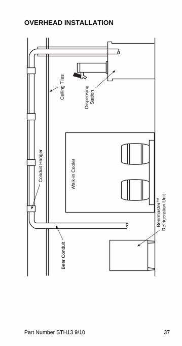
OVERHEAD INSTALLATION
Bee
rmas
ter™
R
efr
iger
atio
n U
nit
Wa
lk-i
n C
oo
ler
Dis
pen
sin
g
Sta
tion
Ce
iling
Tile
s
Co
nd
uit H
an
ger
Be
er
Co
ndu
it
STH13_Tech.book Page 37 Wednesday, September 15, 2010 3:20 PM
38 Part Number STH13 9/10
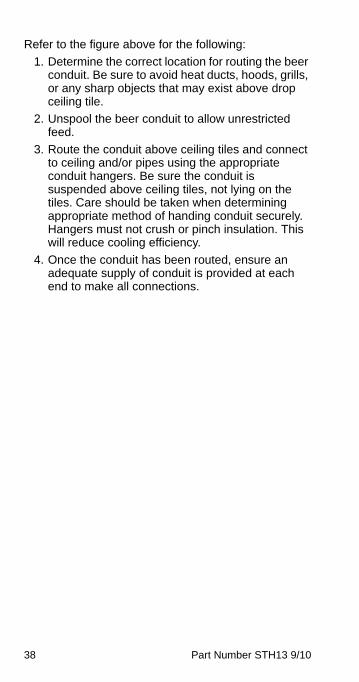
Refer to the figure above for the following:
1. Determine the correct location for routing the beer conduit. Be sure to avoid heat ducts, hoods, grills, or any sharp objects that may exist above drop ceiling tile.
2. Unspool the beer conduit to allow unrestricted feed.
3. Route the conduit above ceiling tiles and connect to ceiling and/or pipes using the appropriate conduit hangers. Be sure the conduit is suspended above ceiling tiles, not lying on the tiles. Care should be taken when determining appropriate method of handing conduit securely. Hangers must not crush or pinch insulation. This will reduce cooling efficiency.
4. Once the conduit has been routed, ensure an adequate supply of conduit is provided at each end to make all connections.
STH13_Tech.book Page 38 Wednesday, September 15, 2010 3:20 PM
Part Number STH13 9/10 39
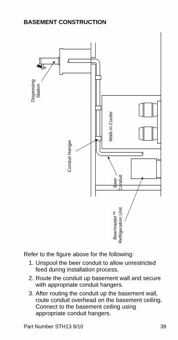
BASEMENT CONSTRUCTION
Refer to the figure above for the following:
1. Unspool the beer conduit to allow unrestricted feed during installation process.
2. Route the conduit up basement wall and secure with appropriate conduit hangers.
3. After routing the conduit up the basement wall, route conduit overhead on the basement ceiling. Connect to the basement ceiling using appropriate conduit hangers.
Bee
rmas
ter™
R
efr
ige
ratio
n U
nit
Wa
lk-i
n C
oo
ler
Dis
pen
sin
g
Sta
tion
Co
nd
uit H
an
ger
Be
er
Co
ndu
it
STH13_Tech.book Page 39 Wednesday, September 15, 2010 3:20 PM
40 Part Number STH13 9/10
4. Once the conduit has been routed, ensure an adequate supply of conduit is on hand to make all connections.
CONNECTING BEER CONDUIT
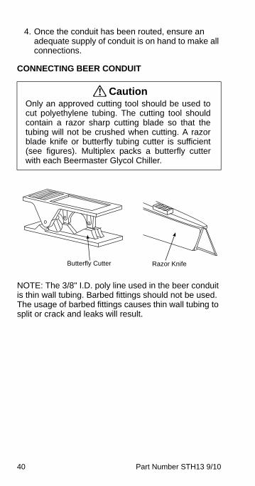
NOTE: The 3/8" I.D. poly line used in the beer conduit is thin wall tubing. Barbed fittings should not be used. The usage of barbed fittings causes thin wall tubing to split or crack and leaks will result.
! CautionOnly an approved cutting tool should be used tocut polyethylene tubing. The cutting tool shouldcontain a razor sharp cutting blade so that thetubing will not be crushed when cutting. A razorblade knife or butterfly tubing cutter is sufficient(see figures). Multiplex packs a butterfly cutterwith each Beermaster Glycol Chiller.
Butterfly Cutter Razor Knife
STH13_Tech.book Page 40 Wednesday, September 15, 2010 3:20 PM
Part Number STH13 9/10 41
Be
erm
aste
r™
Re
frig
era
tion
Un
it
Wal
k-in
Co
ole
r
Dis
pen
sin
g S
tatio
n
Ma
in B
eer
Co
nd
uit -
6”
Min
imu
m D
ia.
Be
er C
on
duit
to W
alk-
in
Coo
ler
STH13_Tech.book Page 41 Wednesday, September 15, 2010 3:20 PM
42 Part Number STH13 9/10
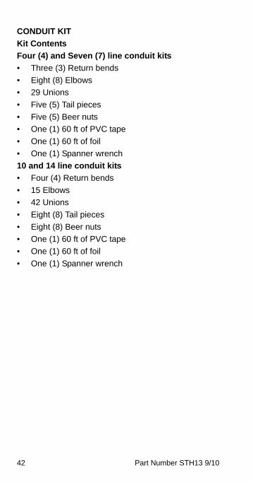
CONDUIT KIT
Kit Contents
Four (4) and Seven (7) line conduit kits
• Three (3) Return bends
• Eight (8) Elbows
• 29 Unions
• Five (5) Tail pieces
• Five (5) Beer nuts
• One (1) 60 ft of PVC tape
• One (1) 60 ft of foil
• One (1) Spanner wrench
10 and 14 line conduit kits
• Four (4) Return bends
• 15 Elbows
• 42 Unions
• Eight (8) Tail pieces
• Eight (8) Beer nuts
• One (1) 60 ft of PVC tape
• One (1) 60 ft of foil
• One (1) Spanner wrench
STH13_Tech.book Page 42 Wednesday, September 15, 2010 3:20 PM
Part Number STH13 9/10 43
INSTALLING THE CONDUIT KIT
Connections Preview
Review the three illustrations under “Circuit Diagrams” in the Diagrams section to determine which best illustrates your particular installation. Consider the following while examining the drawings:
Beer conduits have been designed to achieve the proper cooling of each encased beer line. In order to function properly, you must follow these guidelines:
Up to eight line conduit:
• six beer maximum, one glycol circuit (two lines)
Ten and over line conduit:
• two glycol circuits (four lines)
To ensure colder dispensing temperatures, glycol should flow directly to the dispensing towers before returning to the remote Glycol Chiller Unit. After examining the drawings determine the desired glycol circuit to be achieved and illustrate on paper for referral. Do the same for the assignment of the beer supply lines.
STH13_Tech.book Page 43 Wednesday, September 15, 2010 3:20 PM
44 Part Number STH13 9/10
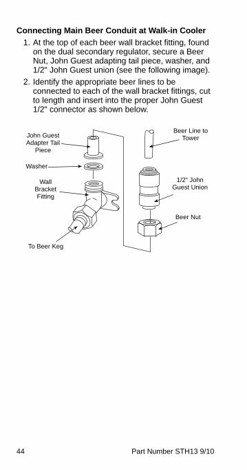
Connecting Main Beer Conduit at Walk-in Cooler
1. At the top of each beer wall bracket fitting, found on the dual secondary regulator, secure a Beer Nut, John Guest adapting tail piece, washer, and 1/2" John Guest union (see the following image).
2. Identify the appropriate beer lines to be connected to each of the wall bracket fittings, cut to length and insert into the proper John Guest 1/2" connector as shown below.
John Guest Adapter Tail
Piece
Washer
Wall Bracket Fitting
To Beer Keg
Beer Nut
Beer Line to Tower
1/2" John Guest Union
STH13_Tech.book Page 44 Wednesday, September 15, 2010 3:20 PM
Part Number STH13 9/10 45
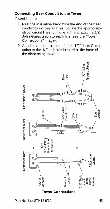
Connecting Beer Conduit to the Tower
Glycol lines in
1. Peel the insulation back from the end of the beer conduit to expose all lines. Locate the appropriate glycol circuit lines, cut to length and attach a 1/2" John Guest union to each line (see the “Tower Connections” image).
2. Attach the opposite end of each 1/2" John Guest union to the 1/2" adapter located at the base of the dispensing tower.
Tower Connections
3/1
6" B
arb
x
1/2
" Jo
hn
G
ues
t A
da
pte
r
1/2
" Jo
hn
Gu
est
Uni
on
1/2"
Joh
n G
uest
Uni
on
Bee
r Li
ne
Be
er
Co
ndu
it
Gly
col
Lin
e
Gly
col
Ma
nifo
ldA
dap
ter
Re
stric
tor
Lin
es
Ad
just
abl
e
Cla
mp
Se
e
“Cal
cula
ting
R
estr
ictio
n”
for
Le
ngth
Dis
pen
ser
Tow
er
Dis
pen
ser
Tow
er
Dis
pens
er T
ower
STH13_Tech.book Page 45 Wednesday, September 15, 2010 3:20 PM
46 Part Number STH13 9/10
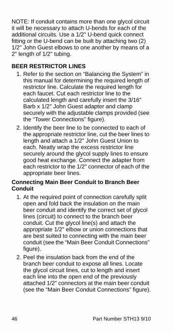
NOTE: If conduit contains more than one glycol circuit it will be necessary to attach U-bends for each of the additional circuits. Use a 1/2" U-bend quick connect fitting or the U-bend can be built by attaching two (2) 1/2" John Guest elbows to one another by means of a 2" length of 1/2" tubing.
BEER RESTRICTOR LINES1. Refer to the section on “Balancing the System” in
this manual for determining the required length of restrictor line. Calculate the required length for each faucet. Cut each restrictor line to the calculated length and carefully insert the 3/16" Barb x 1/2" John Guest adapter and clamp securely with the adjustable clamps provided (see the “Tower Connections” figure).
2. Identify the beer line to be connected to each of the appropriate restrictor line, cut the beer lines to length and attach a 1/2" John Guest Union to each. Neatly wrap the excess restrictor line securely around the glycol supply lines to ensure good heat exchange. Connect the adapter from each restrictor to the 1/2" connector of each of the appropriate beer lines.
Connecting Main Beer Conduit to Branch Beer Conduit
1. At the required point of connection carefully split open and fold back the insulation on the main beer conduit and identify the correct set of glycol lines (circuit) to connect to the branch beer conduit. Cut the glycol line(s) and attach the appropriate 1/2" elbow or union connections that are best suited to connecting with the main beer conduit (see the “Main Beer Conduit Connections” figure).
2. Peel the insulation back from the end of the branch beer conduit to expose all lines. Locate the glycol circuit lines, cut to length and insert each line into the open end of the previously attached 1/2" connectors at the main beer conduit (see the “Main Beer Conduit Connections” figure).
STH13_Tech.book Page 46 Wednesday, September 15, 2010 3:20 PM
Part Number STH13 9/10 47
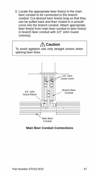
3. Locate the appropriate beer line(s) in the main beer conduit to be connected to the branch conduit. Cut desired beer line(s) long so that they can be pulled back and then routed in a smooth curve into the branch conduit. Attach appropriate beer line(s) from main beer conduit to beer line(s) in branch beer conduit with 1/2" John Guest Union(s).
Main Beer Conduit Connections
! CautionTo avoid agitation use only straight unions whensplicing beer lines.
1/2" John Guest Union
1/2" John Guest Elbow
Branch Beer Conduit
Main Beer Conduit
STH13_Tech.book Page 47 Wednesday, September 15, 2010 3:20 PM
48 Part Number STH13 9/10
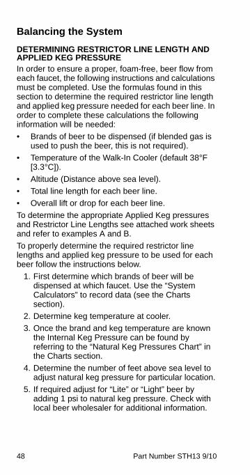
Balancing the System
DETERMINING RESTRICTOR LINE LENGTH AND APPLIED KEG PRESSUREIn order to ensure a proper, foam-free, beer flow from each faucet, the following instructions and calculations must be completed. Use the formulas found in this section to determine the required restrictor line length and applied keg pressure needed for each beer line. In order to complete these calculations the following information will be needed:
• Brands of beer to be dispensed (if blended gas is used to push the beer, this is not required).
• Temperature of the Walk-In Cooler (default 38°F [3.3°C]).
• Altitude (Distance above sea level).
• Total line length for each beer line.
• Overall lift or drop for each beer line.
To determine the appropriate Applied Keg pressures and Restrictor Line Lengths see attached work sheets and refer to examples A and B.
To properly determine the required restrictor line lengths and applied keg pressure to be used for each beer follow the instructions below.
1. First determine which brands of beer will be dispensed at which faucet. Use the “System Calculators” to record data (see the Charts section).
2. Determine keg temperature at cooler.
3. Once the brand and keg temperature are known the Internal Keg Pressure can be found by referring to the “Natural Keg Pressures Chart” in the Charts section.
4. Determine the number of feet above sea level to adjust natural keg pressure for particular location.
5. If required adjust for “Lite” or “Light” beer by adding 1 psi to natural keg pressure. Check with local beer wholesaler for additional information.
STH13_Tech.book Page 48 Wednesday, September 15, 2010 3:20 PM
Part Number STH13 9/10 49
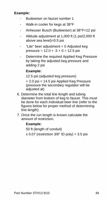
Example:
- Budweiser on faucet number 1
- Walk-in cooler for kegs at 38°F
- Anheuser Busch (Budweiser) at 38°F=12 psi
- Altitude adjustment at 1,000 ft (1 psi/2,000 ft above sea level)=0.5 psi
- “Lite” beer adjustment = 0 Adjusted keg pressure = 12.0 + .5 + 0 = 12.5 psi
- Determine the required Applied Keg Pressure by taking the adjusted keg pressure and adding 2 psi
Example:
12.5 psi (adjusted keg pressure)
+ 2.0 psi = 14.5 psi Applied Keg Pressure (pressure the secondary regulator will be adjusted at)
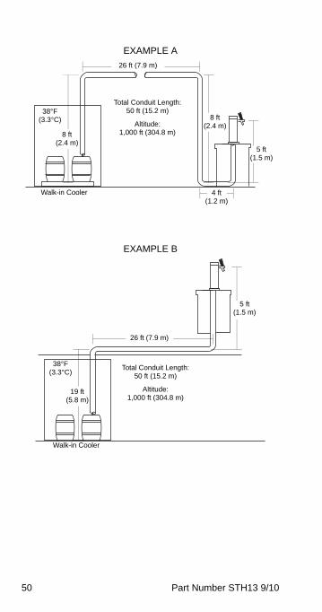
6. Determine the total line length and tubing diameter from bottom of keg to faucet. This must be done for each individual beer line (refer to the figures below for proper method of determining line length).
7. Once the run length is known calculate the amount of restriction.
Example:
50 ft (length of conduit)
x 0.07 (restriction 3/8" ID poly) = 3.5 psi
STH13_Tech.book Page 49 Wednesday, September 15, 2010 3:20 PM
50 Part Number STH13 9/10
EXAMPLE A
EXAMPLE B
26 ft (7.9 m)
Total Conduit Length:50 ft (15.2 m)
Altitude:1,000 ft (304.8 m)
Walk-in Cooler
38°F(3.3°C)
8 ft(2.4 m)
8 ft(2.4 m)
5 ft(1.5 m)
4 ft(1.2 m)
26 ft (7.9 m)
Total Conduit Length:50 ft (15.2 m)
Altitude:1,000 ft (304.8 m)
Walk-in Cooler
38°F(3.3°C)
19 ft(5.8 m)
5 ft(1.5 m)
STH13_Tech.book Page 50 Wednesday, September 15, 2010 3:20 PM
Part Number STH13 9/10 51
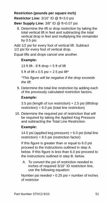
Restriction (pounds per square inch)
Restrictor Line: 3/16" ID @ ft=3.0 psi
Beer Supply Line: 3/8" ID @ ft=0.07 psi
8. Determine the lift or drop restriction by taking the total vertical lift in feet and subtracting the total vertical drop in feet and multiplying the remainder by 0.5 psi.
Add 1/2 psi for every foot of vertical lift. Subtract 1/2 psi for every foot of vertical drop.
Equal lifts and drops cancel one another.
Example:
13 ft lift - 8 ft drop = 5 ft of lift
5 ft of lift x 0.5 psi = 2.5 psi lift*
*This figure will be negative if the drop exceeds the lift.
9. Determine the total line restriction by adding each of the previously calculated restriction factors.
Example:
3.5 psi (length of run restriction) + 2.5 psi (lift/drop restriction) = 6.0 psi (total line restriction)
10. Determine the required psi of restriction that will be required by taking the Applied Keg Pressure and subtracting the Total Line Restriction.
Example:
14.5 psi (applied keg pressure) + 6.0 psi (total line restriction) = 8.5 psi (restriction factor)
If this figure is greater than or equal to 6.0 psi proceed to the instructions outlined in step A. below. If this figure is less than 6.0 psi proceed to the instructions outlined in step B. below.
A. To convert the psi of restriction needed to inches of required 3/16" ID restriction line, use the following equation:
Number psi needed ÷ 0.25 psi = number of inches of restrictor
STH13_Tech.book Page 51 Wednesday, September 15, 2010 3:20 PM
52 Part Number STH13 9/10
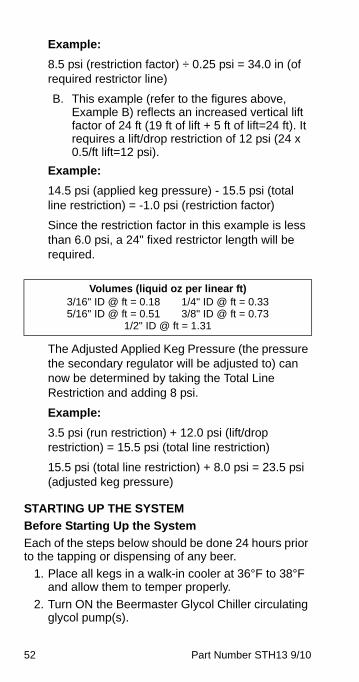
Example:
8.5 psi (restriction factor) ÷ 0.25 psi = 34.0 in (of required restrictor line)
B. This example (refer to the figures above, Example B) reflects an increased vertical lift factor of 24 ft (19 ft of lift + 5 ft of lift=24 ft). It requires a lift/drop restriction of 12 psi (24 x 0.5/ft lift=12 psi).
Example:
14.5 psi (applied keg pressure) - 15.5 psi (total line restriction) = -1.0 psi (restriction factor)
Since the restriction factor in this example is less than 6.0 psi, a 24" fixed restrictor length will be required.
The Adjusted Applied Keg Pressure (the pressure the secondary regulator will be adjusted to) can now be determined by taking the Total Line Restriction and adding 8 psi.
Example:
3.5 psi (run restriction) + 12.0 psi (lift/drop restriction) = 15.5 psi (total line restriction)
15.5 psi (total line restriction) + 8.0 psi = 23.5 psi (adjusted keg pressure)
STARTING UP THE SYSTEM
Before Starting Up the System
Each of the steps below should be done 24 hours prior to the tapping or dispensing of any beer.
1. Place all kegs in a walk-in cooler at 36°F to 38°F and allow them to temper properly.
2. Turn ON the Beermaster Glycol Chiller circulating glycol pump(s).
Volumes (liquid oz per linear ft) 3/16" ID @ ft = 0.18 1/4" ID @ ft = 0.335/16" ID @ ft = 0.51 3/8" ID @ ft = 0.73
1/2" ID @ ft = 1.31
STH13_Tech.book Page 52 Wednesday, September 15, 2010 3:20 PM
Part Number STH13 9/10 53
3. After leak testing all glycol and beer supply lines, wrap the lines firmly with foil (to ensure a good heat exchange) and then insulate all lines; to ensure a minimum of 1" insulation over all areas of exposed beverage line.
4. After glycol has circulated through system for approximately one hour, remove the strainer from the glycol bath. Flush the strainers clean with fresh water and reinstall.
Pressure Setting and Start-up
1. Adjust the primary CO2 regulator to 40 PSI and secure the lock nut.
2. If a blender is utilized proceed with adjustments provided with blender kit.
3. Adjust the secondary regulators. It is recommended that when applied keg pressures exceed 20 PSI the secondary regulators be adjusted 2 PSI below the calculated pressure. If more pressure is required after tapping keg, increase as needed.
4. Tap the kegs and proceed to draw beer from each valve one at a time. Ensure each brand is properly drawing before proceeding to the next. The proper flow rate for beer at each valve is 2 ounces per second. Beer should be flowing clear with a full flow from the dispensing faucet (a considerable amount of dispensing may be needed).
5. Secure all secondary regulator lock nuts and complete the information label, identifying the product and its applied keg pressure for each appropriate regulator.
6. Instruct operator on proper maintenance and operating requirements.
STH13_Tech.book Page 53 Wednesday, September 15, 2010 3:20 PM
54 Part Number STH13 9/10
Beermaster Wine Dispensing KitTo dispense chilled wine through the Beermaster™ system, the following components are required:
• Wine Dispensing Kit (P.N. 00211504)
• Nitrogen Regulator (P.N. 00219381)
• Wine Tank, Stainless Steel with general disconnects
INSTALLING
Single Faucet
1. Select faucet on beer tower for wine and remove metal beer faucet. Replace metal beer faucet with plastic wine faucet.
2. Locate product line connected to this faucet at walk-in cooler. If connected to beer wall bracket, disconnect and remove beer nut, tail piece, and John Guest tube connector.
3. Assemble 1/2" x 3/8" John Guest tube connector, appropriate length of 3/8" O.D. poly, to reach location of wine tank, 3/8" x 1/4" FF John Guest connector, and liquid disconnect.
4. Connect nitrogen regulator to nitrogen tank and connect gas line to regulator outlet.
5. Connect empty wine tank and turn on nitrogen tank. Adjust to 30 PSI and pressurize system to check for leaks.
6. Turn OFF nitrogen and depressurize system. Determine system pressure resistance and reset regulator for desired flow.
Multiple Faucets from Same Tank
In addition to component required for single faucet installation, each additional faucet requires:
• Faucet (P.N. 00211885)
• Tee (P.N. 00210862)
1. Install faucets at desired locations.
2. Install tees at appropriate places in 1/2" O.D. poly wine line.
STH13_Tech.book Page 54 Wednesday, September 15, 2010 3:20 PM
Part Number STH13 9/10 55
POSITIONING OF REFRIGERATION UNITBefore proceeding with installation, verify that all requirements for roof mounted Remote Condenser Units have been satisfied (if applicable). Refer to the instructions on installing the Remote Condenser supplied with the unit.
If the unit is to rest on the floor, locate the four 6" (15.2 cm) adjustable legs (optional). Screw and tighten the legs into the bottom of the refrigeration unit. Set the unit in desired location and adjust legs until the unit is level and sturdy. If the unit is to be mounted on a stand, position stand and secure the unit to stand. If the unit is to be installed on a wall mount bracket, install the wall mount bracket and position the unit on the bracket at this time. Fasten the unit to the bracket with bolts provided.
EQUIPMENT PLACEMENTNOTE: All Refrigeration Units must be mounted on either 6" legs or optional stand.
1. Move the stand/refrigeration unit to the designated area and position it near the wall at a distance of at least 6" (15.2 cm) for air circulation in air-cooled units, or at a distance required by local code.
2. Level the stand/unit by adjusting the leg levelers provide on the legs or stand.
3. If the unit is equipped with optional stand, lift the Refrigeration Unit onto the stand. Position the unit in the center of the stand. Be sure to orientate the drain of the refrigeration unit with the drain access hole of the stand. Secure with 5/8"-11 x 1" bolts supplied in kit, use two bolts diagonally. Schedule the electrician to connect the electrical service if you have not already done so (refer to Electrical Requirements for requirements listed in these instructions).
4. Mount any optional equipment at this time. Follow the installation instructions for each kit required.
STH13_Tech.book Page 55 Wednesday, September 15, 2010 3:20 PM
56 Part Number STH13 9/10
ELECTRICAL CONNECTIONS
NOTE: The electrician must refer to the nameplate and wiring schematic on the refrigeration unit for correct electrical requirements. All wiring must comply with all safety codes. Make sure all refrigeration unit power switches are in the OFF position.
5. Route and connect power supply to leads in the electrical junction box at the top rear of the motor compartment.
NOTE: Be sure to connect ground wire(s) to ground screw located on back panel of junction box.
! CautionMake sure power supply to unit is turned off.
STH13_Tech.book Page 56 Wednesday, September 15, 2010 3:20 PM
Part Number STH13 9/10 57
INSULATING CONNECTIONS1. Make sure all exposed lines are well insulated on
towers to conduit, conduit junctions, refrigeration unit to conduits.
2. To insulate the above, use the leftover conduit sections and tape.
3. Cut the conduit sections to fit snugly over the exposed lines and fittings. A little extra time spent doing a thorough job initially will eliminate a call back in several days to make corrections.
NOTE: Do not inject foam material directly on the connections where the tubing connects to the barb fittings or directly on poly tubing.
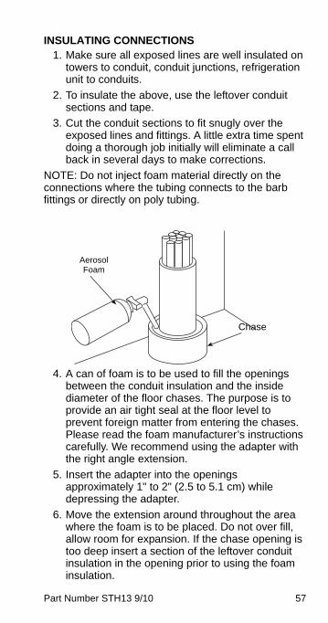
4. A can of foam is to be used to fill the openings between the conduit insulation and the inside diameter of the floor chases. The purpose is to provide an air tight seal at the floor level to prevent foreign matter from entering the chases. Please read the foam manufacturer’s instructions carefully. We recommend using the adapter with the right angle extension.
5. Insert the adapter into the openings approximately 1" to 2" (2.5 to 5.1 cm) while depressing the adapter.
6. Move the extension around throughout the area where the foam is to be placed. Do not over fill, allow room for expansion. If the chase opening is too deep insert a section of the leftover conduit insulation in the opening prior to using the foam insulation.
Aerosol Foam
Chase
STH13_Tech.book Page 57 Wednesday, September 15, 2010 3:20 PM
58 Part Number STH13 9/10
Aeroquip Connection1. Lubricate male half diaphragm and synthetic
rubber seal with refrigerant oil.
2. Thread male coupling to its proper female half by hand to ensure proper mating of threads.
3. Use proper wrenches (on coupling body hex and its union nut) and tighten union nut until coupling bodies “bottom”.
NOTE: You must use a wrench on the body to keep the body from turning while tightening the nut with the second wrench. If the body turns excessively, the piercing seal will be damaged.
4. Use proper wrenches to tighten an additional 1/4 turn (90°). This final 1/4 turn is necessary to ensure the formation of a leak proof joint. Alternately, use a torque wrench to tighten the 1/2" coupling to 40 ft-lbs and 3/8" fitting to 11 ft-lbs.
5. Leak check all your connections. If you detect any leaks, repair and recheck.
Condenser and Pre-charged Lines InstallationBefore proceeding with installation, verify that all requirements for roof mounted remote condenser units (if applicable) have been satisfied. If unit has a remote condenser, refer to the instructions on installing the remote condenser supplied with the condensing unit and refer to the section on installation of remote refrigeration line sets.
ImportantIf you are installing a remote unit, there is arefrigeration king valve located behind thecompressor. This valve must be back seatedprior to starting the compressor. Failure to do sowill short cycle and may damage the compressor.
STH13_Tech.book Page 58 Wednesday, September 15, 2010 3:20 PM
Part Number STH13 9/10 59
MULTIPLEX REMOTE CONDENSER PRE-INSTALLATION REQUIREMENTS
1. Installation and maintenance are to be performed only by qualified refrigeration personnel. These technicians must have EPA certification (USA), are familiar with local codes and regulations, and are experienced with this type of remote refrigeration equipment.
2. As a condition of the warranty, the check, test and start-up procedure must be performed by qualified personnel. Because of possible shipping damage, check both the condensing unit and refrigeration unit(s) for refrigerant leaks.
3. If the refrigeration unit is located on a roll out platform, you must coil up to one round between the back of the stand and the wall. This allows pull out of the refrigeration unit for servicing.
4. If the refrigeration unit is located in a stationary location, you must remove excess refrigeration tubing as described below.
MULTIPLEX PRE-CHARGED REFRIGERATION LINES PRE-INSTALLATION REQUIREMENTS
1. Both the discharge and liquid remote condensing lines must be kept to a minimum distance for maximum performance. All Multiplex systems are capacity rated to 100 ft (30.5 m) tubing distance between the compressor and condenser.
2. Any vertical rise 25 ft (7.62 m) or greater must have a manufactured or installed trap (bend), in the discharge refrigeration line from the compressor to the remote condenser. A trap is necessary for every additional 25 ft (7.62 m) vertical rise. When excessive vertical rise exists, this trap allows oil to reach the condenser and return to the compressor.
3. The easiest method to create a trap is to bend the tubing (smoothly, no kinks) into the trap form.
STH13_Tech.book Page 59 Wednesday, September 15, 2010 3:20 PM
60 Part Number STH13 9/10
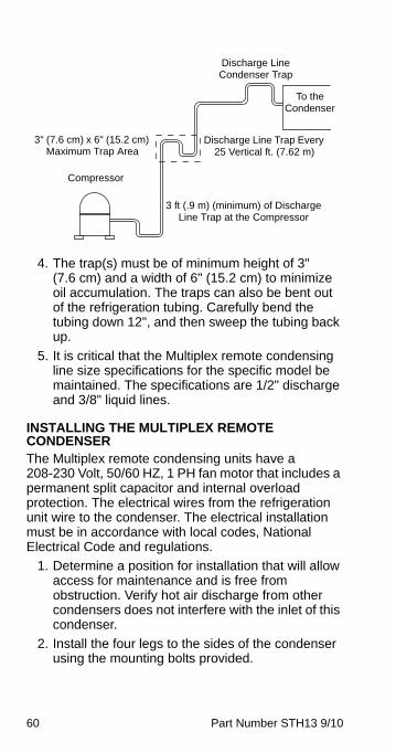
4. The trap(s) must be of minimum height of 3" (7.6 cm) and a width of 6" (15.2 cm) to minimize oil accumulation. The traps can also be bent out of the refrigeration tubing. Carefully bend the tubing down 12", and then sweep the tubing back up.
5. It is critical that the Multiplex remote condensing line size specifications for the specific model be maintained. The specifications are 1/2" discharge and 3/8" liquid lines.
INSTALLING THE MULTIPLEX REMOTE CONDENSERThe Multiplex remote condensing units have a 208-230 Volt, 50/60 HZ, 1 PH fan motor that includes a permanent split capacitor and internal overload protection. The electrical wires from the refrigeration unit wire to the condenser. The electrical installation must be in accordance with local codes, National Electrical Code and regulations.
1. Determine a position for installation that will allow access for maintenance and is free from obstruction. Verify hot air discharge from other condensers does not interfere with the inlet of this condenser.
2. Install the four legs to the sides of the condenser using the mounting bolts provided.
To the Condenser
Discharge Line Trap Every 25 Vertical ft. (7.62 m)
3 ft (.9 m) (minimum) of Discharge Line Trap at the Compressor
Compressor
3" (7.6 cm) x 6" (15.2 cm) Maximum Trap Area
Discharge Line Condenser Trap
STH13_Tech.book Page 60 Wednesday, September 15, 2010 3:20 PM
Part Number STH13 9/10 61
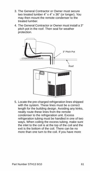
3. The General Contractor or Owner must secure two treated lumber 4" x 4" x 36" (or longer). You may then mount the remote condenser to the treated lumber.
4. The General Contractor or Owner must install a 3" pitch pot in the roof. Then seal for weather protection.
5. Locate the pre-charged refrigeration lines shipped with the system. These lines must be a correct length for the building design. Avoiding any kinks, neatly route these lines from the remote condenser to the refrigeration unit. Excess refrigeration tubing must be handled in one of two ways. When coiling the excess tubing, make sure the inlet to the coil is at the top of the coil and the exit is the bottom of the coil. There can be no more than one turn to the coil. If you have more
3" Pitch Pot
Roof
STH13_Tech.book Page 61 Wednesday, September 15, 2010 3:20 PM
62 Part Number STH13 9/10
tubing, you must cut out the excess before connecting the ends. When cutting the tubing, you must first evacuate the refrigerant (line sets have a positive refrigerant holding charge of two to three ounces). After shortening and welding the tubing together again, you must evacuate the tubing to 250 microns. Then recharge the tubing with 4 ounces of appropriate refrigerant.
CONNECTING THE PRE-CHARGED REFRIGERATION LINESNOTE: Before connecting the pre-charged refrigeration lines, the refrigeration unit must be properly located, leveled, and the water bath filled 1" (2.5 cm) below the installed drain pipe.
1. Attach low side gauge set to service port on each line set to verify positive pressure within the line set.
NOTE: If for any reason the lines are damaged and/or leaking or the lines no longer charged, refer to “How to Re-charge the Line Sets”. If the line set is too long for the application, refer to “How to Shorten the Line Sets”.
2. Always make the connections at the condenser first, using the end of the pre-charged lines with the valve ports.
3. Connect the condenser side with the quick connectors (discharge and liquid) up to condenser. Refer to the section titled “Aeroquip Connection” in these instructions.
4. Connect the refrigeration unit side with the quick connects (discharge and liquid). Make sure to provide a discharge trap at back of refrigeration unit, or bend discharge line down 12" and then up smoothly (no kinks) to provide a trap.
! CautionExcess refrigeration tubing must be properlycared for before being connected to either theremote condenser or the refrigeration unit.
STH13_Tech.book Page 62 Wednesday, September 15, 2010 3:20 PM
Part Number STH13 9/10 63
5. If a low refrigerant charge is detected, recover and recharge the system adding the unit name plate charge.
6. Repair any damages to the line sets before proceeding.
HOW TO SHORTEN THE LINE SETS1. Do not connect either end of the tubing to the
system before everything is set in place. Standard refrigeration practices must be followed regarding the tubing installation.
2. Excess refrigeration tubing must be handled in one of two ways. With a short amount of excess tubing (about 10 feet), you may coil that amount vertically between the condenser and refrigeration unit. When coiling the excess tubing, make sure the inlet to the coil is at the high side of the coil and the exit is the low side of the coil. There can be no more than one turn to the coil. The coil must continue in a downward spiral with no overlaps, similar to a cork screw. If you have more tubing, you must cut out the excess before connecting the ends. When cutting the tubing, you must first evacuate the refrigerant.
3. After shortening the tubing and welding together again, you must vacuum the tubing to 250 microns.
4. Recharge the tubing with the appropriate refrigerant at 4 ounces per length of tubing.
HOW TO RE-CHARGE THE LINE SETSNOTE: This procedure to be used only with damaged or evacuated line sets or with unknown refrigerant type.
1. With the remote condenser lines properly hooked and sealed to the condenser, evacuate to 250 microns for 1 hour, using both Schrader ports on the service line set.
2. For units with model numbers beginning with “SS”, charge the condenser and line set as described here. Add 0.72 oz/ft (0.067 kg/m) of remote line set (one way run distance) plus condenser name plate charge.
STH13_Tech.book Page 63 Wednesday, September 15, 2010 3:20 PM
64 Part Number STH13 9/10
Example:
45 ft of line set
45 x 0.72 oz = 32.4 oz
32.4 oz + condenser charge = Total charge
If the line set and the main refrigeration unit are connected, you must also add that refrigerant charge.
For units with part numbers beginning with “TS”, charge according to the nameplate charge on the refrigeration unit. That is enough refrigerant for up to 100 feet of tubing plus the Multiplex condenser. If you have another brand condenser, please add additional charge for the condenser (example: up to three pounds for a MAC condenser).
3. Connect line sets to the proper discharge and liquid mating connectors on the refrigeration unit using quick connects. Refer to the section titled “Aeroquip Connection” in these instructions.
4. Be sure to observe proper refrigeration techniques when running the line set.
A. The discharge line must loop down at the compressor end to trap liquid from returning to the compressor, unless you are coiling refrigeration tubing behind the unit.
B. The discharge line must loop above discharge connector at the condenser to resist liquid returning to the compressor. Any excess tubing must be removed from the line set before the line set is connected to any equipment.
C. The discharge line must have one P trap every 25 ft (7.6 m) of vertical rise to allow oil to stair-step up to the condenser and eventually return to the compressor.
NOTE: When the connections are made, the seal in the couplings are broken, and if removed for any reason, the refrigerant charge will be lost.
STH13_Tech.book Page 64 Wednesday, September 15, 2010 3:20 PM
Part Number STH13 9/10 65
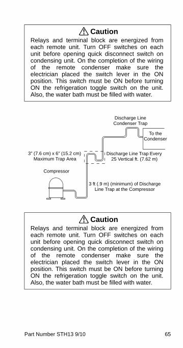
! CautionRelays and terminal block are energized fromeach remote unit. Turn OFF switches on eachunit before opening quick disconnect switch oncondensing unit. On the completion of the wiringof the remote condenser make sure theelectrician placed the switch lever in the ONposition. This switch must be ON before turningON the refrigeration toggle switch on the unit.Also, the water bath must be filled with water.
! CautionRelays and terminal block are energized fromeach remote unit. Turn OFF switches on eachunit before opening quick disconnect switch oncondensing unit. On the completion of the wiringof the remote condenser make sure theelectrician placed the switch lever in the ONposition. This switch must be ON before turningON the refrigeration toggle switch on the unit.Also, the water bath must be filled with water.
To the Condenser
Discharge Line Trap Every 25 Vertical ft. (7.62 m)
3 ft (.9 m) (minimum) of Discharge Line Trap at the Compressor
Compressor
3" (7.6 cm) x 6" (15.2 cm) Maximum Trap Area
Discharge Line Condenser Trap
STH13_Tech.book Page 65 Wednesday, September 15, 2010 3:20 PM
66 Part Number STH13 9/10
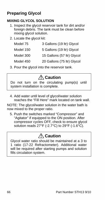
Preparing Glycol
MIXING GLYCOL SOLUTION1. Inspect the glycol reservoir tank for dirt and/or
foreign debris. The tank must be clean before mixing glycol solution.
2. Locate the glycol kit:
Model 75 3 Gallons (19 ltr) Glycol
Model 150 5 Gallons (19 ltr) Glycol
Model 300 15 Gallons (57 ltr) Glycol
Model 450 20 Gallons (75 ltr) Glycol
3. Pour the glycol into the reservoir tank.
4. Add water until level of glycol/water solution reaches the “Fill Here” mark located on tank wall.
NOTE: The glycol/water solution in the water bath is now mixed to the proper ratio.
5. Push the switches marked “Compressor” and “Agitator” if equipped to the ON position. After compressor cycles OFF, check to ensure glycol solution reads 27°F (-2.7°C) to 29°F (-1.6°C).
! CautionDo not turn on the circulating pump(s) untilsystem installation is complete.
! CautionGlycol water ratio should be maintained at a 3 to1 ratio (17-22 Refractometer). Additional waterwill be required after starting pumps and solutionfills circulation system.
STH13_Tech.book Page 66 Wednesday, September 15, 2010 3:20 PM
Part Number STH13 9/10 67
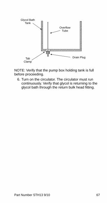
NOTE: Verify that the pump box holding tank is full before proceeding.
6. Turn on the circulator. The circulator must run continuously. Verify that glycol is returning to the glycol bath through the return bulk head fitting.
Drain Plug
Overflow Tube
Glycol Bath Tank
Tab Clamp
STH13_Tech.book Page 67 Wednesday, September 15, 2010 3:20 PM
68 Part Number STH13 9/10
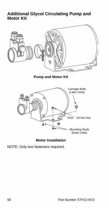
Additional Glycol Circulating Pump and Motor Kit
Pump and Motor Kit
Motor Installation
NOTE: Only two fasteners required.
Carriage Bolts (Later Units)
Mounting Studs (Early Units)
5/16" - 18 Hex Nut
STH13_Tech.book Page 68 Wednesday, September 15, 2010 3:20 PM
Part Number STH13 9/10 69
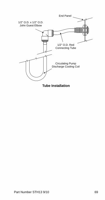
Tube Installation
End Panel
1/2" O.D. x 1/2" O.D. John Guest Elbow
1/2" O.D. Red Connecting Tube
Circulating Pump Discharge Cooling Coil
STH13_Tech.book Page 69 Wednesday, September 15, 2010 3:20 PM
70 Part Number STH13 9/10
INSTALLING THE GLYCOL CIRCULATING PUMP AND MOTOR KIT
1. Remove the lid from the Beermaster refrigeration unit.
2. Install the glycol circulating motor with pump to the motor shelf located in the Beermaster Glycol Unit motor compartment (see “Motor Installation” figure).
NOTE: Motor must be installed with the glycol pump facing away from the glycol bath.
3. Locate the pickup tube and discharge tube assemblies. Slide one piece of insulation over each of the tube assemblies (see “Tube Installation” figure).
4. Attach the pickup tube to the inlet side of the glycol pump making sure the opposite end from the pump is submerged in glycol bath.
5. Attach the discharge tube to the outlet side of the glycol pump.
6. Slide the 1/2" x 1/2" John Guest Elbow, supplied in kit, onto the end of the discharge tube at pump motor assembly.
7. Locate the circulator pump discharge cooling tube, supplied with kit, and insert into the water bath area. Insert straight end of tube into the John Guest elbow fitting as shown.
8. Insert the two 1/2" O.D. John Guest bulkhead unions, supplied in kit, into the pre-punched holes located in the end of the refrigeration unit.
9. Locate the two 1/2" O.D. tube retaining collets, provided in kit, and insert into each of the John Guest bulkhead unions.
10. Insert the free end (bent end) of the circulator pump coil tube into the lower John Guest bulkhead union.
NOTE: Do Not discard the condensation cover over the reservoir tank. It is necessary to prevent excessive condensation from diluting the water-glycol mixture.
STH13_Tech.book Page 70 Wednesday, September 15, 2010 3:20 PM
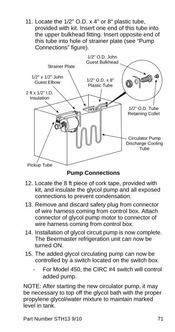
Part Number STH13 9/10 71
11. Locate the 1/2" O.D. x 4" or 8" plastic tube, provided with kit. Insert one end of this tube into the upper bulkhead fitting. Insert opposite end of this tube into hole of strainer plate (see “Pump Connections” figure).
Pump Connections
12. Locate the 8 ft piece of cork tape, provided with kit, and insulate the glycol pump and all exposed connections to prevent condensation.
13. Remove and discard safety plug from connector of wire harness coming from control box. Attach connector of glycol pump motor to connector of wire harness coming from control box.
14. Installation of glycol circuit pump is now complete. The Beermaster refrigeration unit can now be turned ON.
15. The added glycol circulating pump can now be controlled by a switch located on the switch box.
- For Model 450, the CIRC #4 switch will control added pump.
NOTE: After starting the new circulator pump, it may be necessary to top off the glycol bath with the proper propylene glycol/water mixture to maintain marked level in tank.
1/2" O.D. John Guest Bulkhead
1/2" O.D. x 8" Plastic Tube
1/2" O.D. Tube Retaining Collet
Circulator Pump Discharge Cooling
Tube
Pickup Tube
2 ft x 1/2" I.D. Insulation
1/2" x 1/2" John Guest Elbow
Strainer Plate
STH13_Tech.book Page 71 Wednesday, September 15, 2010 3:20 PM
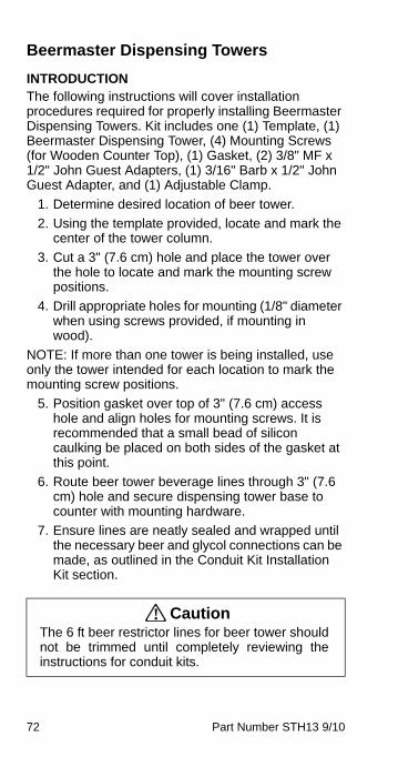
72 Part Number STH13 9/10
Beermaster Dispensing Towers
INTRODUCTIONThe following instructions will cover installation procedures required for properly installing Beermaster Dispensing Towers. Kit includes one (1) Template, (1) Beermaster Dispensing Tower, (4) Mounting Screws (for Wooden Counter Top), (1) Gasket, (2) 3/8" MF x 1/2" John Guest Adapters, (1) 3/16" Barb x 1/2" John Guest Adapter, and (1) Adjustable Clamp.
1. Determine desired location of beer tower.
2. Using the template provided, locate and mark the center of the tower column.
3. Cut a 3" (7.6 cm) hole and place the tower over the hole to locate and mark the mounting screw positions.
4. Drill appropriate holes for mounting (1/8" diameter when using screws provided, if mounting in wood).
NOTE: If more than one tower is being installed, use only the tower intended for each location to mark the mounting screw positions.
5. Position gasket over top of 3" (7.6 cm) access hole and align holes for mounting screws. It is recommended that a small bead of silicon caulking be placed on both sides of the gasket at this point.
6. Route beer tower beverage lines through 3" (7.6 cm) hole and secure dispensing tower base to counter with mounting hardware.
7. Ensure lines are neatly sealed and wrapped until the necessary beer and glycol connections can be made, as outlined in the Conduit Kit Installation Kit section.
! CautionThe 6 ft beer restrictor lines for beer tower shouldnot be trimmed until completely reviewing theinstructions for conduit kits.
STH13_Tech.book Page 72 Wednesday, September 15, 2010 3:20 PM
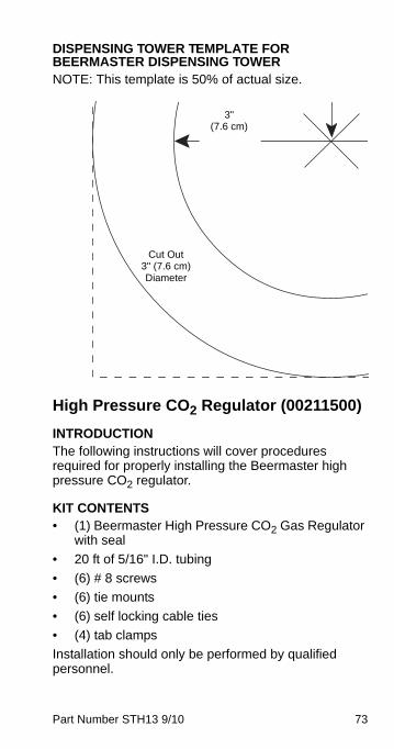
Part Number STH13 9/10 73
DISPENSING TOWER TEMPLATE FOR BEERMASTER DISPENSING TOWERNOTE: This template is 50% of actual size.
High Pressure CO2 Regulator (00211500)
INTRODUCTIONThe following instructions will cover procedures required for properly installing the Beermaster high pressure CO2 regulator.
KIT CONTENTS• (1) Beermaster High Pressure CO2 Gas Regulator
with seal
• 20 ft of 5/16" I.D. tubing
• (6) # 8 screws
• (6) tie mounts
• (6) self locking cable ties
• (4) tab clamps
Installation should only be performed by qualified personnel.
3"(7.6 cm)
Cut Out 3" (7.6 cm) Diameter
STH13_Tech.book Page 73 Wednesday, September 15, 2010 3:20 PM
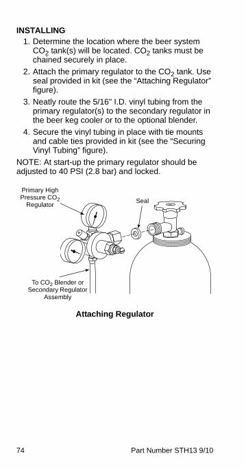
74 Part Number STH13 9/10
INSTALLING1. Determine the location where the beer system
CO2 tank(s) will be located. CO2 tanks must be chained securely in place.
2. Attach the primary regulator to the CO2 tank. Use seal provided in kit (see the “Attaching Regulator” figure).
3. Neatly route the 5/16" I.D. vinyl tubing from the primary regulator(s) to the secondary regulator in the beer keg cooler or to the optional blender.
4. Secure the vinyl tubing in place with tie mounts and cable ties provided in kit (see the “Securing Vinyl Tubing” figure).
NOTE: At start-up the primary regulator should be adjusted to 40 PSI (2.8 bar) and locked.
Attaching Regulator
Primary High Pressure CO2
Regulator
To CO2 Blender or Secondary Regulator
Assembly
Seal
STH13_Tech.book Page 74 Wednesday, September 15, 2010 3:20 PM
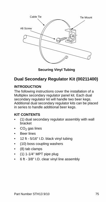
Part Number STH13 9/10 75
Securing Vinyl Tubing
Dual Secondary Regulator Kit (00211400)
INTRODUCTIONThe following instructions cover the installation of a Multiplex secondary regulator panel kit. Each dual secondary regulator kit will handle two beer kegs. Additional dual secondary regulator kits can be placed in series to handle additional beer kegs.
KIT CONTENTS• (1) dual secondary regulator assembly with wall
bracket
• CO2 gas lines
• Beer lines
• 12 ft - 5/16" I.D. black vinyl tubing
• (10) boss coupling washers
• (8) tab clamps
• (1) 1-1/4" MPT pipe plug
• 6 ft - 3/8" I.D. clear vinyl line assembly
Tie MountCable Tie
#8 Screw
STH13_Tech.book Page 75 Wednesday, September 15, 2010 3:20 PM
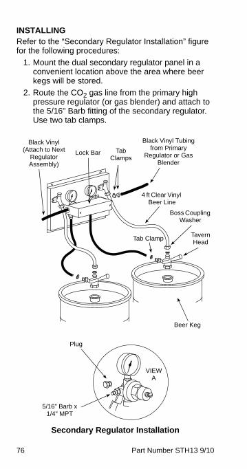
76 Part Number STH13 9/10
INSTALLINGRefer to the “Secondary Regulator Installation” figure for the following procedures:
1. Mount the dual secondary regulator panel in a convenient location above the area where beer kegs will be stored.
2. Route the CO2 gas line from the primary high pressure regulator (or gas blender) and attach to the 5/16" Barb fitting of the secondary regulator. Use two tab clamps.
Secondary Regulator Installation
Beer Keg
Black Vinyl Tubing from Primary
Regulator or Gas Blender
Tab Clamps
5/16" Barb x 1/4" MPT
VIEW A
Plug
Black Vinyl (Attach to Next
Regulator Assembly)
Lock Bar
Tab Clamp
Boss Coupling Washer
4 ft Clear Vinyl Beer Line
Tavern Head
STH13_Tech.book Page 76 Wednesday, September 15, 2010 3:20 PM
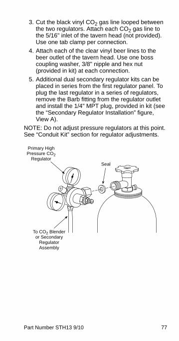
Part Number STH13 9/10 77
3. Cut the black vinyl CO2 gas line looped between the two regulators. Attach each CO2 gas line to the 5/16" inlet of the tavern head (not provided). Use one tab clamp per connection.
4. Attach each of the clear vinyl beer lines to the beer outlet of the tavern head. Use one boss coupling washer, 3/8" nipple and hex nut (provided in kit) at each connection.
5. Additional dual secondary regulator kits can be placed in series from the first regulator panel. To plug the last regulator in a series of regulators, remove the Barb fitting from the regulator outlet and install the 1/4" MPT plug, provided in kit (see the “Secondary Regulator Installation” figure, View A).
NOTE: Do not adjust pressure regulators at this point. See “Conduit Kit” section for regulator adjustments.
Primary High Pressure CO2
Regulator
To CO2 Blender or Secondary
Regulator Assembly
Seal
STH13_Tech.book Page 77 Wednesday, September 15, 2010 3:20 PM
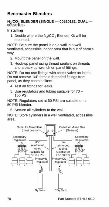
78 Part Number STH13 9/10
Beermaster Blenders
N2/CO2 BLENDER (SINGLE — 00520182, DUAL — 00520183)
Installing
1. Decide where the N2/CO2 Blender Kit will be mounted.
NOTE: Be sure the panel is on a wall in a well ventilated, accessible indoor area that is out of harm’s way.
2. Mount the panel on the wall.
3. Hook-up panel using thread sealant on threads and a back-up wrench on panel fittings.
NOTE: Do not use fittings with check valve on inlets. Do not remove 1/4" female threaded fittings from panel, as they contain filters.
4. Test all fittings for leaks.
5. Use regulators and tubing suitable for 70 – 150 PSI.
NOTE: Regulators set at 50 PSI are suitable on a 50 PSI blender.
6. Secure all cylinders to the wall.
NOTE: Store cylinders in a well ventilated, accessible area.
Outlet for Mixed Gas (most beers)
Outlet for Mixed Gas (Guiness)
Secondary Regulators
Use reinforced
tubing suitable for 70-150 PSI
Primary CO2 Regulator
Primary N2 Regulator
Use reinforced
tubing suitable for 70-150 PSI
Secondary Regulators
N2 Tank CO2 Tank
STH13_Tech.book Page 78 Wednesday, September 15, 2010 3:20 PM
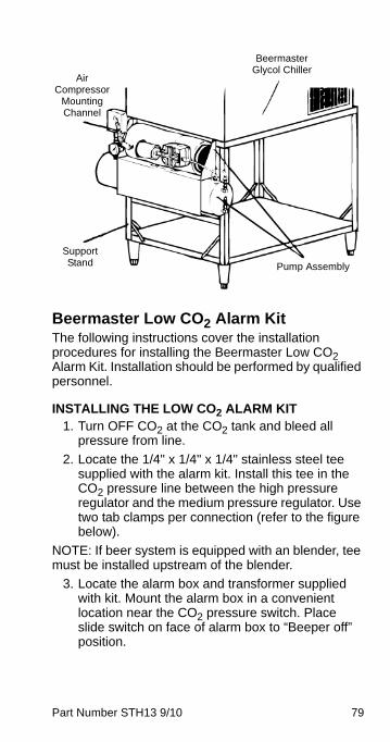
Part Number STH13 9/10 79
Beermaster Low CO2 Alarm KitThe following instructions cover the installation procedures for installing the Beermaster Low CO2 Alarm Kit. Installation should be performed by qualified personnel.
INSTALLING THE LOW CO2 ALARM KIT1. Turn OFF CO2 at the CO2 tank and bleed all
pressure from line.
2. Locate the 1/4" x 1/4" x 1/4" stainless steel tee supplied with the alarm kit. Install this tee in the CO2 pressure line between the high pressure regulator and the medium pressure regulator. Use two tab clamps per connection (refer to the figure below).
NOTE: If beer system is equipped with an blender, tee must be installed upstream of the blender.
3. Locate the alarm box and transformer supplied with kit. Mount the alarm box in a convenient location near the CO2 pressure switch. Place slide switch on face of alarm box to “Beeper off” position.
Beermaster Glycol Chiller
Pump Assembly
Air Compressor
Mounting Channel
Support Stand
STH13_Tech.book Page 79 Wednesday, September 15, 2010 3:20 PM
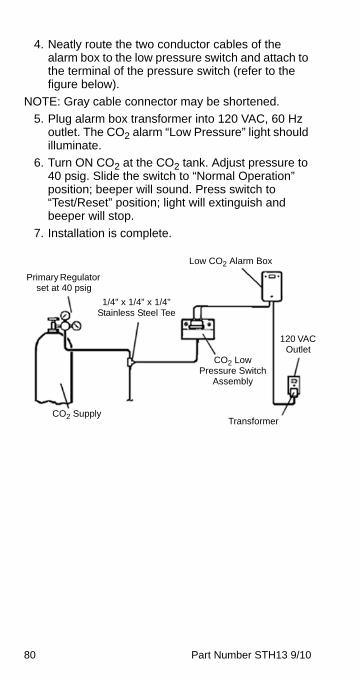
80 Part Number STH13 9/10
4. Neatly route the two conductor cables of the alarm box to the low pressure switch and attach to the terminal of the pressure switch (refer to the figure below).
NOTE: Gray cable connector may be shortened.
5. Plug alarm box transformer into 120 VAC, 60 Hz outlet. The CO2 alarm “Low Pressure” light should illuminate.
6. Turn ON CO2 at the CO2 tank. Adjust pressure to 40 psig. Slide the switch to “Normal Operation” position; beeper will sound. Press switch to “Test/Reset” position; light will extinguish and beeper will stop.
7. Installation is complete.
CO2 Supply
CO2 Low Pressure Switch
Assembly
1/4" x 1/4" x 1/4" Stainless Steel Tee
Low CO2 Alarm Box
Primary Regulator set at 40 psig
120 VAC Outlet
Transformer
STH13_Tech.book Page 80 Wednesday, September 15, 2010 3:20 PM
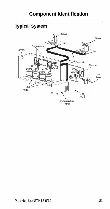
Part Number STH13 9/10 81
Component Identification
Typical System
N2 Tank
CO2 Tank
CO2 Alarm
Refrigeration Unit
Kegs
Cooler
Regulators
Tower
Conduit
Tower
Blender
STH13_Tech.book Page 81 Wednesday, September 15, 2010 3:20 PM
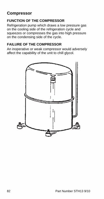
82 Part Number STH13 9/10
Compressor
FUNCTION OF THE COMPRESSORRefrigeration pump which draws a low pressure gas on the cooling side of the refrigeration cycle and squeezes or compresses the gas into high pressure on the condensing side of the cycle.
FAILURE OF THE COMPRESSORAn inoperative or weak compressor would adversely affect the capability of the unit to chill glycol.
STH13_Tech.book Page 82 Wednesday, September 15, 2010 3:20 PM
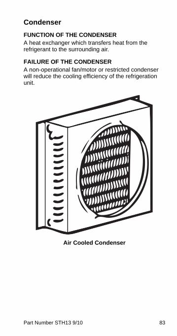
Part Number STH13 9/10 83
Condenser
FUNCTION OF THE CONDENSER A heat exchanger which transfers heat from the refrigerant to the surrounding air.
FAILURE OF THE CONDENSER A non-operational fan/motor or restricted condenser will reduce the cooling efficiency of the refrigeration unit.
Air Cooled Condenser
STH13_Tech.book Page 83 Wednesday, September 15, 2010 3:20 PM
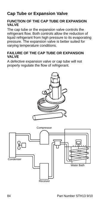
84 Part Number STH13 9/10
Cap Tube or Expansion Valve
FUNCTION OF THE CAP TUBE OR EXPANSION VALVE The cap tube or the expansion valve controls the refrigerant flow. Both controls allow the reduction of liquid refrigerant from high pressure to its evaporating pressure. The expansion valve is better suited for varying temperature conditions.
FAILURE OF THE CAP TUBE OR EXPANSION VALVE A defective expansion valve or cap tube will not properly regulate the flow of refrigerant.
Compressor
Condenser
Water Bath
Receiver
STH13_Tech.book Page 84 Wednesday, September 15, 2010 3:20 PM
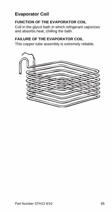
Part Number STH13 9/10 85
Evaporator Coil
FUNCTION OF THE EVAPORATOR COIL Coil in the glycol bath in which refrigerant vaporizes and absorbs heat, chilling the bath.
FAILURE OF THE EVAPORATOR COIL This copper tube assembly is extremely reliable.
STH13_Tech.book Page 85 Wednesday, September 15, 2010 3:20 PM
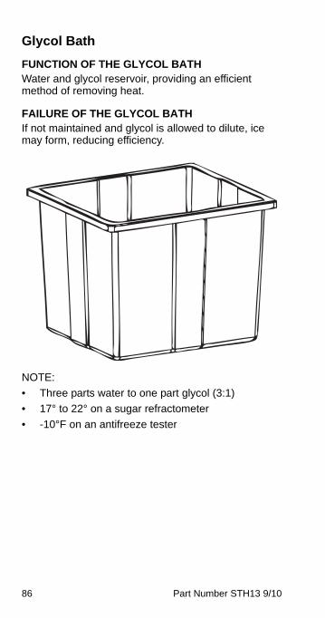
86 Part Number STH13 9/10
Glycol Bath
FUNCTION OF THE GLYCOL BATH Water and glycol reservoir, providing an efficient method of removing heat.
FAILURE OF THE GLYCOL BATH If not maintained and glycol is allowed to dilute, ice may form, reducing efficiency.
NOTE:
• Three parts water to one part glycol (3:1)
• 17° to 22° on a sugar refractometer
• -10°F on an antifreeze tester
STH13_Tech.book Page 86 Wednesday, September 15, 2010 3:20 PM
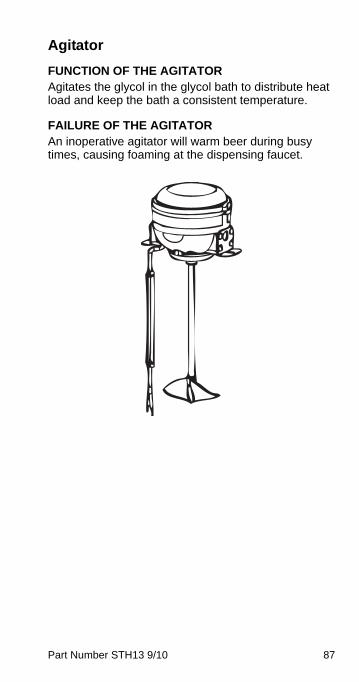
Part Number STH13 9/10 87
Agitator
FUNCTION OF THE AGITATOR Agitates the glycol in the glycol bath to distribute heat load and keep the bath a consistent temperature.
FAILURE OF THE AGITATOR An inoperative agitator will warm beer during busy times, causing foaming at the dispensing faucet.
STH13_Tech.book Page 87 Wednesday, September 15, 2010 3:20 PM
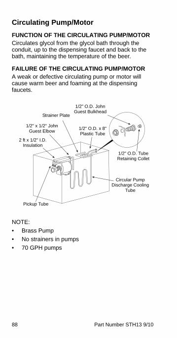
88 Part Number STH13 9/10
Circulating Pump/Motor
FUNCTION OF THE CIRCULATING PUMP/MOTOR Circulates glycol from the glycol bath through the conduit, up to the dispensing faucet and back to the bath, maintaining the temperature of the beer.
FAILURE OF THE CIRCULATING PUMP/MOTOR A weak or defective circulating pump or motor will cause warm beer and foaming at the dispensing faucets.
NOTE:
• Brass Pump
• No strainers in pumps
• 70 GPH pumps
Strainer Plate
1/2" O.D. John Guest Bulkhead
1/2" O.D. Tube Retaining Collet
Circular Pump Discharge Cooling
Tube
2 ft x 1/2" I.D. Insulation
1/2" x 1/2" John Guest Elbow
1/2" O.D. x 8" Plastic Tube
Pickup Tube
STH13_Tech.book Page 88 Wednesday, September 15, 2010 3:20 PM
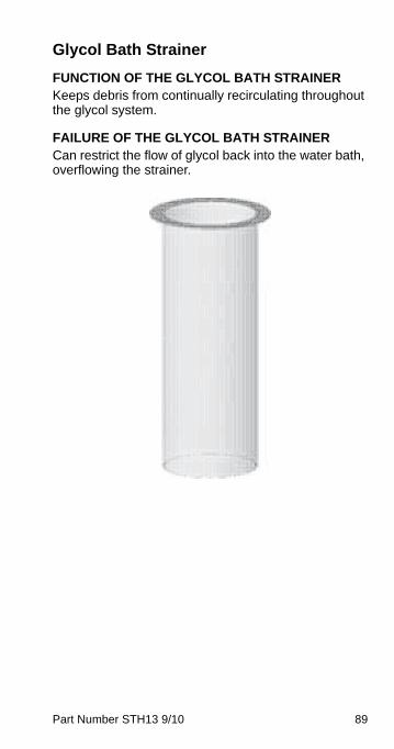
Part Number STH13 9/10 89
Glycol Bath Strainer
FUNCTION OF THE GLYCOL BATH STRAINER Keeps debris from continually recirculating throughout the glycol system.
FAILURE OF THE GLYCOL BATH STRAINER Can restrict the flow of glycol back into the water bath, overflowing the strainer.
STH13_Tech.book Page 89 Wednesday, September 15, 2010 3:20 PM
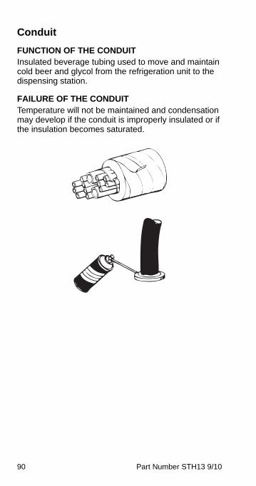
90 Part Number STH13 9/10
Conduit
FUNCTION OF THE CONDUIT Insulated beverage tubing used to move and maintain cold beer and glycol from the refrigeration unit to the dispensing station.
FAILURE OF THE CONDUIT Temperature will not be maintained and condensation may develop if the conduit is improperly insulated or if the insulation becomes saturated.
STH13_Tech.book Page 90 Wednesday, September 15, 2010 3:20 PM
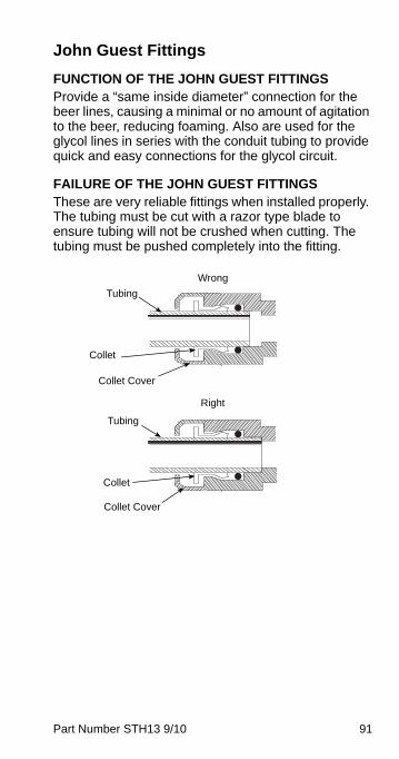
Part Number STH13 9/10 91
John Guest Fittings
FUNCTION OF THE JOHN GUEST FITTINGS Provide a “same inside diameter” connection for the beer lines, causing a minimal or no amount of agitation to the beer, reducing foaming. Also are used for the glycol lines in series with the conduit tubing to provide quick and easy connections for the glycol circuit.
FAILURE OF THE JOHN GUEST FITTINGS These are very reliable fittings when installed properly. The tubing must be cut with a razor type blade to ensure tubing will not be crushed when cutting. The tubing must be pushed completely into the fitting.
Collet
Collet Cover
Wrong
Right
Tubing
Collet
Collet Cover
Tubing
STH13_Tech.book Page 91 Wednesday, September 15, 2010 3:20 PM
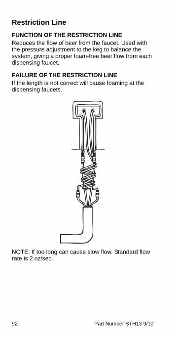
92 Part Number STH13 9/10
Restriction Line
FUNCTION OF THE RESTRICTION LINE Reduces the flow of beer from the faucet. Used with the pressure adjustment to the keg to balance the system, giving a proper foam-free beer flow from each dispensing faucet.
FAILURE OF THE RESTRICTION LINE If the length is not correct will cause foaming at the dispensing faucets.
NOTE: If too long can cause slow flow. Standard flow rate is 2 oz/sec.
STH13_Tech.book Page 92 Wednesday, September 15, 2010 3:20 PM
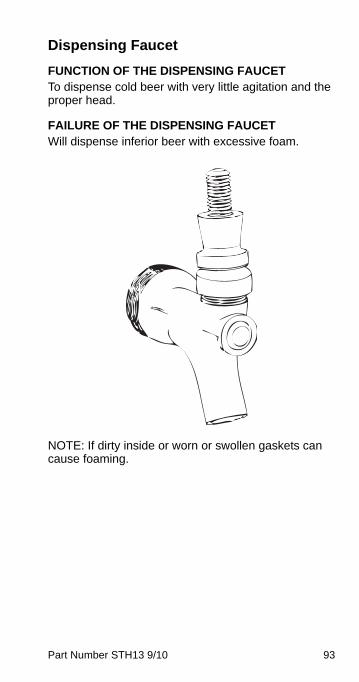
Part Number STH13 9/10 93
Dispensing Faucet
FUNCTION OF THE DISPENSING FAUCET To dispense cold beer with very little agitation and the proper head.
FAILURE OF THE DISPENSING FAUCET Will dispense inferior beer with excessive foam.
NOTE: If dirty inside or worn or swollen gaskets can cause foaming.
STH13_Tech.book Page 93 Wednesday, September 15, 2010 3:20 PM
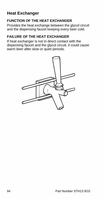
94 Part Number STH13 9/10
Heat Exchanger
FUNCTION OF THE HEAT EXCHANGER Provides the heat exchange between the glycol circuit and the dispensing faucet keeping every beer cold.
FAILURE OF THE HEAT EXCHANGER If heat exchanger is not in direct contact with the dispensing faucet and the glycol circuit, it could cause warm beer after slow or quiet periods.
STH13_Tech.book Page 94 Wednesday, September 15, 2010 3:20 PM
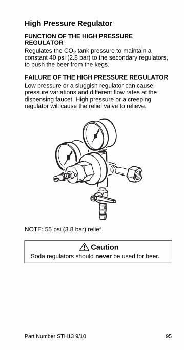
Part Number STH13 9/10 95
High Pressure Regulator
FUNCTION OF THE HIGH PRESSURE REGULATOR Regulates the CO2 tank pressure to maintain a constant 40 psi (2.8 bar) to the secondary regulators, to push the beer from the kegs.
FAILURE OF THE HIGH PRESSURE REGULATOR Low pressure or a sluggish regulator can cause pressure variations and different flow rates at the dispensing faucet. High pressure or a creeping regulator will cause the relief valve to relieve.
NOTE: 55 psi (3.8 bar) relief
! CautionSoda regulators should never be used for beer.
STH13_Tech.book Page 95 Wednesday, September 15, 2010 3:20 PM
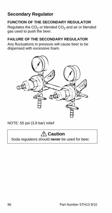
96 Part Number STH13 9/10
Secondary Regulator
FUNCTION OF THE SECONDARY REGULATOR Regulates the CO2 or blended CO2 and air or blended gas used to push the beer.
FAILURE OF THE SECONDARY REGULATOR Any fluctuations in pressure will cause beer to be dispensed with excessive foam.
NOTE: 55 psi (3.8 bar) relief
! CautionSoda regulators should never be used for beer.
STH13_Tech.book Page 96 Wednesday, September 15, 2010 3:20 PM
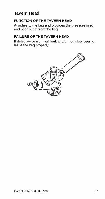
Part Number STH13 9/10 97
Tavern Head
FUNCTION OF THE TAVERN HEADAttaches to the keg and provides the pressure inlet and beer outlet from the keg.
FAILURE OF THE TAVERN HEADIf defective or worn will leak and/or not allow beer to leave the keg properly.
STH13_Tech.book Page 97 Wednesday, September 15, 2010 3:20 PM
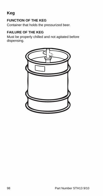
98 Part Number STH13 9/10
Keg
FUNCTION OF THE KEG Container that holds the pressurized beer.
FAILURE OF THE KEG Must be properly chilled and not agitated before dispensing.
STH13_Tech.book Page 98 Wednesday, September 15, 2010 3:20 PM
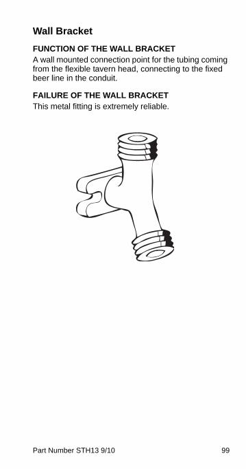
Part Number STH13 9/10 99
Wall Bracket
FUNCTION OF THE WALL BRACKET A wall mounted connection point for the tubing coming from the flexible tavern head, connecting to the fixed beer line in the conduit.
FAILURE OF THE WALL BRACKETThis metal fitting is extremely reliable.
STH13_Tech.book Page 99 Wednesday, September 15, 2010 3:20 PM
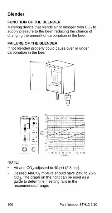
100 Part Number STH13 9/10
Blender
FUNCTION OF THE BLENDER Metering device that blends air or nitrogen with CO2 to supply pressure to the beer, reducing the chance of changing the amount of carbonation in the beer.
FAILURE OF THE BLENDER If not blended properly could cause over or under carbonation in the beer.
NOTE:
• Air and CO2 adjusted to 40 psi (2.8 bar).
• Desired Air/CO2 mixture should have 23% to 26% CO2. The graph on the right can be used as a guide to determine if setting falls in the recommended range.
26%
23%
GPM Air40 41 42 43 44 45 46 47 48 49 50
GPM CO2
20
19
18
17
16
15
14
13
12
11
10
STH13_Tech.book Page 100 Wednesday, September 15, 2010 3:20 PM
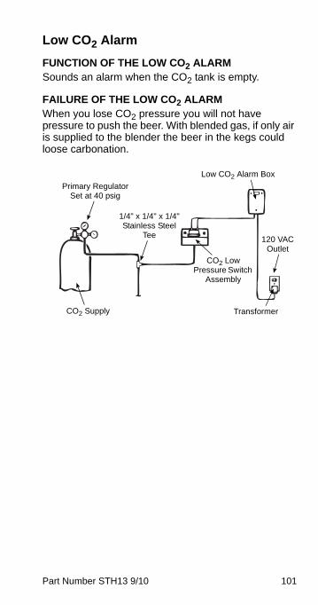
Part Number STH13 9/10 101
Low CO2 Alarm
FUNCTION OF THE LOW CO2 ALARMSounds an alarm when the CO2 tank is empty.
FAILURE OF THE LOW CO2 ALARMWhen you lose CO2 pressure you will not have pressure to push the beer. With blended gas, if only air is supplied to the blender the beer in the kegs could loose carbonation.
Primary Regulator Set at 40 psig
Low CO2 Alarm Box
1/4" x 1/4" x 1/4" Stainless Steel
Tee
CO2 Low Pressure Switch
Assembly
120 VAC Outlet
TransformerCO2 Supply
STH13_Tech.book Page 101 Wednesday, September 15, 2010 3:20 PM
102 Part Number STH13 9/10
This Page Intentionally Left Blank
STH13_Tech.book Page 102 Wednesday, September 15, 2010 3:20 PM
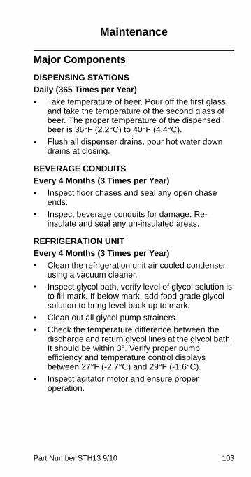
Part Number STH13 9/10 103
Maintenance
Major Components
DISPENSING STATIONS
Daily (365 Times per Year)
• Take temperature of beer. Pour off the first glass and take the temperature of the second glass of beer. The proper temperature of the dispensed beer is 36°F (2.2°C) to 40°F (4.4°C).
• Flush all dispenser drains, pour hot water down drains at closing.
BEVERAGE CONDUITS
Every 4 Months (3 Times per Year)
• Inspect floor chases and seal any open chase ends.
• Inspect beverage conduits for damage. Re-insulate and seal any un-insulated areas.
REFRIGERATION UNIT
Every 4 Months (3 Times per Year)
• Clean the refrigeration unit air cooled condenser using a vacuum cleaner.
• Inspect glycol bath, verify level of glycol solution is to fill mark. If below mark, add food grade glycol solution to bring level back up to mark.
• Clean out all glycol pump strainers.
• Check the temperature difference between the discharge and return glycol lines at the glycol bath. It should be within 3°. Verify proper pump efficiency and temperature control displays between 27°F (-2.7°C) and 29°F (-1.6°C).
• Inspect agitator motor and ensure proper operation.
STH13_Tech.book Page 103 Wednesday, September 15, 2010 3:20 PM
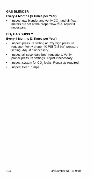
104 Part Number STH13 9/10
GAS BLENDER
Every 4 Months (3 Times per Year)
• Inspect gas blender and verify CO2 and air flow meters are set at the proper flow rate. Adjust if necessary.
CO2 GAS SUPPLY
Every 4 Months (3 Times per Year)
• Inspect pressure setting at CO2 high pressure regulator. Verify proper 40 PSI (2.8 bar) pressure setting. Adjust if necessary.
• Inspect all secondary beer regulators. Verify proper pressure settings. Adjust if necessary.
• Inspect system for CO2 leaks. Repair as required.
• Inspect Beer Pumps.
STH13_Tech.book Page 104 Wednesday, September 15, 2010 3:20 PM
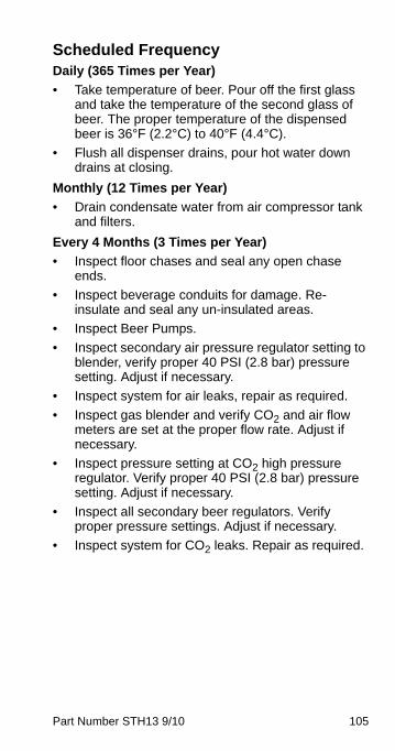
Part Number STH13 9/10 105
Scheduled FrequencyDaily (365 Times per Year)
• Take temperature of beer. Pour off the first glass and take the temperature of the second glass of beer. The proper temperature of the dispensed beer is 36°F (2.2°C) to 40°F (4.4°C).
• Flush all dispenser drains, pour hot water down drains at closing.
Monthly (12 Times per Year)
• Drain condensate water from air compressor tank and filters.
Every 4 Months (3 Times per Year)
• Inspect floor chases and seal any open chase ends.
• Inspect beverage conduits for damage. Re-insulate and seal any un-insulated areas.
• Inspect Beer Pumps.
• Inspect secondary air pressure regulator setting to blender, verify proper 40 PSI (2.8 bar) pressure setting. Adjust if necessary.
• Inspect system for air leaks, repair as required.
• Inspect gas blender and verify CO2 and air flow meters are set at the proper flow rate. Adjust if necessary.
• Inspect pressure setting at CO2 high pressure regulator. Verify proper 40 PSI (2.8 bar) pressure setting. Adjust if necessary.
• Inspect all secondary beer regulators. Verify proper pressure settings. Adjust if necessary.
• Inspect system for CO2 leaks. Repair as required.
STH13_Tech.book Page 105 Wednesday, September 15, 2010 3:20 PM
106 Part Number STH13 9/10
Shipping, Storage and Relocation
! CautionBefore shipping, storing, or relocating this unit,beer systems must be sanitized. After sanitizing,all liquids (sanitizing solution and water) must bepurged from the unit. A freezing environmentcauses residual sanitizing solution or waterremaining inside the unit to freeze, resulting indamage to internal components.
STH13_Tech.book Page 106 Wednesday, September 15, 2010 3:20 PM
Part Number STH13 9/10 107
Operation
How the Multiplex WorksThe refrigeration units are remote refrigeration units that derive their peak capacity from the water/glycol bath. A tower is used to dispense the beer at the desired location. Conduit (an insulated bundle of tubing) connects the refrigeration unit and kegs of beer to the tower. The conduit has the beer and glycol lines wrapped together and the glycol is circulated to keep the beer in the conduit lines cold. The refrigeration system is controlled by a sensing bulb located on an adjustable bracket in the glycol bath. Depending on the setpoint of the temperature control, the refrigeration system cycles ON and OFF as the temperature of the glycol bath changes.
Start-up
PLACING EQUIPMENT IN OPERATIONBefore placing equipment in operation, verify that all requirements for roof mounted Remote Condenser Units (if applicable) have been satisfied. Refer to the instructions on installing the Remote Condenser.
UNITS WITH ROCKER SWITCHES (ETC CONTROLS)
1. Fill the refrigeration unit bath tank with (3:1) water/glycol mix to within 1/2" (1.27 cm) of the top of the overflow tube.
2. Turn on the rocker switch labeled “Refrigeration” to begin cooling the glycol and energize the agitator motor in the glycol bath.
3. The water/glycol bath will reach it’s operating temperature within 2 to 4 hours.
4. If optional CO2/N2 Control Panel has been installed, refer to the installation instructions for operation and testing the circuits for leaks.
5. All circuits must be checked for leaks and possible cross circuits before turning ON.
STH13_Tech.book Page 107 Wednesday, September 15, 2010 3:20 PM
108 Part Number STH13 9/10
6. Turn on the rocker switches for the circulating pumps.
7. Add glycol/water mix as needed to maintain correct bath level.
Units with Touch Pad (ERC Controls)
NOTE: These units have part numbers that end with “E” and only applies to these units.
1. Fill the refrigeration unit bath tank with (3:1) water/glycol mix to within 1/2" (1.27 cm) of the top of the overflow tube.
2. Press “Comp/Agit” to begin chilling the water/glycol bath.
3. The water/glycol bath will reach its operating temperature within 2 to 4 hours.
4. If optional CO2/N2 Control Panel has been installed, refer to the installation instructions for operation and testing the circuits for leaks.
5. All circuits must be checked for leaks and possible cross circuits before turning ON.
NOTE: All pumps on a beer unit are factory programmed as circulating pumps.
CIRC A CIRC 1
CIRC B CIRC 2
CARB B CIRC 3
CARB A CIRC 4
6. In a beer unit temperature control is factory set to come on at 27°F (off at 29°F, 2°F differential)
STH13_Tech.book Page 108 Wednesday, September 15, 2010 3:20 PM
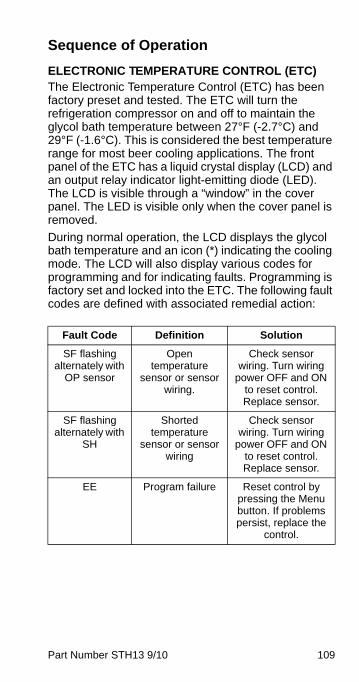
Part Number STH13 9/10 109
Sequence of Operation
ELECTRONIC TEMPERATURE CONTROL (ETC)The Electronic Temperature Control (ETC) has been factory preset and tested. The ETC will turn the refrigeration compressor on and off to maintain the glycol bath temperature between 27°F (-2.7°C) and 29°F (-1.6°C). This is considered the best temperature range for most beer cooling applications. The front panel of the ETC has a liquid crystal display (LCD) and an output relay indicator light-emitting diode (LED). The LCD is visible through a “window” in the cover panel. The LED is visible only when the cover panel is removed.
During normal operation, the LCD displays the glycol bath temperature and an icon (*) indicating the cooling mode. The LCD will also display various codes for programming and for indicating faults. Programming is factory set and locked into the ETC. The following fault codes are defined with associated remedial action:
Fault Code Definition Solution
SF flashing alternately with
OP sensor
Open temperature
sensor or sensor wiring.
Check sensor wiring. Turn wiring
power OFF and ON to reset control. Replace sensor.
SF flashing alternately with
SH
Shorted temperature
sensor or sensor wiring
Check sensor wiring. Turn wiring
power OFF and ON to reset control. Replace sensor.
EE Program failure Reset control by pressing the Menu button. If problems persist, replace the
control.
STH13_Tech.book Page 109 Wednesday, September 15, 2010 3:20 PM
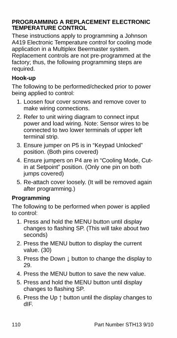
110 Part Number STH13 9/10
PROGRAMMING A REPLACEMENT ELECTRONIC TEMPERATURE CONTROLThese instructions apply to programming a Johnson A419 Electronic Temperature control for cooling mode application in a Multiplex Beermaster system. Replacement controls are not pre-programmed at the factory; thus, the following programming steps are required.
Hook-up
The following to be performed/checked prior to power being applied to control:
1. Loosen four cover screws and remove cover to make wiring connections.
2. Refer to unit wiring diagram to connect input power and load wiring. Note: Sensor wires to be connected to two lower terminals of upper left terminal strip.
3. Ensure jumper on P5 is in “Keypad Unlocked” position. (Both pins covered)
4. Ensure jumpers on P4 are in “Cooling Mode, Cut-in at Setpoint” position. (Only one pin on both jumps covered)
5. Re-attach cover loosely. (It will be removed again after programming.)
Programming
The following to be performed when power is applied to control:
1. Press and hold the MENU button until display changes to flashing SP. (This will take about two seconds)
2. Press the MENU button to display the current value. (30)
3. Press the Down ↓ button to change the display to 29.
4. Press the MENU button to save the new value.
5. Press and hold the MENU button until display changes to flashing SP.
6. Press the Up ↑ button until the display changes to dIF.
STH13_Tech.book Page 110 Wednesday, September 15, 2010 3:20 PM
Part Number STH13 9/10 111
7. Press the MENU button to display the current value. (5)
8. Press the Down ↓ button to change the display to 2.
9. Press the MENU button to save the new value.
10. Press and hold the MENU button until display changes to flashing SP.
11. Press the Down ↓ button until the display changes to SF.
12. Press the MENU button to display the current value. (1)
13. Press the Down ↓ button to change the display to 0.
14. Press the MENU button to save the new value.
15. Remove cover and place jumper on P5 in “Keypad Locked” position. (One pin exposed)
16. Replace and secure cover. Control is programmed, locked, and ready to operate.
ELECTRONIC REFRIGERATION CONTROL (ERC)NOTE: These units have part numbers that end with “E” and only applies to these units.
Prerequisites
• The glycol bath must cover the evaporator and low level probe.
Initial Power-up Delay
The control has a 30-second delay when power is connected, or disconnected and reconnected. The display will show Pd (power delay) and the seconds left in the countdown cycle.
Normal Circuit Operation
Pressing the COMP/AGIT button will start the water/glycol bath agitator immediately and initiate a 180 second compressor delay. The display will show Cd99 (compressor delay & 99 seconds) and will start to count down from 99 seconds after the first 81 seconds have elapsed. After 180 seconds the compressor and condenser fan motor energize and the COMP/AGIT LED will start flashing. Pressing any of the CIRC A, CIRC B, CARB B, or CARB A buttons will immediately
STH13_Tech.book Page 111 Wednesday, September 15, 2010 3:20 PM
112 Part Number STH13 9/10
energize the circulating pumps and turn on their respective LEDs constantly. The display will show the water/glycol bath temperature.
The compressor and condenser fan will continue to run until set temperature is reached. Once reached the compressor and condenser fan will turn off and the LED will change from flashing to constantly on to display that there is power. A 2°F rise above the set temperature will cause the compressor and condenser fan on again. This cycle will repeat as required depending on load.
Power Interruption
During a power interruption the control will resume from the point of interruption when power is reapplied and the time delay expires. Any switches/components that were energized when power was interrupted will be energized when power is reapplied.
Error Codes
E3 = Water/Glycol mix too low, add mix
E4 = Water/Glycol temp too high (>45°F)
E6 = High refrigeration temperature
NOTE: Error codes will display until corrected.
Control Programming
SER
PGM
CIRC B
CIRC A
COMP/AGIT
CARB A
CARB B
CIRC A
CIRC B
STH13_Tech.book Page 112 Wednesday, September 15, 2010 3:20 PM
Part Number STH13 9/10 113
There are 4 programming modes:
1. View conductivity
2. Add additional (third or fourth) circulation pumps
3. Set water/glycol temperature
4. Temporarily cancel display of error codes
SER Switch
• LED is energized when LON communication network is connected.
• LED is de-energized when LON communication network is disconnected.
PGM Switch
• Used to enter and exit programming modes. To enter, press and hold switch for 3 seconds.
PROGRAM MODE 1
• 0001 will display indicating Mode 1
• Wait 3 seconds C000 will display
• Press and hold CIRC A switch — Display will indicate water/glycol bath probe conductivity:
- CL0 — Water/Glycol mix too low
- CL1 — Water/Glycol mix high enough
Press and hold PGM switch for 3 seconds to exit program mode.
PROGRAM MODE 2
Add circulation pumps C & D.
• Press PGM button for 3 seconds — Display shows 0001.
• Press PGM button — Display shows 0002 program mode 2.
• Wait 3 seconds — Display shows -002 = Factory default setting.
- Pressing CIRC A button energizes/de-energizes pump A
- Pressing CIRC B button energizes/de-energizes pump B
STH13_Tech.book Page 113 Wednesday, September 15, 2010 3:20 PM
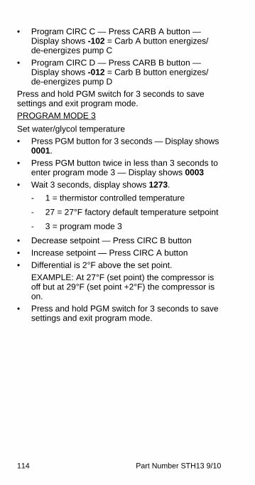
114 Part Number STH13 9/10
• Program CIRC C — Press CARB A button — Display shows -102 = Carb A button energizes/de-energizes pump C
• Program CIRC D — Press CARB B button — Display shows -012 = Carb B button energizes/de-energizes pump D
Press and hold PGM switch for 3 seconds to save settings and exit program mode.
PROGRAM MODE 3
Set water/glycol temperature
• Press PGM button for 3 seconds — Display shows 0001.
• Press PGM button twice in less than 3 seconds to enter program mode 3 — Display shows 0003
• Wait 3 seconds, display shows 1273.
- 1 = thermistor controlled temperature
- 27 = 27°F factory default temperature setpoint
- 3 = program mode 3
• Decrease setpoint — Press CIRC B button
• Increase setpoint — Press CIRC A button
• Differential is 2°F above the set point.
EXAMPLE: At 27°F (set point) the compressor is off but at 29°F (set point +2°F) the compressor is on.
• Press and hold PGM switch for 3 seconds to save settings and exit program mode.
STH13_Tech.book Page 114 Wednesday, September 15, 2010 3:20 PM
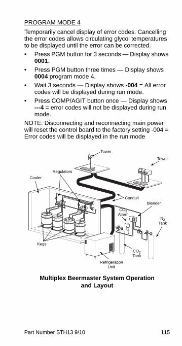
Part Number STH13 9/10 115
PROGRAM MODE 4
Temporarily cancel display of error codes. Cancelling the error codes allows circulating glycol temperatures to be displayed until the error can be corrected.
• Press PGM button for 3 seconds — Display shows 0001.
• Press PGM button three times — Display shows 0004 program mode 4.
• Wait 3 seconds — Display shows -004 = All error codes will be displayed during run mode.
• Press COMP/AGIT button once — Display shows ---4 = error codes will not be displayed during run mode.
NOTE: Disconnecting and reconnecting main power will reset the control board to the factory setting -004 = Error codes will be displayed in the run mode
Multiplex Beermaster System Operation and Layout
N2 Tank
CO2 Tank
CO2 Alarm
Refrigeration Unit
Kegs
Cooler
Regulators
Tower
Conduit
Tower
Blender
STH13_Tech.book Page 115 Wednesday, September 15, 2010 3:20 PM
116 Part Number STH13 9/10
Equipment Setup and Close Procedure
EQUIPMENT SETUP PROCEDURE1. Observe pressure of CO2 high pressure tank of
500 PSI (34 bar) or more, or bulk CO2 tank of 150 PSI or more. Primary regulator set at 90 PSI (6 bar) and the secondary regulator set at 35-40 PSI (2.4-2.6 bar) depending on the type of beer.
2. Observe the control panel to verify that all pressure gauges are set at correct operating pressures.
3. Check the kegs to make sure a sufficient number of kegs are connected in series to satisfy business volume.
4. Clean beer inlet and outlet quick disconnects at the same time tanks are replaced. Rinse disconnects in clean potable water.
EQUIPMENT CLOSE PROCEDURE1. Clean the underside of the dispensing tower
around the nozzle area with a clean damp towel.
2. Pour at least 60 oz (1.8 liters) of warm water down the drain openings.
STH13_Tech.book Page 116 Wednesday, September 15, 2010 3:20 PM
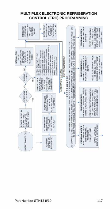
Part Number STH13 9/10 117
MULTIPLEX ELECTRONIC REFRIGERATION CONTROL (ERC) PROGRAMMING
PO
WE
R U
P D
ELA
YS
HO
WS
“Pd3
0”A
ND
CO
UN
TSD
OW
N T
O “P
d00"
SU
PP
LY P
OW
ER
ON
NO
RM
AL
RU
NM
OD
ED
ISP
LAY
SH
OW
SC
IRC
WAT
ER
TEM
P(S
) OR
WAT
ER
BAT
HTE
MP
IN B
EE
RM
OD
E
CO
MP
/AG
ITS
WIT
CH
ON
NO
YE
S
P R
O G
R A
M M
O D
ETO
EN
TER
, PR
ES
S A
ND
HO
LD P
GM
SW
ITC
H F
OR
MIN
IMU
M O
F 3
SE
CO
ND
S, D
ISP
LAY
SH
OW
S “0
001”
TO C
HA
NG
E T
O N
EX
T P
RO
GR
AM
MO
DE
, PR
ES
S P
GM
BU
TTO
N S
EQ
UE
NTI
ALL
Y IN
LE
SS
TH
AN
3 S
EC
ON
DS
FR
OM
EN
TER
(“00
02”,
ETC
)TO
EX
IT, P
RE
SS
AN
D H
OLD
PG
M S
WIT
CH
FO
R M
INIM
UM
OF
3 S
EC
ON
DS
, DIS
PLA
Y S
HO
WS
NO
RM
AL
RU
N M
OD
ERE
SP
EC
TIV
ELE
D C
OM
ES
ON
CO
NS
TAN
T,FL
AS
HE
S IF
LOA
D C
ON
TRO
LC
IRC
UIT
ON
PR
ES
S A
NY
SW
ITC
H T
OTU
RN
ON
LO
AD
OR
LO
AD
CO
NTR
OL
CIR
CU
IT
AG
ITAT
OR
CO
ME
S O
NC
ON
STA
NTL
Y
CO
MP
RE
SS
OR
CO
ME
S O
N A
FTE
RD
ELA
Y, IF
CO
NTR
OL
CIR
CU
ITR
EQ
UIR
ES
EN
TER
PR
OG
RA
M M
OD
E
EX
IT P
RO
GR
AM
MO
DE
PRO
GR
AM
MO
DE
4TE
MP
OR
AR
ILY
DIS
AB
LEE
RR
OR
S
PR
ES
S P
GM
SW
ITC
HTH
RE
E T
IME
S (3
) IN
LES
S T
HA
N 3
SE
CO
ND
SD
ISP
LAY
“000
4”, W
AIT
THR
EE
(3) S
EC
ON
DS
DIS
PLA
Y “-
004”
PRO
GR
AM
MO
DE
3P
RO
GR
AM
TE
MP
ER
ATU
RE
CO
NTR
OL
OF
WAT
ER
BAT
H(B
EE
R)
PR
ES
S P
GM
SW
ITC
H T
WIC
E(2
) IN
LE
SS
TH
AN
3S
EC
ON
DS
, DIS
PLA
Y “0
003”
,W
AIT
TH
RE
E (3
) SE
CO
ND
SD
ISP
LAY
“-00
3”
PRO
GR
AM
MO
DE
2P
RO
GR
AM
ON
E (1
) OR
TW
O (2
)M
OR
E C
IRC
ULA
TIN
G P
UM
PS
PR
ES
S P
GM
SW
ITC
H O
NC
E (1
)IN
LE
SS
TH
AN
3 S
EC
ON
DS
DIS
PLA
Y “0
002”
, WA
IT T
HR
EE
(3) S
EC
ON
DS
DIS
PLA
Y “-
002”
PRO
GR
AM
MO
DE
1R
EA
D C
ON
DU
CTI
VIT
Y,TE
MP
ER
ATU
RE
,P
RE
SS
UR
EC
HA
NG
E U
NIT
S
WA
IT 3
SE
CO
ND
SD
ISP
LAY
SH
OW
S “C
000”
CO
MP
RE
SS
OR
DE
LAY
SH
OW
S“C
d99”
AN
DC
OU
NTS
DO
WN
TO “C
d00”
ER
RO
RC
OD
E(S
)N
O
YE
S
ER
RO
R C
OD
ED
ISP
LAY
S T
ILL
CO
RR
EC
TED
MU
LTIP
LEE
RR
OR
S C
YC
LEP
GM
MO
DE
4O
VE
RR
IDE
S
E1
= Lo
w W
ater
Sup
ly P
ress
ure
E2
= Lo
w C
o2 P
ress
ure
E3
= Lo
w W
ater
Lev
el -
Wat
er B
ath
E4
= H
igh
Wat
er B
ath
Tem
pera
ture
E5
= H
igh
Wat
er S
uppl
y P
ress
ure
E6
= H
igh
Ref
riger
atio
n Te
mpe
ratu
reE
7 =
Hig
h Ic
e B
ank
Siz
e (P
robe
Sen
sor 2
)E
8 =
Long
Car
b A
Run
Tim
eE
9 =
Long
Car
b B
Run
Tim
eS
horte
d Tr
ansd
ucer
= "-
---"
Ope
n Tr
ansd
ucer
= "=
==="
STH13_Tech.book Page 117 Wednesday, September 15, 2010 3:20 PM
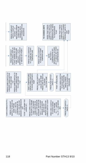
118 Part Number STH13 9/10
“C00
0”(C
ON
DU
CTI
VIT
Y)
PR
ES
S C
OM
P/A
GIT
SW
ITC
H T
O S
HO
W IC
EB
AN
K P
RO
BE
“CC
11” =
NO
ICE
CO
MP
RE
SS
OR
ON
“CC
10”=
ICE
ON
LO
WS
EN
SO
R C
OM
PR
ES
SO
RO
FF“C
C00
” = IC
E B
AN
K T
OO
LAR
GE
(E7)
PR
ES
S C
AR
B A
SW
ITC
HTO
SH
OW
LLC
PR
OB
E“C
A00
” = N
O W
ATE
RC
AR
B A
MO
TOR
ON
“CA
01”=
LO
W S
EN
SO
RIN
WAT
ER
, MO
TOR
ON
“CA
11” =
LO
W &
HIG
HS
EN
SO
R IN
WAT
ER
,M
OTO
R O
FFR
EP
EAT
AB
OV
E F
OR
CA
RB
B S
WIT
CH
“CbX
X”
PR
ES
CIR
C A
SW
ITC
HTO
SH
OW
WAT
ER
LEV
EL
PR
OB
E“C
L_1”
= W
ATE
R“C
L_0”
= L
OW
WAT
ER
(E3)
PR
ES
S C
OM
P/A
GIT
SW
ITC
H, D
ISP
LAY
SH
OW
S “-
--4”
IND
ICAT
ING
ER
RO
RC
OD
ES
WIL
L B
ED
ISA
BLE
D U
NTI
LN
EX
T P
OW
ER
OFF
/ON
SE
QU
EN
CE
“F00
0” (T
EM
PE
RAT
UR
E)
PR
ES
S C
AR
B A
SW
ITC
HTO
SH
OW
WAT
ER
BAT
HTE
MP
PR
ES
S C
IRC
A S
WIT
CH
TO S
HO
WLI
QU
ID L
INE
TE
MP
PR
ES
S C
IRC
B S
WIT
CH
TO S
HO
WS
UC
TIO
N T
EM
P
“P00
0” (P
RE
SS
UR
E)
PR
ES
S C
AR
B A
SW
ITC
HTO
SH
OW
WAT
ER
SU
PP
LY P
RE
SS
UR
EP
RE
SS
CA
RB
BS
WIT
CH
TO
SH
OW
CO
2P
RE
SS
UR
E
PR
ES
S C
OM
P/A
GIT
SW
ITC
H O
NC
E, D
ISP
LAY
=”1X
X3"
WH
ER
E X
X=
SE
TP
OIN
T TE
MP
ER
ATU
RE
(DE
FAU
LT =
“127
3”)
(DIF
FER
EN
TIA
L FI
XE
D A
T2°
AB
OV
E S
ET
PO
INT)
PR
ES
S C
IRC
A S
WIT
CH
TO L
OW
ER
SE
T P
OIN
TTE
MP
ER
ATU
RE
PR
ES
S C
IRC
B S
WIT
CH
TO R
AIS
E S
ET
PO
INT
TEM
PE
RAT
UR
E
NO
TE:
SE
T P
OIN
T =
CO
MP
RE
SS
OR
OFF
DIF
FER
EN
TIA
L IS
FIX
ED
AT 2
°F A
BO
VE
SE
T P
OIN
TC
OM
PR
ES
SO
R O
N
PR
ES
S C
AR
B A
SW
ITC
H T
OC
ON
VE
RT
CA
RB
A M
OTO
RTO
CIR
C M
OTO
R“-
102”
PR
ES
S C
AR
B B
SW
ITC
H T
OC
ON
VE
RT
CA
RB
B M
OTO
RTO
CIR
C M
OTO
R“-
112”
PR
ES
S P
GM
SW
ITC
HO
NC
E (1
)
PR
ES
S P
GM
SW
ITC
HO
NC
E (1
)
TO C
HA
NG
E U
NIT
S
WH
EN
“F00
0” P
RE
SS
CO
MP
/AG
IT S
WIT
CH
ON
CE
(1) T
O C
HA
NG
ETE
MP
ER
ATU
RE
UN
ITS
TO C
EN
TIG
RA
DE
“FC
00”
WH
EN
“P00
0” P
RE
SS
CO
MP
/AG
IT S
WIT
CH
ON
CE
(1) T
O C
HA
NG
EP
RE
SS
UR
E U
NIT
S T
OB
AR
“Fb0
0”
STH13_Tech.book Page 118 Wednesday, September 15, 2010 3:20 PM
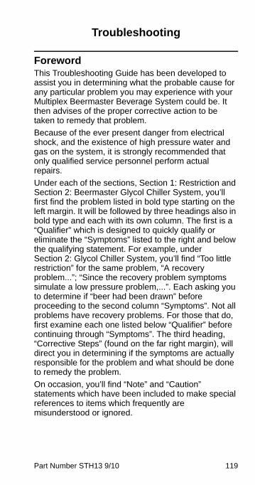
Part Number STH13 9/10 119
Troubleshooting
ForewordThis Troubleshooting Guide has been developed to assist you in determining what the probable cause for any particular problem you may experience with your Multiplex Beermaster Beverage System could be. It then advises of the proper corrective action to be taken to remedy that problem.
Because of the ever present danger from electrical shock, and the existence of high pressure water and gas on the system, it is strongly recommended that only qualified service personnel perform actual repairs.
Under each of the sections, Section 1: Restriction and Section 2: Beermaster Glycol Chiller System, you’ll first find the problem listed in bold type starting on the left margin. It will be followed by three headings also in bold type and each with its own column. The first is a “Qualifier” which is designed to quickly qualify or eliminate the “Symptoms” listed to the right and below the qualifying statement. For example, under Section 2: Glycol Chiller System, you’ll find “Too little restriction” for the same problem, “A recovery problem...”; “Since the recovery problem symptoms simulate a low pressure problem,...”. Each asking you to determine if “beer had been drawn” before proceeding to the second column “Symptoms”. Not all problems have recovery problems. For those that do, first examine each one listed below “Qualifier” before continuing through “Symptoms”. The third heading, “Corrective Steps” (found on the far right margin), will direct you in determining if the symptoms are actually responsible for the problem and what should be done to remedy the problem.
On occasion, you’ll find “Note” and “Caution” statements which have been included to make special references to items which frequently are misunderstood or ignored.
STH13_Tech.book Page 119 Wednesday, September 15, 2010 3:20 PM
120 Part Number STH13 9/10
This guide is intended to assist you in locating the cause of a problem. It is not, however, to be considered a service and repair manual in that Multiplex models vary in design.
It has been written to encompass all model Beermaster Glycol Chillers. Some differences from model to model will become obvious and it will be required of the reader to apply this guide to each unit.
STH13_Tech.book Page 120 Wednesday, September 15, 2010 3:20 PM
Part Number STH13 9/10 121
ChecklistIf a problem arises during operation of your refrigeration unit, follow the checklist below. Routine adjustments and maintenance procedures are not covered by the warranty.
! WarningOnly trained and certified electrical and plumbingtechnicians must service this unit. All wiring andplumbing must conform to national and localcodes.
! WarningThe unit should be unplugged when servicing,except when electrical tests are required. Use extreme care during electrical circuit tests.Live circuits may be exposed.
STH13_Tech.book Page 121 Wednesday, September 15, 2010 3:20 PM
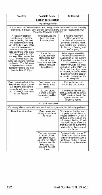
122 Part Number STH13 9/10
Problem Possible Cause To Correct
Section 1: Restriction
Too little restriction
Too much or too little restriction in a draught beer system will cause drawing problems. If draught beer system does not have enough restriction it may
cause the following problems:
A recovery problem simply means that the
beer is leaving the beer line faster than the keg
can fill the line. When this occurs it creates a
vacuum in the keg which acts as if there was a low pressure on the beer in
the keg. This causes the CO2 to come out of the
beer line causing foaming problems. (The following
symptoms occur most frequently during the high
volume time of day.)
When drawing one beer, the beer flows very fast.
Since the recovery problem symptoms
simulate a low pressure problem, check to make
sure that the CO2 pressure in the keg is flowing and
set properly.
If a pitcher is drawn, the beer starts clear then starts to show
intermittent streaks of foam followed
by all foam.
Refer to your records to recheck your restriction
calculation for the system. If you find your line does
not have enough restriction, add the extra
restriction to the 3/16" end of the beer line. If you have no records, make up a new
beer line with the proper restriction and replace the
existing line.
Beer draws too fast. If the beer draws clear but too fast and the pressure is properly set, there may
not be enough restriction in the system.
Beer draws clear but foams in the
glass.
Follow the second corrective step above.
The beer draws too fast to satisfy
the retailer and his help.
If the beer still flows too fast, continue to add more 3/16" restrictor line to the
system to meet the retailer’s needs.
Too much restriction
If a draught beer system is over restricted it may cause the following problems:
Beer draws too slow Beer draws too slowly with little or
no head.
First, ensure that the keg is properly tapped. Second, ensure that the CO2 is set at the proper pressure and is flowing to the keg. Check the beer faucet to ensure
that there is no burr by the vent hole on the inside of
the faucet.
The beer appears to flutter or swirl out of the faucet
causing the CO2 to break out of the beer and thus
creating excess foam.
Systematically remove 6" of the 3/16" restrictor line until the beer flows with a full faucet and at a rate of
flow desired by the retailer.
STH13_Tech.book Page 122 Wednesday, September 15, 2010 3:20 PM
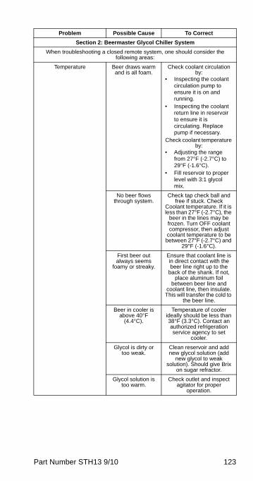
Part Number STH13 9/10 123
Section 2: Beermaster Glycol Chiller System
When troubleshooting a closed remote system, one should consider the following areas:
Temperature Beer draws warm and is all foam.
Check coolant circulation by:
• Inspecting the coolant circulation pump to ensure it is on and running.
• Inspecting the coolant return line in reservoir to ensure it is circulating. Replace pump if necessary.
Check coolant temperature by:
• Adjusting the range from 27°F (-2.7°C) to 29°F (-1.6°C).
• Fill reservoir to proper level with 3:1 glycol mix.
No beer flows through system.
Check tap check ball and free if stuck. Check
Coolant temperature. If it is less than 27°F (-2.7°C), the
beer in the lines may be frozen. Turn OFF coolant compressor, then adjust
coolant temperature to be between 27°F (-2.7°C) and
29°F (-1.6°C).
First beer out always seems
foamy or streaky.
Ensure that coolant line is in direct contact with the beer line right up to the
back of the shank. If not, place aluminum foil
between beer line and coolant line, then insulate. This will transfer the cold to
the beer line.
Beer in cooler is above 40°F
(4.4°C).
Temperature of cooler ideally should be less than 38°F (3.3°C). Contact an authorized refrigeration service agency to set
cooler.
Glycol is dirty or too weak.
Clean reservoir and add new glycol solution (add
new glycol to weak solution). Should give Brix
on sugar refractor.
Glycol solution is too warm.
Check outlet and inspect agitator for proper
operation.
Problem Possible Cause To Correct
STH13_Tech.book Page 123 Wednesday, September 15, 2010 3:20 PM
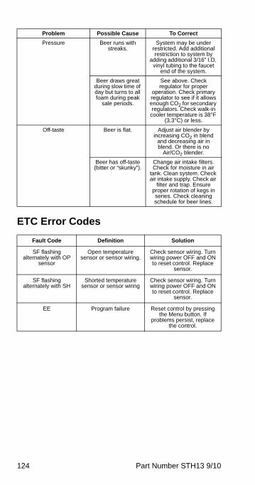
124 Part Number STH13 9/10
ETC Error Codes
Pressure Beer runs with streaks.
System may be under restricted. Add additional restriction to system by
adding additional 3/16" I.D. vinyl tubing to the faucet
end of the system.
Beer draws great during slow time of day but turns to all foam during peak
sale periods.
See above. Check regulator for proper
operation. Check primary regulator to see if it allows enough CO2 for secondary regulators. Check walk-in
cooler temperature is 38°F (3.3°C) or less.
Off-taste Beer is flat. Adjust air blender by increasing CO2 in blend
and decreasing air in blend. Or there is no
Air/CO2 blender.
Beer has off-taste (bitter or “skunky”).
Change air intake filters. Check for moisture in air
tank. Clean system. Check air intake supply. Check air
filter and trap. Ensure proper rotation of kegs in series. Check cleaning schedule for beer lines.
Fault Code Definition Solution
SF flashing alternately with OP
sensor
Open temperature sensor or sensor wiring.
Check sensor wiring. Turn wiring power OFF and ON to reset control. Replace
sensor.
SF flashing alternately with SH
Shorted temperature sensor or sensor wiring
Check sensor wiring. Turn wiring power OFF and ON to reset control. Replace
sensor.
EE Program failure Reset control by pressing the Menu button. If
problems persist, replace the control.
Problem Possible Cause To Correct
STH13_Tech.book Page 124 Wednesday, September 15, 2010 3:20 PM
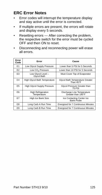
Part Number STH13 9/10 125
ERC Error Notes• Error codes will interrupt the temperature display
and stay active until the error is corrected.
• If multiple errors are present, the errors will rotate and display every 5 seconds.
• Resetting errors — After correcting the problem, the respective switch for the error must be cycled OFF and then ON to reset.
• Disconnecting and reconnecting power will erase all errors.
Error Code Error Cause
E1 Low Glycol Supply Pressure Lower than 5 PSI for 5 Seconds
E2 Low CO2 Pressure Lower than 10 PSI for 5 Seconds
E3 Low Glycol Level – Glycol Bath
Must Cover Top of Evaporator
E4 High Glycol Bath Temperature Glycol Bath Temperature Greater Than 45°F
E5 High Glycol Supply Pressure Glycol Pressure Greater than 75 PSI
E6 High Refrigeration Temperature
Discharge Line Temperature Greater than 190°F
E7 High Ice Bank Size Ice Contacting Center Ice Bank Probe
E8 Long Carb A Run Time Energized for 7 Continuous Minutes
E9 Long Carb B Run Time Energized for 7 Continuous Minutes
STH13_Tech.book Page 125 Wednesday, September 15, 2010 3:20 PM
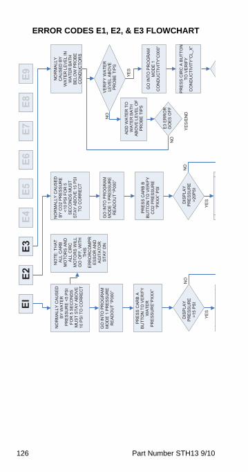
126 Part Number STH13 9/10
ERROR CODES E1, E2, & E3 FLOWCHARTEI
YES
NO
NO
RM
ALLY
CAU
SED
BY
WA
TER
P
RE
SS
UR
E <
5 P
SI
FOR
5 S
ECO
ND
SM
US
T S
TAY
AB
OV
E
10 P
SI T
O C
OR
REC
T
E3E4
E5E6
E7E8
E9E2
NO
YES
NO
NO
YES
YES
/EN
D
NO
TE: T
HAT
A
LL C
AR
B
MO
TOR
S AN
D
ALL
CIR
C
MO
TOR
S W
ILL
GO
OFF
, WIT
H
THIS
ER
RO
RC
OM
PRES
SOR
AN
D
AG
ITA
TOR
STA
Y O
N
NO
RM
ALLY
CAU
SED
B
Y C
O2
PR
ES
SU
RE
<1
0 P
SI F
OR
5
SE
CO
ND
S M
US
T S
TAY
AB
OV
E 1
5 PS
I TO
CO
RR
ECT
NO
RM
ALLY
CA
US
ED
BY
WA
TER
LE
VE
L IN
W
ATE
R B
ATH
B
ELO
W P
RO
BE
C
ON
DU
CTO
RS
GO
INTO
PR
OG
RA
M
MO
DE
1 P
RES
SU
RE
R
EA
DO
UT
“P00
0”
GO
INTO
PR
OG
RA
M
MO
DE
1 P
RES
SU
RE
R
EA
DO
UT
“P00
0”
PR
ES
S C
AR
B A
BU
TTO
N T
O V
ERIF
Y W
ATE
R
PR
ES
SU
RE
“PX
XX
”
DIS
PLA
Y P
RE
SS
UR
E>1
5 P
SI
PR
ES
S C
AR
B B
BU
TTO
N T
O V
ERIF
Y C
O2
PR
ES
SU
RE
“P
XX
X” P
SI
DIS
PLA
Y P
RE
SS
UR
E>2
0PS
I
VE
RIF
Y W
ATE
R
LEV
EL
AB
OV
E P
RO
BE
TIP
S
ADD
WA
TER
TO
W
ATE
R B
ATH
A
BO
VE
LEV
EL
OF
PR
OB
E T
IPS
GO
INTO
PR
OG
RA
M
MO
DE
1
CO
ND
UC
TIV
ITY“
C00
0”E3
ER
RO
R
GO
ES
OFF
PR
ES
S C
IRC
A B
UTT
ON
TO
VE
RIF
Y C
ON
DU
CTI
VIT
Y“C
L_X”
STH13_Tech.book Page 126 Wednesday, September 15, 2010 3:20 PM
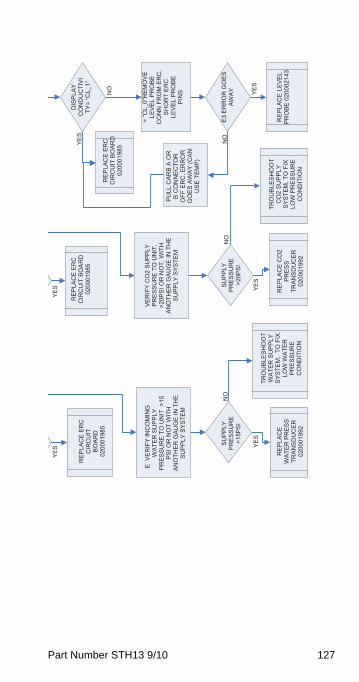
Part Number STH13 9/10 127
VE
RIF
Y IN
CO
MIN
G
WA
TER
SU
PPLY
P
RE
SS
UR
E T
O U
NIT
>15
PS
I OR
NO
T W
ITH
AN
OTH
ER G
AUG
E IN
TH
E S
UP
PLY
SYS
TEM
E
RE
PLA
CE
ER
C
CIR
CU
IT
BOAR
D02
0001
985
YES
NO
YES
NO
YES
YES
NO
YES
NO
YES
RE
PLA
CE
ER
C
CIR
CU
IT B
OAR
D
0200
0198
5
RE
PLA
CE
ER
C
CIR
CU
IT B
OAR
D
0200
0198
5
SU
PP
LY
PR
ES
SU
RE
>15P
SI
SU
PP
LY
PR
ES
SU
RE
>20P
SI
RE
PLA
CE
WA
TER
PR
ES
S
TRAN
SDU
CER
0200
0199
2
TRO
UB
LES
HO
OT
WA
TER
SU
PPLY
S
YSTE
M,
TO F
IX
LOW
WA
TER
P
RE
SS
UR
EC
ON
DIT
ION
RE
PLA
CE
CO
2 P
RE
SS
TRAN
SDU
CER
0200
0199
2
TRO
UB
LES
HO
OT
CO
2 S
UP
PLY
S
YSTE
M, T
O F
IX
LOW
PR
ES
SU
RE
CO
ND
ITIO
N
DIS
PLA
Y C
ON
DU
CTI
VITY
= “C
L_1”
= “C
L_0"
RE
MO
VE
LE
VE
L P
RO
BE
CO
NN
FR
OM
ER
C,
SHO
RT
ERC
LE
VE
L P
RO
BE
PIN
S
VE
RIF
Y C
O2
SU
PPLY
P
RE
SS
UR
E T
O U
NIT
, >2
0PS
I OR
NO
T, W
ITH
AN
OTH
ER G
AUG
E IN
TH
E S
UP
PLY
SYS
TEM
PU
LL C
ARB
A O
R
B C
ON
NEC
TOR
O
FF E
RC
, ER
RO
R
GO
ES
AW
AY
(CAN
U
SE
TE
MP
)
E3 E
RR
OR
GO
ES
AWA
Y
RE
PLA
CE
LE
VEL
PR
OB
E 0
2000
2143
STH13_Tech.book Page 127 Wednesday, September 15, 2010 3:20 PM
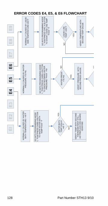
128 Part Number STH13 9/10
ERROR CODES E4, E5, & E6 FLOWCHARTEI
E2E3
E4E5
E6E7
E8E9
NO
RM
ALLY
CAU
SED
BY
WA
TER
B
ATH
TE
MP
ER
ATU
RE
> 4
5°F
NO
RM
ALLY
CAU
SED
BY
WA
TER
P
RE
SS
UR
E >
75 P
SI,
NO
RM
ALLY
CAU
SED
BY
LIQ
UID
S
IDE
TE
MP
ER
ATU
RE
>200
°F
NO
YES
GO
INTO
PR
OG
RA
MM
ING
MO
DE
1, “F
000”
PR
ES
S C
AR
B A
BU
TTO
N
TO S
HO
W W
ATE
R B
ATH
TE
MP
“FX
XX
” °F
GO
INTO
PR
OG
RA
MM
ING
MO
DE
1, “P
000”
PR
ESS
CA
RB
A B
UTT
ON
TO
SH
OW
INC
OM
ING
WA
TER
P
RE
SS
UR
E “P
XX
X”
PS
I
GO
INTO
PR
OG
RA
MM
ING
MO
DE
1, “F
000”
PR
ES
S C
IRC
A B
UTT
ON
TO
SH
OW
LIQ
UID
LIN
E T
EM
P “F
XX
X” °
F
WA
TER
BAT
H
TEM
P D
ISLA
Y N
O
YES
WA
TER
PR
ES
S
>75
PSI
N
O>4
5 °F
NO
YES
LIQ
UID
LIN
E TE
MP
>20
0°F
VE
RIF
Y TE
MP
WIT
H S
EC
ON
D
THER
MO
MET
ERIF
STI
LL
<45°
FRE
PLA
CE
ER
C B
OA
RD
V
ER
IFY
PR
ES
SU
RE
WIT
H
SE
CO
ND
PR
ES
S G
AU
GE
VE
RIF
Y TE
MPE
RAT
UR
E W
ITH
SE
CO
ND
TEM
P G
AUG
E 02
0001
985
STH13_Tech.book Page 128 Wednesday, September 15, 2010 3:20 PM
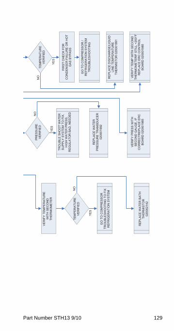
Part Number STH13 9/10 129
NO
YES
YES
NO
YES
NO
PR
ES
SU
RE
VE
RIF
IED
TE
MPE
RAT
UR
EV
ER
IFIE
D
VE
RIF
Y TE
MP
ER
ATU
RE
W
ITH
SEC
ON
D
THER
MO
MET
ER
TRO
UBL
E SH
OO
T W
ATE
R
SU
PP
LY S
YSTE
M T
O F
IX.
HIG
H W
ATE
R P
RES
S,
RE
GU
LATO
R B
AD
, NE
ED
ED
FIR
ST C
HEC
K FO
R
CO
ND
ENSE
R F
AILU
RE
OR
HO
T G
AS
BYP
AS
S
TEM
PER
ATU
RE
VE
RIF
IED
G
O T
O C
OM
PR
ESS
OR
/ R
EFR
IGE
RA
TIO
N S
YSTE
M
TRO
UB
LES
HO
OTI
NG
RE
PLA
CE
WA
TER
PR
ESSU
RE
TRAN
SDU
CER
02
0001
992
GO
TO
CO
MP
RE
SSO
R
TRO
UB
LES
HO
OTI
NG
TO
FIX
R
EFR
IGE
RA
TIO
N S
YSTE
M
RE
PLA
CE
DIS
CH
ARG
E/L
IQU
ID
LIN
E T
EM
PE
RA
TUR
E
THE
RM
ISTO
R 0
2000
1991
VE
RIF
Y TE
MP
WIT
H S
EC
ON
D
THE
RM
OM
ETE
RIF
STI
LL <
200°
F R
EPLA
CE
ERC
CO
NTR
OL
BO
AR
D 0
2000
1985
VE
RIF
Y P
RE
SS
WIT
H
SEC
ON
D G
AUG
E, IF
C
OR
REC
TREP
LAC
E ER
C
BO
AR
D 0
2000
1985
R
EP
LAC
E W
ATE
R B
ATH
TH
ERM
ISTO
R
0200
0214
2
STH13_Tech.book Page 129 Wednesday, September 15, 2010 3:20 PM
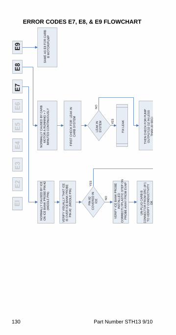
130 Part Number STH13 9/10
ERROR CODES E7, E8, & E9 FLOWCHARTEI
E2E3
E4E5
E6E7
E8E9
NO
RM
ALLY
CAU
SED
BY
CAR
B M
OTO
R A
RU
NN
ING
> 7
M
INU
TES
CO
NTI
NU
OU
SLY
NO
RM
ALLY
CAU
SED
BY
ICE
ON
ICE
BA
NK
PR
OB
E P
IN #
2 (M
IDD
LE P
IN)
SA
ME
AS
E8
FOR
CA
RB
B
MO
TOR
/PU
MP
NO
YES
VE
RIF
Y V
ISU
ALL
Y TH
AT
ICE
IS O
VE
R IC
E B
AN
K P
RO
BE
PIN
#2
(MID
DLE
PIN
) FI
RST
CH
ECK
FOR
LEA
K IN
C
AR
B S
YSTE
M
YES
NO
PIN
#2
CO
VE
RE
D IN
IC
E
LEA
K IN
S
YSTE
M
VE
RIF
Y IC
E B
AN
K P
RO
BE
INS
TALL
ED
CO
RR
EC
TLYP
LAS
TIC
STE
P O
N
PR
OB
E A
WA
Y FR
OM
EV
AP
FI
X L
EAK
UN
-PLU
G C
ARB
B C
ON
NEC
TOR
FR
OM
ER
C (#
1)
TO V
ERIF
Y C
ON
DU
CTI
VIT
Y O
K
THEN
CH
ECK
FOR
PU
MP
OU
TPU
T(32
OZ
IN L
ES
S TH
AN
20S
EC
)
STH13_Tech.book Page 130 Wednesday, September 15, 2010 3:20 PM
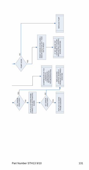
Part Number STH13 9/10 131
NO
NO
YES
YES
YES
NO
“E7”
ER
RO
R
GO
ES
AW
AY
PU
MP
GO
OD
UN
-PLU
G IC
E BA
NK
PRO
BE
CO
NN
ECTO
R (#
3) F
RO
M E
RC
BO
ARD
RE
SE
T E
RR
OR
(PU
SH
CA
RB
A
AND
/OR
B B
UTT
ON
OFF
, TH
EN
ON
TO
RE
SE
T C
OM
PR
ES
SO
R O
N T
OO
LO
NG
GO
TOC
OM
PR
ES
SO
R /
RE
FRIG
ER
ATI
ON
TRO
UB
LES
HO
OTI
NG
“E7”
ER
RO
R
GO
ES
AW
AY
IF “E
8” A
ND
/OR
“E9”
C
ON
TIN
UE
TO O
CC
UR
R
EPLA
CE
ERC
CO
NTR
OL
BO
AR
D 0
2000
1985
RE
PLA
CE
ER
C
CO
NTR
OL
BO
AR
D IF
PR
OBL
EM C
ON
TIN
UES
0200
0198
5
RE
PLA
CE
ICE
BAN
K
PR
OB
E 0
2000
2091
R
EP
LAC
E P
UM
P
STH13_Tech.book Page 131 Wednesday, September 15, 2010 3:20 PM
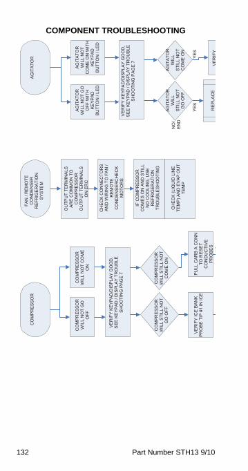
132 Part Number STH13 9/10
COMPONENT TROUBLESHOOTINGFA
N /
REM
OTE
C
ON
DEN
SER
RE
FRIG
ER
ATI
ON
SYS
TEM
AG
ITA
TOR
CO
MP
RE
SS
OR
YES
YES
NO
/EN
D
NO
OU
TPU
T TE
RM
INAL
S AR
E C
OM
MO
N T
O
CO
MP
RE
SS
OR
OU
TPU
T TE
RM
INAL
S O
N E
RC
AG
ITA
TOR
WIL
L N
OT
GO
O
FF W
ITH
K
EYP
AD
BU
TTO
N /
LED
AG
ITA
TOR
WIL
L N
OT
CO
ME
ON
WIT
H
KE
YPA
D
BUTT
ON
/ LE
D
CO
MP
RE
SS
OR
WIL
L N
OT
GO
O
FF
CO
MP
RE
SS
OR
WIL
L N
OT
CO
ME
O
N
CH
ECK
CO
NN
ECTO
RS
AND
WIR
ING
TO
FA
N /
REM
OTE
CO
ND
ENSE
RC
HE
CK
MO
TOR
S
VE
RIF
Y K
EYP
AD
/DIS
PLA
Y G
OO
D,
SE
E K
EYP
AD
/ D
ISP
LAY
TRO
UB
LE
SH
OO
TIN
G P
AG
E 7
VE
RIF
Y K
EYP
AD
/DIS
PLA
Y G
OO
D,
SE
E K
EYP
AD
/ D
ISP
LAY
TRO
UB
LE
SH
OO
TIN
G P
AG
E 7
IF C
OM
PR
ES
SO
R
CO
ME
S O
N A
ND
STI
LL
NO
CO
OLI
NG
, USE
R
EFR
IGE
RA
TIO
NTR
OU
BLES
HO
OTI
NG
CO
MP
RE
SS
OR
WIL
L S
TILL
NO
T G
O O
FF
CO
MP
RE
SS
OR
WIL
L S
TILL
NO
T C
OM
E O
N
AG
ITA
TOR
WIL
L S
TILL
NO
T C
OM
E O
N
AG
ITA
TOR
WIL
L S
TILL
NO
T G
O O
FF
CH
ECK
(LIQ
UID
LIN
E TE
MP
) AN
D E
VAP
OU
T TE
MP
VE
RIF
Y IC
E B
AN
K P
RO
BE
TIP
#1
IN IC
E
PULL
CAR
B A
CO
NN
TO
RE
SE
T C
ON
DU
CTI
VE
PR
OB
ES
RE
PLA
CE
VE
RIF
Y
STH13_Tech.book Page 132 Wednesday, September 15, 2010 3:20 PM
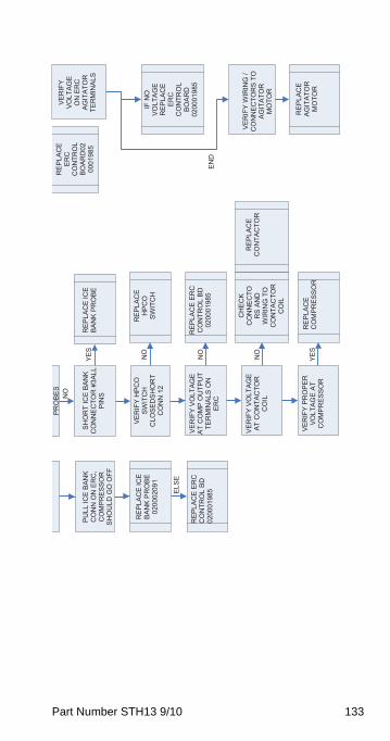
Part Number STH13 9/10 133
END
NO
NO
NO
YES
NO
YES
ELS
E
PR
OB
ES
RE
PLA
CE
ERC
CO
NTR
OL
BO
AR
D02
0001
985
VE
RIF
Y V
OLT
AG
E O
N E
RC
AG
ITA
TOR
TER
MIN
ALS
PU
LL IC
E B
AN
K C
ON
N O
N E
RC
, C
OM
PR
ES
SO
RS
HO
ULD
GO
OFF
SH
OR
T IC
E B
AN
K
CO
NN
ECTO
R #
3ALL
P
INS
RE
PLA
CE
ICE
B
AN
K P
RO
BE
RE
PLA
CE
HPC
OSW
ITC
H
VER
IFY
HPC
O
SWIT
CH
C
LOSE
DSH
OR
TC
ON
N 1
2
RE
PLA
CE
ICE
B
AN
K P
RO
BE
0200
0209
1IF
NO
V
OLT
AG
E R
EP
LAC
EER
CC
ON
TRO
LBO
ARD
0200
0198
5R
EPLA
CE
ERC
C
ON
TRO
L BD
02
0001
985
VE
RIF
Y V
OLT
AG
E A
T C
OM
P O
UTP
UT
TER
MIN
ALS
ON
ER
C
RE
PLA
CE
ER
C
CO
NTR
OL
BD
0200
0198
5
CH
ECK
CO
NN
ECTO
RS
AND
W
IRIN
G T
O
CO
NTA
CTO
RC
OIL
VER
IFY
WIR
ING
/ C
ON
NEC
TOR
S TO
A
GIT
ATO
RM
OTO
R
RE
PLA
CE
CO
NTA
CTO
RV
ER
IFY
VO
LTA
GE
AT C
ON
TAC
TOR
C
OIL
RE
PLA
CE
AG
ITA
TOR
MO
TOR
VE
RIF
Y P
RO
PE
R
VO
LTA
GE
AT
CO
MP
RE
SS
OR
RE
PLA
CE
CO
MP
RE
SS
OR
STH13_Tech.book Page 133 Wednesday, September 15, 2010 3:20 PM
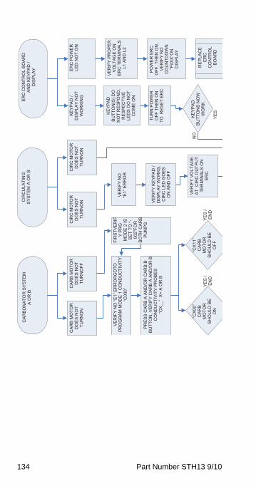
134 Part Number STH13 9/10
CIR
CU
LATI
NG
S
YSTE
M A
OR
B
ERC
CO
NTR
OL
BOAR
D
AN
D K
EYP
AD
/
DIS
PLA
Y
CA
RB
ON
ATO
R S
YSTE
M
A O
R B
YES
/ E
ND
CAR
B M
OTO
R
DO
ES
NO
T TU
RN
ON
CAR
B M
OTO
R
DO
ES
NO
T TU
RN
OFF
CIR
C M
OTO
R
DO
ES
NO
T TU
RN
ON
CIR
C M
OTO
R
DO
ES
NO
T TU
RN
ON
KE
YPA
D /
DIS
PLA
Y N
OT
WO
RKI
NG
ERC
PO
WE
R
LED
NO
T O
N
KE
YPA
D
BU
TTO
N(S
) DO
N
OT
RES
PON
D,
RE
SP
EC
TIV
E LE
DS
DO
NO
T C
OM
E O
N
VE
RIF
Y P
RO
PE
R
VO
LTA
GE
ON
ER
C T
ERM
INAL
S L1
AN
D L
2
FIR
STVE
RIF
Y P
RG
M
OD
E 2
IS
SE
T TO
“-00
2”FO
RBO
TH C
ARB
PU
MP
S
VER
IFY
NO
“E1”
ER
RO
RG
OTO
PR
OG
RAM
MO
DE
1 C
ON
DU
CTI
VIT
Y “C
000”
VE
RIF
Y N
O
“E1”
ER
RO
R
PR
ES
S C
AR
B A
AN
D/O
R C
AR
B B
B
UTT
ON
, VE
RIF
Y C
AR
B A
AN
D/O
R B
C
ON
DU
CTI
VIT
Y P
RO
BE
S
YES
NO
POW
ER
ER
C
OFF
, TH
EN O
N,
VE
RIF
Y N
O
CO
UN
TDO
WN
“P
dXX
”ON
D
ISP
LAY
TUR
N P
OW
ER
O
FF T
HEN
ON
TO
RE
SE
T E
RC
VE
RIF
Y K
EYP
AD
/ D
ISP
LAY
WO
RK
S,
CIR
C L
ED G
OES
O
N A
ND
OFF
“CX
__”
X=
A O
R B
VE
RIF
Y V
OLT
AG
E AT
CIR
C O
UTP
UT
TER
MIN
ALS
ON
ER
C
KE
YPA
D
BUTT
ON
S N
OW
W
OR
K
“CX
00”
CAR
BM
OTO
RS
HO
ULD
BE
O
N
“CX
11”
CAR
BM
OTO
RS
HO
ULD
BE
O
FF
RE
PLA
CE
ERC
CO
NTR
OL
BOAR
D
YES
/ E
ND
STH13_Tech.book Page 134 Wednesday, September 15, 2010 3:20 PM
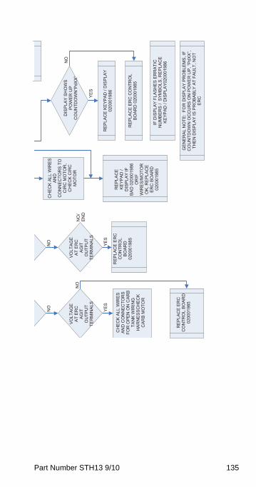
Part Number STH13 9/10 135
NO
NO
YES
NO
CH
EC
K A
LL W
IRES
AN
DC
ON
NEC
TOR
S TO
C
IRC
MO
TOR
, C
HEC
K C
IRC
M
OTO
R
DIS
PLA
Y S
HO
WS
POW
ER
UP
CO
UN
TDO
WN
“PdX
X”
VO
LTA
GE
AT
ER
C
AG
ITO
UTP
UT
TER
MIN
ALS
VO
LTA
GE
AT
ER
C
AG
ITO
UTP
UT
TER
MIN
ALS
NO
NO
/ EN
D
YES
YES
RE
PLA
CE
KE
YPAD
/ D
ISP
LAY
0200
0198
6R
EP
LAC
E E
RC
C
ON
TRO
LBO
ARD
0200
0198
5
RE
PLA
CE
KE
YPA
D /
DIS
PLA
Y IF
B
AD
020
0019
86O
RIF
WIR
ES/M
OTO
R
OK
, RE
PLA
CE
ERC
BO
ARD
02
0001
985
CH
EC
K A
LL W
IRES
AN
D C
ON
NEC
TOR
S FO
R O
PEN
ON
CAR
B TA
NK
WIR
ING
H
ARN
ESSC
HEC
KC
ARB
MO
TOR
REP
LAC
E ER
C C
ON
TRO
L B
OA
RD
020
0019
85
IF D
ISPL
AY F
LASH
ES E
RR
ATIC
N
UM
BE
RS
/ S
YMB
OLS
, RE
PLA
CE
KE
YPA
D /
DIS
PLA
Y020
0019
86
RE
PLA
CE
ER
C
CO
NTR
OL
BOAR
D
GEN
ERAL
NO
TE:
FOR
DIS
PLAY
PR
OBL
EMS,
IF
CO
UN
TDO
WN
OC
CU
RS
ON
PO
WE
R U
P, “P
dXX”
, TH
EN
DIS
PLA
Y IS
PR
OB
AB
LY A
T FA
ULT
, NO
T ER
C
0200
0198
5
STH13_Tech.book Page 135 Wednesday, September 15, 2010 3:20 PM

136 Part Number STH13 9/10
This Page Intentionally Left Blank
STH13_Tech.book Page 136 Wednesday, September 15, 2010 3:20 PM
Part Number STH13 9/10 137
Component Check Procedures
Head Pressure Control ValveMultiplex remote systems require head pressure control valves with special settings. Replace defective head pressure control valves only with “original” Multiplex replacement parts.
OPERATIONThe R404A head pressure control valve is non adjustable.
At ambient temperatures of approximately 70°F (21°C) or above, refrigerant flows through the valve from the condenser to the receiver inlet. At temperatures below this (or at higher temperatures if it is raining), the head pressure control dome’s nitrogen charge closes the condenser port and opens the bypass port from the compressor discharge line.
In this modulating mode, the valve maintains minimum head pressure by building up liquid in the condenser and bypassing discharge gas directly to the receiver.
DIAGNOSING1. Determine if the coil is clean. Air passes through
the condenser from the bottom up. Verify the coil is clean by looking from the bottom up. Do not look down through the fan.
2. Determine the air temperature entering the remote condenser.
3. Determine if the head pressure is high or low in relationship to the outside temperature. (Refer to the proper “Normal Operating Pressures of Refrigeration Units” in the Charts section.)
4. Determine the temperature of the liquid line entering the receiver by feeling it. This line is normally warm; “body temperature.”
5. Using the information gathered, refer to the chart below.
NOTE: A head pressure control valve that will not bypass, will function properly with condenser air temperatures of approximately 70°F (21°C) or above.
STH13_Tech.book Page 137 Wednesday, September 15, 2010 3:20 PM
138 Part Number STH13 9/10
When the temperature drops below 70°F (21°C), the head pressure control valve fails to bypass and the ice machine malfunctions. Lower ambient conditions can be simulated by rinsing the condenser with cool water during the freeze cycle.
FAN CYCLE CONTROL VS. HEAD PRESSURE CONTROL VALVEA fan cycle control cannot be used in place of a head pressure control valve. The fan cycle control is not capable of bypassing the condenser coil and keeping the liquid line temperature and pressure up.
This is very apparent when it rains or the outside temperature drops. When it rains or the outside temperature drops, the fan begins to cycle on and off. At first, everything appears normal. But, as it continues raining or getting colder, the fan cycle control can only turn the fan off. All the refrigerant must continue to flow through the condenser coil, being cooled by the rain or low outside temperature.
This causes excessive sub-cooling of the refrigerant. As a result, the liquid line temperature and pressure are not maintained for proper operation.
ConditionProbable
CauseCorrective Measure
Discharge Pressure - HighLiquid Line Temperature - Hot
Valve stuck in bypass
Replace valve
Discharge Pressure - LowLiquid Line Temperature - Cold
Valve not bypassing
Replace valve
Discharge Pressure - LowLiquid Line Temperature - Hot
Ice Machine Low on Charge
Low on Charge
Verification
STH13_Tech.book Page 138 Wednesday, September 15, 2010 3:20 PM
Part Number STH13 9/10 139
Charging Multiplex Remote Refrigeration Unit NOTE: System would have been opened for repairs. Once completed, a vacuum of 500 microns would have been maintained for 1/2 hour. The proper procedure for charging the system includes the reintroduction of all refrigerant that had been recovered before making the repair.
1. Attach charging hose of gauge manifold to liquid valve of the recovery cylinder (if no refrigerant was in the system, and thus, no refrigerant was recovered, attach charging hose to Refrigerant cylinder). Open cylinder valve.
2. Place cylinder on charging scale-zero scale.
3. Open high side valve wheel of gauge manifold. DO NOT ATTEMPT TO CHARGE SYSTEM ON LOW SIDE—CHARGE IN A LIQUID STATE ONLY WITH REFRIGERATION SYSTEM OFF.
4. Allow sufficient time for all refrigerant to transfer from cylinder to refrigeration unit. If necessary, put cylinder into bucket of hot water to increase the internal pressure of the cylinder.
5. System total charge is the net result of:
A. Refrigeration Unit charge on nameplate
B. Remote line set length X .72 oz./ft.
C. 90% of condenser volume (cu. ft.) x Refrigerant (wt./cu ft)
NOTE: Refrigerant weight varies with temperature. R-404A weighs 72 lb/cu. ft. @ 32°; 62 lb/cu. ft. @ 95°
6. When all refrigerant has been transferred, close valve wheel of the manifold.
7. Turn refrigeration unit on.
STH13_Tech.book Page 139 Wednesday, September 15, 2010 3:20 PM
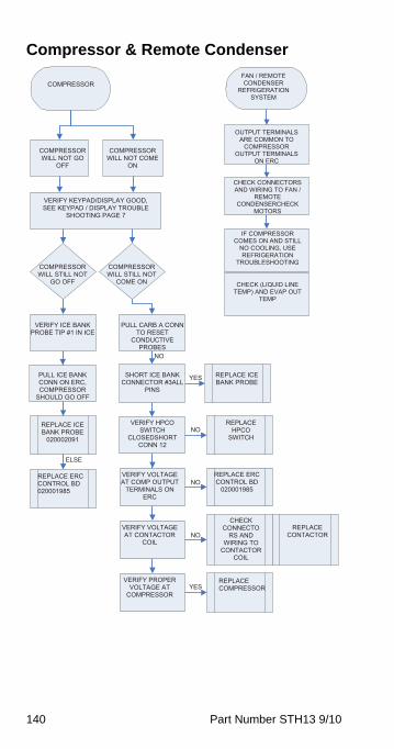
140 Part Number STH13 9/10
Compressor & Remote Condenser
COMPRESSOR
NO
NO
NO
YES
NO
COMPRESSORWILL NOT GO
OFF
COMPRESSORWILL NOT COME
ON
VERIFY KEYPAD/DISPLAY GOOD, SEE KEYPAD / DISPLAY TROUBLE
SHOOTING PAGE 7
COMPRESSORWILL STILL NOT
GO OFF
COMPRESSORWILL STILL NOT
COME ON
YES
ELSE
VERIFY ICE BANK PROBE TIP #1 IN ICE
PULL CARB A CONN TO RESET
CONDUCTIVE PROBES
PULL ICE BANK CONN ON ERC, COMPRESSOR
SHOULD GO OFF
SHORT ICE BANK CONNECTOR #3ALL
PINS
REPLACE ICE BANK PROBE
REPLACEHPCO
SWITCH
VERIFY HPCO SWITCH
CLOSEDSHORTCONN 12
REPLACE ICE BANK PROBE
020002091
REPLACE ERC CONTROL BD
020001985
VERIFY VOLTAGE AT COMP OUTPUT
TERMINALS ON ERC
REPLACE ERC CONTROL BD 020001985
CHECKCONNECTO
RS AND WIRING TO
CONTACTORCOIL
REPLACECONTACTOR
VERIFY VOLTAGE AT CONTACTOR
COIL
VERIFY PROPER VOLTAGE AT
COMPRESSOR
REPLACECOMPRESSOR
FAN / REMOTE CONDENSER
REFRIGERATIONSYSTEM
OUTPUT TERMINALS ARE COMMON TO
COMPRESSOROUTPUT TERMINALS
ON ERC
CHECK CONNECTORS AND WIRING TO FAN /
REMOTECONDENSERCHECK
MOTORS
IF COMPRESSOR COMES ON AND STILL
NO COOLING, USE REFRIGERATION
TROUBLESHOOTING
CHECK (LIQUID LINE TEMP) AND EVAP OUT
TEMP
STH13_Tech.book Page 140 Wednesday, September 15, 2010 3:20 PM
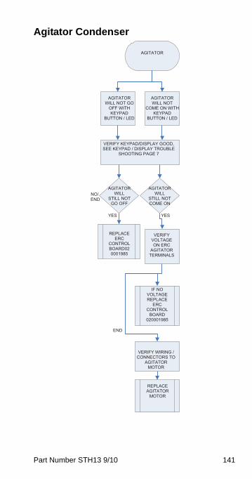
Part Number STH13 9/10 141
Agitator Condenser
AGITATOR
END
YESYES
NO/END
AGITATORWILL NOT GO
OFF WITH KEYPAD
BUTTON / LED
AGITATORWILL NOT
COME ON WITH KEYPAD
BUTTON / LED
VERIFY KEYPAD/DISPLAY GOOD, SEE KEYPAD / DISPLAY TROUBLE
SHOOTING PAGE 7
AGITATORWILL
STILL NOT COME ON
AGITATORWILL
STILL NOT GO OFF
REPLACEERC
CONTROLBOARD020001985
VERIFY VOLTAGE ON ERC
AGITATORTERMINALS
IF NO VOLTAGE REPLACE
ERCCONTROL
BOARD020001985
VERIFY WIRING / CONNECTORS TO
AGITATORMOTOR
REPLACEAGITATOR
MOTOR
STH13_Tech.book Page 141 Wednesday, September 15, 2010 3:20 PM
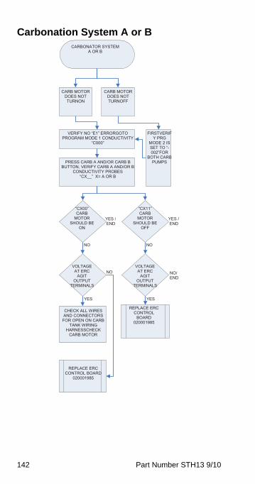
142 Part Number STH13 9/10
Carbonation System A or BCARBONATOR SYSTEM
A OR B
YES / END
NO
CARB MOTOR DOES NOT TURNON
CARB MOTOR DOES NOT TURNOFF
FIRSTVERIFY PRG
MODE 2 IS SET TO “-002”FOR
BOTH CARB PUMPS
VERIFY NO “E1” ERRORGOTO PROGRAM MODE 1 CONDUCTIVITY
“C000”
PRESS CARB A AND/OR CARB B BUTTON, VERIFY CARB A AND/OR B
CONDUCTIVITY PROBES
NO
“CX__” X= A OR B
“CX00” CARB
MOTORSHOULD BE
ON
“CX11” CARB
MOTORSHOULD BE
OFF
YES / END
VOLTAGE AT ERC
AGITOUTPUT
TERMINALS
VOLTAGE AT ERC
AGITOUTPUT
TERMINALS
NO NO/ END
YES YES
REPLACE ERC CONTROL
BOARD020001985
CHECK ALL WIRES AND CONNECTORS
FOR OPEN ON CARB TANK WIRING
HARNESSCHECKCARB MOTOR
REPLACE ERC CONTROL BOARD
020001985
STH13_Tech.book Page 142 Wednesday, September 15, 2010 3:20 PM
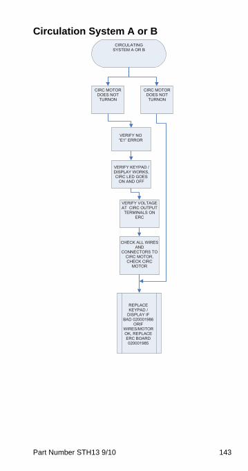
Part Number STH13 9/10 143
Circulation System A or BCIRCULATING
SYSTEM A OR B
CIRC MOTOR DOES NOT TURNON
CIRC MOTOR DOES NOT TURNON
VERIFY NO “E1” ERROR
VERIFY KEYPAD / DISPLAY WORKS, CIRC LED GOES
ON AND OFF
VERIFY VOLTAGE AT CIRC OUTPUT
TERMINALS ON ERC
CHECK ALL WIRES AND
CONNECTORS TO CIRC MOTOR, CHECK CIRC
MOTOR
REPLACEKEYPAD /
DISPLAY IF BAD 020001986
ORIFWIRES/MOTOR OK, REPLACE ERC BOARD 020001985
STH13_Tech.book Page 143 Wednesday, September 15, 2010 3:20 PM
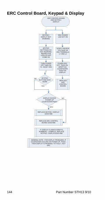
144 Part Number STH13 9/10
ERC Control Board, Keypad & DisplayERC CONTROL BOARD
AND KEYPAD / DISPLAY
KEYPAD / DISPLAY NOT
WORKING
ERC POWER LED NOT ON
KEYPAD BUTTON(S) DO NOT RESPOND,
RESPECTIVE LEDS DO NOT
COME ON
VERIFY PROPER VOLTAGE ON
ERC TERMINALS L1 AND L2
YES
NO
YES
NO
POWER ERC OFF, THEN ON,
VERIFY NO COUNTDOWN
“PdXX”ON DISPLAY
TURN POWER OFF THEN ON
TO RESET ERC
KEYPAD BUTTONS NOW
WORK REPLACE
ERCCONTROL
BOARD
DISPLAY SHOWS POWER UP
COUNTDOWN“PdXX”
REPLACE KEYPAD / DISPLAY 020001986
REPLACE ERC CONTROL BOARD 020001985
IF DISPLAY FLASHES ERRATIC NUMBERS / SYMBOLS, REPLACE
KEYPAD / DISPLAY020001986
GENERAL NOTE: FOR DISPLAY PROBLEMS, IF COUNTDOWN OCCURS ON POWER UP, “PdXX”, THEN DISPLAY IS PROBABLY AT FAULT, NOT
ERC
STH13_Tech.book Page 144 Wednesday, September 15, 2010 3:20 PM
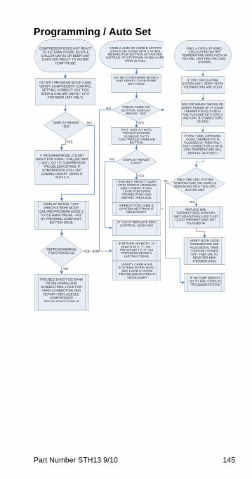
Part Number STH13 9/10 145
Programming / Auto Set
COMPRESSOR DOES NOT REACT TO ICE BANK PROBE (SODA &
CHILLER UNITS) OR BEER UNIT DOES NOT REACT TO WATER
TEMP PROBE
GO INTO PROGRAM MODE 3 AND VERIFY COMPRESSOR CONTROL
SETTING CORRECT“-003” FOR SODA & CHILLER UNITS(“-1273”
FOR BEER UNIT ONLY)
NO
YES
DISPLAY READS “-003”
F PROGRAM MODE 3 IS SET RIGHT FOR SODA / CHILLER UNIT
(“-003”), GO TO COMPRESSOR TROUBLESHOOTING, IF
COMPRESSOR STILL NOT COMING ON/OFF WHEN IT
SHOULD
DISPLAY READS “1273” WHICH IS BEER MODE
ONLYRE-PROGRAM MODE 3 TO ICE BANK PROBE “-003” BY PRESSING COMP/AGIT
BUTTON ONCE
YES / ENDREPROGRAMMINGFIXES PROBLEM
NO
TROUBLE SHOOT ICE BANK PROBE WIRING AND
CONNECTORS, LOOK FOR OPEN CONNECTION AND REPAIR / REPLACESEE
COMPRESSORTROUBLESHOOTING IF
CARB A AND/OR CARB B MOTOR STAYS ON CONSTANTLY WHEN
RESPECTIVE BUTTON ACTIVATED INSTEAD OF STOPPING WHEN CARB
TANK IS FULL
YES
YES
NO
NO
GO INTO PROGRAM MODE 2 AND VERIFY CARB PUMP
SETTINGS
PRESS CARB A/B BUTTON, DISPLAY
READS “-002”
EXIT, AND GO INTO PROGRAM MODE 1CONDUCTIVITY
“C001”PRESS CARB A/B BUTTON
DISPLAY READS “CAOO”
TROUBLE SHOOT CARB TANK WIRING HARNESS
AND CONNECTORS, LOOK FOR OPEN
CONNECTION AND REPAIR / REPLACE
REPEAT FOR CARB B SYSTEM SETTINGS IF
NECESSARY
IF “CA11” REPLACE ERC CONTROL 020001985
IF EITHER OR BOTH “0” DIGITS IS A “1”, RE-
PROGRAM TO “0” VIA PROGRAM MODE 2
INSTRUCTIONS
VERIFY CARB A & B SYSTEMS WORK NOW,
SEE CARB SYSTEM TROUBLESHOOTING IF
NECESSARY
ONLY A OR B (OR NONE) CIRCULATING WATER
TEMPERATURE DISPLAYED ON KEYPAD, UNIT HAS TWO CIRC
SYSTEM
YES
IF TWO CIRCULATING SYSTEM UNIT, VERIFY BOTH THERMISTORS ARE GOOD
ERC PROGRAM CHECKS ON EVERY POWER UP, IF GOOD
THERMISTOR(S) (0-200°F) ARE PLUGGED INTO CIRC A AND CIRC B CONNECTORS
ON ERC
IF ONLY ONE, (OR NONE) GOOD THERMISTOR IS
PLUGGED IN, THEN ONLY THAT CONNECTOR (A OR B) CIRC TEMPERATURE WILL
DISPLAY (AUTOSET)
ONLY ONE CIRC SYSTEM TEMPERATURE (OR NONE) IS DISPLAYING ON A TWO CIRC
SYSTEM UNIT
NO
REPLACE BAD THERMISTOR(S) 020001991
(NOT MEASURING 0-200°F) OR GOOD THERMISTOR(S) NOT
PLUGGED IN
VERIFY BOTH GOOD THERMISTORS ARE PLUGGED IN, THEN TURN UNIT POWER OFF, THEN ON, TO
REGISTER NEW THERMISTOR(S)
IF NO TEMP DISPLAY GO TO ERC / DISPLAY TROUBLESHOOTING
STH13_Tech.book Page 145 Wednesday, September 15, 2010 3:20 PM
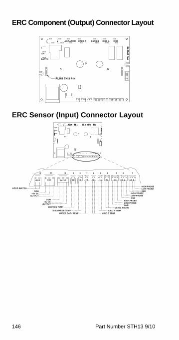
146 Part Number STH13 9/10
ERC Component (Output) Connector Layout
ERC Sensor (Input) Connector Layout
L
L/N
C R AGITATIOR CIRCB
CARB A CARB B CIRC A
EARTH
PLUG THIS PIN
12 11 10 9 8 7 6 5 4 3 2 1
CO2 TS TD TW TB TA WL ICE CA A CA B HPCO WATER
HIGH PROBE HPCO SWITCH LOW PROBE
COMHIGH PROBE
GND+5V DC
LOW PROBE OUTPUT
COM HIGH PROBE GND
+5V DC LOW PROBE OUTPUTSUCTION TEMP LEVEL PROBE
GND
DISCHARGE TEMPCIRC B TEMP
CIRC A TEMP WATER BATH TEMP
STH13_Tech.book Page 146 Wednesday, September 15, 2010 3:20 PM
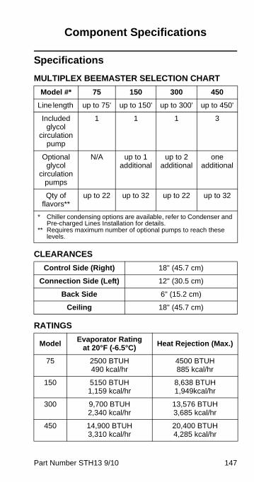
Part Number STH13 9/10 147
Component Specifications
Specifications
MULTIPLEX BEEMASTER SELECTION CHART
CLEARANCES
RATINGS
Model #* 75 150 300 450
Line length up to 75' up to 150' up to 300' up to 450'
Included glycol
circulation pump
1 1 1 3
Optional glycol
circulation pumps
N/A up to 1 additional
up to 2 additional
one additional
Qty of flavors**
up to 22 up to 32 up to 22 up to 32
* Chiller condensing options are available, refer to Condenser and Pre-charged Lines Installation for details.
** Requires maximum number of optional pumps to reach these levels.
Control Side (Right) 18" (45.7 cm)
Connection Side (Left) 12" (30.5 cm)
Back Side 6" (15.2 cm)
Ceiling 18" (45.7 cm)
ModelEvaporator Rating
at 20°F (-6.5°C)Heat Rejection (Max.)
75 2500 BTUH490 kcal/hr
4500 BTUH885 kcal/hr
150 5150 BTUH1,159 kcal/hr
8,638 BTUH1,949kcal/hr
300 9,700 BTUH 2,340 kcal/hr
13,576 BTUH 3,685 kcal/hr
450 14,900 BTUH3,310 kcal/hr
20,400 BTUH4,285 kcal/hr
STH13_Tech.book Page 147 Wednesday, September 15, 2010 3:20 PM
148 Part Number STH13 9/10
NOTE: Refer to serial plate on front of refrigeration unit for voltage and amperage specifications. Make all electrical connections at the junction box located at the top rear of unit. Optional equipment may require additional power supplies.
! WarningCarbon Dioxide (CO2) displaces oxygen.Exposure to a high concentration of CO2 gascauses tremors, which are followed rapidly byloss of consciousness and suffocation. If a CO2gas leak is suspected, particularly in a small area,immediately ventilate the area before repairingthe leak. CO2 lines and pumps must not beinstalled in an enclosed space. An enclosedspace can be a cooler or small room or closet.This may include convenience stores with glassdoor self serve coolers. If you suspect CO2 maybuild up in an area, venting of the BIB pumpsand/or CO2 monitors must be utilized.
STH13_Tech.book Page 148 Wednesday, September 15, 2010 3:20 PM
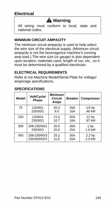
Part Number STH13 9/10 149
Electrical
MINIMUM CIRCUIT AMPACITYThe minimum circuit ampacity is used to help select the wire size of the electrical supply. (Minimum circuit ampacity is not the beverage/ice machine’s running amp load.) The wire size (or gauge) is also dependent upon location, materials used, length of run, etc., so it must be determined by a qualified electrician.
ELECTRICAL REQUIREMENTSRefer to Ice Machine Model/Serial Plate for voltage/amperage specifications.
SPECIFICATIONS
! WarningAll wiring must conform to local, state andnational codes.
ModelVolt/Cycle/
Phase
Minimum Circuit Amps
Breaker Compressor
75 120/601230/50/1
20.39.0
25A16A
1/3 hp.46 kW
150 120/601230/50/1
21.510.7
30A16A
12 hp.97 kW
300 208-230/60/1230/50/1
20.620.6
30A25A
1 hp1.9 kW
450 208-230/60/3230/400/50/3
25.211.6
30A20A
2.2 hp2.0 kW
STH13_Tech.book Page 149 Wednesday, September 15, 2010 3:20 PM

150 Part Number STH13 9/10
This Page Intentionally Left Blank
STH13_Tech.book Page 150 Wednesday, September 15, 2010 3:20 PM
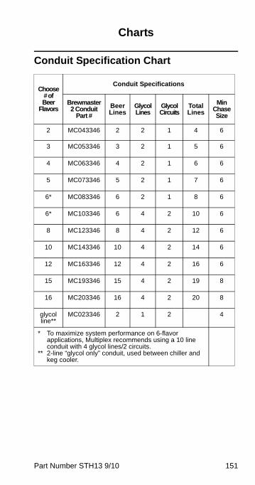
Part Number STH13 9/10 151
Charts
Conduit Specification Chart
Choose # of Beer
Flavors
Conduit Specifications
Brewmaster 2 Conduit
Part #
Beer Lines
Glycol Lines
Glycol Circuits
Total Lines
Min Chase Size
2 MC043346 2 2 1 4 6
3 MC053346 3 2 1 5 6
4 MC063346 4 2 1 6 6
5 MC073346 5 2 1 7 6
6* MC083346 6 2 1 8 6
6* MC103346 6 4 2 10 6
8 MC123346 8 4 2 12 6
10 MC143346 10 4 2 14 6
12 MC163346 12 4 2 16 6
15 MC193346 15 4 2 19 8
16 MC203346 16 4 2 20 8
glycol line**
MC023346 2 1 2 4
* To maximize system performance on 6-flavor applications, Multiplex recommends using a 10 line conduit with 4 glycol lines/2 circuits.
** 2-line “glycol only” conduit, used between chiller and keg cooler.
STH13_Tech.book Page 151 Wednesday, September 15, 2010 3:20 PM
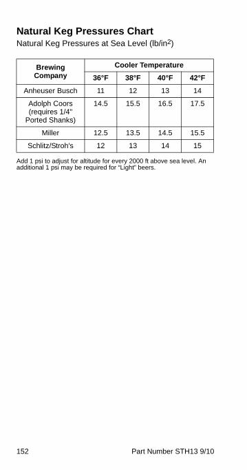
152 Part Number STH13 9/10
Natural Keg Pressures ChartNatural Keg Pressures at Sea Level (lb/in2)
Add 1 psi to adjust for altitude for every 2000 ft above sea level. An additional 1 psi may be required for “Light” beers.
Brewing Company
Cooler Temperature
36°F 38°F 40°F 42°F
Anheuser Busch 11 12 13 14
Adolph Coors (requires 1/4"
Ported Shanks)
14.5 15.5 16.5 17.5
Miller 12.5 13.5 14.5 15.5
Schlitz/Stroh's 12 13 14 15
STH13_Tech.book Page 152 Wednesday, September 15, 2010 3:20 PM
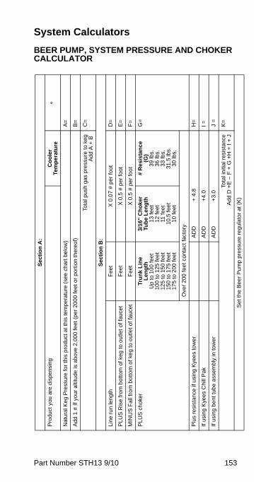
Part Number STH13 9/10 153
System Calculators
BEER PUMP, SYSTEM PRESSURE AND CHOKER CALCULATOR
Sec
tio
n A
:
Pro
duc
t yo
u a
re d
ispe
nsin
gC
oo
ler
Tem
pe
ratu
re°
Nat
ura
l Ke
g P
ress
ure
for
this
pro
duct
at
this
tem
pera
ture
(se
e c
hart
be
low
) A
=
Ad
d 1
# I
f yo
ur a
ltitu
de
is a
bove
2,0
00
feet
(p
er 2
000
feet
or
po
rtio
n t
here
of)
B=
Tota
l pus
h ga
s pr
essu
re t
o ke
gA
dd
A +
B
C=
Sec
tio
n B
:
Lin
e ru
n le
ngt
h
Fe
et
X 0
.07
# p
er
foo
t D
=
PL
US
Ris
e fr
om
bot
tom
of k
eg
to o
utle
t of f
auce
t F
eet
X
0.5
# p
er f
oot
E
=
MIN
US
Fa
ll fr
om
bo
ttom
of k
eg
to o
utle
t of
fau
cet
Fe
et
X 0
.5 #
per
fo
ot
F=
PLU
S c
hoke
r T
run
k L
ine
Len
gth
Up
to 1
00
feet
100
to 1
25 f
eet
125
to 1
50 f
eet
150
to 1
75 f
eet
175
to 2
00 f
eet
3/1
6"
Ch
ok
er
Tub
e L
eng
th1
3 fe
et
12
fee
t11
feet
10.5
fee
t1
0 fe
et
# R
esi
sta
nc
e(G
)39
lbs.
36 lb
s.33
lbs.
31.
5 lb
s.30
lbs.
G=
Ove
r 2
00 fe
et c
onta
ct fa
ctor
y
Plu
s re
sist
anc
e if
usi
ng
Kye
es
tow
er
AD
D+
4.8
H
=
If us
ing
Kye
es C
hill
Pak
A
DD
+4
.0
I =
If u
sing
ben
t tu
be a
ssem
bly
in to
wer
AD
D+
3.0
J
=
Tota
l in
itial
res
ista
nce
Add
D +
E –
F +
G +
H +
I +
JK
=
Se
t th
e B
eer
Pum
p p
ress
ure
reg
ulat
or
at (
K)
STH13_Tech.book Page 153 Wednesday, September 15, 2010 3:20 PM
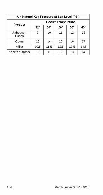
154 Part Number STH13 9/10
A = Natural Keg Pressure at Sea Level (PSI)
ProductCooler Temperature
32° 34° 26° 38° 40°
Anheuser-Busch
9 10 11 12 13
Coors 13 14 15 16 17
Miller 10.5 11.5 12.5 13.5 14.5
Schlitz / Stroh’s 10 11 12 13 14
STH13_Tech.book Page 154 Wednesday, September 15, 2010 3:20 PM
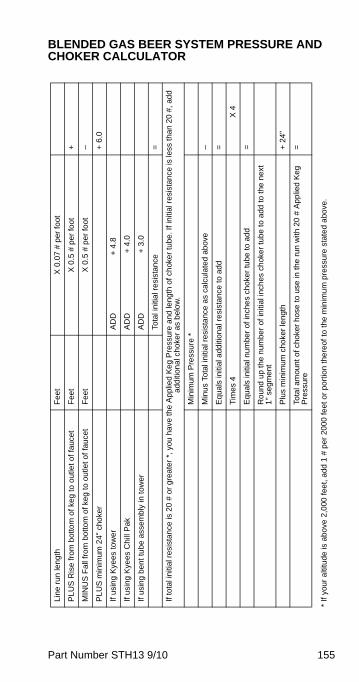
Part Number STH13 9/10 155
BLENDED GAS BEER SYSTEM PRESSURE AND CHOKER CALCULATOR
* If
you
r a
ltitu
de
is a
bo
ve 2
,000
fee
t, a
dd 1
# p
er 2
000
fee
t or
port
ion
the
reof
to
the
min
imu
m p
ress
ure
sta
ted
abo
ve.
Lin
e ru
n le
ngt
h
Fe
et
X 0
.07
# p
er fo
ot
PL
US
Ris
e fr
om
bo
ttom
of k
eg
to o
utle
t of
fauc
et
Fe
et
X 0
.5 #
pe
r fo
ot
+
MIN
US
Fa
ll fr
om
bo
ttom
of k
eg
to o
utle
t of
fau
cet
Fe
et
X 0
.5 #
pe
r fo
ot
–
PL
US
min
imum
24"
cho
ker
+ 6
.0
If u
sing
Kye
es t
ower
A
DD
+ 4
.8
If us
ing
Kye
es C
hill
Pak
A
DD
+ 4
.0
If u
sin
g b
ent
tub
e a
ssem
bly
in to
wer
AD
D +
3.0
Tota
l ini
tial r
esis
tanc
e =
If to
tal i
nitia
l res
ista
nce
is 2
0 #
or
grea
ter
*, y
ou h
ave
the
Ap
plie
d K
eg
Pre
ssu
re a
nd
len
gth
of c
hok
er
tube
. If i
nitia
l res
ista
nce
is le
ss th
an 2
0 #
, ad
d
addi
tion
al c
hok
er
as b
elo
w.
Min
imum
Pre
ssur
e *
Min
us
Tota
l in
itia
l res
ista
nce
as
calc
ula
ted
ab
ove
–
Eq
uals
initi
al a
dditi
ona
l re
sist
anc
e to
ad
d =
Tim
es
4
X 4
Eq
uals
initi
al n
umbe
r of
inch
es
cho
ker
tube
to a
dd
=
Ro
und
up
the
num
ber
of in
itial
inch
es c
hok
er
tub
e to
add
to t
he n
ext
1
" se
gmen
t
Plu
s m
inim
um
cho
ker
len
gth
+ 2
4"
Tota
l am
ount
of
chok
er
hose
to
use
in t
he r
un w
ith 2
0 #
Ap
plie
d K
eg
Pre
ssur
e=
STH13_Tech.book Page 155 Wednesday, September 15, 2010 3:20 PM
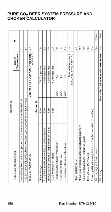
156 Part Number STH13 9/10
PURE CO2 BEER SYSTEM PRESSURE AND CHOKER CALCULATOR
Se
ctio
n A
:
Pro
du
ct y
ou
are
dis
pen
sing
Co
ole
r Te
mp
era
ture
°N
atu
ral K
eg
Pre
ssur
e fo
r th
is p
rod
uct
at t
his
tem
per
atu
re (
see
char
t bel
ow
) A
=
Add
1 #
If
you
r al
titu
de is
ab
ove
2,0
00 fe
et (
pe
r 20
00 fe
et o
r po
rtio
n th
ere
of)
B
=
Tota
l Gas
Pus
h P
ress
ure
US
E T
HIS
AS
YO
UR
KE
G P
RE
SS
UR
EA
dd
A +
BC
=
Se
ctio
n B
:
Line
run
leng
th
Fee
t X
0.0
7 #
per
fo
ot
D=
PLU
S R
ise
fro
m b
otto
m o
f ke
g to
ou
tlet
of f
auce
t F
eet
X 0
.5 #
per
foot
E
=
MIN
US
Fal
l fro
m b
otto
m o
f ke
g to
ou
tlet
of f
auce
tF
eet
X 0
.5 #
per
foot
F
=
PLU
S m
inim
um
24
" ch
oke
r F
eet
X 3
.0 #
per
foot
G
=
Plu
s re
sist
an
ce if
usi
ng
Kye
es to
we
rA
DD
+4.
8
H=
If u
sin
g K
yee
s C
hill
Pa
k A
DD
+4.
0
I =
If u
sing
be
nt t
ube
ass
embl
y in
tow
erA
DD
+3.
0 J
=
Tota
l in
itial
res
ista
nce
Ad
d D
+ E
- F
+ G
+ H
+ I
+ J
K=
Idea
l Res
ista
nce
(C
)L
=
Min
us T
ota
l ini
tial r
esis
tan
ce a
s ca
lcul
ated
abo
ve (
K)
M =
Equ
als
initi
al a
ddi
tion
al r
esis
tan
ce to
add
N =
Take
val
ue o
f (N
) T
imes
4O
=
Ro
und
up
(O)
to th
e n
ext
foo
t (i.e
. 15
inch
es,
roun
d u
p to
two
fee
t)P
=
Add
the
orig
inal
2 fe
et c
hok
er
Q =
2
Fee
t
Add
P +
Q
Th
is i
s th
e to
tal
amo
un
t o
f ch
oke
r to
use
R =
F
eet
STH13_Tech.book Page 156 Wednesday, September 15, 2010 3:20 PM
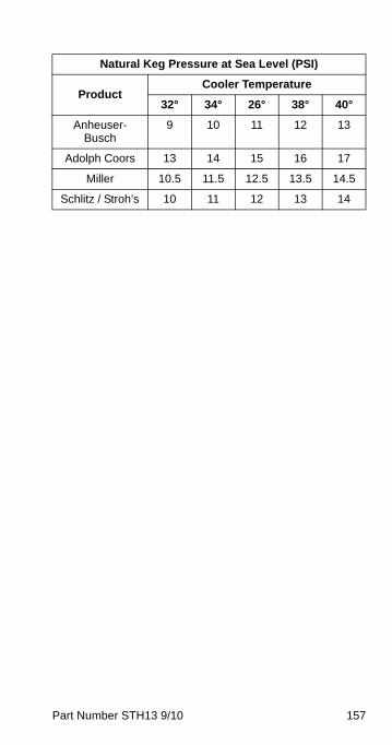
Part Number STH13 9/10 157
Natural Keg Pressure at Sea Level (PSI)
ProductCooler Temperature
32° 34° 26° 38° 40°
Anheuser-Busch
9 10 11 12 13
Adolph Coors 13 14 15 16 17
Miller 10.5 11.5 12.5 13.5 14.5
Schlitz / Stroh’s 10 11 12 13 14
STH13_Tech.book Page 157 Wednesday, September 15, 2010 3:20 PM

158 Part Number STH13 9/10
This Page Intentionally Left Blank
STH13_Tech.book Page 158 Wednesday, September 15, 2010 3:20 PM
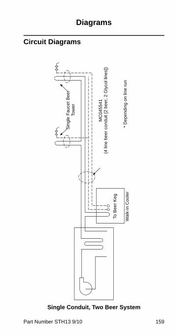
Part Number STH13 9/10 159
Diagrams
Circuit Diagrams
Single Conduit, Two Beer System
Wal
k-in
Co
ole
r
To B
eer
Ke
g
Sin
gle
Fa
uce
t B
ee
r To
we
r
MC
045
54
1(4
lin
e b
ee
r co
ndu
it [2
be
er,
2 G
lyco
l lin
es]
)
* D
epe
ndi
ng
on
lin
e ru
n
STH13_Tech.book Page 159 Wednesday, September 15, 2010 3:20 PM
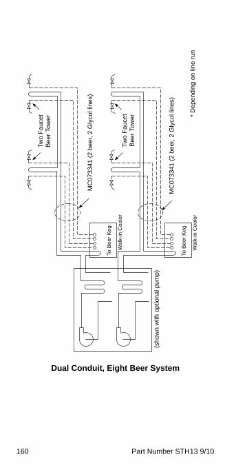
160 Part Number STH13 9/10
Dual Conduit, Eight Beer System
(sh
ow
n w
ith o
ptio
nal
pu
mp
)
Tw
o F
au
cet
Be
er
Tow
er
MC
07
334
1 (
2 b
eer
, 2
Gly
col l
ine
s)
MC
073
341
(2
be
er,
2 G
lyco
l lin
es)
Wal
k-in
Coo
ler
To B
ee
r K
eg
Wa
lk-i
n C
ool
er
To B
eer
Keg
Two
Fa
ucet
B
eer
Tow
er * D
epe
ndi
ng
on
lin
e ru
n
STH13_Tech.book Page 160 Wednesday, September 15, 2010 3:20 PM
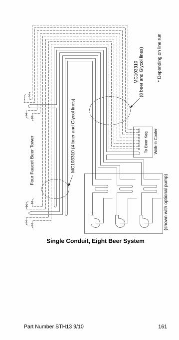
Part Number STH13 9/10 161
Single Conduit, Eight Beer System
Fou
r F
au
cet
Be
er
Tow
er
MC
10
331
0 (
4 b
eer
an
d G
lyco
l lin
es)
(sh
ow
n w
ith o
ptio
nal
pu
mp
)
Wa
lk-in
Coo
ler
To B
eer
Keg
MC
103
31
0 (8
be
er a
nd
Gly
col l
ine
s)
* D
epe
nd
ing
on
lin
e ru
n
STH13_Tech.book Page 161 Wednesday, September 15, 2010 3:20 PM
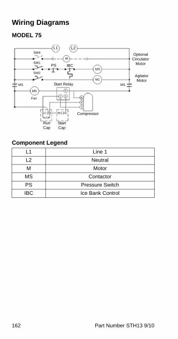
162 Part Number STH13 9/10
Wiring Diagrams
MODEL 75
Component Legend
L1 Line 1
L2 Neutral
M Motor
MS Contactor
PS Pressure Switch
IBC Ice Bank Control
Optional Circulator
Motor
Agitator Motor
IBC
L1
M
M1
SW4
SW1
SW2
MS Start Relay
L2
PSMS
M5
Fan
MS
Compressor
Start Cap
Run Cap
STH13_Tech.book Page 162 Wednesday, September 15, 2010 3:20 PM
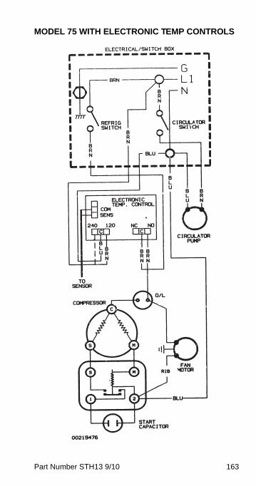
Part Number STH13 9/10 163
MODEL 75 WITH ELECTRONIC TEMP CONTROLS
STH13_Tech.book Page 163 Wednesday, September 15, 2010 3:20 PM
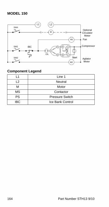
164 Part Number STH13 9/10
MODEL 150
Component Legend
L1 Line 1
L2 Neutral
M Motor
MS Contactor
PS Pressure Switch
IBC Ice Bank Control
Optional Circulator
Motor
Agitator Motor
CompressorIBC
L1 L2
M
M2
M1
SW4
SW1
SW2
O/L
Fan
Start
STH13_Tech.book Page 164 Wednesday, September 15, 2010 3:20 PM
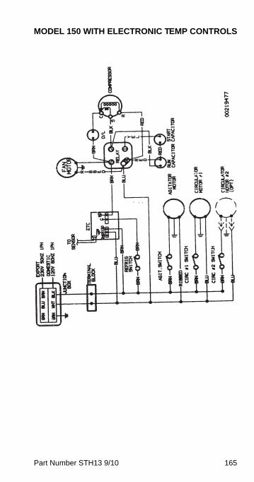
Part Number STH13 9/10 165
MODEL 150 WITH ELECTRONIC TEMP CONTROLS
STH13_Tech.book Page 165 Wednesday, September 15, 2010 3:20 PM
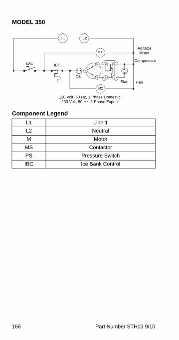
166 Part Number STH13 9/10
MODEL 350
Component Legend
L1 Line 1
L2 Neutral
M Motor
MS Contactor
PS Pressure Switch
IBC Ice Bank Control
Agitator Motor
CompressorIBC
L1 L2
M2
M1
SW1
O/L
FanStart
120 Volt, 60 Hz, 1 Phase Domestic230 Volt, 50 Hz, 1 Phase Export
STH13_Tech.book Page 166 Wednesday, September 15, 2010 3:20 PM
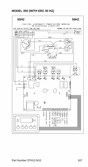
Part Number STH13 9/10 167
MODEL 350 (WITH ERC 50 HZ)
50HZ 50HZ
STH13_Tech.book Page 167 Wednesday, September 15, 2010 3:20 PM
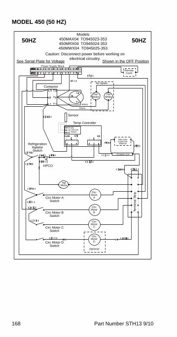
168 Part Number STH13 9/10
MODEL 450 (50 HZ)
50HZ 50HZModels
450MAX04 TO945023-353450MRX04 TO945024-353450MWX04 TO945025-353
Caution: Disconnect power before working on electrical circuitry.
See Serial Plate for Voltage Shown in the OFF PositionPower Supply Block
Remote Cond
(Black)
(Black)
ContactorAir Option
Fan Motor
Refrigeration Agitator Switch
Term
inal
Str
ipCirc Motor
ACirc Motor A Switch
HPCO
Optional
Fan Motor
Sensor
Agt Motor
Contactor Coil
RMT Only Liquid Line Solenoid
Temp Controller
Circ Motor
B
Circ Motor
C
Circ Motor
D
Circ Motor B Switch
Circ Motor C Switch
Circ Motor D Switch
BINCommonSensor
STH13_Tech.book Page 168 Wednesday, September 15, 2010 3:20 PM
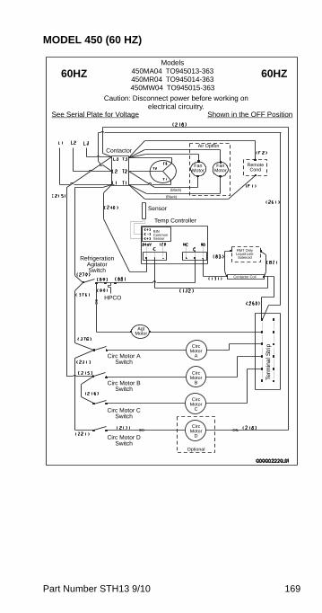
Part Number STH13 9/10 169
MODEL 450 (60 HZ)
60HZ 60HZModels
450MA04 TO945013-363450MR04 TO945014-363450MW04 TO945015-363
Caution: Disconnect power before working on electrical circuitry.
See Serial Plate for Voltage Shown in the OFF Position
Remote Cond
(Black)
(Black)
ContactorAir Option
Fan Motor
Refrigeration Agitator Switch
Term
inal
Str
ipCirc Motor
ACirc Motor A Switch
HPCO
Optional
Fan Motor
Sensor
Agt Motor
Contactor Coil
RMT Only Liquid Line Solenoid
Temp Controller
Circ Motor
B
Circ Motor
C
Circ Motor
D
Circ Motor B Switch
Circ Motor C Switch
Circ Motor D Switch
BINCommonSensor
STH13_Tech.book Page 169 Wednesday, September 15, 2010 3:20 PM
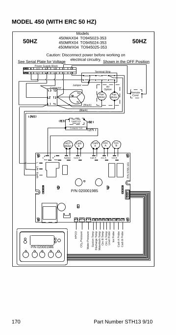
170 Part Number STH13 9/10
MODEL 450 (WITH ERC 50 HZ)
50HZ 50HZ
Models450MAX04 TO945023-353450MRX04 TO945024-353450MWX04 TO945025-353
Caution: Disconnect power before working on electrical circuitry.See Serial Plate for Voltage Shown in the OFF Position
Power Supply Block
Terminal Strip
Remote Cond
Air Option
Fan Motor
Fan Motor
(Black)
(Black)
Contactor
Contactor Coil
RMT Only Liquid Line Solenoid
AGT Motor
P/N 020001985
Jumper
Carb A
Carb A
Circ A
Circ B
Agitator Carb A Carb A Circ A Circ B
P/N 020001986
HP
CO
CO
2 P
ress
ure
Wa
ter
Pre
ssu
re
Su
ctio
n T
em
pD
isch
arg
e T
em
pW
ate
rba
th T
em
pC
irc
B T
em
p
Cir
c A
Te
mp
Le
vel P
rob
e
Ice
Pro
be
Ca
rb A
Pro
be
Ca
rb B
Pro
be
P/N
07
05
-10
1
Earth
RC
L/N
L
STH13_Tech.book Page 170 Wednesday, September 15, 2010 3:20 PM
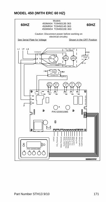
Part Number STH13 9/10 171
MODEL 450 (WITH ERC 60 HZ)
60HZ 60HZModels
450MA04 TO945013E-363450MR04 TO945014E-363450MW04 TO945015E-363
Caution: Disconnect power before working on electrical circuitry.
See Serial Plate for Voltage Shown in the OFF Position
Remote Cond
Air Option
Fan Motor
Fan Motor
(Black)(Black)
Contactor
Contactor Coil
RMT Only Liquid Line Solenoid
AGT Motor
P/N 020001985
Carb A
Carb A
Circ A
Circ B
Agitator Carb A Carb A Circ A Circ B
P/N 020001986
HP
CO
CO
2 P
ress
ure
Wa
ter
Pre
ssur
e
Su
ctio
n T
em
pD
isch
arg
e T
em
pW
ate
rba
th T
em
pC
irc
B T
em
p
Cir
c A
Te
mp
Le
vel P
rob
e
Ice
Pro
be
Ca
rb A
Pro
be
Ca
rb B
Pro
be
P/N
07
05
-10
1
Earth
RC
L/N
L
STH13_Tech.book Page 171 Wednesday, September 15, 2010 3:20 PM

172 Part Number STH13 9/10
This Page Intentionally Left Blank
STH13_Tech.book Page 172 Wednesday, September 15, 2010 3:20 PM

STH13_Tech.book Page 173 Wednesday, September 15, 2010 3:20 PM

Manitowoc Foodservice2100 Future Drive
Sellersburg, IN 47172, USAPh: 812-246-7000 Fax: 812-246-7024
Visit us online at: www.manitowocfsg.com
© 2010 ManitowocPart Number STH13 9/10
STH13_Tech.book Page 174 Wednesday, September 15, 2010 3:20 PM