Embed Size (px)
Citation preview

1 © 2008 Bernd Bruegge Software Engineering I: Software Technology WS 2008/9
Software Engineering I: Software Technology
WS 2008/09
Refresher Course UML I
Prof. Bernd Bruegge, Ph.D. Hans Breidler
Applied Software Engineering Technische Universitaet Muenchen
2 © 2008 Bernd Bruegge Software Engineering I: Software Technology WS 2008/9
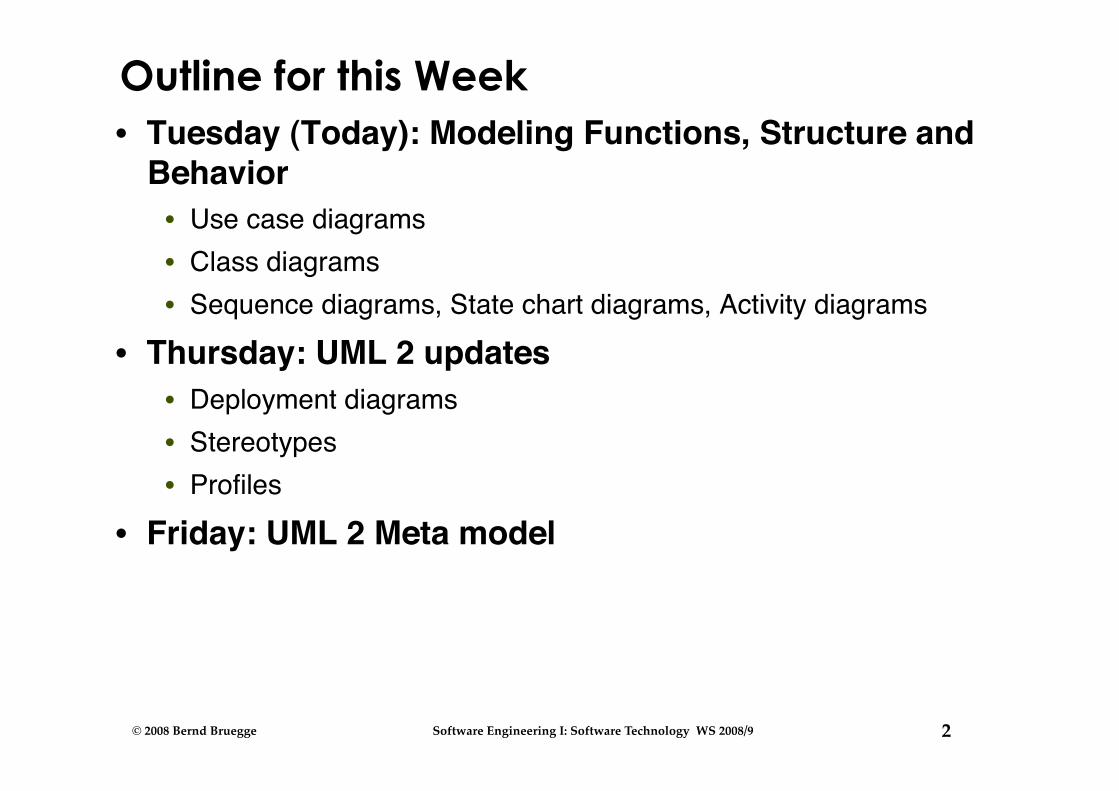
Outline for this Week • Tuesday (Today): Modeling Functions, Structure and
Behavior • Use case diagrams • Class diagrams • Sequence diagrams, State chart diagrams, Activity diagrams
• Thursday: UML 2 updates • Deployment diagrams • Stereotypes • Profiles
• Friday: UML 2 Meta model
3 © 2008 Bernd Bruegge Software Engineering I: Software Technology WS 2008/9
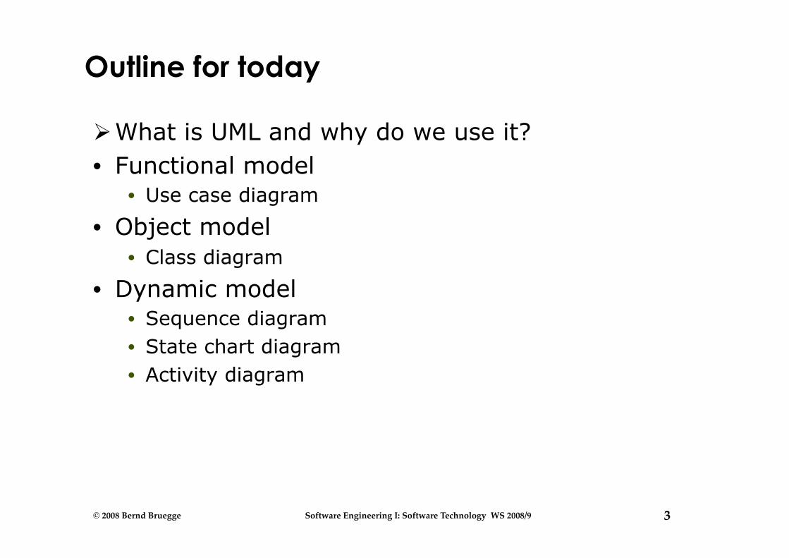
Outline for today
What is UML and why do we use it? • Functional model
• Use case diagram
• Object model • Class diagram
• Dynamic model • Sequence diagram • State chart diagram • Activity diagram

4 © 2008 Bernd Bruegge Software Engineering I: Software Technology WS 2008/9
What is UML?
• UML (Unified Modeling Language) • Convergence of notations used in object-oriented methods
• OMT (James Rumbaugh and colleagues) • Booch (Grady Booch) • OOSE (Ivar Jacobson)
• Current version 2.1.2 • Information at the UML portal http://www.uml.org/
• Commercial CASE tools: Rational Rose (IBM), Together (Borland), Visual Architect (business processes, BCD)
• Open Source CASE tools: ArgoUML, StarUML, Umbrello • Commercial as well as Open Source: PoseidonUML
(Gentleware)
5 © 2008 Bernd Bruegge Software Engineering I: Software Technology WS 2008/9
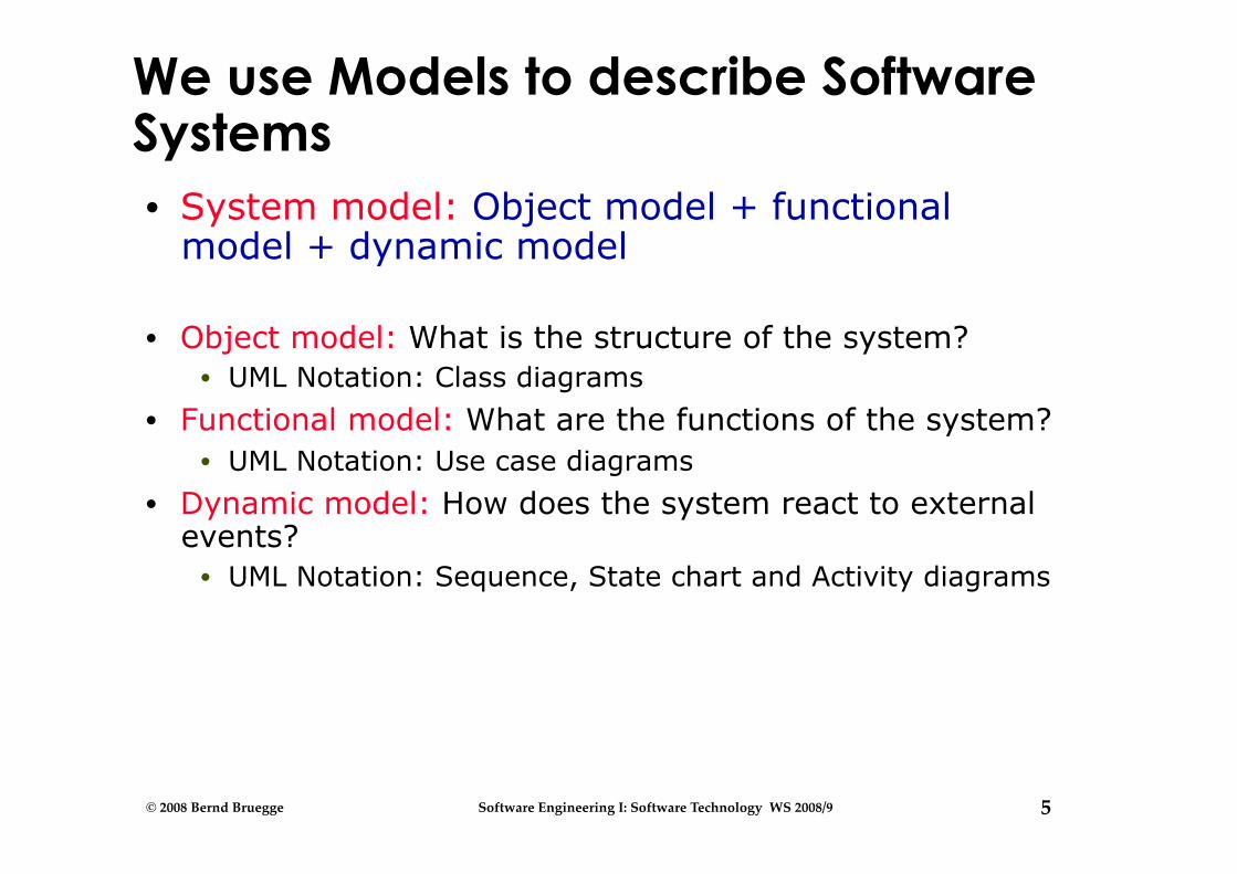
We use Models to describe Software Systems • System model: Object model + functional
model + dynamic model
• Object model: What is the structure of the system? • UML Notation: Class diagrams
• Functional model: What are the functions of the system? • UML Notation: Use case diagrams
• Dynamic model: How does the system react to external events?
• UML Notation: Sequence, State chart and Activity diagrams
6 © 2008 Bernd Bruegge Software Engineering I: Software Technology WS 2008/9
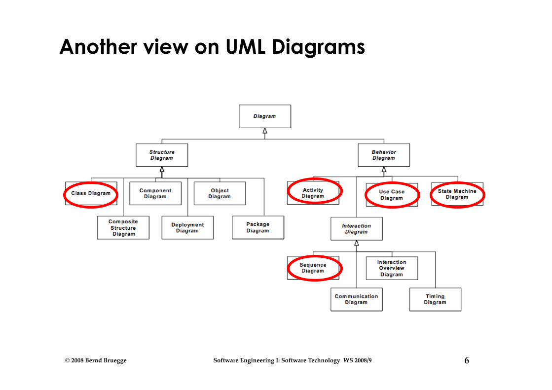
Another view on UML Diagrams

7 © 2008 Bernd Bruegge Software Engineering I: Software Technology WS 2008/9
Outline for today
What is UML and why do we use it? Functional model
Use case diagram
• Object model • Class diagram
• Dynamic model • Sequence diagram • State chart diagram • Activity diagram
8 © 2008 Bernd Bruegge Software Engineering I: Software Technology WS 2008/9
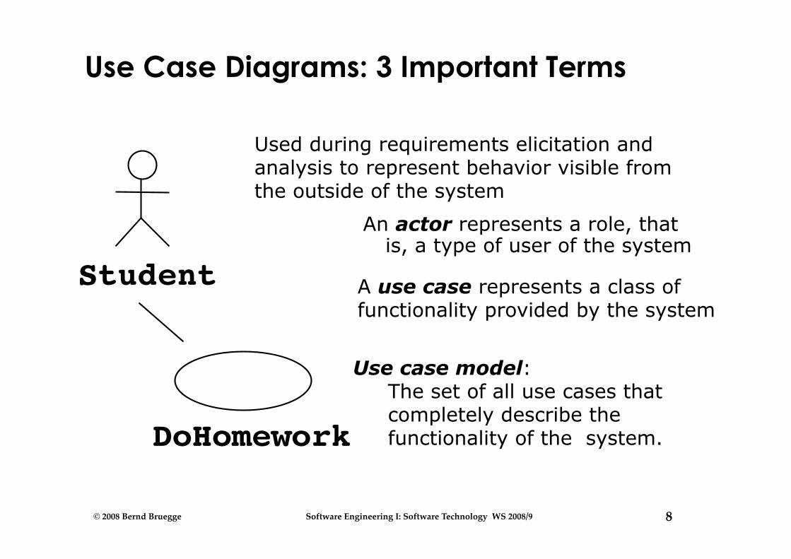
Use Case Diagrams: 3 Important Terms
An actor represents a role, that is, a type of user of the system
Student
DoHomework
Used during requirements elicitation and analysis to represent behavior visible from the outside of the system
Use case model: The set of all use cases that completely describe the functionality of the system.
A use case represents a class of functionality provided by the system

9 © 2008 Bernd Bruegge Software Engineering I: Software Technology WS 2008/9
Actor
• An actor is a model for an external entity which interacts with the system:
• EndUser, Administrator • External system (Another system) • Physical environment (e.g. Weather)
• An actor has a unique name and an optional description
• Examples: • Student: A studying person • Teaching Assistant: Member of
teaching staff who supports the instructor.
• Random Number generator
Student
Name
Optional Description
10 © 2008 Bernd Bruegge Software Engineering I: Software Technology WS 2008/9
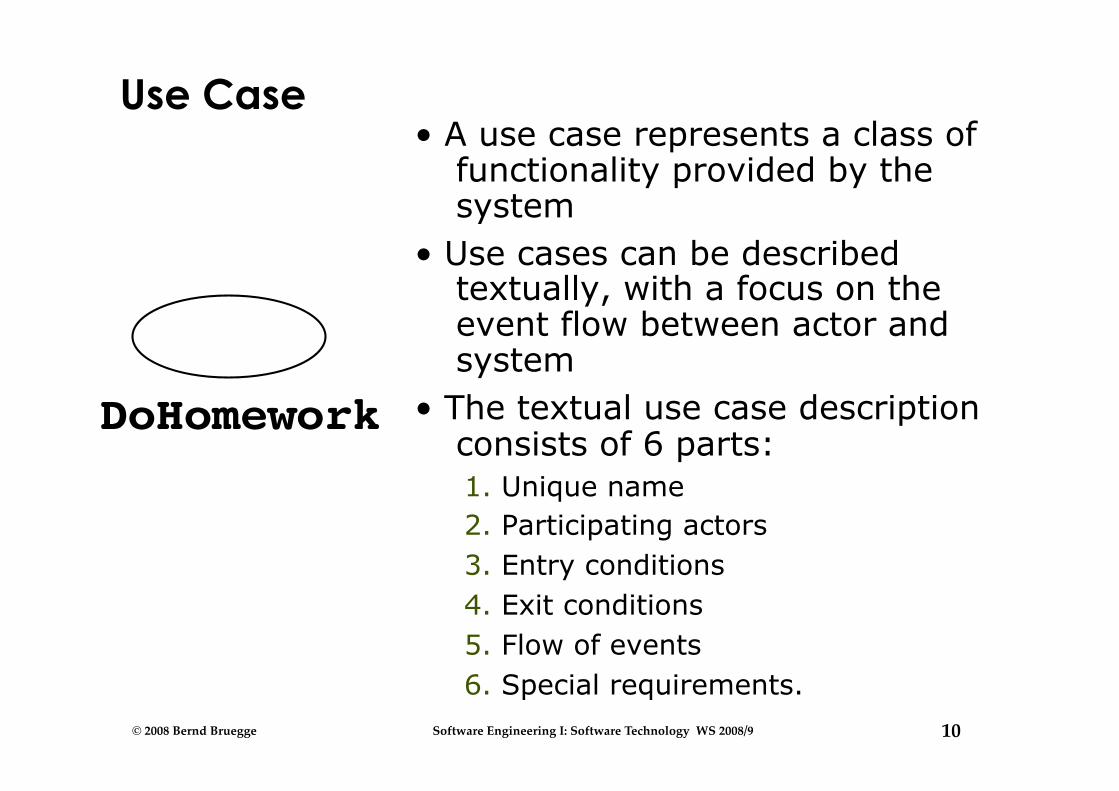
Use Case • A use case represents a class of
functionality provided by the system
• Use cases can be described textually, with a focus on the event flow between actor and system
• The textual use case description consists of 6 parts: 1. Unique name 2. Participating actors 3. Entry conditions 4. Exit conditions 5. Flow of events 6. Special requirements.
DoHomework
11 © 2008 Bernd Bruegge Software Engineering I: Software Technology WS 2008/9
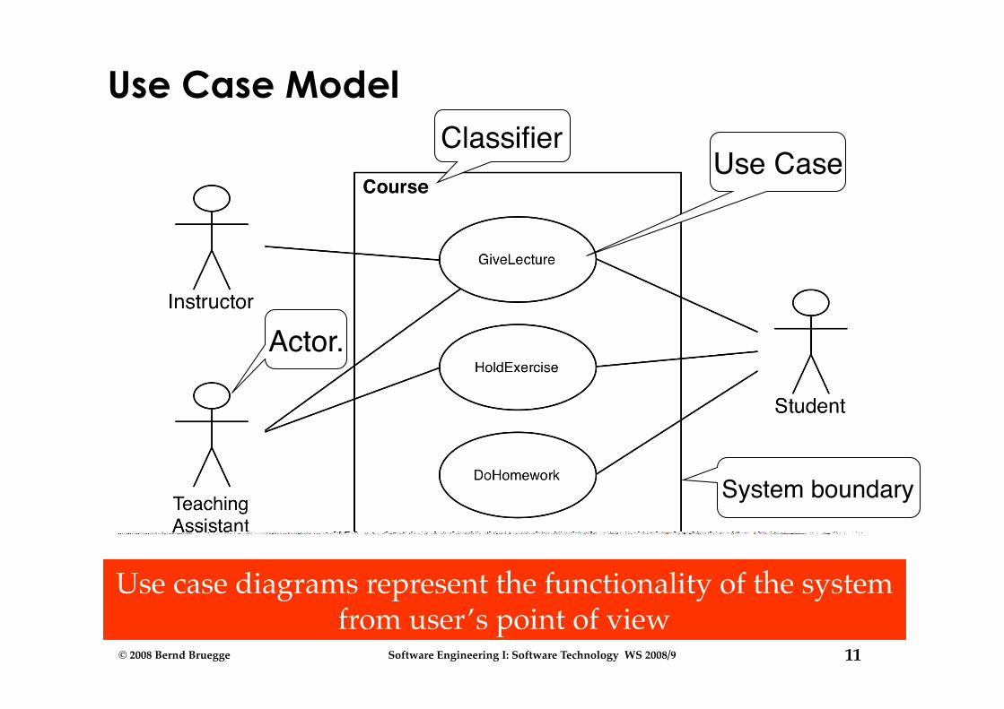
Use Case Model
Use case diagrams represent the functionality of the system from user’s point of view
Actor.
Use Case
System boundary
Classifier
12 © 2008 Bernd Bruegge Software Engineering I: Software Technology WS 2008/9
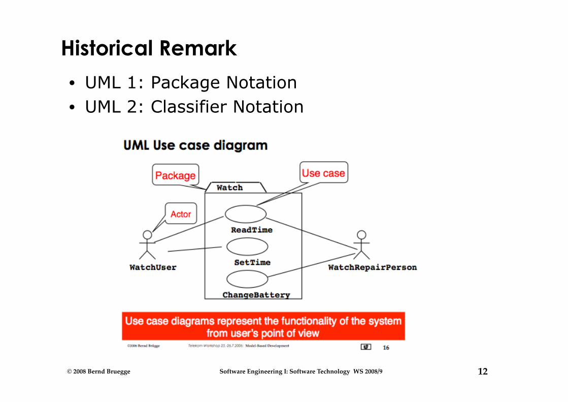
Historical Remark
• UML 1: Package Notation • UML 2: Classifier Notation

13 © 2008 Bernd Bruegge Software Engineering I: Software Technology WS 2008/9
Uses Cases can be related
• Extend Relationship • To represent seldom invoked use cases or exceptional
functionality
• Include Relationship • To represent functional behavior common to more than
one use case.
14 © 2008 Bernd Bruegge Software Engineering I: Software Technology WS 2008/9
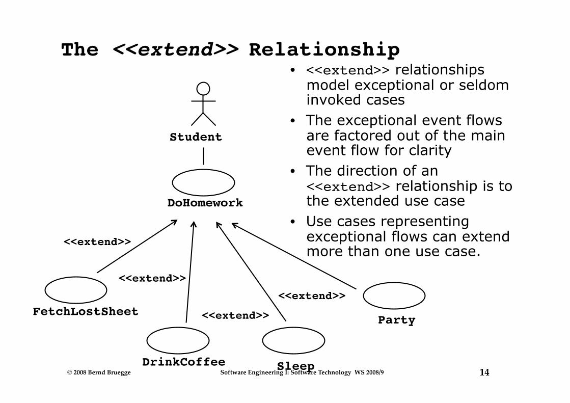
The <<extend>> Relationship • <<extend>> relationships
model exceptional or seldom invoked cases
• The exceptional event flows are factored out of the main event flow for clarity
• The direction of an <<extend>> relationship is to the extended use case
• Use cases representing exceptional flows can extend more than one use case.
Student
DoHomework
Party
<<extend>>
Sleep
<<extend>> FetchLostSheet
<<extend>>
DrinkCoffee
<<extend>>
15 © 2008 Bernd Bruegge Software Engineering I: Software Technology WS 2008/9
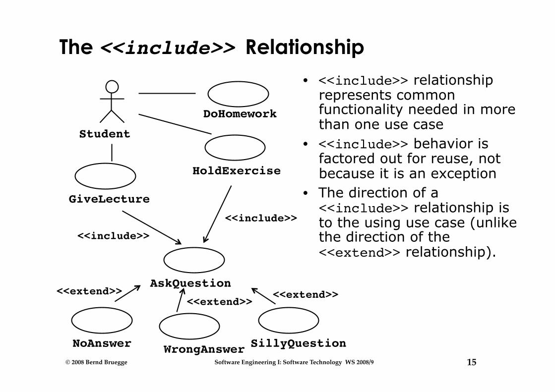
The <<include>> Relationship • <<include>> relationship
represents common functionality needed in more than one use case
• <<include>> behavior is factored out for reuse, not because it is an exception
• The direction of a <<include>> relationship is to the using use case (unlike the direction of the <<extend>> relationship).
Student
GiveLecture
HoldExercise
<<include>>
AskQuestion
<<include>>
NoAnswer
<<extend>>
SillyQuestion
<<extend>>
WrongAnswer
<<extend>>
DoHomework
16 © 2008 Bernd Bruegge Software Engineering I: Software Technology WS 2008/9
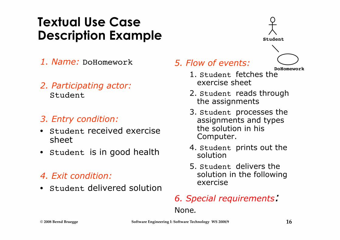
Textual Use Case Description Example
1. Name: DoHomework
2. Participating actor: Student
3. Entry condition: • Student received exercise
sheet • Student is in good health
4. Exit condition: • Student delivered solution
5. Flow of events: 1. Student fetches the
exercise sheet 2. Student reads through
the assignments 3. Student processes the
assignments and types the solution in his Computer.
4. Student prints out the solution
5. Student delivers the solution in the following exercise
6. Special requirements: None.
Student
DoHomework
17 © 2008 Bernd Bruegge Software Engineering I: Software Technology WS 2008/9
Where are we now?
What is UML and why do we use it? Functional model
Use case diagram
Object model Class diagram
• Dynamic model • Sequence diagram • State chart diagram • Activity diagram
18 © 2008 Bernd Bruegge Software Engineering I: Software Technology WS 2008/9
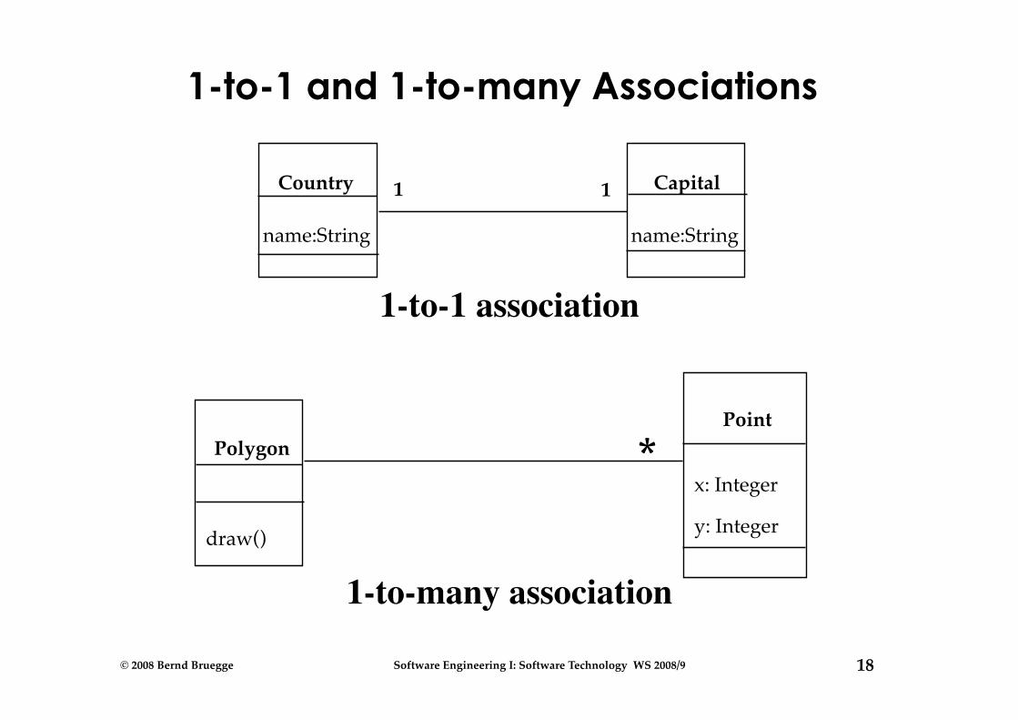
1-to-1 and 1-to-many Associations
1-to-1 association
1-to-many association
Polygon
draw()
Point
x: Integer
y: Integer
*
Country
name:String
Capital
name:String
1 1
19 © 2008 Bernd Bruegge Software Engineering I: Software Technology WS 2008/9
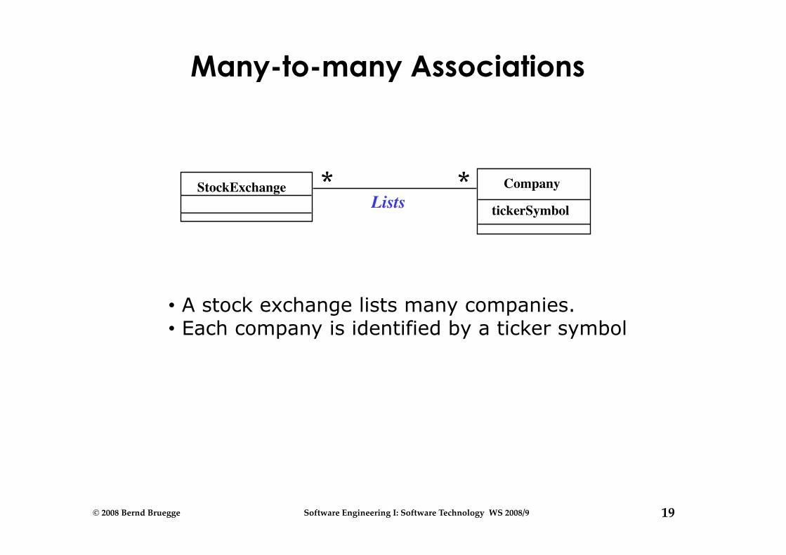
Many-to-many Associations
StockExchange Company
tickerSymbol Lists * *
• A stock exchange lists many companies. • Each company is identified by a ticker symbol
20 © 2008 Bernd Bruegge Software Engineering I: Software Technology WS 2008/9
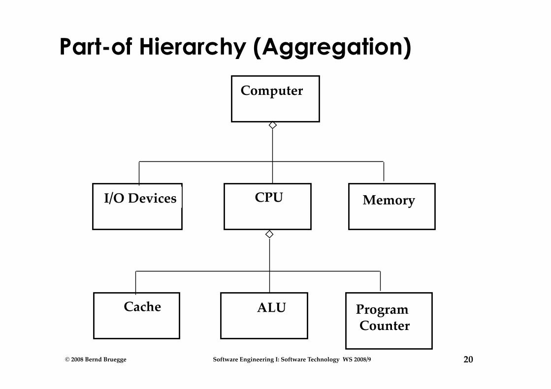
I/O Devices CPU Memory
Part-of Hierarchy (Aggregation)
Computer
Cache ALU Program Counter

21 © 2008 Bernd Bruegge Software Engineering I: Software Technology WS 2008/9
Aggregation • An aggregation is a special case of association denoting
a “consists-of” hierarchy • The aggregate is the parent class,
the components are the children classes
Exhaust system
Muffler diameter
Tailpipe diameter
1 0..2
TicketMachine
ZoneButton 3
A solid diamond denotes composition: A strong form of aggregation where the life time of the component instances is controlled by the aggregate (“the whole controls/destroys the parts”)
22 © 2008 Bernd Bruegge Software Engineering I: Software Technology WS 2008/9
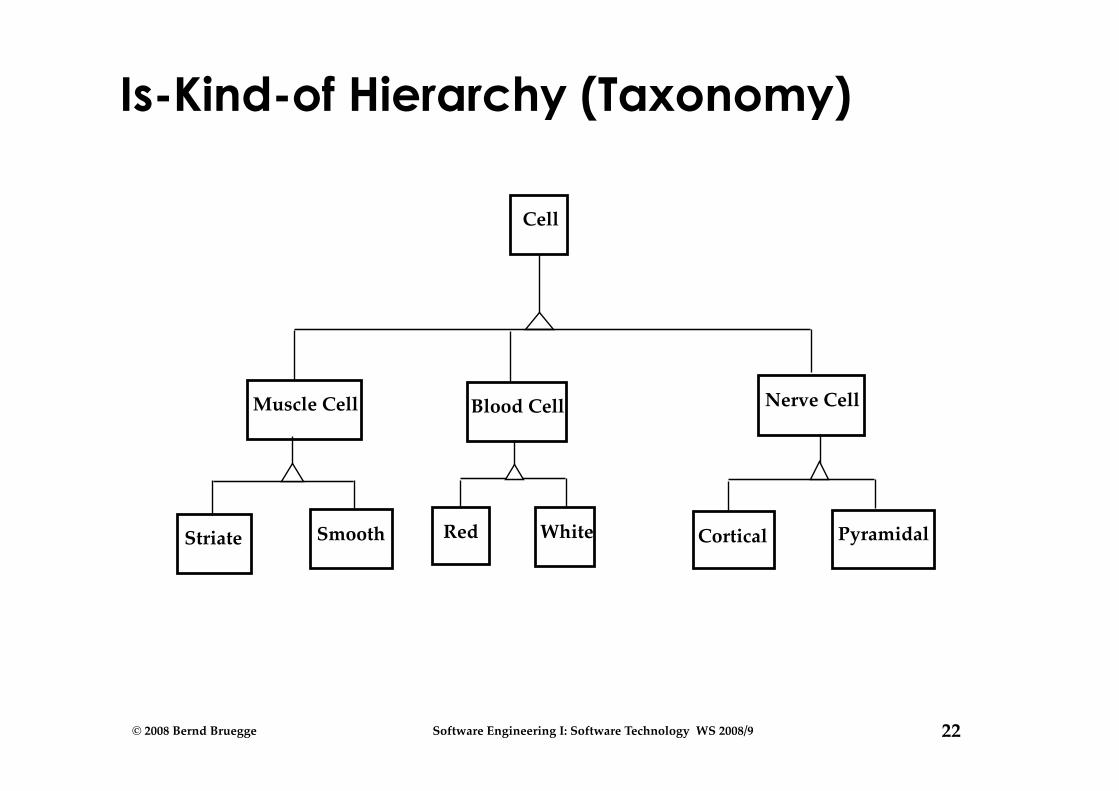
Is-Kind-of Hierarchy (Taxonomy)
Cell
Muscle Cell Blood Cell Nerve Cell
Striate Smooth Red White Cortical Pyramidal
23 © 2008 Bernd Bruegge Software Engineering I: Software Technology WS 2008/9
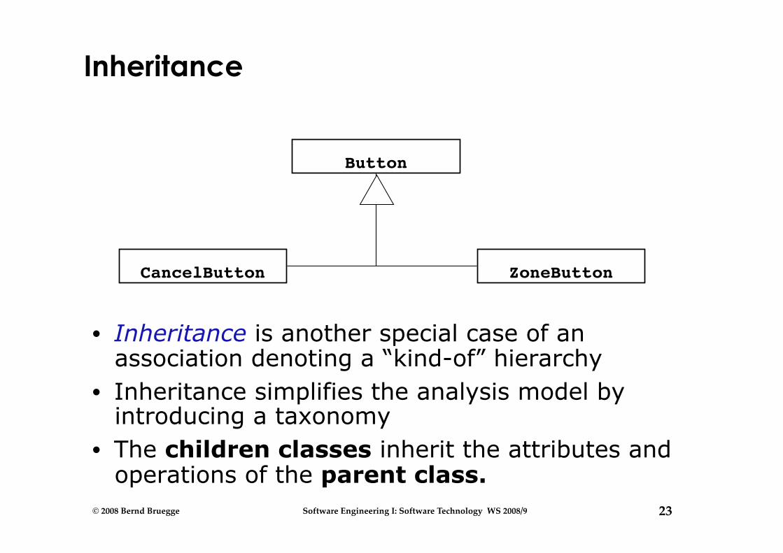
Inheritance
• Inheritance is another special case of an association denoting a “kind-of” hierarchy
• Inheritance simplifies the analysis model by introducing a taxonomy
• The children classes inherit the attributes and operations of the parent class.
Button
ZoneButton CancelButton
24 © 2008 Bernd Bruegge Software Engineering I: Software Technology WS 2008/9
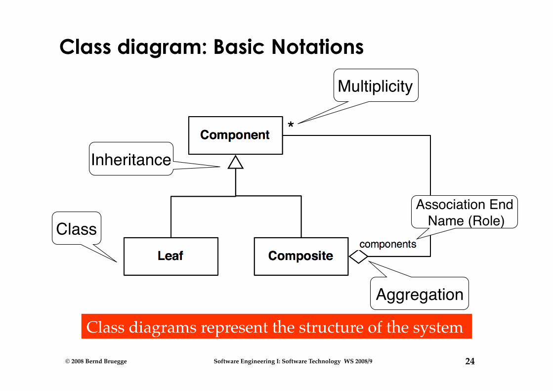
Class diagram: Basic Notations
Class Association End
Name (Role)
Multiplicity
Class diagrams represent the structure of the system
Aggregation
Inheritance
25 © 2008 Bernd Bruegge Software Engineering I: Software Technology WS 2008/9
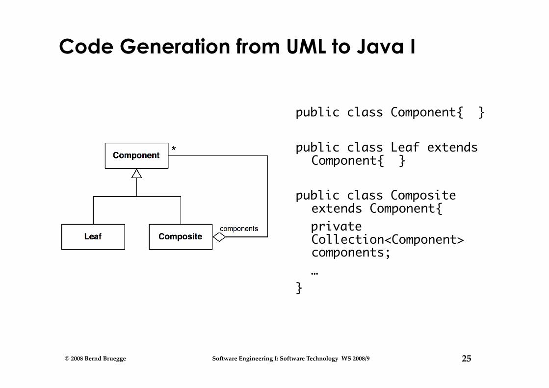
Code Generation from UML to Java I
public class Component{ }
public class Leaf extends Component{ }
public class Composite extends Component{
private Collection<Component> components;
… }

26 © 2008 Bernd Bruegge Software Engineering I: Software Technology WS 2008/9
Class diagram: Basic Notations
Association
Operation
Comment
Attribute
27 © 2008 Bernd Bruegge Software Engineering I: Software Technology WS 2008/9
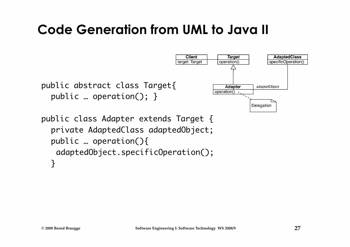
Code Generation from UML to Java II
public abstract class Target{public … operation(); }
public class Adapter extends Target {private AdaptedClass adaptedObject;public … operation(){adaptedObject.specificOperation();}
28 © 2008 Bernd Bruegge Software Engineering I: Software Technology WS 2008/9
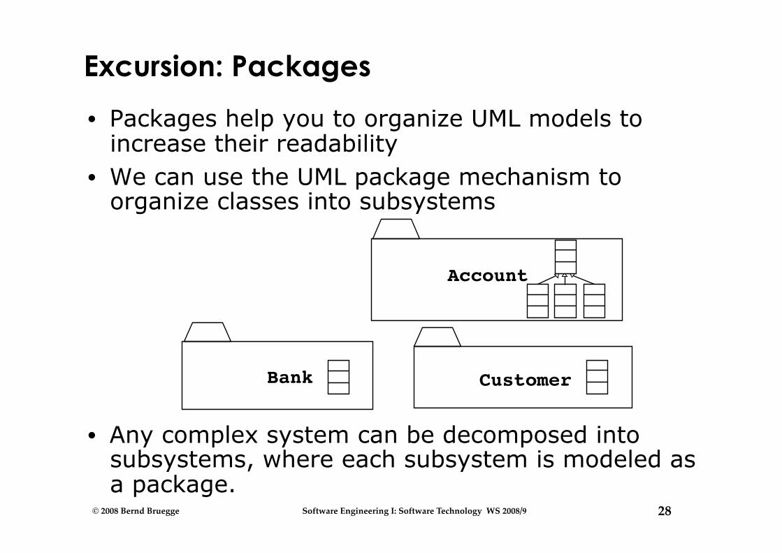
Excursion: Packages
• Packages help you to organize UML models to increase their readability
• We can use the UML package mechanism to organize classes into subsystems
• Any complex system can be decomposed into subsystems, where each subsystem is modeled as a package.
Account
Customer Bank

29 © 2008 Bernd Bruegge Software Engineering I: Software Technology WS 2008/9
Where are we now?
What is UML? Functional model
Use case diagram
Object model Class diagram
Dynamic model Sequence diagram • State chart diagram • Activity diagram
30 © 2008 Bernd Bruegge Software Engineering I: Software Technology WS 2008/9
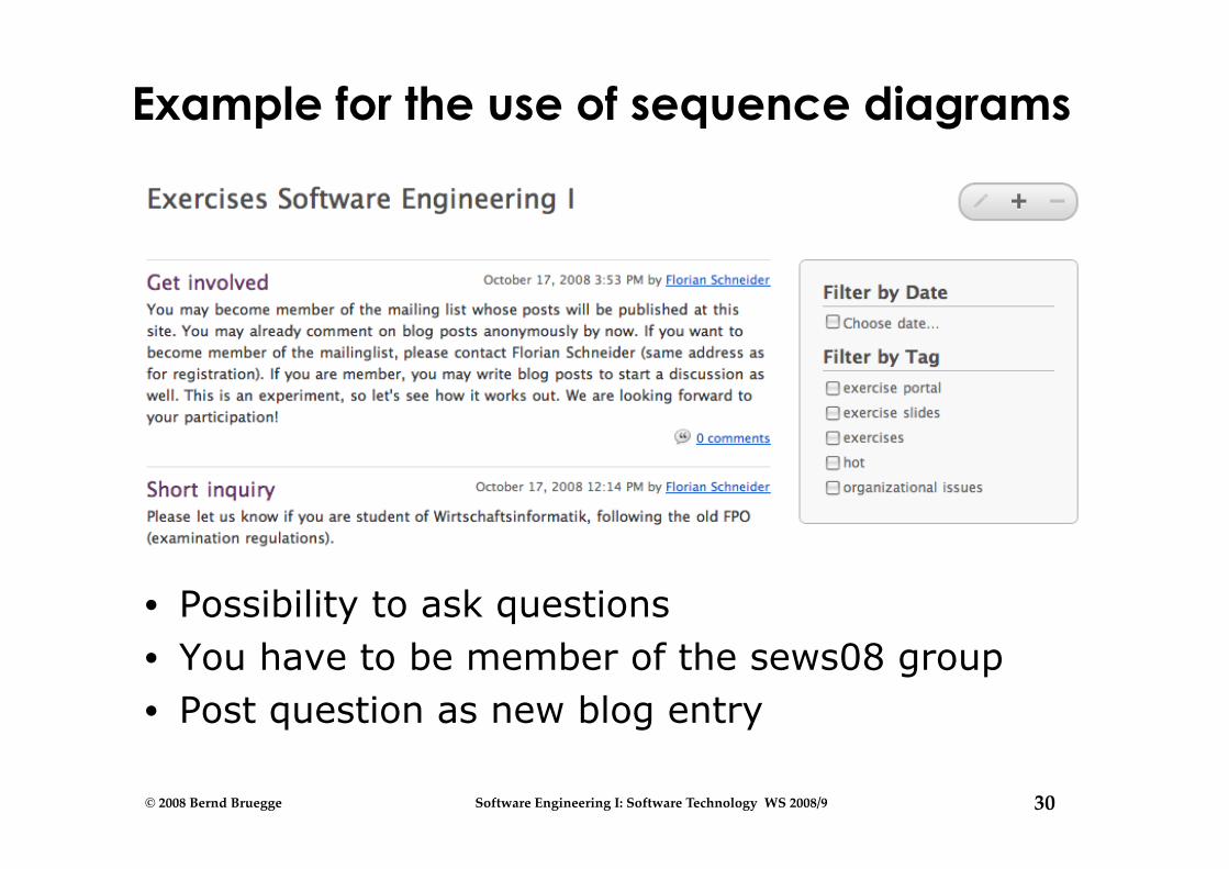
Example for the use of sequence diagrams
• Possibility to ask questions • You have to be member of the sews08 group • Post question as new blog entry
31 © 2008 Bernd Bruegge Software Engineering I: Software Technology WS 2008/9
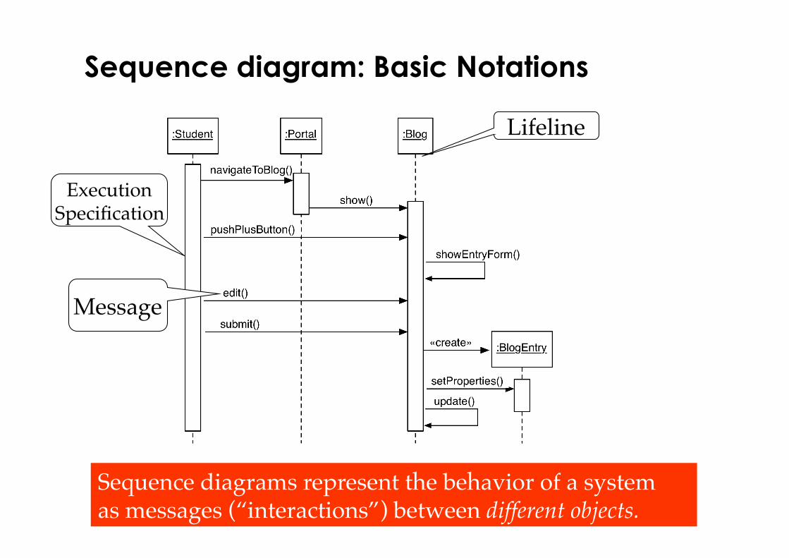
Execution�Specification
Sequence diagram: Basic Notations
Sequence diagrams represent the behavior of a system as messages (“interactions”) between different objects.
Lifeline
Message

32 © 2008 Bernd Bruegge Software Engineering I: Software Technology WS 2008/9
Lifeline and Execution Specification
• A lifeline represents an individual participant (or object) in the interaction
• A lifeline is shown using a symbol that consists of a rectangle forming its “head” followed by a vertical line (which may be dashed) that represents the lifetime of the participant
• An execution specification specifies a behavior or interaction within the lifeline
• An execution specification is represented as a thin rectangle on the lifeline.
33 © 2008 Bernd Bruegge Software Engineering I: Software Technology WS 2008/9
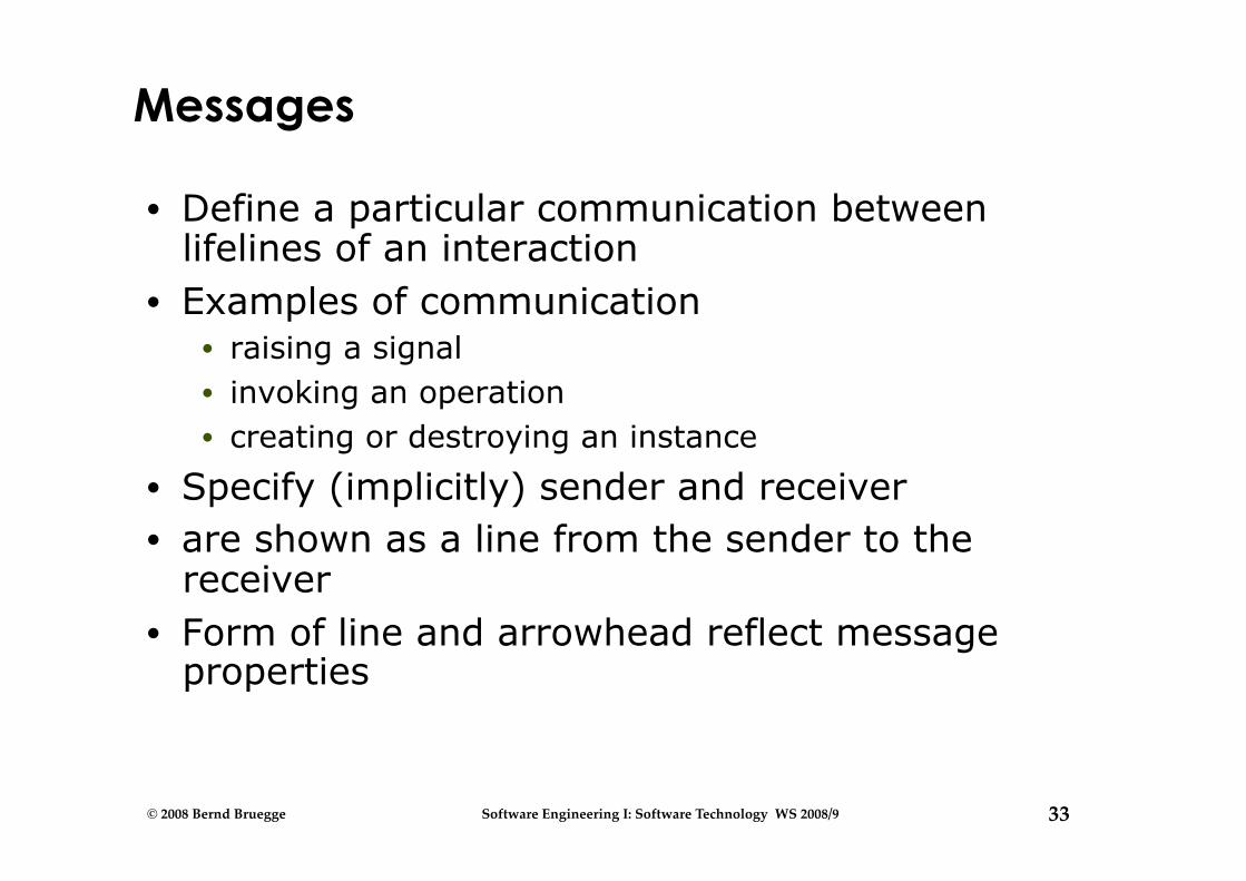
Messages
• Define a particular communication between lifelines of an interaction
• Examples of communication • raising a signal • invoking an operation • creating or destroying an instance
• Specify (implicitly) sender and receiver • are shown as a line from the sender to the
receiver • Form of line and arrowhead reflect message
properties
34 © 2008 Bernd Bruegge Software Engineering I: Software Technology WS 2008/9
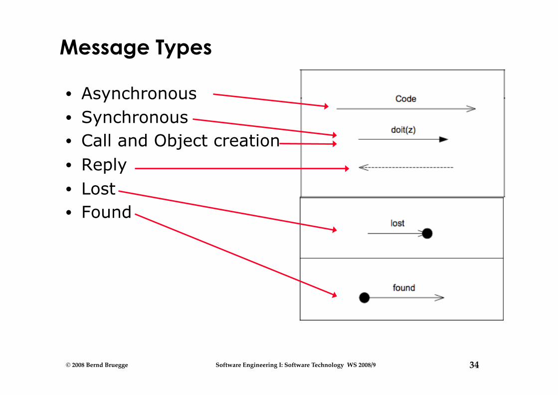
Message Types
• Asynchronous • Synchronous • Call and Object creation • Reply • Lost • Found
35 © 2008 Bernd Bruegge Software Engineering I: Software Technology WS 2008/9
Where are we now?
What is UML? Functional model
Use case diagram
Object model Class diagram
Dynamic model Sequence diagram State chart diagram Activity diagram
36 © 2008 Bernd Bruegge Software Engineering I: Software Technology WS 2008/9
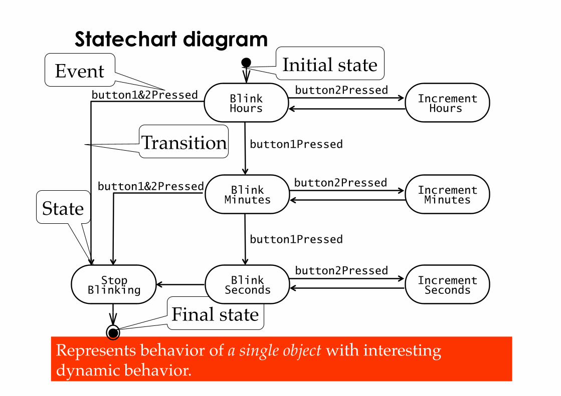
Statechart diagram
State
Initial state
Final state
Transition
Event
Represents behavior of a single object with interesting dynamic behavior.
button1&2Pressed
button1Pressed
button2Pressed
button2Pressed
button2Pressed
button1Pressed
button1&2Pressed Increment Minutes
Increment Hours
Blink Hours
Blink Seconds
Blink Minutes
Increment Seconds
Stop Blinking
37 © 2008 Bernd Bruegge Software Engineering I: Software Technology WS 2008/9
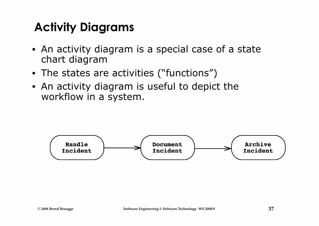
Activity Diagrams
• An activity diagram is a special case of a state chart diagram
• The states are activities (“functions”) • An activity diagram is useful to depict the
workflow in a system.
38 © 2008 Bernd Bruegge Software Engineering I: Software Technology WS 2008/9
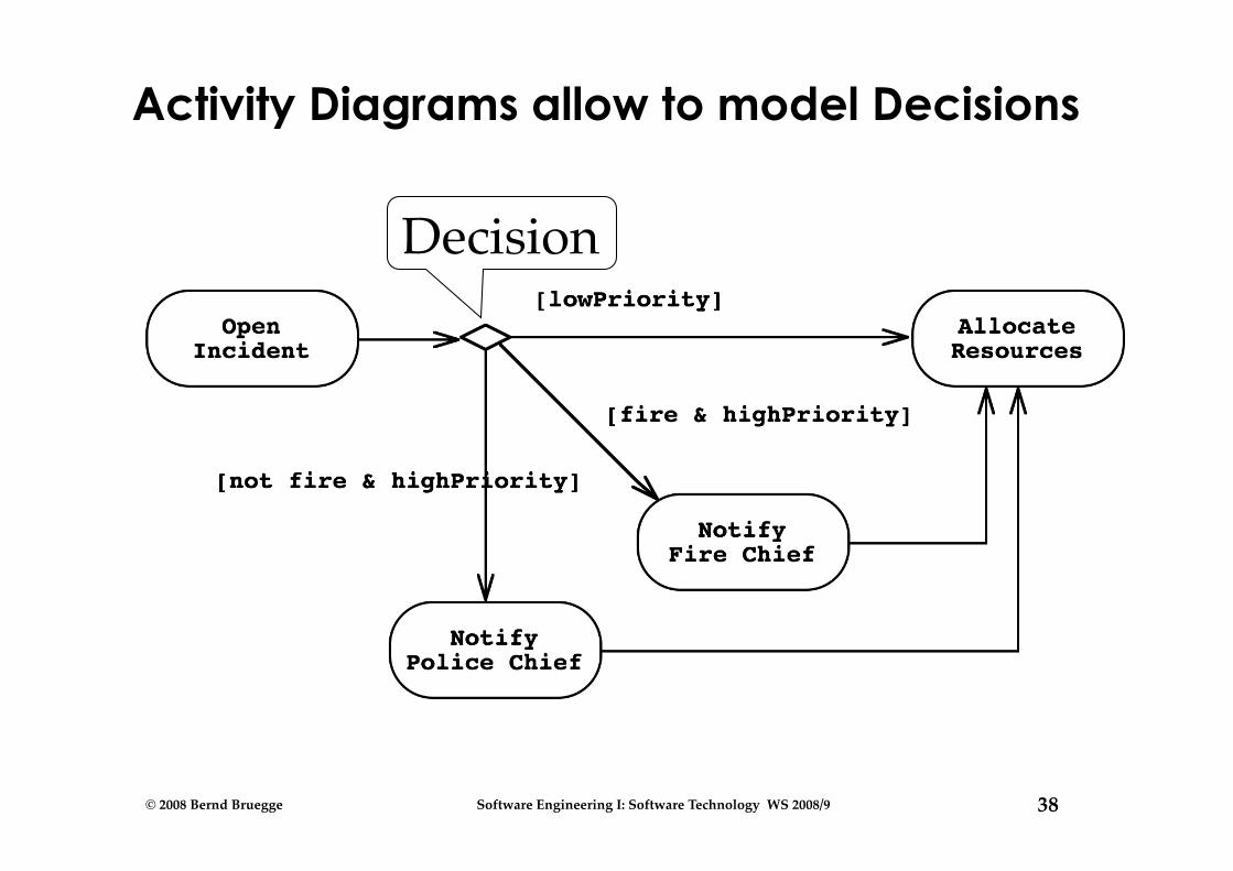
Activity Diagrams allow to model Decisions
Decision
39 © 2008 Bernd Bruegge Software Engineering I: Software Technology WS 2008/9
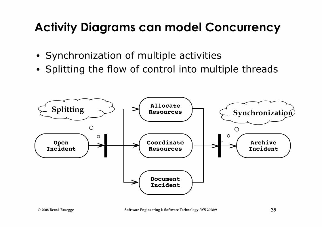
Activity Diagrams can model Concurrency
• Synchronization of multiple activities • Splitting the flow of control into multiple threads
Synchronization Splitting
40 © 2008 Bernd Bruegge Software Engineering I: Software Technology WS 2008/9
Backup Slides
41 © 2008 Bernd Bruegge Software Engineering I: Software Technology WS 2008/9
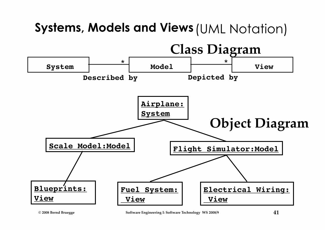
Systems, Models and Views
System View * Model *
Depicted by Described by
Airplane:System
Scale Model:Model Flight Simulator:Model
Fuel System: View
Electrical Wiring: View
Blueprints: View
(UML Notation)
Class Diagram
Object Diagram

42 © 2008 Bernd Bruegge Software Engineering I: Software Technology WS 2008/9
Reality: A stock exchange lists many companies. Each company is identified by a ticker symbol Analysis results in analysis object model (UML Class diagram):
StockExchange Company
tickerSymbol Lists * *
Implementation results in source code (Java): public class StockExchange { public m_Company = new Vector(); }; public class Company { public int m_tickerSymbol; public Vector m_StockExchange = new Vector(); };
Model-driven Software Development
43 © 2008 Bernd Bruegge Software Engineering I: Software Technology WS 2008/9
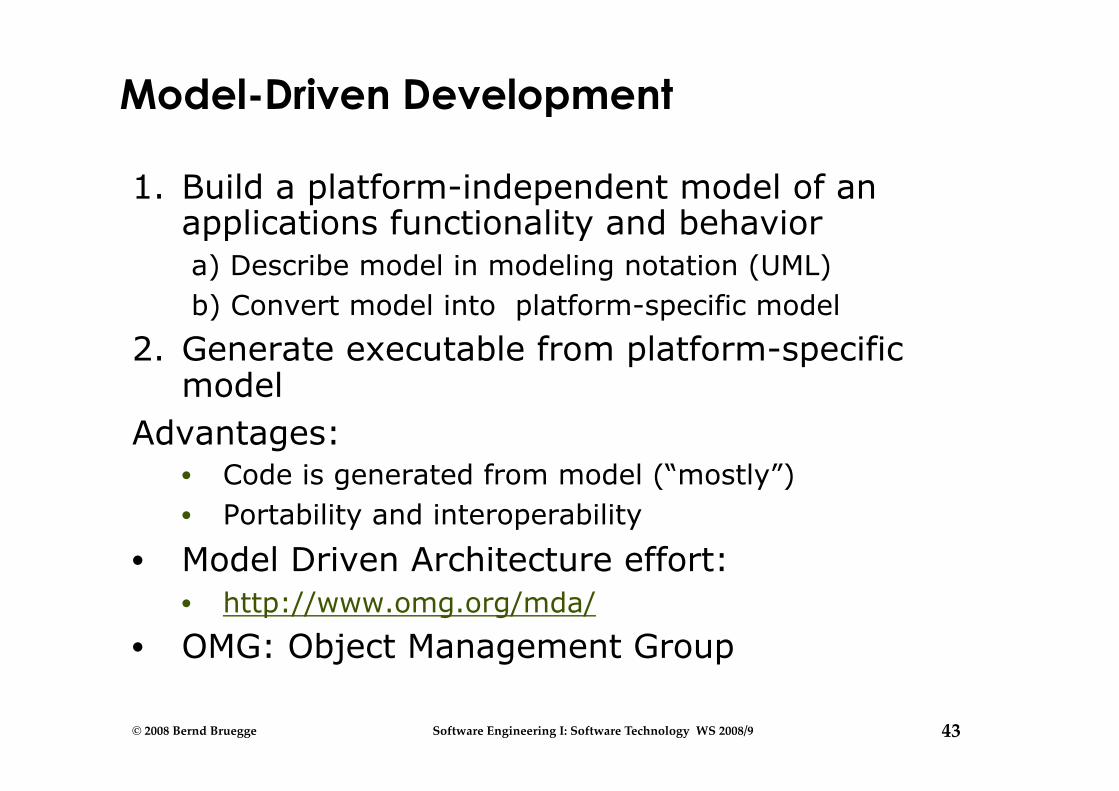
Model-Driven Development
1. Build a platform-independent model of an applications functionality and behavior a) Describe model in modeling notation (UML) b) Convert model into platform-specific model
2. Generate executable from platform-specific model
Advantages: • Code is generated from model (“mostly”) • Portability and interoperability
• Model Driven Architecture effort: • http://www.omg.org/mda/
• OMG: Object Management Group
44 © 2008 Bernd Bruegge Software Engineering I: Software Technology WS 2008/9
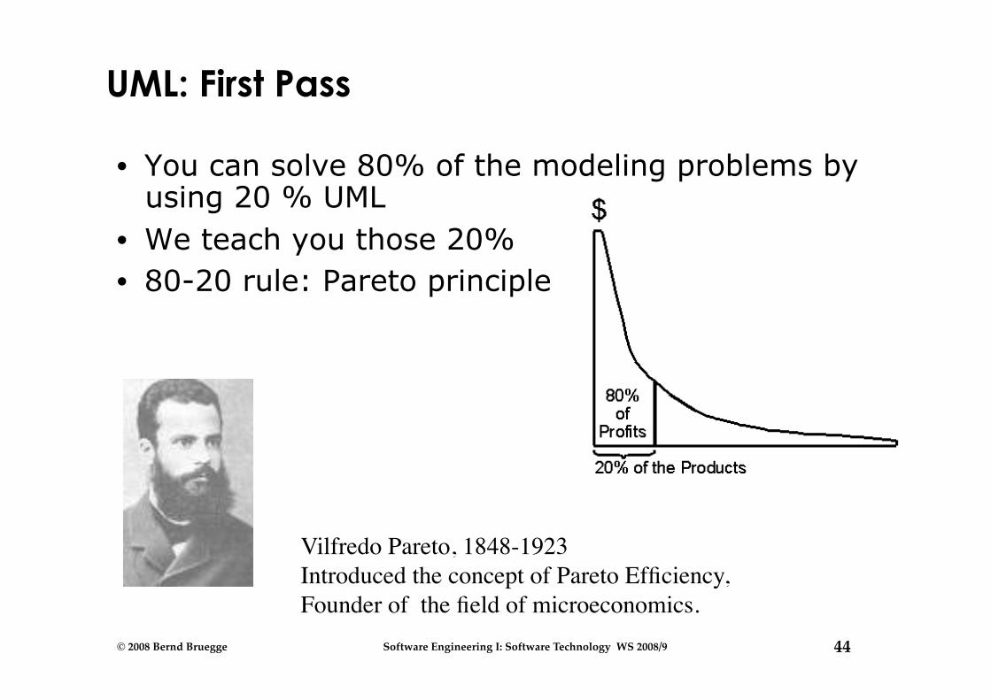
UML: First Pass
• You can solve 80% of the modeling problems by using 20 % UML
• We teach you those 20% • 80-20 rule: Pareto principle
Vilfredo Pareto, 1848-1923 Introduced the concept of Pareto Efficiency, Founder of the field of microeconomics.