Embed Size (px)
Citation preview

Usin
g U
ML,
Pat
tern
s, an
d Ja
vaO
bjec
t-Ori
ente
d So
ftwar
e En
gine
erin
g Chapter 2, Modeling with UML, Part 2
Bernd Bruegge & Allen H. Dutoit Object-Oriented Software Engineering: Using UML, Patterns, and Java 2
Outline of this Class
• What is UML? • A more detailed view on
ü Use case diagrams ü Class diagrams ü Sequence diagrams ü Activity/Statecharts diagrams

Bernd Bruegge & Allen H. Dutoit Object-Oriented Software Engineering: Using UML, Patterns, and Java 3
UML Basic Notation: First Summary
• UML provides a wide variety of notations for modeling many aspects of software systems
• UML diagrams cover the three fundamental models for software design:
• Functional model: Use case diagrams • Object model: Class diagrams • Dynamic model: Sequence diagrams, statechart diagram
• Now we go into a little bit more detail…

Bernd Bruegge & Allen H. Dutoit Object-Oriented Software Engineering: Using UML, Patterns, and Java 4
UML First Pass
• Use case diagrams • Describe the functional behavior of the system as seen
by the user
• Class diagrams • Describe the static structure of the system: Objects,
attributes, associations
• Sequence diagrams • Describe the dynamic behavior between objects of the
system
• Statechart diagrams • Describe the dynamic behavior of an individual object
• Activity diagrams • Describe the dynamic behavior of a system, in
particular the workflow.

Bernd Bruegge & Allen H. Dutoit Object-Oriented Software Engineering: Using UML, Patterns, and Java 5
UML Use Case Diagram

Bernd Bruegge & Allen H. Dutoit Object-Oriented Software Engineering: Using UML, Patterns, and Java 6
UML first pass: Use case diagrams
Use case diagrams represent the functionality of the systemfrom user’s point of view
Actor.
Use Case
System boundary
Classifier

Bernd Bruegge & Allen H. Dutoit Object-Oriented Software Engineering: Using UML, Patterns, and Java 7
UML Use Case Diagrams
An Actor represents a role, that is, a type of user of the system
Passenger
PurchaseTicket
Used during requirements elicitation and analysis to represent external behavior (“visible from the outside of the system”)
Use case model: The set of all use cases that completely describe the functionality of the system.
A use case represents a class of functionality provided by the system
Bernd Bruegge & Allen H. Dutoit Object-Oriented Software Engineering: Using UML, Patterns, and Java 8
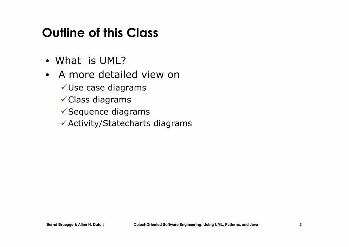
Actors
• An actor is a model for an external entity which interacts (communicates) with the system:
• User • External system (Another system) • Physical environment (e.g. Weather)
• An actor has a unique name and an optional description
• Examples: • Passenger: A person in the train • GPS satellite: An external system that
provides the system with GPS coordinates.
Passenger
Name
Optional Description

Bernd Bruegge & Allen H. Dutoit Object-Oriented Software Engineering: Using UML, Patterns, and Java 9
Use Case • A use case represents a class of
functionality provided by the system
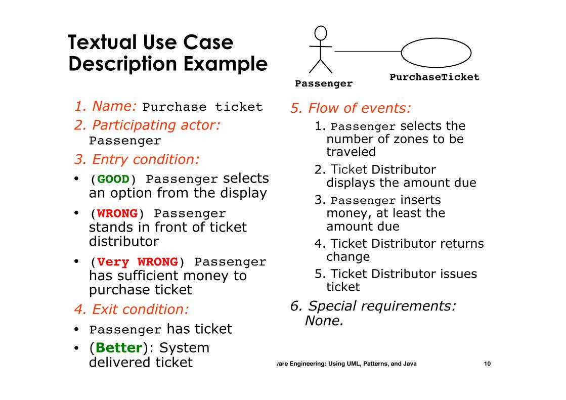
• Use cases can be described textually, with a focus on the event flow between actor and system
• The textual use case description consists of 6 parts: 1. Unique name 2. Participating actors 3. Entry conditions 4. Exit conditions 5. Flow of events 6. Special requirements.
PurchaseTicket
Bernd Bruegge & Allen H. Dutoit Object-Oriented Software Engineering: Using UML, Patterns, and Java 10
Textual Use Case Description Example
1. Name: Purchase ticket 2. Participating actor: Passenger
3. Entry condition: • (GOOD) Passenger selects
an option from the display• (WRONG) Passenger
stands in front of ticket distributor
• (Very WRONG) Passenger has sufficient money to purchase ticket
4. Exit condition: • Passenger has ticket • (Better): System
delivered ticket
5. Flow of events: 1. Passenger selects the
number of zones to be traveled
2. Ticket Distributor displays the amount due
3. Passenger inserts money, at least the amount due
4. Ticket Distributor returns change
5. Ticket Distributor issues ticket
6. Special requirements: None.
PassengerPurchaseTicket

Bernd Bruegge & Allen H. Dutoit Object-Oriented Software Engineering: Using UML, Patterns, and Java 11
Use Cases can be related
• Extends Relationship • To represent seldom invoked use cases or exceptional
functionality
• Includes Relationship • To represent functional behavior common to more than
one use case.
Bernd Bruegge & Allen H. Dutoit Object-Oriented Software Engineering: Using UML, Patterns, and Java 12
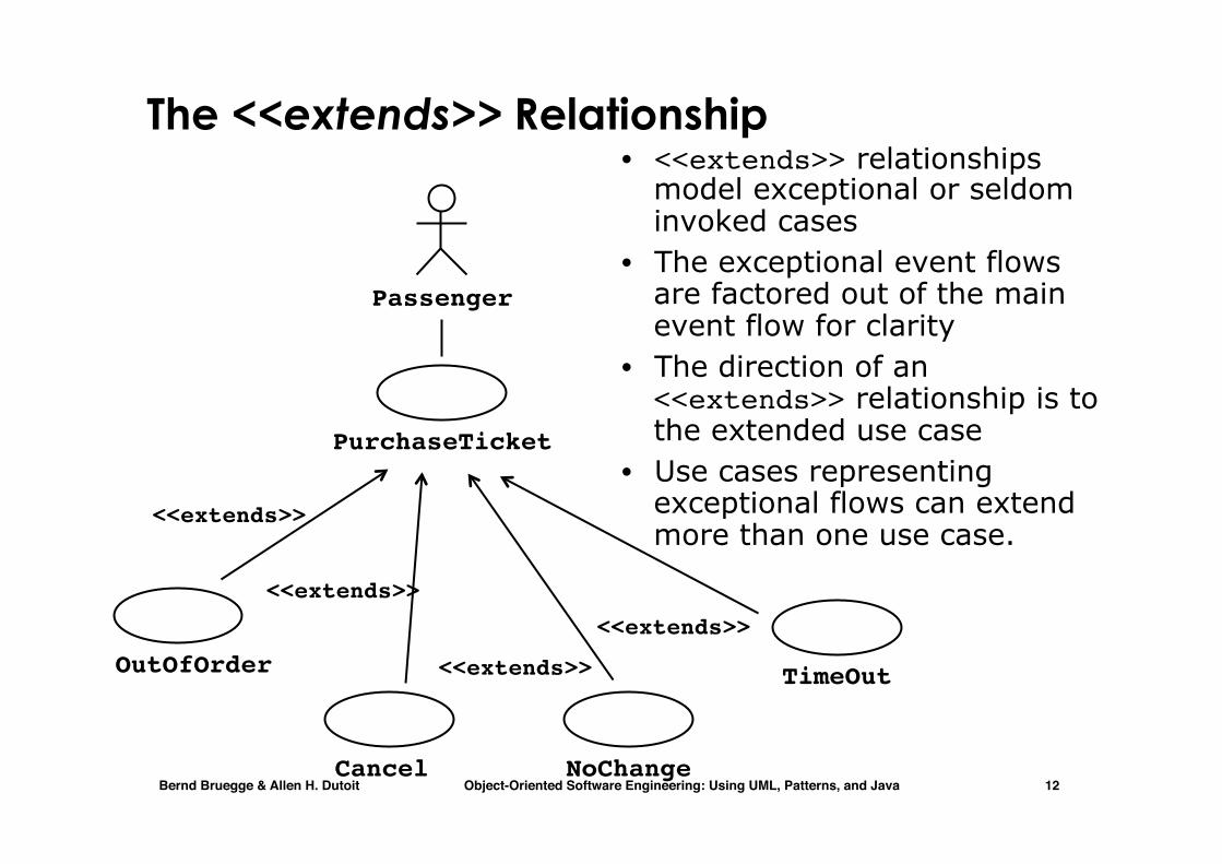
The <<extends>> Relationship • <<extends>> relationships
model exceptional or seldom invoked cases
• The exceptional event flows are factored out of the main event flow for clarity
• The direction of an <<extends>> relationship is to the extended use case
• Use cases representing exceptional flows can extend more than one use case.
Passenger
PurchaseTicket
TimeOut
<<extends>>
NoChange
<<extends>>OutOfOrder
<<extends>>
Cancel
<<extends>>

Bernd Bruegge & Allen H. Dutoit Object-Oriented Software Engineering: Using UML, Patterns, and Java 13
The <<includes>> Relationship • <<includes>> relationship
represents common functionality needed in more than one use case
• <<includes>> behavior is factored out for reuse, not because it is an exception
• The direction of a <<includes>> relationship is to the using use case (unlike the direction of the <<extends>> relationship).
Passenger
PurchaseSingleTicket
PurchaseMultiCard
<<includes>>
CollectMoney
<<includes>>
NoChange
<<extends>>
TimeOut
<<extends>>
Cancel
<<extends>>

Bernd Bruegge & Allen H. Dutoit Object-Oriented Software Engineering: Using UML, Patterns, and Java 14
Use Case Models can be packaged
Actor.
Use Case
System boundary
Classifier

Bernd Bruegge & Allen H. Dutoit Object-Oriented Software Engineering: Using UML, Patterns, and Java 15
Historical Remark: UML 1 used packages
Instructor
Package Course
GiveLecture
HoldExercise
DoHomework
Student
Teaching Assistent

Bernd Bruegge & Allen H. Dutoit Object-Oriented Software Engineering: Using UML, Patterns, and Java 16
UML Class Diagram

Bernd Bruegge & Allen H. Dutoit Object-Oriented Software Engineering: Using UML, Patterns, and Java 17
UML first pass: Class diagrams
ClassAssociation
Multiplicity
Class diagrams represent the structure of the system
2 1 1
1 1
1 1
2
SimpleWatch
Display Battery Time PushButton

Bernd Bruegge & Allen H. Dutoit Object-Oriented Software Engineering: Using UML, Patterns, and Java 18
UML first pass: Class diagrams
12
push() release()
1
1
blinkIdxblinkSeconds()blinkMinutes()blinkHours()stopBlinking()referesh()
LCDDisplay BatteryLoad
1
2
1
TimeNow
1
Watch
Operations
statePushButton
Attribute
Class diagrams represent the structure of the system
ClassAssociation
Multiplicity

Bernd Bruegge & Allen H. Dutoit Object-Oriented Software Engineering: Using UML, Patterns, and Java 19
Class Diagrams
• Class diagrams represent the structure of the system
• Used • during requirements analysis to model application
domain concepts • during system design to model subsystems • during object design to specify the detailed behavior
and attributes of classes.
Table zone2priceEnumeration getZones()Price getPrice(Zone)
TarifSchedule
* *
Tripzone:Zone
Price: Price

Bernd Bruegge & Allen H. Dutoit Object-Oriented Software Engineering: Using UML, Patterns, and Java 20
Classes
• A class represents a concept • A class encapsulates state (attributes) and behavior
(operations)
Table zone2priceEnumeration getZones()Price getPrice(Zone)
TarifSchedule
zone2pricegetZones()getPrice()
TarifSchedule
Name
Attributes
Operations
Signature
TarifSchedule
The class name is the only mandatory information
Each attribute has a type Each operation has a signature
Type

Bernd Bruegge & Allen H. Dutoit Object-Oriented Software Engineering: Using UML, Patterns, and Java 21
Actor vs Class vs Object
• Actor • An entity outside the system to be modeled,
interacting with the system (“Passenger”) • Class
• An abstraction modeling an entity in the application or solution domain
• The class is part of the system model (“User”, “Ticket distributor”, “Server”)
• Object • A specific instance of a class (“Joe, the passenger who
is purchasing a ticket from the ticket distributor”).

Bernd Bruegge & Allen H. Dutoit Object-Oriented Software Engineering: Using UML, Patterns, and Java 22
Instances
• An instance represents a phenomenon • The attributes are represented with their values • The name of an instance is underlined • The name can contain only the class name of the instance
(anonymous instance)
zone2price = {{‘1’, 0.20}, {‘2’, 0.40},{‘3’, 0.60}}
tarif2006:TarifSchedulezone2price = {{‘1’, 0.20}, {‘2’, 0.40},{‘3’, 0.60}}
:TarifSchedule

Bernd Bruegge & Allen H. Dutoit Object-Oriented Software Engineering: Using UML, Patterns, and Java 23
Associations
Associations denote relationships between classes
Price Zone
Enumeration getZones()Price getPrice(Zone)
TarifSchedule TripLeg
* *
The multiplicity of an association end denotes how many objects the instance of a class can legitimately reference.

Bernd Bruegge & Allen H. Dutoit Object-Oriented Software Engineering: Using UML, Patterns, and Java 24
1-to-1 and 1-to-many Associations
1-to-1 association
1-to-many association
Polygon
draw()
Point
x: Integer
y: Integer
*
Country
name:String
City
name:String
11

Bernd Bruegge & Allen H. Dutoit Object-Oriented Software Engineering: Using UML, Patterns, and Java 25
Many-to-many Associations
StockExchange Company
tickerSymbolLists **
• A stock exchange lists many companies. • Each company is identified by a ticker symbol

Bernd Bruegge & Allen H. Dutoit Object-Oriented Software Engineering: Using UML, Patterns, and Java 26
From Problem Statement To Object Model
Class Diagram:
StockExchange Company
tickerSymbolLists
**
Problem Statement: A stock exchange lists many companies. Each company is uniquely identified by a ticker symbol
Bernd Bruegge & Allen H. Dutoit Object-Oriented Software Engineering: Using UML, Patterns, and Java 27
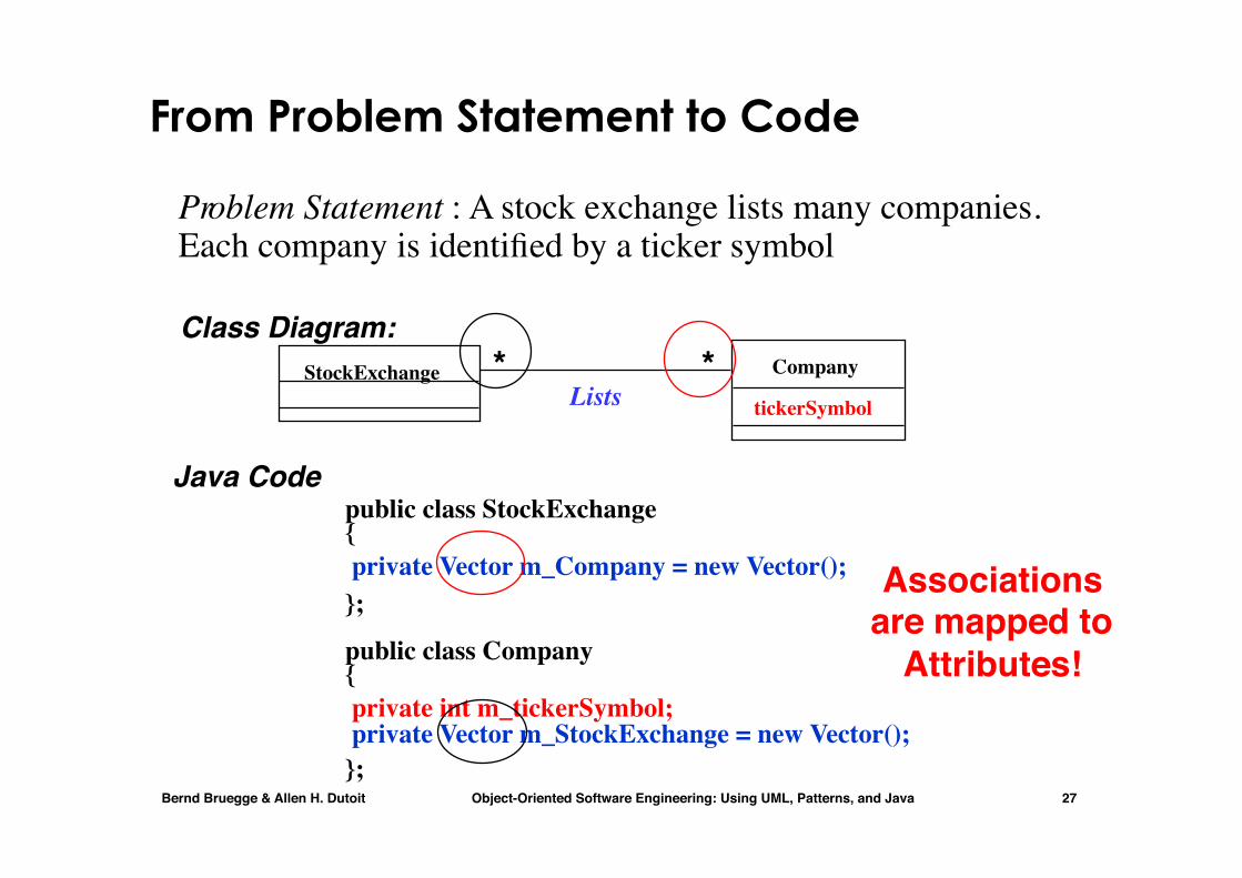
From Problem Statement to Code
Problem Statement : A stock exchange lists many companies. Each company is identified by a ticker symbol
Class Diagram:
private Vector m_Company = new Vector();
private int m_tickerSymbol; private Vector m_StockExchange = new Vector();
public class StockExchange{
};
public class Company{
};
Java Code
StockExchange Company
tickerSymbolLists **
Associationsare mapped to
Attributes!

Bernd Bruegge & Allen H. Dutoit Object-Oriented Software Engineering: Using UML, Patterns, and Java 28
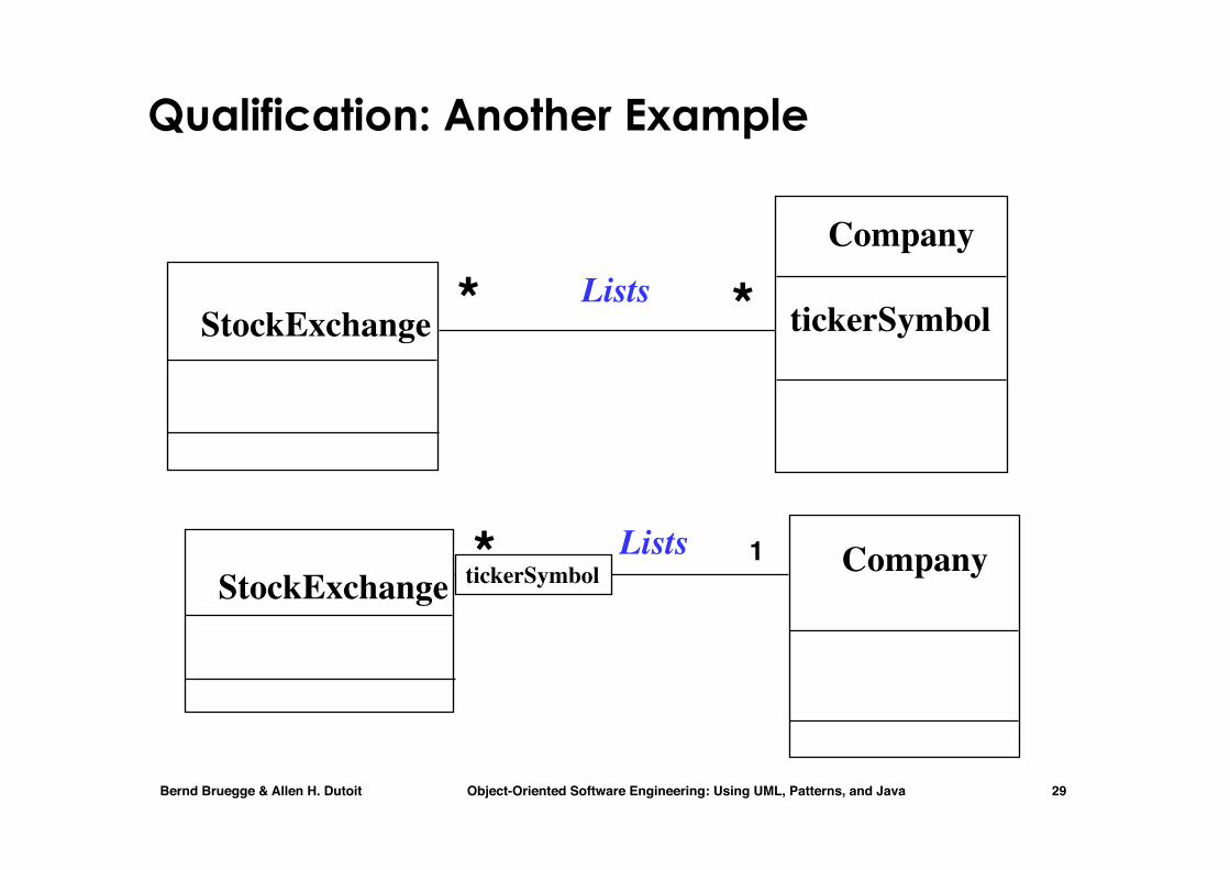
Qualifiers
• Qualifiers can be used to reduce the multiplicity of an association
DirectoryFile
filename
Without qualification1 *
With qualification0..1
Directory File1
filename
Bernd Bruegge & Allen H. Dutoit Object-Oriented Software Engineering: Using UML, Patterns, and Java 29
Qualification: Another Example
*StockExchangeCompanyLists *tickerSymbol
1
StockExchange
Company
tickerSymbolLists **

Bernd Bruegge & Allen H. Dutoit Object-Oriented Software Engineering: Using UML, Patterns, and Java 30
Aggregation • An aggregation is a special case of association denoting
a “consists-of” hierarchy • The aggregate is the parent class,
the components are the children classes
Exhaust system
Mufflerdiameter
Tailpipediameter
1 0..2
TicketMachine
ZoneButton3
A solid diamond denotes composition: A strong form of aggregation where the life time of the component instances is controlled by the aggregate. That is, the parts don’t exist on their won (“the whole controls/destroys the parts”)
Bernd Bruegge & Allen H. Dutoit Object-Oriented Software Engineering: Using UML, Patterns, and Java 31
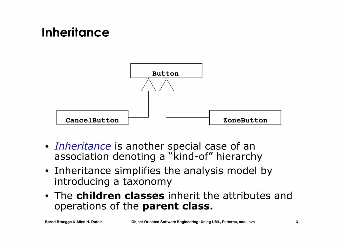
Inheritance
• Inheritance is another special case of an association denoting a “kind-of” hierarchy
• Inheritance simplifies the analysis model by introducing a taxonomy
• The children classes inherit the attributes and operations of the parent class.
Button
ZoneButtonCancelButton

Bernd Bruegge & Allen H. Dutoit Object-Oriented Software Engineering: Using UML, Patterns, and Java 32
Association class

Bernd Bruegge & Allen H. Dutoit Object-Oriented Software Engineering: Using UML, Patterns, and Java 33
Ternary associations
Bernd Bruegge & Allen H. Dutoit Object-Oriented Software Engineering: Using UML, Patterns, and Java 34
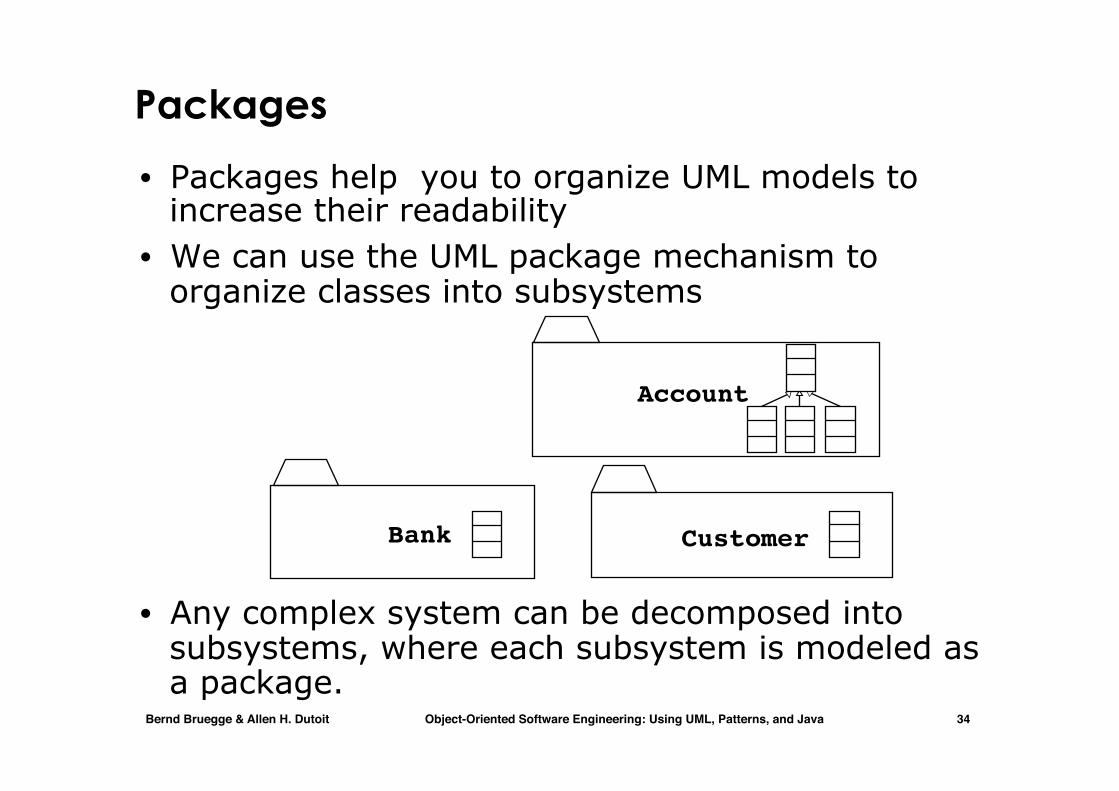
Packages
• Packages help you to organize UML models to increase their readability
• We can use the UML package mechanism to organize classes into subsystems
• Any complex system can be decomposed into subsystems, where each subsystem is modeled as a package.
Account
CustomerBank
Bernd Bruegge & Allen H. Dutoit Object-Oriented Software Engineering: Using UML, Patterns, and Java 35
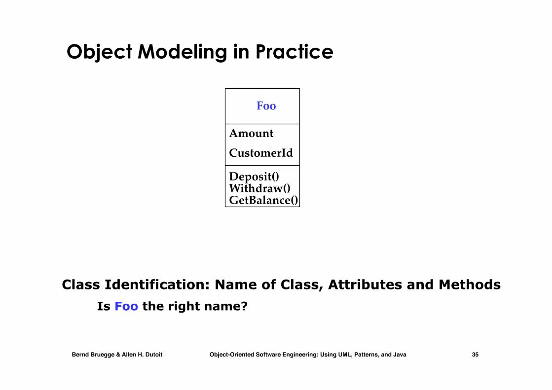
Object Modeling in Practice
Class Identification: Name of Class, Attributes and Methods Is Foo the right name?
Foo
AmountCustomerId
Deposit()Withdraw()GetBalance()
Bernd Bruegge & Allen H. Dutoit Object-Oriented Software Engineering: Using UML, Patterns, and Java 36
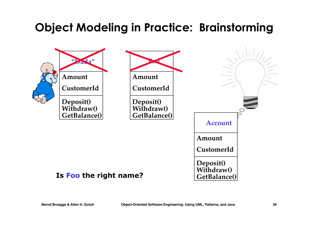
Object Modeling in Practice: Brainstorming
Foo
AmountCustomerId
Deposit()Withdraw()GetBalance()
Account
AmountCustomerId
Deposit()Withdraw()GetBalance()Is Foo the right name?
“Dada”
AmountCustomerId
Deposit()Withdraw()GetBalance()

Bernd Bruegge & Allen H. Dutoit Object-Oriented Software Engineering: Using UML, Patterns, and Java 37
Object Modeling in Practice: More classes
Account
Amount
Deposit()Withdraw()GetBalance()
Customer
NameCustomerId
CustomerIdAccountIdBank
Name
1) Find New Classes2) Review Names, Attributes and Methods

Bernd Bruegge & Allen H. Dutoit Object-Oriented Software Engineering: Using UML, Patterns, and Java 38
Object Modeling in Practice: Associations
Account
Amount
Deposit()Withdraw()GetBalance()
Customer
NameCustomerId
CustomerIdAccountIdAccountIdBank
Name
1) Find New Classes2) Review Names, Attributes and Methods
3) Find Associations between Classes
owns
4) Label the generic assocations
6) Review associations
*2
*?has
5) Determine the multiplicity of the assocations

Bernd Bruegge & Allen H. Dutoit Object-Oriented Software Engineering: Using UML, Patterns, and Java 39
Practice Object Modeling: Find Taxonomies
SavingsAccount
Withdraw()
CheckingAccount
Withdraw()
MortgageAccount
Withdraw()
Account
Amount
Deposit()Withdraw()GetBalance()
CustomerIdAccountIdAccountId
Customer
Name
CustomerId()
Has*Bank
Name*
Withdraw()

Bernd Bruegge & Allen H. Dutoit Object-Oriented Software Engineering: Using UML, Patterns, and Java 40
Practice Object Modeling: Simplify, Organize
SavingsAccount
Withdraw()
CheckingAccount
Withdraw()
MortgageAccount
Withdraw()
Account
Amount
Deposit()Withdraw()GetBalance()
CustomerIdAccountIdAccountIdShow Taxonomies
separately
Bernd Bruegge & Allen H. Dutoit Object-Oriented Software Engineering: Using UML, Patterns, and Java 41
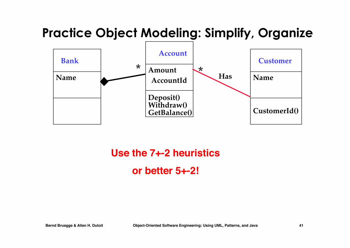
Practice Object Modeling: Simplify, Organize
Customer
Name
CustomerId()
Account
Amount
Deposit()Withdraw()GetBalance()
CustomerIdAccountIdAccountId
Bank
Name Has**
Use the 7+-2 heuristicsor better 5+-2!

Bernd Bruegge & Allen H. Dutoit Object-Oriented Software Engineering: Using UML, Patterns, and Java 42
UML Sequence Diagram

Bernd Bruegge & Allen H. Dutoit Object-Oriented Software Engineering: Using UML, Patterns, and Java 43
Message
UML first pass: Sequence diagram
:Time :Watch:WatchUser
Object
Activation
Sequence diagrams represent the behavior of a system as messages (“interactions”) between different objects
Actor
pressButton1()
Lifeline
blinkHours()
pressButton2()incrementMinutes()
:LCDDisplay
pressButton1and2()commitNewTime()stopBlinking()
refresh()
pressButton1()blinkMinutes()

Bernd Bruegge & Allen H. Dutoit Object-Oriented Software Engineering: Using UML, Patterns, and Java 44
Sequence Diagrams
• Used during analysis • To refine use case descriptions • to find additional objects
(“participating objects”) • Used during system design
• to refine subsystem interfaces • Instances are represented by
rectangles. Actors by sticky figures
• Lifelines are represented by dashed lines
• Messages are represented by arrows
• Activations are represented by narrow rectangles.
selectZone()
pickupChange()
pickUpTicket()
insertCoins()
TicketMachinePassenger
Focus on Controlflow
Messages ->Operations on
participating Object
zone2priceselectZone()insertCoins()pickupChange()pickUpTicket()
TicketMachine

Bernd Bruegge & Allen H. Dutoit Object-Oriented Software Engineering: Using UML, Patterns, and Java 45
Scenarios, use case and sequence diagrams
• A scenario is an instance of a use case describing a concrete set of actions (no alternative paths are in it)
• A use case is an abstraction that describes all possible scenarios involving the described functionality.
• Scenarios are used as examples for illustrating common cases;
• their focus is on understandability.
• Use cases are used to describe all possible cases;
• their focus is on completeness.

Bernd Bruegge & Allen H. Dutoit Object-Oriented Software Engineering: Using UML, Patterns, and Java 46
How to describe scenarios
• We describe a scenario using a template with three fields:
• The name of the scenario enables us to refer to it unambiguously. The name of a scenario is underlined to indicate that it is an instance.
• The participating actor instances field indicates which actor instances are involved in this scenario. Actor instances also have underlined names.
• The flow of events of a scenario describes the sequence of events step by step.

Bernd Bruegge & Allen H. Dutoit Object-Oriented Software Engineering: Using UML, Patterns, and Java 47
Scenario: an example

Bernd Bruegge & Allen H. Dutoit Object-Oriented Software Engineering: Using UML, Patterns, and Java 48
Sequence Diagrams can also model the Flow of Data
• The source of an arrow indicates the activation which sent the message
• Horizontal dashed arrows indicate data flow, for example return results from a message
Passenger
selectZone()
ZoneButton TarifSchedule Display
lookupPrice(selection)
displayPrice(price)
price
Dataflow…continued on next slide...

Bernd Bruegge & Allen H. Dutoit Object-Oriented Software Engineering: Using UML, Patterns, and Java 49
Sequence Diagrams: Iteration & Condition
• Iteration is denoted by a * preceding the message name • Condition is denoted by boolean expression in [ ] before
the message name
Passenger ChangeProcessor
insertChange(coin)
CoinIdentifier Display CoinDrop
displayPrice(owedAmount)
lookupCoin(coin)
price
[owedAmount<0] returnChange(-owedAmount)
Iteration
Condition
…continued on next slide...
…continued from previous slide...
*

Bernd Bruegge & Allen H. Dutoit Object-Oriented Software Engineering: Using UML, Patterns, and Java 50
Creation and destruction
• Creation is denoted by a message arrow pointing to the object • Destruction is denoted by an X mark at the end of the
destruction activation • In garbage collection environments, destruction can be used to
denote the end of the useful life of an object.
Passenger ChangeProcessor
…continued from previous slide...
Ticket
createTicket(selection)
free()
Creation of Ticket
Destruction of Ticket
print()
Bernd Bruegge & Allen H. Dutoit Object-Oriented Software Engineering: Using UML, Patterns, and Java 51
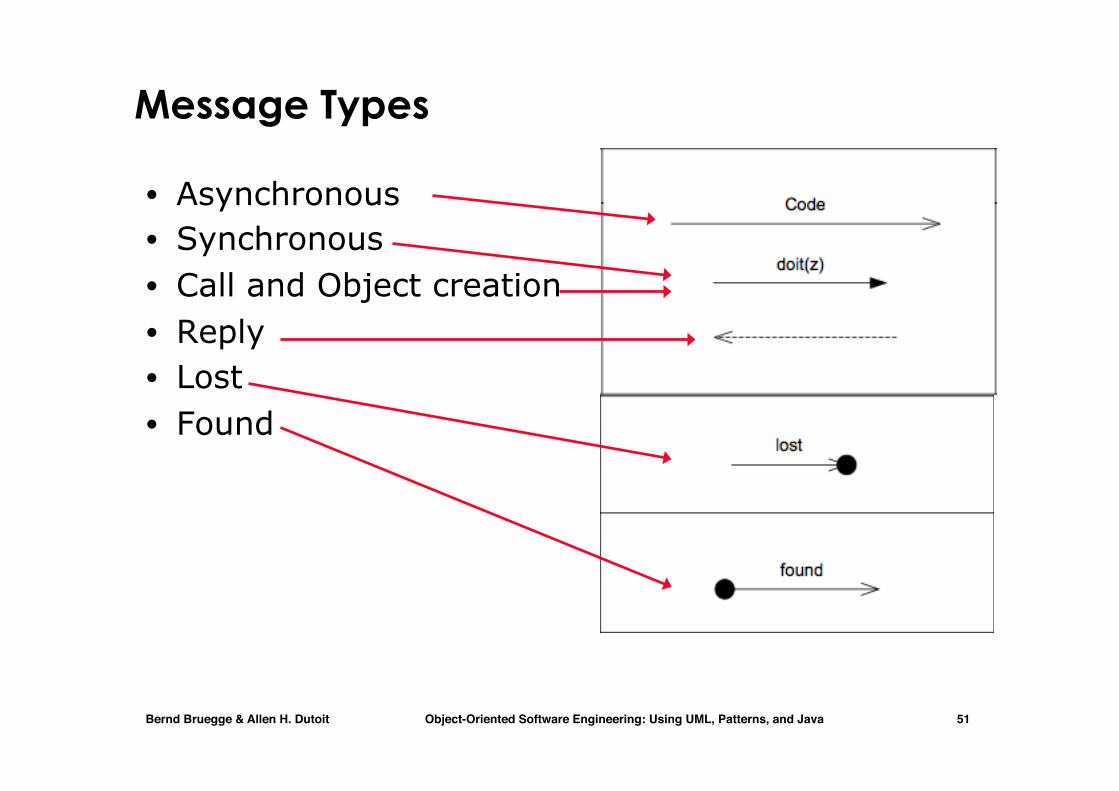
Message Types
• Asynchronous • Synchronous • Call and Object creation • Reply • Lost • Found

Bernd Bruegge & Allen H. Dutoit Object-Oriented Software Engineering: Using UML, Patterns, and Java 52
Sequence Diagram Properties
• UML sequence diagram represent behavior in terms of interactions
• Useful to identify or find missing objects • Time consuming to build, but worth the
investment • Complement the class diagrams (which
represent structure).
Bernd Bruegge & Allen H. Dutoit Object-Oriented Software Engineering: Using UML, Patterns, and Java 53
Interaction Diagrams

Bernd Bruegge & Allen H. Dutoit Object-Oriented Software Engineering: Using UML, Patterns, and Java 54
Interaction Diagrams
• UML 2.0: New concept of interaction fragments
• Before we go into detail with interaction fragments, let’s cover the concept of an interaction.

Bernd Bruegge & Allen H. Dutoit Object-Oriented Software Engineering: Using UML, Patterns, and Java 55
Interaction Diagrams
• Four types of interaction diagrams: • Sequence diagrams • We will not study the following (by now at least):
• Communication diagrams • Interaction overview diagrams • Timing diagrams
• The basic building block of an interaction diagram is the interaction
• An interaction is a unit of behavior that focuses on the observable exchange of information between connectable elements

Bernd Bruegge & Allen H. Dutoit Object-Oriented Software Engineering: Using UML, Patterns, and Java 56
Example of an Interaction: Sequence Diagram
Bernd Bruegge & Allen H. Dutoit Object-Oriented Software Engineering: Using UML, Patterns, and Java 57
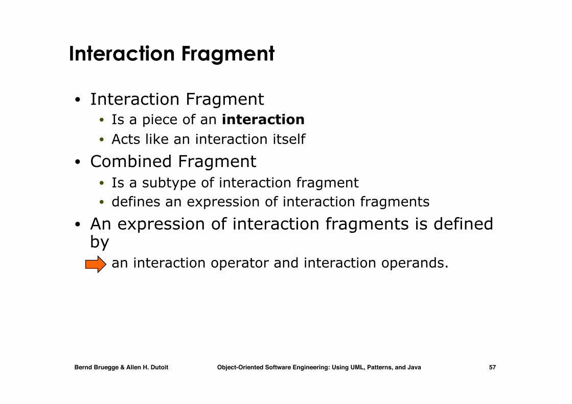
Interaction Fragment
• Interaction Fragment • Is a piece of an interaction • Acts like an interaction itself
• Combined Fragment • Is a subtype of interaction fragment • defines an expression of interaction fragments
• An expression of interaction fragments is defined by
• an interaction operator and interaction operands.

Bernd Bruegge & Allen H. Dutoit Object-Oriented Software Engineering: Using UML, Patterns, and Java 58
Example of a Combined Fragment using the alt operator
• The interaction operator alt indicates a choice of behavior between interaction fragments

Bernd Bruegge & Allen H. Dutoit Object-Oriented Software Engineering: Using UML, Patterns, and Java 59
Alt Operator
• The interaction operator alt indicates a choice of behavior between interaction fragments
• At most one interaction fragment (that is, an InteractionOperand) is chosen
• The chosen interaction fragment must have an explicit or implicit guard expression that evaluates to true at this point in the interaction
• A guard can be • a boolean expression (called InteractionConstraint) • else (a reserved word)
• If the fragment has no guard expression, true is implied.

Bernd Bruegge & Allen H. Dutoit Object-Oriented Software Engineering: Using UML, Patterns, and Java 60
Interaction Operators
• The following operators are allowed in the combination of interaction fragments:
• alt • opt • par • loop • critical • neg • assert • strict • seq • Ignore • consider
Bernd Bruegge & Allen H. Dutoit Object-Oriented Software Engineering: Using UML, Patterns, and Java 61
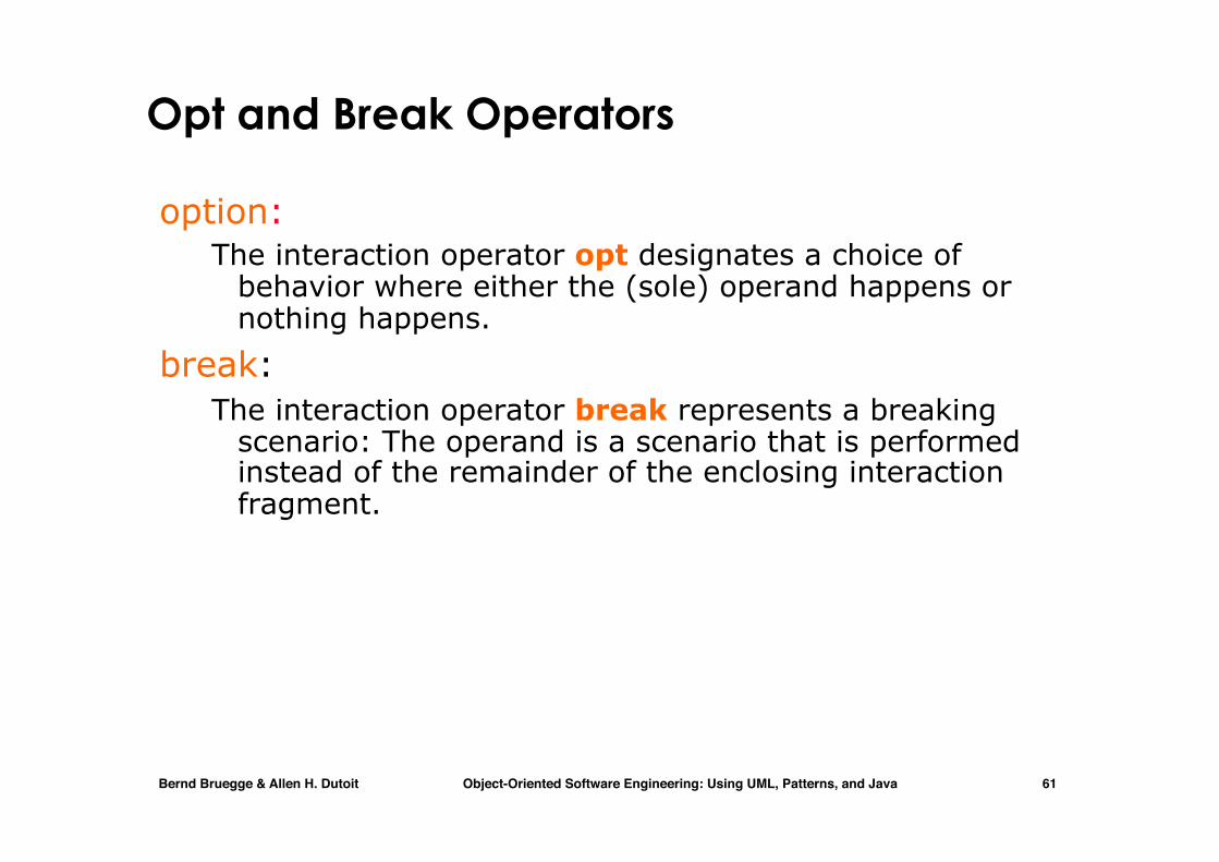
Opt and Break Operators
option: The interaction operator opt designates a choice of
behavior where either the (sole) operand happens or nothing happens.
break: The interaction operator break represents a breaking
scenario: The operand is a scenario that is performed instead of the remainder of the enclosing interaction fragment.
Bernd Bruegge & Allen H. Dutoit Object-Oriented Software Engineering: Using UML, Patterns, and Java 62
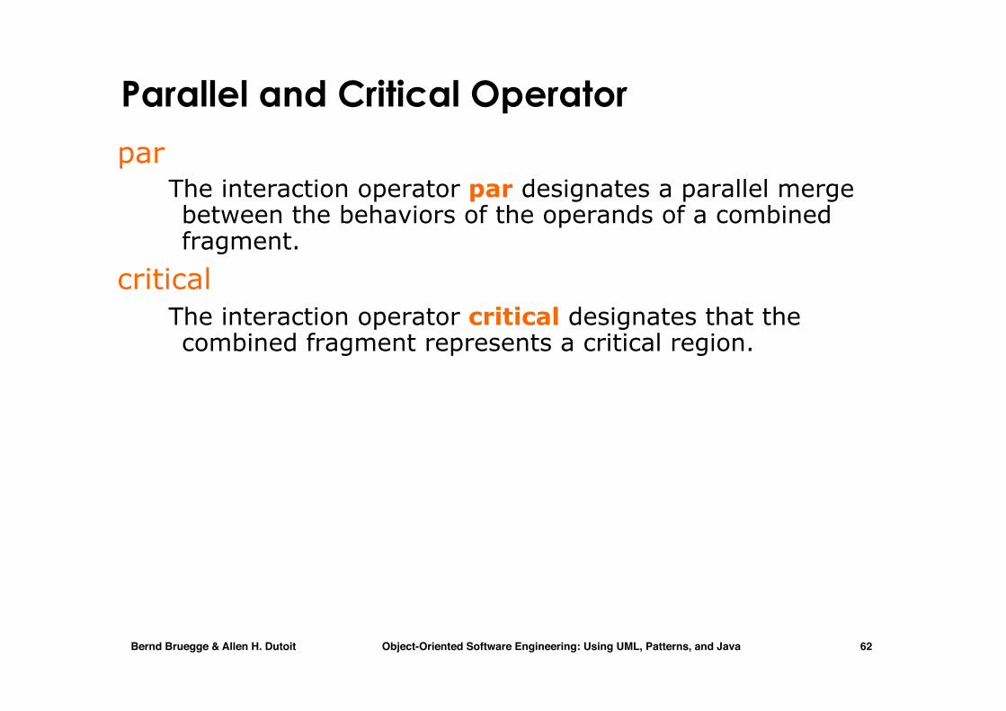
Parallel and Critical Operator
par The interaction operator par designates a parallel merge
between the behaviors of the operands of a combined fragment.
critical The interaction operator critical designates that the
combined fragment represents a critical region.

Bernd Bruegge & Allen H. Dutoit Object-Oriented Software Engineering: Using UML, Patterns, and Java 63
Example of a Critical Region Problem statement: The telephone Operator must make sure to
forward a 911-call from a Caller to the Emergency system before doing anything else. Normal calls can be freely interleaved.

Bernd Bruegge & Allen H. Dutoit Object-Oriented Software Engineering: Using UML, Patterns, and Java 64
UML Statechart Diagram

Bernd Bruegge & Allen H. Dutoit Object-Oriented Software Engineering: Using UML, Patterns, and Java 65
State diagrams and states
• State diagrams are used to give an abstract description of the behaviour of a system.
• This behaviour is analysed and represented as a series of events that can occur in one or more possible states.
• A state represents a step in the behaviour pattern of an object
• It is a configuration of the set of state-attributes of the behaving object
• Transition from one state to another is triggered by events
• An event may be either internal or external to the object
Bernd Bruegge & Allen H. Dutoit Object-Oriented Software Engineering: Using UML, Patterns, and Java 66
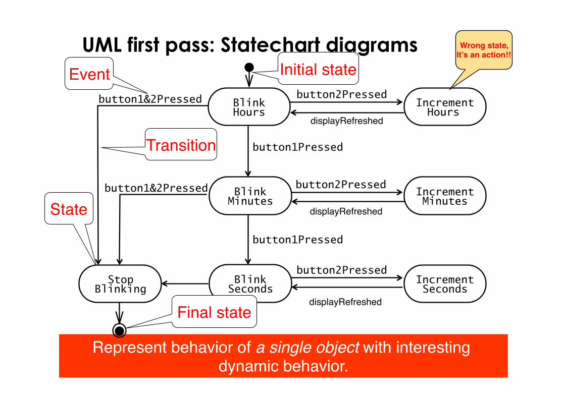
UML first pass: Statechart diagrams
State
Initial state
Transition
Event
Represent behavior of a single object with interesting dynamic behavior.
button1&2Pressed
button1Pressed
button2Pressed
button2Pressed
button2Pressed
button1Pressed
button1&2Pressed Increment Minutes
Increment Hours
Blink Hours
Blink Seconds
Blink Minutes
Increment Seconds
Stop Blinking
displayRefreshed
displayRefreshed
displayRefreshed
Wrong state,It’s an action!!
Final state
Bernd Bruegge & Allen H. Dutoit Object-Oriented Software Engineering: Using UML, Patterns, and Java 67
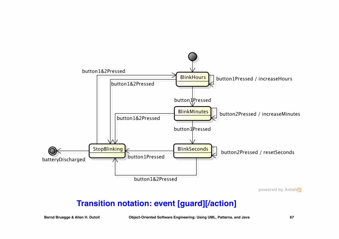
Transition notation: event [guard][/action]

Bernd Bruegge & Allen H. Dutoit Object-Oriented Software Engineering: Using UML, Patterns, and Java 68
Statechart for the Incident class

Bernd Bruegge & Allen H. Dutoit Object-Oriented Software Engineering: Using UML, Patterns, and Java 69
State machine diagram for 2Bwatch

Bernd Bruegge & Allen H. Dutoit Object-Oriented Software Engineering: Using UML, Patterns, and Java 70
Internal transitions in 2BWatch statechart

Bernd Bruegge & Allen H. Dutoit Object-Oriented Software Engineering: Using UML, Patterns, and Java 71
Review: UML Statechart Diagram Notation
State1Event(attr) [condition]/action
entry /actionexit/action
• Note: • Events are italics • Conditions are enclosed with brackets: [] • Actions are prefixed with a slash /
do/Activity
State2
Event with parameters attr
Guardcondition
Action
Event
Name ofState
Actions and Activities in State

Bernd Bruegge & Allen H. Dutoit Object-Oriented Software Engineering: Using UML, Patterns, and Java 72
Example of Concurrency within an Object
SettingUp
Readyto reset
Emitting
do/Dispense Cash
do/Eject Card
Cash taken
Card taken
SynchronizationSplitting control
Ready
Nested states
Nested diagrams: a portion of behavior is specified by a statechart within an higher level state

Bernd Bruegge & Allen H. Dutoit Object-Oriented Software Engineering: Using UML, Patterns, and Java 73
State diagram
Exit???

Bernd Bruegge & Allen H. Dutoit Object-Oriented Software Engineering: Using UML, Patterns, and Java 74
UML Activity Diagram

Bernd Bruegge & Allen H. Dutoit Object-Oriented Software Engineering: Using UML, Patterns, and Java 75
UML Activity Diagrams An activity diagram consists of nodes and edges • Nodes describe activities and objects
• Control nodes • Executable nodes
• Most prominent: Action • Object nodes
• E.g. a document
• Edge is a directed connection between nodes • There are two types of edges
• Control flow edges • Object flow edges

Bernd Bruegge & Allen H. Dutoit Object-Oriented Software Engineering: Using UML, Patterns, and Java 76
Activity diagrams
• In activity diagrams transitions from node to node happen automatically upon completion of activities
• Transitions do not depend upon the arrival of events as it happens in statecharts
• Activity diagrams represent the UML notation for the well known flowchart
• Each node in a flowchart represents an action to be executed.
• So it is not a state, but when applied to the program's state, it results in a transition to another state.

Bernd Bruegge & Allen H. Dutoit Object-Oriented Software Engineering: Using UML, Patterns, and Java 77
State vs Activity diagram
Statechart Activity diagram (flowchart)
action1
action2
action3
E2[test=1]/action2E2[test=0]/action4 test=1 test=0
action4
s4

Bernd Bruegge & Allen H. Dutoit Object-Oriented Software Engineering: Using UML, Patterns, and Java 78
Activity Diagrams: Grouping of Activities
• Activities may be grouped into swimlanes to denote the object or subsystem that implements the activities.
OpenIncident
AllocateResources
CoordinateResources
DocumentIncident
ArchiveIncident
Dispatcher
FieldOfficer

Bernd Bruegge & Allen H. Dutoit Object-Oriented Software Engineering: Using UML, Patterns, and Java 79
Activity diagram
Bernd Bruegge & Allen H. Dutoit Object-Oriented Software Engineering: Using UML, Patterns, and Java 80
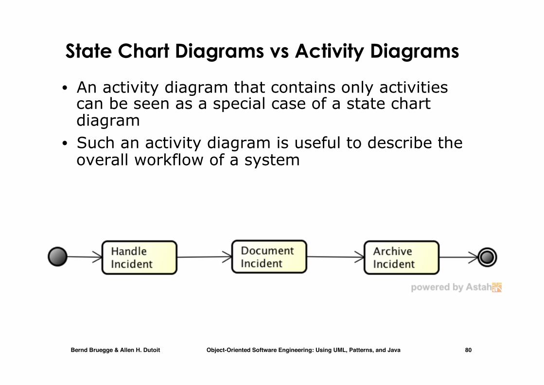
State Chart Diagrams vs Activity Diagrams
• An activity diagram that contains only activities can be seen as a special case of a state chart diagram
• Such an activity diagram is useful to describe the overall workflow of a system

Bernd Bruegge & Allen H. Dutoit Object-Oriented Software Engineering: Using UML, Patterns, and Java 81
Statechart Diagram vs Activity Diagram
Active Inactive Closed ArchivedIncident-Handled
Incident-Documented
Incident-Archived
Statechart Diagram for IncidentFocus on the set of attributes of a single abstraction (object, system)
Activity Diagram for Incident (Focus on actions performed and dataflow in a system)
TriggerlesstransitionCompletion of activity
causes state transition
Event causesstate transition

Bernd Bruegge & Allen H. Dutoit Object-Oriented Software Engineering: Using UML, Patterns, and Java 82
Example: Structure of the Text Book
Requirementselicitation (Ch.4)
Analysis (Ch.5)
System design
Problem Statement
functional modelnonfunctional requirements
analysis object model
dynamic model
class diagram
use case diagram
( Ch.6 & 7 )
statechart diagram
sequence diagram
Object Node
An object node is an activity node that indicates an instance of a particular classifier, possibly in a particular
state

Bernd Bruegge & Allen H. Dutoit Object-Oriented Software Engineering: Using UML, Patterns, and Java 83
Example: Structure of the Text Book (2)
System design (Ch. 6 & 7)
Object design (Ch. 8 & 9)
Implementation (Ch. 10)
object design model
design goals
subsystem decomposition
source code
Test (Ch. 11)
deliverable system
class diagram

Bernd Bruegge & Allen H. Dutoit Object-Oriented Software Engineering: Using UML, Patterns, and Java 84
Summary: Activity Diagram Example
UML Superstructure Specification, v2.1.2 335
Package BasicActivities
Nodes inherited from more general activities can be replaced. See RedefinableElement for more information on
overriding inherited elements, and Activity for more information on activity generalization. See children of ActivityNode
for additional semantics.
Notation
The notations for activity nodes are illustrated below. There are three kinds of nodes: action node, object node, and
control node. See these classes for more information.
Examples
This figure illustrates the following kinds of activity node: action nodes (e.g., Receive Order, Fill Order), object nodes
(Invoice), and control nodes (the initial node before Receive Order, the decision node after Receive Order, and the fork
node and Join node around Ship Order, merge node before Close Order, and activity final after Close Order).
Rationale
Activity nodes are introduced to provide a general class for nodes connected by activity edges.
Figure 12.50 - Activity node notation
Figure 12.51 - Activity node example (where the arrowed lines are only the non-activity node symbols)
Action node Object node Control nodes
Receive FillOrder
ShipOrderOrder
CloseOrder
SendInvoice
MakePayment
AcceptPayment
[orderaccepted]
[orderrejected]
Invoice
Initial node
Merge node
Final node
ActionObject node
Fork node
Join node
Control flow edge
Object flow edge
Decision node

Bernd Bruegge & Allen H. Dutoit Object-Oriented Software Engineering: Using UML, Patterns, and Java 85
Object flow (Details on new notation)
• Recent versions of UML adopt a solid line for object flow
• An alternative notation includes OutputPins/InputPins (they represent the objects delivered as output or consumed as input by activities)
OutputPin InputPin
Bernd Bruegge & Allen H. Dutoit Object-Oriented Software Engineering: Using UML, Patterns, and Java 86
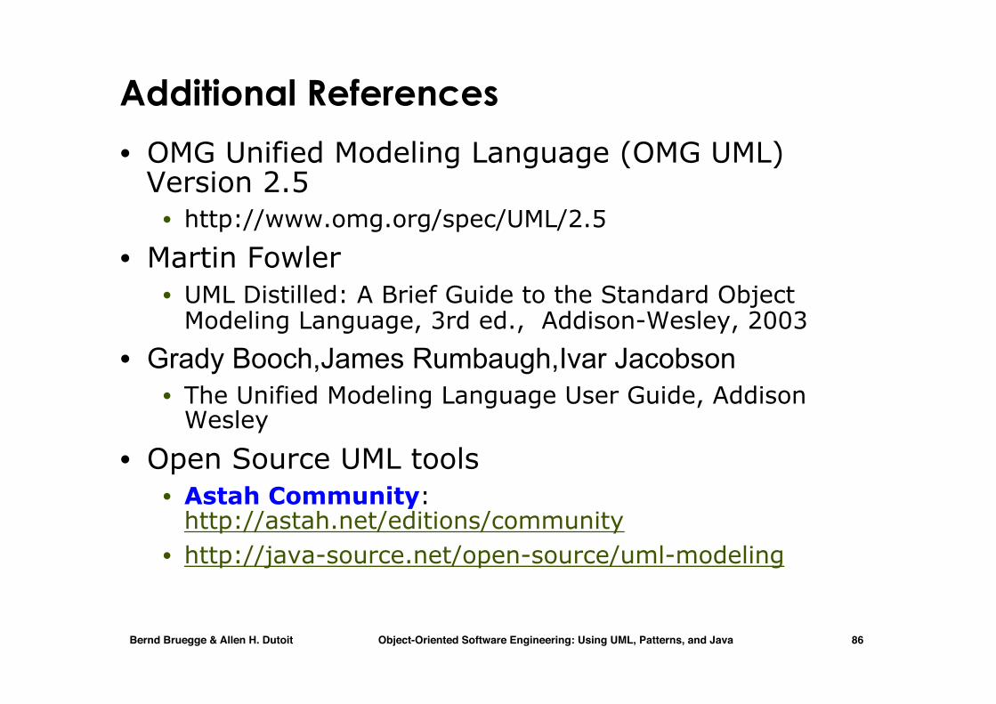
Additional References
• OMG Unified Modeling Language (OMG UML) Version 2.5
• http://www.omg.org/spec/UML/2.5
• Martin Fowler • UML Distilled: A Brief Guide to the Standard Object
Modeling Language, 3rd ed., Addison-Wesley, 2003 • Grady Booch,James Rumbaugh,Ivar Jacobson
• The Unified Modeling Language User Guide, Addison Wesley
• Open Source UML tools • Astah Community:
http://astah.net/editions/community • http://java-source.net/open-source/uml-modeling
Bernd Bruegge & Allen H. Dutoit Object-Oriented Software Engineering: Using UML, Patterns, and Java 87
UML Summary
• UML provides a wide variety of notations for representing many aspects of software development
• Powerful, but complex
• UML is a programming language • Can be misused to generate unreadable models • Can be misunderstood when using too many exotic
features
• We concentrated on a few notations: • Functional model: Use case diagram • Object model: class diagram • Dynamic model: sequence diagrams, statechart and
activity diagrams.