Embed Size (px)
Citation preview
Usin
g U
ML,
Pat
tern
s, an
d Ja
vaO
bjec
t-Ori
ente
d So
ftwar
e En
gine
erin
g
Chapter 7,
System Design: Addressing Design Goals

Bernd Bruegge & Allen H. Dutoit Object-Oriented Software Engineering: Using UML, Patterns, and Java 2
Overview
System Design I ü 0. Overview of System Design ü 1. Design Goals ü 2. Subsystem Decomposition
ü Architectural Styles
System Design II 3. Concurrency 4. Hardware/Software Mapping 5. Persistent Data Management 6. Global Resource Handling and Access Control 7. Software Control 8. Boundary Conditions

Bernd Bruegge & Allen H. Dutoit Object-Oriented Software Engineering: Using UML, Patterns, and Java 3
System Design
ü 2. Subsystem DecompositionLayers vs PartitionsCoherence/Coupling
4. Hardware/Software MappingSpecial PurposeBuy vs BuildAllocation of ResourcesConnectivity
5. DataManagement
Persistent ObjectsFile system vs Database
Access Control Listvs CapabilitiesSecurity
6. Global Resource Handlung
8. BoundaryConditions
InitializationTerminationFailure
Ø 3. ConcurrencyIdentification of Threads
7. Software Control
MonolithicEvent-DrivenConc. Processes
ü 1. Design GoalsDefinitionTrade-offs
Bernd Bruegge & Allen H. Dutoit Object-Oriented Software Engineering: Using UML, Patterns, and Java 4
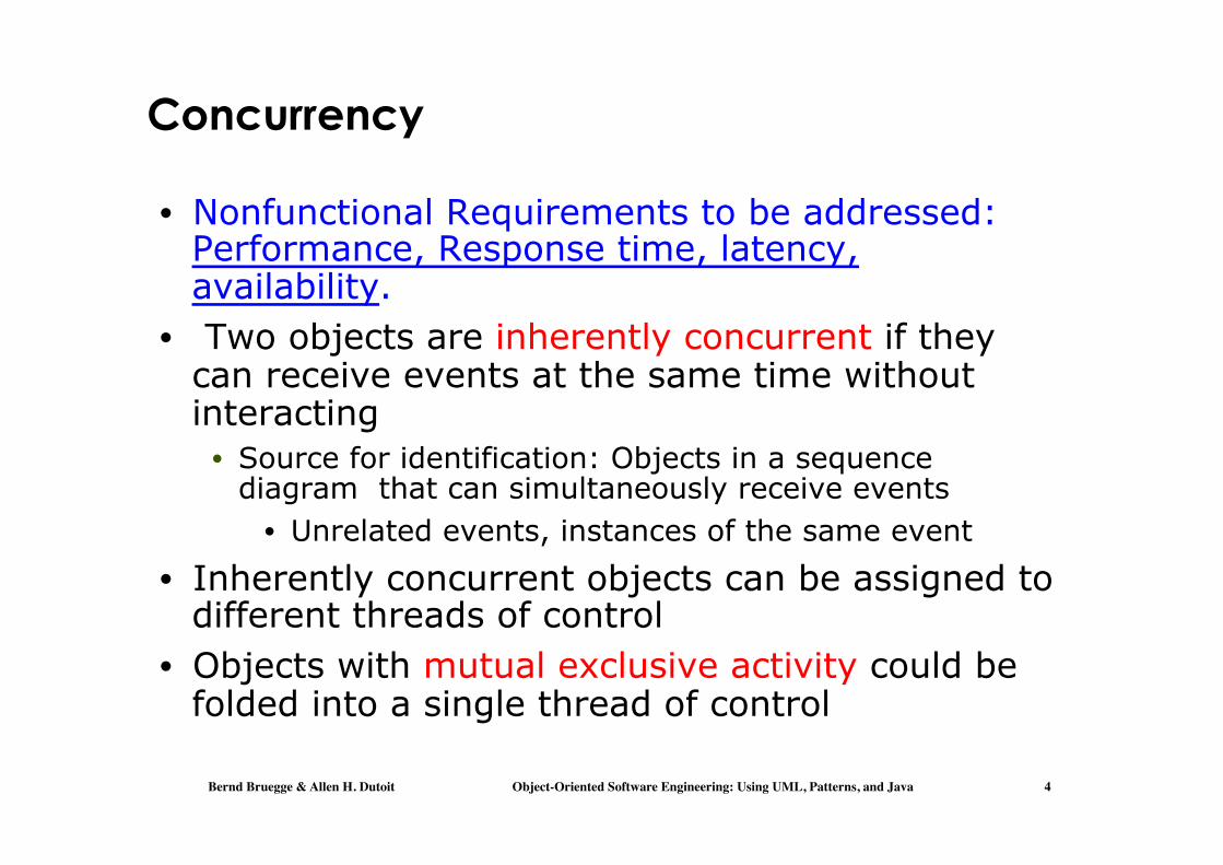
Concurrency
• Nonfunctional Requirements to be addressed: Performance, Response time, latency, availability.
• Two objects are inherently concurrent if they can receive events at the same time without interacting
• Source for identification: Objects in a sequence diagram that can simultaneously receive events
• Unrelated events, instances of the same event
• Inherently concurrent objects can be assigned to different threads of control
• Objects with mutual exclusive activity could be folded into a single thread of control

Bernd Bruegge & Allen H. Dutoit Object-Oriented Software Engineering: Using UML, Patterns, and Java 5
Thread of Control
• A thread of control is a path through a set of state diagrams on which a single object is active at a time
• A thread remains within a state diagram until an object sends an event to different object and waits for another event
• Thread splitting: Object does a non-blocking send of an event to another object.
• Concurrent threads can lead to race conditions. • A race condition (also race hazard) is a design
flaw where the output of a process depends on the specific sequence of other events.
• The name originated in digital circuit design: Two signals racing each other to influence the output.

Bernd Bruegge & Allen H. Dutoit Object-Oriented Software Engineering: Using UML, Patterns, and Java 6
Example: Problem with threads
:BankAccount c1:Customer c2:Customer
:WithdrawCtrl :WithdrawCtrl
getBalance()
200
withdraw(50)
setBalance(150)
getBalance()
200
withdraw(50)
setBalance(150)
computeNewBalance(200,50)
computeNewBalance(200,50)
Assume: Initial balance = 200
Final balance = 150 ??!
Thread 1
Thread 2
Should BankAccount be another Thread ?

Bernd Bruegge & Allen H. Dutoit Object-Oriented Software Engineering: Using UML, Patterns, and Java 7
Solution: Synchronization of Threads
c1:Customer c2:Customer :BankAccount :WithdrawCtrl
getBalance()
200
withdraw(50)
setBalance(150)
computeNewBalance(200,50)
Initial balance = 200
withdraw(50)
Single WithdrawCtrl Instance
Synchronized method
End balance = 100
Bernd Bruegge & Allen H. Dutoit Object-Oriented Software Engineering: Using UML, Patterns, and Java 8
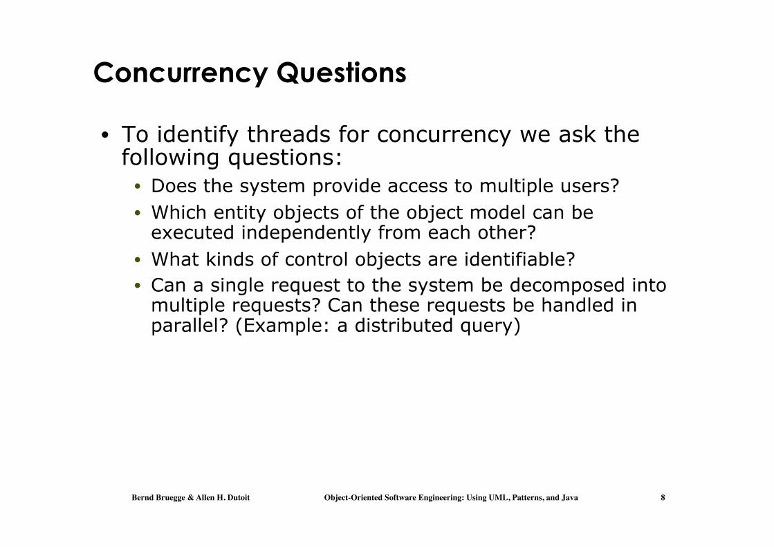
Concurrency Questions
• To identify threads for concurrency we ask the following questions:
• Does the system provide access to multiple users? • Which entity objects of the object model can be
executed independently from each other? • What kinds of control objects are identifiable? • Can a single request to the system be decomposed into
multiple requests? Can these requests be handled in parallel? (Example: a distributed query)

Bernd Bruegge & Allen H. Dutoit Object-Oriented Software Engineering: Using UML, Patterns, and Java 9
Implementing Concurrency
• Concurrent systems can be implemented on any system that provides
• Physical concurrency: Threads are provided by hardware
or • Logical concurrency: Threads are provided by software
• Physical concurrency is provided by multiprocessors and computer networks
• Logical concurrency is provided by threads packages.

Bernd Bruegge & Allen H. Dutoit Object-Oriented Software Engineering: Using UML, Patterns, and Java 10
Implementing Concurrency (2)
• In both cases, - physical concurrency as well as logical concurrency - we have to solve the scheduling of these threads:
• Which thread runs when? • Today’s operating systems provide a variety of
scheduling mechanisms: • Round robin, time slicing, collaborating processes,
interrupt handling • General question addresses starvation,
deadlocks, fairness -> Topic for researchers in operating systems
• Sometimes we have to solve the scheduling problem ourselves
• Topic addressed by software control (system design topic 7).

Bernd Bruegge & Allen H. Dutoit Object-Oriented Software Engineering: Using UML, Patterns, and Java 11
System Design
ü 2. Subsystem DecompositionLayers vs PartitionsCoherence/Coupling
Ø 4. Hardware/Software MappingSpecial PurposeBuy vs BuildAllocation of ResourcesConnectivity
5. DataManagement
Persistent ObjectsFilesystem vs Database
Access Control Listvs CapabilitiesSecurity
6. Global Resource Handlung
8. BoundaryConditions
InitializationTerminationFailure
ü 3. ConcurrencyIdentification of Threads
7. Software Control
MonolithicEvent-DrivenConc. Processes
ü 1. Design GoalsDefinitionTrade-offs

Bernd Bruegge & Allen H. Dutoit Object-Oriented Software Engineering: Using UML, Patterns, and Java 12
4. Hardware Software Mapping
• This system design activity addresses two questions:
• How shall we realize the subsystems: With hardware or with software?
• If hardware is chosen, how to proceed is out of the scope of the current course
• How do we map the object model onto the chosen hardware and/or software?
• Mapping the Objects: • Processor, Memory, Input/Output
• Mapping the Associations: • Network connections

Bernd Bruegge & Allen H. Dutoit Object-Oriented Software Engineering: Using UML, Patterns, and Java 13
Mapping Objects onto Hardware
• Control Objects -> Processor • Is the computation rate too demanding for a single
processor? • Can we get a speedup by distributing objects across
several processors? • How many processors are required to maintain a
steady state load? • Entity Objects -> Memory
• Is there enough memory to buffer bursts of requests? • Boundary Objects -> Input/Output Devices
• Do we need an extra piece of hardware to handle the data generation rates?
• Can the desired response time be realized with the available communication bandwidth between subsystems?

Bernd Bruegge & Allen H. Dutoit Object-Oriented Software Engineering: Using UML, Patterns, and Java 14
Mapping the Associations: Connectivity
• Describe the physical connectivity • (“Physical layer in the OSI reference model”)
• Describes which associations in the object model are mapped to physical connections
• Describe the logical connectivity (subsystem associations)
• Associations that do not directly map into physical connections
• In which layer should these associations be implemented?
• Informal connectivity drawings often contain both types of connectivity
• Practiced by many developers, sometimes confusing.

Bernd Bruegge & Allen H. Dutoit Object-Oriented Software Engineering: Using UML, Patterns, and Java 15
DistributedDatabaseArchitecture Tue, Oct 13, 1992 12:53 AM
Application Client
Application Client
Application Client
CommunicationAgent for
Application Clients
CommunicationAgent for
Application Clients
CommunicationAgent for Data
Server
CommunicationAgent for Data
Server
Local DataServer
Global DataServer
Global Data Server
Global Data
Server
OODBMS
RDBMS
Backbone Network
LAN
LAN
LANTCP/IP
Ethernet Cat 5Physical
Connectivity
Logical Connectivity
Example: Informal Connectivity Drawing

Bernd Bruegge & Allen H. Dutoit Object-Oriented Software Engineering: Using UML, Patterns, and Java 16
Logical vs Physical Connectivity and the relationship to Subsystem Layering
Application LayerApplication Layer
Presentation Layer
Session Layer
Transport Layer
Network Layer
Data Link Layer
Physical Layer
Bidirectional associa- tions for each layer
Presentation Layer
Session Layer
Transport Layer
Network Layer
Data Link Layer
Physical Layer
Processor 1 Processor 2
LogicalConnectivity
PhysicalConnectivity

Bernd Bruegge & Allen H. Dutoit Object-Oriented Software Engineering: Using UML, Patterns, and Java 17
Hardware-Software Mapping Difficulties
• Much of the difficulty of designing a system comes from addressing externally-imposed hardware and software constraints
• Certain tasks have to be at specific locations • Example: Withdrawing money from an ATM
machine • Some hardware components have to be used from a
specific manufacturer

Bernd Bruegge & Allen H. Dutoit Object-Oriented Software Engineering: Using UML, Patterns, and Java 18
Hardware/Software Mappings in UML
• A UML component is a building block of the system. It is represented as a rectangle with a tabbed rectangle symbol inside
• The Hardware/Software Mapping addresses dependencies and distribution issues of UML components during system design.

Bernd Bruegge & Allen H. Dutoit Object-Oriented Software Engineering: Using UML, Patterns, and Java 19
Two New UML Diagram Types
• Deployment Diagram: • Illustrates the distribution of components at run-time. • Deployment diagrams use nodes and connections to
depict the physical resources in the system.
• Component Diagram: • Illustrates dependencies between components at
design time, compilation time and runtime

Bernd Bruegge & Allen H. Dutoit Object-Oriented Software Engineering: Using UML, Patterns, and Java 20
Component Diagram Example
UML Interface
UML Component
reservations
update
Dependency.
Scheduler
Planner
GUI

Bernd Bruegge & Allen H. Dutoit Object-Oriented Software Engineering: Using UML, Patterns, and Java 21
UML Component Diagram
• Used to model the top-level view of the system design in terms of components and dependencies among the components. Components can be
• source code, linkable libraries, executables
• The dependencies (edges in the graph) are shown as dashed lines with arrows from the client component to the supplier component:
• The lines are often also called connectors • The types of dependencies are implementation language
specific
• Informally also called “software wiring diagram“ because it show how the software components are wired together in the overall application.

Bernd Bruegge & Allen H. Dutoit Object-Oriented Software Engineering: Using UML, Patterns, and Java 22
UML Superstructure Specification, v2.4.1 153
Figure 8.6 - A Component with two provided and three required interfaces
An external view of a Component is by means of Interface symbols sticking out of the Component box (external or black-box view). Alternatively, the interfaces and/or individual operations and attributes can be listed in the compartments of a component box (for scalability, tools may offer a way of listing and abbreviating component properties and behavior).
Figure 8.7 - Black box notation showing a listing of the properties of a component
For displaying the full signature of an interface of a component, the interfaces can also be displayed as typical classifier rectangles that can be expanded to show details of operations and events.
Figure 8.8 - Explicit representation of the provided and required interfaces, allowing interface details such as operation to be displayed (when desired).
Order
OrderableItem
«component» Person
Invoice
ItemAllocation
Tracking
Order«component»
«provided interfaces» OrderEntry Billing«required interfaces» Invoice create (...) registerPayment (...)
Person«component»Order
FindbyName()Create()GetDetails()
«use» «Interface»OrderEntry
Create()ValidateDetails()AddOrderline()
«Interface»
UML Interfaces: Lollipops and Sockets
• A UML interface describes a group of operations used or created by UML components.
• There are two types of interfaces: provided and required interfaces.
• A provided interface is modeled using the lollipop notation
• A required interface is modeled using the socket notation.
• A port specifies a distinct interaction point between the component and its environment.
• Ports are depicted as small squares on the sides of classifiers.
UML Superstructure Specification, v2.4.1 153
Figure 8.6 - A Component with two provided and three required interfaces
An external view of a Component is by means of Interface symbols sticking out of the Component box (external or black-box view). Alternatively, the interfaces and/or individual operations and attributes can be listed in the compartments of a component box (for scalability, tools may offer a way of listing and abbreviating component properties and behavior).
Figure 8.7 - Black box notation showing a listing of the properties of a component
For displaying the full signature of an interface of a component, the interfaces can also be displayed as typical classifier rectangles that can be expanded to show details of operations and events.
Figure 8.8 - Explicit representation of the provided and required interfaces, allowing interface details such as operation to be displayed (when desired).
Order
OrderableItem
«component» Person
Invoice
ItemAllocation
Tracking
Order«component»
«provided interfaces» OrderEntry Billing«required interfaces» Invoice create (...) registerPayment (...)
Person«component»Order
FindbyName()Create()GetDetails()
«use» «Interface»OrderEntry
Create()ValidateDetails()AddOrderline()
«Interface»

Bernd Bruegge & Allen H. Dutoit Object-Oriented Software Engineering: Using UML, Patterns, and Java 23
Component diagram – details from UML 2.4.1
UML Superstructure Specification, v2.4.1 153
Figure 8.6 - A Component with two provided and three required interfaces
An external view of a Component is by means of Interface symbols sticking out of the Component box (external or black-box view). Alternatively, the interfaces and/or individual operations and attributes can be listed in the compartments of a component box (for scalability, tools may offer a way of listing and abbreviating component properties and behavior).
Figure 8.7 - Black box notation showing a listing of the properties of a component
For displaying the full signature of an interface of a component, the interfaces can also be displayed as typical classifier rectangles that can be expanded to show details of operations and events.
Figure 8.8 - Explicit representation of the provided and required interfaces, allowing interface details such as operation to be displayed (when desired).
Order
OrderableItem
«component» Person
Invoice
ItemAllocation
Tracking
Order«component»
«provided interfaces» OrderEntry Billing«required interfaces» Invoice create (...) registerPayment (...)
Person«component»Order
FindbyName()Create()GetDetails()
«use» «Interface»OrderEntry
Create()ValidateDetails()AddOrderline()
«Interface»
154 UML Superstructure Specification, v2.4.1
An internal or white box view of a Component is where the realizing classifiers are listed in an additional compartment. Compartments may also be used to display a listing of any parts and connectors, or any implementing artifacts.
Figure 8.9 - A white-box representation of a component
The internal classifiers that realize the behavior of a component may be displayed using realization arrows.
Figure 8.10 - A representation of the realization of a complex component
Alternatively, the internal classifiers that realize the behavior of a component may be displayed nested within the component shape.
Order«component»
«provided interfaces» OrderEntry AccountPayable«required interfaces» Person
«realizations» OrderHeader LineItem
«artifacts» Order.jar
«component»Customer
CustomerImpl CustomerColl CustomerDef
UML Superstructure Specification, v2.4.1 153
Figure 8.6 - A Component with two provided and three required interfaces
An external view of a Component is by means of Interface symbols sticking out of the Component box (external or black-box view). Alternatively, the interfaces and/or individual operations and attributes can be listed in the compartments of a component box (for scalability, tools may offer a way of listing and abbreviating component properties and behavior).
Figure 8.7 - Black box notation showing a listing of the properties of a component
For displaying the full signature of an interface of a component, the interfaces can also be displayed as typical classifier rectangles that can be expanded to show details of operations and events.
Figure 8.8 - Explicit representation of the provided and required interfaces, allowing interface details such as operation to be displayed (when desired).
Order
OrderableItem
«component» Person
Invoice
ItemAllocation
Tracking
Order«component»
«provided interfaces» OrderEntry Billing«required interfaces» Invoice create (...) registerPayment (...)
Person«component»Order
FindbyName()Create()GetDetails()
«use» «Interface»OrderEntry
Create()ValidateDetails()AddOrderline()
«Interface»
UML Superstructure Specification, v2.4.1 155
Figure 8.11 - An alternative nested representation of a complex component
If more detail is required of the role or instance level containment of a component, then an internal structure consisting of parts and connectors can be defined for that component. This allows, for example, explicit part names or connector names to be shown in situations where the same Classifier (Association) is the type of more than one Part (Connector). That is, the Classifier is instantiated more than once inside the component, playing different roles in its realization. Optionally, specific instances (InstanceSpecifications) can also be referred to as in this notation. If the icon symbol is shown, the keyword «component» could be hidden.
If the parts have simple ports (ports with a single required or provided interface), then ball-and-socket notation can be used to represent connectors between those ports, and normal connector notation for assembly or delegation may be shown connected to the ball or socket symbol rather than to the port symbol itself.
If a part has no ports, or complex ports, the notation for connector wiring is as specified in Clause Composite Structures.
Interfaces that are exposed by a Component and notated on a diagram, either directly or through a port definition, may be inherited from a supertype component. These interfaces are indicated on the diagram by preceding the name of the interface by a forward slash. An example of this can be found in Figure 8.14, where “/orderedItem” is an interface that is implemented by a supertype of the Product component.
«component»Order
OrderHeader
LineItem
Person
OrderEntry
*
order
item
1

Bernd Bruegge & Allen H. Dutoit Object-Oriented Software Engineering: Using UML, Patterns, and Java 24
Component diagram – details from UML 2.4.1 / 2
156 UML Superstructure Specification, v2.4.1
Figure 8.12 - An internal or white-box view of the internal structure of a component that contains other components with simple ports as parts of its internal assembly
Artifacts that implement components can be connected to them by physical containment or by an «implement» relationship, which is an instance of the meta association between Component and Artifact.
Examples
Figure 8.13 - Example of an overview diagram showing components and their general dependencies
When a Dependency is wired from a Usage to an InterfaceRealization, the dependency arrow should be shown joining the socket to the lollipop.
A Dependency may be wired from a simple Port with a required interface to a simple Port to a provided interface, in which case it is a notational option to show the dependency arrow joining the socket to the lollipop.
A Dependency may be shown from a simple Port to an internal realizing Classifier to indicate that the interface provided or required by the Port is in fact provided or required by the Dependency’s supplier.
All of these options are shown in Figure 8.14.
«component»Store
«component»
:Order
«component»
:Product
«component»
:Customer
Person
Person
OrderableItem
OrderableItem
OrderEntry
OrderEntry
Account
Account
Order«component»
Account«component»
Product«component»
• A port specifies a distinct interaction point between the component and its environment.
• Ports are depicted as small squares on the sides of classifiers.
• The interfaces associated with a port specify the nature of the interactions that may occur over a port.

Bernd Bruegge & Allen H. Dutoit Object-Oriented Software Engineering: Using UML, Patterns, and Java 25
Component diagram – details from UML 2.4.1 / 3
UML Superstructure Specification, v2.4.1 157
Figure 8.14 - Example of a platform independent model of a component, its provided and required interfaces, and wiring through dependencies on a structure diagram.
Figure 8.15 shows a set of parts wired through ball-and-socket notation between simple ports. The diagram shows a binary connector between :ShoppingCart and :Order, a ternary connector between :Order, :Service and :Product, and a quaternary connector between :BackOrder, :Order, :Customer and :Organization.
Figure 8.15 -Example of a composite structure of components, with connector wiring between simple ports on parts (Note: “Client” interface is a subtype of “Person”).
Order«component»
LineItem
OrderHeader«focus»
*
concerns
Account«component»
Product«component»
OrderableItem
/orderedItem
account
AccountPayable
«component»
:BackOrder
«component»
:Order
«component»
:Product
«component»
:Customer
Person
Person
«component»
:Organization
«component»
:Service
Person
ClientOrderableItem
OrderableItemOrderableItem
OrderEntry«component»
:ShoppingCart OrderEntry
Where multiple components have simple ports that provide or require the same interface, a single symbol representing the interface can be shown, and lines from the components can be drawn to that symbol
UML Superstructure Specification, v2.4.1 165
Graphical paths
The graphic paths that can be included in structure diagrams are shown in Table 8.2.
Component has required Port (typed by Interface) See “Port”
Component has complex Port (typed by provided and required Interfaces)
See “Port”
Table 8.2 - Graphic paths included in structure diagrams
PATH TYPE NOTATION REFERENCE
Component realization See “ComponentRealization”
Table 8.3 - Graphic paths included in composite structure diagrams
PATH TYPE NOTATION REFERENCE
Assembly connector See “Connector” - also used as notation option for wiring between interfaces using Dependencies.
Delegate connector See “Connector”
Table 8.1 - Graphic nodes included in structure diagrams
NODE TYPE NOTATION REFERENCE
Name«component»
Name«component»
Component with a complex port

Bernd Bruegge & Allen H. Dutoit Object-Oriented Software Engineering: Using UML, Patterns, and Java 26
:HostMachine
:PC
:Scheduler
:Planner
MeetingDB: Database
Deployment Diagram Example
Dependency (between nodes)
Dependency (in a node)UML Node
UML Interface

Bernd Bruegge & Allen H. Dutoit Object-Oriented Software Engineering: Using UML, Patterns, and Java 27
• Deployment diagrams are useful for showing a system design after these system design decisions have been made:
• Subsystem decomposition • Concurrency • Hardware/Software Mapping
• A deployment diagram is a graph of nodes and connections (“communication associations”)
• Nodes are shown as 3-D boxes • Connections between nodes are shown as solid lines • Nodes may contain components
• Components can be connected by “lollipops” and “grabbers”
• Components may contain objects (indicating that the object is part of the component).
:PC
Deployment Diagram
:Server

Bernd Bruegge & Allen H. Dutoit Object-Oriented Software Engineering: Using UML, Patterns, and Java 28
ARENA Deployment Diagram
:ServerMachine
:UserMachine
:ArenaServer
:ArenaClient
:ArenaStorage
:AdvertisementServer
:MatchFrontEndPeer
:GamePeer

Bernd Bruegge & Allen H. Dutoit Object-Oriented Software Engineering: Using UML, Patterns, and Java 29
5. Data Management
• Some objects in the system model need to be persistent:
• Values for their attributes have a lifetime longer than a single execution
• A persistent object can be realized with one of the following mechanisms:
• Filesystem: • If the data are used by multiple readers but a
single writer • Database:
• If the data are used by concurrent writers and readers.

Bernd Bruegge & Allen H. Dutoit Object-Oriented Software Engineering: Using UML, Patterns, and Java 30
Data Management Questions
• How often is the database accessed? • What is the expected request (query) rate? The worst
case? • What is the size of typical and worst case requests?
• Do the data need to be archived? • Should the data be distributed?
• Does the system design try to hide the location of the databases (location transparency)?
• Is there a need for a single interface to access the data?
• What is the query format?

Bernd Bruegge & Allen H. Dutoit Object-Oriented Software Engineering: Using UML, Patterns, and Java 31
Mapping Object Models
• UML object models can be mapped to relational databases
• The mapping: • Each class is mapped to its own table • Each class attribute is mapped to a column in the table • An instance of a class represents a row in the table • One-to-many associations are implemented with a
buried foreign key • Many-to-many associations are mapped to their own
tables • Methods are not mapped

Bernd Bruegge & Allen H. Dutoit Object-Oriented Software Engineering: Using UML, Patterns, and Java 32
6. Global Resource Handling
• Discusses access control • Describes access rights for different classes of
actors • Describes how object guard against
unauthorized access.
Bernd Bruegge & Allen H. Dutoit Object-Oriented Software Engineering: Using UML, Patterns, and Java 33
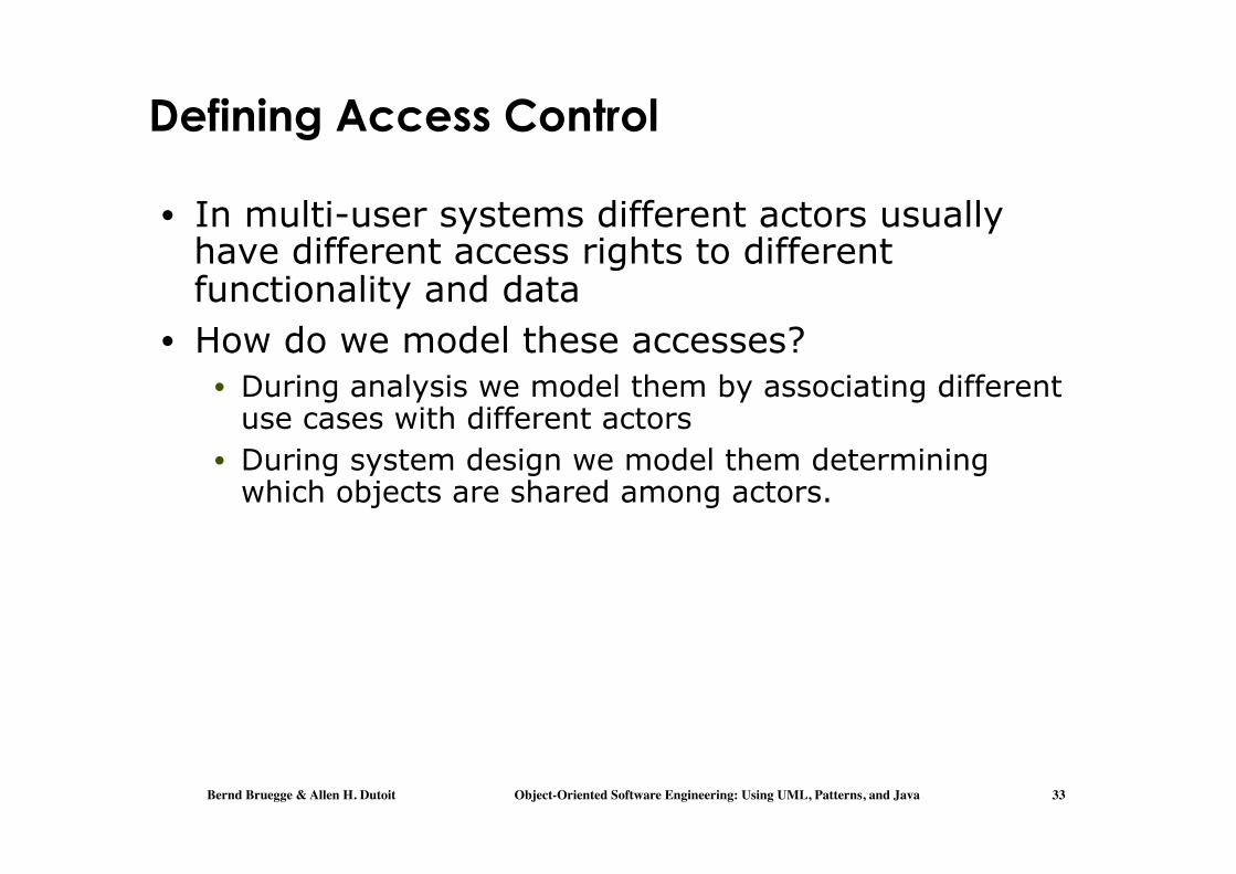
Defining Access Control
• In multi-user systems different actors usually have different access rights to different functionality and data
• How do we model these accesses? • During analysis we model them by associating different
use cases with different actors • During system design we model them determining
which objects are shared among actors.

Bernd Bruegge & Allen H. Dutoit Object-Oriented Software Engineering: Using UML, Patterns, and Java 34
Access Matrix
• We model access on classes with an access matrix:
• The rows of the matrix represents the actors of the system
• The column represent classes whose access we want to control
• Access Right: An entry in the access matrix. It lists the operations that can be executed on instances of the class by the actor.
Class 1 Class 2 Class 3 Actor 1 methodX()
methodZ() methodW()
Actor 2 MethodY() methodV()

Bernd Bruegge & Allen H. Dutoit Object-Oriented Software Engineering: Using UML, Patterns, and Java 35
Access Matrix Example
Arena League
Operator
LeagueOwner
Player
Spectator
Tournament
<<create>> archive() schedule() view() applyFor() view()
view()
<<create>> createUser() view ()
view ()
view() applyForPlayer()
view() applyForOwner()
<<create>> archive()
view() subscribe()
view() subscribe()
edit ()
Match
<<create>> end()
play() forfeit()
view() replay()
Actors
Classes Access Rights

Bernd Bruegge & Allen H. Dutoit Object-Oriented Software Engineering: Using UML, Patterns, and Java 36
Access Matrix Implementations (1 of 2)
• Global access table: Represents explicitly every cell in the matrix as a triple (actor,class, operation)
LeagueOwner, Arena, view() LeagueOwner, League, edit() LeagueOwner, Tournament, <<create>> LeagueOwner, Tournament, view() LeagueOwner, Tournament, schedule() LeagueOwner, Tournament, archive() LeagueOwner, Match, <<create>> LeagueOwner, Match, end() .

Bernd Bruegge & Allen H. Dutoit Object-Oriented Software Engineering: Using UML, Patterns, and Java 37
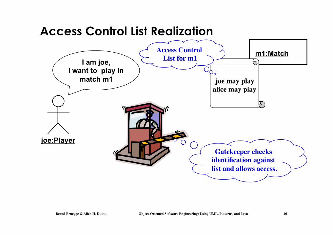
Access Matrix Implementations (2 of 2)
• Access control list • Associates a list of (actor,operation) pairs with each
class to be accessed. • Every time an instance of this class is accessed, the
access list is checked for the corresponding actor and operation.
• Capability • Associates a (class,operation) pair with an actor. • A capability provides an actor to gain control access to
an object of the class described in the capability.

Bernd Bruegge & Allen H. Dutoit Object-Oriented Software Engineering: Using UML, Patterns, and Java 38
Arena League
Operator
LeagueOwner
Player
Spectator
Tournament
<<create>> archive() schedule() view() applyFor() view()
view()
<<create>> createUser() view ()
view ()
view() applyForPlayer()
view() applyForOwner()
<<create>> archive()
view() subscribe()
view() subscribe()
edit ()
Match
<<create>> end()
play() forfeit()
view() replay()
Access Matrix Example
Player
Match
play() forfeit()

Bernd Bruegge & Allen H. Dutoit Object-Oriented Software Engineering: Using UML, Patterns, and Java 39
Player
Match
play() forfeit()
Bernd Bruegge & Allen H. Dutoit Object-Oriented Software Engineering: Using UML, Patterns, and Java 40
Access Control List Realization
joe:Player
m1:Match
joe may play���alice may play
I am joe, I want to play in
match m1
Gatekeeper checks identification against list and allows access.
Access Control List for m1

Bernd Bruegge & Allen H. Dutoit Object-Oriented Software Engineering: Using UML, Patterns, and Java 41
Capability Realization
joe:Player
m1:Match
Capability
Here’s my ticket, I’d like to play in
match m1
Gatekeeper checks if ticket is valid and
allows access.Ticket for���
match “m1”

Bernd Bruegge & Allen H. Dutoit Object-Oriented Software Engineering: Using UML, Patterns, and Java 42
Global Resource Questions
• Does the system need authentication? • If yes, what is the authentication scheme?
• User name and password? Access control list • Tickets? Capability-based
• What is the user interface for authentication? • Does the system need a network-wide name
server? • How is a service known to the rest of the
system? • At runtime? At compile time? • By Port? • By Name?

Bernd Bruegge & Allen H. Dutoit Object-Oriented Software Engineering: Using UML, Patterns, and Java 43
7. Decide on Software Control
Two major design choices: 1. Choose implicit control
• Rule-based systems, Logic programming 2. Choose explicit control
• Procedural languages: Centralized or decentralized

Bernd Bruegge & Allen H. Dutoit Object-Oriented Software Engineering: Using UML, Patterns, and Java 44
Centralized vs. Decentralized Designs
• (Explicit) Centralized Design • One control object or subsystem ("spider") controls
everything • Pro: Change in the control structure is very easy • Con: The single control object is a possible
performance bottleneck
• Decentralized Design • Not a single object is in control, control is distributed;
That means, there is more than one control object • Con: The responsibility is spread out • Pro: Fits nicely into object-oriented development

Bernd Bruegge & Allen H. Dutoit Object-Oriented Software Engineering: Using UML, Patterns, and Java 45
Centralized vs Decentralized Design/2
• (Explicit) Centralized control: • Procedure-driven: Control resides within program code. • Event-driven: Control resides within a dispatcher calling
functions via callbacks. • (Explicit) Decentralized control
• Control resides in several independent objects. • Examples: Message based system, RMI
• Possible speedup by mapping the objects on different processors, increased communication overhead.

Bernd Bruegge & Allen H. Dutoit Object-Oriented Software Engineering: Using UML, Patterns, and Java 46
Software Control
Explicit Control Implicit Control
Rule-based Control Logic Programming
Event-based Control
Procedural Control.
Centralized Control
Decentralized Control
Bernd Bruegge & Allen H. Dutoit Object-Oriented Software Engineering: Using UML, Patterns, and Java 47
Centralized vs. Decentralized Designs (2)
• Should you use a centralized or decentralized design?
• Take the sequence diagrams and control objects from the analysis model
• Check the participation of the control objects in the sequence diagrams
• If the sequence diagram looks like a fork => Centralized design
• If the sequence diagram looks like a stair => Decentralized design.

Bernd Bruegge & Allen H. Dutoit Object-Oriented Software Engineering: Using UML, Patterns, and Java 48
8. Boundary Conditions
• Initialization • The system is brought from a non-initialized state to
steady-state
• Termination • Resources are cleaned up and other systems are
notified upon termination
• Failure • Possible failures: Bugs, errors, external problems
• Good system design foresees fatal failures and provides mechanisms to deal with them.

Bernd Bruegge & Allen H. Dutoit Object-Oriented Software Engineering: Using UML, Patterns, and Java 49
Boundary Condition Questions
• Initialization • What data need to be accessed at startup time? • What services have to registered? • What does the user interface do at start up time?
• Termination • Are single subsystems allowed to terminate? • Are subsystems notified if a single subsystem
terminates? • How are updates communicated to the database?
• Failure • How does the system behave when a node or
communication link fails? • How does the system recover from failure?.

Bernd Bruegge & Allen H. Dutoit Object-Oriented Software Engineering: Using UML, Patterns, and Java 50
Modeling Boundary Conditions
• Boundary conditions are best modeled as use cases with actors and objects
• We call them boundary use cases or administrative use cases
• Actor: often the system administrator • Interesting use cases:
• Start up of a subsystem • Start up of the full system • Termination of a subsystem • Error in a subsystem or component, failure of a
subsystem or component.

Bernd Bruegge & Allen H. Dutoit Object-Oriented Software Engineering: Using UML, Patterns, and Java 51
Example: Boundary Use Case for ARENA
• Let us assume, we identified the subsystem AdvertisementServer during system design
• This server takes a big load during the holiday season
• During hardware software mapping we decide to dedicate a special node for this server
• For this node we define a new boundary use case ManageServer
• ManageServer includes all the functions necessary to start up and shutdown the AdvertisementServer.

Bernd Bruegge & Allen H. Dutoit Object-Oriented Software Engineering: Using UML, Patterns, and Java 52
ManageServer Boundary Use Case
Server Administrator
ManageServer
StartServer
ShutdownServer
ConfigureServer
<<include>>
<<include>>
<<include>>

Bernd Bruegge & Allen H. Dutoit Object-Oriented Software Engineering: Using UML, Patterns, and Java 53
Summary
• System design activities: • Concurrency identification • Hardware/Software mapping • Persistent data management • Global resource handling • Software control selection • Boundary conditions
• Each of these activities may affect the subsystem decomposition
• Two new UML Notations • UML Component Diagram: Showing compile time and
runtime dependencies between subsystems • UML Deployment Diagram: Drawing the runtime
configuration of the system.