Embed Size (px)
DESCRIPTION
Constrruction
Citation preview

Proposed Construction of two Bulk Liquid Storage
Tanks Review of Environmental Factors
December 2009

Copyright © Urbis Pty Ltd ABN 50 105 256 228 All Rights Reserved. No material may be reproduced without prior permission. While we have tried to ensure the accuracy of the information in this publication, the Publisher accepts no responsibility or liability for any errors, omissions or resultant consequences including any loss or damage arising from reliance in information in this publication. URBIS Australia Asia Middle East www.urbis.com.au
URBIS STAFF RESPONSIBLE FOR THIS REPORT WERE:
Director Tim Blythe Senior Consultant Naomi Daley Job Code SA3780 Report Number REFv1 xdisclaimerx

TABLE OF CONTENTS
SA3870-REFv1
Certification................................................................................................................................................i
1 Introduction.......................................................................................................................................1
2 Site Location and Setting ................................................................................................................2 2.1 The Site ...................................................................................................................................2 2.2 Surrounding Land Uses...........................................................................................................4
3 The Proposal.....................................................................................................................................5 3.1 Background to the Proposal ....................................................................................................5 3.2 Need for the Proposal..............................................................................................................6 3.3 Description of the Proposal .....................................................................................................7 3.3.1 Proposed Tanks ......................................................................................................................7 3.3.2 Extra Bund Capacity................................................................................................................8 3.3.3 Vapour Recovery Unit (VRU) ..................................................................................................8 3.4 Operational Details ..................................................................................................................8 3.4.1 Loading/ Unloading Procedures ..............................................................................................8 3.4.2 Spill Management..................................................................................................................10 3.5 Safety and Risk Management Procedures............................................................................10 3.5.1 Security Measures.................................................................................................................11 3.5.2 Fire Prevention and Control ..................................................................................................11
4 Statutory Framework .....................................................................................................................12 4.1 Environmental Planning and Assessment Act 1979 .............................................................12 4.2 Commonwealth Environment Protection and Biodiversity Conservation Act 1999...............12 4.3 SEPP (Major Development) 2005 .........................................................................................12 4.4 SEPP (Infrastructure) 2007 ...................................................................................................13 4.5 SEPP 33 – Hazardous and Offensive Development.............................................................13 4.6 Additional Relevant Legislation .............................................................................................13 4.6.1 Protection of the Environment Operations Act 1997 .............................................................13 4.6.2 Other......................................................................................................................................14 4.7 Sydney Ports Guidelines and Policies...................................................................................14 4.7.1 Port Botany Development Code 2009...................................................................................14 4.7.2 Traffic Management Plan Guidelines 2007 ...........................................................................14 4.7.3 Green Port Guidelines ...........................................................................................................15 4.7.4 Port Botany Land Use Safety Study Overview Report 1996.................................................15
5 Consultation....................................................................................................................................16
6 Environmental Impact Assessment .............................................................................................17 6.1 Overview................................................................................................................................17 6.2 Assessment Method..............................................................................................................17 6.3 Clause 228 Consideration .....................................................................................................17 6.4 Detailed Environmental Assessment.....................................................................................20 6.5 Environmental considerations ...............................................................................................20 6.5.1 Water Quality Impacts ...........................................................................................................20 6.5.2 Soil and Groundwater Impacts ..............................................................................................21 6.5.3 Air Quality ..............................................................................................................................22 6.5.4 Acoustic Impacts ...................................................................................................................23 6.6 Traffic and Transport .............................................................................................................23

TABLE OF CONTENTS
SA3870-REFv1
6.7 Safety and Security ...............................................................................................................24 6.8 Other considerations .............................................................................................................25 6.8.1 Visual impacts .......................................................................................................................25 6.8.2 Waste Management ..............................................................................................................28 6.8.3 Heritage .................................................................................................................................28 6.8.4 Cumulative impacts ...............................................................................................................29
7 Mitigation Measures.......................................................................................................................30
8 Conclusion......................................................................................................................................31
Appendix A Plans of the Proposed Development .....................................................................32
Appendix B Port Botany Development Code 2009 Checklist...................................................33
Appendix C Green Port Guidelines Checklist ............................................................................34
Appendix D Final Hazard Analysis ..............................................................................................35
CERTIFICATION
SA3870-REFv1 Page i
Certification
This Review of Environmental Factors, prepared on behalf of Terminals Pty Ltd, provides a true and fair review of the Proposal in relation to its potential effects on the environment. It addresses to the fullest extent possible, all matters affecting or likely to affect the environment as a result of the Proposal. To the best of my knowledge, the information contained in this Review of Environmental Factors is neither false nor misleading.
Name of the person(s) and who prepared the REF:
Naomi Daley
Position and Qualifications of the person(s) who prepared the REF:
Senior Consultant – Planning and Design (Urbis); BArts (Human Geography) and GradDipURP (University of Sydney)
Signature:
Date:
November 2009


INTRODUCTION
SA3870-REFv1 Page 1
1 Introduction This Review of Environmental Factors has been prepared by Urbis on behalf of Terminals Pty Ltd pursuant to Section 111 of the Environmental Planning and Assessment Act 1979 to consider the environmental impact associated with the proposed installation of two bulk liquid storage tanks (of Ethanol and PULP) within Terminals ‘Stage 5’ land.
The purpose of this report is to:
Describe the existing site context;
Identify and evaluate all matters affecting or likely to affect the environment by reason of the activity;
Consider the relevant matters as required under Part 5 of the Environmental Planning and Assessment Act and Regulations; and
Consider and respond to matters raised by Sydney Ports Authority in correspondence dated 9 November 2009.
This report has been prepared with technical and specialist information from Terminals Pty Ltd.

SITE LOCATION AND SETTING
Page 2 SA3870-REFv1
2 Site Location and Setting
2.1 The Site The subject site is located within the Port Botany Industrial Area and is leased from the Sydney Ports Corporation. The site is located at 9 Simblist Road, Port Botany, as illustrated in the locality map below. The site is legally described as Lot 1 in Deposited Plan 622687.
Figure 1 – Locality Map
This application seeks to construct two additional tanks within the area known as Stage 5, which applies to the portion of the site outlined in red on the aerial photograph below.
Picture 1 – Aerial Photograph with portion of site subject to application in red

SITE LOCATION AND SETTING
SA3870-REFv1 Page 3
There are currently 65 tanks on the entire Terminals site with an overall storage capacity of 52,780m³.
In the ‘Stage 5’ area of the site, which is the portion of the site subject to this application, there is currently one tank (Tank 270) with a storage capacity of 5,000m³. The tank sits within a large vacant sealed and bunded area. Adjacent is an entry gate leading to the loading/unloading facilities, an unused area to the south east of the site and various other pieces of ancillary equipment.
Photographs of the existing development on the site are included below.
Picture 2 – Tank 270 Picture 3 – Existing bunded areas to contain the two proposed tanks
Picture 4 – Location of proposed bunded area in the south east corner of the site (approved under Mod 1)
Picture 5 – Entry gate with existing loading/unloading facilities

SITE LOCATION AND SETTING
Page 4 SA3870-REFv1
2.2 Surrounding Land Uses Port Botany has been developed for industrial purposes relating to shipping and port based activities. The majority of companies with operations in the Port Botany area involve industries relating to container imports/exports and logistics, petroleum products, liquid petroleum gas and liquid chemicals and include:
Qenos Pty Ltd;
Origin Energy Pty Ltd;
Vopak Terminals Australia Pty Ltd.
The closest residential development to the site is that of Phillip Bay, approximately 1.5km from the site.

THE PROPOSAL
SA3870-REFv1 Page 5
3 The Proposal
3.1 Background to the Proposal Terminals Pty Ltd is an Australian company providing service to industry in the form of bulk liquid storage facilities leased to customers at strategic Australian port locations. These port locations are at Port Botany (Sydney), Coode Island (Melbourne), Corio (Geelong) and Osborne (South Australia). Whilst each of these facilities is wholly owned by Terminals, they are situated on land that is leased from the relevant Port Authority.
Port Botany is one of the three major ports in New South Wales with one of the predominant trades being petroleum products, liquefied petroleum gas (LPG), and liquid chemicals. The majority of industries in the Port Botany industrial region are involved in the storage and distribution of these products and are located on Friendship Road in the vicinity of the existing and proposed Terminals storage facility.
Terminals have owned and operated the existing bulk liquid storage and handling facility for hazardous and non-hazardous bulk liquids at Port Botany since 1979. The original facility has undergone three subsequent expansions, each involving the construction of additional storage capacity. A summary of these previous development applications is provided in the table below.
Table 1: Previous Development Applications
Stage Number of tanks
Additional Capacity (m³)
Date of DA and ref (where available)
Comments
1 (original DA)
20 22,350 (original capacity)
1979
2 12 5,810 1980
3 28 18,820 1987
4 4 800 1989 (840/45/D – 161/88)
5 12 (actually constructed one - Tank 270)
20,250 (actually constructed 5,000
1997 (DA 249/96) Consent for ‘expansion of an existing bulk liquid storage facility with associated loading/unloading facilities, pipelines, safety systems, landscaping and fencing’.
Works known as the ‘Stage 5’. This development was legally
commenced by the construction of 1 x 5,000 m3 tank (Tank 270) and the construction of a large hard surfaced area surrounded by a bund wall.
5A Additional 2 Additional 20,000
September 2009 (DA 249/96 Mod 1)
The proposed modification involves the installation of 2 larger tanks, each with a capacity of 10,000m3, rather than the approved 12 smaller tanks; increasing the storage capacity from 20,250m3 to 25,000m3. This development was named as ‘Stage 5A’.
THE PROPOSAL
Page 6 SA3870-REFv1
3.2 Need for the Proposal Since the time when the consent for DA 246/96 was granted, the demand for particular products has shifted, with the previous modifications to the 1997 consent responding to this change. The original approval was for twelve smaller tanks of varying sizes, designed to be filled with different industrial/liquid fuel products. Due to various factors, only one of the twelve tanks was built (Tank 270). Since the time of the 1997 approval, there has been a shift in the type of fuel needing to be stored, with demand focusing on unleaded and diesel fuel. This trend is to be reflected in the consolidation of the eleven approved smaller tanks into two larger ones.
In April 2009, legislation has been enacted into NSW under the Biofuel (Ethanol Content) Amendment Act 2009, prescribing certain minimum requirements for using Ethanol as a fuel. Clause 6 states:
6 Minimum ethanol requirement for volume fuel sellers
(1) A volume fuel seller must ensure that the volume of ethanol sold by the seller (in petrol-ethanol blend) during a relevant period is not less than the minimum ethanol percentage of the total volume of all petrol (including petrol-ethanol blend) sold by the seller during the relevant period.
(2) The "minimum ethanol percentage" is:
(a) 2% for any relevant period before a relevant period to which paragraph (b) or (c) applies, or
(b) 4% for a relevant period that starts on or after 1 January 2010 other than a relevant period to which paragraph (c) applies, or
(c) 6% for a relevant period that starts on or after 1 January 2011.
(3) Only ethanol that complies with a biofuel sustainability standard may be counted towards the volume of ethanol sold for the purposes of this section.
8 Regular unleaded petrol to be E10
(1) A primary wholesaler must not sell regular unleaded petrol unless the petrol is E10. "E10" is defined in section 3 (1) to mean petrol-ethanol blend that contains between 9% and 10% ethanol by volume, being ethanol that complies with a biofuel sustainability standard.
(2) This section takes effect on 1 July 2011 or on a later date that is prescribed by the regulations as the start date for the purposes of this section.
To comply with this requirement, it was planned to put ethanol and PULP into existing facility but with other business opportunities it was deemed better logistics of constructing two new tanks at stage V with these chemicals and in fact making room for new chemical storage at existing site. Hence it is proposed to install 2 x 1,750m3 storage tanks for the storage of Ethanol and Premium Unleaded Petrol (PULP). In addition, pipework and blending facilities would be installed in the existing Loading Bay to enable petrol / ethanol blends to be loaded into trucks for subsequent distribution.
It is anticipated that PULP would come into the Terminal via tying to an existing dockline from the Bulk Liquids Berth, whilst Ethanol is anticipated to arrive via road tankers from local Ethanol manufacturers. Some Ethanol could also be imported via the Bulk Liquids Berth.
The proposed development is also important to support the competitive fuels market in NSW. The proposed tanks will support the independent fuels market and petrol station operators. This is particularly relevant in an environment of rising fuel prices as well as broader questions regarding genuine competition in the fuels market.

THE PROPOSAL
SA3870-REFv1 Page 7
3.3 Description of the Proposal The proposed works, within the Stage 5A area of the site, are as follows:
Construction of two new 1,750m³ capacity storage tanks for storage of Ethanol and Premium Unleaded Petrol to supplement the 2 x 10,000m³ Unleaded Petrol (ULP) (as approved in DA249/96 MOD 1). Additional comments are provided in Section 3.3.1 below;
Increase the storage capacity of the development by 3,500 m³;
Install pipework and blending facilities at the existing loading bay to accommodate petrol / ethanol blends;
Extend an existing ship to shore 250 mm dockline to stage 5A for unloading PULP and any other products from ships;
A new road tanker unloading pump to be installed at the existing truck loading/unloading bay;
The storage tank for PULP will be fitted with an internal floating roof – considered as ‘best practice’ for storage of product of this type
The approved Vapour Recovery Unit (VRU) to recover petroleum vapours from the tanker loading operations and return it to the respective storage tank;
The storage tank for Ethanol will have vapour emissions treated through the existing vapour control systems on site.
An extension to the proposed bunded area to meet the legislated requirement under AS1940 to contain 100 per cent of the contents of the largest tank plus fire water, and.
An extension to the proposed fire-fighting system to provide for protection of the facility.
Refer to Appendix A – Plans of the Proposed Development.
3.3.1 Proposed Tanks It is proposed to construct two additional storage tanks within the ‘Stage 5A’ portion of the site, each with a capacity of 1,750m³. The tanks are to be 11.8 metres wide and have an overall height of 17.0 metres. These two tanks will be used to ethanol and premium unleaded petrol and also be suitable for the storage of diesel fuel, jet fuel and general hydrocarbons.
The PULP tank (T271) will have a primary steel roof as well as an internal floating roof in order to minimise vapour emissions and will be fitted with water sprays and foam injection. The possibility of overfill will be significantly reduced by the installation of level gauges and overfill devices.
The Ethanol tank (T272) will have a fixed roof fitted with nitrogen blanketing in the headspace and connected to the existing Vapour Emission Control System (VECS). It will also be fitted with water sprays and foam injection. The possibility of overfill will be significantly reduced by the installation of level gauges and overfill devices.
Protection systems on the two storage tanks will include:
Procedures for liquid transfers, stormwater management, regular maintenance and inspection;
Fully welded and tested carbon steel plate construction;
Remote emergency shutdown valves;
Connection to the new Vapour Recovery Unit for road tanker loading;
Internal floating roofs for petrol and connection to vapour emission control for ethanol to minimise air emissions to industry good practice standards;
Fire management plan and radiation protection systems for potential adjacent tank fire source;
THE PROPOSAL
Page 8 SA3870-REFv1
Emergency response plan including communication with site control centre;
Structural integrity tests conducted every 10 years in accordance with AS1940;
Non-return valves in pipelines at the bulk liquids berth, tanks and for unloading operations, to prevent backflow;
Containment of liquid within proposed extra capacity bund;
Tank foundations will have an impervious membrane with ‘tell-tale’ drains installed for leak detection of the tank base;
High level and redundant High level alarm system; and
Emergency alarms.
3.3.2 Extra Bund Capacity In response to AS1940, which requires a bund to be able to contain the contents of the largest tank as well as an appropriate amount of rainwater, an extra capacity bund is already part of the modified approval for stage 5 (DA249/96 MOD 1). This will be marginally increased to accommodate the two extra tanks. It is proposed to locate this bund to the east of the existing bund wall.
The bunded area will have a sump for the collection of rainwater and possible spills. Water collected in the sump will be sampled and inspected prior to release. Should the water be contaminated, it will be pumped to an approved (DECC) waste treatment facility. If the water is not contaminated it will be released to stormwater via an oil/water separator by opening a manual valve.
3.3.3 Vapour Recovery Unit (VRU) A new Vapour Recovery Unit is to be located near the existing truck loading bay. The VRU is already approved under DA 249/96 Mod 1.
3.4 Operational Details The proposal is to be integrated into the management and operational structure of the existing bulk liquid storage facility. This includes operating under a Safety Management System and Environmental Manual. The facility is certificated to ISO 9001 Quality Management System and ISO 14001 Environmental Management System.
It is proposed to use the management, technical and operational staff from the existing Terminals facility.
3.4.1 Loading/ Unloading Procedures The operation of the site will not deviate from the current approval in place.
The loading of fuels is essentially a ‘self service’ arrangement but with appropriate safeguards, training, accreditation and management practices.
When the driver enters the site via Simblist Road (through the use of a key card) an electric access card starts a timer that limits the time the driver has on site. If this time is exceeded the security monitoring company will investigate the cause of delay. Loading interlock systems are in place to ensure that the driver connects up to the vapour discharge, earth bonding connection and compartment overfill protection before loading can commence. Automatic bottom loading is via purpose built tanker loading arms and trucks will load at a rate of up to 2400 litres per minute into each truck compartment.
There are a number of protection features already in operation at the loading/unloading bay, including:
Procedures for operations, operator training, maintenance, training of maintenance employees, contractor safety training and emergencies;

THE PROPOSAL
SA3870-REFv1 Page 9
Specific driver training in loading and unloading operations, liquid transfers and stormwater management;
Requirement that the driver must be present during manual loading operations;
Local Emergency Stop stations have been installed that initiate pump shutdowns and tank isolations;
Substantial roofed area to minimise the potential contamination of stormwater;
Facilities to contain spills or contaminated rainwater and to return this material to the existing liquid effluent tank and/or alternative storage tank;
Fire water hose points;
Foam supplies for foam attachment points;
Foam and dry powder fire extinguishers;
Road tanker loading operations to be provided with foam protection;
Loading ceases if air line breaks as air supply fails;
Spillage containment of tanker compartment contents in the event of a spill;
Continuous closed circuit television monitoring in place;
Safety air breaks to ensure wheels remain in locked position and ensure that the truck cannot leave with the loading hose attached;
Truck electric’s isolations switch;
Scully system lead designed to dissipate any static electricity build up and to prevent overflow condition by shutting down loading system upon detecting a high level in any compartment;
Additional high level detection in vapour knock out pot that shuts down the loading system;
Dead man recognition requiring the driver to press the key pad every 2.5 minutes to verify that loading is continuing safely;
Dry brake couplings to avoid leaks and spills while connecting and disconnecting hoses;
Detonation arrester located as close to truck vapour hose connection point as practical to reduce the possibility of a flame flash back to/from the road tanker;
Recovery of displaced vapours from truck head space in VRU and return of resulting liquid back to the appropriate storage tank;
A first-flush and separator pit designed for spill containment.
For safety reasons, no queuing of trucks is permitted within the site. It is submitted that given the current and expected low volumes of truck movements together with the likelihood of such movements to occur across any 24 hour period, that the potential for congestion on Simblist Road will be negligible.
The proposal will include new procedures and hardware including:
Procedures for operations, operator training, maintenance, training of maintenance employees, contractor safety training and emergencies;
“Automatic” starting of Vapour Recovery Unit in the event of truck being filled;
Specific driver training in loading and unloading operations, liquid transfers and stormwater management;
Requirement that the driver must be present during manual loading and unloading operations;
THE PROPOSAL
Page 10 SA3870-REFv1
Local Emergency Stop stations have been installed that initiate pump shutdowns and tank isolations;
Facilities to contain spills or contaminated rainwater and to return this material to the existing liquid effluent tank and/or alternative storage tank;
Fire water hose points;
Foam supplies for foam attachment points;
Foam and dry powder fire extinguishers;
Road tanker loading operations to be provided with foam and deluge spray protection;
Additional continuous closed circuit television monitoring in place; and
Dry brake couplings to avoid leaks and spills while connecting and disconnecting hoses;
3.4.2 Spill Management Specific operating and emergency procedures exist for the management of spills and vary according to the magnitude of the spill as outlined below.
Very Minor Spill (<20 litres)
Contain spill within the bunded area and/or by isolation of stormwater discharge from the site and/or local containment;
Add appropriate absorbent; and
Dispose of absorbent to an approved Environment Protection Authority facility.
Minor Spill (<500 litres)
Contain spill within the bunded area and/or by isolation of stormwater discharge from the site and/or local containment;
Pump contained liquid to the liquid effluent storage tanks; and
Transport liquid to an approved DECC waste treatment facility.
Major Spill (>500 litres)
Contain spill within the bunded area or by isolation of stormwater discharge from the site;
Pump liquid to the liquid effluent storage tanks and/or separate, clean, storage tank on site;
Check the quality of the liquid by analyses; and
Pending the results of the analysis:
− Return the liquid to the original tank
− Return the liquid to the client for reprocessing
− Classify the liquid for another use
− Transport the liquid to the Environment Protection Authority’s approved aqueous waste management facility at Lidcombe.
3.5 Safety and Risk Management Procedures Terminals’ safety management strategy is to conduct operations such that risks to staff, the public, the environment and property are rigidly controlled.

THE PROPOSAL
SA3870-REFv1 Page 11
Terminals has a Safety Management Manual which details the applicable elements of Process Safety Operations to Terminals’ operations. All incidents, accidents and unusual occurrences on the Terminals site are reported and investigated.
3.5.1 Security Measures The Terminals site is surrounded by approximately 1.5 kilometres of high security boundary fences and entry to the site is via one of three gates and is gained by security card authorisation. Internal and external patrols are carried out after hours and over weekends. In addition, the main site has 16 CCTV cameras monitoring the site and four cameras in the Stage 5 area. All movements are recorded on hard disk and kept for up to six months.
3.5.2 Fire Prevention and Control Fire protection for the two proposed storage tanks and Loading Bay deluge system is via two diesel operated fire water pumps in the existing site with 1,400m³ of water in storage and continuous replenishment from Sydney Water reticulation. The existing foam supply is adequate to supply the two new tanks and piping will be installed to deliver this foam. If the foam and fire water systems are activated an alarm is raised to the NSW Fire Brigade.
An automatic foam deluge delivery system will be installed in the truck filling bays in addition to AS1940 requirements. This system will be activated by infrared detectors located in the truck fill, which are inspected and checked as per AS1851 requirements. Portable fire extinguishers and foam supplies are also available in the loading bay. At the exit of the loading bay is a manual fire call point as well as emergency exit points for personnel.

STATUTORY FRAMEWORK
Page 12 SA3870-REFv1
4 Statutory Framework This section describes the statutory framework under which the Proposal will be assessed.
4.1 Environmental Planning and Assessment Act 1979 This Review of Environmental Factors (REF) considers the requirements of Clause 228 of the Environmental Planning and Assessment Regulation 2000 and Sections 5A and 111 of the EP&A Act 1979 (See Section 6.3).
The provisions of the SEPP (Major Development) 2005 allow the work proposed to be carried out under Part 5 of the EP&A Act 1979.
4.2 Commonwealth Environment Protection and Biodiversity Conservation Act 1999
In assessing the impact of the Proposal for the purposes of the Commonwealth EPBC Act 1999 it is considered that the proposal will not pose a significant impact on:
a declared World Heritage Property
a National Heritage place
a declared Ramsar wetland
Commonwealth listed migratory species
Commonwealth listed threatened species or endangered community
Commonwealth marine areas
Commonwealth land
The considerations above apply to the proposed development assessed in this REF. However, the safeguards provided in Section 7 need to be implemented to ensure these considerations are met.
4.3 SEPP (Major Development) 2005 The proposal is subject to the provisions of SEPP (Major Development) 2005. In summary:
Clause 6 identifies projects to which Part 3A of the Act applies with reference to Schedule 1 to 3.
Under Schedule 2, Clause 22, Port and wharf facilities that have a capital investment of more than $30 million are subject to Part 3A of the Act. The proposed value of works is less than $30 million and is not subject to Part 3A of the EP&A Act 1979.
The site is located on land identified on the Land Application Map as detailed in Schedule 3 of the SEPP, Part 20 – Three Ports Site. The proposal is defined as ‘port facilities’ as per Clause 2 of Part 20. Clause 6 of Part 20 states that a number of Clauses do not apply and accordingly the project is not subject to Part 3A of the EP&A Act 1979.
In accordance with Clause 10A – Development does not require consent under Part 4, is specified in Schedule 7 and does not require consent under Part 4 of the Act. Schedule 7, Clause 2 states that ‘port facilities’ on land owned by a public authority within the Three Ports site and being development of not more than $30 million. Discussions with Sydney Ports confirm that the proposal is consistent with the definition of ‘port facilities’.

STATUTORY FRAMEWORK
SA3870-REFv1 Page 13
Further Clause 10A, has the consequence that the removal of the requirement for development consent under Part 4 of the Act is subject to an environmental assessment and approval requirements under Part 5 of the Act. The determining authority for Port facilities under Part 5 is Sydney Ports Authority.
4.4 SEPP (Infrastructure) 2007 SEPP Infrastructure 2007 contains consultation requirements within Part 2 of the SEPP.
Extensive consultation occurred for the two large petrol tanks at stage V during last year. As this is a small addition next to these tanks and within their shadow of environmental and risk impact; repeating this comprehensive consultation process was not considered necessary but alternatively planned to consult with our industrial neighbours and the local community through the Port Botany Neighbourhood Liaison Group and BEREPA. Consultation with local community group called BEREPA (Botany & Eastern Region Environmental Protection Agency) occurred on 15th December. Consultation with Port Botany Neighbourhood Liaison Group is planned for their next meeting on 23rd February 2010.
4.5 SEPP 33 – Hazardous and Offensive Development State Environmental Planning Policy No.33- Remediation of Land (SEPP 33) requires specific matters to be considered for proposals that are ‘potentially hazardous’ or ‘potentially offensive’ as defined in the policy. The proposed development is classified as ‘potentially hazardous industry’ which is defined as:
A development for the purposes of any industry which, if the development were to operate without employing any measures (including, for example, isolation from existing or likely future development on other land) to reduce or minimise its impact in the locality or on the existing or likely future development on other land, would pose a significant risk in relation to the locality:
(a) to human health, life or property, or
(b) to the biophysical environment,
and includes a hazardous industry and a hazardous storage establishment.
A Final hazard analysis has been prepared and is submitted with the development application as the proposal comprises development that is classified as potentially hazardous industry. A Final Hazard Analysis is attached at Appendix D.
4.6 Additional Relevant Legislation The relevant provisions of the following Acts have been considered, where applicable, to the proposed development. The Proposal is considered to be consistent with all relevant provisions.
4.6.1 Protection of the Environment Operations Act 1997 The Protection of the Environment Operations Act 1997 aims to protect, restore and enhance the quality of the environment in New South Wales, having regard to the need to maintain ecologically sustainable development and is administered by the Department of Environment and Climate Change (DECC). ‘Petroleum products storage’ is listed in Schedule 1 of the Act and is therefore declared to be a scheduled activity.
Clause 47 of the Act states that an Environment Protection License is required for development of a premise for the purpose of a scheduled activity, meaning the proposal requires such a license.
Terminals will be applying for an EPA licence amendment to cover the proposed changes in conjunction with the recently approved petrol tanks before commissioning.

STATUTORY FRAMEWORK
Page 14 SA3870-REFv1
4.6.2 Other The current and proposed operations have considered the applicability of the following legislation and the applicable licences or approvals have been obtained. The proposal satisfied the requirements of:
Pipelines Act 1967
Water Management Act 2000
Airports Act 1996
Further, Terminals will be notifying WorkCover of the proposed new storage tank depots under the Dangerous Goods notification requirements and also keeping WorkCover notified of any potential MHF changes when relevant.
4.7 Sydney Ports Guidelines and Policies
4.7.1 Port Botany Development Code 2009 The proposal has comprehensively considered the Port Botany Development Code 2007. Generally, the proposal complies with all applicable criteria. A full compliance table is provided as Appendix 2.
4.7.2 Traffic Management Plan Guidelines 2007 The Traffic Management Plan Guidelines 2007 have been considered as part of the proposal and further commentary on traffic and transport implications are provided in Section 6.6.
Generally the proposed increase in traffic movements are considered marginal and equate to around 2 additional trucks per day. Further, for safety reasons, no queuing of trucks is permitted within the site. It is submitted that given the current and expected low volumes of truck movements together with the likelihood of such movements at the time of loading and unloading to occur across any 24 hour period, that the potential for congestion on Simblist Road will be negligible.
Within the Guidelines, the site is located within the A1 Precinct Plan 1 for Port Botany. The preparation of TMP will be undertaken as per the above condition of consent and generally will:
Assess the traffic impacts of the proposed operational and infrastructure arrangement.
Detailed traffic management measures to ameliorate any impacts
Consider and address any special provisions such as emergency vehicles, heavy vehicles and the like
Consultation with Sydney Ports, adjoining properties and relevant agencies/authorities.
Consider any improvements, if any, required to the Simblist Road entrance to improve truck access moveability.
Condition 20 of DA246/96 (MOD 1) required the preparation of a Traffic Management Plan that:
Describes the traffic volumes and movements to occur during construction and operation
Detail the proposed measures to minimise the impact of construction and operation traffic on the surrounding network, including route selection, driver behaviour and vehicle maintenance; and
Detail the procedures to be implemented in the event of a complaint from the public regarding construction and operation traffic.
Again, the detailed preparation of a TMP is anticipated to be conditioned as a part of the approval and to be required prior to construction of the tanks.

STATUTORY FRAMEWORK
SA3870-REFv1 Page 15
4.7.3 Green Port Guidelines A checklist has been completed that addresses the relevant criteria and requirements of the Green Port Guidelines and is attached as Appendix C.
4.7.4 Port Botany Land Use Safety Study Overview Report 1996 The Port Botany Land use Safety Study Overview report has been considered in the Final Hazard Analysis (attached at Appendix D) and the report notes that “the two proposed tanks to the stage 5 area have no significant impact to the cumulative individual risk contours (for future development planning) as presented in the Port Botany Land Use Safety Study by DUAP in 1996”.

CONSULTATION
Page 16 SA3870-REFv1
5 Consultation Extensive consultation occurred for the recently approved two large petrol tanks at stage V during last year. As this is a small addition next to these tanks and within their shadow of environmental and risk impact; repeating this comprehensive consultation process was not considered necessary but alternatively planned to consult with our industrial neighbours and the local community through the Port Botany Neighbourhood Liaison Group and BEREPA. Consultation with local community group called BEREPA (Botany & Eastern Region Environmental Protection Agency) occurred on 15th December. Consultation with Port Botany Neighbourhood Liaison Group is planned for their next meeting on 23rd February 2010.
The Sydney Ports Port Botany Expansion Community Consultative Committee would also be notified by Sydney Ports as part of the assessment process.
A pre-lodgement meeting was undertaken with Sydney Ports on 28 October 2009. The REF has addressed SPC’s relevant issues as raised in the meeting and minutes.
ENVIRONMENTAL IMPACT ASSESSMENT
SA3870-REFv1 Page 17
6 Environmental Impact Assessment
6.1 Overview Section 6 provides an environmental impact assessment for the proposed works at Terminals Port Botany facility.
In essence, the implications arising from the proposal are not significant for the reasons that:
The two proposed tanks will be located in the approved and already contained location.
Notwithstanding the increase in storage capacity, the overall impact in terms of vehicle movements to and from the site will be negligible.
Given the proposed size of the tanks it will not result in any physical or visual impact on surrounding properties and are well removed from any sensitive land uses.
Any likely environmental impacts are proposed to be mitigated through appropriate measures.
The proposal is acceptable from a risk assessment analysis.
6.2 Assessment Method The methodology applied to the environmental assessment for the proposed works is as follows:
Identifying potential environmental risks/impacts associated with the construction and operational phases of the project;
Evaluating identified risks/impacts to determine the potential for occurrence and degree of severity; and,
Identifying and determining suitable environmental management procedures and control measures appropriate for planned works.
6.3 Clause 228 Consideration Clause 228 of the Environmental Planning and Assessment Regulation 2000 details factors which must be taken into account when assessing the impact of an activity on the environment.
Table 6-1 addresses the factors requiring consideration under Section 228. Applicable environmental management procedures and control measures are summarised in Section 7.

ENVIRONMENTAL IMPACT ASSESSMENT
SA3870-REFv1 Page 18
Table 6-1 Factors for Consideration under Clause 228 of Environmental Planning and Assessment Regulation 2000
Factor Impact Assessment Mitigation Actions
Any environmental impact on a community? No
Any transformation of a locality? Yes - The tanks will physically transform the locality.
The siting of the tanks is appropriately located wholly within the leased area of the site. The height of the tanks is appropriate given the site context.
Any environmental impact on the ecosystems of the locality? No
Any reduction of the aesthetic, recreational, scientific or other environmental quality or value of a locality?
No
Any effect on a locality, place or building having aesthetic, anthropological, archaeological, architectural, cultural, historical, scientific or social significance or other special value for present or future generations?
No See Section 6.8.3
Any impact on the habitat of any protected fauna (within the meaning of the National Parks and Wildlife Act 1974)?
No
Any endangering of any species of animal, plant or other form of life, whether living on land, in water or in the air?
No
Any long-term effects on the environment? No See Section 3.3 and Section 6.5
Any degradation of the quality of the environment? No The REF has assessed the issues of water, air, noise and hazard. See Section 3.3 and Section 6.5
Any risk to the safety of the environment? Yes – the proposal is potentially hazardous or offensive.
A Final Hazard Analysis has been prepared as part of the submission. This documents the likely risks to the safety of the environment and mitigation measures. See Section 3.3 and Section 6.5
Any reduction in the range of beneficial uses of the environment? No
Any pollution of the environment? No The REF has assessed the issues of water, air, noise and hazard. See Section 3.3 and Section 6.5

ENVIRONMENTAL IMPACT ASSESSMENT
SA3870-REFv1 Page 19
Factor Impact Assessment Mitigation Actions
Any environmental problems associated with the disposal of waste? No – The management of waste is as per current operations
Any increased demands on resources (natural or otherwise) which are, or are likely to become, in short supply?
No
Any cumulative environmental effect with other existing or likely future activities? No Proposal marginally increases the volume of bulk liquid storage on the site. All proposed impacts have been appropriately mitigated.

ENVIRONMENTAL IMPACT ASSESSMENT
Page 20 SA3870-REFv1
6.4 Detailed Environmental Assessment A number of environmental aspects were identified and raised by Sydney Ports Authority (as listed in the pre-DA minutes from 28 October 2009) as being applicable to the site and require additional environmental assessment, including:
Environmental (noise, air, water quality, contamination, flora and fauna)
Traffic and Transport
Safety and Security
Other (heritage, visual impacts, cumulative impacts)
Further assessment of the above items are provided below.
6.5 Environmental considerations The following environmental considerations have been considered as part of the proposal:
Noise
Air
Water quality
Contamination
Flooding
Coastal hazard
Threatened species
Native vegetation
Acid Sulphate Soils
Discussion on the key environmental issues of relevance to the proposal are provided below. A Sydney Ports Authority Green Port Guidelines checklist is provided in Appendix B.
6.5.1 Water Quality Impacts The water quality impact and management for stage 5 is the same as detailed in the stage 5a modification proposal for two 10,000 cubic metre tanks as approved under DA No 246/96-MOD 1. The same infrastructure and management controls for these additional two 1750 cubic metre storage tanks involving ethanol, petrol and general hydrocarbons as well as construction activities will be implemented. GHD has previously prepared an assessment of the potential implications associated with surface water quality associated with the approved stage 5a modifications. This proposal is consistent with this assessment.
The key matters raised in the previous assessment are summarised as follows:
The site is located on reclaimed land at Port Botany and does not include any natural waterways. The nearest waterway is Botany Bay, located approximately 125m east of the site. The site operates as a bulk liquid terminal and there is the potential for stormwater to be contaminated by hydrocarbons and suspended solids from sealed surfaces such as roadways, car parks and bunded areas.

ENVIRONMENTAL IMPACT ASSESSMENT
SA3870-REFv1 Page 21
The site has an environmental protection licence (L1048) issued by the EPA under the Protection of the Environment Operations Act 1997 (POEO Act) which does not permit pollution of waters. The majority of the site is sealed surfaces and issues associated with surface water are managed in accordance with Terminals Port Botany Environmental Management Manual such that all liquid waste and wastewater is contained and stored prior to transport off-site to an EPA licensed treatment facility.
Surface water management practices focus on separating runoff from different catchments to ensure that only clean water is discharged offsite. This practice allows stormwater from individual catchments to be segregated and disposed of according to its quality.
Construction impacts would be minor and related to erosion and sedimentation from disturbed surfaces.
Operational impacts would be the same as those that are currently experienced at the site and would be mitigated using the same measures already implemented on the site.
Construction phase impacts should be managed by implementing a Construction Soil and Water Management Plan developed in accordance with the strategies outlined in Landcom Soil and Construction, Managing Urban Stormwater (Landcom, 2004). These should include:
- General site practices and responsibilities, such as keeping surrounding roadways clean of any sediment transport offsite by construction vehicles, and ensuring that plant and machinery is well maintained and does not have oil or fuel leaks;
- Stockpile and topsoil management practises to control erosion and sedimentation such as placing sediment control devices downstream of any exposed areas, including stockpiles and excavated areas. These may include straw bales, sediment fences, turbidity barriers, stabilised site accesses, diversions and catch drains; and
- Monitoring the quality of discharges to the stormwater system.
Operation – the Environmental Management Manual will be updated to reflect the proposed changes to the site. The proposal must be operated in accordance with the updated manual, inclusive of spill response measures.
As requested by Sydney Ports, details on the waste water management of ethanol is required. In summary:
Waste water management for ethanol is the same system in that likely areas of leaks/spills are contained; designated conservatively contaminated (whether are or not) then collected & transported off site for treatment at an EPA approved facility.
Stormwater areas of driveways and bunds are tested, then if not contaminated are discharged through API separator to stormwater drains. If contaminated, waste water is collected & transported off site for treatment at an EPA approved facility.
Overall, the subject proposal is subject to the current appropriate mitigation measures and will not have an impact upon the existing conditions and the established infrastructure already in place.
6.5.2 Soil and Groundwater Impacts In terms of the current proposal, the extent of site excavation required to support the proposed tanks is anticipated to be minimal, being less than 300mm for the tank bases. Given the small extent of surface disturbance it is considered that the extent of soil and groundwater impacts arising from the proposal is minimal.
Consistent with the previous approved proposal (DA 246/96 – MOD 1), the proposed design incorporates best practice design with no underground tanks and no underground effluent piping.

ENVIRONMENTAL IMPACT ASSESSMENT
Page 22 SA3870-REFv1
Specifically, protection of the soil and groundwater will be managed by:
No underground storage tanks;
Collection sumps for potential contamination sources;
Procedures for the improved management of liquid effluent and stormwater and these will be included in Terminals Environmental Management Manual.
Either above ground and/or secondary containment for pipework transferring product liquids to/from storage tanks, road tankers and ships.
Storage tanks will be located within bunds.
Storage tanks will have an environmental liner under their floor with a leak detection tell tale system.
Groundwater monitoring program covering three monitoring wells down gradient of the existing and proposed tanks plus loading gantry to detect any subsurface quality issues.
As per the previous proposal (DA 246/96 – MOD 1) and original EIS for stage 5 prepared for the site, the implementation of the above features will ensure that the potential for contamination of soil and groundwater from the proposed development to be minimal.
The management of soil and groundwater impacts will also be addressed as part of an Environmental Management Plan prepared for the site prior to the commencement of construction and longer terms as part of Terminals Environmental Management Manual.
6.5.3 Air Quality GHD has previously prepared an air quality impact assessment associated with the stage 5a modified proposal for two 10,000 cubic metre petrol tanks. The two proposed additional 1750 cubic metre tanks add to the air impact by having one extra floating roof tank in petrol duty while the road tanker emission rate does not change. This change is less than 1% of the previous modelled total emission rate (for benzene) and hence the GHD report remains valid and consistent for the additional two 1750 cubic metre tanks proposed.
The previous impact assessment covers the following:
An air emission inventory to identify air pollutant emissions of potential concern, determine the relative contribution of each and use the data as input to atmospheric dispersion modelling;
Analysis of the local meteorology;
Air quality impact assessment, including atmospheric dispersion modelling of selected pollutants associated with the operation after implementing the proposed development.
The previous analysis was undertaken with consideration to the Department of Environment and Climate Change’s (DECC) Approved Methods for the Modelling and Assessment of Air Pollutants in New South Wales, 2005.
Salient points arising from this assessment include:
Compliance with the Protection of the Environment Operations (Clean Air) Regulation 2002 in respect to the Vapour Recovery Unit during truck loading. The VRU has been designed to an emission standard of 10mg per litre of volatile liquid, which easily meets Part 5 of the Clean Air regulations. It is also consistent with the US EPA emission standard for Hazardous Air Pollutants which states, “No owner or operator of any bulk gasoline terminal which is a major source for hazardous air pollutants shall allow emissions from the vapour collection and processing system to exceed 10mg of total compounds per litre of gasoline loaded to cargo tanks”.

ENVIRONMENTAL IMPACT ASSESSMENT
SA3870-REFv1 Page 23
Negligible air quality impacts during construction, given the existence of sealed roads and the industrial nature of the area. Recommended measures are however proposed to mitigate any air quality impacts during the construction phase.
Benzene was identified in the modelling as the critical constituent, whereby compliance with this element will mean that other constituents subject to DECC criteria would also comply. The assessment indicates compliance for benzene and therefore compliance is also achieved for the complete suite of constituents subject to DECC criteria.
The predicted incremental maximum ground level benzene concentrations for the proposed operations (including benzene emissions from the Terminal’s existing operation) show that compliance to the benzene criterion is achieved at and beyond the site boundary, with a compliance margin of approximately 6 fold.
6.5.4 Acoustic Impacts An acoustic assessment has been previously undertaken by GHD addressing:
Operational noise impacts;
Construction noise impacts;
Sleep disturbance;
Traffic noise impacts on the surrounding road network; and
Noise mitigation measures.
The acoustic assessment confirms that:
Operational noise goals should be met and no mitigation measures are required.
Construction noise impacts are also modelled to be within the specified noise goals, even if work extends outside of general construction hours on a Saturday.
The proposed increase in traffic will be minor and in the context of existing traffic volumes there should be no adverse impact from an acoustic perspective.
No mitigation measures are required on the basis that the construction, operational and traffic noise goals should be met.
In relation to the noise assessment of equipment, the previous GHD noise assessment would cover the same type of equipment as proposed and the following is noted:
Operationally, the proposal covers relatively small pumps and lower flow rates; hence less noise. Consistent with the previous noise assessment, having two pumps online has been considered as not being the noise dominating source and can be excluded as a new issue.
The construction phase is proposed to use the same type of equipment as previously considered. Consistent with previous study, if all equipment is operated continuously the noise levels will be less than the construction noise goals and therefore not adversely affect the amenity of the residence during general construction hours. Consistent with the previous study on traffic noise this small increase of two additional road tankers per day compared to the heavy vehicle traffic of 30,000 vehicles per day using the usual existing freight transport routes should not adversely impact the area from an acoustic perspective.
6.6 Traffic and Transport Section 4.7 of the REF provides an assessment of the Sydney Ports Corporation Traffic Management Plan Guidelines 2007.

ENVIRONMENTAL IMPACT ASSESSMENT
Page 24 SA3870-REFv1
Generally the proposed increase in traffic movements are considered marginal and equate to around two additional trucks a day. The heavy vehicles travelling to and from the site will continue to use the existing freight transport routes suitable for carrying dangerous goods. These include Bumborah Point Road, Foreshore Road, General Holmes Drive and Joyce Drive/ Qantas Drive.
For safety reasons, no queuing of trucks is permitted within the site. It is submitted that given the current and expected low volumes of truck movements together with the likelihood of such movements at the time of loading and unloading to occur across any 24 hour period, that the potential for congestion on Simblist Road will be negligible.
On the whole the construction traffic and noise etc will be basically the same as the approved situation under DA246/1996 (MOD 1) as it is envisaged that the proposed 2 small tanks will “piggy back” onto larger tanks. On the whole, the construction traffic will result in no more than 2 extra trucks for steel and concrete each at different construction stage.
A Traffic Report was previously prepared by GTA Consultants to assess the implications of the proposed development pursuant to DA246/1996 (MOD 1). Given the marginal increase in truck and traffic movements, the same principles and arguments can be drawn for this proposal and are summarised as follows:
Truck access for the two proposed tanks is via Simblist Road at Gate 55 which is already used to access Tank 270 and the other two tanks in Stage 5. The surrounding road network already carries substantial traffic flows, particularly on the arterial network, making the site sufficiently accessible.
The proposal will not increase the anticipated overall truck movements as originally approved in DA246/1996. The proposal total site traffic generation will remain consistent with the approved original Development Application estimate of 40 vehicles per day.
Vehicles to be used include heavy rigid vehicles, semi-trailers and B-Doubles and are consistent with the approved development and current operations.
The loading facility will operate on a 24 hour basis and vehicles will most often enter the site outside peak traffic periods thereby avoiding traffic congestion.
Trucks are proposed to use existing heavy vehicle routes including Bumborah Point Road, Foreshore Road, General Holmes Drive and Joyce Drive/Qantas Drive.
The road tanker traffic generated by the proposal is considered to be minor in the context of the existing volumes of heavy vehicles accessing the area on a daily basis.
The marginal additional traffic generated will have no significant impact on either Friendship Road or Simblist Road.
In accordance with the Sydney Ports Traffic Management Plan Guidelines, it is noted that a Construction Traffic Management Plan for the works is required as well as an Operational Traffic Management Plan for the proposed development and existing activities on the site. Terminals Pty Ltd are committed to undertaking this plan (or amendment to their current traffic management plan) as a condition of the approval if required.
6.7 Safety and Security Pinnacle Risk Management Pty Ltd has undertaken a detailed risk assessment associated with the two proposed new storage tanks and associated equipment and is included in Appendix D. Included in the preparation of this revised FHA was a review of the actions and recommendations from the 1997 project Conditions of Consent Hazard Studies, i.e. the Preliminary Hazard Analysis, FHA, HAZOP, Fire Safety Study, Transport Study and Construction Safety Study. All actions and recommendations from these studies were found to be satisfactorily addressed.
In summary, the hazard risk analysis has found that:
In terms of fire:

ENVIRONMENTAL IMPACT ASSESSMENT
SA3870-REFv1 Page 25
No risk of injury or fatality at residential areas or other sensitive land uses as the separation distance is large, i.e. 1 km or larger to residential areas;
As the estimated radiant heat levels from potential fire events are approximately 12.6 kW/m2 or lower at neighbouring industrial facilities, the likelihood of fatality at these locations is acceptably low and there exists a high probability of escape; and
There are no fire events which have the potential to cause propagation at neighbouring industrial facilities.
In terms of vapour explosions:
These are considered rare events for these types of facilities and materials, and hence the risk of injury, fatality and/or propagation at residential areas or other sensitive land uses (i.e. more than 1 km away) or at neighbouring facilities is not considered intolerable.
In terms of transportation:
There are no significant changes to the risk profiles with respect to shipping or road transport associated with this project when compared to the 1997 approved project (as the proposed quantities are only approximately 3% higher).
Societal risk is qualitatively concluded to be acceptable given:
Few events analysed in the study have the potential for off-site impact and, for the ones that do, their likelihood is acceptably low; and
The population density in the Port Botany area is relatively low.
Therefore, the results of this revised FHA show that the risks associated with the proposed changes comply with the DoP guidelines for tolerable fatality, injury, irritation, propagation and societal risk. Also, transport risk and risks to the biophysical environment from potential hazardous events are broadly acceptable.
Additionally, the two proposed tanks to the stage 5 area have no significant impact to the cumulative individual risk contours (for future development planning) as presented in the Port Botany Land Use Safety Study by DUAP in 1996.
In summary, the results of the hazard risk assessment show that the risks associated with the proposed development comply with Department of Planning risk criteria guidelines for intolerable fatality, irritation, propagation and societal risk. Also, transport risk, risks to biophysical environment and the impact on cumulative risk in the Port Botany area from potential hazardous events are acceptable.
6.8 Other considerations
6.8.1 Visual impacts The visual skyline of the Port Botany area is dominated by the presence of cranes, storage tanks and stacked containers. The location of the two proposed tanks is such that they sit in front of the existing tanks on the site when viewed from primary vantage points. The proposed tanks will also be marginally comparable in height than the existing tanks on site.
The pre-existing dominance of larger storage tanks and crane structures means that the two proposed storage tanks will be less prominent than these features and will be consistent with the existing immediate pre-defined landscape.
A number of photographs have been taken of the site from the vantage points of Simblist Road in Port Botany, Yarra Point in the suburb of Phillip Bay and Botany Bay National Park in La Perouse. The locations for the key sightlines for the site have been derived from the original EIS prepared for the development approval.

ENVIRONMENTAL IMPACT ASSESSMENT
Page 26 SA3870-REFv1
These locations, along with the site, are marked on the map overleaf.
Figure 2 – Visual Impact of proposal
Picture 6 – View of site from Simblist Road
Picture 6
Picture 8
Picture 7
Site

ENVIRONMENTAL IMPACT ASSESSMENT
SA3870-REFv1 Page 27
Picture 7 – View to site from public park at Yarra Point in Phillip Bay
Picture 8 – View of site from Botany Bay National Park in La Perouse

ENVIRONMENTAL IMPACT ASSESSMENT
Page 28 SA3870-REFv1
The above photographs highlight the existing industrial nature of the area. The two proposed tanks will be most noticeable from Philip Bay, however they are considered to be consistent with the existing landscape and are not considered to be a separate visual intrusion.
6.8.2 Waste Management The management of solid waste during construction and operation is addressed as follows:
Use of Existing Materials on Site
The new tanks will use the existing bund structure that is already in place, without having to build new structure
Soil / rock that is excavated for building and plant construction will be re-used in the formation of the earthen bund wall.
Management of Construction Waste
Construction waste will be minimal however any off cuts of steel and surplus steel rod will be recycled and any packaging waste and cardboard will be collected and recycled through recycle waste bins in the existing facility.
Any other waste such as wooden boxing and other solid construction waste will be disposed of at an approved waste disposal company.
It is not proposed to remove any soil from the site.
It is not expected that there will be any materials bought to site with large amount of packaging; however care will be taken to ensure that any packaging is collected and recycled whenever possible.
Management of Waste during Operation
Storage tanks are designed with internal stripping lines and sumps to minimise waste generation. Docklines have pigging systems to completely empty them so as to prevent waste generation. Dry Break couplings will be used in the truck fill bay to reduce spillage, leaks and waste.
Storage tanks have internal floating roof (petrol) or vapour emission control (ethanol) plus road tanker loading operates with a VRU to recover petrol and ethanol waste & minimise waste discharging to atmosphere.
All water, essentially rain water, that is collected from the road ways and tank farms is processed via API oil separator ,which separates any residual hydrocarbons and clean water is discharged to Botany Bay. Any contaminated water is minimised in this way and stored prior to disposal in an authorized waste treatment facility.
The Site has an environmental management manual which is accredited to the ISO 14001 environmental management standard. The environmental manual will include all waste generating activities & their impacts plus control measures though its Environmental Aspects Register.
Water that is removed from the storage tanks is treated via the separator to eliminate Hydrocarbons.
Refer to the Sydney Ports Corporation Green Guidelines Checklist at Appendix D.
6.8.3 Heritage The site is proximate to the State listed heritage revetment wall (SHI no. 4560022) located to the south of the site along Prince of Wales Drive. The proposal will not impact on the significance of the item as:
The proposed works are wholly within the leased area of the Terminals site
The works are somewhat distanced from the wall by over 150m.

ENVIRONMENTAL IMPACT ASSESSMENT
SA3870-REFv1 Page 29
The location of the tanks site in front of the existing tanks and will be comparable in height to the remainder of the tanks on site. The proposed tanks are considered to be consistent with the existing landscape.
The proposal will not detract from the heritage significance of the wall in terms of:
- Its historical significance in terms of the transition of the Sydney Port facilities to cater for large deep vessels and to maintain a world class facility
- It appearance as a striking landmark
- Its rarity in terms of an engineering feature.
6.8.4 Cumulative impacts The Final Hazard Analysis has assessed the cumulative risk for the Port Botany area and concluded the following:
“Cumulative risk for the Port Botany area was considered by the Department of Urban Affairs and Planning (now the DoP) in 1996. As shown in this revised FHA, the proposed changes to the Terminals site will have negligible impact on the cumulative risk results for the Port Botany area as the significant radiant heat levels are retained on the site.
Therefore it is reasonable to conclude that the modified development does not make a significant contribution to the existing cumulative Port Botany risk.
The recommendations from the 1996 study have been reviewed to determine if the proposed changes are consistent with the intent of these recommendations. In summary, all current proposed changes to the Terminals site have been found to be consistent with the intent of the recommendations and do not contribute to unacceptable cumulative risk in the Port Botany area”.

MITIGATION MEASURES
Page 30 SA3870-REFv1
7 Mitigation Measures The mitigation and protection measures of the proposal, to ensure that the environmental impact is minimised, are documented within the various sections of the report. They are summarised as follows:
Protection systems on the two storage tanks (Section 3.3.1)
Existing protection features in the operation of the loading/unloading bay (Section 3.4.1)
New procedures and hardware within the loading/unloading bay (Section 3.4.1)
Operating and emergency procedures for the management of spills (Section 3.4.2)
Safety and risk management procedures (Section 3.5)
Measures to ensure that any water quality impacts are minimised (Section 6.5.1)
Measures to ensure the protection of the soil and groundwater will be managed (Section 6.5.2)
Measures to ensure that the protection of the air quality will be managed (Section 6.5.3)
The Final Hazard Analysis prepared by Pinnacle Risk Management (Appendix D)

CONCLUSION
SA3870-REFv1 Page 31
8 Conclusion The environmental impact assessment of the proposed development determined the proposed tanks to be appropriate for the site with adequate mitigation measures implemented where required. The increase in storage capacity and the two additional tanks are considered to be consistent with the current operation and management of the site in that predominately the same infrastructure, equipment and bunded area can be utilised and a marginal increase in traffic generation is anticipated.
The proposal comes as a result of shifting trends in both the type of product being demanded, with the demand focusing on unleaded and diesel fuel.
As demonstrated within this report and the attached material, the proposal has considered the requirements of Clause 228 of the EP&A Regulation and Section 5A and 111 of the EP&A Act 1979, and as such it is recommended that approval be granted to the proposal.


APPENDICES
Appendix A Plans of the Proposed Development


APPENDICES
SA3870-REFv1 Page 33
Appendix B Port Botany Development Code 2009 Checklist


1
Port Botany Development Code 2009 Checklist
This checklist is a summarised version of the Development Code and is to be completed as part of any environmental assessment for development proposed in Port Botany. Please refer to Development Code for further information and detail.
Section 2 Visual Amenity Compliance / Comment
Criteria 1 The maximum height of all building structures and tanks is not to exceed the maximum building heights illustrated at Figure 1. The maximum height is measured to the highest point of a building from Zero Fort Denison Tide Gauge (ZFDTG). Height includes plant and lift overruns, but excludes communication devices, antennae, satellite dishes, flagpoles and the like.
Complies. The proposed height of the additional tanks are less than 32.5m ZFDTG as the proposed height is approximately 17m.
Criteria 2 The maximum heights at Figure 1 do not apply to port terminal operating equipment such as cranes. These elements may be any height to achieve efficient operational capability, subject to obtaining relevant approvals including approvals under the Commonwealth Airports Act 1996 and Civil Aviation Act 1988.
Noted.
Criteria 3 Container stacks are not to exceed a height of 6 containers.
Complies. No containers are proposed.
Criteria 4 Air-conditioning units, telecommunications equipment or mechanical plant are to be concealed within screened enclosures or positioned behind the roofline to minimise their visibility from main port road frontages.
Complies. Generally the existing mechanical plant/equipment is proposed to be used and is appropriately screened from the road frontages.
Criteria 5 Buildings shall be oriented towards the primary street frontage. The office component of a building is to address the street so as to provide an attractive frontage, easily identifiable building entry and the potential for surveillance of the street.
N/A. No buildings are proposed.
Section 2 Visual Amenity Compliance / Comment
Criteria 6 Buildings should be designed so as to mitigate the perception of bulk and scale from main port road frontages by:
- the articulation of building facades where buildings front a main port road frontage,
- varying façade alignments and height, - breaking up of facades with windows
and the use of decorative features, cantilevered elements and the like, and
- varying materials and colours used.
N/A. No buildings are proposed.
Criteria 7 The development incorporates the indicative palette of colours for building structures shown at Figure 2.
The proposed tanks will be coloured white to match the existing tanks on site.

2
Criteria 8 Buildings, in particular large buildings, are to comprise external materials incorporating muted recessive colours with material and / or tonal colour variation used to break the mass of buildings and walls. Lighter shades should be used for larger wall areas and structures, with darker shades used as highlights. Highlight colours (i.e. red, yellow and orange tones) may be used to articulate architectural features and the like.
N/A. No buildings, as such, are proposed.
The proposed tanks will be coloured white to match the existing tanks on site.
Criteria 9 Materials and colours for buildings and roofs are to be non-reflective. All glazing is to have a reflectivity coefficient of less than 20%.
N/A. No buildings, as such, are proposed.
The proposed tanks will be coloured white to match the existing tanks on site and will exhibit a similar reflectivity level.
Criteria 10 Lighter colours on light poles should be avoided in favour of darker, less reflective colours.
N/A. No light poles are proposed.
Criteria 11 All tanks are to be painted white or light grey. Complies. The proposed tanks will be coloured white to match the existing tanks on site.
Criteria 12 The visibility of mobile elements such as cranes and rail mounted gantries is to be reinforced through colour. The colour selected by the terminal operator is to be submitted as part of the application for development.
N/A.
Section 3 Sustainable Development Compliance / Comments
Criteria 1 All development should incorporate as many of the suggested measures contained in Sydney Ports’ Green Port Guidelines as practicable. As a minimum, all development proposals are to be accompanied by a completed Green Port Guidelines checklist.
Complies. A Green Port Checklist is provided with the submission and contains the proposed and existing measures.
Criteria 2 The commercial office component of all buildings is to achieve a minimum 4 Star Green Star rating (or the equivalent) under the Green Star - Office Design v3 tool, or the latest applicable version. Should future Green Star rating tools include industrial facilities, these should also be applied for the industrial component of a building.
N/A.
Criteria 3 Buildings (including sheds and workshops) are to be designed and constructed to maximise the use of natural ventilation and natural lighting, and to minimise energy consumption associated with heating, cooling and lighting.
N/A.
Criteria 4 Development is to collect sufficient rainwater for irrigation of landscaping and preferably for use in container wash down facilities and the like, and grey water flushing of sanitary
N/A. No landscaping is proposed and the existing procedures and process will be used for container wash

3
fixtures. down facilities as per existing.
Criteria 5 Low maintenance and robust materials are to be used.
Complies.
Criteria 6 A climate change risk assessment is to be provided as part of an application for all new developments in accordance with the most current NSW Government Sea Level Rise Policy.
A Green Port Checklist is provided with the submission and contains the proposed and existing measures.
Criteria 7 All development is to incorporate measures to minimise greenhouse gas emissions.
A Green Port Checklist is provided with the submission and contains the proposed and existing measures.
Section 4 Access, Parking and Loading Compliance / Comments
Criteria 1 All development proposals are to assess both on and off-site traffic impacts and are to be accompanied by a Traffic Management Site Plan and, where required, a Traffic Management Control Plan, prepared in accordance with Sydney Ports’ Traffic Management Plan Guidelines 2007.
Complies. The proposal will generate a nominal additional amount of traffic and as such a traffic management plan is not required. The submission has addressed the Traffic Management Plan Guidelines 2007.
Criteria 2 All site vehicular access points are to be located and designed to avoid conflicts between pedestrians, light vehicles and truck movements.
N/A. The existing site access points are retained and no new access points are proposed as part of the proposal.
Criteria 3 Container facilities are to provide separate access points to an adjoining roadway for light vehicles and trucks.
Complies. The existing separate access point for truck loading and unloading is located on Simblist Road.
Criteria 4 Designated pedestrian paths should have surfaces which clearly delineate pedestrian paths from vehicular roads and parking surfaces, with a perceivable change in material or colour.
N/A. No changes proposed as part of this proposal.
Criteria 5 All employee and visitor parking is to be accommodated within the leased area. Car parking areas (ie parking bays and loading areas) are to:
- be designed in accordance with Australian Standard AS 1428:1-4 Design for Access and Mobility, Australian Standard AS 2890.1 Car Parking Facilities and Australian Standard AS 2890.2 Commercial Vehicle Facilities,
- provide a minimum rate of one (1) parking space per staff member or contractor plus 10% (calculation to be based on the maximum number of staff members and / or contractors on site at any one time) and at least two
N/A. No changes proposed as part of this proposal as there is no additional demand envisaged.

4
(2) visitor parking spaces,
- provide for at least one (1) mobility impaired parking space, to be located adjacent to building entries and clearly delineated,
- be paved with concrete or bituminous surfacing designed and drained to the approved stormwater drainage system, and
- incorporate landscaping to provide visual screening to reduce the visual impact particularly from external roadways (Figure 4).
Criteria 6 For sites with less than 20 car spaces, screen planting to the perimeter of the car park is to be provided. For sites with more than 20 car spaces, additional tree bays (1.2 x 3m minimum) are to be incorporated at a rate of rate of one (1) bay for every 10 spaces, except where bays abut rear or side walls of buildings (Figure 5).
N/A. No changes proposed as part of this proposal.
Criteria 7 All vehicles being loaded and/or unloaded (or awaiting loading and/or unloading) shall stand entirely within the leased area to avoid queuing of vehicles outside of leased areas.
Complies. No changes proposed as part of this proposal. The loading/unloading from Simblist Road allows for adequate queuing off the public road way.
Criteria 8 Garbage bins and waste recycling areas shall be accommodated on site, appropriately screened and accessible to the users of the building and service vehicles.
Complies. The existing arrangement for waste will incorporate the proposed works.
Criteria 9 Bicycle parking should be provided at a rate of at least two (2) bicycle parking spaces plus 5% of the total number of required car parking spaces. Bicycle parking facilities should be located in highly visible, illuminated areas and securely anchored to the site surface to prevent removal and shall be of sufficient strength to resist vandalism and theft.
N/A. No changes proposed as part of this proposal.
Section 5 Security Compliance / Comments
Criteria 1 All development is to incorporate the principles of crime prevention through environmental design in the layout and security measures (principles are available from the NSW Department of Planning).
Complies. The site is secured and employs good security management practices and procedures.
Criteria 2 All leased areas are to be appropriately fenced for security purposes. All fencing is to be chain wire fencing with optional 3 strand barbed wire along the top portion of the fence (Figure 6). The maximum fence height permitted is 3.5m (inclusive of the barbed wire portion).
Complies. Fencing is unchanged as part of this proposal.

5
Criteria 3 All chain wire fencing, posts and rails and gates that are visible from the water and main port roads (excluding roads within leased areas) are required to be black in colour (ie black PVC, powder coated or the like). Fencing in other locations may comprise a metallic finish.
Complies. Fencing is unchanged as part of this proposal.
Criteria 4 All access points to leased areas are to be secured with durable gates, and checkpoint facilities, where appropriate. Gates are to comprise either chain wire fencing set within a framed rim (with optional 3 strand barbed wire on top), or palisade slide gates (with optional spikes or barbed wire on top) - (Figure 6).
Complies. The site is secured and employs good security management practices and procedures. Fencing is unchanged as part of this proposal.
Criteria 5 Truck entry to a site must be set back as a minimum 65m from the lease boundary for container facilities and 30m for non-container facilities (Figure 7).
N/A. No proposed change to the site setback.
Section 6 Landscaping Compliance / Comments
General Criteria
Criteria 1 Landscaping is to be provided in front of fences that face roads external to the lease area and to non-active waterfronts.
N/A. No proposed works to this area of the site and landscaping is unchanged as part of this proposal.
Criteria 2 Only suitable native plant species are to be used and, where possible and practical, locally sourced provenance stock should be used. The minimum plant container sizes are to be as follows:
Trees – 25 litres,
Accents – 5 litres, and
Groundcovers – 100mm.
N/A. Landscaping is unchanged as part of this proposal.
Criteria 3 All landscaping, in particular within car parks and along pedestrian paths, is to take into account the need to maintain passive surveillance.
N/A. Landscaping is unchanged as part of this proposal.
Criteria 4 Where landscaping is provided within internal boundaries, the trunks of trees on internal boundaries must not be closer than 2.5m to the perimeter fence and no part of the tree is to overhang the adjoining premise.
N/A. Landscaping is unchanged as part of this proposal.
Criteria 5 Landscaped areas are to be irrigated, preferably with captured stormwater runoff / rainwater. Irrigation systems are to consist of an automated drip irrigation system with approved back flow prevention devices, controllers (in vandal resistant boxes), and appropriate zoning.
N/A. Landscaping is unchanged as part of this proposal.
Criteria 6 Mown grassed verges, adjoining landscaping strips or otherwise, are to comply with the requirements at Appendix A.
N/A. Landscaping is unchanged as part of this proposal.

6
Specific Criteria
Road Reserve Landscape Areas
Criteria 7 Establish a 5m landscaped buffer strip within the lease area, facing the external roadway. The buffer strip is to have flush timber edging with the security fencing located behind the landscaping (Figure 8).
N/A. Landscaping is unchanged as part of this proposal.
Criteria 8 Develop and maintain a consistent pattern of selected native planting including:
- layered and banded ground stratum planting (up to 0.5 - 0.7m high),
- accent planting with large perennials (up to 1.4m high),
- clustered and individual small to medium tree planting up to 8-12m in height, and
- clusters to have a maximum spacing of 15m between groups.
N/A. Landscaping is unchanged as part of this proposal.
Criteria 9 Ensure a high level of security and passive surveillance:
- no dense, mid-stratum shrub planting (ie. up to 3m in height),
- no tree planting within 2.5m of fence line, and
- under prune trees to minimum 2.5m above ground level and maintain adequate branch clearance from the security fencing.
N/A. Landscaping is unchanged as part of this proposal.
Criteria 10 Existing landscape areas that do not comply with the above controls should be removed and replaced with landscaping that complies with the above controls.
N/A. Landscaping is unchanged as part of this proposal and the site has an adequate amount of security and passive surveillance.
Criteria 11 The suggested planting palette for this area is set out at Appendix A.
N/A. Landscaping is unchanged as part of this proposal.
Specific Criteria
Potential Fire Risk Landscape Areas / Non-active Water Front Landscaped Areas
Criteria 12 Establish a 5m landscaped buffer strip within the lease area, facing the roadway external to the lease area / non-active water front. The buffer strip is to have flush timber edging with the security fencing located behind the landscaping (Figure 9).
N/A. Landscaping is unchanged as part of this proposal.
Criteria 13 Continue repetition of form, texture and colour to create a strong multi-layered, rhythmic pattern in the landscape as follows:
- layered and banded ground stratum planting (0.4 – 0.7m high), and
- introduce highlights within the landscape buffer strip using grouped
N/A. Landscaping is unchanged as part of this proposal.
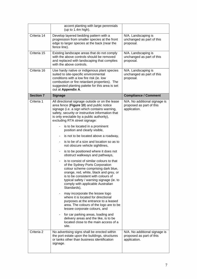
7
accent planting with large perennials (up to 1.4m high).
Criteria 14 Develop layered bedding pattern with a progression from smaller species at the front edge to larger species at the back (near the fence line).
N/A. Landscaping is unchanged as part of this proposal.
Criteria 15 Existing landscape areas that do not comply with the above controls should be removed and replaced with landscaping that complies with the above controls.
N/A. Landscaping is unchanged as part of this proposal.
Criteria 16 Use hardy native or indigenous plant species suited to site-specific environmental conditions with a low fire risk (ie. low combustion or fire retardant properties). The suggested planting palette for this area is set out at Appendix A.
N/A. Landscaping is unchanged as part of this proposal.
Section 7 Signage Compliance / Comment
Criteria 1 All directional signage outside or on the lease area fence (Figure 10) and public notice signage (i.e. a sign which contains warning, safety, security or instructive information that is only erectable by a public authority), excluding RTA street signage:
- is to be located in a prominent position and clearly visible,
- is not to be located above a roadway,
- is to be of a size and location so as to not obscure vehicle sightlines,
- is to be positioned where it does not obstruct walkways and pathways,
- is to consist of similar colours to that of the Sydney Ports Corporation colour scheme comprising dark blue, orange, red, white, black and grey, or is to be consistent with colours of typical safety / warning signage (ie. to comply with applicable Australian Standards),
- may incorporate the lessee logo where it is located for directional purposes at the entrance to a leased area. The colours of the logo are to be lessee corporate colours, and
- for car parking areas, loading and delivery areas and the like, is to be located close to the main access of a site.
N/A. No additional signage is proposed as part of this application.
Criteria 2 No advertising signs shall be erected within the port estate upon the buildings, structures or tanks other than business identification signage.
N/A. No additional signage is proposed as part of this application.

8
Criteria 3 Business identification signage (Figure 11):
- is to be located outside the lease area fence and located on Sydney Ports’ standard Blade Sign,
- should not obscure vehicle sightlines or control signs,
- is permitted on one elevation of the primary building, except where a site has two main road frontages or where there are multiple occupants within a building,
- may comprise text, illustrations, and/or both, to ensure clear identification of the sign and its intent,
- is not to be illuminated or comprise any form of moving or flashing signage,
- is not to occupy more than 10% of any facade or elevation of a building, and
- is to identify visitor entrance points to lease areas.
N/A. No additional signage is proposed as part of this application.
Criteria 4 Business identification signage on the side of tanks is limited to 1 sign per leased area or site (in the case of multiple lease areas being operated as a single site). The sign should be subordinate to the elevation of the tank.
N/A. No additional signage is proposed as part of this application.
Section 8 Lighting Compliance / Comments
Criteria 1 Lighting levels are to be provided in a manner just sufficient to meet operational requirements.
Complies. No additional lighting is required as part of this proposal.
Criteria 2 Lighting levels are to be provided to meet CASA/Air Services requirements.
Complies. No additional lighting is required as part of this proposal.
Criteria 3 Appropriate lighting should be provided at key locations such as pedestrian paths, driveways, parking areas and building entries, so as to identify and provide safe access routes for both employees and visitors.
Complies. No additional lighting is required as part of this proposal.
Criteria 4 Lighting is to be positioned so as to not cause distraction to vehicle drivers on internal or external roads or the occupants of adjoining sites.
Complies. No additional lighting is required as part of this proposal.
Criteria 5 Light spill outside the site boundary and sky lighting is to be avoided through the adoption of measures such as:
- Focussing lights downwards,
- Installing cut-offs or shields on lights,
- Minimising the light mast height, and
- Using low mounting height poles to
Complies. No additional lighting is required as part of this proposal.

9
light non terminal operational areas, including access / egress routes.
Criteria 6 No fixed light is to spill into Penrhyn Estuary or the Estuary flushing channel (Figure 18).
Complies. No additional lighting is required as part of this proposal.
Criteria 7 Low mounting height poles are to be used adjacent to the Estuary.
Complies. No additional lighting is required as part of this proposal.
Criteria 8 Screen moving lights, such as vehicle headlights, so they do not shine into Penrhyn Estuary.
Complies. No additional lighting is required as part of this proposal.
Criteria 9 High level lighting on operational equipment is not to shine into Penrhyn Estuary.
Complies. No additional lighting is required as part of this proposal.
Criteria 10 There is to be a buffer between Penrhyn Estuary and terminal operations to the west of 20m. Road access / egress only is permitted within this area.
N/A. the site is distanced by more than 1000m from the Penrhyn Eastuary.
Section 9 Heritage Compliance / Comments
Criteria 1 The Revetment Wall along Prince of Wales Drive and the Old Government Wharf Remains are listed as heritage items on Sydney Ports’ Section 170 Heritage and Conservation Register (see Figure 12). Any development proposal which has the potential to impact on these items or their heritage significance is to be accompanied by a heritage impact statement.
Complies. The site is located adjacent to the Port Botany Revetment Wall to the south. The proposal will not impact upon the heritage significance of the wall in that the proposed tanks are located wholly within a bunded area of the current site/leased area and setback approximately 80m from the SPC leased boundary.
Criteria 2 Development in the vicinity of a heritage item is to be designed to respect and complement the heritage item.
Complies. The proposed tanks will complement the existing approved development on site and will not alter the significance of the wall.
Section 10 Land Use Safety and Hazard Management Compliance / Comments
Criteria Non Hazardous Facilities
Criteria 1 All proposals for new or expanded non-hazardous developments are required to consider the consequence and risk impacts of existing or proposed potentially hazardous developments on the development proposal. A formal assessment document shall be prepared for the new or expanded non-hazardous development to demonstrate that the development does not result in the proposed facility exceeding the acceptable risk criteria, both individual and societal (refer to the Port Botany Land Use Safety Study Overview Report 1996). A copy of the Risk Assessment, conducted for the proposed development, is to be submitted as part of the
Complies. A FHA is provided with the submission assessing the relevant requirements and criteria.

10
application for development.
Criteria 2 For non-hazardous facilities / sites which intend to become a licensed dangerous goods facility, a Risk Assessment is to be undertaken and is to be submitted as part of the application for development.
N/A.
Specific Criteria
Hazardous Facilities
Criteria 3 All proposals for new or expanded potentially hazardous developments are required to undergo a Risk Assessment. The Risk Assessment is to be submitted as part of the application for development and is to include the implementation, operation and maintenance phases. The assessment is to demonstrate:
- that all foreseeable hazards that may arise from a development, that have a potential to harm the health and safety of any person, the environment, or impact the safety of buildings, equipment, plant and facilities have been clearly identified,
- that there will be limited potential for propagation of hazardous incidents to the neighbouring facilities, in accordance with the “As Low As Reasonably Practicable” (ALARP) principle,
- that the risks associated with the identified hazards at the development have been appropriately analysed and assessed,
- that the proposed development will not contribute to any increase in the cumulative risk (individual & societal risk) beyond the levels shown in Figures 2 and 9 of the Port Botany Land Use Safety Study Overview Report 1996,
- that the assessed risks comply with the relevant risk criteria published by the regulatory authorities,
- that all identified risks will be controlled and minimised by protection and mitigation, and
- that incidents at hazardous facilities will not impact on the use or operation of adjacent land, including Sydney Ports Corporation’s common areas (e.g. roadways). The Risk Assessment for the proposed development is to include the quantitative analysis of incident impacts relating to consequence
Complies. A FHA is provided with the submission assessing the relevant requirements and criteria.
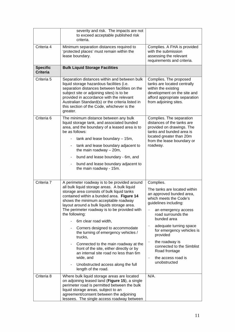
11
severity and risk. The impacts are not to exceed acceptable published risk criteria.
Criteria 4 Minimum separation distances required to ‘protected places’ must remain within the lease boundary.
Complies. A FHA is provided with the submission assessing the relevant requirements and criteria.
Specific Criteria
Bulk Liquid Storage Facilities
Criteria 5 Separation distances within and between bulk liquid storage hazardous facilities (i.e. separation distances between facilities on the subject site or adjoining sites) is to be provided in accordance with the relevant Australian Standard(s) or the criteria listed in this section of the Code, whichever is the greater.
Complies. The proposed tanks are located centrally within the existing development on the site and afford appropriate separation from adjoining sites.
Criteria 6 The minimum distance between any bulk liquid storage tank, and associated bunded area, and the boundary of a leased area is to be as follows:
- tank and lease boundary – 15m,
- tank and lease boundary adjacent to the main roadway – 20m,
- bund and lease boundary - 6m, and
- bund and lease boundary adjacent to the main roadway - 15m.
Complies. The separation distances of the tanks are provided on drawings. The tanks and bunded area is located greater than 20m from the lease boundary or roadway.
Criteria 7 A perimeter roadway is to be provided around all bulk liquid storage areas. A bulk liquid storage area consists of bulk liquid tanks contained within a bunded area. Figure 14 shows the minimum acceptable roadway layout around a bulk liquids storage area. The perimeter roadway is to be provided with the following:
- 6m clear road width,
- Corners designed to accommodate the turning of emergency vehicles / trucks,
- Connected to the main roadway at the front of the site, either directly or by an internal site road no less than 6m wide, and
- Unobstructed access along the full length of the road.
Complies.
The tanks are located within an approved bunded area, which meets the Code’s guidelines including:
- an emergency access road surrounds the bunded area
- adequate turning space for emergency vehicles is provided
- the roadway is connected to the Simblist Road frontage
- the access road is unobstructed
Criteria 8 Where bulk liquid storage areas are located on adjoining leased land (Figure 15), a single perimeter road is permitted between the bulk liquid storage areas, subject to an agreement/consent between the adjoining lessees. The single access roadway between
N/A.

12
the two bulk liquid storage areas is to meet the requirements of criteria 8 above as well as the following:
- any perimeter fence provided between the properties shall be provided with gates at the front and rear sections of the perimeter roadway,
- gates provided for access between the two bulk liquids storage facilities shall have a minimum access opening not less than 5.5m wide, and
- the opening movement of the gates shall not be obstructed by any means other than a conventional locking device, kept and maintained in good repair and working order.
Criteria 9 Where a bulk liquid storage facility operates a road tanker filling area, the road tanker filling area shall be located wholly off any access road that passes the filling area. Figure 16 provides an example of a bulk liquids tanker filling area located adjacent to an access road. The filling area shall be located so that no part of a truck in the filling bay extends into the access road.
Complies. The existing roads tanker facility is proposed to be used for this proposal. It is located off the access road and will not impede the access road.
Specific Criteria
Pipelines
Criteria 10 All pipelines proposed within the Port Botany Port precinct are to be located in the following manner:
- Pipelines required to be installed external to the leased area are to be located within a Port Botany pipeline corridor (Figure 17),
- Exposed above ground level or in an open culvert lined with impermeable material so as to prevent the percolation of any spilled materials through the paving into the underlying sand. The paving and any jointing materials to be used shall be resistant both to heat and the corrosive effects of the range of the products to be transported in the pipeline,
- Underground pipelines are to be avoided unless absolutely necessary,
- Where underground pipelines are used they are to be installed with a leak detection system (e.g. differential flow device, inventory measurement, etc.),
- Underground pipelines are to be suitably protected against corrosion,
Complies.
The proposal includes an extension to the ship to shore 150mm dockline within the leased area of Stage 5, i.e. between the existing areas of the pump bay and tank storage area. There are no external pipelines to the leased area as part of this proposal. All product pipelines are above ground and there are no underground product pipelines as part of this proposal. The existing vapour piping to the existing VEC system for Tank 270 is located below ground between sites with denso wrapping and this will be reused for ethanol vapour venting from Tank 272.

13
considering (but not limited to) the following:
- expected lifetime of the pipeline,
- soil conditions,
- potential acid sulfate soils, and
- water table level.
Details of the leak detection system and corrosion protection are to be provided in the risk assessment documentation.
Criteria 11 All above ground bolted flanged joints, associated with the pipeline outside the main storage bund area, are to be provided with the following:
- A bunded pit to retain any product leaks,
- Protection to prevent leaks from flanges and joints spraying beyond the confines of the pit, and
- Leak detection within the pit and an alarm system to notify of potential flange/joint leaks.
It is noted that the pit may require a cover to prevent the ingress of rain water causing false leak detection alarms.
All above ground product pipework is fully welded, without bolted flanged joints, where located outside containment areas. Bolted flanged joints are located at the pump bay and at the loading/unloading bay. None of these flanges are used routinely as operational activities but infrequently used for maintenance only. Both these bay areas are bunded with wall cover to prevent spraying in three directions and also roof cover. Pumps have double mechanical seals with barrier to alarm and shutdown if either seal has failed so that any losses are minimised. Loading/unloading bay pipework is only online when a person is in attendance to ensure any leaks are immediately detected.
Criteria Areas where petroleum, petroleum products, petro-chemicals and other liquid chemicals are handled or stored
Criteria 12 Areas where Petroleum, Petroleum Products, Petro-Chemicals and other Liquid Chemicals are handled or stored are required to be bunded in accordance with the relevant standards. Where pipeline or hose connections are made or broken for operational activities, these areas are also required to be bunded.
Complies. The proposed tanks will be located within a bunded area of the subject site and meets all legislative requirements.
Criteria 13 The area within all bunded enclosures is to be impervious so as to prevent the percolation of any spilled materials through the paving into the underlying sand. The paving and any jointing materials to be used shall be resistant both to heat and the corrosive effects of the range of the products to be handled or stored.
Complies. The proposed tanks are located within the existing bunded area and meets all legislative requirements.
Criteria 14 The surface of the paving in bunded areas shall be graded so as to permit the flow of
Complies. The proposed tanks are located within the

14
surface water to a suitable drainage system. This surface shall be maintained to prevent ponding.
existing bunded area and meets all legislative requirements.
Criteria 15 All stormwater from bunded areas shall be directed through a separator system located outside the bunded area. The stormwater outlet through the bund walls shall be controlled with a valve located outside the bunded area. This valve shall be kept closed at all times except when stormwater is being released.
Complies. The proposed tanks are located within the existing bunded area and meets all legislative requirements.
Criteria 16 Unbunded areas used for loading of road tankers, refuelling or other handling operations are to have impervious paving so as to prevent the percolation of any spilled materials through the paving into the underlying sand. The paving and any jointing materials to be used shall be resistant both to heat and the corrosive effects of the range of the products to be handled. All drainage from these areas is to be directed to a drainage system via a separator system.
Complies. The area for loading and the like, located at the rear of the site, meets the requirements of the Code.
Section 11 Water Quality and Stormwater Compliance / Comments
Criteria 1 The 1 in 20 year storm event (i.e. 5% Annual Exceedance Probability (AEP)) is to be accommodated within a piped stormwater system.
Complies. The existing stormwater system can accommodate a 1 in 20 year storm event.
Criteria 2 The design and layout of leased areas, including the siting of buildings and the positioning of bunded areas and container stacks, is to take into consideration the need to provide unobstructed stormwater overland flow paths.
Complies. The proposal does not alter the overall site arrangement and layout is not changed through the construction of the 2 tanks.
Criteria 3 The first flush from impervious areas is to be captured and treated to prevent pollutants from entering Botany Bay. Pollutants to be removed must include sediments, litter, rubbish, oils, greases and other hydrocarbons.
Complies. Impervious areas will be treated to ensure pollutants do not leave the site.
Criteria 4 First flush stormwater (treated or otherwise) is not permitted to be discharged to Penrhyn Estuary or the Estuary flushing channel (Figure 18).
Complies. The proposal will apply the current stormwater management practices to the subject area and will not discharge to the Penrhyn estuary and are distinctly separate.
Criteria 5 Stormwater leaving the site is not to create erosion within Penrhyn Estuary.
Complies. The proposal will apply the current stormwater management practices to the subject area and will not create erosion of the estuary.
Criteria 6 Measures to contain spills and prevent them from discharging through the stormwater system are to be identified and spill response
Complies. The proposal will apply the current stormwater management practices to the

15
procedures documented. subject area.
Criteria 7 Emergency spill kits are to be available on-site and staff are to be trained in how to use them.
Complies. Staff are currently trained in appropriate emergency procedures. Spill procedures are noted in Section 3.4.2 of the REF.
Section 12 Air Quality Compliance / Comments
Criteria 1 Site areas which are trafficked by vehicles and trucks are, as a minimum, to be sealed to minimise dust generation.
Complies. Areas trafficked by vehicles are sealed.
Criteria 2 Information regarding the products to be stored and/or handled on the premises is to be provided as well as the proposed storage area for such products. Products handled on site which have an offensive odour are to be handled in a closed circuit or sealed system.
Complies. The storage and handling of products is appropriately handled in accordance with the Code.
Criteria 3 Vehicles, plant and equipment are to be maintained and operated in good working condition and are to be turned off when not in use to minimise emissions to air.
Complies. All equipment on site is appropriately maintained to minimise air emissions.
Criteria 4 Building materials that may potentially contribute to poor internal air quality, such as those generating formaldehyde or those that may create a breathing hazard in the case of fire (e.g. polyurethane), are to be avoided.
N/A.
Criteria 5 Air filters are to be installed in all ventilation systems to remove particulate contamination.
N/A. No new ventilation systems are proposed.
Criteria 6 All development is to incorporate measures to minimise emissions that adversely impact on local air quality.
Complies. Commentary on air quality is contained in Section 6.5.3 of the REF.
Criteria 7 Any emissions of smoke, dust, particulate matter, steam or gas must meet Civil Aviation Safety Authority (CASA) / Air Services Australia (ASA) requirements.
Complies. Commentary on air quality is contained in Section 6.5.3 of the REF.
Section 13 Bird Management Compliance / Comments
Criteria 1 An assessment of aspects of the proposed development which could attract bird species that may pose a hazard to airport operations is to be provided as part of the application for development. The assessment is to include any mitigation measures to be implemented. Aspects to be considered include potential for roosting on roofs, lights poles, site areas having low levels of activity, areas where water may pond, etc.
Complies. Existing measures for bird management will be applied to the two new tanks, where applicable.
Criteria 2 Height restrictions in Figure 1 are required to be complied with unless a shorebird impact assessment is undertaken which confirms that there is no adverse impact on shorebird access or use of Penrhyn Estuary.
Complies. The height of the tanks complies with the Code.
Criteria 3 No terminal operations (except for road access / egress) are permitted within 20m of
Complies. The proposed works are within the lease area and are greater than

16
the western edge of Penrhyn Estuary. 20m from the estuary.
Criteria 4 Container stacks, buildings and tanks are to be set back at least 100m from the western edge of Penrhyn Estuary and 64m from the southern edge of Penrhyn Estuary.
Complies. The proposed works are within the leased area of the site and are greater than 100m from the estuary.
Section 14 Noise and Vibration Compliance / Comments
Criteria 1 For all new developments, proponents are to identify:
- relevant noise criteria based on the DECC guidelines,
- all sources of noise,
- noise emission levels, and
- proposed mitigation measures.
Complies. The proposal will comply with all relevant guidelines. Section 6.5.4 of the REF details the acoustic impact of the proposal.
Criteria 2 All buildings, equipment and operational processes are to be selected or designed to minimise the emission of noise.
Complies. The proposal will meet all operational noise goals and no mitigation measures were determined to be required.
Criteria 3 Noise reduction measures for mobile equipment, trucks, other vehicles and machinery are to be implemented, such as through insulation, alternative reversing alarms and ‘engine off’ policies.
Complies. The proposal will meet all operational noise goals through appropriate on site management of machinery and trucks.
Criteria 4 Noisy plant and equipment should be located as far as possible from noise sensitive areas, optimising attenuation effects from topography, natural and purpose built barriers.
Complies. No proposed changes to the location of plant and equipment.
Criteria 5 Within three (3) months of completion of the development the applicant is to provide evidence to Sydney Ports of compliance with the relevant noise criteria for the development.
Noted.
Criteria 6 Vibration transmitted outside the site during operations must be within acceptable limits based on DECC guidelines.
Complies. All relevant guidelines can be complied with.
Section 15 Soil Contamination Compliance / Comments
Criteria 1 For all development a soil and groundwater contamination assessment is to be undertaken as part of the application for development. Where a contamination hazard is deemed possible, approved mitigation / remediation measures are to be undertaken. This is to be generally in accordance with the DECC’s Guidelines for Consultants Reporting on Contaminated Sites.
Complies. The extent of site excavation is anticipated to be less than 300mm for the tank bases and accordingly the extent of soil disturbance is minimal. Section 6.5.2 provides comment on potential soil impacts.

17
Section 16 Groundwater Management Zone (Elgas Deed)
Compliance / Comments
Criteria 1 The Groundwater Management Zone (GMZ) associated with the Elgas LPG Storage Cavern is illustrated at Figure 19. Any development within the area marked ‘GMZ(B)’ is required to comply with the ‘Groundwater Management Zone Deed’ between the Water Administration Ministerial Corporation, Sydney Port Corporation, Elgas Limited and the Marine Ministerial Holding Corporation (NSW Maritime). A copy of the Deed is available on request from Sydney Ports Corporation
Complies. The proposal will comply with the Groundwater Management Zone Deed as the site is located in GMZ(B).


APPENDICES
Appendix C Green Port Guidelines Checklist


Sydney Ports Corporation Green Port Guidelines checklist 1
Applicant details
Name Geoff Millard Company Terminals Pty Limited
Address 45 Friendship Road, Port Botany
City/Town Matraville State NSW Postcode 2036
Telephone 02 9316 1922 Mobile 0418440239 Email [email protected]
Project details
Location of proposed development
9-11 Simblist road , Port Botany , Lot 622687
Description of proposed development
Installation of two 1,750 m3 tanks for Ethanol and Petrol or Bulk Liquids, associated pipe work, pumps and loading equipment
The details on this form are the provisions and intentions for maximising the environmental sustainability of this development.
Name Geoff Millard
Signature Date 20th November 2009

Sydney Ports Corporation Green Port Guidelines checklist 2
Item No
Purpose/criteria Has this been addressed? (Yes, No, N/A)
How has it been addressed? Or, why has it not been addressed?
Provide details of supporting documentation/ reference material
R1 Reduce the quantity of new materials being used by reusing materials or by utilising recycled materials.
Yes The new tanks will use the existing bund structure that is already in place, without having to build new structure
Soil / rock that is excavated for building and plant construction will be re-used in the formation of the earthen bund wall.
See site layout drawings, R.E.F
R2 Encourage environmentally friendly production of materials.
Yes New build requiring new steel for fabrication of tanks and pipe work – no alternative available
See site layout drawings
R3 Specify materials that have minimal embodied energy and environmental impact.
Yes Making use of locally sourced earthen / clay fill where necessary (lower embodied energy than new concrete construct)
Materials selection
R4 Consider the end of life of materials and the whole building, design for deconstruction.
Yes Steel used in the construction of the tanks and pipelines is suitable for recycling at the end of life.
All pipe work is suitable for recycling at end of life cycle
Extension to pump bay 5 is also constructed of steel and colour bond steel which is suitable for recycling at end of economic life.
N/A

Sydney Ports Corporation Green Port Guidelines checklist 3
Item No
Purpose/criteria Has this been addressed? (Yes, No, N/A)
How has it been addressed? Or, why has it not been addressed?
Provide details of supporting documentation/ reference material
W1 Minimise the generation of wastes.
Yes Storage tanks are designed with internal stripping lines and sumps to minimise waste generation. Docklines have pigging systems to completely empty them so as to prevent waste generation. Dry Break couplings will be used in the truck fill bay to reduce spillage, leaks and waste.
One storage tank has internal floating roofs plus road tanker loading operates with a VRU to recover petrol/ethanol waste & minimise waste discharging to atmosphere.
All water, essentially rain water, that is collected from the road ways and tank farms is processed via API oil separator , which separates any residual hydrocarbons and clean water is discharged to Botany Bay. Any contaminated water is minimised in this way and stored prior to disposal in an authorized waste treatment facility.
The Site has an environmental management manual which is accredited to the ISO 14001 environmental management standard. The environmental manual will include all waste generating activities & their impacts plus control measures though its Environmental Aspects Register.
Terminals Environmental Management Manual
W2 Facilitate recycling to reduce the amount of waste going to landfill.
Yes Minimal wastes are generated in the facility.
Any residual water in the petrol storage tanks will be checked so that hydrocarbon layer is recycled back to tank and removed water only is treated via the API separator to eliminate hydrocarbons.
Waste m
anagement
W3 Ensure the safe storage and handling of hazardous wastes.
Yes Terminals P/L operates under an Environmental Management Manual which is accredited to ISO 14001 environmental standard and have a DECC (EPA) storage licence number 1048. In addition Terminals has approvals to store Dangerous Goods from WorkCover under DG
Terminals Environmental and Health & Safety policies and Environmental Management Manual
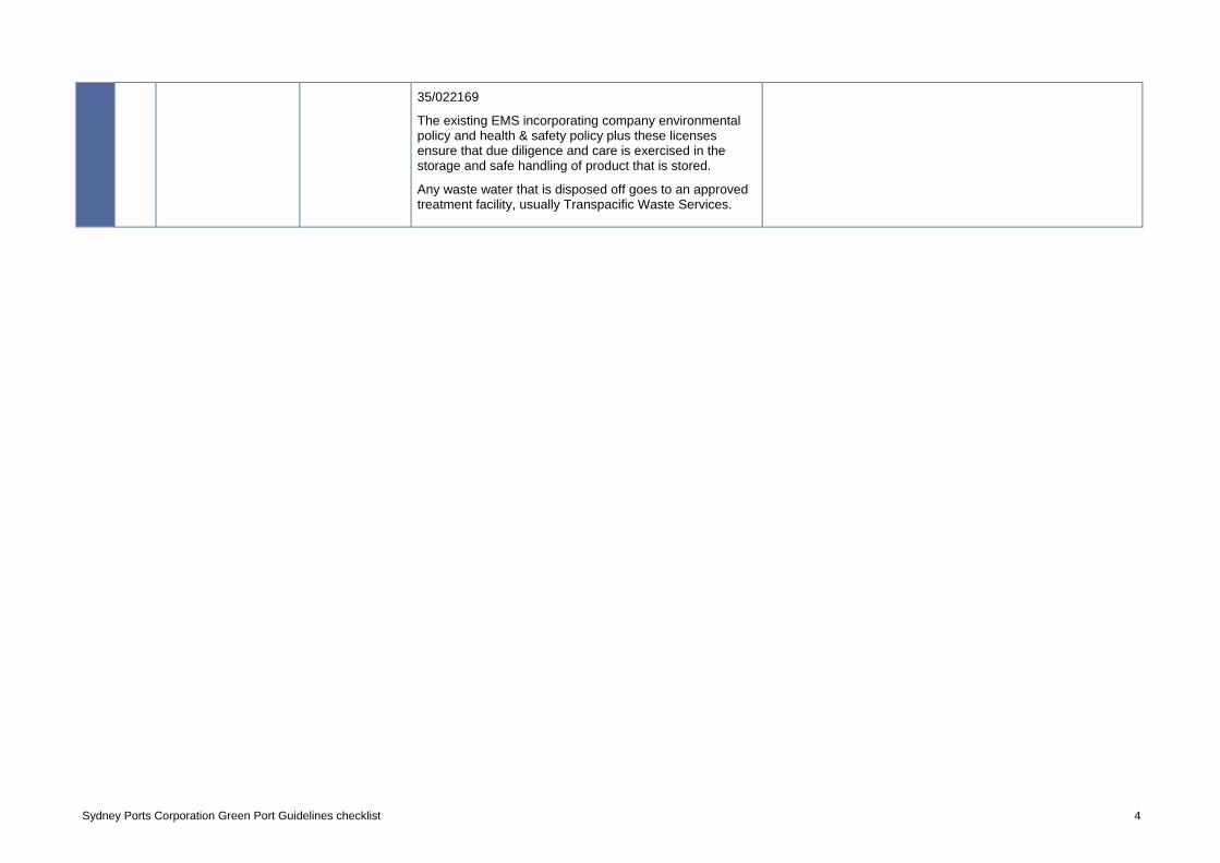
Sydney Ports Corporation Green Port Guidelines checklist 4
35/022169
The existing EMS incorporating company environmental policy and health & safety policy plus these licenses ensure that due diligence and care is exercised in the storage and safe handling of product that is stored.
Any waste water that is disposed off goes to an approved treatment facility, usually Transpacific Waste Services.

Sydney Ports Corporation Green Port Guidelines checklist 5
Item No
Purpose/criteria Has this been addressed? (Yes, No, N/A)
How has it been addressed? Or, why has it not been addressed?
Provide details of supporting documentation/ reference material
H1 Reduce consumption of potable water internally.
N/A No water is consumed in normal operating conditions in the proposed expansion.
The only time water is used is during cleaning of the storage tanks. This is expected to occur approx every 10 years.
AS 1940, storage & handling of flammable & combustible liquids.
H2 Manage and monitor water usage and any leaks.
N/A As above
H3 Reduce the quantity of potable water used for landscape irrigation.
N/A No water will be used to irrigate for landscape or nature strips. Any plantings where required will use mulch to reduce water losses.
Water consum
ption H4 Treat water on-site and reuse the treated water to reduce demand on the local potable water supply and the demand on the local infrastructure.
Yes As above water treatment is confined to oil / water separator that ensures that water discharged to Botany Bay does not contain Hydrocarbons

Sydney Ports Corporation Green Port Guidelines checklist 6
Item No
Purpose/criteria Has this been addressed? (Yes, No, N/A)
How has it been addressed? Or, why has it not been addressed?
Provide details of supporting documentation/ reference material
E1 Reduce energy consumption and hence greenhouse gas emissions.
Yes The loading gantry and broadcast lighting in the stage V area has photo electric cells connected that result in lighting only being active when natural lighting is low.
The office building in the stage V area has timed duration lighting and as a result will turn off after approx 3 minutes.
Pump systems are automatic on need basis only (ie not continuous) and optimised to use energy efficient motors to reduce energy consumption.
E2 Manage the use of energy to minimise consumption.
N/A As above.
E3 Source energy from renewable sources.
N/A Electrical energy is the source for these site operations.
Energy use
E4 Source energy from alternate energy sources and use less greenhouse intensive fuels (in particular limit diesel use).
N/A As above; no diesel usage envisaged.

Sydney Ports Corporation Green Port Guidelines checklist 7
Item No
Purpose/criteria Has this been addressed? (Yes, No, N/A)
How has it been addressed? Or, why has it not been addressed?
Provide details of supporting documentation/ reference material
T1 Encourage the use of alternative modes of transport by employees, in order to reduce the amount of inefficient/individual car travel and therefore greenhouse gas emissions.
N/A The majority of employees work outside hours of applicable public transport and have to come into work for shipping at unusual hours.
Port Botany is not particularly well serviced with public transport
Transportation
T2 Reduce greenhouse gas emissions from operational vehicles and equipment.
N/A For operations; only vehicles used on the existing site are two forklifts and two trucks, which operate on Diesel fuel. These could be used at the proposal site but this would be very infrequently.

Sydney Ports Corporation Green Port Guidelines checklist 8
Item No
Purpose/criteria Has this been addressed? (Yes, No, N/A)
How has it been addressed? Or, why has it not been addressed?
Provide details of supporting documentation/ reference material
IE1 Improve the quality of indoor air to protect the health of employees and enhance productivity.
N/A No new buildings being constructed as part of this project
IE2 Optimise daylighting and make best use of artificial lighting to assist eye health and productivity.
N/a As above
Indoor environment IE3 Provide optimum
acoustical environment for productivity and to prevent ear damage.
N/A As Above

Sydney Ports Corporation Green Port Guidelines checklist 9
Item No
Purpose/criteria Has this been addressed? (Yes, No, N/A)
How has it been addressed? Or, why has it not been addressed?
Provide details of supporting documentation/ reference material
EM1 Protect the ozone layer and reduce the potential for global warming.
N/A No new air conditioners or similar equipment is being installed as part of this project
Storage tanks have internal floating roof or connected to vapour emission control system and tanker loading is treated by a vapour recovery unit to reduce potential waste emissions to the atmosphere.
EM2 Limit the generation of air pollutants and ensure that they are emitted away from sensitive receptors.
Yes During the construction phase if high levels of dust is generated then appropriate water sprays will be used to minimise dust and particulate carry. Vehicles to park in designated areas during construction.
The area is 1200 metres away from residential areas.
EM3 Minimise odours. Yes A Vapour Recovery unit will be installed to recover Hydrocarbon vapours from the Truck filling area. This is a high efficiency unit that recovers the vapours and returns them to the appropriate storage tank.
EM4 Minimise noise nuisance.
Yes Noise from construction has been considered in the assessment. Levels are not expected to be high and sensitive receptors are more than 1 km away.
Em
issions
EM5 Avoid light spill into night sky or neighbouring properties/areas.
N/A

Sydney Ports Corporation Green Port Guidelines checklist 10
EM6 Avoid accidental contact with hazardous or poisonous goods.
Yes Individual contractors will have set storage areas and a construction safety study will be conducted prior to the commencement of construction to address these aspects.

Sydney Ports Corporation Green Port Guidelines checklist 11
Item No
Purpose/criteria Has this been addressed? (Yes, No, N/A)
How has it been addressed? Or, why has it not been addressed?
Provide details of supporting documentation/ reference material
HQ1 Manage stormwater to reduce peak stormwater flows and protect water quality.
Yes Products are stored in approved storage tanks built to API650 construction code and housed in suitable bunded areas as required by the legislation
Storm water run off from driveways is directed through a first flush pit, designed for high rainfall events, before leaving the site to prevent initial poor water quality run off.
Storm water is collected in the storage bund areas. Checked for contamination and if none then transferred to the API Oil / water separator pit whereupon clean water is transferred to Botany Bay. Samples are taken and this process is managed.
Contaminated water is transferred to the waste water collection tanks and then disposed of to an EPA approved treatment facility.
Spill kit is also provided in the truck loading bay and collection pit in the same area.
Environmental Management Manual.
HQ2 Manage water quality to protect the harbour and other water bodies.
As Above
Spill kits provided in truck loading area.
Water quality is checked before discharge.
Water quality
HQ3 Prevent damage from potential flood events and water table changes.
N/A Area is not prone to flooding and water table is 3 to 4 metres below this area.
First flush pit has been designed for storm rainfall events.

Sydney Ports Corporation Green Port Guidelines checklist 12
Item No
Purpose/criteria Has this been addressed? (Yes, No, N/A)
How has it been addressed? Or, why has it not been addressed?
Provide details of supporting documentation/ reference material
L1 Encourage the redevelopment of sites that have previously been developed and remediate contaminated land.
N/A No contaminated land.
L2 Use landscaping to enhance biodiversity and conserve and create habitat for flora and fauna.
N/A No landscaping is planned in the development
L3 Enhance visual amenity.
N/A As above
Final storage tanks will blend in with existing storage tanks & infrastructure.
Land use
L4 Avoid impact on identified heritage items.
N/A There are no identified heritage areas on the proposed construction area.

Sydney Ports Corporation Green Port Guidelines checklist 13
Item No
Purpose/criteria Has this been addressed? (Yes, No, N/A)
How has it been addressed? Or, why has it not been addressed?
Provide details of supporting documentation/ reference material
M1 Maintain good relationships with stakeholders and respond to any complaints.
Yes Terminals is a member of local community/industrial neighbour groups like BEREPA and Port Botany Neighbourhood Liaison Group. Consultation with these groups is planned for their next meetings.
Environment Management Manual includes a public complaints procedure.
R.E.F
M2 Provide a framework for identifying, managing and minimising environmental impacts, and maximising environmental benefits.
Yes Terminals P/L has a comprehensive Environmental management Manual in place which is available for perusal. This will be updated to include construction & operation activities for this project.
Terminals P/L is accredited to the ISO14001 Environmental management standard
Terminals P/L has all applicable Dangerous Goods, warehouse and DECC licenses
Environmental Management Manual
Cert No 0402898/B
EPA L 1048, DG 35/022169
Environm
ental managem
ent M3 Educate developers, tenants and employees about ESD and how to improve sustainability.
Yes Terminals P/L participates in the sustainable Ports program that has recently been initiated by SPC and supports the initiatives & programs that will flow from it.
No new buildings in proposal – therefore no building guide or training for occupants is required.


APPENDICES
SA3870-REFv1 Page 35
Appendix D Final Hazard Analysis


REVISED FINAL HAZARD ANALYSIS,
STAGE 5 EXPANSION MODIFICATIONS,
TANKS 271 AND 272,
TERMINALS PTY LTD, PORT BOTANY, NSW
Prepared by: Dean Shewring
5 December 2009
Pinnacle Risk Management Pty LimitedABN 83 098 666 703
PO Box 5024 Elanora HeightsNSW Australia 2101
Telephone: (02) 9913 7284Facsimile: (02) 9913 7930

Pinnacle Risk Management
App D - Terminals Stage 5 2009 FHA Report Rev B 5 December 2009
Disclaimer This report was prepared by Pinnacle Risk Management Pty Limited (Pinnacle Risk Management) as an account of work for Terminals Pty Ltd (Terminals). The material in it reflects Pinnacle Risk Management’s best judgement in the light of the information available to it at the time of preparation. However, as Pinnacle Risk Management cannot control the conditions under which this report may be used, Pinnacle Risk Management will not be responsible for damages of any nature resulting from use of or reliance upon this report. Pinnacle Risk Management’s responsibility for advice given is subject to the terms of engagement with Terminals.
Revised Final Hazard Analysis, Terminals Pty Ltd,
Stage 5 Modifications - Tanks 271 and 272
Rev Date Description Reviewed By
A 25/11/09 Draft for Comment Terminals
B 5/12/09 Draft Comments Included Terminals

Pinnacle Risk Management
App D - Terminals Stage 5 2009 FHA Report Rev B 5 December 2009
CONTENTS CONTENTS ............................................................................................................ I
CONTENTS ............................................................................................................II
EXECUTIVE SUMMARY............................................................................................ I
GLOSSARY........................................................................................................... III
1 INTRODUCTION .............................................................................................. 1
1.1 Background ..................................................................................... 1
1.2 Objectives ........................................................................................ 2
1.3 Scope................................................................................................ 2
1.4 Methodology .................................................................................... 3
1.5 Findings and Recommendations ................................................... 4
2 SITE DESCRIPTION......................................................................................... 6
3 DESCRIPTION OF THE 2009 SITE CHANGES ................................................... 10
3.1 Proposed Tanks............................................................................. 10
3.2 Extra Bund Capacity ..................................................................... 11
3.3 Piping ............................................................................................. 11
3.4 Stage 5 Road Tanker Loading / Unloading Bay .......................... 11
3.5 Ethanol Road Tanker Unloading .................................................. 13
3.6 Road Tanker Loading Control System ........................................ 13
3.7 Vapour Recovery Unit (VRU) ........................................................ 13
3.8 Fire Prevention and Control ......................................................... 14
3.9 Product Rates ................................................................................ 14
4 HAZARD IDENTIFICATION.............................................................................. 15
4.1 Hazardous Materials...................................................................... 15
4.2 Potential Hazardous Incidents Review ........................................ 15
4.3 Hazardous Events - Shipping....................................................... 16

Pinnacle Risk Management
App D - Terminals Stage 5 2009 FHA Report Rev B 5 December 2009
4.4 Hazardous Events – Terminal Operations................................... 18
4.5 Safety Management Systems ....................................................... 24
4.5.1 Safety Software in Risk Assessment ............................................... 24
5 RISK ANALYSIS ........................................................................................... 26
5.1 Pool Fire Modelling ....................................................................... 28
5.2 Products of Combustion............................................................... 34
5.3 Vapour Explosions ........................................................................ 35
5.4 Aircraft Impact and Other External Events ................................. 37
5.5 Cumulative Risk............................................................................. 39
5.6 Risk from Neighbouring Container Storage................................ 39
5.7 Societal Risk .................................................................................. 40
5.8 Risk to the Biophysical Environment .......................................... 40
5.8.1 Escape of Materials to Atmosphere................................................. 41
5.8.2 Escape of Materials to Soil or Waterways ....................................... 41
5.8.3 Solid Wastes ................................................................................... 42
6 CONCLUSION AND RECOMMENDATIONS......................................................... 43
7 REFERENCES .............................................................................................. 45
LIST OF FIGURES 1 ........................................................................................................................... Figure 1 - Site Location ........................................................................................ 7
2 ........................................................................................................................... Figure 2 – Site Layout .......................................................................................... 9

Pinnacle Risk Management
App D - Terminals Stage 5 2009 FHA Report Rev B 5 December 2009
LIST OF TABLES 3 ........................................................................................................................... Table 1 – Total Site Product Throughputs .......................................................... 14
4 ........................................................................................................................... Table 2 – Transfer Options................................................................................. 14
5 ........................................................................................................................... Table 3 – Hazard Identification Word Diagram................................................... 19
6 ........................................................................................................................... Table 4 - Risk Criteria, New Plants..................................................................... 27
7 ........................................................................................................................... Table 5 – Predicted SEP .................................................................................... 29
8 ........................................................................................................................... Table 6 – Fire Scenarios Calculation Data and Results ..................................... 30
9 ........................................................................................................................... Table 7 - Radiant Heat Impact............................................................................ 32
10 ......................................................................................................................... Table 8 – Layout Considerations – Tolerable Radiant Heat Levels .................... 33
11 ......................................................................................................................... Table 9 – Fire Plume Rise Modelling.................................................................. 35
12 ......................................................................................................................... Table 10 – Aircraft Crash Data for Sydney Airport.............................................. 37
LIST OF APPENDICES 13 ......................................................................................................................... Appendix 1 – Drawings.
14 ......................................................................................................................... Appendix 2 – Radiant Heat Contours.

Pinnacle Risk Management
App D - Terminals Stage 5 2009 FHA Report Rev B 5 December 2009 i
EXECUTIVE SUMMARY Terminals Pty Ltd (Terminals) is proposing to increase the storage capacity at the Port Botany facility. The main feature of the expansion project will be the addition of two new tanks (each 1,750 m3) for the storage of premium unleaded petrol (PULP) and ethanol. These tanks will be located within the existing bunded area that was installed for the approved Stage 5 expansion project in 1997.
As part of the project requirements, a revised, Stage 5 Final Hazard Analysis (FHA) is required. This report details the results from the analysis.
The risks associated with the proposed new tanks and the associated equipment at the Terminals site, Port Botany, have been assessed and compared against the DoP risk criteria.
In summary:
1. Fires:
No risk of injury or fatality at residential areas or other sensitive land uses as the separation distance is large, i.e. 1 km or larger to residential areas;
As the estimated radiant heat levels from potential fire events are approximately 12.6 kW/m2 or lower at neighbouring industrial facilities, the likelihood of fatality at these locations is acceptably low and there exists a high probability of escape; and
There are no fire events which have the potential to cause propagation at neighbouring industrial facilities.
2. Vapour explosions:
These are considered rare events for these types of facilities and materials, and hence the risk of injury, fatality and/or propagation at residential areas or other sensitive land uses (i.e. more than 1 km away) or at neighbouring facilities is not considered intolerable.
3. There are no significant changes to the risk profiles with respect to shipping or road transport associated with this project when compared to the 1997 approved project (as the proposed quantities are only approximately 3% higher).
4. Societal risk is qualitatively concluded to be acceptable given:
Few events analysed in the study have the potential for off-site impact and, for the ones that do, their likelihood is acceptably low; and
The population density in the Port Botany area is relatively low.

Pinnacle Risk Management
App D - Terminals Stage 5 2009 FHA Report Rev B 5 December 2009 ii
Therefore, the results of this revised FHA show that the risks associated with the proposed changes comply with the DoP guidelines for tolerable fatality, injury, irritation, propagation and societal risk. Also, transport risk and risks to the biophysical environment from potential hazardous events are broadly acceptable.
Additionally, the two proposed tanks to the stage 5 area have no significant impact to the cumulative individual risk contours (for future development planning) as presented in the Port Botany Land Use Safety Study by DUAP in 1996.
The primary reason for the low risk levels from proposed changes is that significant consequential impacts from potential hazardous events (mainly radiant heat from fires) do not extend far from the relevant processing areas.
It is assumed that the proposed changes will be reviewed via the HAZOP methodology, a fire safety study will be performed and the existing safety management systems and emergency response plans will be updated to reflect the proposed changes.
The following recommendation is made from this review:
1. The new tank level instrumentation should be adequately assessed for reliability (e.g. AS 61511, Functional Safety – Safety Instrumented Systems for the Process Industry Sector).

Pinnacle Risk Management
App D - Terminals Stage 5 2009 FHA Report Rev B 5 December 2009 iii
GLOSSARY ACARRE Australian Centre for Advanced Risk and Reliability Engineering
API American Petroleum Institute
AS Australian Standard
ASME American Society for Mechanical Engineers
BLB Bulk Liquids Berth
CCTV Closed circuit television
CS Carbon steel
DECC Department of Environment and Climate Change
DoP NSW Department of Planning
EIS Environmental Impact Statement
ESD Emergency shutdown
FHA Final hazard analysis
HAZAN Hazard analysis
HAZOP Hazard and operability study
HDPE High density polyethylene
HIPAP Hazardous Industry Planning Advisory Paper
LEL Lower explosion limit
LPG Liquefied petroleum gas
LNG Liquefied natural gas
NOx Nitrous oxides
PHA Preliminary hazard analysis
PMPY Per million per year
PPE Personnel protective equipment
PULP Premium unleaded petrol
QRA Quantitative risk assessment
ROV Remotely operated valves

Pinnacle Risk Management
App D - Terminals Stage 5 2009 FHA Report Rev B 5 December 2009 iv
ROSOV Remotely operated shut-off valves
SEP Surface emissive power
SPC Sydney Ports Corporation
TPL Terminals Pty Ltd
UEL Upper explosive limit
ULP Unleaded petrol
VIE Vacuum insulated expander
VRU Vapour recovery unit
WW Waste water

Pinnacle Risk Management
App D - Terminals Stage 5 2009 FHA Report Rev B 5 December 2009 1
REPORT
1 INTRODUCTION
1.1 BACKGROUND
Terminals Pty Ltd (Terminals) is proposing to increase the storage capacity at the Port Botany facility. The main feature of the expansion project will be the addition of two new tanks (each 1,750 m3) for the storage of premium unleaded petrol (PULP) and ethanol. These tanks will be located within the existing bunded area that was installed for the approved Stage 5 expansion project in 1997.
This 1997 approved project was the last of the five major expansion projects the company has undertaken at this site. The Stage 5 expansion project initially proposed the installation of approximately 12 tanks and associated equipment. However, only one tank was originally installed (Tank 270) with a new road tanker unloading / loadout facility.
In 2008, Terminals sought and gained approval for the installation of two new larger tanks in the Stage 5 area. These tanks are yet to be installed. Each tank will be 10,000 m3 and are designed to store unleaded petrol (ULP). An updated FHA was prepared and approved for the installation of these two tanks (Ref 1).
As business conditions have changed again, the proposed changes to the Stage 5 area are now the two new smaller tanks (1,750 m3) and associated piping systems. Therefore, the proposal is to have the following tanks in the Stage 5 area:
Tank 270 (original 5,000 m3 tank - approved);
Tanks 273 and 274 (10,000 m3 tanks - approved); and
Tanks 271 and 272 (1,750 m3 tanks – subject to approval).
In addition to the two new smaller tanks and their associated piping, other site changes include:
Road tanker loading systems upgrades to allow ethanol blends to be made;
Extending an existing ship to shore 250 mm dockline to Stage 5A for unloading PULP and any other products from ships;
Installing a new road tanker unloading pump at the existing truck loading / unloading bay for unloading ethanol from road tankers;

Pinnacle Risk Management
App D - Terminals Stage 5 2009 FHA Report Rev B 5 December 2009 2
New transfer pumps (to the existing Stage 5 road tanker loadout pump bay);
Existing bund capacity redesign; and
New fire protection systems.
As part of the project requirements, a revised Final Hazard Analysis (FHA) is required. This revised FHA has been prepared in accordance with the guidelines published by the NSW Department of Planning (DoP) Hazardous Industry Planning Advisory Paper (HIPAP) No 6 (Ref 2). Terminals have appointed Pinnacle Risk Management Pty Ltd (Pinnacle Risk Management) to prepare this Final Hazard Analysis report.
As a revised FHA was prepared for the two larger tanks in 2008 (Ref 1) then this analysis is an updated of the 2008 revised FHA report, i.e. all five Stage 5 tanks are included.
1.2 OBJECTIVES
The main aims of this revised FHA study are to:
Identify the credible, potential hazardous events associated with the existing and proposed Stage 5 expansion equipment;
Evaluate the level of risk associated with the identified potential hazardous events to surrounding land users, including other Port Botany companies and their operations, and compare the calculated risk levels with the risk criteria published by the DoP in HIPAP No 4 (Ref 3);
Review the adequacy of the proposed safeguards to prevent and mitigate the potential hazardous events; and
Where necessary, submit recommendations to Terminals to ensure that the proposed modifications are operated and maintained at acceptable levels of safety and effective safety management systems are used.
1.3 SCOPE
This revised FHA assesses the credible, potential hazardous events and corresponding risks associated with the Stage 5 equipment at the Terminals Port Botany facility.
In summary, the assessment includes:
The two new smaller tanks (271 and 272) as well as the existing tank 270 (currently used to store diesel) and the yet to be installed tanks 273 and 274 (proposed to store ULP);
On-site pipelines (existing lines in the pipeline corridor from the Bulk Liquids Berth (BLB) will be used);

Pinnacle Risk Management
App D - Terminals Stage 5 2009 FHA Report Rev B 5 December 2009 3
The associated product transfer pumps;
The existing Stage 5 road tanker loading bay that will be used for product export / import; and
The new vapour recovery unit required for the installation of tanks 273 and 274.
Off-site transport risk is not included in this revised FHA as the total quantity being distributed via road tankers is only slightly more than the quantity approved in 1997 (see Section 3). Also, as the planned increase in shipping quantity is again only slightly more than the 1997 approved value (see Section 3), shipping and pipeline corridor risks are not reviewed in detail in this report.
For completeness, however, qualitative assessment of the use of marine hoses and shipping activities is included in this report. The BLB is a purpose built wharf specifically for transferring hazardous cargo such as the materials stored at Port Botany and it is used by a number of companies. Hoses and marine loading arms are currently used without unacceptable levels of risk.
1.4 METHODOLOGY
In accordance with the approach recommended by the DoP in HIPAP 6 (Ref 2) the underlying methodology of the revised FHA is risk-based, that is, the risk of a particular potentially hazardous event is assessed as the outcome of its consequences and likelihood.
The revised FHA has been conducted as follows:
Initially, the Stage 5 equipment and its location were reviewed to identify credible, potential hazardous events, their causes and consequences. Proposed safeguards were also included in this review;
As the equipment is located at a significant distance from other land users and the changes to the site are relatively moderate (the site already has 65 tanks), the consequences of each potential hazardous event were estimated to determine if there is any possible unacceptable off-site impacts;
Included in the analysis is the risk of propagation between the Stage 5 equipment and the existing equipment (both onsite and off-site);
Where adverse off-site impacts can occur, the likelihood of each potential hazardous event was reviewed, using appropriate techniques / methods, to check if there is any significant increase to existing risk levels and if the risk levels are within the criteria in HIPAP 4 (Ref 3); and
A comparison is made to the existing Port Botany regional study (Ref 4) to determine if there is any impact on cumulative risk.

Pinnacle Risk Management
App D - Terminals Stage 5 2009 FHA Report Rev B 5 December 2009 4
1.5 FINDINGS AND RECOMMENDATIONS
The risks associated with the proposed new tanks and the associated equipment at the Terminals site, Port Botany, have been assessed and compared against the DoP risk criteria.
In summary:
1. Fires:
No risk of injury or fatality at residential areas or other sensitive land uses as the separation distance is large, i.e. 1 km or larger to residential areas;
As the estimated radiant heat levels from potential fire events are approximately 12.6 kW/m2 or lower at neighbouring industrial facilities, the likelihood of fatality at these locations is acceptably low and there exists a high probability of escape; and
There are no fire events which have the potential to cause propagation at neighbouring industrial facilities.
2. Vapour explosions:
These are considered rare events for these types of facilities and materials, and hence the risk of injury, fatality and/or propagation at residential areas or other sensitive land uses (i.e. more than 1 km away) or at neighbouring facilities is not considered intolerable.
3. There are no significant changes to the risk profiles with respect to shipping or road transport associated with this project when compared to the 1997 approved project (as the proposed quantities are only approximately 3% higher).
4. Societal risk is qualitatively concluded to be acceptable given:
Few events analysed in the study have the potential for off-site impact and, for the ones that do, their likelihood is acceptably low; and
The population density in the Port Botany area is relatively low.
Therefore, the results of this revised FHA show that the risks associated with the proposed changes comply with the DoP guidelines for tolerable fatality, injury, irritation, propagation and societal risk. Also, transport risk and risks to the biophysical environment from potential hazardous events are broadly acceptable.
Additionally, the two proposed tanks to the stage 5 area have no significant impact to the cumulative individual risk contours (for future development planning) as presented in the Port Botany Land Use Safety Study by DUAP in 1996.
Pinnacle Risk Management
App D - Terminals Stage 5 2009 FHA Report Rev B 5 December 2009 5
The primary reason for the low risk levels from proposed changes is that significant consequential impacts from potential hazardous events (mainly radiant heat from fires) do not extend far from the relevant processing areas.
It is assumed that the proposed changes will be reviewed via the HAZOP methodology, a fire safety study will be performed and the existing safety management systems and emergency response plans will be updated to reflect the proposed changes.
The following recommendation is made from this review:
1. The new tank level instrumentation should be adequately assessed for reliability (e.g. AS 61511, Functional Safety – Safety Instrumented Systems for the Process Industry Sector).

Pinnacle Risk Management
App D - Terminals Stage 5 2009 FHA Report Rev B 5 December 2009 6
2 SITE DESCRIPTION
The proposed expansion is to be located on the Terminals leased land at 45 Friendship Road, Port Botany. The land is part of the Port Botany reclamation area owned by the Sydney Ports Corporation (SPC) and is devoted to port and associated activities. The nearest residents are over 1 kilometre away. See Figure 1 for details of the site location.
Port Botany is one of the major ports in New South Wales with trade including petroleum products, liquefied petroleum gas (LPG), and liquid chemicals. The majority of industries in the Port Botany industrial region are involved in the storage and distribution of these products and are located on Friendship Road in the vicinity of the site. These industries include:
Hydrocarbons: The terminal imports and stores LPG, propane and butane for transport by pipeline to Botany Industrial Park manufacturing site at Botany.
Vopak (Sites A and B): These terminals store and distribute products similar to those at Terminals Pty Ltd.
Origin Energy: The site imports LPG by sea tankers and stores it for distribution by road tankers.
Elgas Pty Ltd: An underground storage cavern and above-ground facilities for storing and distributing LPG.
P&O Ports, Molineaux Point: A facility for storing and distributing shipping containers.
Construction of the Terminals site began in 1978 and has expanded in five major stages to date. The terminal has 65 tanks of various sizes with a total storage capacity of 53,000 m3 of bulk liquids ranging from animal fats, vegetable oils, industrial chemicals, petrochemicals and petroleum products. These products are handled into and out of the terminal by:
Sea-going parcel tankers from the Bulk Liquids Berth at the end of Charlotte Road;
Road tankers;
Drums;
Pipeline from the Orica petrochemical complex at Botany; and
Iso-tank containers.
The dangerous goods stored at the site are Classes 3, 6, 8 and 9. Combustibles (C1 and C2) are also stored in bulk. Liquid nitrogen is stored in a small VIE for tank blanketing etc.

Pinnacle Risk Management
App D - Terminals Stage 5 2009 FHA Report Rev B 5 December 2009 7
Figure 1 - Site Location

Pinnacle Risk Management
App D - Terminals Stage 5 2009 FHA Report Rev B 5 December 2009 8
The site layout, including the proposed new smaller tanks, is shown in Figure 2.
Security of the site is achieved by a number of means. This includes site personnel and security patrols by an external security company (this includes weekends and night patrols). The site normally operates 5 days per week (day shift only, depending on whether a ship is in or not). Also, the site is fully fenced (adequate construction) and non-operating gates are locked (e.g. to the pipeline corridor). The main entrance and exit gates are normally closed. A security swipe card is required to open them. Security cameras (CCTV) are installed for staff to view visitors and site activities.
There are approximately 20 people on site (plus drivers, visitors etc) during normal working hours.
Depending on weather conditions, the site may lie under the flight path to /from Sydney Airport. There are no known natural hazards associated with this location that pose unacceptable levels of risk.

Pinnacle Risk Management
App D - Terminals Stage 5 2009 FHA Report Rev B 5 December 2009 9
Figure 2 – Site Layout

Pinnacle Risk Management
App D - Terminals Stage 5 2009 FHA Report Rev B 5 December 2009 10
3 DESCRIPTION OF THE 2009 SITE CHANGES
The 2009 proposed changes to the site are described as follows. The previous site changes were described in Ref 1 and are not reiterated here.
3.1 PROPOSED TANKS
As mentioned previously, it is proposed to construct two additional storage tanks within the Stage 5 area of the site; each with a capacity of 1,750m³. The tanks are to be 11.8 metres in diameter and 17.0 metres high. These two tanks will be used to store ethanol and premium unleaded petrol (at ambient temperature) and will also be suitable for the storage of diesel fuel and jet fuel.
The PULP tank (T271) will have a primary steel roof as well as an internal floating roof in order to minimise vapour emissions. It will be fitted with water sprays and foam injection. A level gauge and high level instruments will be installed to reduce the risk of tank overfilling.
The Ethanol tank (T272) will have a fixed roof fitted with nitrogen blanketing in the headspace. It will be connected to the existing vapour emission control system (VECS) and it will also be fitted with water sprays and foam injection. A level gauge and high level instruments will also be installed to reduce the risk of tank overfilling.
Protection systems on the two storage tanks will include:
Procedures for liquid transfers, stormwater management, regular maintenance and inspection;
Fully welded and tested carbon steel plate construction;
Remote emergency shutdown valves on the liquid outlet lines with non-return valves on the inlet lines;
An internal floating roof for the petrol tank and connection to vapour emission control system for the ethanol tank to minimise air emissions as per industry good practice standards;
Fire management plan and radiation protection systems for potential adjacent tank on fire scenarios;
Structural integrity tests conducted every 10 years in accordance with AS1940;
Non-return valves in pipelines at the bulk liquids berth, tanks and for unloading operations to prevent backflow;
Containment of liquid within proposed extra capacity bund;

Pinnacle Risk Management
App D - Terminals Stage 5 2009 FHA Report Rev B 5 December 2009 11
Tank foundations will have an impervious membrane with ‘tell-tale’ drains installed for leak detection of the tank base,
High level and redundant high high level alarm system; and
Emergency alarms.
3.2 EXTRA BUND CAPACITY
In response to AS1940, which requires a bund to be able to contain the contents of the largest tank as well as an appropriate amount of rainwater, an extra capacity bund is already part of the modified approval for stage V. This will be marginally increased to accommodate the two extra tanks. It is proposed to locate this bund to the east of the existing bund wall.
The bunded area will have a sump for the collection of rainwater and possible spills. Water collected in the sump will be sampled (e.g. ethanol is soluble in water) and inspected prior to release. Should the water be contaminated, it will be collected and transported to an approved (DECC) waste treatment facility. If the water is not contaminated, it will be released to stormwater via an oil / water separator by opening a manual valve.
3.3 PIPING
It is anticipated that PULP would come into the Terminal via an existing dockline (150 mm) from the Bulk Liquids Berth (BLB). This line will be extended within the Stage 5 area for the PULP to flow to Tank 271. It is proposed to run this new piping above ground to pump bay number 5.
In addition, pipework and blending facilities will be installed in the existing Stage 5 loading / unloading bay to enable petrol / ethanol blends to be loaded into trucks for subsequent distribution.
A small diaphragm pump will be provided for the PULP tank dewatering system.
There are no anticipated piping changes at the Bulk Liquids Berth.
3.4 STAGE 5 ROAD TANKER LOADING / UNLOADING BAY
The operation of the site will not deviate from the current approval in place.
The loading of fuels is essentially a ‘self service’ arrangement but with appropriate safeguards, training, accreditation and management practices.
When the driver enters the site via Simblist Road (through the use of a key card) an electric access card starts a timer that limits the time the driver has on site. If this time is exceeded the security monitoring company will investigate the cause of delay. Loading interlock systems are in place to ensure that the driver connects up to the vapour discharge, earth bonding connection and compartment overfill protection before loading can commence. Automatic

Pinnacle Risk Management
App D - Terminals Stage 5 2009 FHA Report Rev B 5 December 2009 12
bottom loading is via purpose built tanker loading arms and trucks will load at a rate of up to 2,400 litres per minute into each truck compartment.
There are a number of protection features already in operation at the loading / unloading bay including:
Procedures for operations, operator training, maintenance, training of maintenance employees, contractor safety training and emergencies;
Specific driver training in loading and unloading operations, liquid transfers and stormwater management;
Requirement that the driver must be present during loading operations;
Local Emergency Stop stations have been installed that initiate pump shutdowns and tank / loading isolations;
Facilities to contain spills or contaminated rainwater and to return this material to the existing liquid effluent tank and/or alternative storage tank;
Fire water hose points;
Foam supplies for foam attachment points;
Foam and dry powder fire extinguishers;
Road tanker loading operations to be provided with an automatic foam deluge protection (as proposed in Ref 1);
Loading ceases if the air line breaks as the actuated valves fail closed on loss of air;
Spillage containment of tanker compartment contents in the event of a spill;
Continuous closed circuit television monitoring in place;
Safety air brakes on the wheels to ensure that the truck cannot leave with the loading hose attached (i.e. road tanker driveaway);
Truck electric’s isolations switch;
Scully system lead designed to dissipate any static electricity build up and to prevent an overflow condition by shutting down the loading system upon detecting a high level in any compartment;
Additional high level detection in the vapour knock out pot that shuts down the loading system;
Dead-man recognition requiring the driver to press the key pad every 2.5 minutes to verify that loading is continuing safely;

Pinnacle Risk Management
App D - Terminals Stage 5 2009 FHA Report Rev B 5 December 2009 13
Dry brake couplings to avoid leaks and spills while connecting and disconnecting hoses;
Detonation arrester located as close to the truck vapour hose connection point as practical to reduce the possibility of a flame flash back to/from the road tanker;
Recovery of displaced vapours from the truck head space in the vapour recovery unit (VRU) and return of resulting liquid back to the appropriate storage tank; and
A first-flush and separator pit designed for spill containment.
For safety reasons, no queuing of trucks is permitted within the site.
3.5 ETHANOL ROAD TANKER UNLOADING
Ethanol is anticipated to arrive via road tankers from local ethanol manufacturers. Some ethanol could also be imported from the Bulk Liquids Berth using the existing 150 mm docklines that extended within the stage 5 area to Tank 272.
To transfer the ethanol from the road tanker, a new road tanker unloading pump is to be installed at the existing Stage 5 truck loading / unloading bay. Ethanol will be pumped directly to Tank 272 for subsequent use for blending (i.e. road tanker filling at the same Stage 5 loading / unloading bay).
3.6 ROAD TANKER LOADING CONTROL SYSTEM
The existing Contrec road tanker loading system is to be upgraded to accommodate the required blending (i.e. a 10% ethanol / PULP blend). All road tanker loading / blending operations (driver only loading) will be controlled by the existing Contrec pre scheduled loading system. Tank 271 and 272 ROV’s (remotely operated valves) and transfer pumps will be controlled via the Contrec loading system and linked into the ESD (emergency shutdown) systems.
New pumps to deliver PULP and ethanol to the road tankers will be installed in the existing Stage 5 pump bay. Road tanker loading is to be via a new bottom loading arm at the existing No. 5 road tanker loading bay. The hours of operation for PULP / ethanol road tanker loading will be the same as existing, i.e. 24/7 driver only loading.
3.7 VAPOUR RECOVERY UNIT (VRU)
A vapour recovery unit is to be located near the existing Stage 5 truck loading bay as per the pre-approved 2008 expansion plan. Road tankers being filled with ethanol blends will also be connected to this VRU for vapour recovery during road tanker filling.

Pinnacle Risk Management
App D - Terminals Stage 5 2009 FHA Report Rev B 5 December 2009 14
3.8 FIRE PREVENTION AND CONTROL
Fire protection for the two proposed storage tanks is via two diesel operated fire water pumps in the existing site with 1,400m³ of water in storage and continuous replenishment from the Sydney Water reticulation system. The existing foam supply is adequate to supply the two new tanks and piping will be installed to deliver this foam. If the foam and fire water systems are activated an alarm is raised to the NSW Fire Brigade.
3.9 PRODUCT RATES
When the project is complete, the total site product thoughputs are envisaged to be (Table 1):
Table 1 – Total Site Product Throughputs
Product Throughputs
Original DA After Expansion
Ships per year 58 60
Road tankers (trucks per day)
40 41
Hence, the total throughputs are approximately 3% higher than the already approved shipping and road tanker values.
A number of transfers into, out of and within the additional tanks are possible. The possible transfers and their transfer rates are outlined in Table 2:
Table 2 – Transfer Options
Transfer Product Pump Design Flow Rate
Ship Unloading to T271
PULP Ships pumps 650m3/hr
T271 to Road Tanker Loading
PULP 1 x Duty 126m3/hr
T272 to Road Tanker Loading
Ethanol 1 x Duty 40m3/hr
Road Tanker Unloading to T272
Ethanol 1 x Duty 53m3/hr
Notes:
The ship unloading operation will be identical to the current practice with the addition of an independent level alarm high high fitted to the PULP tank which will alarm to alert personnel via intrinsically safe mobile radios.
Double mechanical seals with low nitrogen barrier gas flow alarms will be installed for the PULP and ethanol transfer pumps.

Pinnacle Risk Management
App D - Terminals Stage 5 2009 FHA Report Rev B 5 December 2009 15
4 HAZARD IDENTIFICATION
4.1 HAZARDOUS MATERIALS
The combined stage 5 equipment will handle and store the following chemicals:
1. ULP (unleaded petrol) and PULP (premium unleaded petrol);
2. Ethanol; and
3. Diesel / biodiesel.
The site has a current licence for the storage of these materials and hence no new material hazards will be introduced as part of this project. A summary of the material hazards is given below.
ULP, PULP and ethanol are Class 3 flammable liquids. Ethanol is soluble in water (ULP / PULP are not).
Ethanol’s flammability limits are LEL 3.5% and UEL 19%. The control measures regarding safe handling and storage of ethanol are similar to Class 3 materials, e.g. elimination of ignition sources, including static. It burns with a near colourless flame. The vapour is heavier than air and can accumulate in low points. Explosions of confined vapours are possible. Ethanol combustion produces carbon dioxide and carbon monoxide. Fires are normally extinguished with alcohol resistant foam.
Diesel, including biodiesel, is classified as a combustible liquid, C1.
All petroleum products are potentially injurious to humans, e.g. carcinogenic properties, and aquatic organisms.
4.2 POTENTIAL HAZARDOUS INCIDENTS REVIEW
In accordance with the requirements of Guidelines for Hazard Analysis, (Ref 2), it is necessary to identify hazardous events associated with the tank operations. As recommended in HIPAP 6, the FHA focuses on “atypical and abnormal events and conditions. It is not intended to apply to continuous or normal operating emissions to air or water”.
A search of available literature and information was conducted to review the types of historical events that can occur with bulk fuel terminals. The search included the following references:
1. Frank Lees, Loss Prevention in the Process Industries (Ref 5);
2. Australian, US and UK Departments of Transport records;
3. US National Transport Safety Board statistics;

Pinnacle Risk Management
App D - Terminals Stage 5 2009 FHA Report Rev B 5 December 2009 16
4. US Occupational Health and Safety Administration statistics;
5. US Chemical Safety and Hazard Investigation Board statistics;
6. UK Health and Safety Executive statistics; and
7. Previous risk studies for terminals.
A review of larger reported tank fire incidents worldwide has been carried out (Ref 6). It was found that there have been no serious injury or fatality incidents to surrounding land users in advanced countries (characterised by modern technology, knowledgeable management and good emergency services) in the past 30 years.
4.3 HAZARDOUS EVENTS - SHIPPING
Whilst it is not the purpose of this revised FHA to perform a detailed analysis of all shipping activities at or near the BLB, the following types of potential hazardous events are included for information. As previously noted in Section 1.3, the BLB is a purpose built wharf specifically for transferring hazardous cargo such as the materials stored at Port Botany and it is used by a number of companies. The proposed changes to Terminals operations are commensurate with the design intent of the BLB.
Hazardous events resulting from the release of the products include pool fires upon ignition and pollution of the local environment.
Shipping incidents which could occur that may lead to losses of containment of products include grounding, collision (ship-ship), impacts with the wharf and movement away from the wharf during transfer.
Descriptions of potential scenarios are as follows (Refs 5 and 7).
Grounding
Grounding occurs when a vessel runs onto the shore or submerged rocks and would require either loss of power and/or steering, human error or severe weather conditions.
Striking
This is where a vessel moored at the wharf is struck by another passing vessel. The risk of significant damage to the moored vessel in such an event clearly depends on the size, speed, direction and type of the vessel doing the impacting.
Collision
Collision refers to the collision of two vessels underway, either with their own power or being manoeuvred by tugs. The potential energy in such a collision

Pinnacle Risk Management
App D - Terminals Stage 5 2009 FHA Report Rev B 5 December 2009 17
may theoretically be sufficient to damage the outer and inner (if included) hulls of a vessel.
Impact with Wharf
Impact with the wharf / jetty could result from the vessel approaching the wharf too fast or attempting to dock during bad weather.
Fire / Explosion
A fire or explosion (e.g. within the engine room) on a vessel may spread to involve the cargo and/or bunker. A fire / explosion could also occur directly within the cargo.
Transfer Incidents
Losses of containment can occur while a vessel is being loaded / unloaded. Causes include water hammer from, for example, fast closing of valves, movement of the ship away from the wharf, line failures due to mechanical impact from a vehicle, corrosion, mechanical defect (e.g. poor weld), flange leaks and thermal expansion of trapped liquid causing overpressure, hose or hose coupling failures, and human error, e.g. leaving drain valves open. Overflowing of the vessel’s tanks can also occur during loading.
In addition to the above events, the following events are also possible but are generally found to represent lower risks:
Foundering / Capsize
This occurs when a ship sinks in rough weather or a leak has occurred.
Structural Failure
This occurs where the cargo tank cracks due to fatigue, wave loads, vibration or adverse cargo load distribution.
Aircraft Strike
There exists the possibility of an aircraft or helicopter impact with the ship.
Spontaneous Failure
Manufacturing defects may lead to a spontaneous failure of the cargo tank.
Domino Incident
Where an accident on one ship either causes or is caused by an accident on a nearby ship or in a storage or process plant onshore.

Pinnacle Risk Management
App D - Terminals Stage 5 2009 FHA Report Rev B 5 December 2009 18
Sabotage / Terrorism
It is possible that an act of sabotage, either from company or non-company employees or terrorism can lead to a loss of containment.
Natural Events
Natural events such as strong winds can lead to losses of containment.
Other Causes
Other causes that can lead to hazardous events include liquid sloshing in a cargo tank and overpressurisation of a cargo tank.
The accident outcomes for the above causes for a loss of containment of products could be a fire (pool fire) and/or environmental effect, including fish and bird kill. These events can also lead to injuries due to radiant heat impact and/or equipment damage. Explosions and/or fires will also release products of combustion such as carbon dioxide, carbon monoxide, water vapour, NOx, soot etc. These potential hazardous events can occur now at the BLB or immediate area. There are no new potential hazardous events at the BLB as a result of the increased use of hoses.
4.4 HAZARDOUS EVENTS – TERMINAL OPERATIONS
In keeping with the principles of risk assessments, credible, hazardous events with the potential for off-site effects have been identified. That is, “slips, trips and falls” type events are not included nor are non credible situations such as an aircraft crash occurring at the same time as an earthquake. The large majority of the specific release scenarios are generic equipment failures, e.g. failures of tanks, pipes etc, from previous industrial incidents. These are supplemented by process incidents due to other abnormal modes of operation, control system failure and human error.
The credible, significant incidents identified for all new major equipment items are summarised in the Hazard Identification Word Diagram following (Table 3). The diagram presents the causes and consequences of the events, together with major preventative and protective features that are included as part of the design.

Pinnacle Risk Management
App D - Terminals Stage 5 2009 FHA Report Rev B 5 December 2009 19
Table 3 – Hazard Identification Word Diagram
Event ID No.
Hazardous Event Causes Possible Consequences Proposed Prevention and Mitigation Control Measures
1. Major mechanical failure of tanks
Metal fatigue Faulty fabrication Corrosion of tank base / weld Tank explosion due to lightning strike / breach of hazardous area ignition source controls Adjacent tank on fire Blocked vent
Large spillage of flammable or combustible materials in bund. Fire if ignited For historical tank explosions, some tanks have rocketed away from the foundations Impact to people (radiant heat and/or exposure to products), property and the environment (products of combustion)
Tanks designed to API 650 Regular maintenance and inspection procedures Tank and site fire protection facilities available Explosions only occur when ullage vapour is between LEL and UEL. Tank 271 has a floating roof and Tank 272 will be nitrogen padded to minimise the potential for a flammable atmosphere to be created. Design conforms to AS1940 requirements
2. Tank roof failure (Tank 271)
Flammable atmosphere in tank roof space (ignition by lightning / breach of hazardous area ignition source controls) Vents blocked during filling procedure High speed filling
Rim seal fire (floating roof tank) Initial explosion possible leading to a tank top fire Potential for spill into the bund with a fire if ignition occurs Boil over possible if water layer exists Impact to people (radiant heat and/or exposure to products), property and the environment (products of combustion)
Internal floating roof with mechanical shoe seal Foam injection system Fire fighting system Regular maintenance and inspection procedures Level alarms, controlled tank filling Explosions prevention as per Item 1

Pinnacle Risk Management
App D - Terminals Stage 5 2009 FHA Report Rev B 5 December 2009 20
Event ID No.
Hazardous Event Causes Possible Consequences Proposed Prevention and Mitigation Control Measures
3. Pipe failure (i.e. new piping within the terminal)
Corrosion Impact Maintenance work Pressure surge
Spillage of flammable or combustible material. Fire if ignited. Impact to people (radiant heat and/or exposure to products), property and the environment (products of combustion)
Regular maintenance and inspection procedures Emergency isolation valves on the new tanks Fire fighting system (including foam) Pipes sometimes in bunded areas Pipelines surge study The piping is designed to ASME 31.3 / AS 4041 to resist the combined effects on internal pressure due to contents, wind loads, earthquake forces and hydrostatic test loads
4. Pipeline failure external to the terminal – note that this is existing piping
As per 3 above plus vandalism
As per 3 above Regular maintenance and inspection procedures Emergency isolation valves Fire fighting system (including foam) Pipelines surge study Routine inspections during transfers

Pinnacle Risk Management
App D - Terminals Stage 5 2009 FHA Report Rev B 5 December 2009 21
Event ID No.
Hazardous Event Causes Possible Consequences Proposed Prevention and Mitigation Control Measures
5. Spillage of flammable or combustible material to the bunds
Tank overfilled during transfer Tank drain valve left open or tank sampling valve left open, e.g. human error
Spill into bund Bund fire if ignited Possible tank fire and boil over Impact to people (radiant heat and/or exposure to products), property and the environment (products of combustion) If not ignited, potential for off-site contamination as ethanol is soluble in water
Fire fighting as above Two independent level devices installed Emergency shutdown system Operating procedures Sampling and inspection procedures prior to disposing of waste bund water
6. Leak during filling of road tanker
Failure of loading arm Leak from valves or fittings Road tanker overfill
Leak of petroleum product in loading area Fire if ignited Impact to people (radiant heat and/or exposure to products), property and the environment (products of combustion)
High level of surveillance and use of leak detection & shutdown systems Drivers are well trained so as to minimise chance of operator error & ensure quick response to leaks Road tanker bay to be fitted with automatic foam deluge system Ignition sources controlled Scully truck overfill shutdown system and vent knock out pot level shutdown system

Pinnacle Risk Management
App D - Terminals Stage 5 2009 FHA Report Rev B 5 December 2009 22
Event ID No.
Hazardous Event Causes Possible Consequences Proposed Prevention and Mitigation Control Measures
7. Road tanker drive-away incident (i.e. driver does not disconnect the hose and drives away from the loading bay)
Failure of procedures and hardware interlocks
Leak of petroleum product in loading area Fire if ignited Impact to people (radiant heat and/or exposure to products), property and the environment (products of combustion) Ignition source present (road tanker engine), hence fire more likely
Driver training Driver not in cab during filling Brakes interlocked prior to connection and until disconnection Road tanker bays to be fitted with automatic foam deluge system "Dry-break" hose couplings
8. Leak at product pumps
Pump seal, shaft or casing failures
Leak of petroleum product in loading area Fire if ignited Impact to people (radiant heat and/or exposure to products), property and the environment (products of combustion)
Double mechanical seal with seal failure trip interlock Condition monitoring and preventative maintenance of pumps Fire fighting as above Pumps in contained area
9. Leak at vapour recovery unit
Failure of vessel due to corrosion or other cause
Potential for fires and environmental impact Regular maintenance and inspection procedures Gas detection system and alarm Stoppage of road tanker filling Fixed firewater monitors for fighting fires

Pinnacle Risk Management
App D - Terminals Stage 5 2009 FHA Report Rev B 5 December 2009 23
Event ID No.
Hazardous Event Causes Possible Consequences Proposed Prevention and Mitigation Control Measures
10. Road accident (off-site)
Bad road or traffic conditions
Most likely outcome is no loss of load Leak may occur, leading to fire Impact to people (radiant heat and/or exposure to products), property and the environment (products of combustion)
Design of road tankers to survive accident without a loss of containment - pipes and running gear designed to shear off without product loss Driver training and choice of routes to reduce accident potential
11. Aircraft crash Pilot error Bad weather Plane fault
Propagation to tank / bund fires Impact to people (radiant heat and/or exposure to products), property and the environment (products of combustion)
As per aviation standards
12. CStrong winds, earthquakes
Strong winds cause equipment damage etc
Loss of containment leading to a fire if ignited (as above)
The tanks are designed API 650 / AS 1692 / AS 1170 to resist the combined effects on internal pressure due to contents, weight of platforms, ladders, live loads, wind loads, earthquake forces and hydrostatic test loads Operations stopped in adverse weather conditions
13. Breach of Security / Sabotage
Disgruntled employee or intruder
Possible release of product with consequences as per above
Security measures include fencing, CCTV, security patrols, operator / driver vigilance Pressure tests prior to commissioning transfer Pipe inspections prior to commissioning transfer; regularly during ship discharge and otherwise on a periodic basis

Pinnacle Risk Management
App D - Terminals Stage 5 2009 FHA Report Rev B 5 December 2009 24
4.5 SAFETY MANAGEMENT SYSTEMS
Safety management systems are intended to minimise the risk from potentially hazardous installations by a combination of hardware (i.e. design) and software factors (managements systems such as procedures, policies, plans, training etc). To ensure safe operation of the terminal, both the hardware and the software systems must be of high standard.
Terminals personnel, being employed by a company specialising in the storage and distribution of Dangerous Goods, are well aware of the hazardous nature of materials associated with the project scope. However, it is acknowledged that the proposed terminal modifications will necessitate changes to the existing safety management system.
Terminals’ operations and safety management systems at Port Botany have been previously reviewed during hazard audits by Pinnacle Risk Management (Refs 8, 9 and 10). These hazard audits have found that the safety management systems in use at the time of the audits are generally adequate for the nature of the hazards present. It is expected that modification of the existing safety management system to accommodate the proposed changes should present little difficulty.
Emergency Response
An audible alarm alerts plant operators if an emergency occurs. Emergency procedures exist for the site and are routinely tested via simulated emergencies. This includes joint Port Botany exercises.
4.5.1 Safety Software in Risk Assessment
In risk assessments, incidents are assessed in terms of consequences and frequencies, leading to a measure of risk. Where possible, frequency data comes from actual experience. However, in many cases, the frequencies used are generic, based on historical information from a variety of plants and processes with different standards and designs.
The quality of the management systems (known as "safety software") in place in these historical plants will vary. Some will have little or no software, such as work permits and modification procedures, in place. Others will have exemplary systems covering all issues of safe operation. Clearly, the generic frequencies derived from a wide sample represent the failure rates of an "average plant". This hypothetical average plant would have average hardware and software safety systems in place.
If an installation with below average safety software is assessed using generic frequencies, it is likely that risk will be underestimated. Conversely, if a plant is above average, the risk will probably be overestimated. However, it is extremely difficult to quantify the effect of software on plant safety.

Pinnacle Risk Management
App D - Terminals Stage 5 2009 FHA Report Rev B 5 December 2009 25
Therefore, Pinnacle Risk Management adopts a policy which does not attempt to quantitatively account for the presence of and quality of software safety systems. It is assumed that the generic failure frequencies used apply to installations which have safety software corresponding to accepted industry practice. It is believed that this assumption will be conservative in that it will overstate the risk from well managed installations such as the Terminals’ site. Therefore, any quantitative approach is valid (i.e. conservative) only if safety management within the operation being assessed is of a high standard.

Pinnacle Risk Management
App D - Terminals Stage 5 2009 FHA Report Rev B 5 December 2009 26
5 RISK ANALYSIS
The assessment of risks to both the public as well as to operating personnel around this industrial development requires the application of the basic steps outlined in Section 1. As per HIPAP 6 (Ref 2), the chosen analysis technique should be commensurate with the nature of the risks involved.
The typical risk analysis methodology attempts to take account of all credible hazardous situations that may arise from the operation of processing plants etc. For quantitative risk analysis (QRA), this is done by first taking a probabilistic approach to vessel and pipe failures for all vessels containing hazardous materials. Specific incidents, identified by a variety of techniques, are then added and the combined data used to generate composite risk contours which can be used for both the public and plant personnel.
Having assembled data on possible incidents, risk analysis requires the following general approach for individual incidents (which are then summated for all potential recognised incidents to get cumulative risk):
Risk = Likelihood x Consequence
For QRA and hazard analysis, the consequences of an incident are calculated using standard correlations and probit-type methods which assess the effect of fire radiation, explosion overpressure and toxicity to an individual, depending on the type of hazard.
In this revised FHA, however, the approach adopted to assess the risk of the identified hazardous events is scenario based risk assessment. The reasons for this approach are:
1. The distance to residential and other sensitive land users is large for the Port Botany area and hence it is unlikely that any significant consequential impacts, e.g. due to radiant heat from fires, from the Stage 5 equipment will have any significant contribution to off-site risk; and
2. The distance between the on-site tanks and other equipment to the neighbouring industrial facilities is relatively large, hence, the consequential impacts may not have any significant contribution to off-site industrial risk.
Therefore, appropriate analysis of credible scenarios is performed in this revised FHA. Initially, the consequences of the potential events with off-site impact are assessed. For the events which do not contribute to off-site risk (as determined by the risk criteria in HIPAP No. 4 (Ref 3) then no further risk analysis is warranted. When the consequence of an event does contribute to off-site, the likelihood and hence risk is then analysed as required.

Pinnacle Risk Management
App D - Terminals Stage 5 2009 FHA Report Rev B 5 December 2009 27
The risk criteria applying to developments in NSW are summarised in Table 4 below (from Ref 3).
Table 4 - Risk Criteria, New Plants
Description Risk Criteria
Fatality risk to sensitive uses, including hospitals, schools, aged care 0.5 x 10⁻⁶ per year
Fatality risk to residential and hotels 1 x 10⁻⁶ per year
Fatality risk to commercial areas, including offices, retail centres, warehouses
5 x 10⁻⁶ per year
Fatality risk to sporting complexes and active open spaces 10 x 10-6 per year
Fatality risk to contained within the boundary of an industrial site 50 x 10-6 per year
Injury risk – incident heat flux radiation at residential areas should not exceed 4.7 kW/m2 at frequencies of more than 50 chances in a million per year or incident explosion overpressure at residential areas should not exceed 7 kPa at frequencies of more than 50 chances in a million per year
50 x 10-6 per year
Toxic exposure - Toxic concentrations in residential areas which would be seriously injurious to sensitive members of the community following a relatively short period of exposure
10 x 10-6 per year
Toxic exposure - Toxic concentrations in residential areas which should cause irritation to eyes or throat, coughing or other acute physiological responses in sensitive members of the community
50 x 10-6 per year
Propagation due to Fire and Explosion – exceed radiant heat levels of 23 kW/m2 or explosion overpressures of 14 kPa in adjacent industrial facilities
50 x 10-6 per year
As discussed above, the consequences of the potential hazardous events are initially analysed to determine if any events have the potential to contribute to the above-listed criteria and hence worthy of further analysis.

Pinnacle Risk Management
App D - Terminals Stage 5 2009 FHA Report Rev B 5 December 2009 28
5.1 POOL FIRE MODELLING
The credible hazardous events associated with the terminal operations are largely pool fires due to potential losses of containment being ignited. The potential fire events associated with all the Stage 5 area tanks and bund are detailed in Table 6 (all events are included for cumulative risk assessment purposes). This data is used in the fire modelling. A discussion on burndown rates and surface emissive powers is given below.
Burndown Rates:
For burning liquid pools (Ref 11), heat is transferred to the liquid via conduction, radiation and from the pool rim. For pool fires less than 1 m diameter, the radiative heat transfer and the resulting burning rate increases with pool diameter. For pool diameters greater than 1 m, radiative heat transfer dominates, thus a constant burning rate is expected.
Wind can affect the burning rate (experiments have shown both an increase and decrease in burning rates due to the effects wind) but also can affect flame stability (and hence average flame emissive power) (Ref 12). Therefore, average reported values for burndown rates are used in this study.
For very large pool fires with diameters greater than 5 to 10 m, there is some evidence of a slight decrease in burning rate. This is believed to be due to poor mixing with air and is unlikely to reduce the burning rate by more than 20%.
Typical burndown rates for petrol and diesel are 4 to 6 mm/min (Refs 5 and 13). Therefore, an average value of 5 mm/min is taken as the fire scenarios typically involve large diameters for these materials. The burndown rate for ethanol is taken to be 1 mm/min (Ref 5).
The burning rate is used in the determination of flame height. Normally, the higher the burning rate, the higher the estimated flame height.
Surface Emissive Power:
Surface emissive power can be either derived by calculation or by experimentation. Unfortunately, experimental values for surface emissive powers are limited.
When calculated, the results can be overly conservative, particularly for large diameter fires, as it is assumed that the entire flame is at the same surface emissive power. This is not the case for large diameter fires as air entrainment to the centre of the flame is limited and hence inefficient combustion occurs.
A surface emissive power correlation that fits experimental data well for products that produce smokey flames (as is the case for petrol and diesel in tanks 270, 271, 273 and 274) is as follows (Ref 11):
SEP (average) = 140 x e (-0.12xD) + 20 x (1 – e (-0.12xD))

Pinnacle Risk Management
App D - Terminals Stage 5 2009 FHA Report Rev B 5 December 2009 29
Where D = the pool fire diameter.
The constant, 140 kW/m2, is the maximum emissive power of luminous spots and the constant, 20 kW/m2, is the emissive power of smoke.
The values in the following table are derived from this equation.
Table 5 – Predicted SEP
Diameter, m SEP Average, kW/m2
1 126
5 86
10 56
15 40
20 31
25 26
30 23
35 22
40 21
45 21
50 20
Note that materials such as propane, ethane, LNG, ethanol and other low molecular weight materials do not produce sooty flames. For ethanol, a literature search indicates there are limited published experimental surface emissive powers, in particular, for large diameter pools. Therefore, the predicted method from TNO (Ref 12) was chosen, i.e.:
SEP (ethanol) = Fs x M x Hc / (1 + (4 x FH / D)) Where: Fs = Fraction of heat radiated from the surface of the flames
(maximum of 0.35 – conservatively used for ethanol) M = Burning rate, kg/m2/s (0.015 kg/m2/s for ethanol, Ref 12) Hc = Heat of combustion, kJ/kg (30,630 kJ/kg for ethanol) FH = Flame height, m (Thomas equation used, Refs 5 and 12) D = Pool diameter, m
The distances to specified radiant heat levels for the potential fire scenarios are shown in Table 6. The distances were calculated using the View Factor model for pool fires (Refs 5 and 13). This model was used as it better approximates the square / rectangular shapes of the potential bund fires. It will be slightly conservative for the tank top fires. Graphical representations of the estimated radiant heat contours are shown in Appendix 2.

Pinnacle Risk Management
App D - Terminals Stage 5 2009 FHA Report Rev B 5 December 2009 30
Table 6 – Fire Scenarios Calculation Data and Results
Note that “Eq. D” is the equivalent diameter of the fire (4 x the fire area / the fire perimeter) and “SEP” is the surface emissive power (i.e. the radiant heat level of the flames). Where bund fires width is significantly different to the length, the top row results corresponds to the radiant heat predicted for an object perpendicular to the width and the bottom row results corresponds to the radiant heat predicted for an object perpendicular to the length.
Item No.
Item Description Width, m
Length, m
Eq. D, m
Tank Height,
m
Liquid Density,
kg/m3
SEP, kW/m2
Distance to Specified Radiant Heat Level, m (from base of flame)
38 kW/m2
23 kW/m2
12.6 kW/m2
4.7 kW/m2
2.1 kW/m2
1 Tank 270 bund fire (diesel)
31 45 37 - 840 21 - -
- -
4 4
23 29
44 55
2 Tanks 271 and 272 bund fire (ethanol worst case)
25 45 32 - 790 56 1 1
7 9
14 18
29 37
45 60
3 Tank 273 bund fire (ULP)
45 37 41 - 740 21 - -
- -
4 4
29 26
56 49
4 Tank 274 bund fire (ULP)
45 45 45 - 740 21 - - 4 29 56
5 Pit Fire, i.e. larger bunded area for all tanks
90 136 108 - 740 20 - -
- -
4 4
51 65
101 126
6 Pump bund, i.e. for the pumps associated with all tanks
3 13 3 - 740 104 2 3 5 10 16
7 Vapour Recovery Unit fire
4 4 4 - 740 94 2 3 6 12 19
8 Road tanker bay fire 8 8 8 - 740 66 2 4 8 17 28
9 Tank 270 – tank top fire - - 19.6 17 840 31 - 1 8 21 38

Pinnacle Risk Management
App D - Terminals Stage 5 2009 FHA Report Rev B 5 December 2009 31
Item No.
Item Description Width, m
Length, m
Eq. D, m
Tank Height,
m
Liquid Density,
kg/m3
SEP, kW/m2
Distance to Specified Radiant Heat Level, m (from base of flame)
38 kW/m2
23 kW/m2
12.6 kW/m2
4.7 kW/m2
2.1 kW/m2
10 Tank 271 – tank top fire - - 11.8 17 740 49 <1 4 9 19 32
11 Tank 272 – tank top fire - - 11.8 17 790 46 <1 3 6 13 21
12 Tanks 273 and 274 – tank top fires
- - 26.5 20 740 25 - 1 6 22 41
Notes for Table 6:
1. The individual tank bund fires are for moderate releases, including piping leaks which ignite. If a large loss of containment occurs, e.g. 10,000 m3 of ULP, then the individual bunds for Tanks 270, 273 and 274 will fill as well as the additional capacity compound. This scenario results in a large pit fire if the product is ignited.
2. Note that Scenario Number 6 is modelled as a channel fire, i.e. the equivalent diameter is taken as the width (to estimate the flame height) along the entire length of the channel.
3. The fire dimensions for the vapour recovery unit are an estimate only (this unit will contain relatively small volumes of liquid).
4. The fire dimensions for a road tanker bay fire are based on typical conditions expected once the fire is established.

Pinnacle Risk Management
App D - Terminals Stage 5 2009 FHA Report Rev B 5 December 2009 32
The maximum ground level radiant heat values for the tank top fires are typically much lower due to the angle from the base of the flames (approximately the tank top height) to the ground. Representative ground level radiant heat levels are as follows.
1 Tank 270, 19.6 m diameter, tank height being approximately 17 metres - a maximum ground level radiant heat value of 5.2 kW/m2 at 11 metres from the tank wall is estimated.
2 Tank 271, 11.8 m diameter, tank height being approximately 17 metres - a maximum ground level radiant heat value of 5.7 kW/m2 at 7 metres from the tank wall is estimated.
3 Tank 272, 11.8 m diameter, tank height being approximately 17 metres - a maximum ground level radiant heat value of 4.2 kW/m2 at 5 metres from the tank wall is estimated.
4 Tanks 273 and 274, 26.5 m diameter, tank height being approximately 20 metres - a maximum ground level radiant heat value of 4.4 kW/m2 at 13 metres from the tank wall is estimated.
The values of interest for radiant heat (DoP, HIPAP No. 4 and ICI HAZAN Course notes) are shown in Table 7.
Table 7 - Radiant Heat Impact
HEAT FLUX (kW/m2)
EFFECT
1.2 Received from the sun at noon in summer
2.1 Minimum to cause pain after 1 minute
4.7 Will cause pain in 15-30 seconds and second degree burns after 30 seconds. Glass breaks
12.6 30% chance of fatality for continuous exposure. High chance of injury
Wood can be ignited by a naked flame after long exposure
23 100% chance of fatality for continuous exposure to people and 10% chance of fatality for instantaneous exposure
Spontaneous ignition of wood after long exposure
Unprotected steel will reach thermal stress temperatures to cause failure
35 25% chance of fatality if people are exposed instantaneously. Storage tanks fail
60 100% chance of fatality for instantaneous exposure

Pinnacle Risk Management
App D - Terminals Stage 5 2009 FHA Report Rev B 5 December 2009 33
For information, further data on tolerable radiant heat levels is shown in Table 8.
Table 8 – Layout Considerations – Tolerable Radiant Heat Levels
Plant Item Tolerable Radiant Heat Level, kW/m2
Source
Drenched Storage Tanks 38 Ref 5
Special Buildings (Protected) 25 Ref 5 Cable Insulation Degrades 18-20 Ref 5 Normal Buildings 14 Ref 5 Vegetation 12 Ref 5 Plastic Melts 12 Ref 5 Escape Routes 6 Ref 5 Glass Breakage 4 Ref 14
Personnel in Emergencies 3 Ref 5 Plastic Cables 2 Ref 5 Stationary Personnel 1.5 Ref 5
The results in Table 6 are analysed as follows to check compliance with HIPAP 4 (Ref 3) risk criteria.
For assessment of the effects of radiant heat, it is generally assumed that if a person is subjected to 4.7 kW/m2 of radiant heat and they can take cover within approximately 20 seconds then no serious injury, and hence fatality, is expected. However, exposure to a radiant heat level of 12.6 kW/m2 can result in fatality for some people for limited exposure durations. Therefore, for the larger spills, appropriate emergency response actions are required to minimise the potential for harm to people. This should include moving people away from such releases to a safe distance.
Given the large distance to the nearest residential area (approximately 1 km to the east) and the estimated radiant heat levels from the potential fire events shown in Table 6 then there is no credible risk of injury or fatality in residential areas or to other sensitive land users.
Correspondingly, the risk criteria for fatality and injury (Table 4) in residential areas are satisfied for radiant heat from fires.
Whilst some of the estimated levels of radiant heat at neighbouring industrial areas are approximately 12.6 kW/m2 or slightly lower (events numbers 1, 2, 3, 4, 5 and 6) and hence theoretically can lead to fatality, it is more probable that should a pool fire occur, people within the pipeline corridor (rare event) or in the nearest corner of the Origin Energy site (also a rare event this area does not have installed equipment) will be either evacuated as per the established Port Botany emergency response procedures or escape before a fully developed pool fire occurs.

Pinnacle Risk Management
App D - Terminals Stage 5 2009 FHA Report Rev B 5 December 2009 34
Fortunately the likelihood of these potential fire events is low (approximately 6 x 10⁻⁶ per year for large bund fires, Ref 15).
Given that the radiant heat is approximately 12.6 kW/m2 or lower, it is unlikely that fatality at these industrial neighbouring areas will result from these events.
The risk of propagation due to fires to neighbouring industrial areas (i.e. exceeding 23 kW/m2) is not expected given the predicted results in Table 6.
Therefore, the criterion of 50 x 10-6/year for industrial propagation risk for exceeding 23 kW/m2 (Table 4) is satisfied for fire events.
Hence, propagation to neighbouring industrial facilities is unlikely due to radiant heat from pool fires.
For the same reasons above for off-site propagation not being expected, propagation within the Terminals’ site, i.e. across the pipeline corridor, is not expected given the predicted results in Table 6 (i.e. the 23 kW/m2 contours do not impact existing plant areas). However, should a large loss of containment occur from the tanks and be ignited then, as per the current bund design, the other intact tanks in the larger pit are at risk of failure. This is a common business risk for pit designs where the intermediate bund walls within the pit are lower than the outer bund walls.
Given the limited radiant heat impact as above, no further risk analysis of the identified pool fire scenarios is warranted in this study as compliance with the DoP criteria (Table 4) has been shown.
5.2 PRODUCTS OF COMBUSTION
There is a potential risk to those attending a fire emergency (and possibly off-site) of effects from toxic products of combustion, e.g. carbon oxides and smoke, as well as vaporised product (i.e. not combusted).
Impact from toxic products of combustion will only be significant, generally, local to the fire. As stated in Lees (Ref 5):
“The hot products of combustion rising from a fire typically have a temperature in the range 800-1200oC and a density a quarter that of air.”
Hence, a buoyant plume is formed (as seen when smoke is emitted from a chimney) and the combustion products rise and are dispersed as per the prevailing wind / weather conditions. Several runs of the Brigg’s Plume Model (Ref 12) for various combinations of weather / wind conditions and fire temperatures show that the plume rises from a 26.5 m diameter tank fire to at least 80 metres and then disperses via passive dispersion in the down wind direction. Momentum effects continue to cause the plume to rise whilst it is dispersing. The results are shown in Table 9. The results also show that plume rise is insensitive to fire temperature variations of 800oC +/- 100oC (not shown). An efflux velocity of 5 m/s for the products of combustion is taken for the fire event.

Pinnacle Risk Management
App D - Terminals Stage 5 2009 FHA Report Rev B 5 December 2009 35
Table 9 – Fire Plume Rise Modelling
Wind (m/s) / Weather
Initial Height of Plume, m
5 D 80
3 E 130
2 F 200
Therefore, unless a temperature inversion exists where reverse atmospheric currents can occur (i.e. air slumps to the ground as opposed to air eddies that rise), no effect at ground level is expected. Note that dispersion models best account for temperature inversions by using F class stability (i.e. typically when the adiabatic lapse rate is positive). The models, however, do not include the provision for air slumping to ground.
5.3 VAPOUR EXPLOSIONS
It is noted that explosions involving the vapours from flammable liquids are possible and are acknowledged in Table 3. There are two notable incidents involving releases of flammable liquids that have resulted in unconfined vapour explosions.
The most recent incident occurred at the fuel storage facility at Buncefield, UK. In the early hours of Sunday 11th December 2005, a number of explosions occurred at Buncefield Oil Storage Depot, Hemel Hempstead, Hertfordshire. At least one of the initial explosions was of massive proportions and there was a large fire, which engulfed a high proportion of the site. Over 40 people were injured; fortunately there were no fatalities. The explosion was the result of a large loss of containment of flammable liquid.
Another similar incident occurred at the Texaco Newark storage facility, January 7 (i.e. during winter again), 1983. The tanks involved here had little level protective instrumentation; tank level was primarily achieved via frequent dipping with subsequent checklist completion. The material was super unleaded gasoline. During a transfer operation, one tank overflowed at approximately midnight and a vapour cloud formed. It travelled approximately 300 metres towards an incinerator (most likely source of ignition given eye-witness reports) and then exploded. There was one fatality and twenty four people injured.
Issues in common with two events are:
Overflow from height, spraying of the flammable liquid causing a mist;
Cold ambient temperatures (Buncefield approximately -2 deg Cel, similarly for Newark);
Pinnacle Risk Management
App D - Terminals Stage 5 2009 FHA Report Rev B 5 December 2009 36
Low wind speeds (e.g. Buncefield - Pasquill stability class F);
Rolling mist (e.g. Buncefield - 5 to 7 metres high mist with confinement, i.e. between buildings);
Delayed ignition; and
Large amounts lost - Buncefield approximately 300 tes and Newark approximately 450 tes.
The following, summarised recommendations are from the Buncefield Safety Task Group’s investigation. Comment is included on their applicability to the Terminals site at Port Botany.
The overall systems for tank filling control need to be of high integrity, with sufficient independence to ensure timely and safe shutdown to prevent tank overflow and the overall systems for tank filling control meet AS 61511. This is achieved via tank radar level monitoring and an independent high level switch on the new tanks which are linked to the operators radios.
Management systems for maintenance of equipment and systems to ensure their continuing integrity in operation. Terminals have an established safety management system which includes equipment item maintenance, including instrumentation testing, requirements.
Fire-safe shut-off valves should be used and remotely operated shut-off valves (ROSOVs) should be installed on tank outlets. Terminals plan to use fire-safe valves and install ROSOVs on the new tanks outlet lines and non-return valves on the inlet lines.
Safe management of fuel transfer. Terminals have established procedures for product transfers including compliance with the International Shipping Guide for Oil Tankers and Terminals.
Bunds are to be leak tight, bund wall joints are to be fire resistant and the bund capacity is to be at least 110% of the maximum tank capacity. These recommendations are consistent with the Terminals bund designs.
Site-specific planning of firewater management and control measures should be undertaken. Firewater containment is afforded by the tank bunds, the ability to transfer water from bund-to-bund and on-site waste water containment facilities. Beyond these measures, further emergency response is required.
Procedures exist for defining roles, responsibilities and competence, staffing and shift work arrangements (e.g. managing fatigue), shift handover, organisational change and management of contractors, performance evaluation and process safety performance measurement including procedures for investigation of incidents and near misses, and

Pinnacle Risk Management
App D - Terminals Stage 5 2009 FHA Report Rev B 5 December 2009 37
auditing. Terminals have an established safety management system which includes these requirements.
Emergency procedures exist inclusive of fire fighting requirements. Terminals have an existing site emergency response plan which includes actions to take in a fire event. This is planned to be updated for the current project.
In summary, unconfined vapour cloud explosions resulting from the spillage of a hydrocarbon at ambient temperature and below its boiling point are rare (Ref 16). If enough hydrocarbon is spilt, particularly from height with low wind speeds to minimise dilution, then a vapour cloud is possible.
Given the measures employed at the Terminals site, the expected likelihoods for these types of events are still rare and therefore do not pose significant off-site risks.
Another form of vapour explosion associated with internal floating roofed tanks is ignition of the vapour under the roof when the tank is emptied and air is let in, i.e. for maintenance. In this case, the amount of fuel available for combustion is relatively low. The main concern with these types of events is injury to those local to the tanks (i.e. not a significant off-site risk).
Therefore, given the historically low frequency of flammable vapour explosions associated with these types of tanks then the risk to people off-site or adjacent industrial facilities is not considered intolerable.
5.4 AIRCRAFT IMPACT AND OTHER EXTERNAL EVENTS
The Airport study by ACARRE (Australian Centre for Advanced Risk and Reliability Engineering) examined the likely frequency of aircraft crashing onto various sites within the Port Botany region. The frequency is related to the area of the site in question, its distance from Sydney Airport and its orientation to the runways. For completeness, and to allow the crash frequencies of the various types of aircraft to be determined, the size of the impact zones determined by ACARRE for aircraft crashes on land are presented in Table 10.
Table 10 – Aircraft Crash Data for Sydney Airport
DISTANCE TO INJURY POTENTIAL
(12.5 kW/m2) FROM CENTRE OF CRASH
AIRCRAFT TYPE WORST CREDIBLE CASE Fireball, 5% of crashes
PROBABLE CASE Pool Fire, 95% of crashes
Scheduled Aircraft (e.g. commercial)
450 m 90 m
Unscheduled Aircraft (e.g. private)
120 m 25 m
Pinnacle Risk Management
App D - Terminals Stage 5 2009 FHA Report Rev B 5 December 2009 38
On the basis of both the distance from the airport and the site area, the ACARRE report was able to determine the frequency of crash per unit area based on both scheduled aircraft (major passenger or courier style aircraft) and the much smaller unscheduled aircraft. For the site at Port Botany, which is around 5.5 km from Sydney Airport, a crash frequency of 2 x 10⁻⁷ pa for scheduled aircraft was reported. From the summary in Table 10, the 450 metre affect distance would be expected to result on only 5% of occasions. Thus, the frequency at which this event would be expected to occur would be approximately 1x10⁻⁸ pa. This worst case scenario is extremely unlikely and therefore would be expected to make a negligible contribution to the overall risk.
A crash frequency for unscheduled aircraft is around 20 times more probable than a scheduled aircraft at this location (based on an equivalent area). However, the area of impact of small aircraft (i.e. less than 10 te in total mass) is considerably less than that of a scheduled passenger aircraft. The area which the aircraft would need to hit is reduced to the immediate location of the storage vessels. Hence the likelihood of a "direct hit" by a small aircraft is conservatively mitigated by an approximate factor of 10. The frequency of a small aircraft hitting any of the storage tanks is around 4x10⁻⁶/yr for the site. It is thus more like 4 x 10⁻⁷/yr for a tank affected incident.
Thus in summary, frequencies associated with aircraft crashes are:
Scheduled aircraft 1x10⁻⁸/year; and
Unscheduled aircraft 4x10⁻⁷/year.
The outcomes of any aircraft crash on this site will be dominated by larger hazardous events in other storage and handling areas as well as the ensuing fire from the plane wreckage. This is an existing risk for the site and the proposed changes to the site have negligible effect. The likelihood of this type of event is acceptably low for a site of this size and location.
Other external events that may lead to propagation of incidents on any site include:
Subsidence Landslide
Burst Dam Vermin/insect infestation
Storm and high winds Forest fire
Storm surge Rising water courses
Flood Storm water runoff
Breach of security Lightning
Tidal waves Earthquake
These events were reviewed and none of them were found to pose any significant risk to the new storage area given the proposed safeguards.

Pinnacle Risk Management
App D - Terminals Stage 5 2009 FHA Report Rev B 5 December 2009 39
5.5 CUMULATIVE RISK
Cumulative risk for the Port Botany area was considered by the Department of Urban Affairs and Planning (now the DoP) in 1996 (Ref 4). As shown in this revised FHA, the proposed changes to the Terminals site will have negligible impact on the cumulative risk results for the Port Botany area as the significant radiant heat levels are retained on the site.
Therefore it is reasonable to conclude that the modified development does not make a significant contribution to the existing cumulative Port Botany risk.
The recommendations from the 1996 study have been reviewed to determine if the proposed changes are consistent with the intent of these recommendations. In summary, all current proposed changes to the Terminals site have been found to be consistent with the intent of the recommendations and do not contribute to unacceptable cumulative risk in the Port Botany area.
5.6 RISK FROM NEIGHBOURING CONTAINER STORAGE
Sydney Ports Corporation (SPC) requested an assessment of the risk of freight containers in the adjacent Tyne storage area being blown or possibly dropped into Terminals property and hence the risk of propagation, i.e. causing a release of stored material and a fire if ignited. Tyne sub-lease the land adjacent to Terminals and to the south of Hydrocarbons.
Pinnacle Risk Management understands that the freight containers can be located as close as 5 metres from the Terminals fenceline. On the Terminals side of the boundary fence is a 6.1 m roadway. The freight containers are stacked with their ends facing towards Terminals (rather than side on). The maximum stack height is 6 high which complies with the SPC’s maximum stacking height for containers.
A review of container incidents indicates that falling containers is a credible event in high winds. Some best practice techniques include the following to prevent such incidents propagating to adjacent industry:
Aligning the longitudinal axis of the shipping containers with the predominant wind direction (in this case, aligning with Terminals is preferred as the containers are more likely to be blown side-ways rather than end-over-end);
Providing adequate separation distances between shipping container stacks and vehicle access lanes, residential properties, on-site offices, amenities and work areas, and work areas on adjoining sites (note that no practical recommendations to comply with this requirement have yet to be found); and
Stacking shipping containers in a pyramid formation where practicable.

Pinnacle Risk Management
App D - Terminals Stage 5 2009 FHA Report Rev B 5 December 2009 40
Other than the containers being stacked in the most appropriate alignment to minimise the likelihood of propagation to Terminals, the following point is made:
Should a container impact a Terminals tank in the Stage 5 area and ignition occur, the results of this revised FHA indicate that the potential fires will have negligible impact on the cumulative risk results for the Port Botany area (as determined by the DoP – see Section 5.5) as the significant radiant heat levels are retained on the site. Hence, whilst this event is undesirable, the resulting risk lies within the Port Botany acceptable risk contours.
5.7 SOCIETAL RISK
The above criteria for individual risk do not necessarily reflect the overall risk associated with any proposal. In some cases for instance, where the 1 pmpy contour approaches closely to residential areas or sensitive land uses, the potential may exist for multiple fatalities as the result of a single accident. One attempt to make comparative assessments of such cases involves the calculation of societal risk.
Societal risk results are usually presented as F-N curves, which show the frequency of events (F) resulting in N or more fatalities. To determine societal risk, it is necessary to quantify the population within each zone of risk surrounding a facility. By combining the results for different risk levels, a societal risk curve can be produced.
In this study of the modified Terminals site at Port Botany, the risk of fatality does not extend significantly off the site and is therefore well away from the residential areas. In fact, the nearest house is approximately 1 kilometre away. The concept of societal risk applying to residential population is therefore not applicable for the terminal.
5.8 RISK TO THE BIOPHYSICAL ENVIRONMENT
The main concern for risk to the biophysical environment is generally with effects on whole systems or populations. For the expanded terminal, it is suitably located away from residential areas. However, due to the nature of the activities, there are operations, e.g. product transfers and road tanker filling, where losses of containment can potentially impact the environment. Major fires can also effect the environment (combustion products).
Whereas any adverse effect on the environment is obviously undesirable, the results of this study show that the risk of losses of containment is broadly acceptable.
For completeness, risks to the biophysical environment due to loss of containment events are summarised below.

Pinnacle Risk Management
App D - Terminals Stage 5 2009 FHA Report Rev B 5 December 2009 41
5.8.1 Escape of Materials to Atmosphere
Combustion of the stored products, caused by ignition following a spillage or leak, will release products of combustion (e.g. carbon dioxide, carbon monoxide, soot, vaporised product [unburnt] and water vapour). As shown in Section 5.2, for typical wind / weather conditions, the products of combustion from a fire will rise due to momentum and buoyancy. Local impact can be expected for very still conditions only (in which case, emergency response is required for evacuation). The products of combustion are unlikely to include any materials which present a long-term risk to the biosphere.
Hydrocarbons vapour emissions whilst tanker filling are, as previously discussed, controlled via the vapour recovery unit.
5.8.2 Escape of Materials to Soil or Waterways
Products Stored in Bunded Areas
Spillages of products from the tanks and adjacent piping are contained in the bunds. The bunded areas are sized to contain the entire contents of the single tank so that a total loss of contents does not spill over the bund, plus an allowance for rainwater, fire water, hosing down etc.
Drainage Systems and Site Grades
These have been designed so that in the event of fire, fire water run off containing any materials is held on site. All open areas are paved.
On spillage or other loss of containment on paved areas associated with the new tanks, e.g. at the road tanker loading bay, the products will be captured in the site’s existing waste water pit and disposed of off-site via a licensed contractor (as per current procedure).
If a spill was to occur on a general paved site area then equipment such as absorbents and booms are available for use to minimise the spread of the liquid.
The site has previously stored and handled ethanol, which is soluble in water. Therefore, existing waste water sampling and inspection procedures are to be used prior to transfer of any waste water where ethanol could be present.
Bulk Liquids Berth
For small spills at the Bulk Liquids Berth, containment is provided by catchment trays. Terminals have recently installed further matting to help prevent any potential spills flowing into the bay. Larger releases are designed to be contained by a bunded wharf with a collection sump providing 100,000 litres containment. Any liquid spills entering the sea water involve emergency response from personnel from Terminals, SPC and the ship’s crew. There are no proposed changes to the BLB transfer systems as a result of this proposal.

Pinnacle Risk Management
App D - Terminals Stage 5 2009 FHA Report Rev B 5 December 2009 42
As the same materials are currently transferred now at the BLB, no new additional hazards at the BLB will be introduced by this proposal.
5.8.3 Solid Wastes
There will be minimal solid wastes from the new equipment and are low consequence hazards. Used pipeline pigs, rags etc are sent to a licensed incineration company (labelled as a Dangerous Good Class 4, Packing Group III).
From the analysis in this report, no incident scenarios were identified where the risk of whole systems or populations being affected by a release to the atmosphere, waterways or soil is intolerable.

Pinnacle Risk Management
App D - Terminals Stage 5 2009 FHA Report Rev B 5 December 2009 43
6 CONCLUSION AND RECOMMENDATIONS
The risks associated with the proposed new tanks and the associated equipment at the Terminals site, Port Botany, have been assessed and compared against the DoP risk criteria.
In summary:
1. Fires:
No risk of injury or fatality at residential areas or other sensitive land uses as the separation distance is large, i.e. 1 km or larger to residential areas;
As the estimated radiant heat levels from potential fire events are approximately 12.6 kW/m2 or lower at neighbouring industrial facilities, the likelihood of fatality at these locations is acceptably low and there exists a high probability of escape; and
There are no fire events which have the potential to cause propagation at neighbouring industrial facilities.
2. Vapour explosions:
These are considered rare events for these types of facilities and materials, and hence the risk of injury, fatality and/or propagation at residential areas or other sensitive land uses (i.e. more than 1 km away) or at neighbouring facilities is not considered intolerable.
3. There are no significant changes to the risk profiles with respect to shipping or road transport associated with this project when compared to the 1997 approved project (as the proposed quantities are only approximately 3% higher).
4. Societal risk is qualitatively concluded to be acceptable given:
Few events analysed in the study have the potential for off-site impact and, for the ones that do, their likelihood is acceptably low; and
The population density in the Port Botany area is relatively low.
Therefore, the results of this revised FHA show that the risks associated with the proposed changes comply with the DoP guidelines for tolerable fatality, injury, irritation, propagation and societal risk. Also, transport risk and risks to the biophysical environment from potential hazardous events are broadly acceptable.
Additionally, the two proposed tanks to the stage 5 area have no significant impact to the cumulative individual risk contours (for future development planning) as presented in the Port Botany Land Use Safety Study by DUAP in 1996.

Pinnacle Risk Management
App D - Terminals Stage 5 2009 FHA Report Rev B 5 December 2009 44
The primary reason for the low risk levels from proposed changes is that significant consequential impacts from potential hazardous events (mainly radiant heat from fires) do not extend far from the relevant processing areas.
It is assumed that the proposed changes will be reviewed via the HAZOP methodology, a fire safety study will be performed and the existing safety management systems and emergency response plans will be updated to reflect the proposed changes.
The following recommendation is made from this review:
1. The new tank level instrumentation should be adequately assessed for reliability (e.g. AS 61511, Functional Safety – Safety Instrumented Systems for the Process Industry Sector).

Pinnacle Risk Management
App D - Terminals Stage 5 2009 FHA Report Rev B 5 December 2009 A1.1
Appendix 1
Drawings
Revised Final Hazard Analysis, Terminals Pty Ltd,
Stage 5 Modifications - Tanks 271 and 272

Pinnacle Risk Management
App D - Terminals Stage 5 2009 FHA Report Rev B 5 December 2009 A1.2
Appendix 1 – Drawings.

Pinnacle Risk Management
app D - Terminals Stage 5 2009 FHA Report Rev B 5 December 2009 A2.1
Appendix 2
Radiant Heat Contours
Revised Final Hazard Analysis, Terminals Pty Ltd,
Stage 5 Modifications - Tanks 271 and 272

Pinnacle Risk Management
app D - Terminals Stage 5 2009 FHA Report Rev B 5 December 2009 A2.2
Appendix 2 – Radiant Heat Contours.
Scenario 1 – Tank 270 Bund Fire (diesel)
Key:
12.6 kW/m2
4.7 kW/m2

Pinnacle Risk Management
app D - Terminals Stage 5 2009 FHA Report Rev B 5 December 2009 A2.3
Scenario 2 – Tanks 271 and 272 Bund Fire (ethanol worst case)
Key:
23 kW/m2
12.6 kW/m2
4.7 kW/m2

Pinnacle Risk Management
app D - Terminals Stage 5 2009 FHA Report Rev B 5 December 2009 A2.4
Scenario 3 – Tank 273 Bund Fire
Key:
12.6 kW/m2
4.7 kW/m2

Pinnacle Risk Management
app D - Terminals Stage 5 2009 FHA Report Rev B 5 December 2009 A2.5
Scenario 4 – Tank 274 Bund Fire
Key:
12.6 kW/m2
4.7 kW/m2
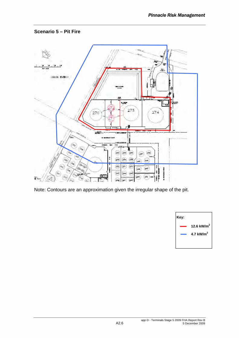
Pinnacle Risk Management
app D - Terminals Stage 5 2009 FHA Report Rev B 5 December 2009 A2.6
Scenario 5 – Pit Fire
Note: Contours are an approximation given the irregular shape of the pit.
Key:
12.6 kW/m2
4.7 kW/m2

Pinnacle Risk Management
app D - Terminals Stage 5 2009 FHA Report Rev B 5 December 2009 A2.7
Scenarios 6 and 7– Pump Bund and Vapour Recovery Unit Fires
Key:
23 kW/m2
12.6 kW/m2
4.7 kW/m2

Pinnacle Risk Management
app D - Terminals Stage 5 2009 FHA Report Rev B 5 December 2009 A2.8
Scenario 8 – Road Tanker Bay Fire
Key:
23 kW/m2
12.6 kW/m2
4.7 kW/m2

Pinnacle Risk Management
App D - Terminals Stage 5 2009 FHA Report Rev B 5 December 2009 45
7 REFERENCES
1 Pinnacle Risk Management, Revised Final Hazard Analysis, Stage 5 Expansion Modifications, Terminals Pty Ltd, Port Botany, NSW, June 2008
2 Department of Urban Affairs & Planning (NSW) Hazardous Industry Planning Advisory Paper No 6 – Guidelines for Hazard Analysis, 1992
3 Department of Urban Affairs & Planning (NSW) Hazardous Industry Planning Advisory Paper No 4 – Risk Criteria for Land Use Safety Planning, 1992
4 DUAP, Port Botany Land Use Safety Study, Overview Report, 1996
5 Lees F.P., Loss Prevention in the Process Industries, 2nd Edition 1996
6 Technica Ltd, Atmospheric Storage Tank Study for OPITSC, Singapore, London, April 1990
7 Advisory Committee on Dangerous Substances (ACDS), Major Hazards Aspects of the Transport of Dangerous Substances, 1991
8 Pinnacle Risk Management, Hazard Audit Report for Terminals Pty Ltd, at 45 Friendship Road, Port Botany, NSW, January 2002
9 Pinnacle Risk Management, Hazard Audit Report for Terminals Pty Ltd, at 45 Friendship Road, Port Botany, NSW, February 2005
10 Pinnacle Risk Management, Hazard Audit Report for Terminals Pty Ltd, at 45 Friendship Road, Port Botany, NSW, March 2008
11 Centre for Chemical Process Safety, Guidelines for Chemical Process Quantitative Risk Analysis, 2000
12 TNO, Methods for the Calculation of Physical Effects (The Yellow Book), 1997
13 ICI HAZAN Course Notes, 2000
14 TNO, Methods for the Determination of Possible Damage (The Green Book), 1992
15 Thomas, Historical Fire Incident Data Use & Sources, June 2003
16 Kletz, T., Will Cold petrol Explode in the Open Air?, Loss Prevention Bulletin 188

xoffice locationsx
Sydney Level 21, 321 Kent Street Sydney, NSW 2000 Tel: +612 8233 9900 Fax: +612 8233 9966
Brisbane Level 12, 120 Edward Street Brisbane, QLD 4000 Tel: +617 3007 3800 Fax: +617 3007 3811
Dubai Level 4, Attareen Building, Saaha Offices, Old Town Island Downtown Burj Dubai, UAE Tel: +971 4 4200212 Fax: +971 4 4200209
Melbourne Level 12, 120 Collins Street Melbourne, VIC 3000 Tel: +613 8663 4888 Fax: +613 8663 4999
Perth Ground Floor, 53 Ord Street West Perth, WA 6005 Tel: +618 9346 0500 Fax: +618 9321 7790
Australia • Asia • Middle East www.urbis.com.au [email protected]


![TRADOC (DEC2009) Afghan Smart Book [Version 1]](https://img.pdfslide.us/doc/110x75/553f63624a7959e1118b4753/tradoc-dec2009-afghan-smart-book-version-1.jpg)


![Proposal Loan Yonex(04 Dec2009)[E]](https://img.pdfslide.us/doc/110x75/55a7a59a1a28ab83198b4783/proposal-loan-yonex04-dec2009e.jpg)


![Dec2009 Fo Gg Presentation[1]](https://img.pdfslide.us/doc/110x75/5465f468b4af9f3a3f8b519c/dec2009-fo-gg-presentation1.jpg)