Embed Size (px)
Citation preview
ReconfigurableComponent-based Middleware
for Networked Embedded Systems
Paolo Costa∗, Geoff Coulson#, Cecilia Mascolo†,Luca Mottola∗, Gian Pietro Picco∗ and Stefanos Zachariadis†
#Dept. of Computing †Dept. of Computer ScienceLancaster University University College London
South Drive Gower St.Lancaster LA1 4WA, UK London WC1 6BT, UK
[email protected] {c.mascolo|s.zachariadis}@cs.ucl.ac.uk∗Dip. di Elettronica ed Informazione
Politecnico di MilanoP.zza L. Da Vinci 32Milan 20133, Italy
{costa|mottola|picco}@elet.polimi.it
Abstract
Next generation embedded systems will be composed of large numbers of heterogeneousdevices. These will typically be resource-constrained (such as sensor motes), will use differentoperating systems, and will be connected through different types of network interfaces. Ad-ditionally, they may be mobile and/or form ad-hoc networks with their peers, and will needto be adaptive to changing conditions based on context-awareness. Our focus in this paperis on the provision of a middleware framework for such system environments. Our approachis based on a small and efficient ‘middleware kernel’ which supports highly modularised andcustomisable component-based middleware services that can be tailored for specific embed-ded environments, and are runtime reconfigurable to support adaptivity. These services areprimarily communications-related but also address a range of other concerns including servicediscovery and logical mobility. In the paper we provide an overview of our approach, focus-ing in detail on both the middleware kernel and the services. We also discuss an applicationscenario in which we are currently applying and evaluating our middleware approach.
Keywords: Middleware, Embedded Systems, Reconfiguration, Mobile Computing.
1
1 Introduction
Miniature computing devices are being embedded in an increasing range of objects around us
including home appliances, cars, transport infrastructures, buildings, and people. Furthermore,
the networking of such embedded environments is enabling advanced scenarios in which devices
leverage off each other and exhibit autonomous and coordinated behaviour. Recent developments
in wireless networking are pushing these trends even further by enabling new applicative scenarios,
as witnessed by the recent surge of interest in wireless sensor networks.
However, research into such networked embedded environments has so far focused very much
on the development of miniaturised devices with increasingly powerful and general capabilities.
As a result, the software fabric that ultimately makes innovative applications possible has tended to
be overlooked. Instead, software is typically developed in an ad-hoc fashion, with little or no pro-
vision for reusable services and abstractions. Furthermore, even where attempts have been made
to provide such features, the range of devices involved in networked embedded environments in-
evitably leads to significant complexity in appropriately configuring, deploying, and dynamically
reconfiguring the software. There is therefore a need for dedicated middleware platforms for net-
worked embedded systems, with abstractions that can span the full range of heterogeneous systems,
and which also offer consistent mechanisms with which to configure, deploy, and dynamically re-
configure both system and application level software.
The work discussed in this paper is addressing the need for such middleware platforms. The
work is being carried out in the context of the EU-funded RUNES project (Reconfigurable, Ubiq-
uitous, Networked Embedded Systems), which has the general general goal of developing an ar-
chitecture for networked embedded systems that encompasses dedicated radio layers, networks,
middleware, and specialised simulation and verification tools.
Our middleware platform, which is at the heart of the RUNES architecture, is radically component-
based and encapsulates the functionality provided by its various components behind well-defined
interfaces. This decoupling not only enables one to deploy different variants of the same compo-
nent (e.g., tailored to a specific device type), but also enables dynamic reconfiguration of compo-
2
nent instances and their interconnections. This provides support for dynamic adaptation to chang-
ing conditions—a fundamental requirement in the context-aware scenarios typical of networked
embedded systems.
Our approach to middleware provision comprises two distinct and orthogonal parts: First, we
provide a foundation layer—called the middleware kernel—which is the runtime realisation of a
simple but well-defined software component model. Second, we provide on top of the middleware
kernel a layer of component frameworks that offer a configurable and extensible set of middleware
and application services. In this two-layer architecture, the software infrastruture for a specific het-
erogenous, embedded networked system is achieved by providing an appropriate implementation
or implementations of the middleware kernel, and of the required configuration of middleware (or
application) services running on top of it.
The rest of the paper is organised as follows. Section 2 illustrates an example scenario that mo-
tivates and situates our work. Next, Section 3 introduces the concepts at the core of our middleware
kernel. Then, in Section 4 we discuss a number of key component framework based middleware
services that are built on top of the middleware kernel. Related work is surveyed in Section 5.
Finally, Section 6 offers our conclusions and plans for future work.
2 A Reference Scenario
Our design and development work is grounded in a number of networked embedded systems sce-
narios that we employ throughout the RUNES project. The best developed of these is a road
transport infrastructure based scenario in which a road tunnel is instrumented with sensors and ac-
tuators to detect and guard against potential disasters arising from events such as fire or chemical
spillage. More specifically, the road tunnel is instrumented with a number of sensors (e.g. temper-
ature sensors and sensors to detect toxic fumes) which feed back to a control room. In addition,
there are various actuators present such as fire sprinklers and road traffic management signs. These
sensors and actuators are interconnected using redundant network technologies—both wired and
3
wireless—to maximise resilience in disaster situations. We also assume that potentially ‘danger-
ous’ vehices—e.g. those carrying dangerous chemicals—carry RFID tags and are detected and
tracked within the tunnel.
In the event of a disaster occurring, the sensor and actuator networks may become partitioned
and may thus need to reconfigure themselves to maintain their operational status. Furthermore,
sensor and actuator devices may need to be brought under the direct control of emergency per-
sonnel such as firemen, and this may require further ad-hoc networks to be established and may
additionally require that sensors be dynamically reprogrammed—for example, firemen may need
to poll sensor devices rather than wait for periodic push-based reports, and this may require new
software to be loaded onto the sensors.
Scenarios such as this are clearly highly heterogeneous. They involve a range of sensor and
actuator devices which may run different operating systems and be programmed in different pro-
gramming languages. They also clearly involve heterogenerous networks: wired, infrastructure-
based wireless, and ad-hoc wireless. Furthermore, such scenarios are highly dynamic—especially
during disasters—and thus require to be highly adaptive and reconfigurable. Networks must be
repaired, reconfigured and instantiated; new devices must be accommodated (e.g. devices on ve-
hices or attached to firemen); and new software must be loaded onto devices. These are precisely
the types of characteristics that our middleware platform is addressing.
3 The Middleware Kernel
This section discusses the two main elements of our middleware kernel, i.e., the component model
on which it is based (along with the associated notion of component frameworks, and the support-
ing runtime that makes it possible to manage the different entities defined in the component model
at run-time.
4
3.1 The Component Model
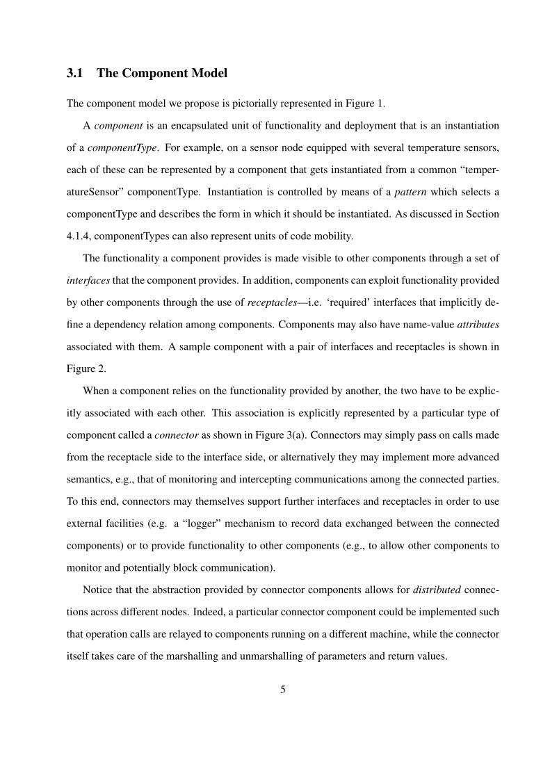
The component model we propose is pictorially represented in Figure 1.
A component is an encapsulated unit of functionality and deployment that is an instantiation
of a componentType. For example, on a sensor node equipped with several temperature sensors,
each of these can be represented by a component that gets instantiated from a common “temper-
atureSensor” componentType. Instantiation is controlled by means of a pattern which selects a
componentType and describes the form in which it should be instantiated. As discussed in Section
4.1.4, componentTypes can also represent units of code mobility.
The functionality a component provides is made visible to other components through a set of
interfaces that the component provides. In addition, components can exploit functionality provided
by other components through the use of receptacles—i.e. ‘required’ interfaces that implicitly de-
fine a dependency relation among components. Components may also have name-value attributes
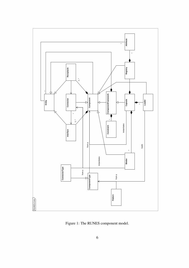
associated with them. A sample component with a pair of interfaces and receptacles is shown in
Figure 2.
When a component relies on the functionality provided by another, the two have to be explic-
itly associated with each other. This association is explicitly represented by a particular type of
component called a connector as shown in Figure 3(a). Connectors may simply pass on calls made
from the receptacle side to the interface side, or alternatively they may implement more advanced
semantics, e.g., that of monitoring and intercepting communications among the connected parties.
To this end, connectors may themselves support further interfaces and receptacles in order to use
external facilities (e.g. a “logger” mechanism to record data exchanged between the connected
components) or to provide functionality to other components (e.g., to allow other components to
monitor and potentially block communication).
Notice that the abstraction provided by connector components allows for distributed connec-
tions across different nodes. Indeed, a particular connector component could be implemented such
that operation calls are relayed to components running on a different machine, while the connector
itself takes care of the marshalling and unmarshalling of parameters and return values.
5
RU
NE
S.C
ore
Co
mp
on
ent
En
tity
Co
mp
on
entF
ram
ewo
rk
Cap
sule
Att
rib
ute
Lo
ader
Bin
der
Reg
istr
y
Inte
rfac
eR
ecep
tacl
eC
on
nec
tor
Co
nst
rain
t*
*
*
*
*
*
1..*
1..*
*
Co
mp
on
entT
ype
from
a
Co
nn
ecto
rTyp
e
load
s
inst
antia
tes
Pat
tern
from
a
inst
antia
tes
from
a
Figure 1: The RUNES component model.
6
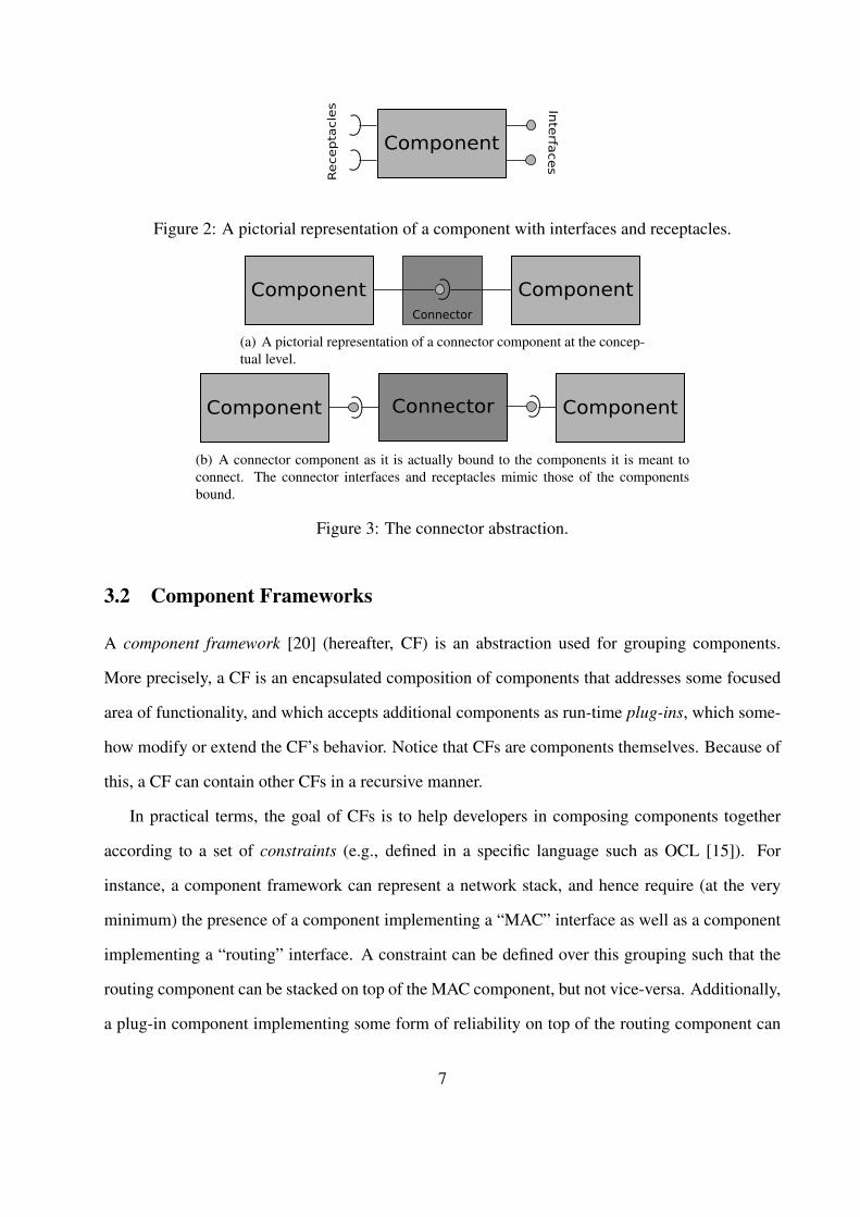
Figure 2: A pictorial representation of a component with interfaces and receptacles.
(a) A pictorial representation of a connector component at the concep-tual level.
(b) A connector component as it is actually bound to the components it is meant toconnect. The connector interfaces and receptacles mimic those of the componentsbound.
Figure 3: The connector abstraction.
3.2 Component Frameworks
A component framework [20] (hereafter, CF) is an abstraction used for grouping components.
More precisely, a CF is an encapsulated composition of components that addresses some focused
area of functionality, and which accepts additional components as run-time plug-ins, which some-
how modify or extend the CF’s behavior. Notice that CFs are components themselves. Because of
this, a CF can contain other CFs in a recursive manner.
In practical terms, the goal of CFs is to help developers in composing components together
according to a set of constraints (e.g., defined in a specific language such as OCL [15]). For
instance, a component framework can represent a network stack, and hence require (at the very
minimum) the presence of a component implementing a “MAC” interface as well as a component
implementing a “routing” interface. A constraint can be defined over this grouping such that the
routing component can be stacked on top of the MAC component, but not vice-versa. Additionally,
a plug-in component implementing some form of reliability on top of the routing component can
7
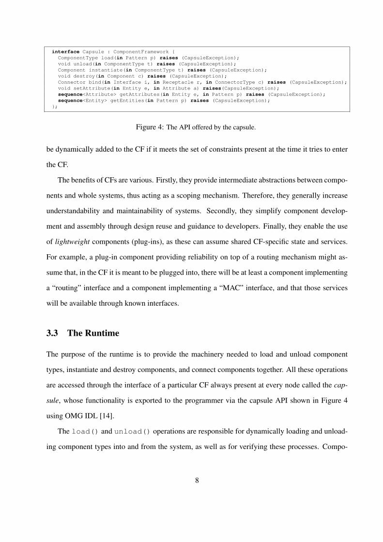
interface Capsule : ComponentFramework {ComponentType load(in Pattern p) raises (CapsuleException);void unload(in ComponentType t) raises (CapsuleException);Component instantiate(in ComponentType t) raises (CapsuleException);void destroy(in Component c) raises (CapsuleException);Connector bind(in Interface i, in Receptacle r, in ConnectorType c) raises (CapsuleException);void setAttribute(in Entity e, in Attribute a) raises(CapsuleException);sequence<Attribute> getAttributes(in Entity e, in Pattern p) raises (CapsuleException);sequence<Entity> getEntities(in Pattern p) raises (CapsuleException);
};
Figure 4: The API offered by the capsule.
be dynamically added to the CF if it meets the set of constraints present at the time it tries to enter
the CF.
The benefits of CFs are various. Firstly, they provide intermediate abstractions between compo-
nents and whole systems, thus acting as a scoping mechanism. Therefore, they generally increase
understandability and maintainability of systems. Secondly, they simplify component develop-
ment and assembly through design reuse and guidance to developers. Finally, they enable the use
of lightweight components (plug-ins), as these can assume shared CF-specific state and services.
For example, a plug-in component providing reliability on top of a routing mechanism might as-
sume that, in the CF it is meant to be plugged into, there will be at least a component implementing
a “routing” interface and a component implementing a “MAC” interface, and that those services
will be available through known interfaces.
3.3 The Runtime
The purpose of the runtime is to provide the machinery needed to load and unload component
types, instantiate and destroy components, and connect components together. All these operations
are accessed through the interface of a particular CF always present at every node called the cap-
sule, whose functionality is exported to the programmer via the capsule API shown in Figure 4
using OMG IDL [14].
The load() and unload() operations are responsible for dynamically loading and unload-
ing component types into and from the system, as well as for verifying these processes. Compo-
8
nentTypes are described by the given ‘pattern’ which specifies a predicate over name-value pairs
attached to componentTypes.
The instantiate() and destroy() operations manage the lifecycle of components. The
former takes as its parameter a componentType from which an actual component is instantiated,
whereas the latter takes a component instance (that can possibly be even a connector) and destroys
it.
The connect() operation is responsible for establishing connections between pairs of com-
ponents. To this end, it takes an interface/receptacle pair, and the componentType of a connector
that express the required semantics of the connection. It returns an instance of a connector compo-
nent representing the connection.
The remaining operations are responsible for managing attributes associated with entities. In
particular, the setAttribute() operation allows insertion and removal of attributes (with the
removal operation achieved by setting an attribute with an undefined value); the getAttributes()
operation provides a list of all attributes associated with a particular entity that match a given pat-
tern; and the getEntitites() operation retrieves the set of all entities contained in the capsule
that have attributes matching the given pattern. These operations are also used internally by the
capsule for automatically inserting in an internal registry information on the operations performed
up to a given moment. For instance, when a component is instantiated, the capsule might insert in
the registry information on its name, the interfaces it provides, and the receptacles it defines.
The functionality offered by the capsule can be internally delegated to three underlying, inde-
pendent components, i.e. a loader component, a binder component and a registry component. In
addition, notice that the capsule itself (with its internal constituents binder, loader and registry) is
designed so that the functionality it is meant to provide can be implemented differently on differ-
ent devices, e.g., this might be realised as processes on a PDA, or as executable binary code stored
on a chip. This flexibility is key to handling the heterogeneity of the scenarios we target. Note,
however, that RUNES system builders who engineer systems out of existing components and CFs
only need to know the capsule API.
9
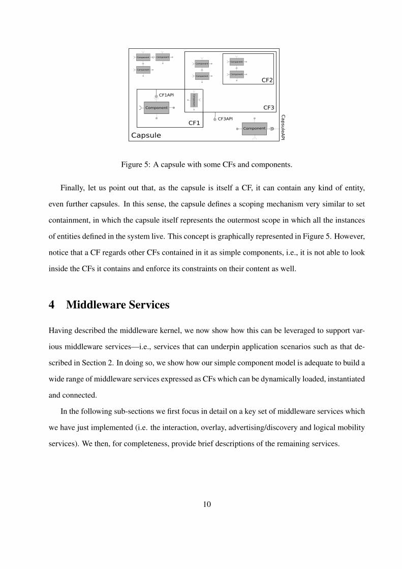
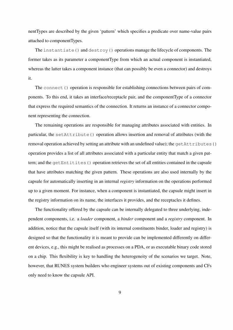
Figure 5: A capsule with some CFs and components.
Finally, let us point out that, as the capsule is itself a CF, it can contain any kind of entity,
even further capsules. In this sense, the capsule defines a scoping mechanism very similar to set
containment, in which the capsule itself represents the outermost scope in which all the instances
of entities defined in the system live. This concept is graphically represented in Figure 5. However,
notice that a CF regards other CFs contained in it as simple components, i.e., it is not able to look
inside the CFs it contains and enforce its constraints on their content as well.
4 Middleware Services
Having described the middleware kernel, we now show how this can be leveraged to support var-
ious middleware services—i.e., services that can underpin application scenarios such as that de-
scribed in Section 2. In doing so, we show how our simple component model is adequate to build a
wide range of middleware services expressed as CFs which can be dynamically loaded, instantiated
and connected.
In the following sub-sections we first focus in detail on a key set of middleware services which
we have just implemented (i.e. the interaction, overlay, advertising/discovery and logical mobility
services). We then, for completeness, provide brief descriptions of the remaining services.
10
Figure 6: Interaction CF.
4.1 Key Middleware Services
4.1.1 Interaction Service
The interaction service CF plays the crucial role of exporting middleware-level communications
services to applications. A middleware platform that offers only a single ‘interaction paradigm’
(e.g messaging or RPC) cannot cope with the diversity of requirements imposed by our target
application domain. Instead, a comprehensive solution needs to provide a wide range of interaction
paradigms including publish-subscribe, eventing, group communication, streaming, tuple-spaces,
etc. To address this requirement, the interaction CF supports plug-in interaction paradigms (called
PIPs for short). See Figure 6.
The design of the interaction CF is guided by the following principles:
• The selection, configuration the use of PIP components by application developers should
be as straightforward as possible, and their management should be based on a declarative
specification of the desired behaviour by the application programme.
• The API of each PIP should be independent of how it is implemented (for example, over
different network types and conditions.
• The (re-)configuration of PIPs should also be influenced by the current environmental con-
text such as available network infrastructure or other changing environmental conditions.
To help maintain a uniform “look-and-feel” for PIP APIs, the interaction CF defines an extensible
set of generic APIs which are intended to be useful for commonly-used families of PIPs (e.g. a
family of publish-subscribe PIPs). In cases where none of these generic APIs is suitable for a
11
newly-developed PIP, the CF recommends the use of interface inheritance wherever possible to
specialise an existing API, thus avoiding a proliferation of top-level APIs.
To enable applications to select and configure PIPs, each PIP interface has attached to it a set of
name-value attributes that embody PIP-specific information such as name of the PIP, its purpose,
constraints on its use and the QoS it provides. Correspondingly, the receptacle of an application
component that wants to use a specific PIP has a set of predicates attached to it whose terms refer
to the attributes attached to potentially-matching PIPs. Then, when offered a receptacle by the
application (using the IConnect interface; see Figure 6), the interaction CF selects, instantiates
and configures a suitable PIP based on matching the application’s predicates with the attributes
exported by the set of currently installed PIPs. In addition, as well as application attributes, predi-
cates can refer to dynamic attributes that represent information provided by a context engine. For
example, this information may refer to the type of network the host machine is currently connected
to.
Having achieved a suitable match of application attributes, predicates, and dynamic attributes,
the CF creates a contract that records the particular values that were used in creating the match.
If this contract is violated during the use of the selected PIP by any of the three parties involved
(i.e. the application, the PIP and the context engine), an exception is raised. This can occur, for
example, if a dynamic attribute from the context engine changes; or if the application attempts to
renegotiate the contract by altering the predicates attached to its receptacle. Exceptions are initially
handled by the interaction CF itself, which attempts to restore the contract. If this attempt fails the
exception is passed on to the application.
An example PIP.
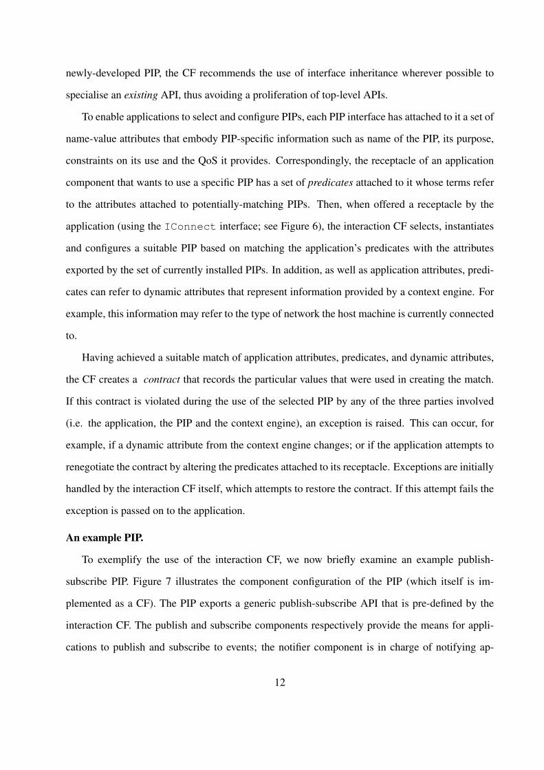
To exemplify the use of the interaction CF, we now briefly examine an example publish-
subscribe PIP. Figure 7 illustrates the component configuration of the PIP (which itself is im-
plemented as a CF). The PIP exports a generic publish-subscribe API that is pre-defined by the
interaction CF. The publish and subscribe components respectively provide the means for appli-
cations to publish and subscribe to events; the notifier component is in charge of notifying ap-
12
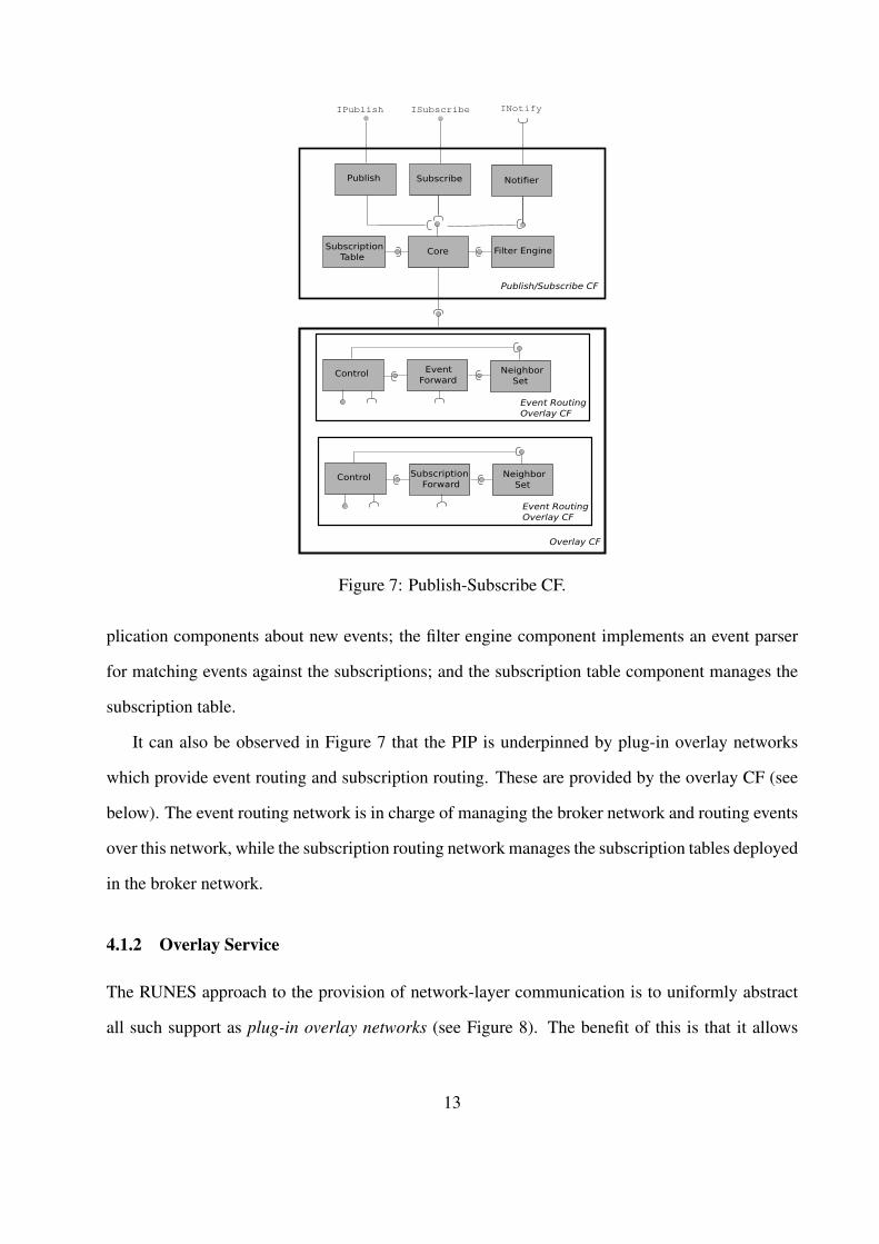
Figure 7: Publish-Subscribe CF.
plication components about new events; the filter engine component implements an event parser
for matching events against the subscriptions; and the subscription table component manages the
subscription table.
It can also be observed in Figure 7 that the PIP is underpinned by plug-in overlay networks
which provide event routing and subscription routing. These are provided by the overlay CF (see
below). The event routing network is in charge of managing the broker network and routing events
over this network, while the subscription routing network manages the subscription tables deployed
in the broker network.
4.1.2 Overlay Service
The RUNES approach to the provision of network-layer communication is to uniformly abstract
all such support as plug-in overlay networks (see Figure 8). The benefit of this is that it allows
13
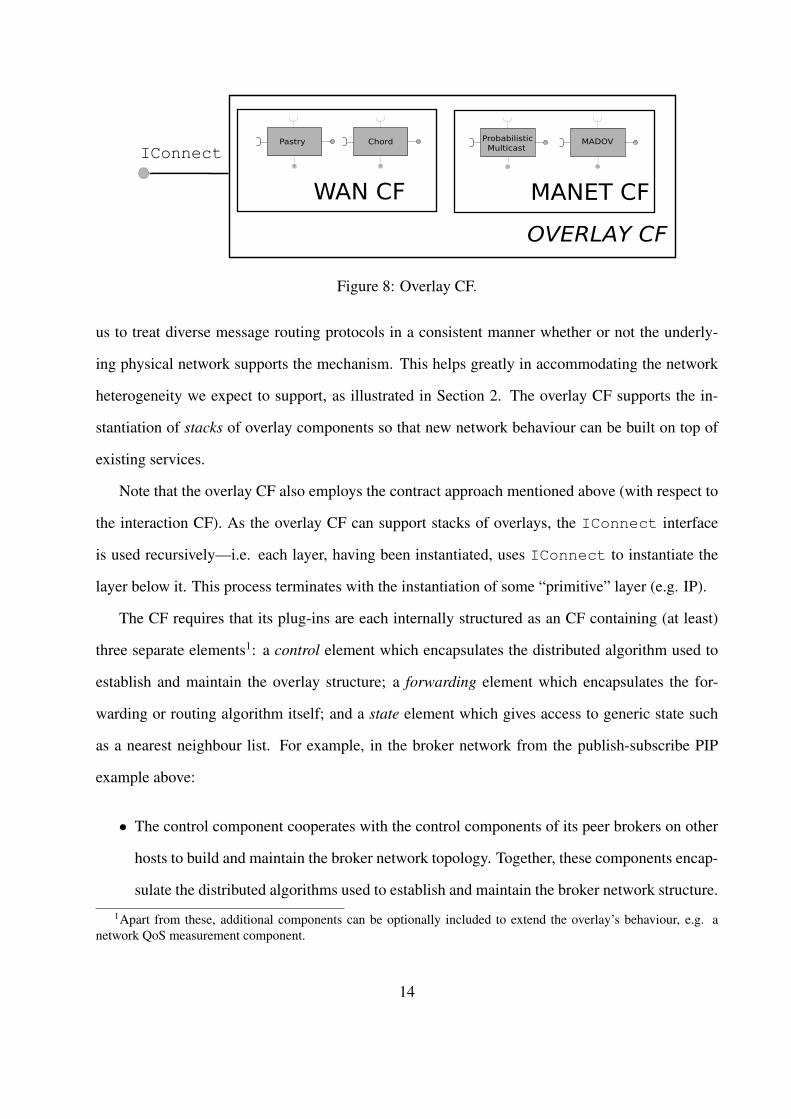
Figure 8: Overlay CF.
us to treat diverse message routing protocols in a consistent manner whether or not the underly-
ing physical network supports the mechanism. This helps greatly in accommodating the network
heterogeneity we expect to support, as illustrated in Section 2. The overlay CF supports the in-
stantiation of stacks of overlay components so that new network behaviour can be built on top of
existing services.
Note that the overlay CF also employs the contract approach mentioned above (with respect to
the interaction CF). As the overlay CF can support stacks of overlays, the IConnect interface
is used recursively—i.e. each layer, having been instantiated, uses IConnect to instantiate the
layer below it. This process terminates with the instantiation of some “primitive” layer (e.g. IP).
The CF requires that its plug-ins are each internally structured as an CF containing (at least)
three separate elements1: a control element which encapsulates the distributed algorithm used to
establish and maintain the overlay structure; a forwarding element which encapsulates the for-
warding or routing algorithm itself; and a state element which gives access to generic state such
as a nearest neighbour list. For example, in the broker network from the publish-subscribe PIP
example above:
• The control component cooperates with the control components of its peer brokers on other
hosts to build and maintain the broker network topology. Together, these components encap-
sulate the distributed algorithms used to establish and maintain the broker network structure.
1Apart from these, additional components can be optionally included to extend the overlay’s behaviour, e.g. anetwork QoS measurement component.
14
Figure 9: Elements of overlay plug-ins.
• The forwarder component routes events over the broker network and implements specific
event forwarding strategies (e.g. different forwarding strategies can be provided as pluggable
forwarding components).
• The state component encapsulates key state such as nearest broker neighbours list, connected
clients list (i.e. publishers, subscribers).
The main benefit of this three-fold structure is that it can naturally support fine-grained lay-
ering and combining of multiple overlays so that, for example, different forwarding elements can
simultaneously be in operation over the same control elements (e.g. in a flooding overlay such
as Gnutella, we might simultaneously employ different flooding strategies over the same over-
lay topology). In addition, the use of common architectural elements ensures that we can repre-
sent generalised dependencies between overlays (as we can implement overlays to well-defined
common interfaces); and also we can easily perform fine-grained reconfiguration of individual
overlays; i.e. we can add or change the individual behaviour of an overlay as and when the envi-
ronmental context changes.
The three elements of each plug-in overlay interact within the individual CF as shown by the
bi-directional arrows in Figure 9. The exported interfaces and receptacles are used to express
dependencies on other overlay network implementations. The control component presents the
IControl interface with common operations to create, join and leave an overlay network. The
forwarding component has operations to route messages to nodes in the overlay network, send
messages to neighbour nodes, and receive any incoming messages. The control component also
exports an IForward receptacle to allow it to forward control messages via its own, or a different
15
overlay’s, forwarding mechanism. Similarly, the control component exports an IDeliver inter-
face; this is used by lower-level overlays networks, which, when they receive a message, pass it to
the control component atop. Particular IDeliver implementations determine how to deal with
incoming messages (e.g., react to them, forward them etc.). Finally, the forwarding component
exports an IForward receptacle that allows it to directly forward messages using the underlying
implementation.
4.1.3 Advertising and Discovery Service
As new application components are dynamically added to systems to provide new services, there is
a need for mechanisms to enable applications to advertise and discover these components/services.
For instance, in the tunnel scenario of Section 2, one may deploy a new application component able
to perform aggregation on data stored at temperature sensors. Using the advertising and discovery
service (ADS), this new component can advertise itself to the rest of the system so that remote
nodes can be made aware of its presence and ask for its code if they need it (the latter functionality
is provided by the logical mobility service, described below).
There are many different ways to do advertising and discovery, and imposing particular mech-
anisms can hinder interoperability with other systems. Hence, in the spirit of the interaction and
overlay services already discussed, we provide a dynamic and flexible framework, which is based
on work described in [26].
The ADS CF is built around a set of interfaces called Advertiser, Advertisable, Discovery and
ComponentListener. Components that wish to advertise their presence implement the Advertisable
interface which exports a method that returns a message that the advertisable component uses to
express information that it requires advertised.
Advertiser interfaces are used to abstract over multiple advertising mechanisms implemented
inside so-called advertiser components. These are responsible for accepting messages from ad-
vertisable components, (potentially) transforming them into another format, and then actually per-
forming the advertisement in the appropriate manner. A combination of component availability
16
notification and advertiser registration enables advertisable components to register to be notified
when specific advertisers are added to the system. Advertisable components can then register to
be advertised by them. Moreover, advertisable components can express that they require particular
advertisers. Thus, the semantics of the advertisable message are not a-priori defined but rather
depend on the advertisable component and on the particular advertising mechanism (i.e. the adver-
tiser component) used.
Note that a component can implement both the Advertiser and the Advertisable interfaces. This
allows for the advertising of advertising mechanisms; in this way, for example, the existence of a
multicast advertising group can be advertised using a broadcast advertiser. Combined with the use
of logical mobility (see below), this allows a host to dynamically acquire a new advertising and
discovery mechanism for a network that was just detected. For example, on approaching a Jini
network [23], a node can request and download the components that are needed to advertise to,
and use functionality from, this network.
Turning now to the ‘discovery’ side, different discovery techniques are encapsulated within
discovery components which implement the Discovery interface. There can be any number of dis-
covery components installed in a capsule. Discovery components act as registries of advertisable
components located remotely. So-called RemoteComponents’ are used to represent components
which have been found remotely. These do not directly export any functionality to local com-
ponents; rather, they only export methods needed to access their properties, and their location
and advertising messages. Hence, discovery components act as collectors of RemoteComponent
references, which can be added and removed dynamically as they are discovered.
Discovery components emit events representing the availability of remote components. Local
components can register a ComponentListener with a discovery component, to be notified when
components satisfying a given set of attributes are located. Users of the ADS CF can use the logical
mobility service (discussed below), to dynamically deploy advertising and discovery components,
as well as request, receive and deploy components that have been located remotely.
17
4.1.4 Logical Mobility Service
‘Logical mobility’ refers to the ability to change the configuration of the software of a distributed
system by transferring logical units (in our case, primarily ComponentTypes) between nodes. Log-
ical mobility has been repeatedly argued [3, 9, 17] to have great potential in the engineering of
mobile systems. In summary, the arguments are as follows:
• It allows applications to update their codebase, and hence acquire new functionality.
• It may permit interoperability with remote applications and environments, which had not
been envisioned at design time.
• It potentially achieves the efficient use of peer resources, as computationally expensive cal-
culations can be offloaded to the environment.
• It facilitates the efficient use of local resources, as infrequently-used functionality can be
removed to free some of the limited memory that mobile devices are equipped with. The
functionality may potentially be retrieved later when needed.
• It can be used to encapsulate, request and transfer functionality between nodes; hence it is a
tool that can be used to create adaptable systems.
• By allowing functionality to be retrieved locally, it allows for autonomous operation instead
of relying on an externally provided service.
The main purpose of our logical mobility service (LMS) is to allow the system to dynamically
reconfigure by acquiring functionality from its peers. This component framework is based on work
reported in [26].
The Logical Mobility Unit.
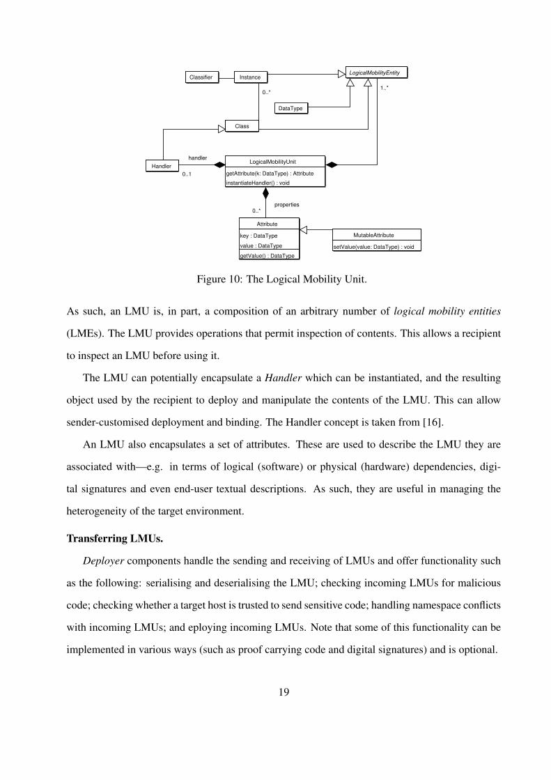
A logical mobility unit (LMU) (see Figure 10) is defined as the minimal unit of transfer. An
LMU is a container that can encapsulate various constructs and representations of code and data2.2Note that Figure 10 presents the framework as an object-oriented one. In implementations in which classes and
objects are not available, other constructs (such as dynamic libraries) are used.
18
Attribute
key : DataType
value : DataType
getValue() : DataType
Classifier Instance
LogicalMobilityUnit
getAttribute(k: DataType) : Attribute
instantiateHandler() : void
LogicalMobilityEntity
Class
Handler
DataType
MutableAttribute
setValue(value: DataType) : void
0..*properties
0..1
handler
1..*0..*
Figure 10: The Logical Mobility Unit.
As such, an LMU is, in part, a composition of an arbitrary number of logical mobility entities
(LMEs). The LMU provides operations that permit inspection of contents. This allows a recipient
to inspect an LMU before using it.
The LMU can potentially encapsulate a Handler which can be instantiated, and the resulting
object used by the recipient to deploy and manipulate the contents of the LMU. This can allow
sender-customised deployment and binding. The Handler concept is taken from [16].
An LMU also encapsulates a set of attributes. These are used to describe the LMU they are
associated with—e.g. in terms of logical (software) or physical (hardware) dependencies, digi-
tal signatures and even end-user textual descriptions. As such, they are useful in managing the
heterogeneity of the target environment.
Transferring LMUs.
Deployer components handle the sending and receiving of LMUs and offer functionality such
as the following: serialising and deserialising the LMU; checking incoming LMUs for malicious
code; checking whether a target host is trusted to send sensitive code; handling namespace conflicts
with incoming LMUs; and eploying incoming LMUs. Note that some of this functionality can be
implemented in various ways (such as proof carrying code and digital signatures) and is optional.
19
Deployers offer an API that allows sending and receiving LMUs. If it is available, they can
interact with the ADS CF to allow the requesting and deploying of RemoteComponents.
Deploying LMUs.
When transferring an LMU to a target host, we need to define where, logically, the LMU will
be deployed. In terms of the RUNES middleware, a valid logical target is a component. As such,
the LMS defines an adaptable component as a component that can receive LMUs at runtime. We
represent these components as components that implement the Adaptable interface.
By default, LMUs are deployed in capsules - this allows components to be encapsulated in
LMUs and deployed dynamically. If this is not the intent of the sender, alternative components can
be specified. This allows for adapting individual components with another codebase.
4.2 Other Key Middleware Services
We now briefly describe some other component frameworks that play key roles in the RUNES
middleware platform.
Local OS Service As already mentioned, our component model can “reach down” into layers be-
longing to the operating system. This way, we provide a unified abstraction on top of which
mechanisms ranging from MAC layers up to application components can be realized. To this
end, the local OS service aims at providing a collection of services that realize an abstraction
layer over operating system functionalities. For instance, components implementing differ-
ent scheduling policies or memory management techniques can be provided within this CF.
As intra-layer integration is of paramount importance on constrained embedded devices [1],
having operating system functionalities exported thorugh the same abstraction used to de-
velop applications clearly fosters the exploitation of information provided by lower layers.
For instance, an application component might adjust the communication range on a sensor
device by modifying the tranmission power.
Context and Location Sensing Service Networked embedded systems are envisioned to operate
20
unattended and in a manner that is closely integrated with the physical environment. In such
scenarios, the system needs to sense the surrounding conditions and perform adaptation if
needed. To this end, mechanisms are needed for sensing the context in which the system
is operating and providing this information to other components (e.g. the interaction and
overlay services as discussed above) so that they can suitably adapt their behaviors. As
other examples, a device equipped with a GPS receiver can detect movement and inform
components interested in this fact on the new position. The goal of the context and location
sensing service is to provide a unified abstraction of all such functionaly, so as to shield other
components from low-level implementation details.
Sensor Coordination Service Various kinds of coordination are needed in sensor networks. For
instance, time synchronization is necessary to precisely relate sensed events, or to coordinate
sleep periods when sensor devices turn their radio off. However, general coordination in
large-scale distributed systems composed of constrained devices is hard to achieve. The goal
of the sensor coordination service is to provide efficient coordination mechanisms designed
for being integrated with the rest of the framework we propose. In particular, it is designed
in a way that facilitates its integration with other components so that coordination can be
exploited at different levels, from the operating system up to the application.
5 Related Work
There is a substantial body of literature on reconfigurable middleware systems. First, the RUNES
middleware builds on our earlier work on the OpenCOM component model [5]. Compared to this
earlier work, there in an increased emphasis in RUNES on a formal, model-driven, approach; and
on specialisation to the networked embedded systems domain. Apart from this, Gravity [4] is a
component model built on top of the Open Services Gateway Initiative (OSGi) Framework [21]
(OSGi is a commercial framework for the Java platform which allows providers to deliver services
to consumer devices attached to a residential network and to manage those devices remotely).
21
P2PComp [8] is a lightweight service-oriented component model for mobile devices, which is also
built using OSGi; it provides location independent synchronous and asynchronous communica-
tion between components. The Dynamically Programmable and Reconfigurable Software (DPRS)
architecture [18] is a component-based design for dynamically programmable and reconfigurable
systems. PCOM [2] is a distributed component model for pervasive computing. It allows for de-
signing applications as a collection of potentially distributed components, which make their depen-
dencies explicit. If those dependencies are invalidated, PCOM can attempt to automatically adapt
by detecting alternatives according to various strategies. FarGo-DA [24] is a distributed compo-
nent model that uses logical mobility to allow disconnected operation. The Software Dock [11] is
an agent-based software deployment network that allows negotiation between software producers
and consumers. THINK [7] presents an approach for building component-based operating system
kernels. And finally, one.world [10] is a system for pervasive applications that supports dynamic
service composition, migration of applications and discovery of context.
Other component based systems from the embedded systems community are Pebble [13],
PECOS [25], PBO [19], SaveCCM [12] and Koala [22]. Most of these are build-time only
technologies-components are not visible at run-time and therefore these systems do not support
dynamic reconfiguration. One area that some of these systems (i.e. PECOS and PECT) do support,
however, that our model does not natively support, is the specification (at build-time) of real-time
constraints such as cycle time or worst case execution time. Such facilities are clearly important
in certain real-time critical areas. Our approach to providing such facilities, where needed, is to
provide a suitable ‘real-time systems’ CF rather than building-in real-time properties into the pro-
gramming model itself. A further observation is that many of these embedded systems technologies
(e.g. PBO, SaveCCM, and Koala) are tightly coupled to an specific underlying OS environment
and/or are programming language specific.
There are two main difference between the approaches outlined above and our work. The
first difference relates to generality: RUNES is a generic software fabric that is designed from
the ground up to be implementable on a wide range of devices, and the primitives we provide are
22
not limited to, for example, disconnected operation or software deployment or real-time support,
but can indeed be used to build such services. The second difference relates to our two-layer
architecture in which systems are built by selecting (and dynamically reconfiguring) appropriate
CF-based middleware services on top of the middleware kernel. This capability, which is lacking
in lacking in other work, results in significantly greater flexibility than other systems offer.
6 Conclusions
In this paper we have described the RUNES approach to the development of software for net-
worked embedded systems. This employs a uniform “software component” abstraction which can
be variously realised in various types of devices. Then, on top of the basic component model, we
layer the notion of component frameworks which realise various areas of functionality that can be
configured-in or left out as required. We have shown in the paper how these abstract notions can be
instantiated as useful and general functionality, both local and distributed, in adaptive networked
embedded environments.
The current status of our work is that we have implemented the middleware kernel in two
different languages (Java and C) and have deployed it on devices ranging from PCs to PDAs to
tiny sensor devices running the Contiki OS [6]. We have thus verified that our approach is viable
even in extremely resource-constrained environments. We have also implemented the four main
middleware services described in the paper and deployed these in a demonstration scenario based
on that outlined in Section 2. This work has convinced us of the generality and utility of our
approach.
In our future work we are looking to further explore the adaptivity and reconfigurability capa-
bilities of our middleware. This will especially involve the dynamic deployment and adaptation of
new PIPs and overlays in the tunnel fire scenario.
23
Acknowledgments
The authors would like to thank their partners in the RUNES Project and to acknowledge the
financial support given to this research by the European Commission.
References
[1] I. Akyildiz, W. Su, Y. Sankarasubramaniam, and E. Cayirci. A survey on sensor networks.
IEEE Communication Mag., 40(8):102–114, 2002.
[2] C. Becker, M. Handte, G. Schiele, and K. Rothermel. PCOM - A Component System for
Pervasive Computing. In Proceedings of the 2nd International Conference on Pervasive
Computing and Communications, Orlando, Florida, March 2004.
[3] L. Capra, C. Mascolo, S. Zachariadis, and W. Emmerich. Towards a Mobile Computing
Middleware: a Synergy of Reflection and Mobile Code Techniques. In In Proc. of the 8th
IEEE Workshop on Future Trends of Distributed Computing Systems (FTDCS’2001), pages
148–154, Bologna, Italy, October 2001.
[4] H. Cervantes and R. Hall. Autonomous Adaptation to Dynamic Availability Using a Service-
Oriented Component Model. In Proceedings of the 26th International Conference of Software
Engineering (ICSE 2004), pages 614–623, Edinburgh, Scotland, May 2004. ACM Press.
[5] G. Coulson, G. Blair, P. Grace, A. Joolia, K. Lee, and J. Ueyam. A Component Model
for Building Systems Software. In Proc. IASTED Software Engineering and Applications
(SEA’04), Nov 2004.
[6] A. Dunkels, B. Groenvall, and T. Voigt. Contiki - a lightweight and flexible operating sys-
tem for tiny networked sensors. In Proceedings of the First IEEE Workshop on Embedded
Networked Sensors, Tampa, Florida, USA, November 2004.
24
[7] Jean-Philippe Fassino, Jean-Bernard Stefani, Julia Lawall, and Gilles Muller. THINK: a
software framework for component-based operating system kernels. In 2002 USENIX Annual
Technical Conference, pages 73–86, Monterey, CA, June 2002. USENIX.
[8] A. Ferscha, M. Hechinger, R. Mayrhofer, and R.Oberhauser. A Light-Weight Component
Model for Peer-to-Peer Applications. In 2nd International Workshop on Mobile Distributed
Computing. IEEE Computer Society Press, March 2004.
[9] A. Fuggetta, G. Picco, and G. Vigna. Understanding Code Mobility. IEEE Transactions on
Software Engineering, 24(5):342–361, May 1998.
[10] R. Grimm, T. Anderson, B. Bershad, and D. Wetherall. A system architecture for pervasive
computing. In Proceedings of the 9th workshop on ACM SIGOPS European workshop, pages
177–182. ACM Press, 2000.
[11] R. S. Hall, D. Heimbigner, and A. L. Wolf. A Cooperative Approach to Support Software
Deployment Using the Software Dock. In Proceedings of the 1999 International Conference
on Software Engineering, pages 174–183. IEEE Computer Society Press / ACM Press, 1999.
[12] H. Hansson, M. Akerholm, I. Crnkovic, and M. Torngren. SaveCCM – a component model
for safety-critical real-time systems, September 2004.
[13] K. Magoutis, J. Brustoloni, E. Gabber, W. Ng, and A. Silberschatz. Building Appliances
out of Reusable Components using Pebble. In Proc. SIGOPS European Workshop, pages
211–216, Kolding, Denmark, September 2000. ACM Press.
[14] Object Management Group. OMG IDL specification.
www.omg.org/technology/documents/idl2x spec catalog.htm.
[15] Object Management Group. UML 2.0 OCL specification. www.omg.org/docs/ptc/03-10-
14.pdf.
25
[16] G.P. Picco. µCODE: A Lightweight and Flexible Mobile Code Toolkit. In K. Rothermel and
F. Hohl, editors, Proc. 2nd Int. Workshop on Mobile Agents, LNCS 1477. Springer-Verlag,
1998.
[17] G.-C. Roman, A. L. Murphy, and G. P. Picco. A Software Engineering Perspective on Mo-
bility. In A. C. W. Finkelstein, editor, Future of Software Engineering. ACM Press, 2000.
[18] M. Roman and N. Islam. Dynamically Programmable and Reconfigurable Middleware Ser-
vices. In Proceedings of Middleware ’04, Toronto, October 2004.
[19] D. Stewart, R. Volpe, and P. Khosla. Design of Dynamically Reconfigurable Real-Time
Software using Port-Based Objects. Technical Report CMU-RI-TR-93-11, Robotics Institute,
Carnegie Mellon University, July 1993.
[20] C. Szyperski. Component Software: Beyond Object-Oriented Programming. Addison-
Wesley, 1999.
[21] The OSGi Alliance. The OSGi framework. http://www.osgi.org, 1999.
[22] R. van Ommering, F. van der Linden, J. Kramer, and J. Magee. The Koala Component Model
for Consumer Electronics Software. IEEE Computer, 33(3):78–85, March 2000.
[23] J. Waldo. The Jini Architecture for Network-centric Computing. Communications of the
ACM, 42(7):76–82, July 1999.
[24] Y. Weinsberg and I. Ben-Shaul. A Programming Model and System Support for
Disconnected-Aware Applications on Resource-Constrained Devices. In Proceedings of the
24th International Conference on Software Engineering, pages 374–384, May 2002.
[25] M. Winter, T. Genbler, A. Christoph, O. Nierstrasz, S. Ducasse, R Wuyts, G. Arevalo,
P. Muller, C. Stich, and B. Schonhage. Components for embedded software: the PECOS
approach. In Proc. International Conference on Compilers, Architecture, and Synthesis for
Embedded Systems (CASES ’02), pages 19–26, Grenoble, France, 2002. ACM Press.
26
[26] S. Zachariadis, C. Mascolo, and W. Emmerich. SATIN: A Component Model for Mobile Self-
Organisation. In International Symposium on Distributed Objects and Applications (DOA),
Agia Napa, Cyprus, October 2004. Springer.
27