Embed Size (px)
Citation preview
Performance Comparison of the Prototype
Reconfigurable Antenna with Commercial LMR
Antennas
Mahmud Harun∗ , Akshay Kumar and S.W. Ellingson
April 10, 2012
∗Bradley Dept. of Electrical & Computer Engineering, 444 Durham Hall, Virginia Polytechnic Institute& State University, Blacksburg, VA 24061 USA. E-mail: [email protected]
1
Contents
1 Introduction 3
2 Comparison of s11 4
3 Comparison of Audio SNR 8
4 Conclusion 11
2
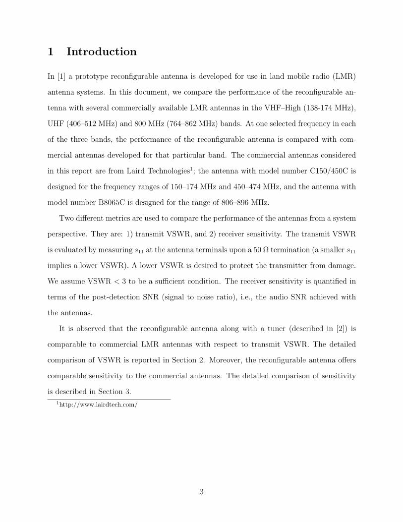
1 Introduction
In [1] a prototype reconfigurable antenna is developed for use in land mobile radio (LMR)
antenna systems. In this document, we compare the performance of the reconfigurable an-
tenna with several commercially available LMR antennas in the VHF–High (138-174 MHz),
UHF (406–512 MHz) and 800 MHz (764–862 MHz) bands. At one selected frequency in each
of the three bands, the performance of the reconfigurable antenna is compared with com-
mercial antennas developed for that particular band. The commercial antennas considered
in this report are from Laird Technologies1; the antenna with model number C150/450C is
designed for the frequency ranges of 150–174 MHz and 450–474 MHz, and the antenna with
model number B8065C is designed for the range of 806–896 MHz.
Two different metrics are used to compare the performance of the antennas from a system
perspective. They are: 1) transmit VSWR, and 2) receiver sensitivity. The transmit VSWR
is evaluated by measuring s11 at the antenna terminals upon a 50 Ω termination (a smaller s11
implies a lower VSWR). A lower VSWR is desired to protect the transmitter from damage.
We assume VSWR < 3 to be a sufficient condition. The receiver sensitivity is quantified in
terms of the post-detection SNR (signal to noise ratio), i.e., the audio SNR achieved with
the antennas.
It is observed that the reconfigurable antenna along with a tuner (described in [2]) is
comparable to commercial LMR antennas with respect to transmit VSWR. The detailed
comparison of VSWR is reported in Section 2. Moreover, the reconfigurable antenna offers
comparable sensitivity to the commercial antennas. The detailed comparison of sensitivity
is described in Section 3.
1http://www.lairdtech.com/
3
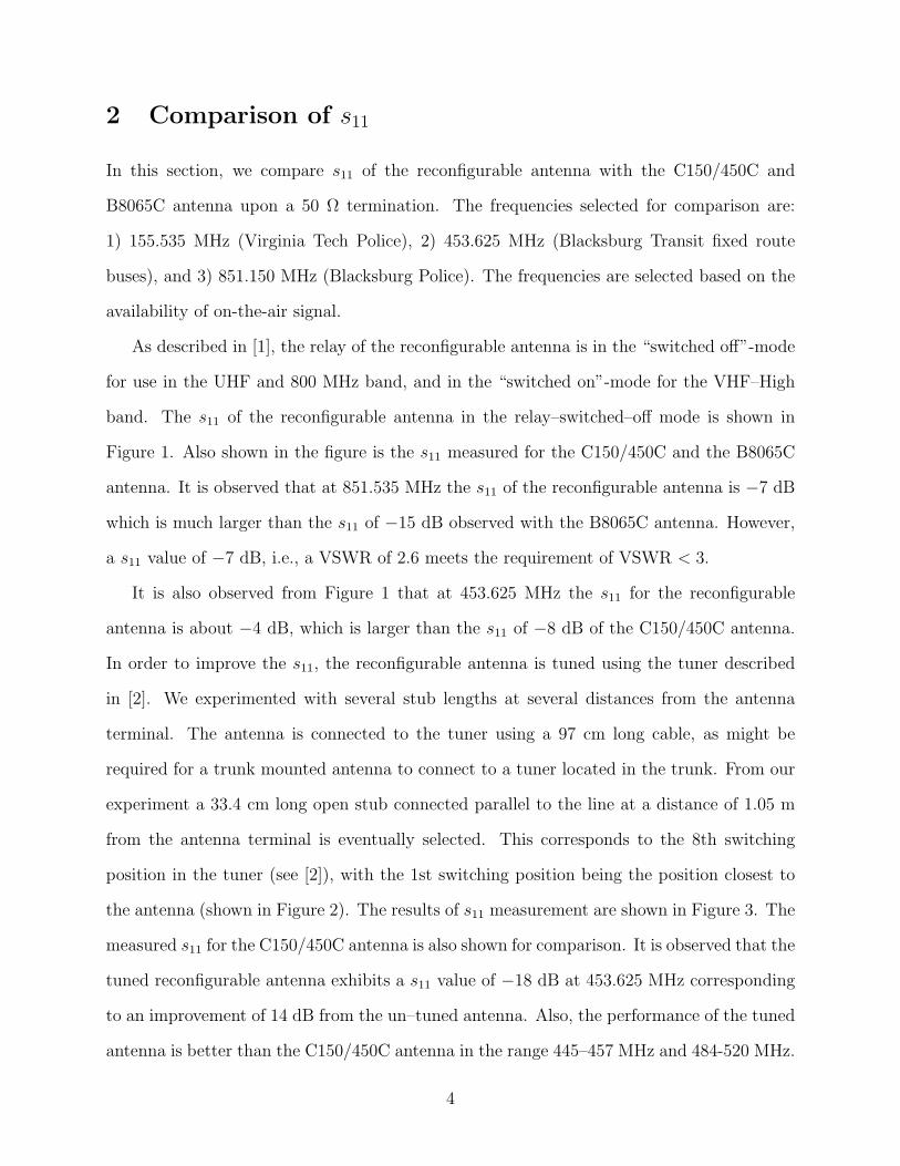
2 Comparison of s11
In this section, we compare s11 of the reconfigurable antenna with the C150/450C and
B8065C antenna upon a 50 Ω termination. The frequencies selected for comparison are:
1) 155.535 MHz (Virginia Tech Police), 2) 453.625 MHz (Blacksburg Transit fixed route
buses), and 3) 851.150 MHz (Blacksburg Police). The frequencies are selected based on the
availability of on-the-air signal.
As described in [1], the relay of the reconfigurable antenna is in the “switched off”-mode
for use in the UHF and 800 MHz band, and in the “switched on”-mode for the VHF–High
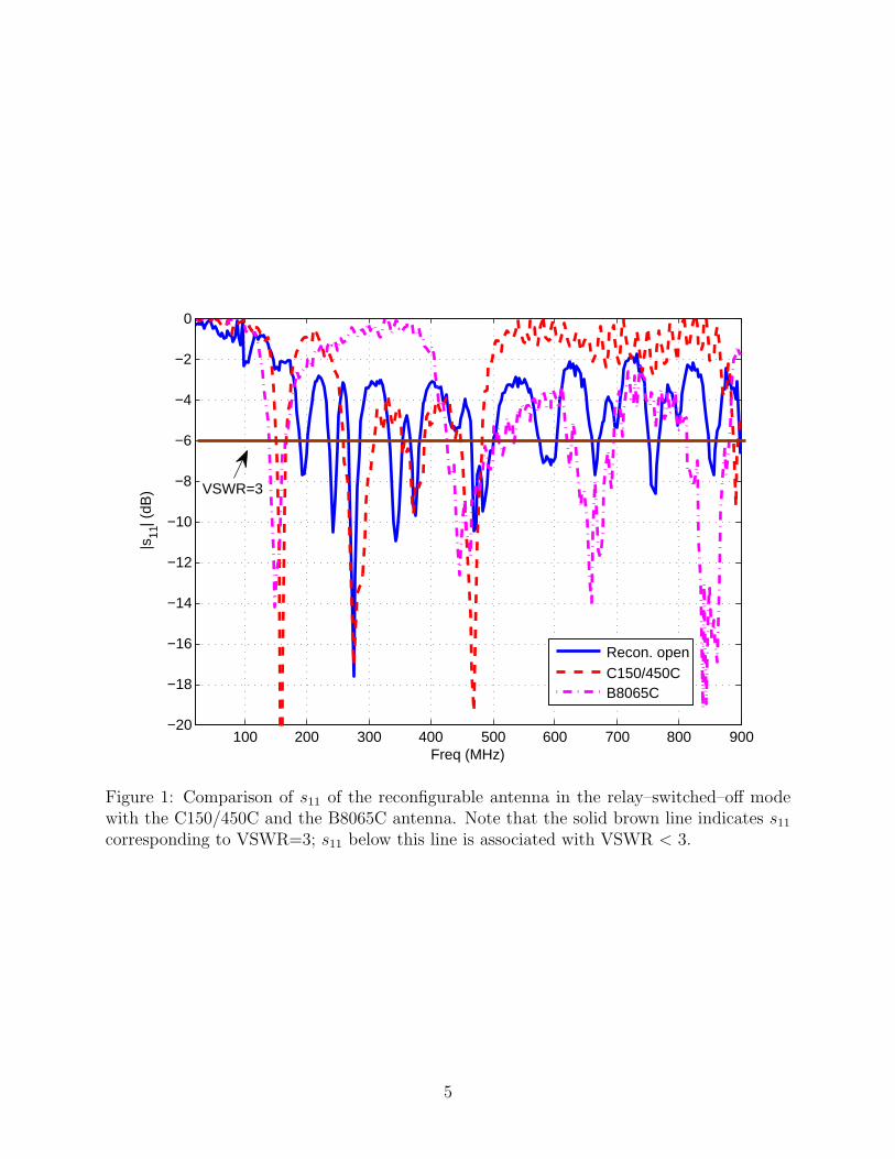
band. The s11 of the reconfigurable antenna in the relay–switched–off mode is shown in
Figure 1. Also shown in the figure is the s11 measured for the C150/450C and the B8065C
antenna. It is observed that at 851.535 MHz the s11 of the reconfigurable antenna is −7 dB
which is much larger than the s11 of −15 dB observed with the B8065C antenna. However,
a s11 value of −7 dB, i.e., a VSWR of 2.6 meets the requirement of VSWR < 3.
It is also observed from Figure 1 that at 453.625 MHz the s11 for the reconfigurable
antenna is about −4 dB, which is larger than the s11 of −8 dB of the C150/450C antenna.
In order to improve the s11, the reconfigurable antenna is tuned using the tuner described
in [2]. We experimented with several stub lengths at several distances from the antenna
terminal. The antenna is connected to the tuner using a 97 cm long cable, as might be
required for a trunk mounted antenna to connect to a tuner located in the trunk. From our
experiment a 33.4 cm long open stub connected parallel to the line at a distance of 1.05 m
from the antenna terminal is eventually selected. This corresponds to the 8th switching
position in the tuner (see [2]), with the 1st switching position being the position closest to
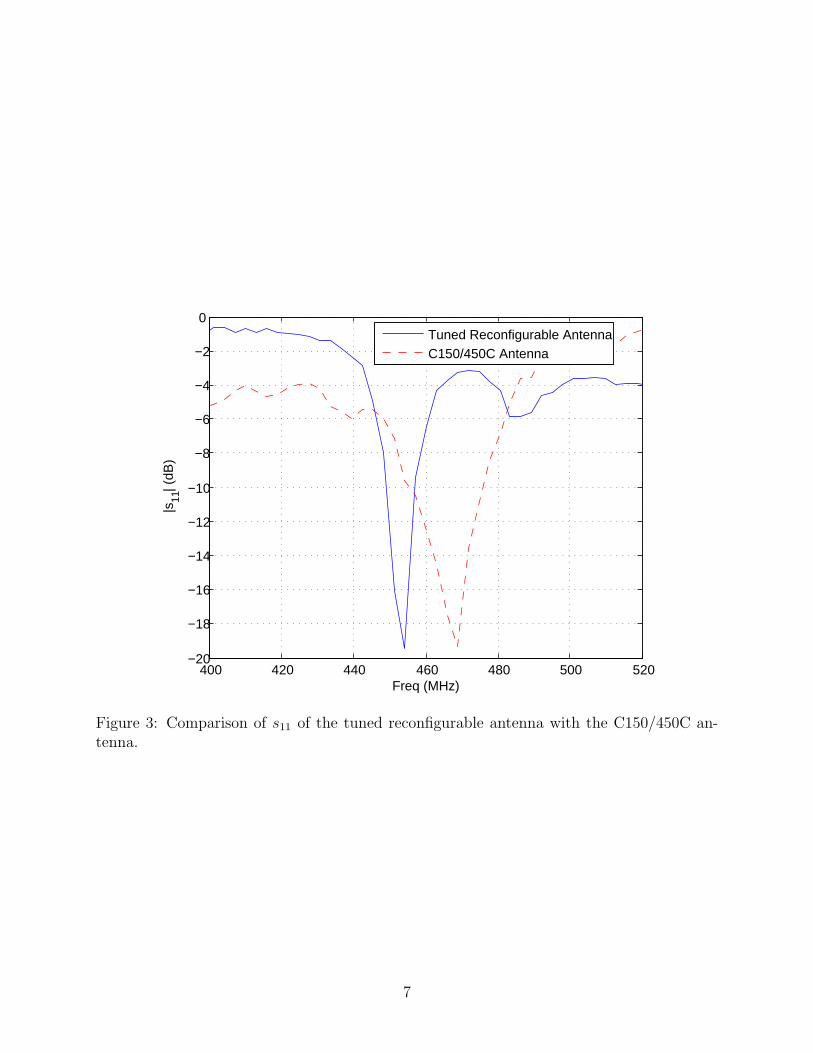
the antenna (shown in Figure 2). The results of s11 measurement are shown in Figure 3. The
measured s11 for the C150/450C antenna is also shown for comparison. It is observed that the
tuned reconfigurable antenna exhibits a s11 value of −18 dB at 453.625 MHz corresponding
to an improvement of 14 dB from the un–tuned antenna. Also, the performance of the tuned
antenna is better than the C150/450C antenna in the range 445–457 MHz and 484-520 MHz.
4
100 200 300 400 500 600 700 800 900−20
−18
−16
−14
−12
−10
−8
−6
−4
−2
0
|s11
| (dB
)
Freq (MHz)
Recon. openC150/450CB8065C
VSWR=3
Figure 1: Comparison of s11 of the reconfigurable antenna in the relay–switched–off modewith the C150/450C and the B8065C antenna. Note that the solid brown line indicates s11
corresponding to VSWR=3; s11 below this line is associated with VSWR < 3.
5
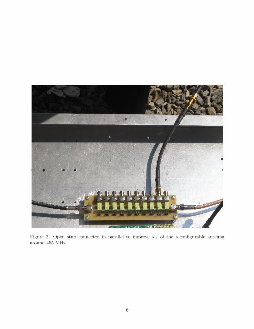
Figure 2: Open stub connected in parallel to improve s11 of the reconfigurable antennaaround 455 MHz.
6
400 420 440 460 480 500 520−20
−18
−16
−14
−12
−10
−8
−6
−4
−2
0
|s11
| (dB
)
Freq (MHz)
Tuned Reconfigurable AntennaC150/450C Antenna
Figure 3: Comparison of s11 of the tuned reconfigurable antenna with the C150/450C an-tenna.
7
The antenna tuner described in [2] proposed a closed loop for controlling the stub match-
ing based on the monitored VSWR. However, for the results presented in this report, we
didn’t use the closed loop. Our objective in this report is to investigate the usefulness
of tuning, and any stub matching that is observed to improve performance can easily be
incorporated with the closed loop antenna tuner in the final design.
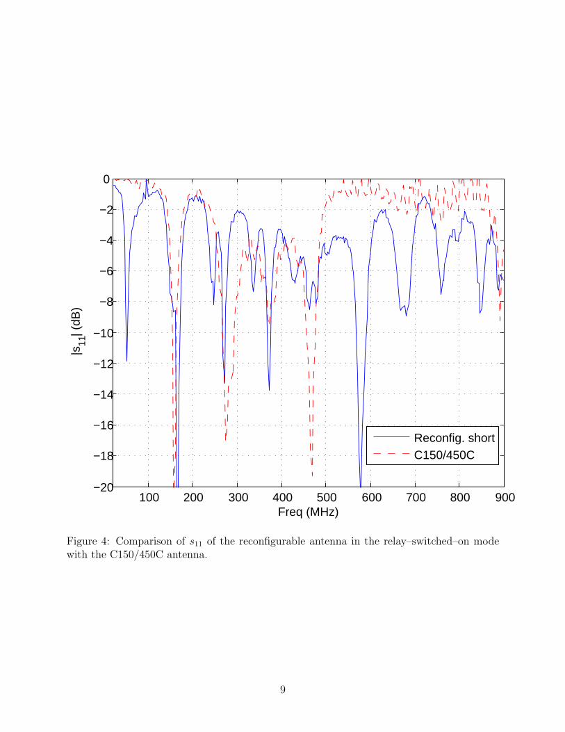
The s11 of the reconfigurable antenna in the relay switched on mode is shown in Figure 4.
Also shown in the figure is the s11 measured for the C150/450C antenna. It is observed
that at 155.535 MHz, the C150/450C antenna shows a s11 value of −11 dB; whereas the
reconfigurable antenna shows a s11 values of −8 dB, which is again small enough to protect
the transmitter from damage.
Thus, the reconfigurable antenna along with the tuner (if required) is comparable to
commercial LMR antennas from a transmit VSWR perspective. The next section investigates
the performance from a sensitivity perspective.
3 Comparison of Audio SNR
In this section we report the comparison of performance of the reconfigurable antenna with
the C150/450C and B8065C antenna in terms of the corresponding audio SNR. The exper-
imental setup for capturing the audio signal is shown in Figure 5. First, the reconfigurable
antenna and the B8065C antenna are simultaneously mounted above a ground plane (con-
structed of 3 aluminium panels as described in [1]) as shown in Figure 5. The reconfigurable
antenna is in the relay–switched–off mode in this case. Each of the antennas is connected
to an Icom receiver which communicates with a laptop. Software provided by the vendor
of Icom receiver runs on the laptop to record the audio signals. The receivers are tuned at
851.150 MHz and the on-the-air signals from Blacksburg Police are recorded. The recorded
audio signals are analyzed using the parametric estimation and subtraction (PE/S) method
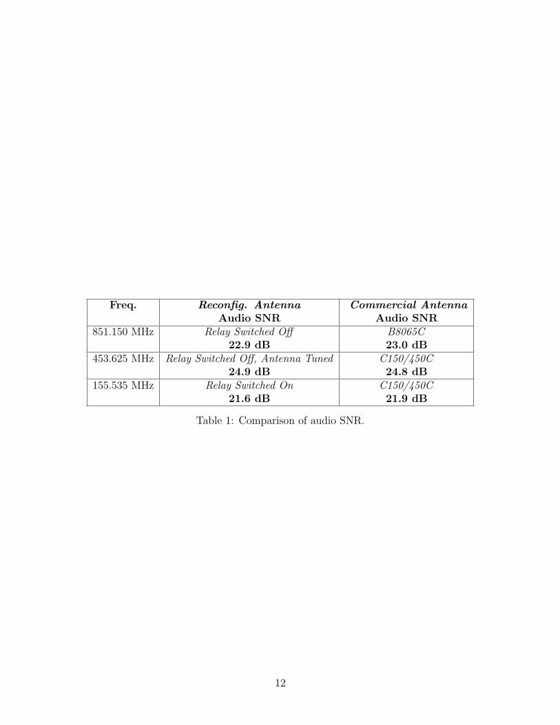
as described in [3], and the audio SNR is computed. The results are shown in Table 1. It is
8
100 200 300 400 500 600 700 800 900−20
−18
−16
−14
−12
−10
−8
−6
−4
−2
0
|s11
| (dB
)
Freq (MHz)
Reconfig. shortC150/450C
Figure 4: Comparison of s11 of the reconfigurable antenna in the relay–switched–on modewith the C150/450C antenna.
9
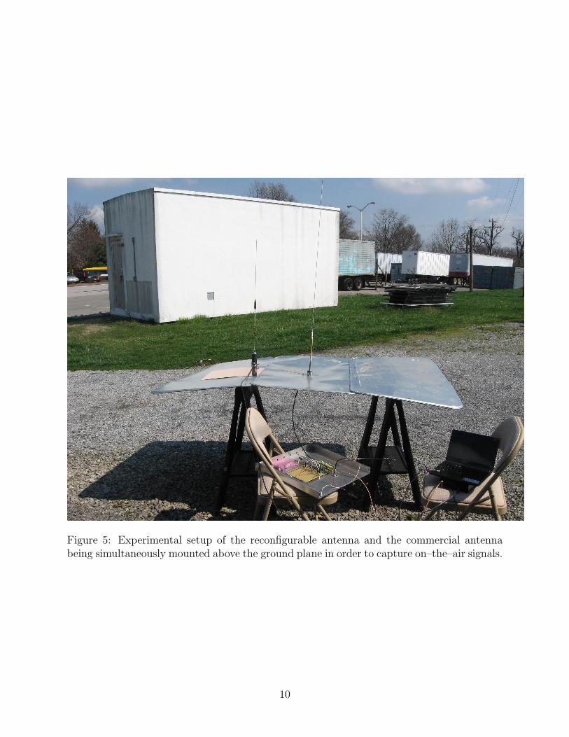
Figure 5: Experimental setup of the reconfigurable antenna and the commercial antennabeing simultaneously mounted above the ground plane in order to capture on–the–air signals.
10
observed that the audio SNR for the two antennas are comparable.
For the next set of measurements the B8065C antenna is replaced by the C150/450C
antenna, and the reconfigurable antenna is tuned using the stub as described in the previous
section. The receivers are then tuned at 453.625 MHz, and the audio signals are recorded.
The results of audio SNR calculation are shown in Table 1. It is observed that the audio
SNR with the tuned reconfigurable antenna is comparable to the C150/450C antenna.
For the last set of measurements, the reconfigurable antenna is set in the relay–switched–
on mode and the receivers are tuned at 155.535 MHz. The audio signals are recorded, and
the audio SNRs are analyzed. The results are again shown in Table 1. It is observed that
the audio SNRs are comparable.
Therefore, at all the three frequencies the reconfigurable antenna offers comparable sen-
sitivity to commercially available antennas.
4 Conclusion
The performance of the prototype reconfigurable antenna is compared with the Laird Tech-
nology’s C150/450C and B8065C antenna in terms of s11 and audio SNR. It is observed
that the reconfigurable antenna can be tuned to perform as good as or even better than
the C150/450C antenna in the UHF band. As mentioned, the tuning can be automatically
performed using a closed loop antenna tuner already developed for this application. Also,
the antenna in the relay–switched–off mode has comparable performance to the B8065C an-
tenna at 851.150 MHz; and in the relay–switched–on mode the performance at 155.535 MHz
is comparable to the C150/450C antenna. Therefore, the single reconfigurable antenna
of [1] (and [2]) along with a tuner (described in [2]) performs comparably to the band–
specific antennas, as are currently used in LMR antenna systems.
11
Freq. Reconfig. Antenna Commercial AntennaAudio SNR Audio SNR
851.150 MHz Relay Switched Off B8065C22.9 dB 23.0 dB
453.625 MHz Relay Switched Off, Antenna Tuned C150/450C24.9 dB 24.8 dB
155.535 MHz Relay Switched On C150/450C21.6 dB 21.9 dB
Table 1: Comparison of audio SNR.
12
References
[1] M. Harun, S. W. Ellingson, “A Prototype Simple Reconfigurable Antenna for the Multi-
band LMR Antenna System ”, Project Report, Virginia Polytechnic Inst. & State U.,
April 4, 2012.
[2] S. Ellingson, ““Phase II” Design for a Multiband LMR Antenna System,” Project
Report No. 18, Virginia Polytechnic Inst. & State U., August 30, 2011. [online]
http://www.ece.vt.edu/swe/asmr/.
[3] A. Kumar, S.W. Ellingson, “Characterization of LMR Analog FM Audio Quality Using
PL Tone Analysis”, Project Report No. 15, Virginia Polytechnic Inst. & State U., July
25, 2011. [online] http://www.ece.vt.edu/swe/asmr/.
13