Embed Size (px)
Citation preview
Reconfigurable, Intelligently-Adaptive, Communication
System, an SDR Platform
Rigoberto J. Roche∗
NASA Glenn Research Center, Cleveland, OH, 44135
Mary Jo Shalkhauser †
NASA Glenn Research Center, Cleveland, OH, 44135
Joseph P. Hickey ‡
ZIN Technologies, Inc., Brook Park, OH
Janette C. Briones§
NASA Glenn Research Center, Cleveland, OH, 44135
The Space Telecommunications Radio System (STRS) provides a common, consistentframework to abstract the application software from the radio platform hardware. STRSaims to reduce the cost and risk of using complex, configurable and reprogrammable radiosystems across NASA missions. The NASA Glenn Research Center (GRC) team madea software defined radio (SDR) platform STRS compliant by adding an STRS operatingenvironment and a field programmable gate array (FPGA) wrapper, capable of implement-ing each of the platforms interfaces, as well as a test waveform to exercise those interfaces.This effort serves to provide a framework toward waveform development onto an STRScompliant platform to support future space communication systems for advanced explo-ration missions. The use of validated STRS compliant applications provides tested codewith extensive documentation to potentially reduce risk, cost and effort in developmentof space-deployable SDRs. This paper discusses the advantages of STRS, the integrationof STRS onto a Reconfigurable, Intelligently-Adaptive, Communication System (RIACS)SDR platform, and the test waveform and wrapper development efforts. The paper em-phasizes the infusion of the STRS Architecture onto the RIACS platform for potential usein next generation flight system SDRs for advanced exploration missions.
I. Introduction
The STRS architecture is a framework for the design, development, operation and upgrade of space-basedsoftware defined radios. This framework aims to create a standard interface between the operating envi-
ronment and a waveform application by using the Application Programmer Interface (API) while leveragingthe constrained resources of space SDRs. This document provides a detailed description of the developmentprocess and tools, coding and implementation approaches, and performance benchmarks and tradeoffs forimplementing a version of STRS onto a prototype SDR. The paper presents descriptions of how the ra-dio operates, the internal APIs, the configuration files, constraints and lessons learned, and provides theexecution process. The intended audience of this document is the developers of software architectures for
∗Computer Engineer, Information and Signal Processing Branch, MS-54-1, Non-member.†Electronics Engineer, Avionics Branch, MS-309-2, Non-member‡Software Engineer, ZIN Technologies, Inc., Non-member.§Computer Engineer, Information and Signal Processing Branch, MS-54-1, Non-member.
1 of 10
American Institute of Aeronautics and Astronautics
https://ntrs.nasa.gov/search.jsp?R=20170001411 2020-04-24T11:54:12+00:00Z
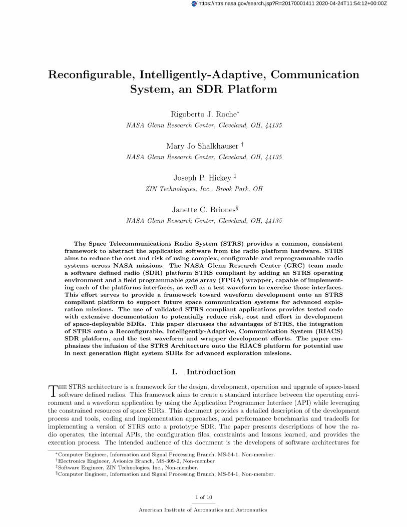
SDR platforms, especially aero and space SDRs. The integrated power, avionics and software (iPAS) STRSRadio was implemented on RIACS platform, currently being used for radio development at NASA JohnsonSpace Center (JSC). The platform consists of a Xilinx ML605 Virtex-6 FPGA board, an Analog DevicesFMCOMMS1-EBZ RF transceiver board, and an Embedded PC (Aiomtek eBox 620-110-FL) running theUbuntu 12.4 operating system. Fig 1 shows the RIACS platform hardware.
Figure 1. RIACS Platform.
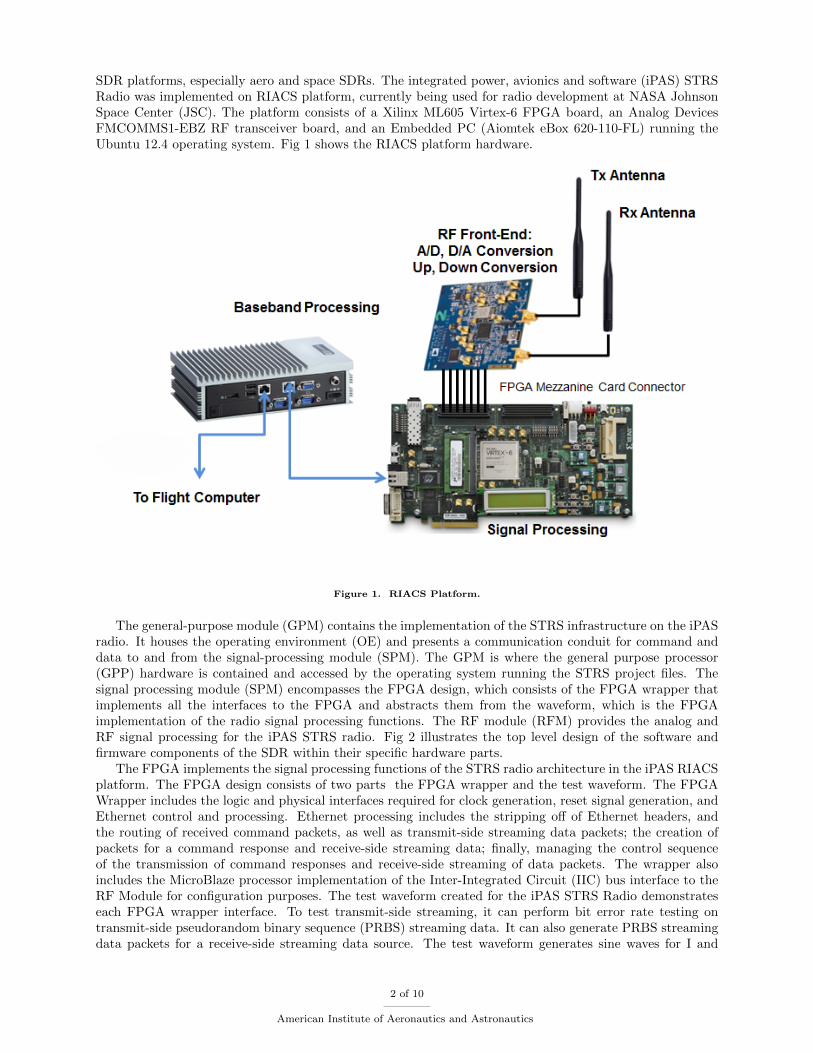
The general-purpose module (GPM) contains the implementation of the STRS infrastructure on the iPASradio. It houses the operating environment (OE) and presents a communication conduit for command anddata to and from the signal-processing module (SPM). The GPM is where the general purpose processor(GPP) hardware is contained and accessed by the operating system running the STRS project files. Thesignal processing module (SPM) encompasses the FPGA design, which consists of the FPGA wrapper thatimplements all the interfaces to the FPGA and abstracts them from the waveform, which is the FPGAimplementation of the radio signal processing functions. The RF module (RFM) provides the analog andRF signal processing for the iPAS STRS radio. Fig 2 illustrates the top level design of the software andfirmware components of the SDR within their specific hardware parts.
The FPGA implements the signal processing functions of the STRS radio architecture in the iPAS RIACSplatform. The FPGA design consists of two parts the FPGA wrapper and the test waveform. The FPGAWrapper includes the logic and physical interfaces required for clock generation, reset signal generation, andEthernet control and processing. Ethernet processing includes the stripping off of Ethernet headers, andthe routing of received command packets, as well as transmit-side streaming data packets; the creation ofpackets for a command response and receive-side streaming data; finally, managing the control sequenceof the transmission of command responses and receive-side streaming of data packets. The wrapper alsoincludes the MicroBlaze processor implementation of the Inter-Integrated Circuit (IIC) bus interface to theRF Module for configuration purposes. The test waveform created for the iPAS STRS Radio demonstrateseach FPGA wrapper interface. To test transmit-side streaming, it can perform bit error rate testing ontransmit-side pseudorandom binary sequence (PRBS) streaming data. It can also generate PRBS streamingdata packets for a receive-side streaming data source. The test waveform generates sine waves for I and
2 of 10
American Institute of Aeronautics and Astronautics
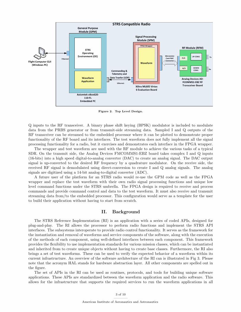
Figure 2. Top Level Design.
Q inputs to the RF transceiver. A binary phase shift keying (BPSK) modulator is included to modulatedata from the PRBS generator or from transmit-side streaming data. Sampled I and Q outputs of theRF transceiver can be streamed to the embedded processor where it can be plotted to demonstrate properfunctionality of the RF board and its interfaces. The test waveform does not fully implement all the signalprocessing functionality for a radio, but it exercises and demonstrates each interface in the FPGA wrapper.
The wrapper and test waveform are used with the RF module to achieve the various tasks of a typicalSDR. On the transmit side, the Analog Devices FMCOMMS1-EBZ board takes complex I and Q inputs(16-bits) into a high speed digital-to-analog converter (DAC) to create an analog signal. The DAC outputsignal is up-converted to the desired RF frequency by a quadrature modulator. On the receive side, thereceived RF signal is demodulated using direct-conversion to create I and Q analog signals. The analogsignals are digitized using a 14-bit analog-to-digital converter (ADC).
A future user of the platform for an STRS radio would re-use the GPM code as well as the FPGAwrapper and replace the test waveform with their own radio signal processing functions and unique lowlevel command functions under the STRS umbrella. The FPGA design is required to receive and processcommands and provide command control and data to the test waveform. It must also receive and transmitstreaming data from/to the embedded processor. This configuration would serve as a template for the userto build their application without having to start from scratch.
II. Background
The STRS Reference Implementation (RI) is an application with a series of coded APIs, designed forplug-and-play. The RI allows the processor to perform radio functions and implement the STRS APIinterfaces. The subsystems interoperate to provide radio control functionality. It serves as the framework forthe instantiation and removal of waveforms and service components of the software, along with the executionof the methods of each component, using well-defined interfaces between each component. This frameworkprovides the flexibility to use implementation standards for various mission classes, which can be instantiatedand inherited from to create unique objects without having to create base classes. Furthermore, the RI alsobrings a set of test waveforms. These can be used to verify the expected behavior of a waveform within itscurrent infrastructure. An overview of the software architecture of the RI can is illustrated in Fig 3. Pleasenote that the acronym HAL stands for hardware abstraction layer. All other components are spelled out inthe figure.
The set of APIs in the RI can be used as routines, protocols, and tools for building unique softwareapplications. These APIs are standardized between the waveform application and the radio software. Thisallows for the infrastructure that supports the required services to run the waveform applications in all
3 of 10
American Institute of Aeronautics and Astronautics
Figure 3. Architecture Overview of the Reference Implementation.1
systems with the same standard interfaces, with minimal rework. These APIs are specified by the architectureto separate the waveform from the operating environment (OE), thus making the waveform portable.1 STRSAPIs provide a consistent interface for waveform and system management, timing, and logical device control.They allow applications to be instantiated and use platform services to enable streamlined communicationbetween the waveform, other SDR applications and system components.
The iPAS hardware platform provides the component and interfaces used by the RI to implement STRSon the system, allowing designers to create waveform components written in either C or C++. Additionally,STRS configuration files contain platform and waveform specific information, which coupled with standard-ized interface allow for customization of installed waveforms, without hindering portability.
III. Implementation
A. Software Development on the GPP
The software design for the iPAS SDR is implemented on an Aiomtek eBox 620-110-FL. which containsan AMD G-Series APU T56N 1.65 GHz processor. This PC has a 200 GB hard drive and is running Ubuntu12.04 LTS operating system. The development tools used for this GPM design are: Eclipse Indigo with allinternal compilers for C/C++, as well as other Linux tools, such as GNU Make, and Bash Scripting.
The STRS command infrastructure on the iPAS radio is implemented on the GPM. Using the RI as abase framework, an interface was constructed, that would work with the iPAS SDR. The RI functionality wasmodified and a sample waveform was added. This method reduced code duplication and allowed the teamto work with a known set of APIs that were previously reviewed and approved for release. A communicationconduit for command and data transfer to the SPM was created with the RI as a basis. This conduit workswith a command routing structure, in which commands are entered via the flight computer simulator (FCS).The Command and Control Module (CCM) converts the commands into calls to the STRS standard APIwithin the OE. The OE controls the waveform application as requested. Then the waveform applicationreplies to the commands back to the OE, which handles the responses and routes them via the CCM backto FCS. The basic functionality of this conduit is illustrated in Fig 4.
The development group at NASA Johnson Space Center uses this specific GPM hardware as their devel-opment platform. Therefore, in order to make the GRC system work with their hardware, the GRC teamdeveloped on the same type of unit. The STRS Architecture running on the GPP hardware can perform
4 of 10
American Institute of Aeronautics and Astronautics
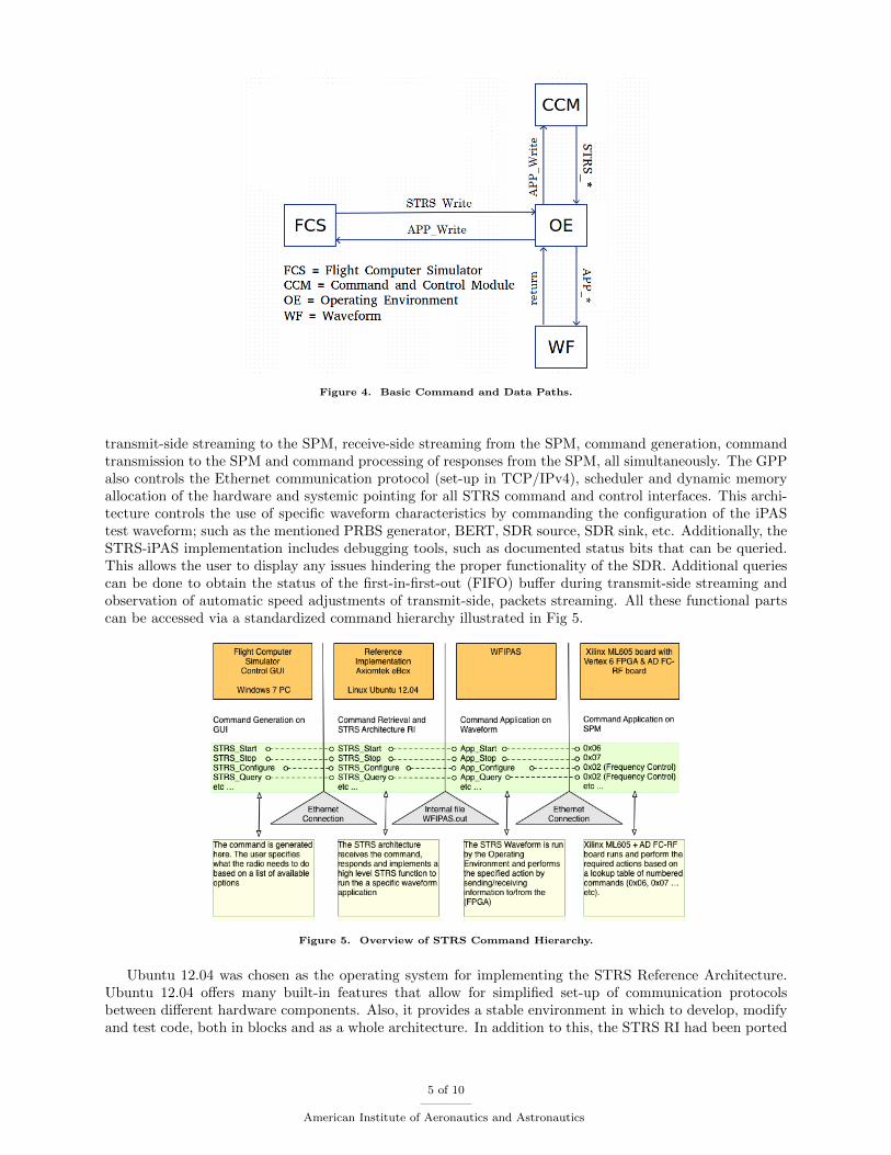
Figure 4. Basic Command and Data Paths.
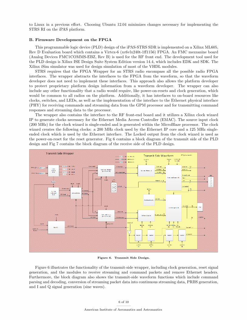
transmit-side streaming to the SPM, receive-side streaming from the SPM, command generation, commandtransmission to the SPM and command processing of responses from the SPM, all simultaneously. The GPPalso controls the Ethernet communication protocol (set-up in TCP/IPv4), scheduler and dynamic memoryallocation of the hardware and systemic pointing for all STRS command and control interfaces. This archi-tecture controls the use of specific waveform characteristics by commanding the configuration of the iPAStest waveform; such as the mentioned PRBS generator, BERT, SDR source, SDR sink, etc. Additionally, theSTRS-iPAS implementation includes debugging tools, such as documented status bits that can be queried.This allows the user to display any issues hindering the proper functionality of the SDR. Additional queriescan be done to obtain the status of the first-in-first-out (FIFO) buffer during transmit-side streaming andobservation of automatic speed adjustments of transmit-side, packets streaming. All these functional partscan be accessed via a standardized command hierarchy illustrated in Fig 5.
Figure 5. Overview of STRS Command Hierarchy.
Ubuntu 12.04 was chosen as the operating system for implementing the STRS Reference Architecture.Ubuntu 12.04 offers many built-in features that allow for simplified set-up of communication protocolsbetween different hardware components. Also, it provides a stable environment in which to develop, modifyand test code, both in blocks and as a whole architecture. In addition to this, the STRS RI had been ported
5 of 10
American Institute of Aeronautics and Astronautics
to Linux in a previous effort. Choosing Ubuntu 12.04 minimizes changes necessary for implementing theSTRS RI on the iPAS platform.
B. Firmware Development on the FPGA
This programmable logic device (PLD) design of the iPAS-STRS SDR is implemented on a Xilinx ML605,Rev D Evaluation board which contains a Virtex-6 (xc6vlx240t-1ff1156) FPGA. An FMC mezzanine board(Analog Devices FMC1COMMS-EBZ, Rev B) is used for the RF front end. The development tool used forthe PLD design is Xilinx ISE Design Suite System Edition version 14.4, which includes EDK and SDK. TheXilinx iSim simulator was used for design simulation of most of the VHDL modules.
STRS requires that the FPGA Wrapper for an STRS radio encompass all the possible radio FPGAinterfaces. The wrapper abstracts the interfaces to the FPGA from the waveform, so that the waveformdeveloper does not need to implement these interfaces. This approach also allows the platform developerto protect proprietary platform design information from a waveform developer. The wrapper can alsoinclude any other functionality that a radio would require, like power-on-resets and clock generation, whichwould be common to all radios on the platform. Additionally, it has interfaces to on-board resources likeclocks, switches, and LEDs, as well as the implementation of the interface to the Ethernet physical interface(PHY) for receiving commands and streaming data from the GPM processor and for transmitting commandresponses and streaming data to the processor.
The wrapper also contains the interface to the RF front-end board and it utilizes a Xilinx clock wizardIP to generate clocks necessary for the Ethernet Media Access Controller (EMAC). The source input clock(200 MHz) for the clock wizard is single-ended and is generated within the MicroBlaze processor. The clockwizard creates the following clocks: a 200 MHz clock used by the Ethernet IP core and a 125 MHz single-ended clock which is used by the Ethernet interface. The Locked output from the clock wizard is used asthe power-on-reset for the reset generator. Fig 6 contains a block diagram of the transmit side of the PLDdesign and Fig 7 contains the block diagram of the receive side of the PLD design.
Figure 6. Transmit Side Design.
Figure 6 illustrates the functionality of the transmit-side wrapper, including clock generation, reset signalgeneration, and the modules to receive streaming and command packets and remove Ethernet headers.Furthermore, the block diagram also shows the transmit-side waveform functions which include commandparsing and decoding, conversion of streaming packet data into continuous streaming data, PRBS generation,and I and Q signal generation (sine waves).
6 of 10
American Institute of Aeronautics and Astronautics
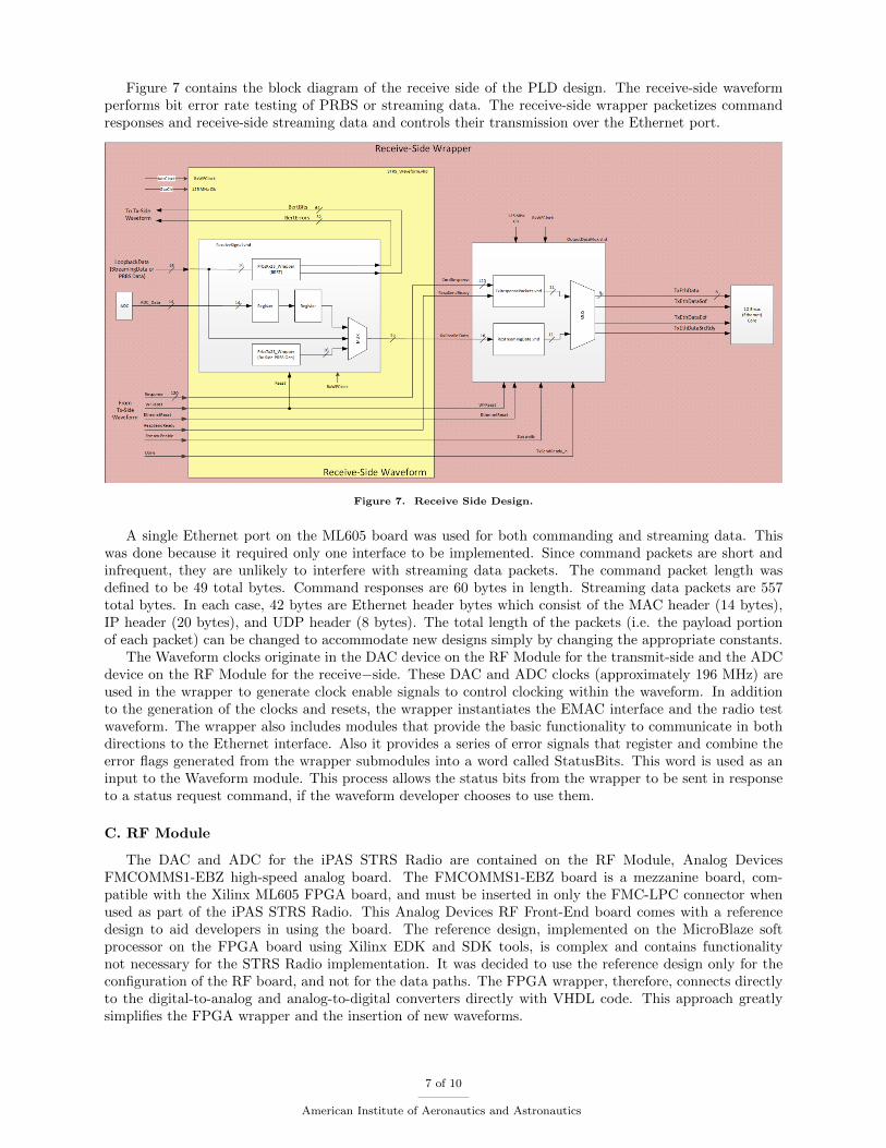
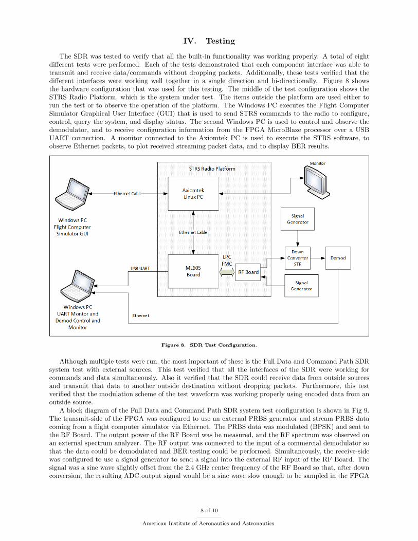
Figure 7 contains the block diagram of the receive side of the PLD design. The receive-side waveformperforms bit error rate testing of PRBS or streaming data. The receive-side wrapper packetizes commandresponses and receive-side streaming data and controls their transmission over the Ethernet port.
Figure 7. Receive Side Design.
A single Ethernet port on the ML605 board was used for both commanding and streaming data. Thiswas done because it required only one interface to be implemented. Since command packets are short andinfrequent, they are unlikely to interfere with streaming data packets. The command packet length wasdefined to be 49 total bytes. Command responses are 60 bytes in length. Streaming data packets are 557total bytes. In each case, 42 bytes are Ethernet header bytes which consist of the MAC header (14 bytes),IP header (20 bytes), and UDP header (8 bytes). The total length of the packets (i.e. the payload portionof each packet) can be changed to accommodate new designs simply by changing the appropriate constants.
The Waveform clocks originate in the DAC device on the RF Module for the transmit-side and the ADCdevice on the RF Module for the receive−side. These DAC and ADC clocks (approximately 196 MHz) areused in the wrapper to generate clock enable signals to control clocking within the waveform. In additionto the generation of the clocks and resets, the wrapper instantiates the EMAC interface and the radio testwaveform. The wrapper also includes modules that provide the basic functionality to communicate in bothdirections to the Ethernet interface. Also it provides a series of error signals that register and combine theerror flags generated from the wrapper submodules into a word called StatusBits. This word is used as aninput to the Waveform module. This process allows the status bits from the wrapper to be sent in responseto a status request command, if the waveform developer chooses to use them.
C. RF Module
The DAC and ADC for the iPAS STRS Radio are contained on the RF Module, Analog DevicesFMCOMMS1-EBZ high-speed analog board. The FMCOMMS1-EBZ board is a mezzanine board, com-patible with the Xilinx ML605 FPGA board, and must be inserted in only the FMC-LPC connector whenused as part of the iPAS STRS Radio. This Analog Devices RF Front-End board comes with a referencedesign to aid developers in using the board. The reference design, implemented on the MicroBlaze softprocessor on the FPGA board using Xilinx EDK and SDK tools, is complex and contains functionalitynot necessary for the STRS Radio implementation. It was decided to use the reference design only for theconfiguration of the RF board, and not for the data paths. The FPGA wrapper, therefore, connects directlyto the digital-to-analog and analog-to-digital converters directly with VHDL code. This approach greatlysimplifies the FPGA wrapper and the insertion of new waveforms.
7 of 10
American Institute of Aeronautics and Astronautics
IV. Testing
The SDR was tested to verify that all the built-in functionality was working properly. A total of eightdifferent tests were performed. Each of the tests demonstrated that each component interface was able totransmit and receive data/commands without dropping packets. Additionally, these tests verified that thedifferent interfaces were working well together in a single direction and bi-directionally. Figure 8 showsthe hardware configuration that was used for this testing. The middle of the test configuration shows theSTRS Radio Platform, which is the system under test. The items outside the platform are used either torun the test or to observe the operation of the platform. The Windows PC executes the Flight ComputerSimulator Graphical User Interface (GUI) that is used to send STRS commands to the radio to configure,control, query the system, and display status. The second Windows PC is used to control and observe thedemodulator, and to receive configuration information from the FPGA MicroBlaze processor over a USBUART connection. A monitor connected to the Axiomtek PC is used to execute the STRS software, toobserve Ethernet packets, to plot received streaming packet data, and to display BER results.
Figure 8. SDR Test Configuration.
Although multiple tests were run, the most important of these is the Full Data and Command Path SDRsystem test with external sources. This test verified that all the interfaces of the SDR were working forcommands and data simultaneously. Also it verified that the SDR could receive data from outside sourcesand transmit that data to another outside destination without dropping packets. Furthermore, this testverified that the modulation scheme of the test waveform was working properly using encoded data from anoutside source.
A block diagram of the Full Data and Command Path SDR system test configuration is shown in Fig 9.The transmit-side of the FPGA was configured to use an external PRBS generator and stream PRBS datacoming from a flight computer simulator via Ethernet. The PRBS data was modulated (BPSK) and sent tothe RF Board. The output power of the RF Board was be measured, and the RF spectrum was observed onan external spectrum analyzer. The RF output was connected to the input of a commercial demodulator sothat the data could be demodulated and BER testing could be performed. Simultaneously, the receive-sidewas configured to use a signal generator to send a signal into the external RF input of the RF Board. Thesignal was a sine wave slightly offset from the 2.4 GHz center frequency of the RF Board so that, after downconversion, the resulting ADC output signal would be a sine wave slow enough to be sampled in the FPGA
8 of 10
American Institute of Aeronautics and Astronautics
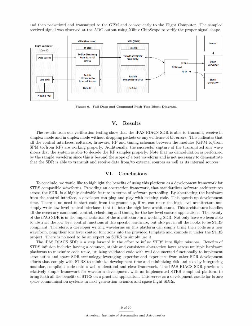
and then packetized and transmited to the GPM and consequently to the Flight Computer. The sampledreceived signal was observed at the ADC output using Xilinx ChipScope to verify the proper signal shape.
Figure 9. Full Data and Command Path Test Block Diagram.
V. Results
The results from our verification testing show that the iPAS RIACS SDR is able to transmit, receive insimplex mode and in duplex mode without dropping packets or any evidence of bit errors. This indicates thatall the control interfaces, software, firmware, RF and timing schemas between the modules (GPM to/fromSPM to/from RF) are working properly. Additionally, the successful capture of the transmitted sine waveshows that the system is able to decode the RF samples properly. Note that no demodulation is performedby the sample waveform since this is beyond the scope of a test waveform and is not necessary to demonstratethat the SDR is able to transmit and receive data from/to external sources as well as its internal sources.
VI. Conclusions
To conclude, we would like to highlight the benefits of using this platform as a development framework forSTRS compatible waveforms. Providing an abstraction framework, that standardizes software architecturesacross the SDR, is a highly desirable feature in terms of software portability. By abstracting the hardwarefrom the control interface, a developer can plug and play with existing code. This speeds up developmenttime. There is no need to start code from the ground up, if we can reuse the high level architecture andsimply write low level control interfaces that tie into the high level architecture. This architecture handlesall the necessary command, control, scheduling and timing for the low level control applications. The beautyof the iPAS SDR is in the implementation of the architecture in a working SDR. Not only have we been ableto abstract the low level control functions of this specific hardware, but also put in all the hooks to be STRScompliant. Therefore, a developer writing waveforms on this platform can simply bring their code as a newwaveform, plug their low level control functions into the provided template and compile it under the STRSproject. There is no need to be an expert on STRS to simply use it.
The iPAS RIACS SDR is a step forward in the effort to infuse STRS into flight missions. Benefits ofSTRS infusion include: having a common, stable and consistent abstraction layer across multiple hardwareplatforms to maximize code reuse, utilizing validated code with well documented functionally to implementaeronautics and space SDR technology, leveraging expertise and experience from other SDR developmentefforts that comply with STRS to minimize development time and minimizing risk and cost by integratingmodular, compliant code onto a well understood and clear framework. The iPAS RIACS SDR provides arelatively simple framework for waveform development with an implemented STRS compliant platform tobring forth all the benefits of STRS on a practical application. This serves as a development cradle for futurespace communication systems in next generation avionics and space flight SDRs.
9 of 10
American Institute of Aeronautics and Astronautics
Acknowledgments
The authors would like to acknowledge and thank the following individuals:
Louis M. Handler, for his help in the development of the base system (the original RI)Neil S. Adams, for his help in the development of the original external control interfaceRichard C, Reinhart, for his experienced guidance and clear vision to the direction of this workSandra K. Johnson, for her invaluable support and expert advice
References
1Variouse Authors, Space Telecommunications Radio System (STRS) Architecture Standard, NASA-STD-4009, NASAStandards Office, NASA Headquarters, Washington DC, 2014
10 of 10
American Institute of Aeronautics and Astronautics