Embed Size (px)
Citation preview
Reconfigurable Message Traffic Filters
MEng Individual Project
Deryck Arnold (daa07)Imperial College London
CID: 00469268
Supervisors:Professor Alexander L. Wolf
Professor Wayne Luk

Abstract
In this report we discuss the problem of string matching performance in content-based routing.We go on to describe and evaluate designs for reconfigurable hardware such as field-programmablegate arrays (FPGAs) that can be applied to solving this problem.
The hardware designs presented in this project are estimated to give a 37 times speed up and370 times power efficiency increase when running on a Xilinx Virtex6 FPGA over equivalent Cimplementations on a 2.40GHz dual-core Intel Core i3 processor.
We present a highly-extensible compiler tool that can convert abstract content-based forwardingrules into such designs for processing by further tools into working FPGA images.
Finally we discuss the potential applications and future developments of the work covered inthis project.

Acknowledgements
I would like to thank my supervisors Professor Alexander Wolf and Professor Wayne Luk forproviding guidance, enthusiasm and the expertise to encourage me through this project.
I would also like to thank my friends who have offered me help and assisted in proof-reading thisreport.
CONTENTS
Contents
1 Introduction 3
2 Related Work 52.1 Content-Based Networking and Forwarding . . . . . . . . . . . . . . . . . . . . . 6
2.1.1 Siena Fast Forwarding (SFF) . . . . . . . . . . . . . . . . . . . . . . . . . 62.1.2 Content-Based Matching using GPUs . . . . . . . . . . . . . . . . . . . . 7
2.2 String Matching - Software to Hardware . . . . . . . . . . . . . . . . . . . . . . . 82.2.1 Brute-Force (BF) Approach . . . . . . . . . . . . . . . . . . . . . . . . . . 82.2.2 Knuth-Morris-Pratt (KMP) . . . . . . . . . . . . . . . . . . . . . . . . . . 8
2.3 Content-Addressable Memory (CAM) . . . . . . . . . . . . . . . . . . . . . . . . 102.3.1 Simple CAM Comparator Architecture . . . . . . . . . . . . . . . . . . . . 102.3.2 Decoded CAM (DCAM) . . . . . . . . . . . . . . . . . . . . . . . . . . . . 102.3.3 Decoded Partial CAM (DpCAM) . . . . . . . . . . . . . . . . . . . . . . . 112.3.4 Ternary CAM (TCAM) . . . . . . . . . . . . . . . . . . . . . . . . . . . . 11
2.4 Reconfigurable Hardware . . . . . . . . . . . . . . . . . . . . . . . . . . . . . . . 12
3 Accelerating Matching 143.1 Node and Message Model . . . . . . . . . . . . . . . . . . . . . . . . . . . . . . . 153.2 Predicate Language . . . . . . . . . . . . . . . . . . . . . . . . . . . . . . . . . . . 16
3.2.1 Operators . . . . . . . . . . . . . . . . . . . . . . . . . . . . . . . . . . . . 163.2.2 Representation of Forwarding Rules . . . . . . . . . . . . . . . . . . . . . 17
3.3 Hardware Design Implementations . . . . . . . . . . . . . . . . . . . . . . . . . . 193.3.1 CAM Design . . . . . . . . . . . . . . . . . . . . . . . . . . . . . . . . . . 193.3.2 DCAM Design . . . . . . . . . . . . . . . . . . . . . . . . . . . . . . . . . 203.3.3 Addition of the lt and gt Operators . . . . . . . . . . . . . . . . . . . . . 21
3.4 C Implementation . . . . . . . . . . . . . . . . . . . . . . . . . . . . . . . . . . . 233.5 Automating Design Generation . . . . . . . . . . . . . . . . . . . . . . . . . . . . 24
3.5.1 Compiler Overview . . . . . . . . . . . . . . . . . . . . . . . . . . . . . . . 243.5.2 Rule Format . . . . . . . . . . . . . . . . . . . . . . . . . . . . . . . . . . 263.5.3 Validation of Compiler Output . . . . . . . . . . . . . . . . . . . . . . . . 263.5.4 The Users Perspective . . . . . . . . . . . . . . . . . . . . . . . . . . . . . 273.5.5 The Developers Perspective . . . . . . . . . . . . . . . . . . . . . . . . . . 28
4 Evaluation 314.1 Test Setup . . . . . . . . . . . . . . . . . . . . . . . . . . . . . . . . . . . . . . . . 32
4.1.1 C Implementation . . . . . . . . . . . . . . . . . . . . . . . . . . . . . . . 324.1.2 Verilog Implementation . . . . . . . . . . . . . . . . . . . . . . . . . . . . 33
4.2 Results . . . . . . . . . . . . . . . . . . . . . . . . . . . . . . . . . . . . . . . . . . 34
CONTENTS 1 Reconfigurable Message Traffic Filters
4.2.1 Per-character Timings . . . . . . . . . . . . . . . . . . . . . . . . . . . . . 344.2.2 Per-message Timings . . . . . . . . . . . . . . . . . . . . . . . . . . . . . . 344.2.3 Speedup . . . . . . . . . . . . . . . . . . . . . . . . . . . . . . . . . . . . . 37
4.3 Resource Utilisation . . . . . . . . . . . . . . . . . . . . . . . . . . . . . . . . . . 384.3.1 Power Requirements . . . . . . . . . . . . . . . . . . . . . . . . . . . . . . 384.3.2 Executable Size . . . . . . . . . . . . . . . . . . . . . . . . . . . . . . . . . 384.3.3 FPGA Utilisation . . . . . . . . . . . . . . . . . . . . . . . . . . . . . . . 39
4.4 Summary . . . . . . . . . . . . . . . . . . . . . . . . . . . . . . . . . . . . . . . . 41
5 Conclusions and Future Work 425.1 Applications and Future Work . . . . . . . . . . . . . . . . . . . . . . . . . . . . 44
5.1.1 Generalised Design . . . . . . . . . . . . . . . . . . . . . . . . . . . . . . . 445.1.2 As a Just-in-Time (JIT) Extension . . . . . . . . . . . . . . . . . . . . . . 44
1
Introduction
Since the conception of the internet, networked traffic over various protocols has been increasingdramatically, increasing the pressure on the systems that process and route this traffic to do soin a timely manner.
One such class of systems would be those involved in filtering out unwanted traffic, called networkintrusion detection systems, or NIDS for short. An analysis of the popular SNORT NIDS showedthat string matching was one of the major contributors to overall execution time, with 31% for 8.6million packets totalling more than one gigabyte of network data spent on string matching [12]. Itis for this reason that there have been many studies in increasing string matching efficiency, withmany focussing on exploiting the unique nature of hardware over software [22, 19, 16, 4, 5, 12].
Hardware implementations are known to be faster than equivalent software implementationsfor a variety of applications. This is due to the differing methods of operation [10]. One one sideof the scale there are application specific integrated circuits (ASICs) that are designed specificallyto solve a specific problem, however should that problem change, the chip needs to be redesignedand refabricated. A more flexible approach on the other side of the scale is a standard micro-processor that executes software instructions. By changing the instructions, a wide variety offunctionalities can be supported without requiring changes to the hardware itself. However, be-cause this microprocessor is required to look up instructions and decode them before ultimatelyexecuting them, operation can be much slower than a dedicated ASIC for the same task. Inthe gap between the two types exists the area of reconfigurable computing. Devices such asfield-programmable gate arrays (FPGAs) can be configured to exhibit different behaviours byprogramming the logic blocks that they consist of [3]. The flexibility and performance of recon-figurable computing makes it attractive for string searching, and in this paper we will be lookingto apply such techniques to a different, but similar area: content-based routing.
Content-based communication is a relatively new area, where messages sent over a content-based network aren’t routed based on a destination address, but rather by their content [8, 6].It is typically implemented as an overlay network in the application layer, and like NIDS, thereis emphasis on increasing the efficiency of routing through this network.
One such implementation that focussed on increasing the efficiency of forwarding messagesthrough a content-based network would be the Siena Fast Forwarding (SFF) algorithm. Itpresented a novel approach to forwarding by preprocessing messages to reduce overall processing
1. INTRODUCTION 3 Reconfigurable Message Traffic Filters
time of the message, as well as other optimisations in areas such as string matching [7].
In this report we focus on possible hardware designs that can increase the performance of content-based routing of messages with arbitrary string tags. We move onto the automatic generation ofthese designs, both in software and hardware. This moves the responsibility of converting rulesfrom the user of the system to a compiler. In doing so, this reduces the number of errors thatcan be introduced by building a design by hand and opens the rule synthesising process up tooptimisation.
Results from FPGA synthesis tools of outputted hardware designs estimate speedups to be,on average, 30 times faster than equivalent software implementations. While static designs arethe focus of this project, through the automation of design production, prototypes may be gen-erated quickly, providing the framework for future development in the field, capitalising on thesubstantial performance gains hardware can provide over software.
One possible application identified by this project involves using the design processes and softwaredevised here for just-in-time (JIT) extensions of existing algorithm implementations such as SFF.Another extension to this project discusses exploring the use of the software compiler to generateconfiguration data for a self-reconfiguring hardware implementation. A self-reconfiguring designwould fully exploit the highly reconfigurable nature of FPGAs, giving such an implementationan edge over an equivalent, but possibly faster ASIC design.
In summary, the contributions of this work are:
• High-performance hardware designs and techiniques for content-based multi-operator stringmatching in messages. Estimates put the speedup at 37 times and power-efficiency of 370times using a Xilinx Virtex6 FPGA over equivalent software running on a 2.40GHz dual-core Intel Core i3. [Section 3.3]
• Abstraction of intent from implementation, utilizing the following two methods:
– An easy-to-use language, simple-string forwarding rules (SSFR), to specify tag-basedmessage filters. [Section 3.5.2]
– An extensible compilation framework that can translate SSFR into targeted hardwareand software designs that are self-validating. [Section 3.5.5]
We will begin by setting the scene in part 2 with related background research. In part 3, we willlay the groundwork of the model and assumptions before describing the work undertaken. Part4 covers the test setup and results of benchmarking equivalent software implementations againsthardware designs. Finally, we discuss the benefits and disadvantages of our implementation, aswell as future paths that could be explored in part 5.
1. INTRODUCTION 4 Reconfigurable Message Traffic Filters
2
Related Work
Much work has been done in the fields of content-based networking, string matching and hard-ware acceleration of string matching. In order to put our work into context, we will summariserelated work in these fields in this chapter.
We will touch on the concept of content-based networking, before moving on to string matchingin software and how equivalent hardware representations have been implemented. Finally, wewill cover the exciting topic of reconfigurable hardware and what advances have been made inthe field.
2. RELATED WORK 5 Reconfigurable Message Traffic Filters
2.1. CONTENT-BASED NETWORKING AND FORWARDING
2.1 Content-Based Networking and Forwarding
A content-based network differs to the traditional IP network (though it may be built on top ofone) in that nodes aren’t assigned unique network addresses. Instead, each node advertises areceiver predicate, or r-predicate, which specifies what messages sent over the network the nodeis interested in receiving [8]. An r-predicate doesn’t necessarily correspond to what the nodeitself is interested in, but rather the node, may be part of a path to a node that is ultimatelyinterested in messages matching the r-predicate. This allows messages to be routed through anetwork from various publishers to interested subscribers without requiring knowledge about theindividual subscribers themselves, just their interests which are propagated through the network.The following is an example of an r-predicate:
first = john ∧ last = smith ∨ first = mary ∧ title = mrs. ∨ title = sir
Each routing node would maintain a set, or forwarding table of these r-predicates associatedwith each interface it can forward messages to. If an incoming message matches an r-predicatestored in this table, it is forwarded to the interface the predicate is associated with. Thus, thisforwarding function can be represented as the following [6]:
forward(m) = {i ∈ I : m matches FwdTable(i)} where FwdTable : I → P
With large numbers of subscribers, these forwarding tables can get quite large, which can increasefiltering and forwarding speed [8]. Therefore emphasis is placed on reducing the size of theseforwarding tables, increasing the efficiency of the forwarding function and reducing the amountof unecessary traffic flowing through routers [6]. This is where we move onto implementationssuch as SFF, that will be discussed in 2.1.1.
2.1.1 Siena Fast Forwarding (SFF)
SFF was designed for fast forwarding of messages in a content based network. It was in particulardesigned to scale well to situations where there are large numbers of complex predicate filtersand high volumes of messages being generated by content publishers [7].
For a particular message, not all the forwarding rules needed to be applied, as some can befiltered out in an initial pre-processing step. Interfaces whose r-predicate attributes are notfound in a particular message can be ignored, therefore reducing the additional computationthat would have otherwise be spent on filtering on the interface’s constraints. This preprocessingstep can be performed a number of rounds, with the potential to remove an interface each round,however the number of rounds performed is dependent on the benefit attained against the timecost of the preprocessing itself. The higher the number of constraints, the more benefit is gainedfrom a large number of preprocessing rounds [7].
SFF uses a modified version of a ternary search tree (TST) to store search patterns and op-erators. Each node in a TST is comprised of a partitioning value, such as a character in a searchstring, as well as three pointers to further nodes in the TST. These pointers correspond to theless-than, equals and greater-than operators on this partitioning value [2].
The SFF implementation uses the same structure as the standard TST with the following ex-tensions:
• Multi-operator index for matching multiple operators.
2. RELATED WORK 6 Reconfigurable Message Traffic Filters
2.1. CONTENT-BASED NETWORKING AND FORWARDING
• Capability of matching partial strings for the prefix and substring operators.
• Greater than and less than constraints at TST leaf nodes are linked.
• Backtrack functions to transition between a partial match to the next closest completematch.
To match the substring and suffix operators, the TST search is performed starting at eachcharacter of an input string, with the prefix, equality, greater than and less than operator matchesdisabled past the first character [7].
2.1.2 Content-Based Matching using GPUs
A recent implementation of a content-based forwarder involved using CUDA to exploit the highlyparallel nature of GPUs [15]. In a similar way to SFF, filters for the CUDA Content-basedMatcher (CCM) are composed of constraints. In this particular implementation the constraintsare not stored in CPU memory but instead in the GPU memory. The CPU selects constraintsto filter on for a particular message and copies this data to the GPU, which spawns thousandsof threads to perform the matching process. After this process, the vector of interface matchesis copied back into the CPU memory space.
The results from this showed that the CCM implementation achieved up to a thirteen timesspeed up from a software SFF implementation running on a six-core CPU. The results give agood idea of the potential benefits that can be obtained from parallelising the matching processin content-based forwarding.
2. RELATED WORK 7 Reconfigurable Message Traffic Filters
2.2. STRING MATCHING - SOFTWARE TO HARDWARE
2.2 String Matching - Software to Hardware
Much work has been done in the field of string matching in both software and hardware. Becauseour filters are built from predicates over arbitrary string tags, we will cover a few methods ofstring searching in this section.
We will first cover simple methods of string searching in software, and how they have beenimplemented in hardware in order to give some background into the translation of softwarealgorithms into hardware.
2.2.1 Brute-Force (BF) Approach
The simplest and possibly the most obvious way of matching a string pattern P of length m insearch text S of length n would be to use the brute-force method.
BF in Software
Searching for P involves starting a fresh search at every index of S until a full match is found.This is shown in Listing 1.
Listing 1 BF algorithm
for i := 0 to n− 1 dofor j := 0 to m doif j = m thenreturn match;
end ifif (i + j) = n or S[i + j] 6= P [j] then
break;end if
end forend forreturn no match;
Due to the excess of character comparisons, for an arbitrary P of length m and arbitrary S oflength n the worst-case time complexity is O(mn), which is quite slow [9].
BF in Hardware
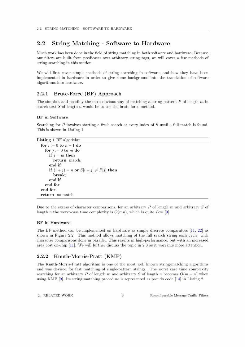
The BF method can be implemented on hardware as simple discrete comparators [11, 22] asshown in Figure 2.2. This method allows matching of the full search string each cycle, withcharacter comparisons done in parallel. This results in high-performance, but with an increasedarea cost on-chip [11]. We will further discuss the topic in 2.3 as it warrants more attention.
2.2.2 Knuth-Morris-Pratt (KMP)
The Knuth-Morris-Pratt algorithm is one of the most well known string-matching algorithmsand was devised for fast matching of single-pattern strings. The worst case time complexitysearching for an arbitrary P of length m and arbitrary S of length n becomes O(m + n) whenusing KMP [9]. Its string matching procedure is represented as pseudo code [14] in Listing 2.
2. RELATED WORK 8 Reconfigurable Message Traffic Filters
2.2. STRING MATCHING - SOFTWARE TO HARDWARE
Listing 2 KMP pattern matching algorithm
j := 1;k := 0;while j < m and k < n dowhile j > 0 and S[k] 6= P [j − 1] doj := next[j];
end whileend whileif j = m thenreturn match;
elsereturn no match;
end if
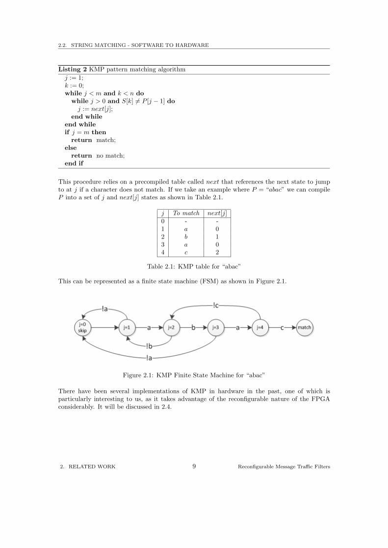
This procedure relies on a precompiled table called next that references the next state to jumpto at j if a character does not match. If we take an example where P = “abac” we can compileP into a set of j and next[j] states as shown in Table 2.1.
j To match next[j]0 - -1 a 02 b 13 a 04 c 2
Table 2.1: KMP table for “abac”
This can be represented as a finite state machine (FSM) as shown in Figure 2.1.
Figure 2.1: KMP Finite State Machine for “abac”
There have been several implementations of KMP in hardware in the past, one of which isparticularly interesting to us, as it takes advantage of the reconfigurable nature of the FPGAconsiderably. It will be discussed in 2.4.
2. RELATED WORK 9 Reconfigurable Message Traffic Filters
2.3. CONTENT-ADDRESSABLE MEMORY (CAM)
2.3 Content-Addressable Memory (CAM)
In typical RAM, data is mapped with addresses, requiring the user to supply an address toretrieve data. This is in contrast to content-addressable memory, or CAM, where the data issupplied, resulting in an address [16]. This CAM search is typically performed in one clock cy-cle, which makes it an ideal solution to bandwidth-heavy applications such as network intrusiondetection systems (NIDS) [4].
One of the downsides of the CAM design is its high power consumption. This is due to itshighly parallel nature, requiring a large amount of circuitry to be active every cycle, howeverpipelining techniques can reduce this [17, 18].
2.3.1 Simple CAM Comparator Architecture
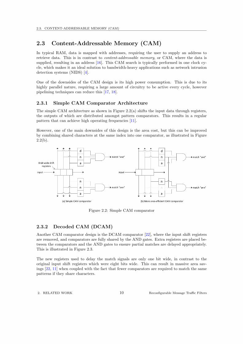
The simple CAM architecture as shown in Figure 2.2(a) shifts the input data through registers,the outputs of which are distributed amongst pattern comparators. This results in a regularpattern that can achieve high operating frequencies [11].
However, one of the main downsides of this design is the area cost, but this can be improvedby combining shared characters at the same index into one comparator, as illustrated in Figure2.2(b).
Figure 2.2: Simple CAM comparator
2.3.2 Decoded CAM (DCAM)
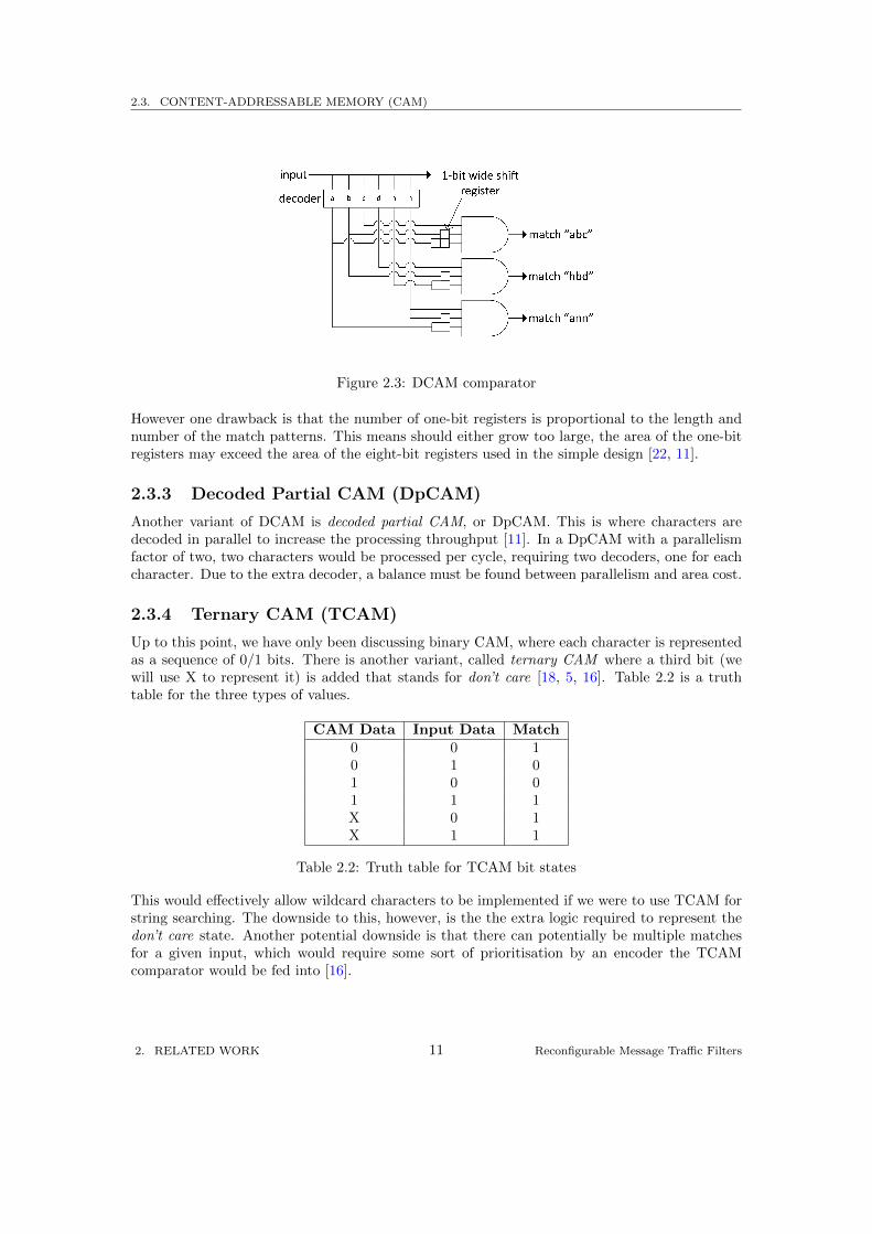
Another CAM comparator design is the DCAM comparator [22], where the input shift registersare removed, and comparators are fully shared by the AND gates. Extra registers are placed be-tween the comparators and the AND gates to ensure partial matches are delayed appropriately.This is illustrated in Figure 2.3.
The new registers used to delay the match signals are only one bit wide, in contrast to theoriginal input shift registers which were eight bits wide. This can result in massive area sav-ings [22, 11] when coupled with the fact that fewer comparators are required to match the samepatterns if they share characters.
2. RELATED WORK 10 Reconfigurable Message Traffic Filters
2.3. CONTENT-ADDRESSABLE MEMORY (CAM)
Figure 2.3: DCAM comparator
However one drawback is that the number of one-bit registers is proportional to the length andnumber of the match patterns. This means should either grow too large, the area of the one-bitregisters may exceed the area of the eight-bit registers used in the simple design [22, 11].
2.3.3 Decoded Partial CAM (DpCAM)
Another variant of DCAM is decoded partial CAM, or DpCAM. This is where characters aredecoded in parallel to increase the processing throughput [11]. In a DpCAM with a parallelismfactor of two, two characters would be processed per cycle, requiring two decoders, one for eachcharacter. Due to the extra decoder, a balance must be found between parallelism and area cost.
2.3.4 Ternary CAM (TCAM)
Up to this point, we have only been discussing binary CAM, where each character is representedas a sequence of 0/1 bits. There is another variant, called ternary CAM where a third bit (wewill use X to represent it) is added that stands for don’t care [18, 5, 16]. Table 2.2 is a truthtable for the three types of values.
CAM Data Input Data Match0 0 10 1 01 0 01 1 1X 0 1X 1 1
Table 2.2: Truth table for TCAM bit states
This would effectively allow wildcard characters to be implemented if we were to use TCAM forstring searching. The downside to this, however, is the the extra logic required to represent thedon’t care state. Another potential downside is that there can potentially be multiple matchesfor a given input, which would require some sort of prioritisation by an encoder the TCAMcomparator would be fed into [16].
2. RELATED WORK 11 Reconfigurable Message Traffic Filters
2.4. RECONFIGURABLE HARDWARE
2.4 Reconfigurable Hardware
Reconfigurable hardware is consists of configurable logic that is determined by data written intoconfiguration memory, which is typically SRAM. This allows the device logic to be changed bymodifying the data stored in the configuration memory.
Devices such as field-programmable gate arrays (FPGAs) are examples of reconfigurable hard-ware, and it is this reconfigurability that gives them an advantage over application-specifc inte-grated circuits (ASICs) for some applications.
This reconfigurability can be exploited at compile-time, i.e. before the device is operational,but to gain the full effectiveness of this paradigm, reconfiguration can be done at run-time. Thisallows the device to be configured with logic specific to the particular problem at hand. This isknown as instance-specific logic [21].
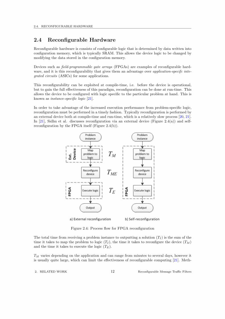
In order to take advantage of the increased execution performance from problem-specific logic,reconfiguration must be performed in a timely fashion. Typically reconfiguration is performed byan external device both at compile-time and run-time, which is a relatively slow process [20, 21].In [21], Sidhu et al. discusses reconfiguration via an external device (Figure 2.4(a)) and self-reconfiguration by the FPGA itself (Figure 2.4(b)).
Figure 2.4: Process flow for FPGA reconfiguration
The total time from receiving a problem instance to outputting a solution (TI) is the sum of thetime it takes to map the problem to logic (TI), the time it takes to reconfigure the device (TM )and the time it takes to execute the logic (TE).
TM varies depending on the application and can range from minutes to several days, however itis usually quite large, which can limit the effectiveness of reconfigurable computing [21]. Meth-
2. RELATED WORK 12 Reconfigurable Message Traffic Filters
2.4. RECONFIGURABLE HARDWARE
ods have been tried to reduce this problem, such as using CAD tools offline to create a generictemplate skeleton that is partially reconfigured at run time [13]. There is still the issue of TME
in this case if the partial reconfiguration is performed off-chip, as this is generally associated withthe speed of the connection between the host and the FPGA, as the delay may be too long formost real-time applications. This can be overcome through self-reconfiguration on chip.
Following on from 2.2.2, there have been several implementations of the KMP algorithm utilisingself-reconfiguration. One implementation was based on calculating the KMP pattern FSM andstoring the state table on internal block RAM [19]. It used an embedded soft-core processor toperform calculation of the various FSM states for string matching, and dedicated KMP logic toprocess text based on the FSM states stored in memory.
Another implementation exploited using multiple contexts to achieve self-reconfiguration [21].The FPGA would switch between contexts in order to calculate the KMP FSM and dedicatedlogic and to perform the actual string searching.
2. RELATED WORK 13 Reconfigurable Message Traffic Filters
3
Accelerating Matching
The initial implementations focussed primarily on attaining a working Verilog prototype im-plementation. These are covered in section 3.3. Alongside the Verilog, an equivalent softwareimplementation written in C was devised, which is described in section 3.4. The implementationswere developed on the assumptions and model outlined in section 3.1, and the predicate languagedefined in section 3.2.
The choice of C as the software implementation language was primarily down to the low-levelnature of the language. Since C does not come with any built-in garbage collection, or any otherunpredictable sources of overhead, benchmarks can be more representative of the capabilities ofsoftware.
For small sets of forwarding rules, this was adequate, as code can be translated easily by handfrom a rule specification. However for larger sets, writing the source code for forwarding rulescan be potentially time-consuming and error-prone. The solution was to implement a compilerthat could generate a software or hardware representation from a forwarding rule specificationinput. The design of the compiler written is detailed in 3.5.
3. ACCELERATING MATCHING 14 Reconfigurable Message Traffic Filters
3.1. NODE AND MESSAGE MODEL
3.1 Node and Message Model
In order to focus on the problem of implementing forwarding logic on hardware, it was importantto have a well-defined model with which we could base our solution on.
A general content based network is made up of many interconnected nodes. Each participantnode maintains a set of routing, or forwarding rules to forward messages from one point of thenetwork to another. The network may not be fully connected, so paths from any two nodes mayrun through intermediate nodes.
For the purpose of this project, we have ignored the structure of the network, the process ofdistributing forwarding rules between nodes and methods used to pass messages between nodes.This left us with the local forwarding processes occurring at an individual, arbitrary node in anarbitrary content-based network to form our model upon.
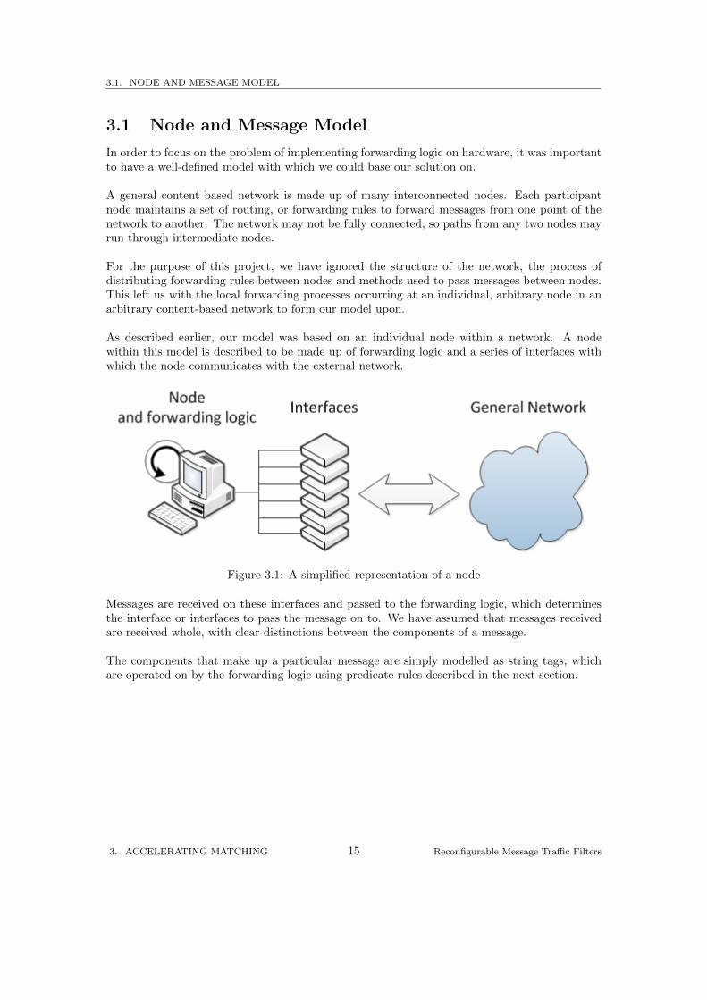
As described earlier, our model was based on an individual node within a network. A nodewithin this model is described to be made up of forwarding logic and a series of interfaces withwhich the node communicates with the external network.
Figure 3.1: A simplified representation of a node
Messages are received on these interfaces and passed to the forwarding logic, which determinesthe interface or interfaces to pass the message on to. We have assumed that messages receivedare received whole, with clear distinctions between the components of a message.
The components that make up a particular message are simply modelled as string tags, whichare operated on by the forwarding logic using predicate rules described in the next section.
3. ACCELERATING MATCHING 15 Reconfigurable Message Traffic Filters
3.2. PREDICATE LANGUAGE
3.2 Predicate Language
In our model, an interface is defined as a route to which a message may be forwarded to a node.The routing logic for each interface is described as a disjunction of filter predicates. Each filteris a conjunction of predicate terms, which are pairs of patterns and string operators. This issimilar to the SFF model, but with the omission of attribute keys and other datatypes. In orderto represent this model, we developed a predicate language that describes forwarding rules inthis environment in a concise manner.
To further describe this language, we will cover the different aspects in more detail in the followingsubsections.
3.2.1 Operators
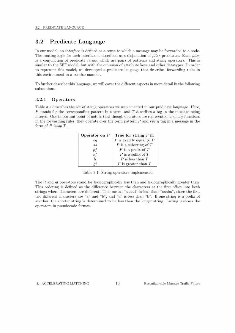
Table 3.1 describes the set of string operators we implemented in our predicate language. Here,P stands for the corresponding pattern in a term, and T describes a tag in the message beingfiltered. One important point of note is that though operators are represented as unary functionsin the forwarding rules, they operate over the term pattern P and every tag in a message in theform of P is-op T .
Operator on P True for string T if:eq P is exactly equal to Pss P is a substring of Tpf P is a prefix of Tsf P is a suffix of Tlt P is less than Tgt P is greater than T
Table 3.1: String operators implemented
The lt and gt operators stand for lexicographically less than and lexicographically greater than.This ordering is defined as the difference between the characters at the first offset into bothstrings where characters are different. This means “aaaad” is less than “aaaba”, since the firsttwo different characters are “a” and “b”, and “a” is less than “b”. If one string is a prefix ofanother, the shorter string is determined to be less than the longer string. Listing 3 shows theoperators in pseudocode format.
3. ACCELERATING MATCHING 16 Reconfigurable Message Traffic Filters
3.2. PREDICATE LANGUAGE
Listing 3 > and < algorithm
for i := 0 to min(length(str1), length(str2) doif (str1[i]− str2[i]) > 0 thenreturn str1 > str2;
else if (str1[i]− str2[i]) < 0 thenreturn str1 < str2;
end ifend forif (length(str1) > length(str2)) thenreturn str1 > str2;
else if (length(str1) < length(str2)) thenreturn str1 < str2;
elsereturn str1 = str2;
end if
3.2.2 Representation of Forwarding Rules
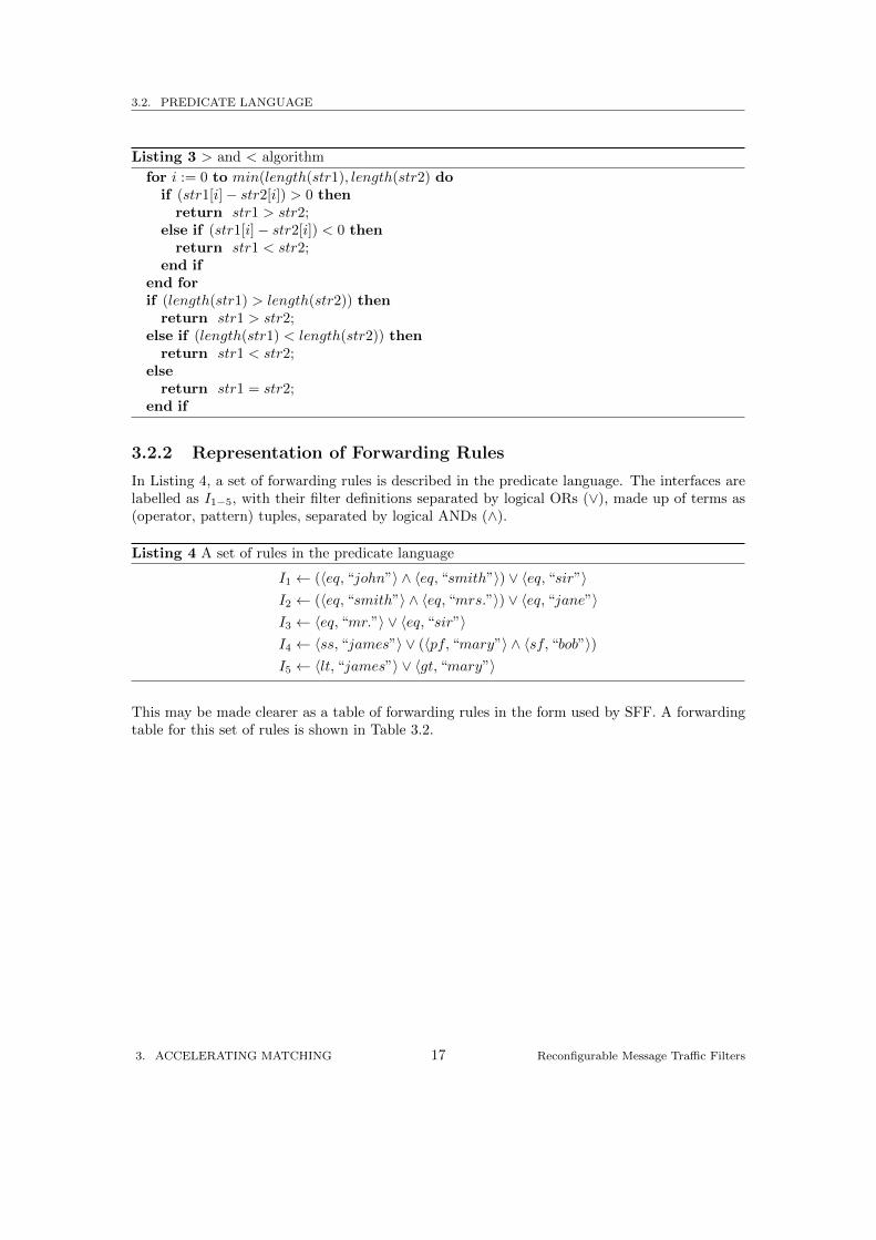
In Listing 4, a set of forwarding rules is described in the predicate language. The interfaces arelabelled as I1−5, with their filter definitions separated by logical ORs (∨), made up of terms as(operator, pattern) tuples, separated by logical ANDs (∧).
Listing 4 A set of rules in the predicate language
I1 ← (〈eq, “john”〉 ∧ 〈eq, “smith”〉) ∨ 〈eq, “sir”〉I2 ← (〈eq, “smith”〉 ∧ 〈eq, “mrs.”〉) ∨ 〈eq, “jane”〉I3 ← 〈eq, “mr.”〉 ∨ 〈eq, “sir”〉I4 ← 〈ss, “james”〉 ∨ (〈pf, “mary”〉 ∧ 〈sf, “bob”〉)I5 ← 〈lt, “james”〉 ∨ 〈gt, “mary”〉
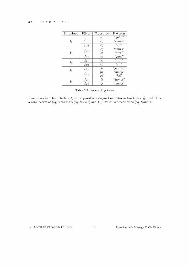
This may be made clearer as a table of forwarding rules in the form used by SFF. A forwardingtable for this set of rules is shown in Table 3.2.
3. ACCELERATING MATCHING 17 Reconfigurable Message Traffic Filters
3.2. PREDICATE LANGUAGE
Interface Filter Operator Pattern
I1f1,1
eq “john”eq “smith”
f1,2 eq “sir”
I2f2,1
eq “smith”eq “mrs.”
f2,2 eq “jane”
I3f3,1 eq “mr.”f3,2 eq “sir”
I4f4,1 ss “james”
f4,2pf “mary”sf “bob”
I5f5,1 lt “james”f5,2 gt “mary”
Table 3.2: Forwarding table
Here, it is clear that interface I2 is composed of a disjunction between two filters, f2,1, which isa conjunction of 〈eq, “smith”〉 ∧ 〈eq, “mrs.”〉 and f2,2, which is described as 〈eq, “jane”〉.
3. ACCELERATING MATCHING 18 Reconfigurable Message Traffic Filters
3.3. HARDWARE DESIGN IMPLEMENTATIONS
3.3 Hardware Design Implementations
Several iterations of hardware design were tried to find one that could implement all the desiredoperators in our predicate language. Emphasis was also placed on a regular design that wouldbe simple enough to be generated from a forwarding rule specification.
3.3.1 CAM Design
The initial approach was a simple CAM design of a set of forwarding rules. The eq, pf operatorscould easily be represented by a series of 8-bit comparators on each character of a pattern. Thelt and gt operators were not considered at this stage as the mechanics of these operators aredifferent to the other operators.
Characters from an input message tag would be shifted into a buffer the length of the largestpattern in the forwarding rule set plus one in bytes. If the tag was shorter than the shift buffer,the additional length would be padded with zero bytes.
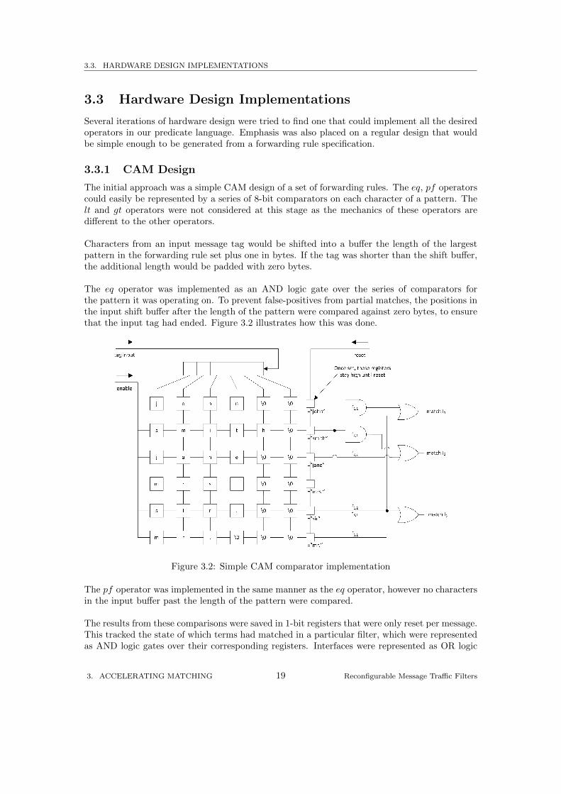
The eq operator was implemented as an AND logic gate over the series of comparators forthe pattern it was operating on. To prevent false-positives from partial matches, the positions inthe input shift buffer after the length of the pattern were compared against zero bytes, to ensurethat the input tag had ended. Figure 3.2 illustrates how this was done.
Figure 3.2: Simple CAM comparator implementation
The pf operator was implemented in the same manner as the eq operator, however no charactersin the input buffer past the length of the pattern were compared.
The results from these comparisons were saved in 1-bit registers that were only reset per message.This tracked the state of which terms had matched in a particular filter, which were representedas AND logic gates over their corresponding registers. Interfaces were represented as OR logic
3. ACCELERATING MATCHING 19 Reconfigurable Message Traffic Filters
3.3. HARDWARE DESIGN IMPLEMENTATIONS
gates over their corresponding filters.
Because of the simplicity of the design, it was very regular. Additional interfaces could beadded with extra OR gates over AND gate filters, with additional terms as extra 8-bit compara-tors.
However for larger or more diverse sets of rules, many comparators would need to be used.This is because each term used its own set of comparators, which could potentially increase thetotal area cost. The sf and ss operators weren’t very well suited to this design, as comparisonsonly occurred once the whole tag was shifted into the buffer.
3.3.2 DCAM Design
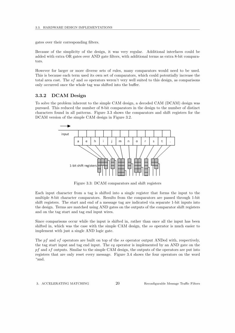
To solve the problem inherent to the simple CAM design, a decoded CAM (DCAM) design waspursued. This reduced the number of 8-bit comparators in the design to the number of distinctcharacters found in all patterns. Figure 3.3 shows the comparators and shift registers for theDCAM version of the simple CAM design in Figure 3.2.
Figure 3.3: DCAM comparators and shift registers
Each input character from a tag is shifted into a single register that forms the input to themultiple 8-bit character comparators. Results from the comparators are passed through 1-bitshift registers. The start and end of a message tag are indicated via separate 1-bit inputs intothe design. Terms are matched using AND gates on the outputs of the comparator shift registersand on the tag start and tag end input wires.
Since comparisons occur while the input is shifted in, rather than once all the input has beenshifted in, which was the case with the simple CAM design, the ss operator is much easier toimplement with just a single AND logic gate.
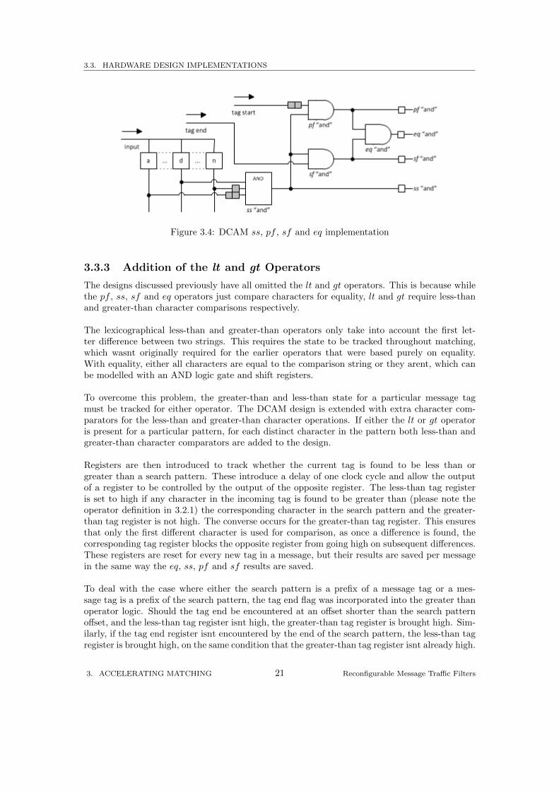
The pf and sf operators are built on top of the ss operator output ANDed with, respectively,the tag start input and tag end input. The eq operator is implemented by an AND gate on thepf and sf outputs. Similar to the simple CAM design, the outputs of the operators are put intoregisters that are only reset every message. Figure 3.4 shows the four operators on the word“and.
3. ACCELERATING MATCHING 20 Reconfigurable Message Traffic Filters
3.3. HARDWARE DESIGN IMPLEMENTATIONS
Figure 3.4: DCAM ss, pf , sf and eq implementation
3.3.3 Addition of the lt and gt Operators
The designs discussed previously have all omitted the lt and gt operators. This is because whilethe pf , ss, sf and eq operators just compare characters for equality, lt and gt require less-thanand greater-than character comparisons respectively.
The lexicographical less-than and greater-than operators only take into account the first let-ter difference between two strings. This requires the state to be tracked throughout matching,which wasnt originally required for the earlier operators that were based purely on equality.With equality, either all characters are equal to the comparison string or they arent, which canbe modelled with an AND logic gate and shift registers.
To overcome this problem, the greater-than and less-than state for a particular message tagmust be tracked for either operator. The DCAM design is extended with extra character com-parators for the less-than and greater-than character operations. If either the lt or gt operatoris present for a particular pattern, for each distinct character in the pattern both less-than andgreater-than character comparators are added to the design.
Registers are then introduced to track whether the current tag is found to be less than orgreater than a search pattern. These introduce a delay of one clock cycle and allow the outputof a register to be controlled by the output of the opposite register. The less-than tag registeris set to high if any character in the incoming tag is found to be greater than (please note theoperator definition in 3.2.1) the corresponding character in the search pattern and the greater-than tag register is not high. The converse occurs for the greater-than tag register. This ensuresthat only the first different character is used for comparison, as once a difference is found, thecorresponding tag register blocks the opposite register from going high on subsequent differences.These registers are reset for every new tag in a message, but their results are saved per messagein the same way the eq, ss, pf and sf results are saved.
To deal with the case where either the search pattern is a prefix of a message tag or a mes-sage tag is a prefix of the search pattern, the tag end flag was incorporated into the greater thanoperator logic. Should the tag end be encountered at an offset shorter than the search patternoffset, and the less-than tag register isnt high, the greater-than tag register is brought high. Sim-ilarly, if the tag end register isnt encountered by the end of the search pattern, the less-than tagregister is brought high, on the same condition that the greater-than tag register isnt already high.
3. ACCELERATING MATCHING 21 Reconfigurable Message Traffic Filters
3.3. HARDWARE DESIGN IMPLEMENTATIONS
Because the lt and gt operators result in the addition of both less-than and greater-than char-acter comparators, the equals character comparator for an included character can be elimi-nated. Instead, the output of the equals comparator can be simulated using the less-than andgreater-than character comparators with not gates at their output. This models the condition¬(a < b) ∧ ¬(a > b)↔ a = b.
3. ACCELERATING MATCHING 22 Reconfigurable Message Traffic Filters
3.4. C IMPLEMENTATION
3.4 C Implementation
So we could contrast the difference between a software implementation and a hardware imple-mentation on equal ground, we developed filtering software in C alongside the Verilog designs.
The C implementation involves building a ternary search tree (TST) to represent all the searchpatterns in the rule set specified. The operators on each search pattern are then linked into thetree before the tree is flattened into a finite state machine (FSM) representation.
The FSM is transitioned through the use of goto statements. To match the ss and sf operators,the FSM is wrapped inside a loop, starting the search at every character of an input tag. Afterthe first character, the pf , eq, lt and gt operators are ignored to prevent false positives occurring.
Filters are implemented as integers. Each term in a filter is assigned a bit offset into the filterinteger, which is toggled should the term be satisfied. Once each tag of a message has beenprocessed, interfaces are selected based on the filters that are true.
The forwarding function is inherently thread-safe, allowing it to be utilised by all the coreson a multi-core CPU independently. This is down to the following reasons:
• The memory for each filter is allocated on the stack by the forwarding function.
• The responsibility for the allocation of memory for the interface match vector is delegatedto the thread using the forwarding function.
• No shared memory is required by the forwarding function to represent search strings as allthe required data is serialised into the FSM code.
3. ACCELERATING MATCHING 23 Reconfigurable Message Traffic Filters
3.5. AUTOMATING DESIGN GENERATION
3.5 Automating Design Generation
To fully evaluate the capabilities of a hardware implementation of a forwarding rule specifica-tion, it is necessary to have many sets of Verilog designs and equivalent C implementations.This allowed the collection of enough data to compare the benefits and drawbacks of a hardwareimplementation over a software implementation.
However, creating Verilog designs can be time consuming and possibly error-prone, due to thelow-level nature of the language and the inherent difficulty of debugging hardware. In order toaddress this problem, an automated method of generating designs from a set of forwarding ruleswas required.
The solution was a compiler that could take a set of rules as input and output both Verilogdesigns and equivalent designs in C. This section will cover the various aspects of this software.
3.5.1 Compiler Overview
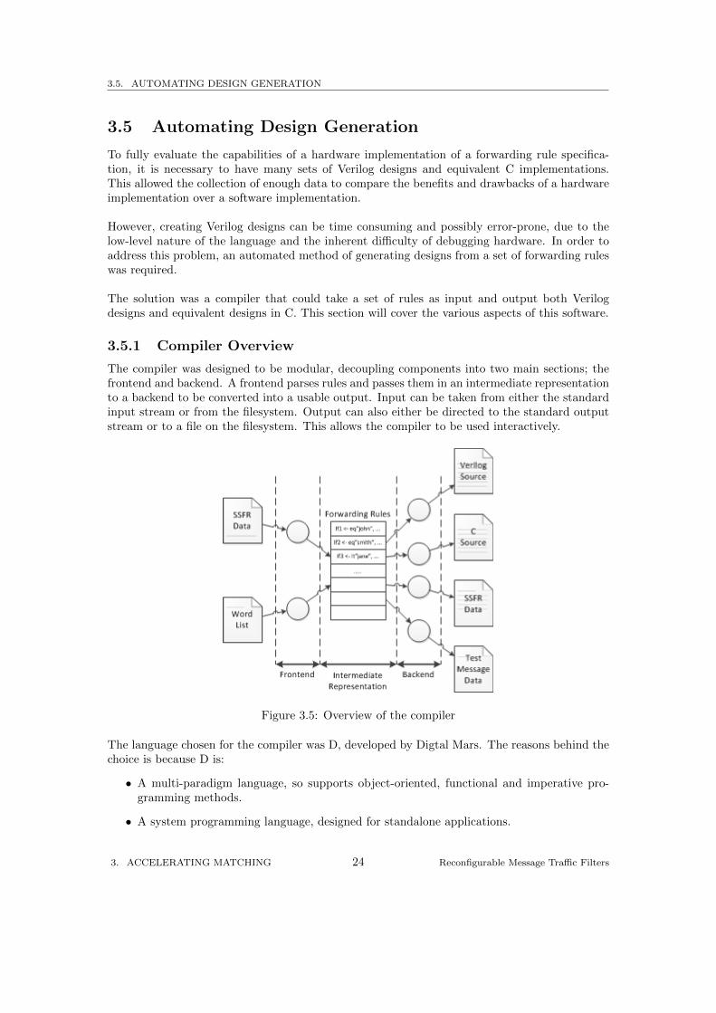
The compiler was designed to be modular, decoupling components into two main sections; thefrontend and backend. A frontend parses rules and passes them in an intermediate representationto a backend to be converted into a usable output. Input can be taken from either the standardinput stream or from the filesystem. Output can also either be directed to the standard outputstream or to a file on the filesystem. This allows the compiler to be used interactively.
Figure 3.5: Overview of the compiler
The language chosen for the compiler was D, developed by Digtal Mars. The reasons behind thechoice is because D is:
• A multi-paradigm language, so supports object-oriented, functional and imperative pro-gramming methods.
• A system programming language, designed for standalone applications.
3. ACCELERATING MATCHING 24 Reconfigurable Message Traffic Filters
3.5. AUTOMATING DESIGN GENERATION
• Compiled, offering good performance, but still platform-agnostic.
• High-level, providing advanced features such as automatic garbage collection, delegates andclosure, allowing for concise intent-driven code.
The following subsections will discuss the key aspects of the compiler shown in Figure 3.5 infurther detail.
Intermediate Representation
To pass forwarding rule specifications from frontend to backend, a suitable data structure wasneeded, both to ease the processing burden on backend modules and to reduce the memoryfootprint. To do this, forwarding rules are split into several sets:
• A map of all string patterns in the rules to all the operators that affect the patterns.
• A set of terms used throughout the forwarding rule specification.
• A set of filters used throughout the forwarding rule specification as collections of terms.
• A map of interface names to collections of filters that comprise the interface rules.
Each element in a set is identified by their properties. For example, a filter would be deemedas equal to another if their collections of terms were equal. This was a simple way of reducingthe amount of potential code duplication that could occur in the backend modules should twoidentical filters be treated as separate.
Frontend
Two frontend modules were implemented. The first module can parse simple string forwardingrules (SSFR) described in 3.5.2 into a forwarding rule specification. The second module canparse a word list and generate a forwarding rule specification based on user input parameters.Parameters cover the number of interfaces, the number of filters per interface, the number ofterms per filter and the word lengths used, as well as distinct filter, term and word counts.
Backend
Four backends were implemented to convert the forwarding rule specifications passed to theminto the following outputs:
• C source code.
• Verilog source code.
• SSFR data.
• Test message data in comma-separated value (CSV) format.
The test message data frontend can generate test message data to target filters in the forwardingrule specification passed to it, or it can generate a set of random messages to check for false-positives.
Both the Verilog and C source code frontends can take a test message file generated previ-ously and include test bed data in their output to validate the designs against a set of generated
3. ACCELERATING MATCHING 25 Reconfigurable Message Traffic Filters
3.5. AUTOMATING DESIGN GENERATION
test cases.
The SSFR backend was included to provide an output for the rule-generator frontend, howeverrules can be generated straight to source code if desired.
3.5.2 Rule Format
The simple string forwarding rule (SSFR) language was designed to be as close to the predicatelanguage described in 3.2, but also to be simple to parse. The Backus-Naur Form (BNF) syntaxof the rules are given in Listing 5.
Listing 5 BNF syntax of SSFR
〈rule〉 ::= 〈ident〉 ‘:’ 〈filter〉 {’|’ 〈filter〉} ‘;’
〈filter〉 ::= 〈term〉 {‘,’ 〈term〉}〈term〉 ::= 〈op〉 〈string〉〈ident〉 ::= (‘a’...‘z’ | ‘A’...‘Z’ | ‘0’...‘9’ | ‘ ’)+
〈string〉 ::= ‘"’ (/* all letters except ‘"’ */)+ ‘"’
The forwarding rules presented as a set of predicate rules in Listing 4 in 3.2.2 can be representedin SSFR as shown in Listing 6. There is no need to include any brackets in SSFR since rules canonly be disjunctions of filters and filters can only be conjunctions of terms.
Listing 6 SSFR representation of Listing 4
i1 : eq"john", eq"smith" | eq"sir";
i2 : eq"smith", eq"mrs." | eq"jane";
i3 : eq"mr." | eq"sir";
i4 : ss"james" | pf"mary", sf"bob";
i5 : lt"james" | gt"mary";
3.5.3 Validation of Compiler Output
One of the most important processes in any implementation of a compiler is to ensure that theoutput of the compiler is correct with regards to the input. This was achieved initially with theintroduction of static test harnesses that imported the output code of small hand-written rulesets. Each filter in a rule was tested on a case-by-case basis, with hand-written sample messages.
While this approach was acceptable for small examples, it was impractical as rule set sizes in-creased. In particular, it could not evaluate whether larger rule sizes could cause problems in thegenerated code due to possible interactions between the portions of generated code for each term.
The design of the automated compiler presented a solution to the problem. By leveraging theautomatic code generation facilities provided by the compiler, test cases can be developed by aspecialised backend. The intermediate representation of rules sets are parsed into message datatargeted towards specific filters.
3. ACCELERATING MATCHING 26 Reconfigurable Message Traffic Filters
3.5. AUTOMATING DESIGN GENERATION
The message data is then included in the code generation processes of the C and Verilog sourcecode frontends. The frontends evaluate each test message and produce a set of test cases withexpected results. These test cases are then packaged into either a main function for the C imple-mentation, or a separate test bench module for the Verilog implementation, and included withthe forwarding logic.
This automatic test case generation, coupled with the forwarding rule generator frontend de-tailed in 3.5.1, allowed multiple tests to be run with many diverse sets of test cases to ensure thevalidity of both the C and Verilog forwarding logic.
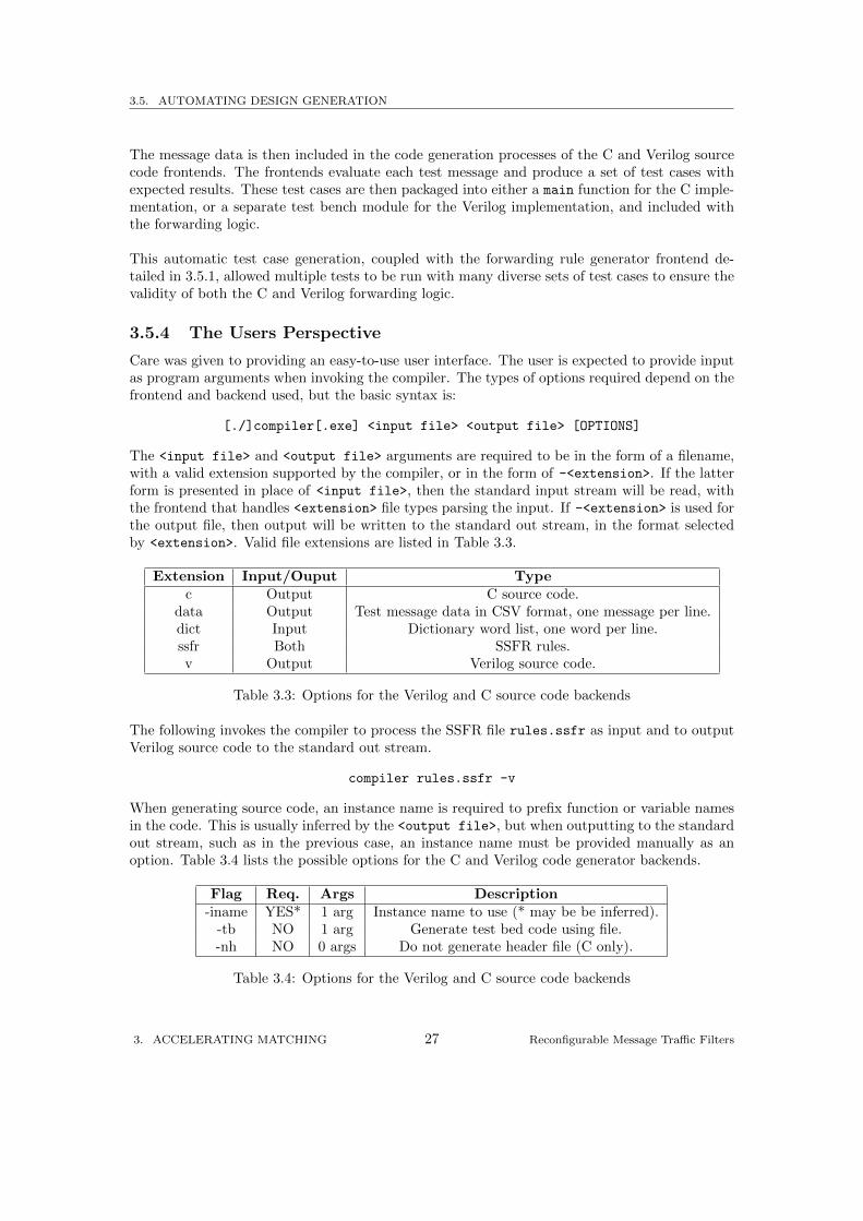
3.5.4 The Users Perspective
Care was given to providing an easy-to-use user interface. The user is expected to provide inputas program arguments when invoking the compiler. The types of options required depend on thefrontend and backend used, but the basic syntax is:
[./]compiler[.exe] <input file> <output file> [OPTIONS]
The <input file> and <output file> arguments are required to be in the form of a filename,with a valid extension supported by the compiler, or in the form of -<extension>. If the latterform is presented in place of <input file>, then the standard input stream will be read, withthe frontend that handles <extension> file types parsing the input. If -<extension> is used forthe output file, then output will be written to the standard out stream, in the format selectedby <extension>. Valid file extensions are listed in Table 3.3.
Extension Input/Ouput Typec Output C source code.
data Output Test message data in CSV format, one message per line.dict Input Dictionary word list, one word per line.ssfr Both SSFR rules.v Output Verilog source code.
Table 3.3: Options for the Verilog and C source code backends
The following invokes the compiler to process the SSFR file rules.ssfr as input and to outputVerilog source code to the standard out stream.
compiler rules.ssfr -v
When generating source code, an instance name is required to prefix function or variable namesin the code. This is usually inferred by the <output file>, but when outputting to the standardout stream, such as in the previous case, an instance name must be provided manually as anoption. Table 3.4 lists the possible options for the C and Verilog code generator backends.
Flag Req. Args Description-iname YES* 1 arg Instance name to use (* may be be inferred).
-tb NO 1 arg Generate test bed code using file.-nh NO 0 args Do not generate header file (C only).
Table 3.4: Options for the Verilog and C source code backends
3. ACCELERATING MATCHING 27 Reconfigurable Message Traffic Filters
3.5. AUTOMATING DESIGN GENERATION
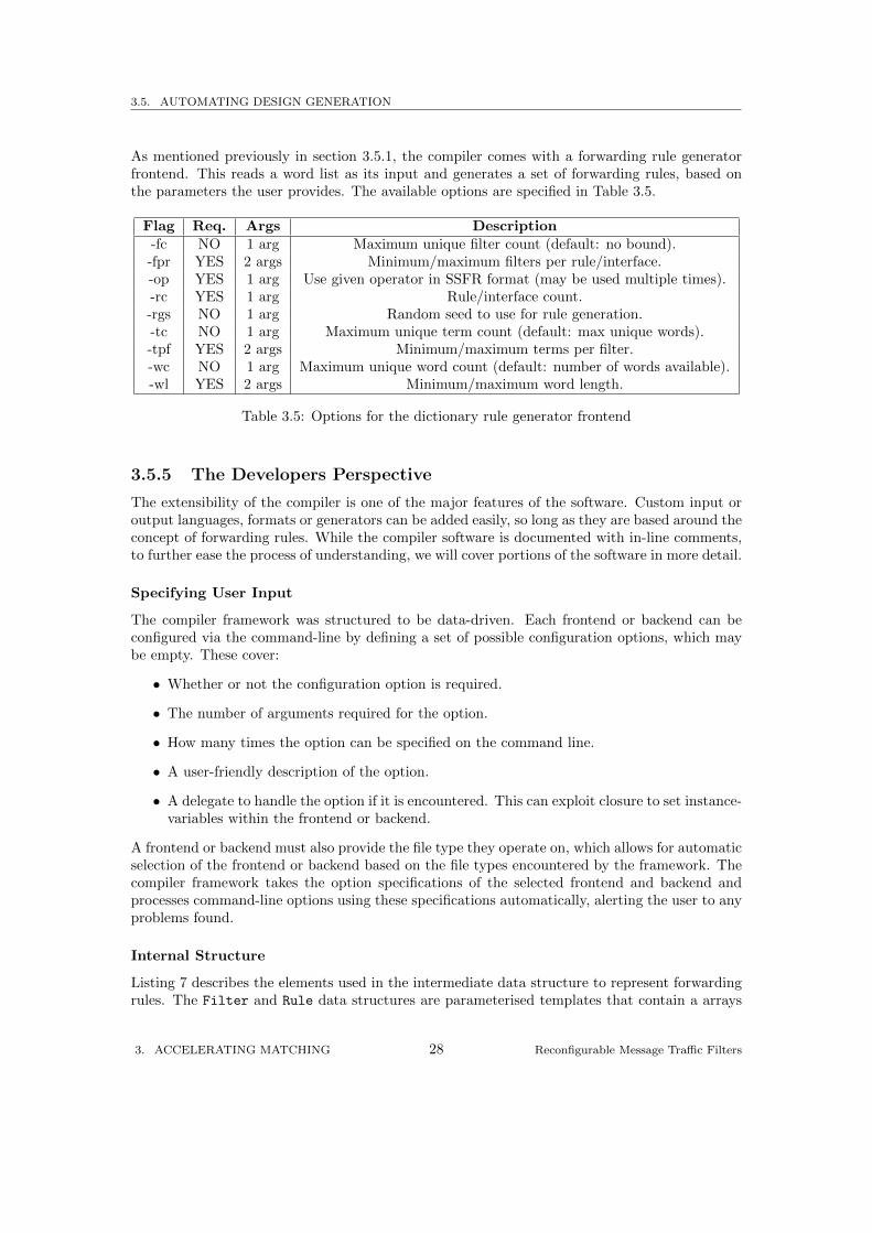
As mentioned previously in section 3.5.1, the compiler comes with a forwarding rule generatorfrontend. This reads a word list as its input and generates a set of forwarding rules, based onthe parameters the user provides. The available options are specified in Table 3.5.
Flag Req. Args Description-fc NO 1 arg Maximum unique filter count (default: no bound).-fpr YES 2 args Minimum/maximum filters per rule/interface.-op YES 1 arg Use given operator in SSFR format (may be used multiple times).-rc YES 1 arg Rule/interface count.-rgs NO 1 arg Random seed to use for rule generation.-tc NO 1 arg Maximum unique term count (default: max unique words).-tpf YES 2 args Minimum/maximum terms per filter.-wc NO 1 arg Maximum unique word count (default: number of words available).-wl YES 2 args Minimum/maximum word length.
Table 3.5: Options for the dictionary rule generator frontend
3.5.5 The Developers Perspective
The extensibility of the compiler is one of the major features of the software. Custom input oroutput languages, formats or generators can be added easily, so long as they are based around theconcept of forwarding rules. While the compiler software is documented with in-line comments,to further ease the process of understanding, we will cover portions of the software in more detail.
Specifying User Input
The compiler framework was structured to be data-driven. Each frontend or backend can beconfigured via the command-line by defining a set of possible configuration options, which maybe empty. These cover:
• Whether or not the configuration option is required.
• The number of arguments required for the option.
• How many times the option can be specified on the command line.
• A user-friendly description of the option.
• A delegate to handle the option if it is encountered. This can exploit closure to set instance-variables within the frontend or backend.
A frontend or backend must also provide the file type they operate on, which allows for automaticselection of the frontend or backend based on the file types encountered by the framework. Thecompiler framework takes the option specifications of the selected frontend and backend andprocesses command-line options using these specifications automatically, alerting the user to anyproblems found.
Internal Structure
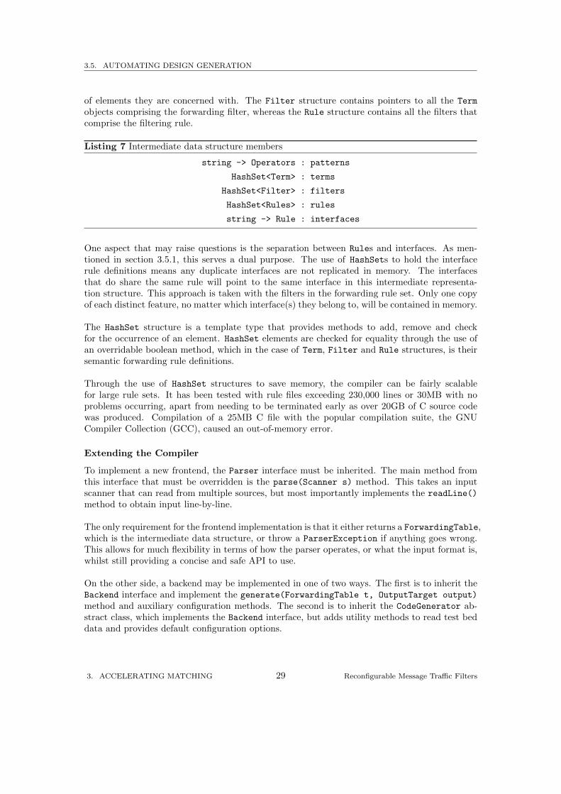
Listing 7 describes the elements used in the intermediate data structure to represent forwardingrules. The Filter and Rule data structures are parameterised templates that contain a arrays
3. ACCELERATING MATCHING 28 Reconfigurable Message Traffic Filters
3.5. AUTOMATING DESIGN GENERATION
of elements they are concerned with. The Filter structure contains pointers to all the Term
objects comprising the forwarding filter, whereas the Rule structure contains all the filters thatcomprise the filtering rule.
Listing 7 Intermediate data structure members
string -> Operators : patterns
HashSet<Term> : terms
HashSet<Filter> : filters
HashSet<Rules> : rules
string -> Rule : interfaces
One aspect that may raise questions is the separation between Rules and interfaces. As men-tioned in section 3.5.1, this serves a dual purpose. The use of HashSets to hold the interfacerule definitions means any duplicate interfaces are not replicated in memory. The interfacesthat do share the same rule will point to the same interface in this intermediate representa-tion structure. This approach is taken with the filters in the forwarding rule set. Only one copyof each distinct feature, no matter which interface(s) they belong to, will be contained in memory.
The HashSet structure is a template type that provides methods to add, remove and checkfor the occurrence of an element. HashSet elements are checked for equality through the use ofan overridable boolean method, which in the case of Term, Filter and Rule structures, is theirsemantic forwarding rule definitions.
Through the use of HashSet structures to save memory, the compiler can be fairly scalablefor large rule sets. It has been tested with rule files exceeding 230,000 lines or 30MB with noproblems occurring, apart from needing to be terminated early as over 20GB of C source codewas produced. Compilation of a 25MB C file with the popular compilation suite, the GNUCompiler Collection (GCC), caused an out-of-memory error.
Extending the Compiler
To implement a new frontend, the Parser interface must be inherited. The main method fromthis interface that must be overridden is the parse(Scanner s) method. This takes an inputscanner that can read from multiple sources, but most importantly implements the readLine()
method to obtain input line-by-line.
The only requirement for the frontend implementation is that it either returns a ForwardingTable,which is the intermediate data structure, or throw a ParserException if anything goes wrong.This allows for much flexibility in terms of how the parser operates, or what the input format is,whilst still providing a concise and safe API to use.
On the other side, a backend may be implemented in one of two ways. The first is to inherit theBackend interface and implement the generate(ForwardingTable t, OutputTarget output)
method and auxiliary configuration methods. The second is to inherit the CodeGenerator ab-stract class, which implements the Backend interface, but adds utility methods to read test beddata and provides default configuration options.
3. ACCELERATING MATCHING 29 Reconfigurable Message Traffic Filters
3.5. AUTOMATING DESIGN GENERATION
The second method simplifies the work required to implement a code-generating backend, butfor data-generation purposes, for example, the plain Backend interface should suffice. Again, likeimplementing a frontend, the API has been designed to be concise, but easy to use. Output iscontrolled by calling open() on the OutputTarget passed to the generate method, which returnsa Writer that performs automatic indentation and allows output to be written to various sources.
As an addition to being able to input and output to files and the standard input or outputstream, additional Scanner and OutputTarget types allow input or output to text buffers. If theframework was modified, or if a new framework was written, different stages could be pipelinedthrough the use of text buffers. This is a prime example of the utility of the overall codebase.
3. ACCELERATING MATCHING 30 Reconfigurable Message Traffic Filters
4
Evaluation
To benchmark the performance of the hardware designs we covered in the previous chapter, we setup a series of test cases. We leveraged the rule and test data generation facilities of the compilerto generate equivalent C and Verilog implementations for increasing numbers of interfaces overdifferent sets of filters per interface and terms per filter. The test setup is described in section 4.1.
The C source code was compiled into executable format and run to obtain readings, but theVerilog code was timed by specialised FPGA software provided by Xilinx. Per-message and per-character timings were obtained. The factor of speedup was calculated, and auxiliary data suchas executable size and power requirements was collected. The analysis and graphs of this dataare presented in section 4.2.
4. EVALUATION 31 Reconfigurable Message Traffic Filters
4.1. TEST SETUP
4.1 Test Setup
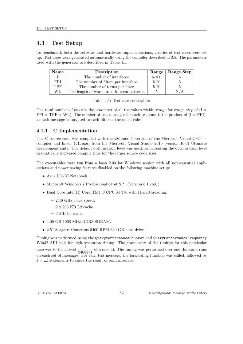
To benchmark both the software and hardware implementations, a series of test cases were setup. Test cases were generated automatically using the compiler described in 3.5. The parametersused with the generator are described in Table 4.1.
Name Description Range Range StepI The number of interfaces. 5-100 5
FPI The number of filters per interface. 5-20 5TPF The number of terms per filter. 5-20 5WL The length of words used in term patterns. 5 N/A
Table 4.1: Test case constraints
The total number of cases is the power set of all the values within range for range step of (I ×FPI × TPF ×WL). The number of test messages for each test case is the product of (I × FPI),as each message is targeted to each filter in the set of rules.
4.1.1 C Implementation
The C source code was compiled with the x86 amd64 version of the Microsoft Visual C/C++compiler and linker (cl.exe) from the Microsoft Visual Studio 2010 (version 10.0) Ultimatedevelopment suite. The default optimisation level was used, as increasing the optimisation leveldramatically increased compile time for the larger source code sizes.
The executables were run from a bash 2.03 for Windows session with all non-essential appli-cations and power saving features disabled on the following machine setup:
• Asus U35JC Notebook.
• Microsoft Windows 7 Professional 64bit SP1 (Version 6.1.7601).
• Dual Core Intel(R) Core(TM) i3 CPU M 370 with Hyperthreading.
– 2.40 GHz clock speed.
– 2 x 256 KB L2 cache.
– 3 MB L3 cache.
• 4.00 GB 1066 MHz DDR3 SDRAM.
• 2.5” Seagate Momentus 5400 RPM 320 GB hard drive.
Timing was performed using the QueryPerformanceCounter and QueryPerformanceFrequency
Win32 API calls for high-resolution timing. The granularity of the timings for this particular
case was to the closest1
2408271of a second. The timing was performed over one thousand runs
on each set of messages. For each test message, the forwarding function was called, followed byI × if statements to check the result of each interface.
4. EVALUATION 32 Reconfigurable Message Traffic Filters
4.1. TEST SETUP
4.1.2 Verilog Implementation
The Xilinx Virtex6 xc6vlx75t-ff484-3 FPGA was used as a target for all compilation and routingof the source code. The Verilog source code was compiled, mapped, placed and routed using theXilinx 64bit ISE Design Tools 13.1 suite on Microsoft Windows 7 Professional 64bit. The stepsfollowed to obtain a fully placed and routed design for timing were:
• xst with the -opt mode Speed -opt level 1 flags passed to the run command.
• ngdbuild with timing constraints of 12ns HIGH 50%.
• map with options -ol std -t 1 -xt 0 -register duplication off -r 4 -global opt
off -mt 4 -detail -ir off -pr off -lc off -power off.
• par with options -mt 4 -ol std.
Minimum clock period timings and resource utilisation counts were then obtained from the finalreport given by the par command.
In addition to placing and routing, power estimates were obtained by using the Xilinx XPowercommand-line tool, xpwr, with the flag -ol std.
4. EVALUATION 33 Reconfigurable Message Traffic Filters
4.2. RESULTS
4.2 Results
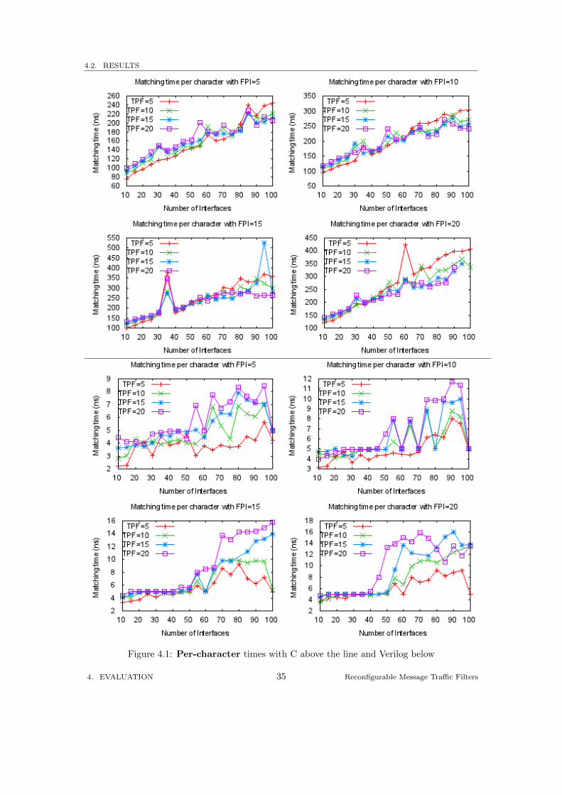
4.2.1 Per-character Timings
The C experimental readings were based on one thousand runs of multiple messages each. Toobtain the per-character timings, the readings were first divided by one thousand, and then di-vided by the number of total characters in the set of messages. The result was then adjustedfrom millisecond units to nanosecond units to be on par with the Verilog readings.
The top four graphs in Figure 4.1 give the per-character times of the C implementation. Con-trasting the C timings with the Verilog timings in the bottom four graphis in Figure 4.1, oneobvious feature to note is the different scales used. While the C timings range from 75.2ns to421ns, the Verilog timings range from 2.21ns to 12.3ns.
The huge difference in the times can be mainly attributed down to the properties of the DCAMarchitecture used in the Verilog implementation. The C implementation reduced the number ofpossible character comparisons through the use of trie structures, but due to its single-threadednature, only one character comparison can be performed at a time. In addition to the multiplecharacter comparisons, the C implementation compares each tag in a message multiple timesstarting at each character of a tag to match the sf and ss operators. In contrast, the DCAMarchitecture uses multiple character comparators in parallel. This results in multiple charac-ter comparisons per clock cycle. As a consequence, each character in an input message is onlyrequired to be processed once, as shift registers deal with offsets of characters in a tag.
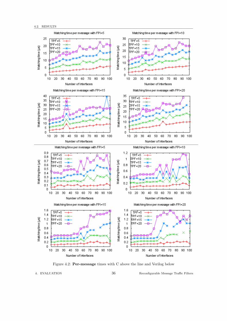
4.2.2 Per-message Timings
For the C implementation, there are fixed costs involved with calling functions and initialisingvariables. While the unit of processing for the Verilog forwarding function is an input character,the unit of processing for the C forwarding function is a whole message. This means for everymessage, these fixed costs are applied to the C implementations execution time, so there is aneed to provide timings per message.
To adjust the Verilog per-character cycle timings to per-message timings, each cycle time wasmultiplied by the number of characters in a potential test message with the FPI and TPF con-straints specified. The top four graphs in Figure 4.2 give the per-message times for the C imple-mentation, which can be compared with the bottom four graphs of the Verilog per-message times.
The Verilog per-message timings start off quite constant, before increasing after around 50 in-terfaces. This could be due to the placer choosing less-than optimal designs to reduce placementtime in large search spaces. This would explain why the results for the lower FPI and TPFcounts are flatter and have less variation. Further testing over larger data sets would be requiredto confirm this. The placer would also need to be set to high effort level when selecting routings.
The C per-message timings appear to be more or less linear, with equal spacing between theTPF tiers. There are several spikes, most notably where FPI is 15 and interface count is 35.These spikes could be caused by the selection of terms used. Again, the linearity would need tobe confirmed by using larger rule sets.
4. EVALUATION 34 Reconfigurable Message Traffic Filters
4.2. RESULTS
Figure 4.1: Per-character times with C above the line and Verilog below
4. EVALUATION 35 Reconfigurable Message Traffic Filters
4.2. RESULTS
Figure 4.2: Per-message times with C above the line and Verilog below
4. EVALUATION 36 Reconfigurable Message Traffic Filters
4.2. RESULTS
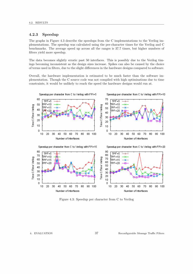
4.2.3 Speedup
The graphs in Figure 4.3 describe the speedups from the C implementations to the Verilog im-plementations. The speedup was calculated using the per-character times for the Verilog and Cbenchmarks. The average speed up across all the ranges is 37.7 times, but higher numbers offilters yield more speedup.
The data becomes slightly erratic past 50 interfaces. This is possibly due to the Verilog tim-ings becoming inconsistent as the design sizes increase. Spikes can also be caused by the choiceof terms used in filters, due to the slight differences in the hardware designs compared to software.
Overall, the hardware implementation is estimated to be much faster than the software im-plementation. Though the C source code was not compiled with high optimisations due to timeconstraints, it would be unlikely to reach the speed the hardware designs would run at.
Figure 4.3: Speedup per character from C to Verilog
4. EVALUATION 37 Reconfigurable Message Traffic Filters
4.3. RESOURCE UTILISATION
4.3 Resource Utilisation
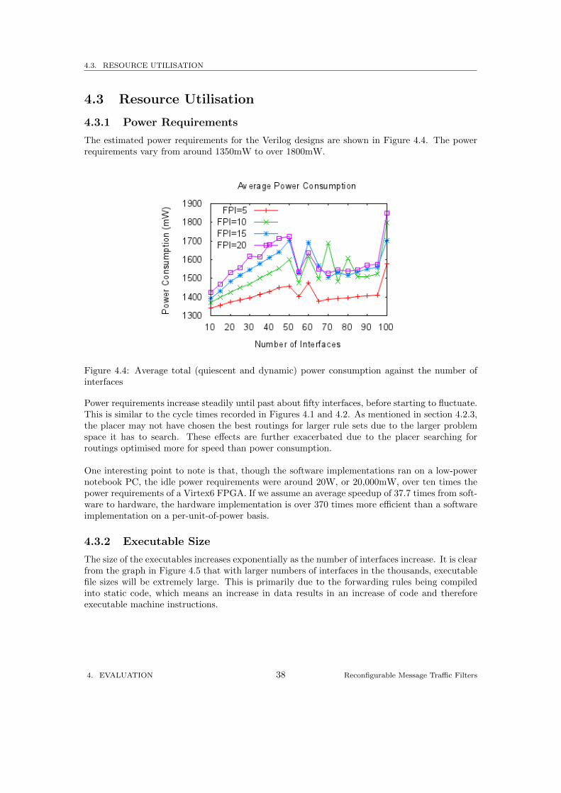
4.3.1 Power Requirements
The estimated power requirements for the Verilog designs are shown in Figure 4.4. The powerrequirements vary from around 1350mW to over 1800mW.
Figure 4.4: Average total (quiescent and dynamic) power consumption against the number ofinterfaces
Power requirements increase steadily until past about fifty interfaces, before starting to fluctuate.This is similar to the cycle times recorded in Figures 4.1 and 4.2. As mentioned in section 4.2.3,the placer may not have chosen the best routings for larger rule sets due to the larger problemspace it has to search. These effects are further exacerbated due to the placer searching forroutings optimised more for speed than power consumption.
One interesting point to note is that, though the software implementations ran on a low-powernotebook PC, the idle power requirements were around 20W, or 20,000mW, over ten times thepower requirements of a Virtex6 FPGA. If we assume an average speedup of 37.7 times from soft-ware to hardware, the hardware implementation is over 370 times more efficient than a softwareimplementation on a per-unit-of-power basis.
4.3.2 Executable Size
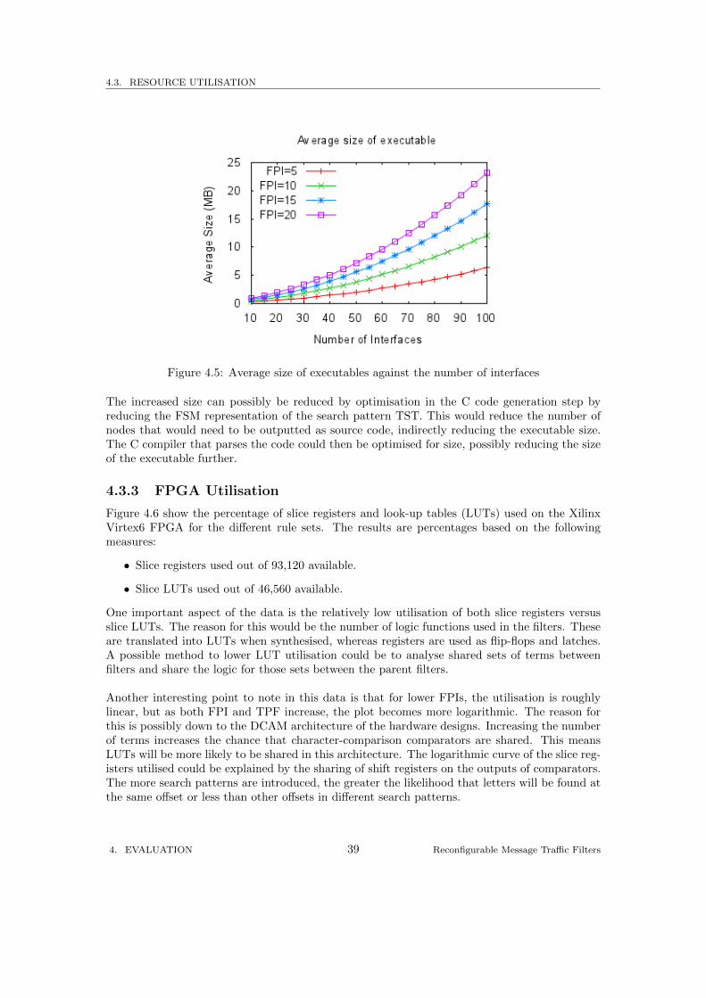
The size of the executables increases exponentially as the number of interfaces increase. It is clearfrom the graph in Figure 4.5 that with larger numbers of interfaces in the thousands, executablefile sizes will be extremely large. This is primarily due to the forwarding rules being compiledinto static code, which means an increase in data results in an increase of code and thereforeexecutable machine instructions.
4. EVALUATION 38 Reconfigurable Message Traffic Filters
4.3. RESOURCE UTILISATION
Figure 4.5: Average size of executables against the number of interfaces
The increased size can possibly be reduced by optimisation in the C code generation step byreducing the FSM representation of the search pattern TST. This would reduce the number ofnodes that would need to be outputted as source code, indirectly reducing the executable size.The C compiler that parses the code could then be optimised for size, possibly reducing the sizeof the executable further.
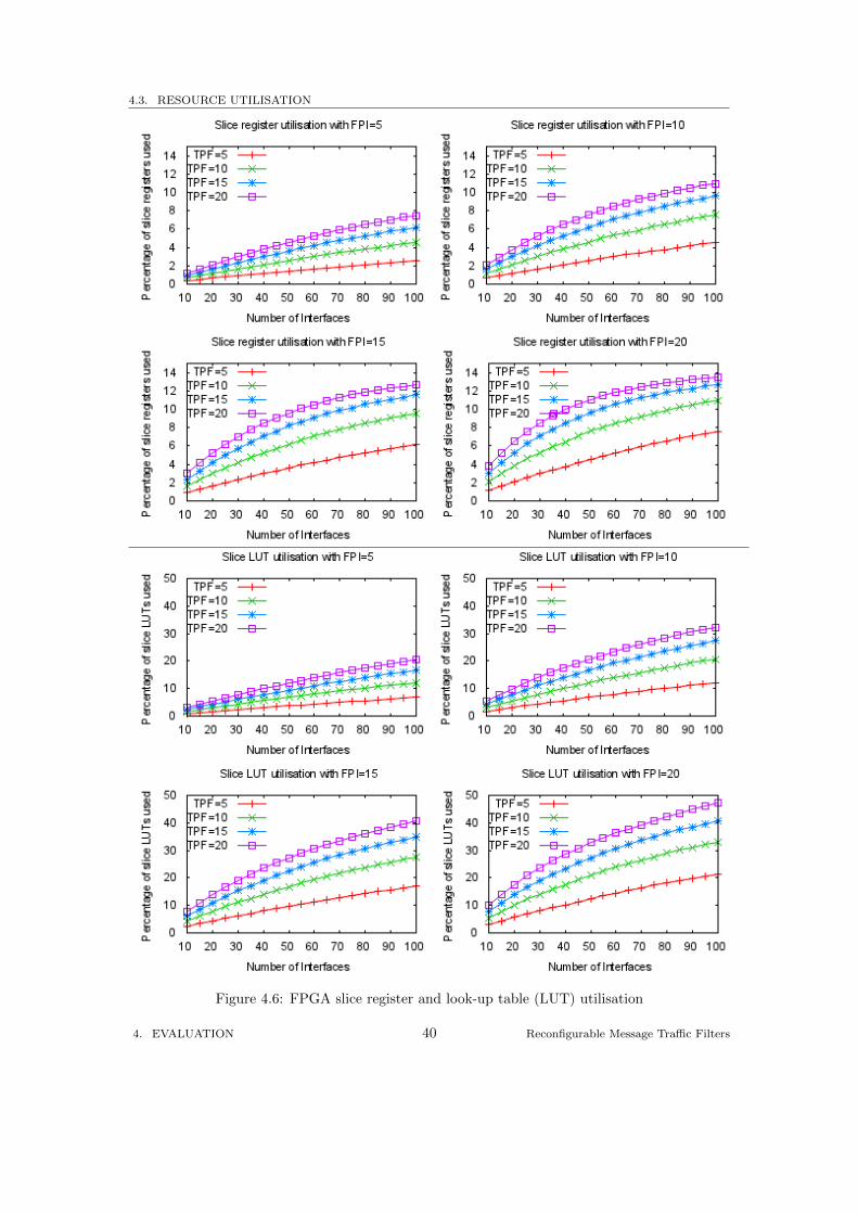
4.3.3 FPGA Utilisation
Figure 4.6 show the percentage of slice registers and look-up tables (LUTs) used on the XilinxVirtex6 FPGA for the different rule sets. The results are percentages based on the followingmeasures:
• Slice registers used out of 93,120 available.
• Slice LUTs used out of 46,560 available.
One important aspect of the data is the relatively low utilisation of both slice registers versusslice LUTs. The reason for this would be the number of logic functions used in the filters. Theseare translated into LUTs when synthesised, whereas registers are used as flip-flops and latches.A possible method to lower LUT utilisation could be to analyse shared sets of terms betweenfilters and share the logic for those sets between the parent filters.
Another interesting point to note in this data is that for lower FPIs, the utilisation is roughlylinear, but as both FPI and TPF increase, the plot becomes more logarithmic. The reason forthis is possibly down to the DCAM architecture of the hardware designs. Increasing the numberof terms increases the chance that character-comparison comparators are shared. This meansLUTs will be more likely to be shared in this architecture. The logarithmic curve of the slice reg-isters utilised could be explained by the sharing of shift registers on the outputs of comparators.The more search patterns are introduced, the greater the likelihood that letters will be found atthe same offset or less than other offsets in different search patterns.
4. EVALUATION 39 Reconfigurable Message Traffic Filters
4.3. RESOURCE UTILISATION
Figure 4.6: FPGA slice register and look-up table (LUT) utilisation
4. EVALUATION 40 Reconfigurable Message Traffic Filters
4.4. SUMMARY
4.4 Summary
The evaluations of both the Verilog and C implementations show that the Verilog implemen-tations are much faster than the C implementations by a factor over 37 times. The estimatedpower requirements also showed that the Verilog implementations consume much less power thana traditional notebook PC. The findings highlight the potentially massive gains in both perfor-mance and power-efficiency directed FPGA solutions have over conventional software solutions.
One point to note, however, is that the Verilog results are estimates by the Xilinx FPGA tools,rather than experimental run-times recorded. We are confident that the timings will be accurate,as unlike a traditional software set up, there are no additional processes to consider, which wouldnormally be found on a multi-tasking operating system.
It would nevertheless be preferable to validate the Verilog results on a physical FPGA in fu-ture work, particularly in terms of power requirements, as environment can play a huge role inoverall results. Due to time constraints, larger rule sets could not be covered, but this could bean area of future research to further expand the breadth of the data.
4. EVALUATION 41 Reconfigurable Message Traffic Filters
5
Conclusions and Future Work
From the results it is clear that a hardware implementation on an FPGA is much faster thanan equivalent software implementation. The estimated average speed of a hardware solutionrunning in a Xilinx Virtex6 FPGA is around 37 times faster than an equivalent solution runningon a 2.40GHz dual-core Intel Core i3. The power efficiency statistics are even more exciting, aswith the higher performance and lower power consumption, the Xilinx Virtex6 is estimated to bearound 370 times more power efficient. However, one important part that was not covered wasthe time taken to produce a working implementation from a set of rules. While the time takento compile a set of rules into either C or Verilog code was minimal, the time taken to compilethe C or to place and route the Verilog code increased substantially for larger problem sizes.
The main cause of the long compilation and routing times is down to how the source codeproduced is a static schematic of the forwarding logic. The larger the set of rules, the larger theoverall source code will be. For the C code, the addition of more filters requires the additionof more stack variables to hold the state of matching on those filters. The addition of morematching terms requires additional states in the search pattern TST FSM. This requires moretime for a C compiler to parse, analyse and optimise the code and produce valid machine code.The addition of more stack variables increases the likelihood that the stack size allocated tothe executable wont be large enough. Stack overflows occurred for the larger designs involvinggreater than thirty thousand terms, or over two thousand filters, due to the large numbers offilter stack variables used.
On the Verilog side, increases in rule sizes translate to increases in logic elements used. Thisresults in highly dense and difficult-to-route designs, which require extra time for placer softwareto process. Large numbers of logic elements may also result in much higher timings, due to thedelays introduced by routing signals between logic elements. Routing some of the larger designsoccasionally took many hours for this reason.
Because of this drawback, both the concept of static hardware designs and the compiler softwareare suited more towards smaller rule sets, or rule sets that are rarely updated. This presents twoviable avenues for future work. The first would be to investigate a more generalised solution.The second would be to explore the potential speedups that can be obtained from using a staticdesign process as an extension to an existing solution such as Siena Fast Forwarding. Thesealternatives will be discussed in the following sections of this chapter.
5. CONCLUSIONS AND FUTURE WORK 42 Reconfigurable Message Traffic Filters
Continuing on with the same design, there are optimisations that can possibly further increasethe overall speed of the hardware designs. One such optimisation is pipelining, where delayregisters are inserted between logic elements to break up long paths. This can potentially in-crease clock speed by reducing the amount of routing delay in the design, thereby increasing thepotential overall speed of the design.
The C designs outputted by the compiler may be optimised further by exploring techniquesto reduce the FSM produced by the TST. Filter variables could also be moved off the stack intoa structure that is passed to the forwarding function as a parameter by the user. This wouldallow the user to choose whether the temporary filter variables are allocated on the stack orin the heap. Situations where this may be beneficial would be where there are many filters,requiring a large chunk of stack space that may not be provided by the runtime environment.This enhances the scalability of the system and provides the user finer-grained control over theoperation of the forwarding logic.
5. CONCLUSIONS AND FUTURE WORK 43 Reconfigurable Message Traffic Filters
5.1. APPLICATIONS AND FUTURE WORK
5.1 Applications and Future Work
In this section we will two main possible applications and future developments of this project.While it would have been desirable to have investigated these paths in this project, there wasinsufficient time. Instead, this project hopes to have laid the groundwork by highlighting thebenefits of FPGA designs over software designs, and producing tools to assist with future devel-opment of the ideas laid out here.
5.1.1 Generalised Design
This project focussed on producing static designs from rule sets. The cost of this method isscalability and flexibility; however the results showed that FPGAs can achieve massive speedupsover software. A potential course that could be taken would be to diverge from static designs onto dynamic designs.
A general design that would take configuration data to determine its operation can be writ-ten by hand in Verilog. This could then be mapped, placed and routed to an FPGA chip withmaximum optimisations selected, as the design would not need to be changed once the routingis complete. The compiler written for this project could then be adapted with a new backend toproduce configuration data for this hardware skeleton from a set of rules.
Whenever a rule set needs to be changed, the time taken from receipt of the new rules to ahardware implementation of those rules would be greatly minimised from a static deployment.Rules would just need to be translated to configuration data, which would then be sent to thehardware, replacing the old configuration data.
A further expansion onto this would utilise the processes of self-reconfiguration explained in2.4. This would make the most of the reconfigurability of FPGA hardware as the hardwarewould truly be self-reconfiguring instead of merely reading a new set of configuration data asinstructions like a desktop CPU.
This approach could be combined with the technique detailed in the next section, just-in-timecompilation.
5.1.2 As a Just-in-Time (JIT) Extension
Substantial performance increases can be obtained by synthesising forwarding logic into hard-ware. It was pointed out earlier that larger rule sets can be a problem with regards to the timetaken to synthesise a design. On its own, the designs do not take into account any concept ofkey/value tags, so attributes that are a common feature of messages cannot be dealt with in aconventional way. This means as a standalone system, a static design, such as one produced bythe rule compiler, may not be the best idea.
One avenue that could be explored would be to integrate both the compiler and the staticdesign process with a larger system such as Siena Fast Forwarding. Potential speed ups can beobtained, as the static nature of both the software and hardware output of the compiler reducesthe memory lookups attributed with data-driven implementations such as SFF. However, sincethe designs outputted by the compiler do not account for attribute keys, this process can beoffloaded onto the SFF implementation.
5. CONCLUSIONS AND FUTURE WORK 44 Reconfigurable Message Traffic Filters
5.1. APPLICATIONS AND FUTURE WORK
One of the key features of SFF is the minimisation of the filtering workload through pre-processingmessage attributes and discarding the filtering constraints that do not apply to the current mes-sage. If one were to harness this feature and record which attributes are commonly selected forfiltering, the most commonly selected attributes may be identified.
With this list of commonly selected attributes, the search patterns and operators for these valuescould be passed to the compiler which could produce either an optimised static C representation,or a Verilog representation. This output could then either be compiled into software or synthe-sised into hardware and used in place of the SFF filtering.
This is similar to Just-In-Time (JIT) compilation used by the Java Virtual Machine (JVM),where directly interpretable representation (DIR) code is translated into directly executable rep-resentation (DER) code. The Java HotSpot Server VM uses a mixed-mode JIT strategy thatinvolved compiling only the most-used portions of byte-code into native code, while still inter-preting byte-code until it has completed [1].
With the SFF/static design software, a mixed-mode strategy could be pursued, where rules arestill processed by the default SFF forwarding logic until a hardware implementation is loadedonto an FPGA, or a static software forwarding function is linked into the main executable. Dueto the modular nature of the compiler, it can be easily extended to a runtime compiler. Instead ofproducing C output for software designs, new backends could be implemented to output machinecode specific to the machine architecture the SFF router is running on. This could bypass thesteps normally required and reduce the dependency on external compilers.
Since the constraints selected for JIT would be the forwarding rule “hotspots”, it is highlylikely that they would be the weakest link in terms of forwarding speed for the SFF algorithmor any other this technique is applied to. By targeting these key areas, the overall throughputfor such an algorithm could be increased, enhancing the scalability of an implementation.
In this capacity, there could be infinitely many possible applications for this work. Good exam-ples would be where there is a high volume of message traffic, such as in the financial industryfor routing market data, or e-commerce datacentres.
5. CONCLUSIONS AND FUTURE WORK 45 Reconfigurable Message Traffic Filters
BIBLIOGRAPHY
Bibliography
[1] Arnold, M., Fink, S. J., Grove, D., Hind, M., and Sweeney, P. F. A surveyof adaptive optimization in virtual machines. In PROCEEDINGS OF THE IEEE, 93(2),2005. SPECIAL ISSUE ON PROGRAM GENERATION, OPTIMIZATION, AND ADAP-TATION (2004).
[2] Bentley, J. L., and Sedgewick, R. Fast algorithms for sorting and searching strings,1997.
[3] Brown, S., and Rose, J. FPGA and CPLD architectures: a tutorial. Design Test ofComputers, IEEE 13, 2 (1996), 42 –57.
[4] Bu, L., and Chandy, J. A. FPGA based network intrusion detection using contentaddressable memories. In Proceedings of the 12th Annual IEEE Symposium on Field-Programmable Custom Computing Machines (Washington, DC, USA, 2004), IEEE Com-puter Society, pp. 316–317.
[5] Cai, Z., Wang, Z., and Zheng, K. A distributed TCAM coprocessor architecture forintegrated policy filtering and content filtering. In Communications (ICC), 2010 IEEEInternational Conference on (May 2010), pp. 1 –5.
[6] Carzaniga, A., and Wolf, A. L. Content-based networking: A new communicationinfrastructure. In Revised Papers from the NSF Workshop on Developing an Infrastructurefor Mobile and Wireless Systems (London, UK, 2002), IMWS ’01, Springer-Verlag, pp. 59–68.
[7] Carzaniga, A., and Wolf, A. L. Forwarding in a content-based network. In IN SIG-COMM (2003), pp. 163–174.
[8] Chand, R., and Felber, P. A scalable protocol for content-based routing in overlaynetworks. In Network Computing and Applications, 2003. NCA 2003. Second IEEE Inter-national Symposium on (2003), pp. 123 – 130.
[9] Chang, Y.-K., Tsai, M.-L., and Chung, Y.-R. Multi-character processor array forpattern matching in network intrusion detection system. In Advanced Information Network-ing and Applications, 2008. AINA 2008. 22nd International Conference on (2008), pp. 991–996.
[10] Compton, K., and Hauck, S. Reconfigurable computing: a survey of systems and soft-ware. ACM Comput. Surv. 34 (June 2002), 171–210.
BIBLIOGRAPHY 46 Reconfigurable Message Traffic Filters
BIBLIOGRAPHY
[11] Dhanapriya, M., and Vasanthanayaki, C. Hardware based pattern matching techniquefor packet inspection of high speed network. In Control, Automation, Communication andEnergy Conservation, 2009. INCACEC 2009. 2009 International Conference on (2009),pp. 1 –6.
[12] Fisk, M., and Varghese, G. Fast content-based packet handling for intrusion detection.Tech. rep., La Jolla, CA, USA, 2001.
[13] Gunther, B., Milne, G., and Narasimhan, L. Assessing document relevance withrun-time reconfigurable machines. In FPGAs for Custom Computing Machines, 1996. Pro-ceedings. IEEE Symposium on (Apr. 1996), pp. 10 –17.
[14] Knuth, D. E., James H. Morris, J., and Pratt, V. R. Fast pattern matching instrings. SIAM Journal on Computing 6, 2 (1977), 323–350.
[15] Margara, A., and Cugola, G. High performance content-based matching using GPUs.
[16] McLaughlin, K., O’Connor, N., and Sezer, S. Exploring CAM design for networkprocessing using FPGA technology. Advanced International Conference on Telecommunica-tions / Internet and Web Applications and Services, International Conference on 0 (2006),84.
[17] Pagiamtzis, K., and Sheikholeslami, A. A low-power content-addressable memory(CAM) using pipelined hierarchical search scheme. Solid-State Circuits, IEEE Journal of39, 9 (2004), 1512 – 1519.
[18] Pagiamtzis, K., and Sheikholeslami, A. Content-addressable memory (CAM) circuitsand architectures: a tutorial and survey. Solid-State Circuits, IEEE Journal of 41, 3 (2006),712 – 727.
[19] Rafla, N., and Gauba, I. A reconfigurable pattern matching hardware implementationusing on-chip RAM-based FSM. In Circuits and Systems (MWSCAS), 2010 53rd IEEEInternational Midwest Symposium on (2010), pp. 49 –52.
[20] Sidhu, R., Wadhwa, S., Mei, A., and Prasanna, V. K. A self-reconfigurable gatearray architecture, 2000.
[21] Sidhu, R. P. S., Mei, A., and Prasanna, V. K. String matching on multicontextFPGAs using self-reconfiguration. In ACM/SIGDA International Symposium on Field Pro-grammable Gate Arrays (1999), pp. 217–226.
[22] Sourdis, I., and Pnevmatikatos, D. Pre-decoded CAMs for efficient and high-speedNIDS pattern matching. In IEEE Symposium on Field-Programmable Custom ComputingMachines (2004), IEEE, pp. 258–267.
BIBLIOGRAPHY 47 Reconfigurable Message Traffic Filters