Embed Size (px)
Citation preview
Reciprocating Internal Combustion Engines
Prof. Rolf D. Reitz
Engine Research Center
University of Wisconsin-Madison
2014 Princeton-CEFRC
Summer School on Combustion
Course Length: 15 hrs
(Mon.- Fri., June 23 – 27, 2014)
Copyright ©2014 by Rolf D. Reitz.
This material is not to be sold, reproduced or distributed without
prior written permission of the owner, Rolf D. Reitz.
1 CEFRC4-7, 2014
Part 7: Diesel combustion and SI knock modeling
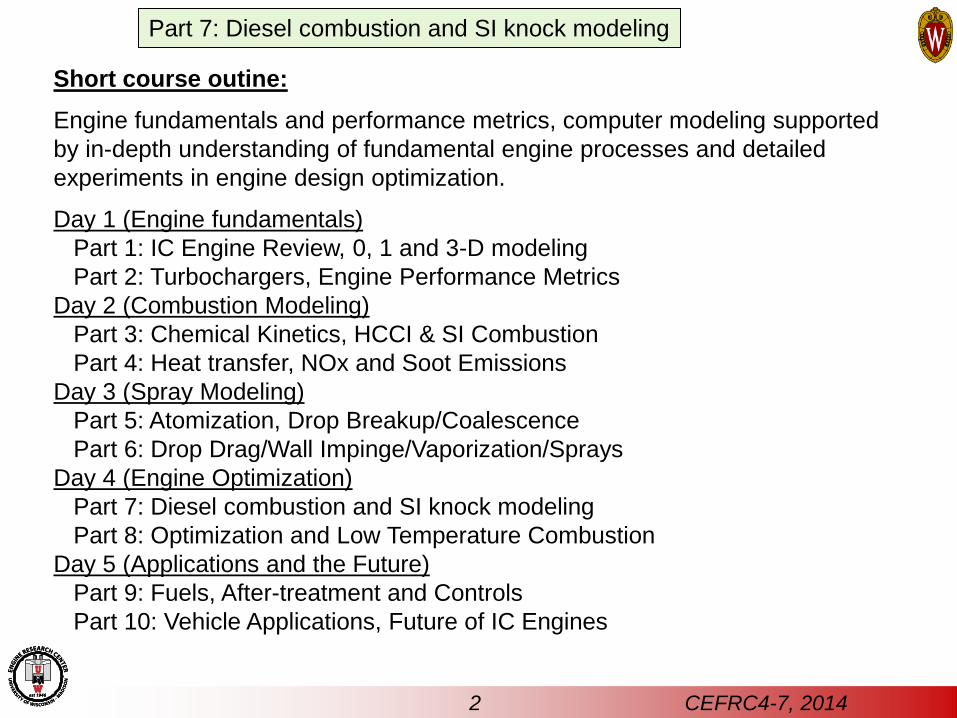
Short course outine:
Engine fundamentals and performance metrics, computer modeling supported
by in-depth understanding of fundamental engine processes and detailed
experiments in engine design optimization.
Day 1 (Engine fundamentals)
Part 1: IC Engine Review, 0, 1 and 3-D modeling
Part 2: Turbochargers, Engine Performance Metrics
Day 2 (Combustion Modeling)
Part 3: Chemical Kinetics, HCCI & SI Combustion
Part 4: Heat transfer, NOx and Soot Emissions
Day 3 (Spray Modeling)
Part 5: Atomization, Drop Breakup/Coalescence
Part 6: Drop Drag/Wall Impinge/Vaporization/Sprays
Day 4 (Engine Optimization)
Part 7: Diesel combustion and SI knock modeling
Part 8: Optimization and Low Temperature Combustion
Day 5 (Applications and the Future)
Part 9: Fuels, After-treatment and Controls
Part 10: Vehicle Applications, Future of IC Engines
2 CEFRC4-7, 2014
Part 7: Diesel combustion and SI knock modeling
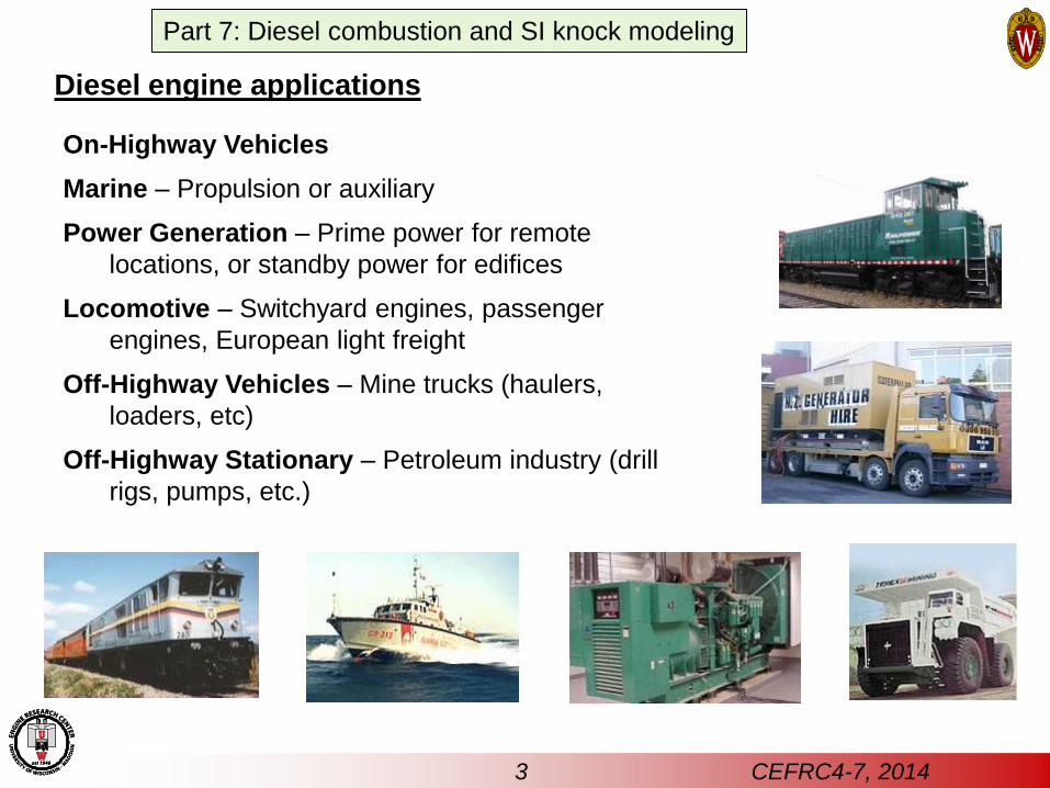
Diesel engine applications
On-Highway Vehicles
Marine – Propulsion or auxiliary
Power Generation – Prime power for remote
locations, or standby power for edifices
Locomotive – Switchyard engines, passenger
engines, European light freight
Off-Highway Vehicles – Mine trucks (haulers,
loaders, etc)
Off-Highway Stationary – Petroleum industry (drill
rigs, pumps, etc.)
3 CEFRC4-7, 2014
Part 7: Diesel combustion and SI knock modeling
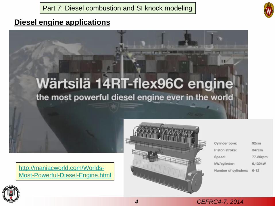
Diesel engine applications
4 CEFRC4-7, 2014
http://maniacworld.com/Worlds-
Most-Powerful-Diesel-Engine.html
Part 7: Diesel combustion and SI knock modeling
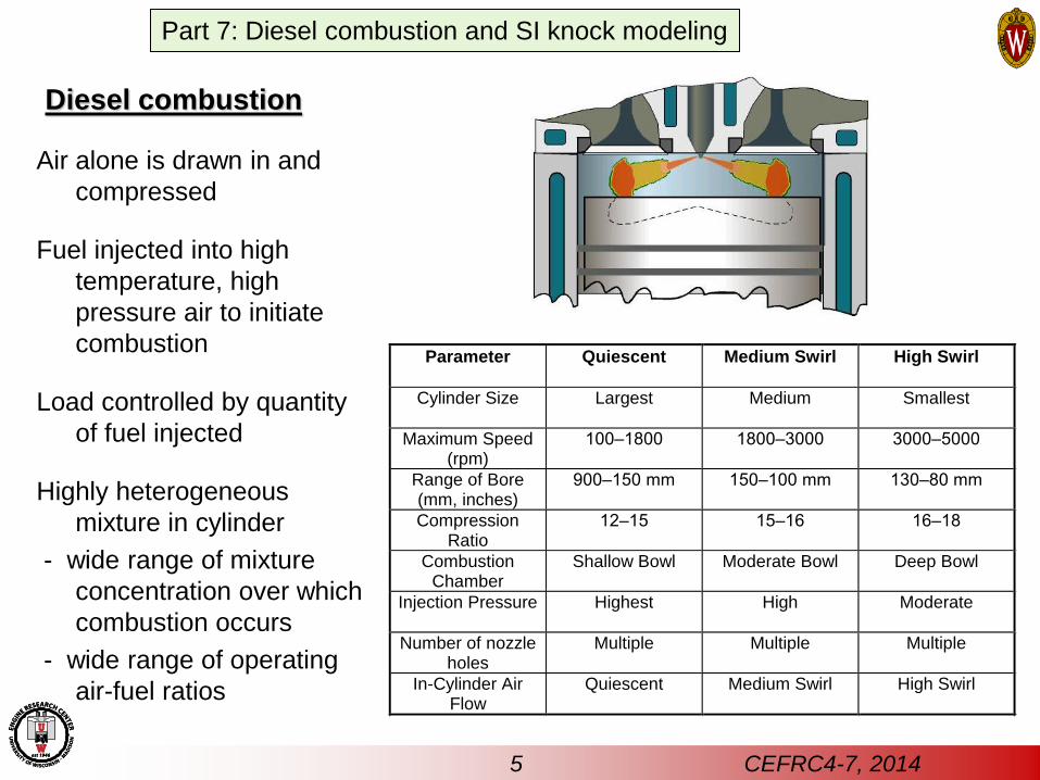
Diesel combustion
Parameter Quiescent Medium Swirl High Swirl
Cylinder Size Largest Medium Smallest
Maximum Speed(rpm)
100–1800 1800–3000 3000–5000
Range of Bore(mm, inches)
900–150 mm 150–100 mm 130–80 mm
CompressionRatio
12–15 15–16 16–18
CombustionChamber
Shallow Bowl Moderate Bowl Deep Bowl
Injection Pressure Highest High Moderate
Number of nozzleholes
Multiple Multiple Multiple
In-Cylinder AirFlow
Quiescent Medium Swirl High Swirl
Air alone is drawn in and
compressed
Fuel injected into high
temperature, high
pressure air to initiate
combustion
Load controlled by quantity
of fuel injected
Highly heterogeneous
mixture in cylinder
- wide range of mixture
concentration over which
combustion occurs
- wide range of operating
air-fuel ratios
5 CEFRC4-7, 2014
Part 7: Diesel combustion and SI knock modeling
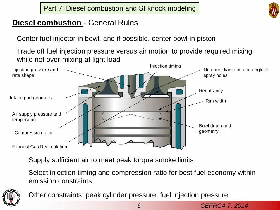
Diesel combustion - General Rules
Center fuel injector in bowl, and if possible, center bowl in piston
Trade off fuel injection pressure versus air motion to provide required mixing
while not over-mixing at light load
Supply sufficient air to meet peak torque smoke limits
Select injection timing and compression ratio for best fuel economy within
emission constraints
Other constraints: peak cylinder pressure, fuel injection pressure
Rim width
Reentrancy
Bowl depth and
geometry
Number, diameter, and angle of
spray holes
Injection pressure and
rate shape
Intake port geometry
Air supply pressure and
temperature
Compression ratio
Exhaust Gas Recirculation
Injection timing
6 CEFRC4-7, 2014
Part 7: Diesel combustion and SI knock modeling
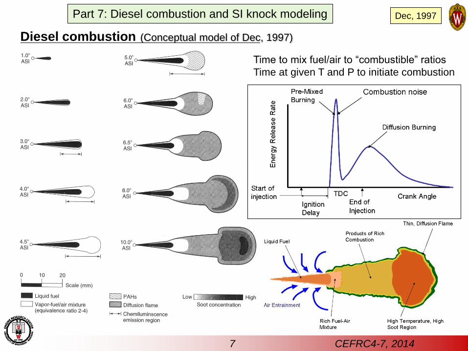
Diesel combustion (Conceptual model of Dec, 1997)
Time to mix fuel/air to “combustible” ratios
Time at given T and P to initiate combustion
Dec, 1997
7 CEFRC4-7, 2014
Part 7: Diesel combustion and SI knock modeling
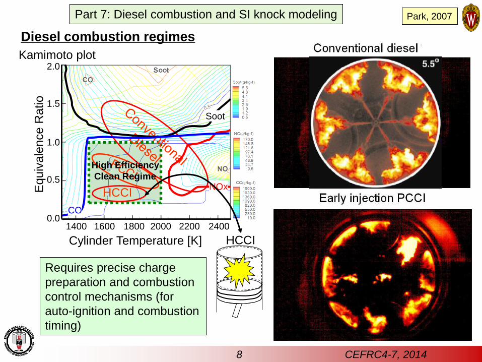
HCCI
High Efficiency
Clean Regime
Cylinder Temperature [K]
Equiv
ale
nce R
atio
0.0
0.5
1.0
1.5
2.0
1400 1600 1800 2000 2200 2400
NOx
Soot
CO
HCCI
Requires precise charge
preparation and combustion
control mechanisms (for
auto-ignition and combustion
timing)
Diesel combustion regimes
Kamimoto plot
Park, 2007
8 CEFRC4-7, 2014
Part 7: Diesel combustion and SI knock modeling
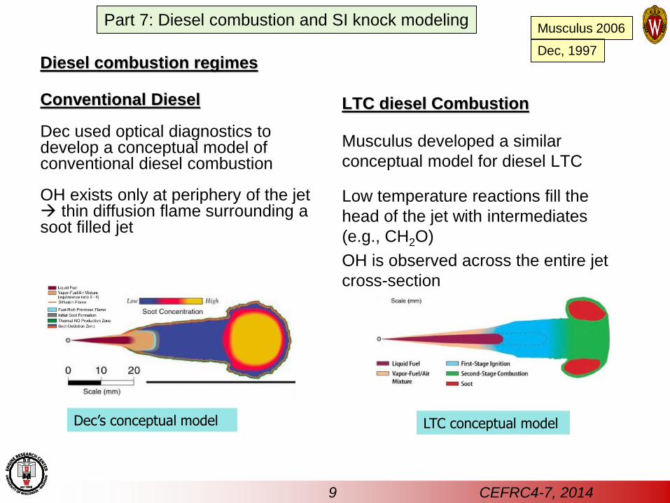
Diesel combustion regimes
Conventional Diesel
Dec used optical diagnostics to develop a conceptual model of conventional diesel combustion
OH exists only at periphery of the jet thin diffusion flame surrounding a soot filled jet
LTC diesel Combustion
Musculus developed a similar
conceptual model for diesel LTC
Low temperature reactions fill the
head of the jet with intermediates
(e.g., CH2O)
OH is observed across the entire jet
cross-section
Dec’s conceptual model LTC conceptual model
Dec, 1997
Musculus 2006
9 CEFRC4-7, 2014
Part 7: Diesel combustion and SI knock modeling
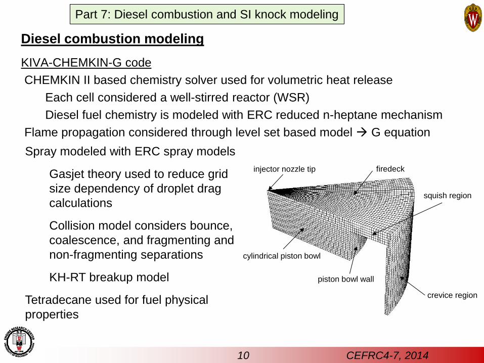
Diesel combustion modeling
KIVA-CHEMKIN-G code
CHEMKIN II based chemistry solver used for volumetric heat release
Each cell considered a well-stirred reactor (WSR)
Diesel fuel chemistry is modeled with ERC reduced n-heptane mechanism
Flame propagation considered through level set based model G equation
cylindrical piston bowl
crevice region
squish region
firedeck injector nozzle tip
piston bowl wall
Spray modeled with ERC spray models
Gasjet theory used to reduce grid
size dependency of droplet drag
calculations
Collision model considers bounce,
coalescence, and fragmenting and
non-fragmenting separations
KH-RT breakup model
Tetradecane used for fuel physical
properties
10 CEFRC4-7, 2014
Part 7: Diesel combustion and SI knock modeling
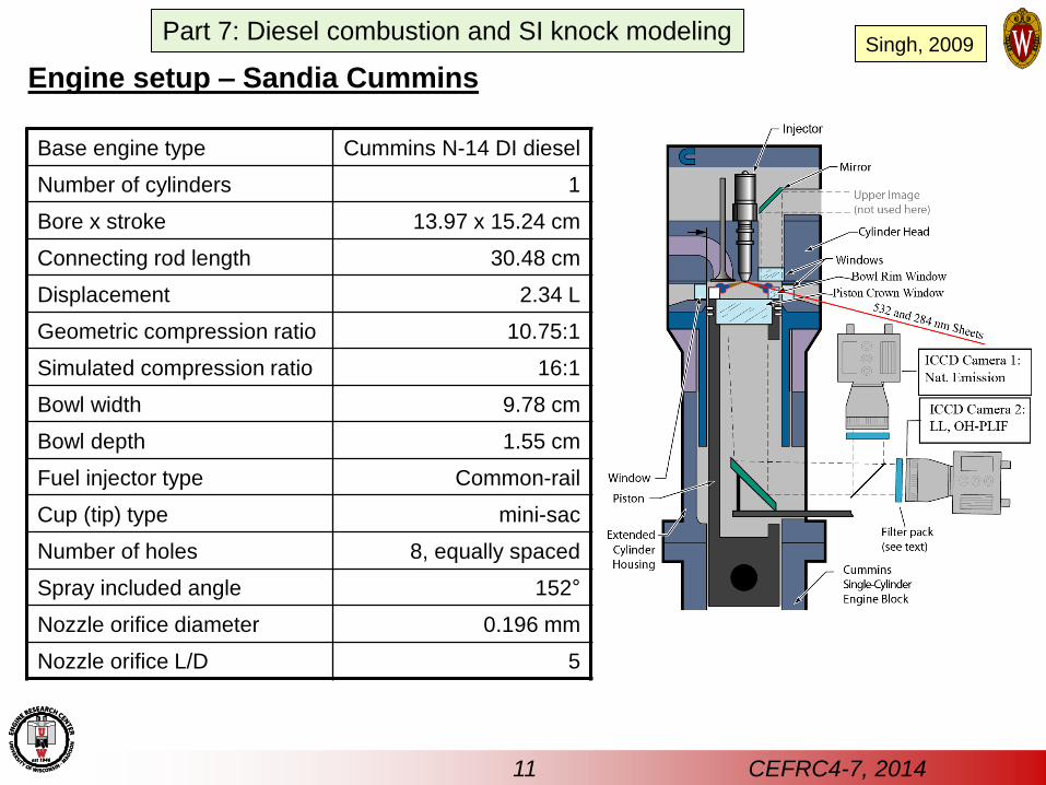
Engine setup – Sandia Cummins
Base engine type Cummins N-14 DI diesel
Number of cylinders 1
Bore x stroke 13.97 x 15.24 cm
Connecting rod length 30.48 cm
Displacement 2.34 L
Geometric compression ratio 10.75:1
Simulated compression ratio 16:1
Bowl width 9.78 cm
Bowl depth 1.55 cm
Fuel injector type Common-rail
Cup (tip) type mini-sac
Number of holes 8, equally spaced
Spray included angle 152°
Nozzle orifice diameter 0.196 mm
Nozzle orifice L/D 5
Singh, 2009
11 CEFRC4-7, 2014
Part 7: Diesel combustion and SI knock modeling
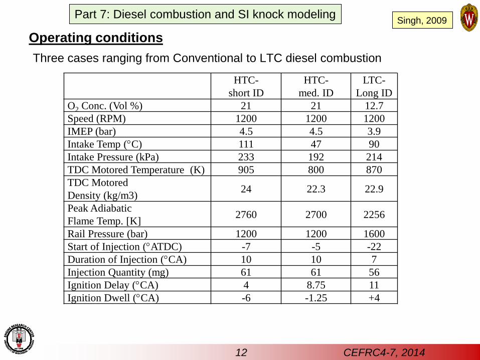
Operating conditions
Three cases ranging from Conventional to LTC diesel combustion
HTC-
short ID
HTC-
med. ID
LTC-
Long ID
O2 Conc. (Vol %) 21 21 12.7
Speed (RPM) 1200 1200 1200
IMEP (bar) 4.5 4.5 3.9
Intake Temp (C) 111 47 90
Intake Pressure (kPa) 233 192 214
TDC Motored Temperature (K) 905 800 870
TDC Motored
Density (kg/m3) 24 22.3 22.9
Peak Adiabatic
Flame Temp. [K] 2760 2700 2256
Rail Pressure (bar) 1200 1200 1600
Start of Injection (ATDC) -7 -5 -22
Duration of Injection (CA) 10 10 7
Injection Quantity (mg) 61 61 56
Ignition Delay (CA) 4 8.75 11
Ignition Dwell (CA) -6 -1.25 +4
12 CEFRC4-7, 2014
Part 7: Diesel combustion and SI knock modeling Singh, 2009
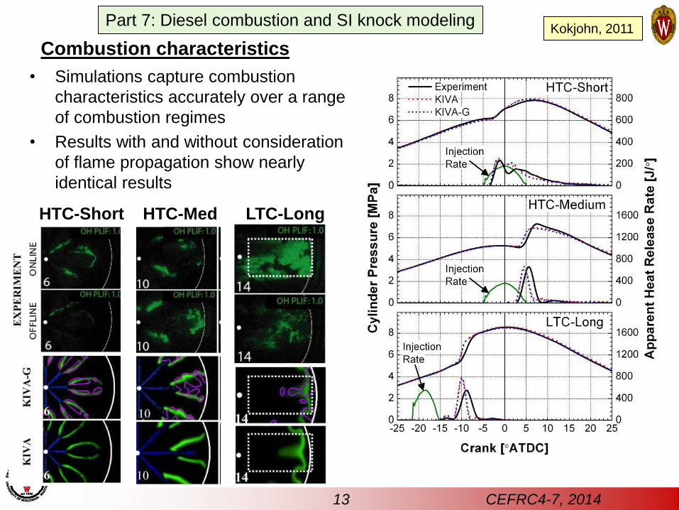
Combustion characteristics
• Simulations capture combustion
characteristics accurately over a range
of combustion regimes
• Results with and without consideration
of flame propagation show nearly
identical results
HTC-Short HTC-Med LTC-Long
Kokjohn, 2011
13 CEFRC4-7, 2014
Part 7: Diesel combustion and SI knock modeling
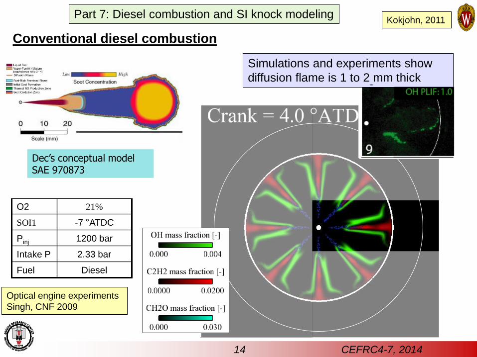
Conventional diesel combustion
-20 -15 -10 -5 0 5 10 15 200
2
4
6
8
10
Experiment
Simulation
Crank [ATDC]
Pre
ssure
[M
Pa]
0
100
200
300
400
500
Heat R
ele
ase R
ate
[J/
]
HTC-Short
injection
profile
O2 21%
SOI1 -7 °ATDC
Pinj 1200 bar
Intake P 2.33 bar
Fuel Diesel
Simulations and experiments show
diffusion flame is 1 to 2 mm thick
Dec’s conceptual model SAE 970873
Optical engine experiments
Singh, CNF 2009
14 CEFRC4-7, 2014
Part 7: Diesel combustion and SI knock modeling Kokjohn, 2011
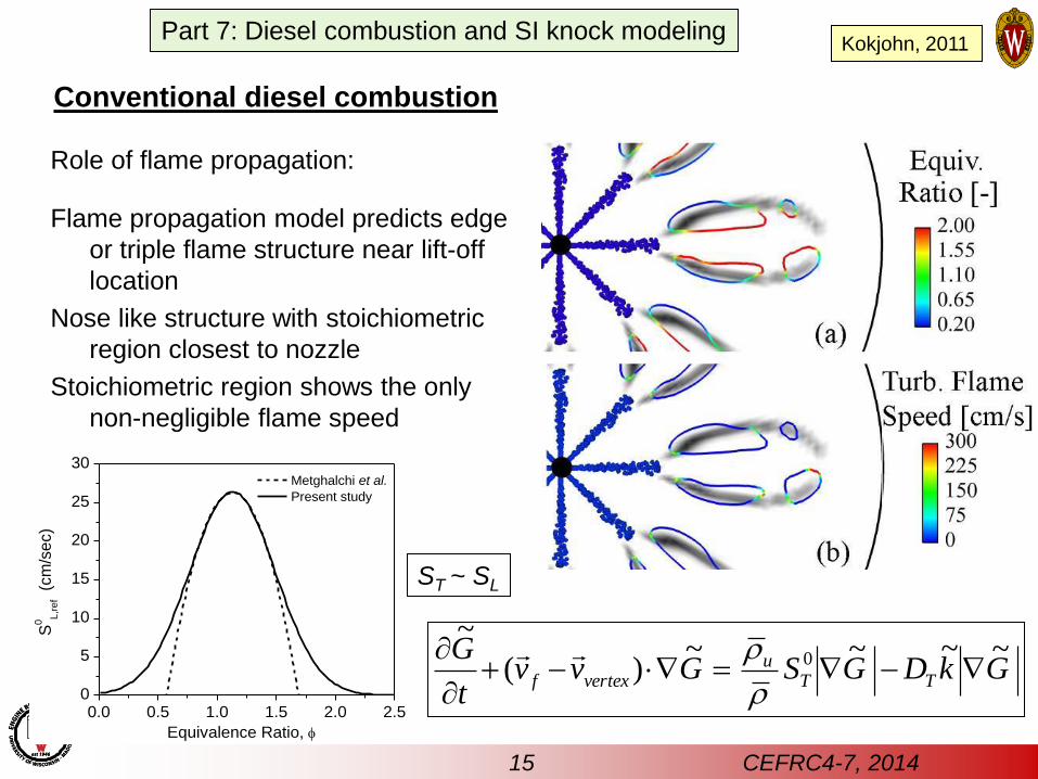
Conventional diesel combustion
Role of flame propagation:
Flame propagation model predicts edge
or triple flame structure near lift-off
location
Nose like structure with stoichiometric
region closest to nozzle
Stoichiometric region shows the only
non-negligible flame speed
GkDGSGvvt
GTT
uvertexf
~~~~)(
~0
0.0 0.5 1.0 1.5 2.0 2.50
5
10
15
20
25
30
Equivalence Ratio,
S0
L,r
ef
(cm
/se
c)
Metghalchi et al.
Present study
ST ~ SL
15 CEFRC4-7, 2014
Part 7: Diesel combustion and SI knock modeling Kokjohn, 2011
-25 -20 -15 -10 -5 0 5 10 15 200
2
4
6
8
10
Experiment
Simulation
Crank [ATDC]
Pre
ssure
[M
Pa]
0
400
800
1200
1600
2000
Heat R
ele
ase R
ate
[J/
]
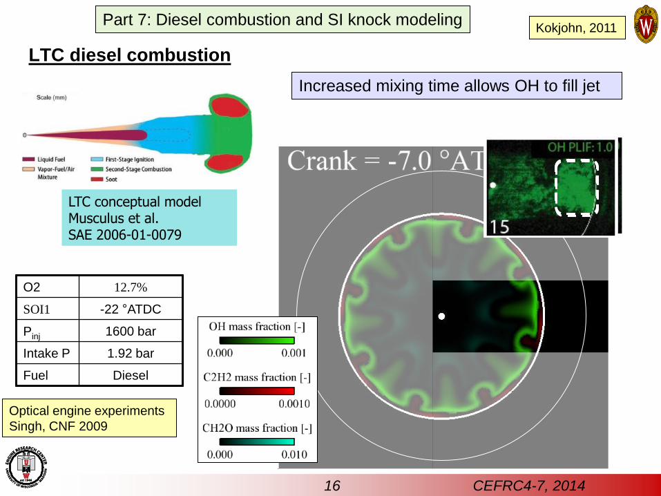
LTC-Early
injection
profile
O2 12.7%
SOI1 -22 °ATDC
Pinj 1600 bar
Intake P 1.92 bar
Fuel Diesel
Increased mixing time allows OH to fill jet
LTC conceptual model Musculus et al. SAE 2006-01-0079
LTC diesel combustion
Optical engine experiments
Singh, CNF 2009
16 CEFRC4-7, 2014
Part 7: Diesel combustion and SI knock modeling Kokjohn, 2011
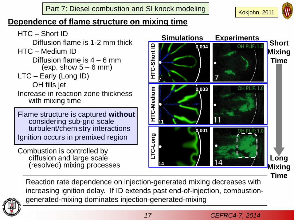
Dependence of flame structure on mixing time
Simulations Experiments
0.003
0.004
0.001
11
7
14
HTC – Short ID
Diffusion flame is 1-2 mm thick
HTC – Medium ID
Diffusion flame is 4 – 6 mm (exp. show 5 – 6 mm)
LTC – Early (Long ID)
OH fills jet
Increase in reaction zone thickness with mixing time
Flame structure is captured without considering sub-grid scale turbulent/chemistry interactions
Ignition occurs in premixed region
Combustion is controlled by diffusion and large scale (resolved) mixing processes
Short
Mixing
Time
Long
Mixing
Time
HT
C-S
ho
rt ID
H
TC
-Me
diu
m
LT
C-L
on
g
Reaction rate dependence on injection-generated mixing decreases with
increasing ignition delay. If ID extends past end-of-injection, combustion-
generated-mixing dominates injection-generated-mixing
17 CEFRC4-7, 2014
Part 7: Diesel combustion and SI knock modeling Kokjohn, 2011
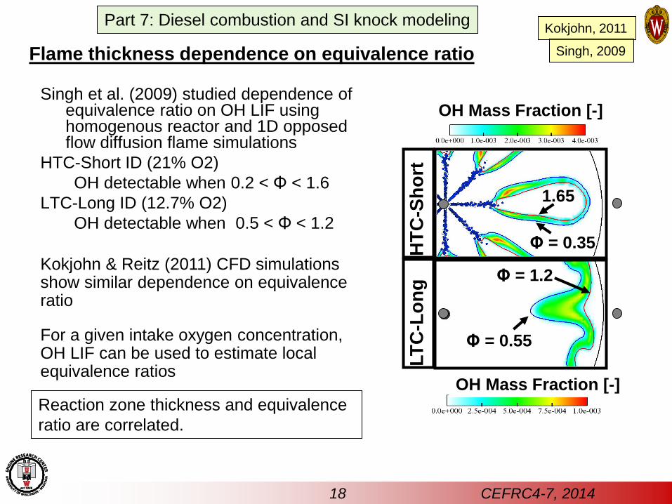
Singh et al. (2009) studied dependence of equivalence ratio on OH LIF using homogenous reactor and 1D opposed flow diffusion flame simulations
HTC-Short ID (21% O2)
OH detectable when 0.2 < Φ < 1.6
LTC-Long ID (12.7% O2)
OH detectable when 0.5 < Φ < 1.2
Φ = 0.35
1.65
Φ = 1.2
Φ = 0.55
HT
C-S
ho
rt
LT
C-L
on
g
OH Mass Fraction [-]
OH Mass Fraction [-]
Kokjohn & Reitz (2011) CFD simulations show similar dependence on equivalence ratio
For a given intake oxygen concentration, OH LIF can be used to estimate local equivalence ratios
Flame thickness dependence on equivalence ratio
Reaction zone thickness and equivalence
ratio are correlated.
18 CEFRC4-7, 2014
Part 7: Diesel combustion and SI knock modeling Kokjohn, 2011
Singh, 2009
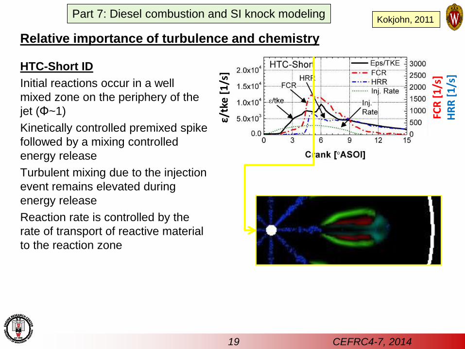
Relative importance of turbulence and chemistry
HTC-Short ID
Initial reactions occur in a well
mixed zone on the periphery of the
jet (Φ~1)
Kinetically controlled premixed spike
followed by a mixing controlled
energy release
Turbulent mixing due to the injection
event remains elevated during
energy release
Reaction rate is controlled by the
rate of transport of reactive material
to the reaction zone
ε/tk
e [
1/s
]
FCR
[1
/s]
HR
R [
1/s
]
19 CEFRC4-7, 2014
Part 7: Diesel combustion and SI knock modeling Kokjohn, 2011
ε/tk
e [
1/s
]
FCR
[1
/s]
HR
R [
1/s
]
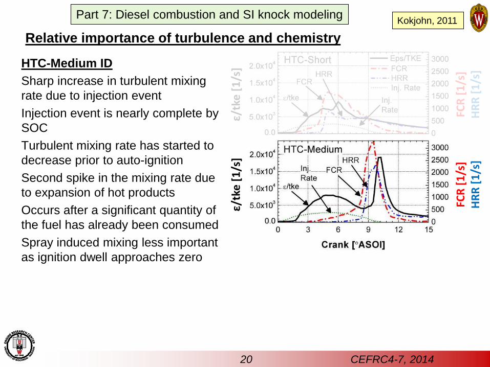
HTC-Medium ID
Sharp increase in turbulent mixing
rate due to injection event
Injection event is nearly complete by
SOC
Turbulent mixing rate has started to
decrease prior to auto-ignition
Second spike in the mixing rate due
to expansion of hot products
Occurs after a significant quantity of
the fuel has already been consumed
Spray induced mixing less important
as ignition dwell approaches zero
ε/tk
e [
1/s
]
FCR
[1
/s]
HR
R [
1/s
]
Relative importance of turbulence and chemistry
20 CEFRC4-7, 2014
Part 7: Diesel combustion and SI knock modeling Kokjohn, 2011
ε/tk
e [
1/s
]
FCR
[1
/s]
HR
R [
1/s
]
ε/tk
e [
1/s
]
FCR
[1
/s]
HR
R [
1/s
]
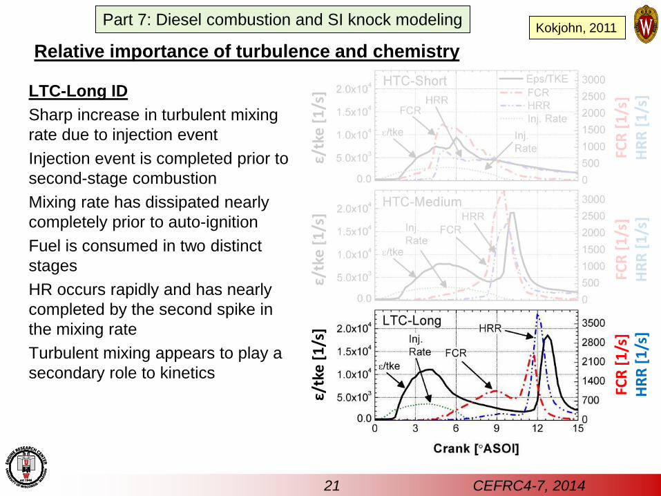
LTC-Long ID
Sharp increase in turbulent mixing
rate due to injection event
Injection event is completed prior to
second-stage combustion
Mixing rate has dissipated nearly
completely prior to auto-ignition
Fuel is consumed in two distinct
stages
HR occurs rapidly and has nearly
completed by the second spike in
the mixing rate
Turbulent mixing appears to play a
secondary role to kinetics
ε/tk
e [
1/s
]
FCR
[1
/s]
HR
R [
1/s
]
Relative importance of turbulence and chemistry
21 CEFRC4-7, 2014
Part 7: Diesel combustion and SI knock modeling Kokjohn, 2011
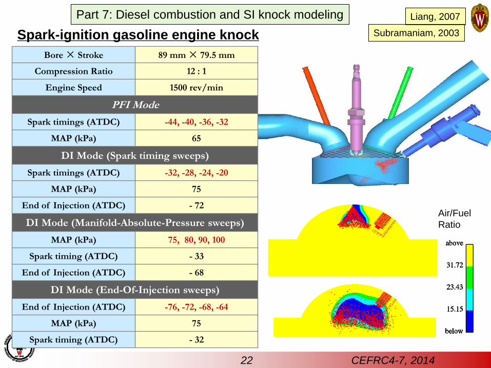
Spark-ignition gasoline engine knock
Bore × Stroke 89 mm × 79.5 mm
Compression Ratio 12 : 1
Engine Speed 1500 rev/min
PFI Mode
Spark timings (ATDC) -44, -40, -36, -32
MAP (kPa) 65
DI Mode (Spark timing sweeps)
Spark timings (ATDC) -32, -28, -24, -20
MAP (kPa) 75
End of Injection (ATDC) - 72
DI Mode (Manifold-Absolute-Pressure sweeps)
MAP (kPa) 75, 80, 90, 100
Spark timing (ATDC) - 33
End of Injection (ATDC) - 68
DI Mode (End-Of-Injection sweeps)
End of Injection (ATDC) -76, -72, -68, -64
MAP (kPa) 75
Spark timing (ATDC) - 32
Air/Fuel
Ratio
Liang, 2007
Subramaniam, 2003
22 CEFRC4-7, 2014
Part 7: Diesel combustion and SI knock modeling
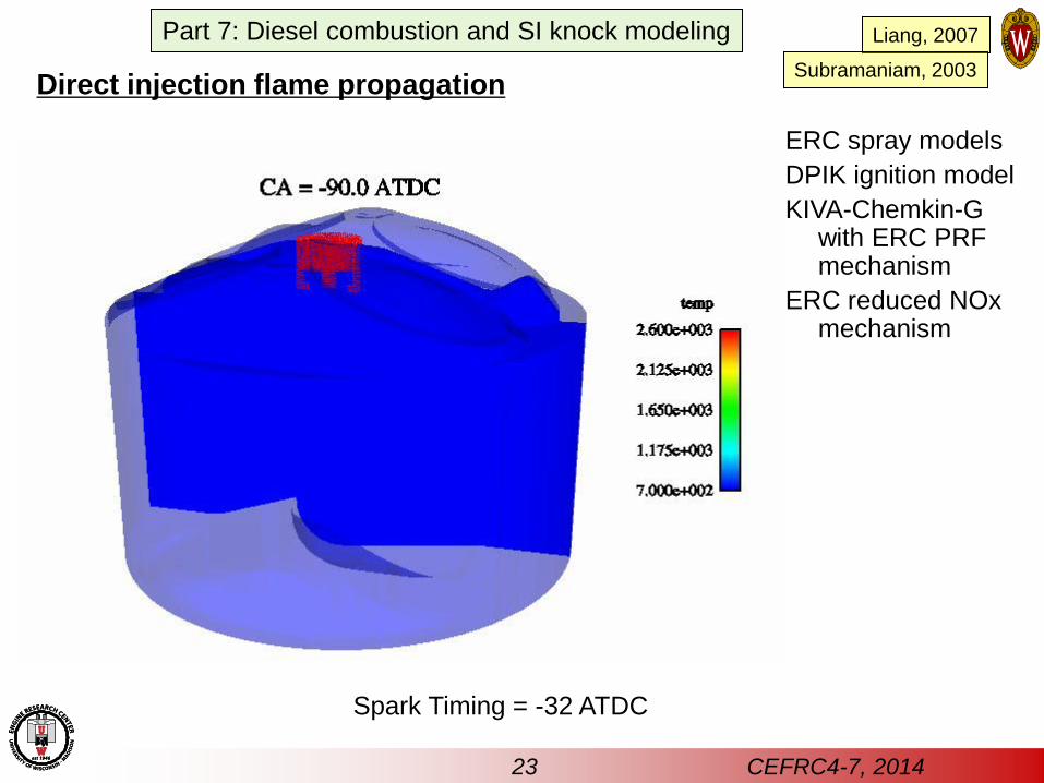
Direct injection flame propagation
Spark Timing = -32 ATDC
ERC spray models
DPIK ignition model
KIVA-Chemkin-G with ERC PRF mechanism
ERC reduced NOx mechanism
23 CEFRC4-7, 2014
Part 7: Diesel combustion and SI knock modeling Liang, 2007
Subramaniam, 2003
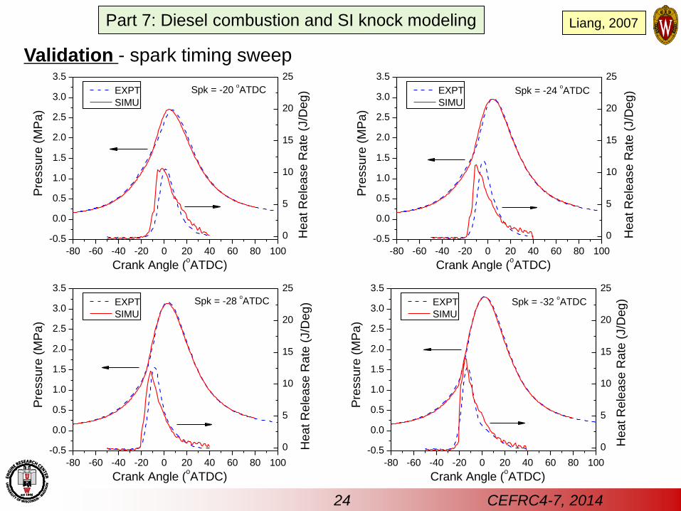
Validation - spark timing sweep
-80 -60 -40 -20 0 20 40 60 80 100
-0.5
0.0
0.5
1.0
1.5
2.0
2.5
3.0
3.5
0
5
10
15
20
25
Pre
ssure
(M
Pa)
Crank Angle (oATDC)
EXPT
SIMU
Hea
t R
ele
ase R
ate
(J/D
eg
)Spk = -20 oATDC
-80 -60 -40 -20 0 20 40 60 80 100
-0.5
0.0
0.5
1.0
1.5
2.0
2.5
3.0
3.5
0
5
10
15
20
25
Pre
ssure
(M
Pa)
Crank Angle (oATDC)
EXPT
SIMU
Spk = -24 oATDC
Hea
t R
ele
ase R
ate
(J/D
eg
)
-80 -60 -40 -20 0 20 40 60 80 100
-0.5
0.0
0.5
1.0
1.5
2.0
2.5
3.0
3.5
0
5
10
15
20
25
Pre
ssure
(M
Pa)
Crank Angle (oATDC)
EXPT
SIMU
Spk = -28 oATDC
Hea
t R
ele
ase R
ate
(J/D
eg
)
-80 -60 -40 -20 0 20 40 60 80 100
-0.5
0.0
0.5
1.0
1.5
2.0
2.5
3.0
3.5
0
5
10
15
20
25
Pre
ssure
(M
Pa)
Crank Angle (oATDC)
EXPT
SIMU
Spk = -32 oATDC
Hea
t R
ele
ase R
ate
(J/D
eg
)
24 CEFRC4-7, 2014
Part 7: Diesel combustion and SI knock modeling Liang, 2007
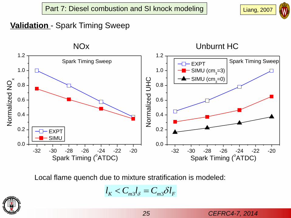
Validation - Spark Timing Sweep
-32 -30 -28 -26 -24 -22 -20
0.0
0.2
0.4
0.6
0.8
1.0
1.2Spark Timing Sweep
No
rma
lize
d N
Ox
Spark Timing (oATDC)
EXPT
SIMU
-32 -30 -28 -26 -24 -22 -20
0.0
0.2
0.4
0.6
0.8
1.0
1.2Spark Timing Sweep
No
rma
lize
d U
HC
Spark Timing (oATDC)
EXPT
SIMU (cm3=3)
SIMU (cm3=0)
3 3K m m Fl C l C l
NOx Unburnt HC
Local flame quench due to mixture stratification is modeled:
25 CEFRC4-7, 2014
Part 7: Diesel combustion and SI knock modeling Liang, 2007
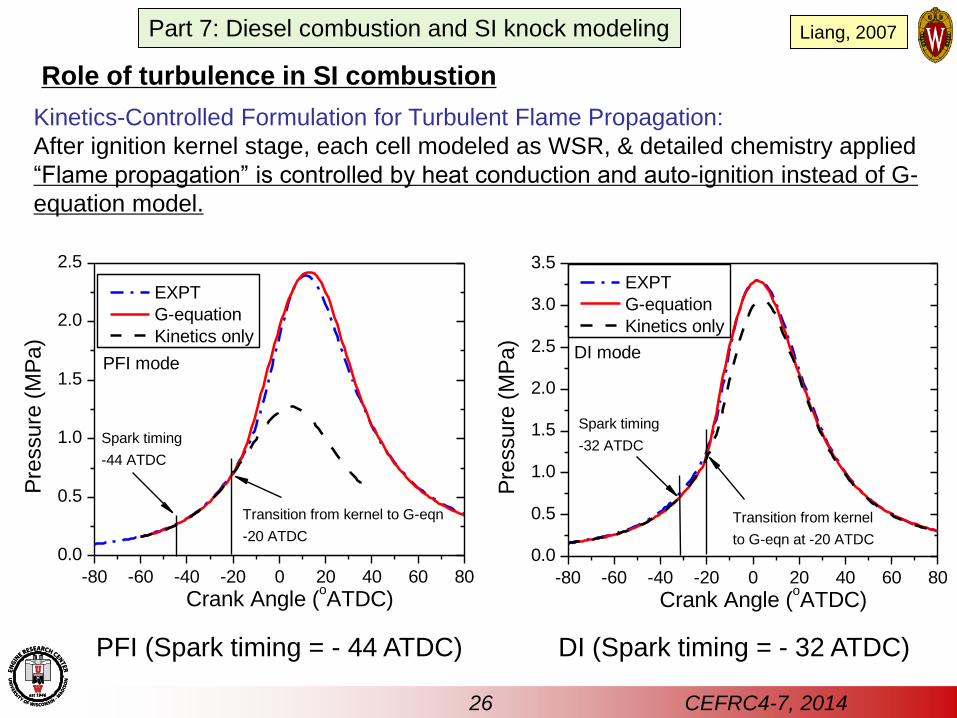
Role of turbulence in SI combustion
Kinetics-Controlled Formulation for Turbulent Flame Propagation:
After ignition kernel stage, each cell modeled as WSR, & detailed chemistry applied
“Flame propagation” is controlled by heat conduction and auto-ignition instead of G-
equation model.
PFI (Spark timing = - 44 ATDC) DI (Spark timing = - 32 ATDC)
-80 -60 -40 -20 0 20 40 60 80
0.0
0.5
1.0
1.5
2.0
2.5
Transition from kernel to G-eqn
-20 ATDC
Pre
ssure
(M
Pa)
Crank Angle (oATDC)
EXPT
G-equation
Kinetics only
Spark timing
-44 ATDC
PFI mode
-80 -60 -40 -20 0 20 40 60 80
0.0
0.5
1.0
1.5
2.0
2.5
3.0
3.5
Transition from kernel
to G-eqn at -20 ATDC
DI mode
Spark timing
-32 ATDC
Pre
ssure
(M
Pa)
Crank Angle (oATDC)
EXPT
G-equation
Kinetics only
26 CEFRC4-7, 2014
Part 7: Diesel combustion and SI knock modeling Liang, 2007
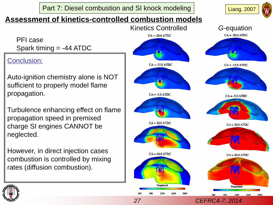
Kinetics Controlled G-equation
Conclusion:
Auto-ignition chemistry alone is NOT
sufficient to properly model flame
propagation.
Turbulence enhancing effect on flame
propagation speed in premixed
charge SI engines CANNOT be
neglected.
However, in direct injection cases
combustion is controlled by mixing
rates (diffusion combustion).
PFI case
Spark timing = -44 ATDC
Assessment of kinetics-controlled combustion models
27 CEFRC4-7, 2014
Part 7: Diesel combustion and SI knock modeling Liang, 2007
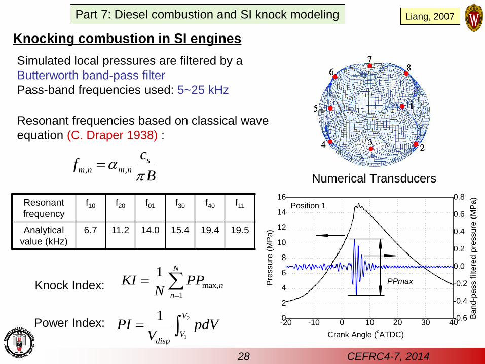
Knocking combustion in SI engines
-20 -10 0 10 20 30 400
2
4
6
8
10
12
14
16
-0.6
-0.4
-0.2
0.0
0.2
0.4
0.6
0.8
Pre
ssure
(M
Pa)
Crank Angle (oATDC)
Position 1
Band-p
ass filt
ere
d p
ressure
(M
Pa)
PPmax
Simulated local pressures are filtered by a
Butterworth band-pass filter
Pass-band frequencies used: 5~25 kHz
Knock Index: max,
1
1 N
n
n
KI PPN
Power Index: 2
1
1 V
Vdisp
PI pdVV
Numerical Transducers
Resonant frequencies based on classical wave
equation (C. Draper 1938) :
Resonant
frequency
f10 f20 f01 f30 f40 f11
Analytical
value (kHz)
6.7 11.2 14.0 15.4 19.4 19.5
, ,s
m n m n
cf
B
28 CEFRC4-7, 2014
Part 7: Diesel combustion and SI knock modeling Liang, 2007
-25 -20 -15 -10 -50.0
0.2
0.4
0.6
0.8
1.0
1.2
0.8
1.0
1.2
1.4
1.6
1.8
2.0
Pow
er
Ind
ex, P
I (M
Pa)
Kno
ck inte
nsity inde
x,
KI (M
Pa)
Spark Timing (CA ATDC)
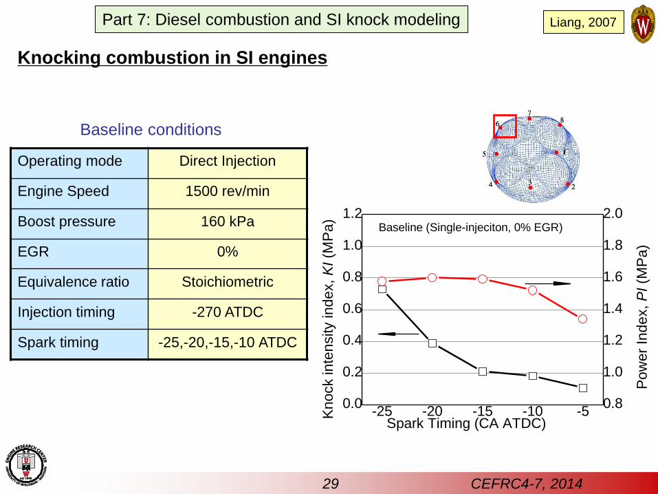
Baseline (Single-injeciton, 0% EGR)
Operating mode Direct Injection
Engine Speed 1500 rev/min
Boost pressure 160 kPa
EGR 0%
Equivalence ratio Stoichiometric
Injection timing -270 ATDC
Spark timing -25,-20,-15,-10 ATDC
Baseline conditions
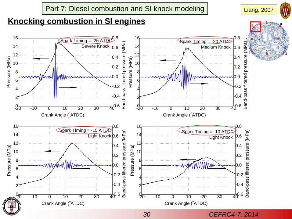
Knocking combustion in SI engines
29 CEFRC4-7, 2014
Part 7: Diesel combustion and SI knock modeling Liang, 2007
-20 -10 0 10 20 30 400
2
4
6
8
10
12
14
16
-0.6
-0.4
-0.2
0.0
0.2
0.4
0.6
0.8Spark Timing = -25 ATDC
Severe Knock
Pre
ssure
(M
Pa)
Crank Angle (oATDC)
Band-p
ass filt
ere
d p
ressure
(M
Pa)
-20 -10 0 10 20 30 400
2
4
6
8
10
12
14
16
-0.6
-0.4
-0.2
0.0
0.2
0.4
0.6
0.8
Pre
ssure
(M
Pa)
Crank Angle (oATDC)
Band-p
ass filt
ere
d p
ressure
(M
Pa) Spark Timing = -20 ATDC
Medium Knock
-20 -10 0 10 20 30 400
2
4
6
8
10
12
14
16
-0.6
-0.4
-0.2
0.0
0.2
0.4
0.6
0.8
Pre
ssure
(M
Pa)
Crank Angle (oATDC)
Spark Timing = -15 ATDC
Light Knock
Band-p
ass filt
ere
d p
ressure
(M
Pa)
-20 -10 0 10 20 30 400
2
4
6
8
10
12
14
16
-0.6
-0.4
-0.2
0.0
0.2
0.4
0.6
0.8
Pre
ssure
(M
Pa)
Crank Angle (oATDC)
Spark Timing = -10 ATDC
Light Knock
Band-p
ass filt
ere
d p
ressure
(M
Pa)
Knocking combustion in SI engines
30 CEFRC4-7, 2014
Part 7: Diesel combustion and SI knock modeling Liang, 2007
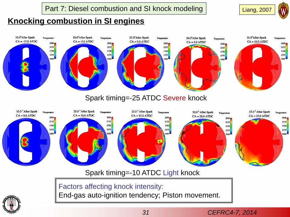
Factors affecting knock intensity:
End-gas auto-ignition tendency; Piston movement.
Spark timing=-10 ATDC Light knock
Spark timing=-25 ATDC Severe knock
Knocking combustion in SI engines
31 CEFRC4-7, 2014
Part 7: Diesel combustion and SI knock modeling Liang, 2007
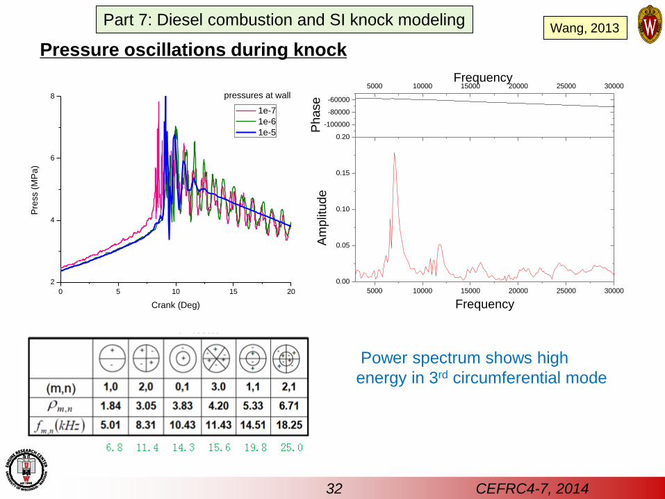
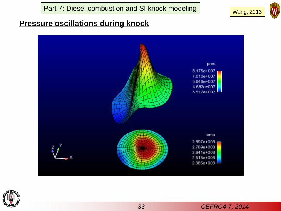
Pressure oscillations during knock
0 5 10 15 20
2
4
6
8
Pre
ss (
MP
a)
Crank (Deg)
1e-7
1e-6
1e-5
pressures at wall
5000 10000 15000 20000 25000 30000
0.00
0.05
0.10
0.15
0.20
Frequency
Am
plit
ude
-100000
-80000
-60000
5000 10000 15000 20000 25000 30000Frequency
Phase
Power spectrum shows high
energy in 3rd circumferential mode
Wang, 2013
32 CEFRC4-7, 2014
Part 7: Diesel combustion and SI knock modeling
Pressure oscillations during knock
33 CEFRC4-7, 2014
Part 7: Diesel combustion and SI knock modeling Wang, 2013
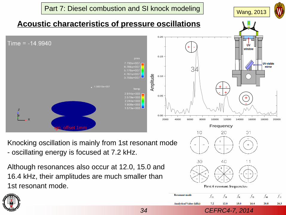
34
Acoustic characteristics of pressure oscillations
ign. offset 1mm
2000 4000 6000 8000 10000 12000 14000 16000 18000 20000
0.00
0.05
0.10
0.15
0.20
Frequency
Am
plitu
de
+ -
+ -
- + +
-
resonance modes from equation [Draper]
Knocking oscillation is mainly from 1st resonant mode
- oscillating energy is focused at 7.2 kHz.
Although resonances also occur at 12.0, 15.0 and
16.4 kHz, their amplitudes are much smaller than
1st resonant mode.
34 CEFRC4-7, 2014
Part 7: Diesel combustion and SI knock modeling Wang, 2013
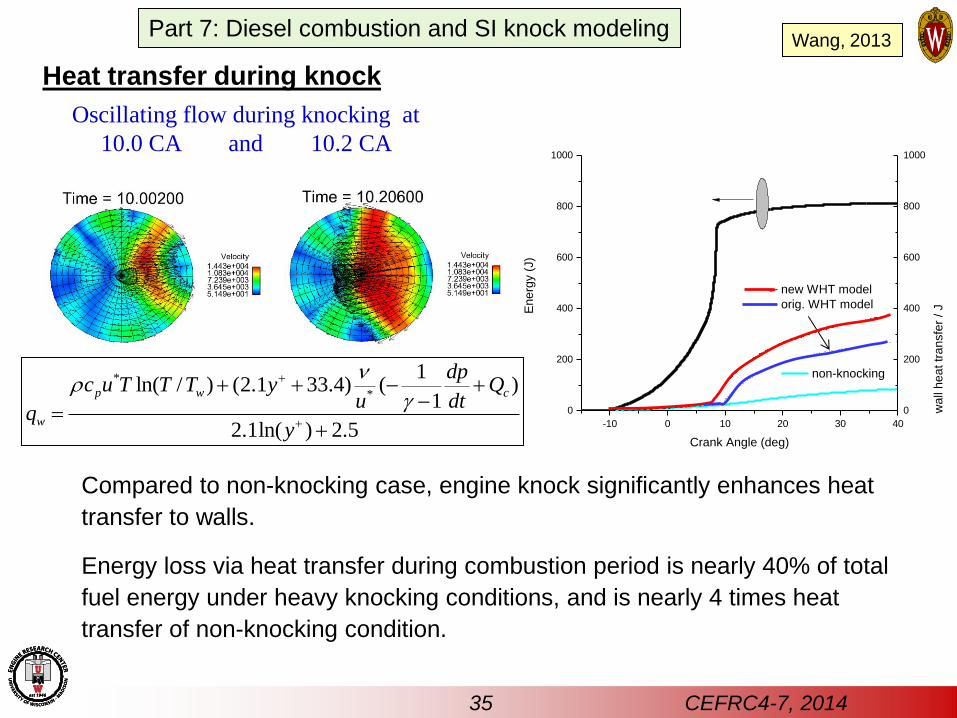
Heat transfer during knock
Compared to non-knocking case, engine knock significantly enhances heat
transfer to walls.
Energy loss via heat transfer during combustion period is nearly 40% of total
fuel energy under heavy knocking conditions, and is nearly 4 times heat
transfer of non-knocking condition.
Oscillating flow during knocking at
10.0 CA and 10.2 CA
*
*
1ln( / ) (2.1 33.4) ( )
1
2.1ln( ) 2.5
p w c
w
dpc u T T T y Q
u dtq
y
-10 0 10 20 30 40
0
200
400
600
800
1000
wa
ll h
ea
t tr
an
sfe
r / JEn
erg
y (
J)
Crank Angle (deg)
non-knocking
0
200
400
600
800
1000
new WHT model
orig. WHT model
35 CEFRC4-7, 2014
Part 7: Diesel combustion and SI knock modeling Wang, 2013
36 CEFRC4-7, 2014
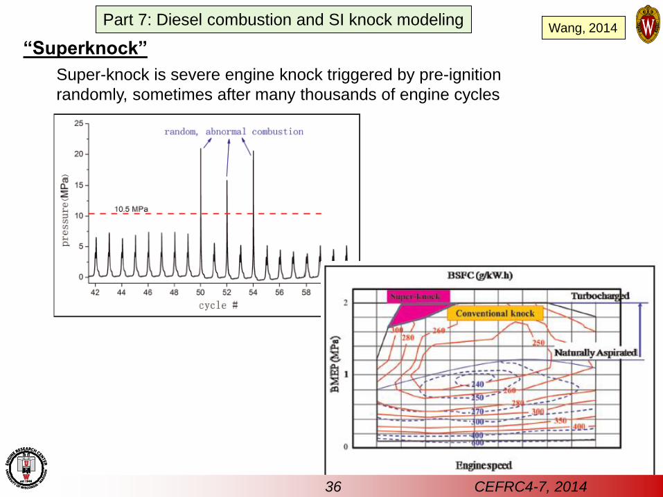
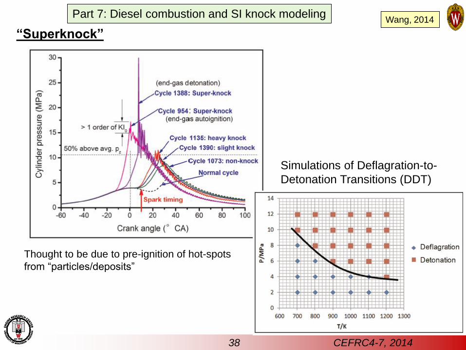
“Superknock”
Super-knock is severe engine knock triggered by pre-ignition
randomly, sometimes after many thousands of engine cycles
Part 7: Diesel combustion and SI knock modeling Wang, 2014
37 CEFRC4-7, 2014
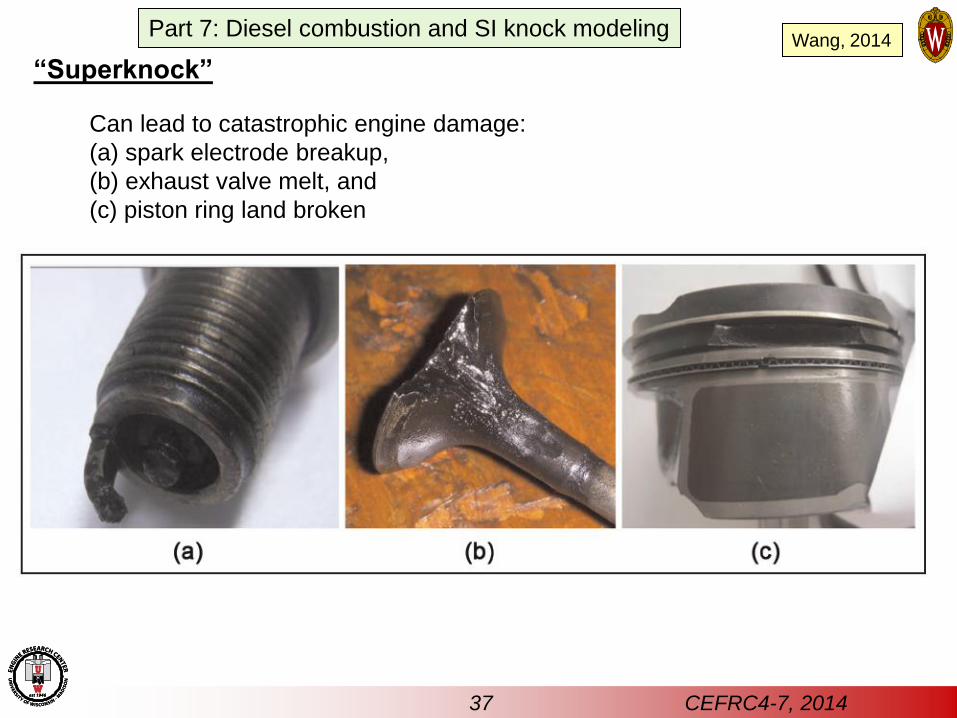
“Superknock”
Can lead to catastrophic engine damage:
(a) spark electrode breakup,
(b) exhaust valve melt, and
(c) piston ring land broken
Part 7: Diesel combustion and SI knock modeling Wang, 2014
38 CEFRC4-7, 2014
Thought to be due to pre-ignition of hot-spots
from “particles/deposits”
“Superknock”
Simulations of Deflagration-to-
Detonation Transitions (DDT)
Part 7: Diesel combustion and SI knock modeling Wang, 2014
39 CEFRC4-7, 2014
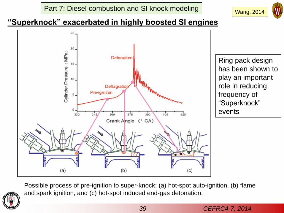
“Superknock” exacerbated in highly boosted SI engines
Possible process of pre-ignition to super-knock: (a) hot-spot auto-ignition, (b) flame
and spark ignition, and (c) hot-spot induced end-gas detonation.
Ring pack design
has been shown to
play an important
role in reducing
frequency of
“Superknock”
events
Part 7: Diesel combustion and SI knock modeling Wang, 2014
Summary
CFD modeling is capable of describing both diesel and spark-ignition
combustion characteristics over a wide range of conditions.
Diesel (mixing-controlled) and premixed combustion is adequately represented
without requiring sub-grid-scale turbulence-chemistry interactions to be
modeled. The effect of turbulence on combustion is modeled satisfactorily
using an integrated G-equation-based combustion model with detailed
chemical kinetics (CHEMKIN).
Very similar results are achieved with and without consideration of flame
propagation for diesel combustion:
- G-equation flame propagation model does reveal edge flame at lift-off
location (not observed with the kinetics-only calculation)
Flame-propagation-dominated premixed charge spark-ignition engine
combustion requires specification of turbulent flame speed in the model.
The G-equation-CHEMKIN model allows all combustion regimes to be modeled
(GAMUT: G-equation for All Mixtures – a Universal Turbulent combustion
model – Tan & Reitz, 2004, Reitz & Sun, 2009).
Integration with chemistry model allows model to predict both diesel ignition
and SI engine knock processes.
40 CEFRC4-7, 2014
Part 7: Diesel combustion and SI knock modeling Tan, 2004
Reitz, 2009