Embed Size (px)
Citation preview
Reciprocating Internal Combustion Engines
Prof. Rolf D. Reitz
Engine Research Center
University of Wisconsin-Madison
2014 Princeton-CEFRC
Summer School on Combustion
Course Length: 15 hrs
(Mon.- Fri., June 23 – 27, 2014)
1 CEFRC2-3, 2014
Copyright ©2014 by Rolf D. Reitz.
This material is not to be sold, reproduced or distributed without
prior written permission of the owner, Rolf D. Reitz.
Part 3: Chemical Kinetics, HCCI & SI Combustion
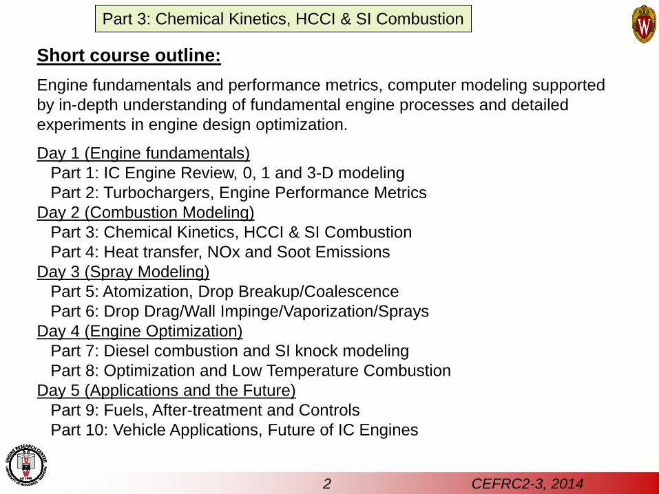
Short course outline:
Engine fundamentals and performance metrics, computer modeling supported
by in-depth understanding of fundamental engine processes and detailed
experiments in engine design optimization.
Day 1 (Engine fundamentals)
Part 1: IC Engine Review, 0, 1 and 3-D modeling
Part 2: Turbochargers, Engine Performance Metrics
Day 2 (Combustion Modeling)
Part 3: Chemical Kinetics, HCCI & SI Combustion
Part 4: Heat transfer, NOx and Soot Emissions
Day 3 (Spray Modeling)
Part 5: Atomization, Drop Breakup/Coalescence
Part 6: Drop Drag/Wall Impinge/Vaporization/Sprays
Day 4 (Engine Optimization)
Part 7: Diesel combustion and SI knock modeling
Part 8: Optimization and Low Temperature Combustion
Day 5 (Applications and the Future)
Part 9: Fuels, After-treatment and Controls
Part 10: Vehicle Applications, Future of IC Engines
Part 3: Chemical Kinetics, HCCI & SI Combustion
2 CEFRC2-3, 2014
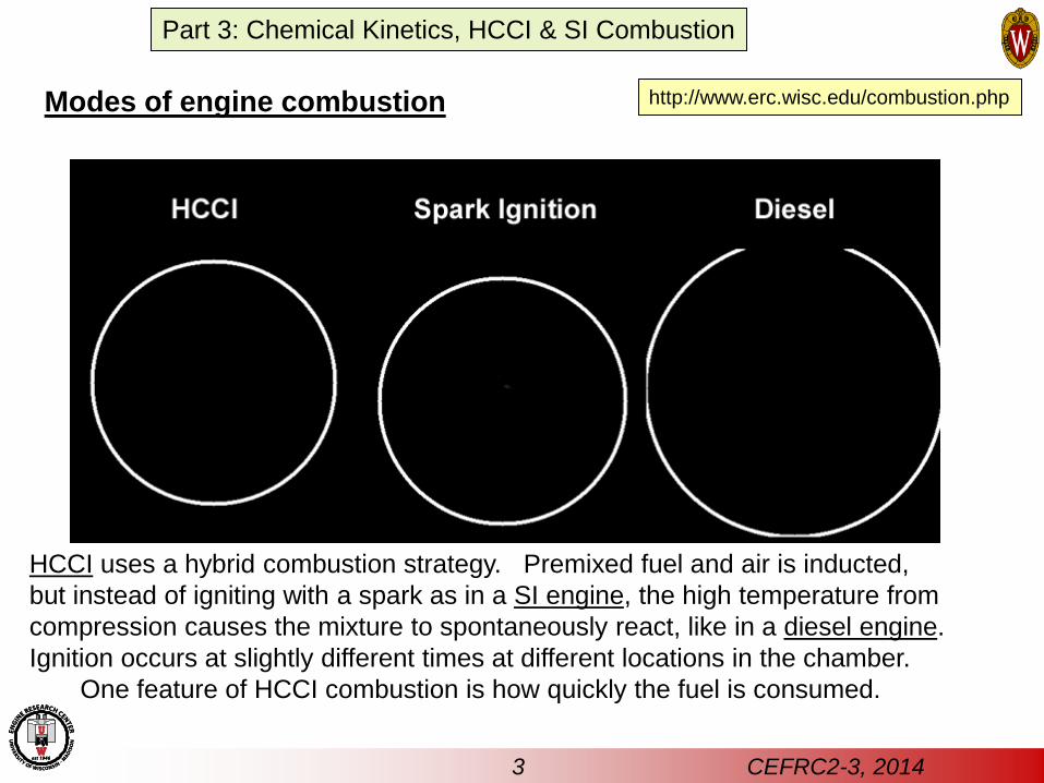
Modes of engine combustion http://www.erc.wisc.edu/combustion.php
HCCI uses a hybrid combustion strategy. Premixed fuel and air is inducted,
but instead of igniting with a spark as in a SI engine, the high temperature from
compression causes the mixture to spontaneously react, like in a diesel engine.
Ignition occurs at slightly different times at different locations in the chamber.
One feature of HCCI combustion is how quickly the fuel is consumed.
3 CEFRC2-3, 2014
Part 3: Chemical Kinetics, HCCI & SI Combustion
4 CEFRC2-3, 2014
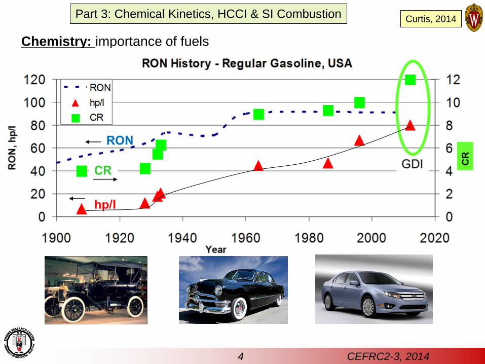
Chemistry: importance of fuels
Part 3: Chemical Kinetics, HCCI & SI Combustion Curtis, 2014
5 CEFRC2-3, 2014
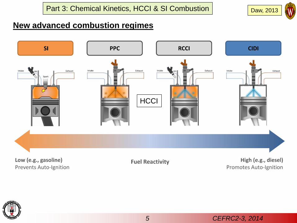
New advanced combustion regimes
HCCI
Part 3: Chemical Kinetics, HCCI & SI Combustion Daw, 2013
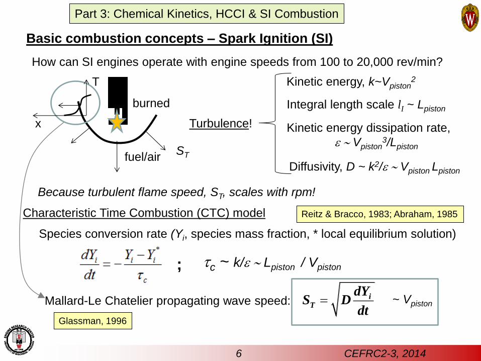
Basic combustion concepts – Spark Ignition (SI)
Characteristic Time Combustion (CTC) model
How can SI engines operate with engine speeds from 100 to 20,000 rev/min?
Because turbulent flame speed, ST, scales with rpm!
ST
tc ~ k/e ~ Lpiston / Vpiston
Kinetic energy, k~Vpiston2
Integral length scale lI ~ Lpiston
Kinetic energy dissipation rate,
e ~ Vpiston3/Lpiston
Species conversion rate (Yi, species mass fraction, * local equilibrium solution)
Diffusivity, D ~ k2/e ~ Vpiston Lpiston
Turbulence!
;
fuel/air
burned
Mallard-Le Chatelier propagating wave speed: ~ Vpiston
T
x
iT
dYS D
dtGlassman, 1996
Reitz & Bracco, 1983; Abraham, 1985
6 CEFRC2-3, 2014
Part 3: Chemical Kinetics, HCCI & SI Combustion
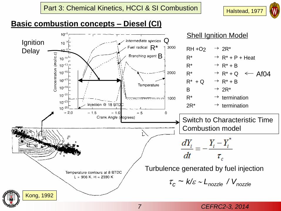
Basic combustion concepts – Diesel (CI)
Shell Ignition Model
RH +O2 2R*
R* R* + P + Heat
R* R* + B
R* R* + Q
R* + Q R* + B
B 2R*
R* termination
2R* termination
Af04
R*
B
Q
Switch to Characteristic Time
Combustion model
Ignition
Delay
tc ~ k/e ~ Lnozzle / Vnozzle
Turbulence generated by fuel injection
Kong, 1992
Halstead, 1977
7 CEFRC2-3, 2014
Part 3: Chemical Kinetics, HCCI & SI Combustion
8 CEFRC2-3, 2014
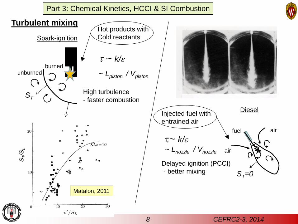
Turbulent mixing
ST
Hot products with
Cold reactants Spark-ignition
t ~ k/e
~ Lpiston / Vpiston
High turbulence
- faster combustion
burned unburned
ST/S
L
Matalon, 2011
Part 3: Chemical Kinetics, HCCI & SI Combustion
Diesel
fuel
air
air
Delayed ignition (PCCI)
- better mixing ST=0
t~ k/e ~ Lnozzle / Vnozzle
Injected fuel with
entrained air
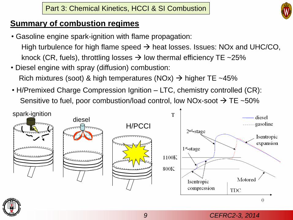
• Diesel engine with spray (diffusion) combustion:
Rich mixtures (soot) & high temperatures (NOx) higher TE ~45%
• Gasoline engine spark-ignition with flame propagation:
High turbulence for high flame speed heat losses. Issues: NOx and UHC/CO,
knock (CR, fuels), throttling losses low thermal efficiency TE ~25%
spark-ignition
• H/Premixed Charge Compression Ignition – LTC, chemistry controlled (CR):
Sensitive to fuel, poor combustion/load control, low NOx-soot TE ~50%
H/PCCI diesel
Summary of combustion regimes
9 CEFRC2-3, 2014
Part 3: Chemical Kinetics, HCCI & SI Combustion
10 CEFRC2-3, 2014
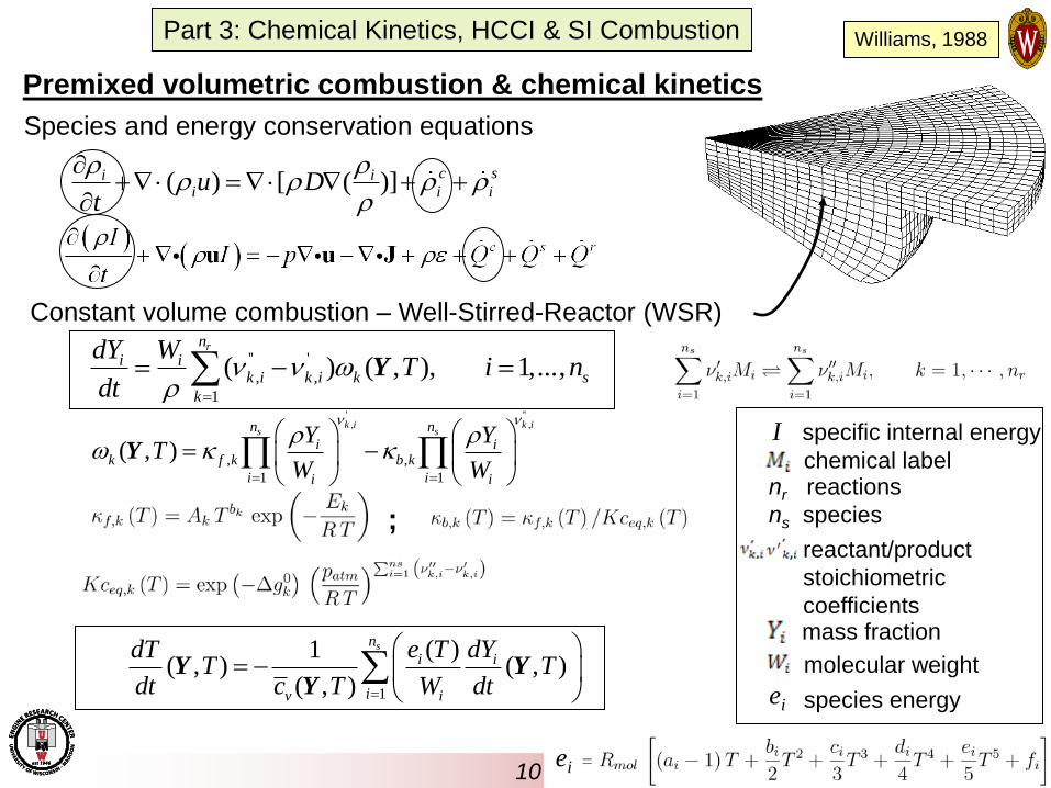
Premixed volumetric combustion & chemical kinetics
Species and energy conservation equations
Constant volume combustion – Well-Stirred-Reactor (WSR)
;
nr reactions
ns species
chemical label
mass fraction
molecular weight
species energy
reactant/product
stoichiometric
coefficients
I specific internal energy
( ) [ ( )] c si ii i iu D
t
Williams, 1988
'' '
, ,
1
( ) ( , ), 1,...,rn
i ik i k i k s
k
dY WT i n
dt
Y
' '', ,
, ,
1 1
( , )
k i k is sn n
i ik f k b k
i ii i
Y YT
W W
Y
1
( )1( , ) ( , )
( , )
sn
i i
iv i
e T dYdTT T
dt c T W dt
Y Y
Y
ei
ei
Part 3: Chemical Kinetics, HCCI & SI Combustion
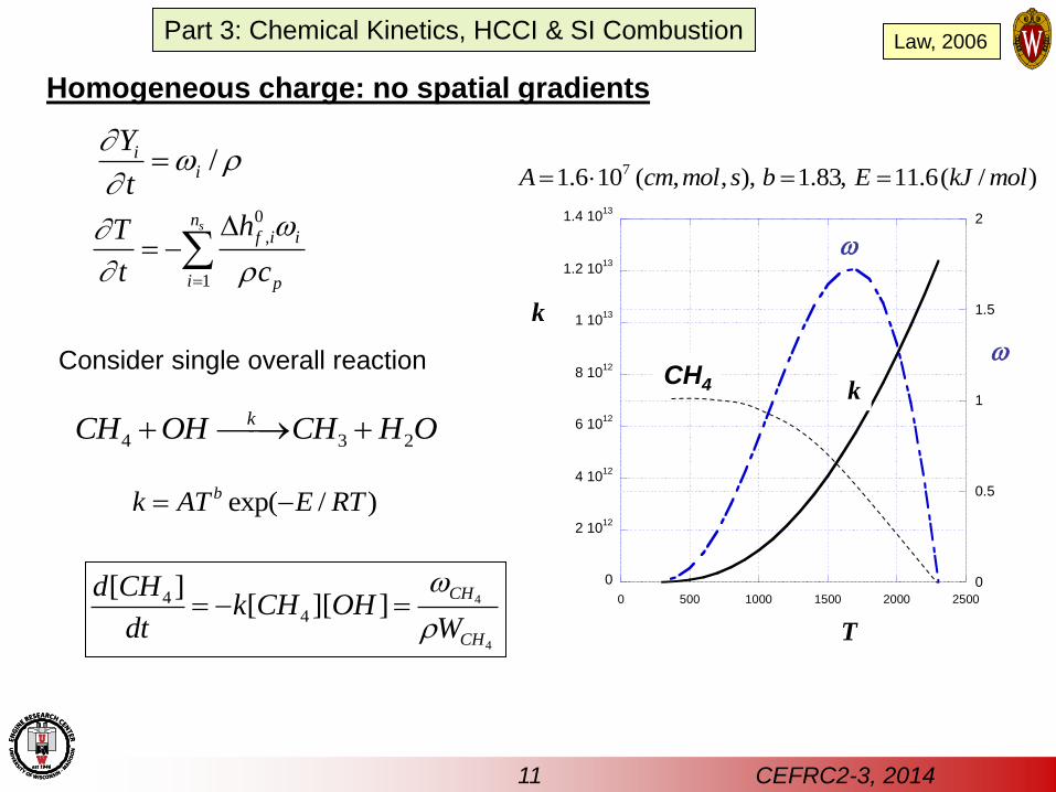
Homogeneous charge: no spatial gradients
11 CEFRC2-3, 2014
/ii
Y
t
Consider single overall reaction
0
,
1
snf i i
i p
hT
t c
4 3 2
kCH OH CH H O
exp( / )bk AT E RT
71.6 10 ( , , ), 1.83, 11.6( / )A cm mol s b E kJ mol
4
4
44
[ ][ ][ ]
CH
CH
d CHk CH OH
dt W
0
2 1012
4 1012
6 1012
8 1012
1 1013
1.2 1013
1.4 1013
0
0.5
1
1.5
2
0 500 1000 1500 2000 2500
T
k
k
CH4
Part 3: Chemical Kinetics, HCCI & SI Combustion Law, 2006
0
0.1
0.2
0.3
0.4
0.5
0.6
0 0.2 0.4 0.6 0.8 1
F(U
)=U
m+
1(1
-U)m
U
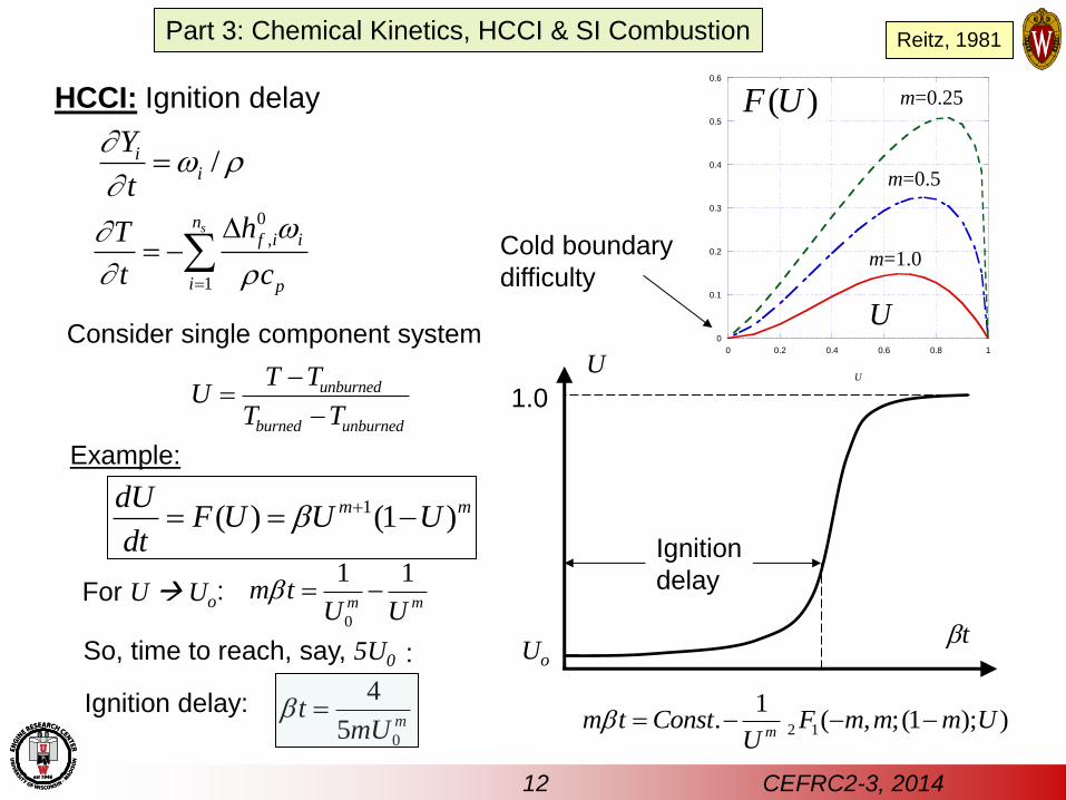
HCCI: Ignition delay
bt
U
1.0
Uo
Ignition
delay
12 CEFRC2-3, 2014
/ii
Y
t
1( ) (1 )m mdUF U U U
dtb
Consider single component system
unburned
burned unburned
T TU
T T
Example:
For U Uo 0
1 1m m
m tU U
b :
So, time to reach, say, 5U0 :
Ignition delay:
0
4
5 mt
mUb
2 1
1. ( , ;(1 ); )
mm t Const F m m m U
Ub
m=0.25
m=0.5
m=1.0
( )F U
U
Cold boundary
difficulty
0
,
1
snf i i
i p
hT
t c
Part 3: Chemical Kinetics, HCCI & SI Combustion Reitz, 1981
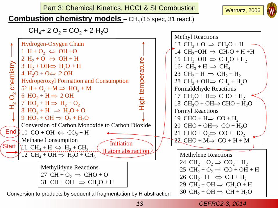
Combustion chemistry models – CH4 (15 spec, 31 react.)
Hydrogen-Oxygen Chain
1 H + O2 OH +O
2 H2 + O OH + H
3 H2 + OH H2O + H
4 H2O + O 2 OH
Hydroperoxyl Formation and Consumption
5b H + O2 + M HO2 + M
6 HO2 + H 2 OH
7 HO2 + H H2 + O2
8 HO2 + H H2O + O
9 HO2 + OH O2 + H2O
Conversion of Carbon Monoxide to Carbon Dioxide
10 CO + OH CO2 + H
Methane Consumption
11 CH4 + H H2 + CH3
12 CH4 + OH H2O + CH3
Methyl Reactions
13 CH3 + O CH2O + H
14 CH3+OH CH2O + H +H
15 CH3+OH CH2O + H2
16c CH3 + H CH4
23 CH3 + H CH2 + H2
28 CH3 + OH CH2 + H2O
Formaldehyde Reactions
17 CH2O + H CHO + H2
18 CH2O + OH CHO + H2O
Formyl Reactions
19 CHO + H CO + H2
20 CHO + OH CO + H2O
21 CHO + O2 CO + HO2
22 CHO + M CO + H + M
Methylene Reactions
24 CH2 + O2 CO2 + H2
25 CH2 + O2 CO + OH + H
26 CH2 +H CH + H2
29 CH2 + OH CH2O + H
30 CH2 + OH CH + H2O
Methylidyne Reactions
27 CH + O2 CHO + O
31 CH + OH CH2O + H
CH4+ 2 O2 = CO2 + 2 H2O
H2 O
2 c
hem
istr
y
Conversion to products by sequential fragmentation by H abstraction
Hig
h t
em
pera
ture
End
Initiation
H atom abstraction Start
13 CEFRC2-3, 2014
Part 3: Chemical Kinetics, HCCI & SI Combustion Warnatz, 2006
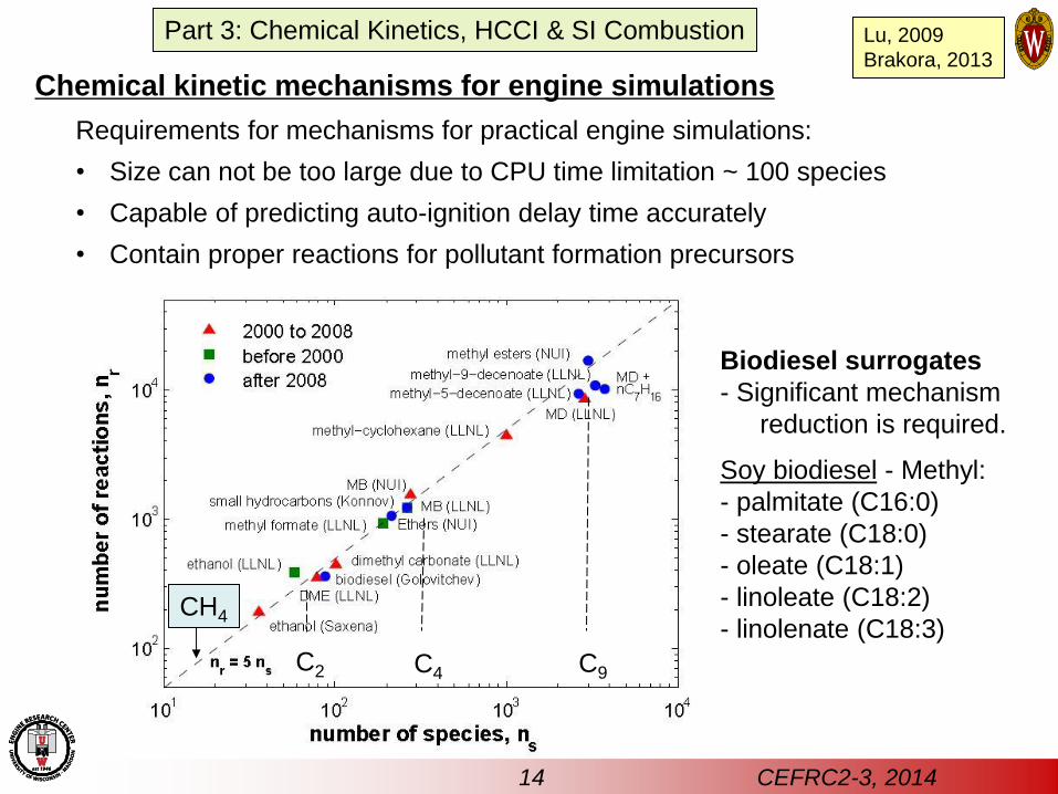
Chemical kinetic mechanisms for engine simulations
Requirements for mechanisms for practical engine simulations:
• Size can not be too large due to CPU time limitation ~ 100 species
• Capable of predicting auto-ignition delay time accurately
• Contain proper reactions for pollutant formation precursors
Biodiesel surrogates
- Significant mechanism
reduction is required.
Soy biodiesel - Methyl:
- palmitate (C16:0)
- stearate (C18:0)
- oleate (C18:1)
- linoleate (C18:2)
- linolenate (C18:3)
C4 C9 C2
14 CEFRC2-3, 2014
CH4
Part 3: Chemical Kinetics, HCCI & SI Combustion Lu, 2009
Brakora, 2013
0
200
400
600
800
1000
1200
1400
555 580 605 630 655 680 705 730
Initial Temperature (K)
Ind
ucti
on
Peri
od
(s)
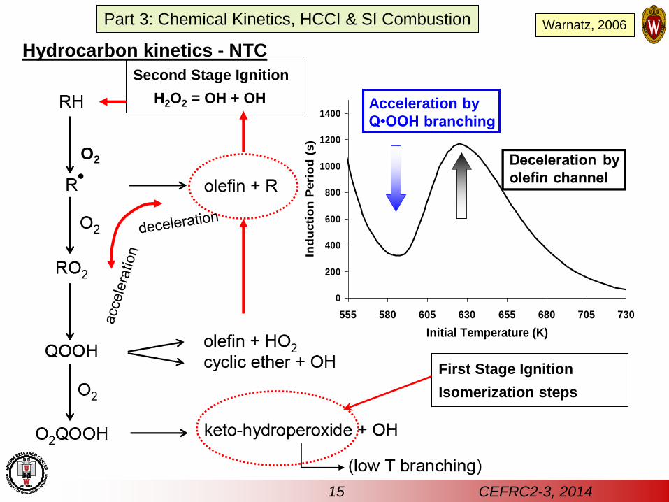
Acceleration by
Q•OOH branching
First Stage Ignition
Isomerization steps
O2
Hydrocarbon kinetics - NTC
Second Stage Ignition
H2O2 = OH + OH
15 CEFRC2-3, 2014
.
Part 3: Chemical Kinetics, HCCI & SI Combustion Warnatz, 2006
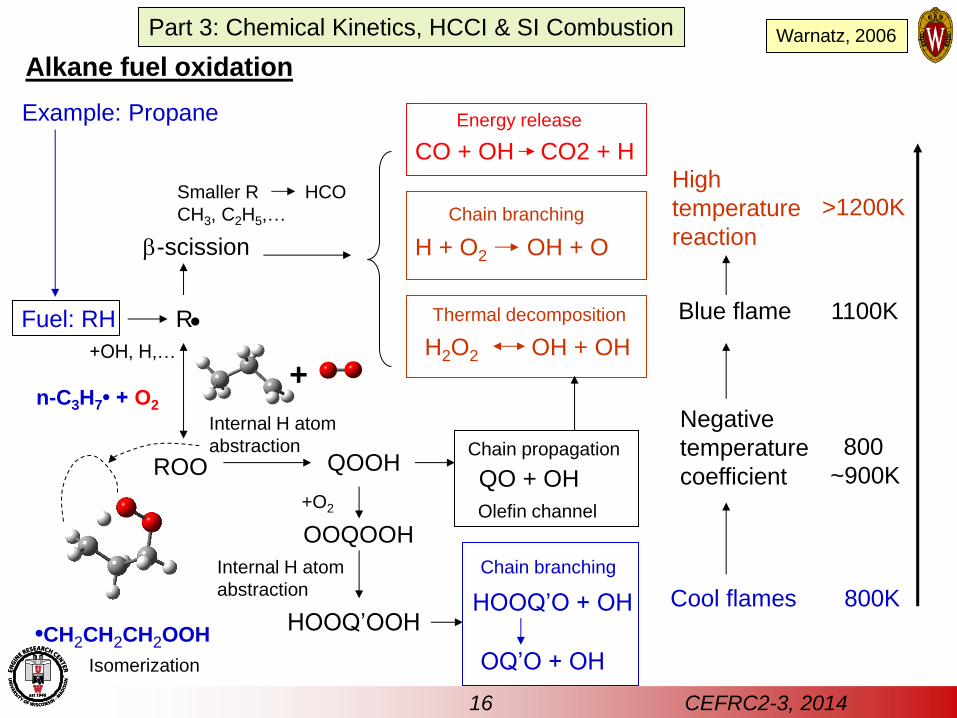
Fuel: RH R
+OH, H,…
ROO QOOH
Internal H atom
abstraction
b-scission
Smaller R
CH3, C2H5,…
Alkane fuel oxidation
HCO
+
•CH2CH2CH2OOH
n-C3H7• + O2
Isomerization
Chain branching
H + O2 OH + O
Thermal decomposition
H2O2 OH + OH
Blue flame
High
temperature
reaction
CO + OH CO2 + H
1100K
>1200K
Energy release
Chain propagation
QO + OH
OOQOOH
+O2
Internal H atom
abstraction
HOOQ’OOH
Chain branching
HOOQ’O + OH
OQ’O + OH
Cool flames
Negative
temperature
coefficient
Olefin channel
800K
800
~900K
Example: Propane
16 CEFRC2-3, 2014
Part 3: Chemical Kinetics, HCCI & SI Combustion Warnatz, 2006
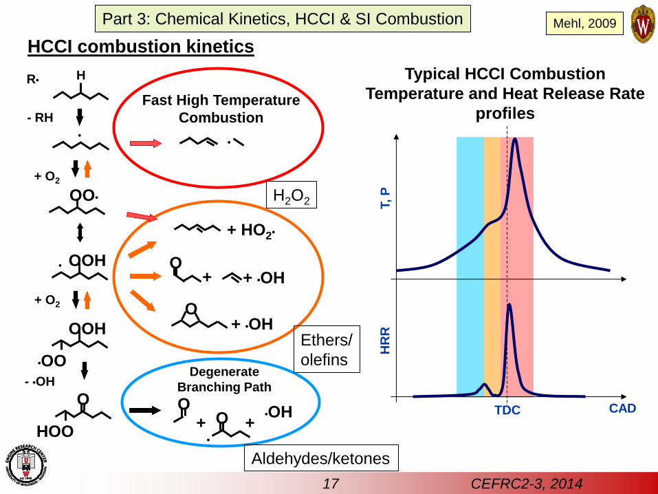
Typical HCCI Combustion
Temperature and Heat Release Rate
profiles
•
R• H
- RH
+ O2
Degenerate
Branching Path
OO•
OOH •
•OO
OOH
HOO
O
+ O2
- •OH
O
O
•
•OH + +
+ HO2•
+ •OH
+ •OH O
+
O
•
Fast High Temperature
Combustion
T, P
CAD
HR
R
TDC
HCCI combustion kinetics
Aldehydes/ketones
Ethers/
olefins
H2O2
Mehl, 2009
17 CEFRC2-3, 2014
Part 3: Chemical Kinetics, HCCI & SI Combustion
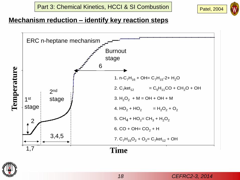
, 7
6
1. n-C7H16 + OH= C7H15-2+ H2O
2. C7ket12 = C5H11CO + CH2O + OH
3. H2O2 + M = OH + OH + M
4. HO2 + HO2 = H2O2 + O2
5. CH4 + HO2= CH3 + H2O2
6. CO + OH= CO2 + H
7. C7H15O2 + O2= C7ket12 + OH
, 7
6
1. n-C7H16 + OH= C7H15-2+ H2O
2. C7ket12 = C5H11CO + CH2O + OH
3. H2O2 + M = OH + OH + M
4. HO2 + HO2 = H2O2 + O2
5. CH4 + HO2= CH3 + H2O2
6. CO + OH= CO2 + H
7. C7H15O2 + O2= C7ket12 + OH
Mechanism reduction – identify key reaction steps
Time
Tem
per
atu
re
Patel, 2004
ERC n-heptane mechanism
18 CEFRC2-3, 2014
3,4,5
6
2
1,7
1st
stage
2nd
stage
Burnout
stage
Part 3: Chemical Kinetics, HCCI & SI Combustion
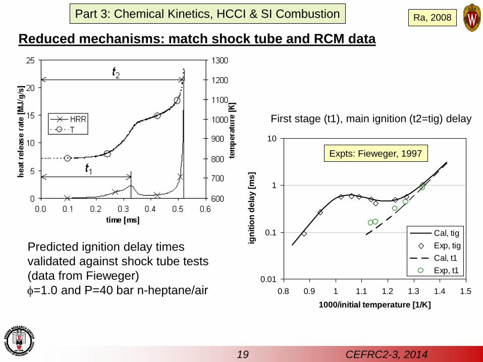
First stage (t1), main ignition (t2=tig) delay
0.01
0.1
1
10
0.8 0.9 1 1.1 1.2 1.3 1.4 1.5
1000/initial temperature [1/K]
ign
itio
n d
ela
y [
ms
]
Cal, tig
Exp, tig
Cal, t1
Exp, t1
Predicted ignition delay times
validated against shock tube tests
(data from Fieweger)
=1.0 and P=40 bar n-heptane/air
Expts: Fieweger, 1997
Reduced mechanisms: match shock tube and RCM data
Ra, 2008
19 CEFRC2-3, 2014
Part 3: Chemical Kinetics, HCCI & SI Combustion
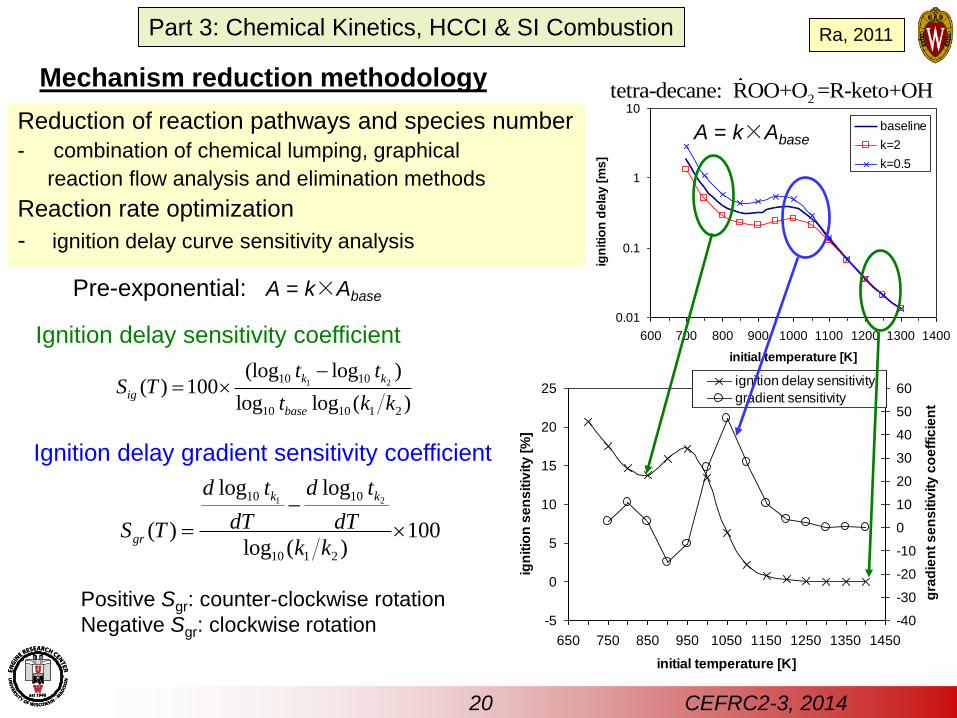
Mechanism reduction methodology
Reduction of reaction pathways and species number
- combination of chemical lumping, graphical
reaction flow analysis and elimination methods
Reaction rate optimization
- ignition delay curve sensitivity analysis
-5
0
5
10
15
20
25
650 750 850 950 1050 1150 1250 1350 1450
initial temperature [K]
ign
itio
n s
en
sit
ivit
y [
%]
-40
-30
-20
-10
0
10
20
30
40
50
60
gra
die
nt
se
ns
itiv
ity
co
eff
icie
nt
ignition delay sensitivity
gradient sensitivity
0.01
0.1
1
10
600 700 800 900 1000 1100 1200 1300 1400
initial temperature [K]
ign
itio
n d
ela
y [
ms
]
baseline
k=2
k=0.5
2tetra-decane: ROO+O =R-keto+OH
1 210 10
10 10 1 2
(log log )( ) 100
log log ( )
k k
ig
base
t tS T
t k k
Ignition delay sensitivity coefficient
1 210 10
10 1 2
log log
( ) 100log ( )
k k
gr
d t d t
dT dTS Tk k
Ignition delay gradient sensitivity coefficient
Positive Sgr: counter-clockwise rotation
Negative Sgr: clockwise rotation
A = k×Abase
A = k×Abase Pre-exponential:
20 CEFRC2-3, 2014
Part 3: Chemical Kinetics, HCCI & SI Combustion Ra, 2011
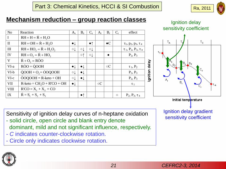
No Reaction As Bs Cs Ar Br Cr effect
I 2RH H R H O
II 2RH OH R H O ●↓ ●↑ ●C τ1, p2, p3, τ 4
III 2 2 2RH HO R H O ○↓ ○↓ ○↓ τ 1, P2, P3, τ 4
IV 2 2RH O R HO ○↑ ○↓ ● P2, P3
V 2R O ROO
VI-a ROO = QOOH ●↓ ●↓ ○C τ 1, P2
VI-b 2QOOH + O = OOQOOH ○↓ ●↓ P2, P3
VI-c OOQOOH = R-keto + OH ○↓ ●↓ P2, P3
VII 2R-keto = CH O + R'CO + OH ●↓ ○C τ 1
VIII 1 2R'CO = X + X + CO
IX 1 2 3R = S + S + S ●↑ ○ P2, P3, τ 4
Sensitivity of ignition delay curves of n-heptane oxidation
- solid circle, open circle and blank entry denote
dominant, mild and not significant influence, respectively.
- C indicates counter-clockwise rotation.
- Circle only indicates clockwise rotation.
Mechanism reduction – group reaction classes Ignition delay
sensitivity coefficient
Ignition delay gradient
sensitivity coefficient
21 CEFRC2-3, 2014
Part 3: Chemical Kinetics, HCCI & SI Combustion Ra, 2011
22 CEFRC2-3, 2014
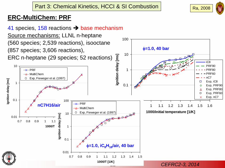
ERC-MultiChem: PRF
41 species, 158 reactions base mechanism
Source mechanisms: LLNL n-heptane
(560 species; 2,539 reactions), isooctane
(857 species; 3,606 reactions),
ERC n-heptane (29 species; 52 reactions)
0.01
0.1
1
10
0.7 0.8 0.9 1 1.1 1.2 1.3 1.4 1.5
1000/T [1/K]
ign
itio
n d
ela
y [
ms]
PRF
MultiChem
Exp, Fieweger et al. (1997)
0.01
0.1
1
10
100
0.8 0.9 1 1.1 1.2 1.3 1.4 1.5 1.6
1000/initial temperature [1/K]
ign
itio
n d
ela
y [
ms]
iC8
PRF90
PRF80
PRF60
nC7
Exp, iC8
Exp, PRF90
Exp, PRF80
Exp, PRF60
Exp, nC7
0.01
0.1
1
10
100
0.7 0.8 0.9 1 1.1 1.2 1.3 1.4 1.5
1000/T [1/K]
ign
itio
n d
ela
y [
ms
]
PRF
MultiChem
Exp, Fieweger et al. (1997)
=1.0, iC8H18/air, 40 bar
=1.0, 40 bar
nC7H16/air
Part 3: Chemical Kinetics, HCCI & SI Combustion Ra, 2008
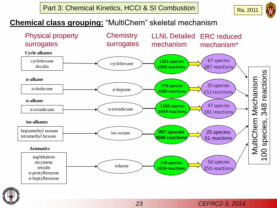
Cyclo alkanes
n-alkane
n-alkane
iso-alkanes
Aromatics
cyclohexane
decalin cyclohexane
n-dodecane
n-heptane
n-octadecane
n-tetradecane
naphthalene
mcymene
tetralin
n-pentylbenzene
n-heptylbenzene
toluene
heptamethyl nonane
tetramethyl hexane
iso-octane
Chemical class grouping: “MultiChem” skeletal mechanism
25 species
51 reactions
857 species
3586 reactions
Physical property
surrogates
Chemistry
surrogates LLNL Detailed
mechanism ERC reduced
mechanism*
Mu
ltiC
he
m M
ech
an
ism
10
0 s
pe
cie
s, 3
48
re
actio
ns
23 CEFRC2-3, 2014
Part 3: Chemical Kinetics, HCCI & SI Combustion Ra, 2011
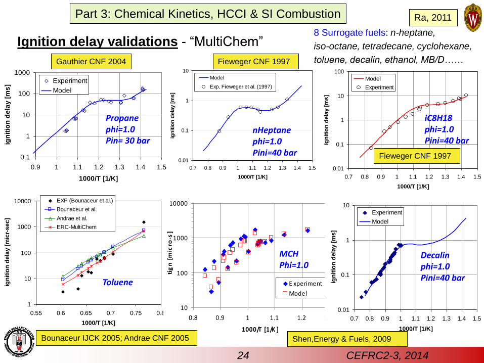
Ignition delay validations - “MultiChem”
0.1
1
10
100
1000
0.9 1 1.1 1.2 1.3 1.4 1.5
1000/T [1/K]
ign
itio
n d
ela
y [
ms
]
Experiment
Model
Propane phi=1.0 Pin= 30 bar
Gauthier CNF 2004
0.01
0.1
1
10
0.7 0.8 0.9 1 1.1 1.2 1.3 1.4 1.5
1000/T [1/K]ig
nit
ion
de
lay
[m
s]
Model
Exp, Fieweger et al. (1997)
nHeptane phi=1.0 Pini=40 bar
1
10
100
1000
10000
0.55 0.6 0.65 0.7 0.75 0.8
1000/T [1/K]
ign
itio
n d
ela
y [
mic
r-s
ec
]
EXP (Bounaceur et al.)
Bounaceur et al.
Andrae et al.
ERC-MultiChem
Toluene
10
100
1000
10000
0.8 0.9 1 1.1 1.2 1.3
1000/T [1/K ]
tig
n [
mic
ro-s
]
E xperiment
Model
MCH Phi=1.0
0.01
0.1
1
10
0.7 0.8 0.9 1 1.1 1.2 1.3 1.4 1.5
1000/T [1/K]ig
nit
ion
de
lay
[m
s]
Experiment
Model
Decalin phi=1.0 Pini=40 bar
0.01
0.1
1
10
100
0.7 0.8 0.9 1 1.1 1.2 1.3 1.4 1.5
1000/T [1/K]
ign
itio
n d
ela
y [
ms
]
Model
Experiment
iC8H18 phi=1.0 Pini=40 bar
Fieweger CNF 1997
Shen,Energy & Fuels, 2009 Bounaceur IJCK 2005; Andrae CNF 2005
Fieweger CNF 1997
8 Surrogate fuels: n-heptane,
iso-octane, tetradecane, cyclohexane,
toluene, decalin, ethanol, MB/D……
24 CEFRC2-3, 2014
Part 3: Chemical Kinetics, HCCI & SI Combustion Ra, 2011
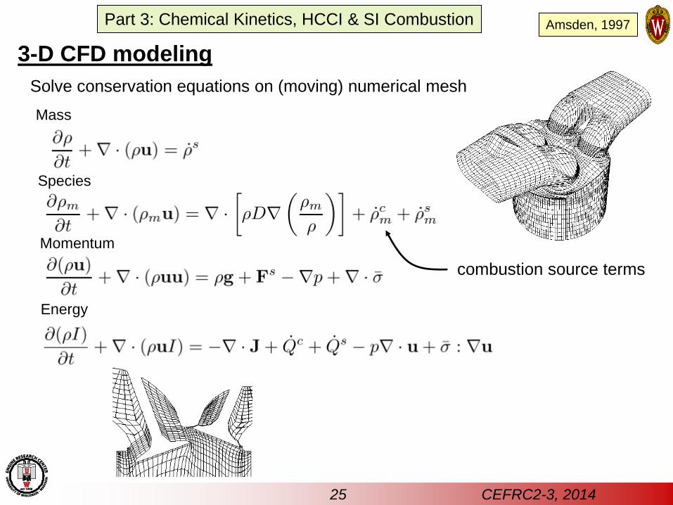
3-D CFD modeling
Solve conservation equations on (moving) numerical mesh
Mass
Species
Momentum
Energy
combustion source terms
Amsden, 1997
25 CEFRC2-3, 2014
Part 3: Chemical Kinetics, HCCI & SI Combustion
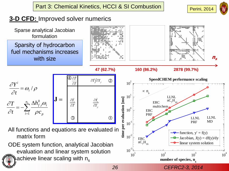
Sparse analytical Jacobian
formulation
All functions and equations are evaluated in
matrix form
ODE system function, analytical Jacobian
evaluation and linear system solution
achieve linear scaling with ns
non-zeroes: 860; sparsity: 62.7%
ERC PRF mechanism Jacobian structure LLNL n-heptane mech. Jacobian structure
non-zeroes: 3571; sparsity: 86.2% non-zeroes = 49763; sparsity: 99.7%
LLNL MD mechanism Jacobian structure
ns
47 (62.7%) 160 (86.2%) 2878 (99.7%)
101
102
103
104
10-3
10-2
10-1
100
101
102
number of species, ns
tim
e p
er e
va
lua
tio
n [
ms]
SpeedCHEM performance scaling
function, y' = f(y)
Jacobian, J(y) = df(y)/dy
linear system solution
LLNLMD
LLNLPRF
ns
ERCPRF
ERCnC
7H
16
LLNLnC
7H
16ERCmultichem
Sparsity of hydrocarbon fuel mechanisms increases
with size
0
,
1
snf i i
i p
hT
t c
/i
i
Y
t
26 CEFRC2-3, 2014
Perini, 2014
3-D CFD: Improved solver numerics
Part 3: Chemical Kinetics, HCCI & SI Combustion
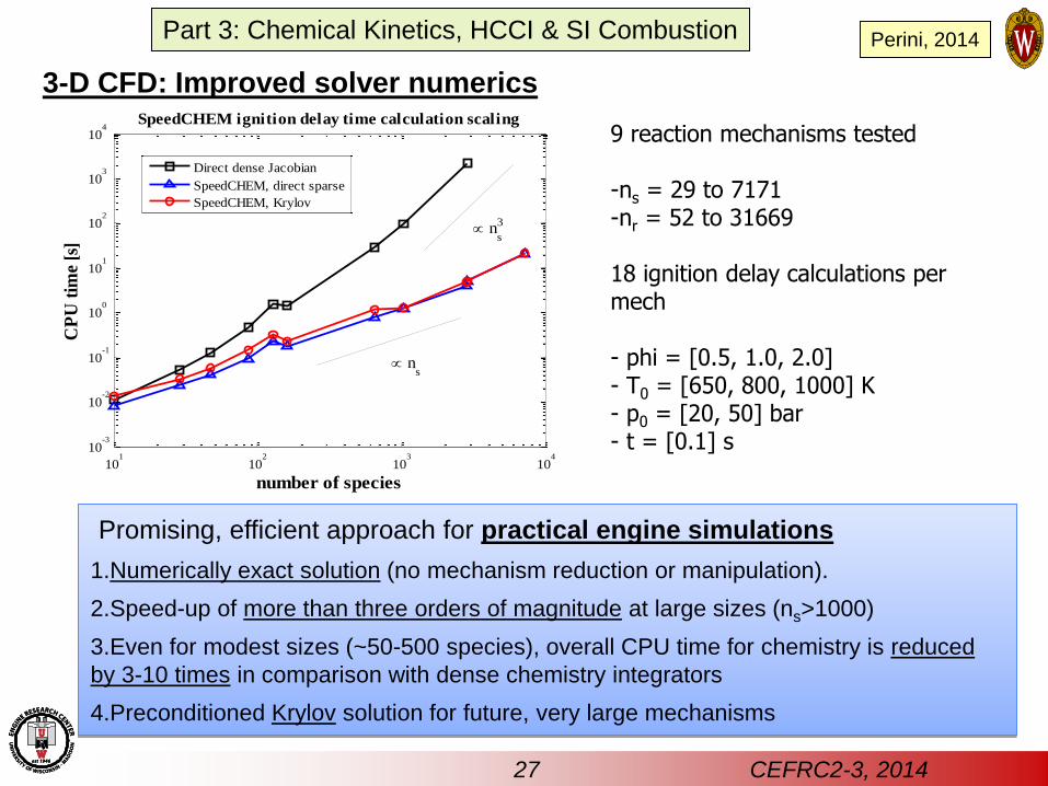
Promising, efficient approach for practical engine simulations
1.Numerically exact solution (no mechanism reduction or manipulation).
2.Speed-up of more than three orders of magnitude at large sizes (ns>1000)
3.Even for modest sizes (~50-500 species), overall CPU time for chemistry is reduced
by 3-10 times in comparison with dense chemistry integrators
4.Preconditioned Krylov solution for future, very large mechanisms
9 reaction mechanisms tested -ns = 29 to 7171 -nr = 52 to 31669 18 ignition delay calculations per mech - phi = [0.5, 1.0, 2.0] - T0 = [650, 800, 1000] K - p0 = [20, 50] bar - t = [0.1] s
101
102
103
104
10-3
10-2
10-1
100
101
102
103
104
number of species
CP
U t
ime
[s]
SpeedCHEM ignition delay time calculation scaling
Direct dense Jacobian
SpeedCHEM, direct sparse
SpeedCHEM, Krylov
ns
ns
3
Perini, 2014
27 CEFRC2-3, 2014
3-D CFD: Improved solver numerics
Part 3: Chemical Kinetics, HCCI & SI Combustion
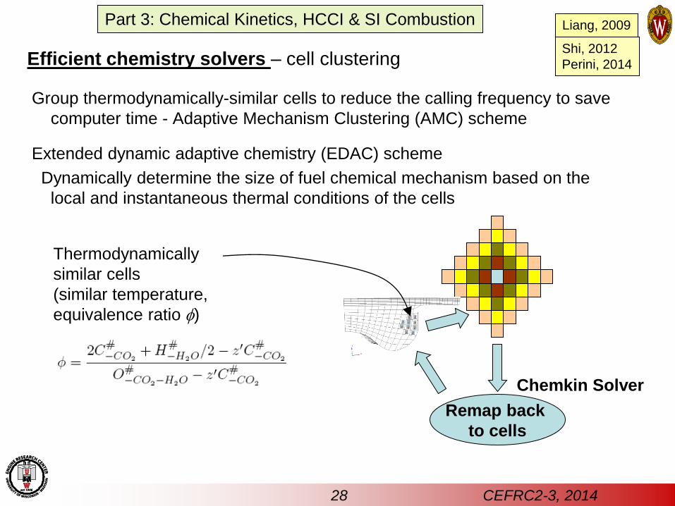
Group thermodynamically-similar cells to reduce the calling frequency to save
computer time - Adaptive Mechanism Clustering (AMC) scheme
Extended dynamic adaptive chemistry (EDAC) scheme
Dynamically determine the size of fuel chemical mechanism based on the
local and instantaneous thermal conditions of the cells
Shi, 2012
Perini, 2014 Efficient chemistry solvers – cell clustering
Chemkin Solver
Remap back
to cells
Thermodynamically
similar cells
(similar temperature,
equivalence ratio )
Liang, 2009
28 CEFRC2-3, 2014
Part 3: Chemical Kinetics, HCCI & SI Combustion
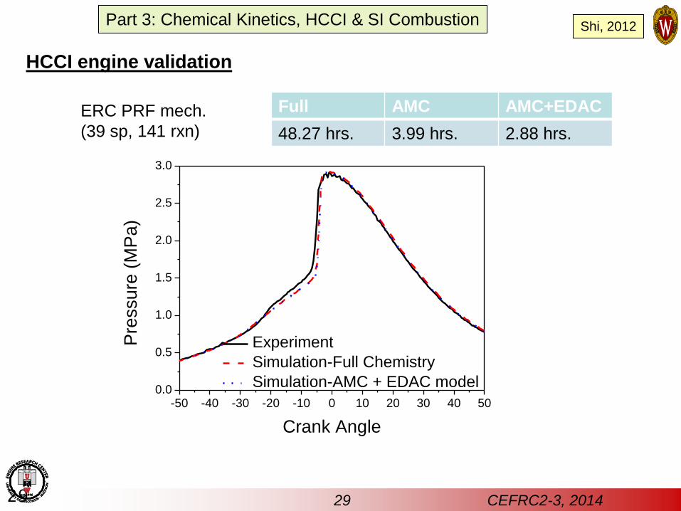
-50 -40 -30 -20 -10 0 10 20 30 40 500.0
0.5
1.0
1.5
2.0
2.5
3.0
Pre
ssure
(M
Pa)
Crank Angle
Experiment
Simulation-Full Chemistry
Simulation-AMC + EDAC model
ERC PRF mech.
(39 sp, 141 rxn)
Full AMC AMC+EDAC
48.27 hrs. 3.99 hrs. 2.88 hrs.
29
HCCI engine validation
Shi, 2012
29 CEFRC2-3, 2014
Part 3: Chemical Kinetics, HCCI & SI Combustion
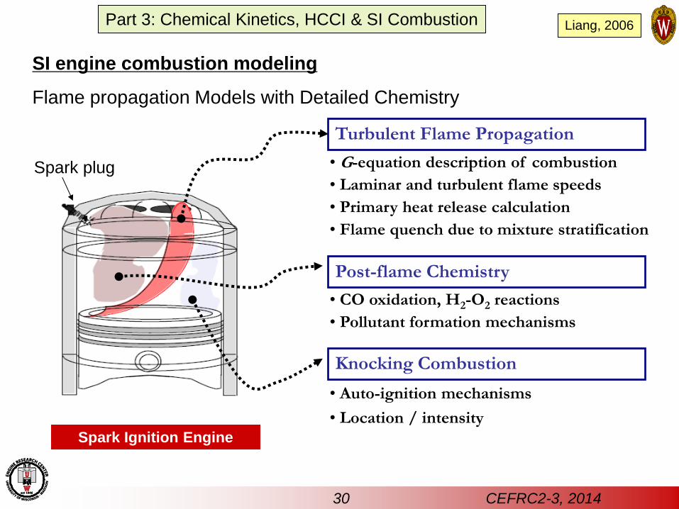
Spark Ignition Engine
Turbulent Flame Propagation
• G-equation description of combustion
• Laminar and turbulent flame speeds
• Primary heat release calculation
• Flame quench due to mixture stratification
Post-flame Chemistry
• CO oxidation, H2-O2 reactions
• Pollutant formation mechanisms
Knocking Combustion
• Auto-ignition mechanisms
• Location / intensity
SI engine combustion modeling
Flame propagation Models with Detailed Chemistry
Liang, 2006
30 CEFRC2-3, 2014
Spark plug
Part 3: Chemical Kinetics, HCCI & SI Combustion
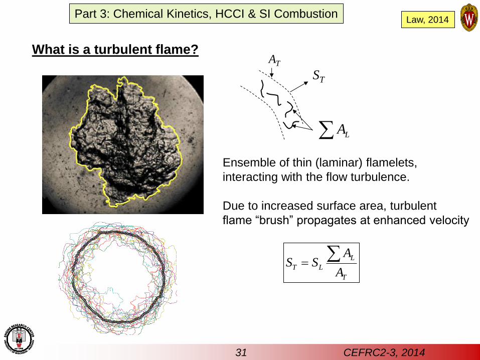
What is a turbulent flame?
Law, 2014
ST
Ensemble of thin (laminar) flamelets,
interacting with the flow turbulence.
Due to increased surface area, turbulent
flame “brush” propagates at enhanced velocity
L
T L
T
AS S
A
AT
LA
31 CEFRC2-3, 2014
Part 3: Chemical Kinetics, HCCI & SI Combustion
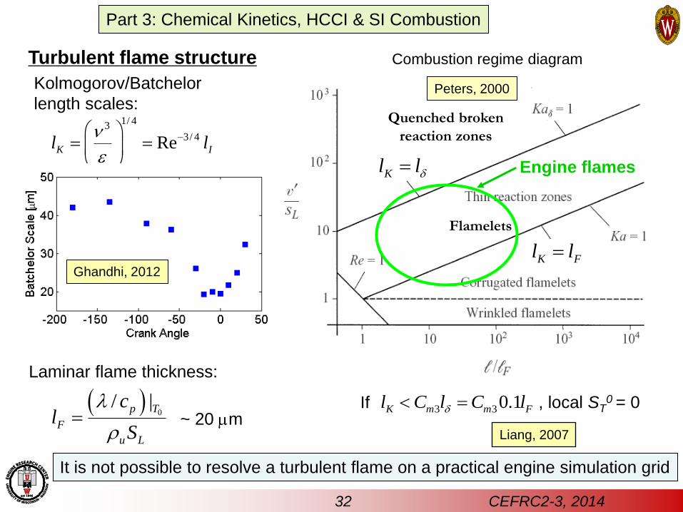
, local ST0 = 0
Quenched broken
reaction zones
Kl l
K Fl l
3 30.1K m m Fl C l C l
Combustion regime diagram
If
Flamelets
Turbulent flame structure
1/ 43
3/ 4ReK Il l
e
0
/ |p T
F
u L
cl
S
Kolmogorov/Batchelor
length scales:
Laminar flame thickness:
Ghandhi, 2012
~ 20 mm
It is not possible to resolve a turbulent flame on a practical engine simulation grid
Peters, 2000
Liang, 2007
32 CEFRC2-3, 2014
Engine flames
Part 3: Chemical Kinetics, HCCI & SI Combustion
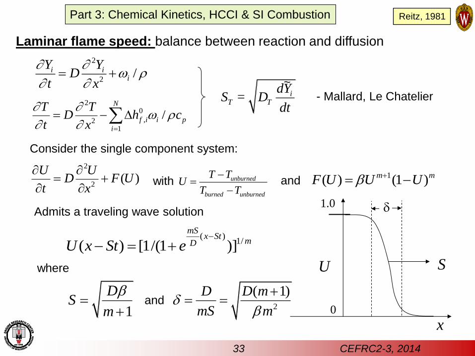
Laminar flame speed: balance between reaction and diffusion
iT T
dYS = D
dt
33 CEFRC2-3, 2014
2
2/i i
i
Y YD
t x
20
,21
/N
f i i p
i
T TD h c
t x
( )1/( ) [1/(1 )]
mSx St
mDU x St e
2
2( )
U UD F U
t x
1( ) (1 )m mF U U Ub
1
DS
m
b
Consider the single component system:
unburned
burned unburned
T TU
T T
with and
Admits a traveling wave solution
where
2
( 1)D D m
mS m
b
and
U
x
S
1.0
0
- Mallard, Le Chatelier
~
Part 3: Chemical Kinetics, HCCI & SI Combustion Reitz, 1981
34 CEFRC2-3, 2014
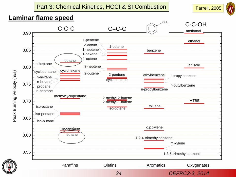
Laminar flame speed
0.90
0.85
0.80
0.75
0.70
0.65
0.60
0.55
Pe
ak B
urn
ing
Ve
locity (
m/s
)
Paraffins Olefins Aromatics
toluene
o,p xylene
Oxygenates
cyclohexane
benzene
anisole
ethanol
MTBE
methylcyclopentane
1,2,4-trimethylbenzene
iso-octene
n-butane
propane
ethane
methane
n-pentane
iso-octane
iso-pentane
iso-butane
n-hexane
t-butylbenzene
i-propylbenzene
m-xylene
ethylbenzene
n-propylbenzene
1-butene
2-pentene
1-hexene
2-butene
3-heptene
cyclopentene
2-methyl-2-butene2-methyl-1-butene
propene
1,3,5-trimethylbenzene
1-pentene
cyclopentane
n-heptane
1-heptene
1-octene
neopentane
C-C-C C=C-C C-C-OH methanol
Part 3: Chemical Kinetics, HCCI & SI Combustion Farrell, 2005
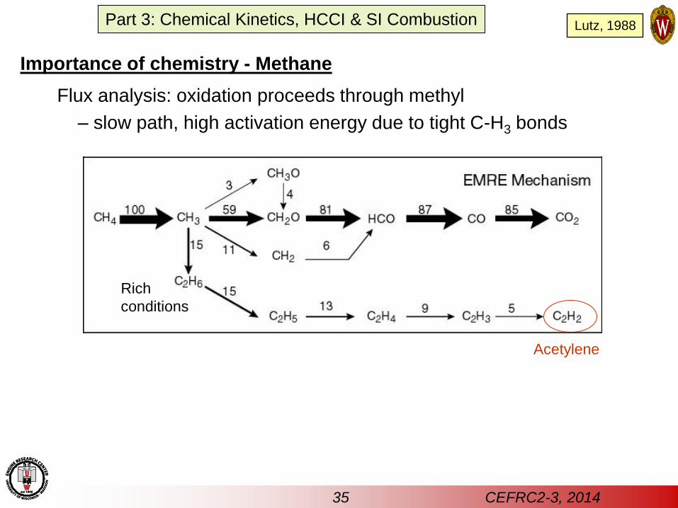
Importance of chemistry - Methane
Flux analysis: oxidation proceeds through methyl
– slow path, high activation energy due to tight C-H3 bonds
Acetylene
Rich
conditions
35 CEFRC2-3, 2014
Part 3: Chemical Kinetics, HCCI & SI Combustion Lutz, 1988
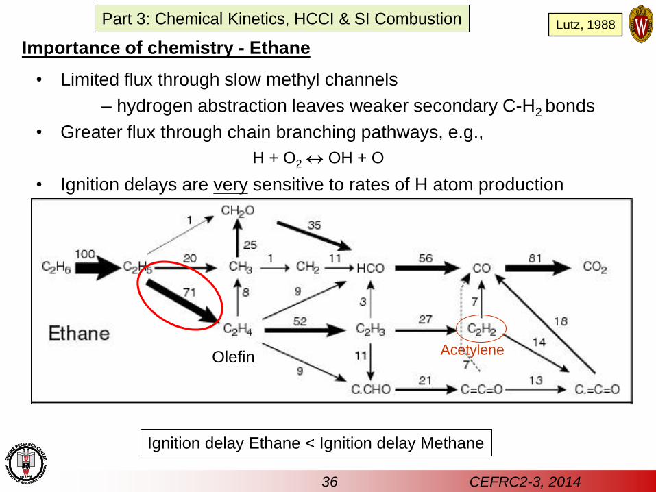
• Limited flux through slow methyl channels
– hydrogen abstraction leaves weaker secondary C-H2 bonds
• Greater flux through chain branching pathways, e.g.,
• Ignition delays are very sensitive to rates of H atom production
H + O2 OH + O
Ignition delay Ethane < Ignition delay Methane
Olefin Acetylene
36 CEFRC2-3, 2014
Importance of chemistry - Ethane
Part 3: Chemical Kinetics, HCCI & SI Combustion Lutz, 1988
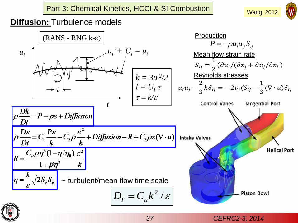
Diffusion: Turbulence models
ijji SuuP (RANS - RNG k-e
Wang, 2012
t
ui ui’ + Ui = ui
t l = Ui t k = 3ui
2/2
t k/e
~ turbulent/mean flow time scale
Production
Mean flow strain rate
Reynolds stresses
37 CEFRC2-3, 2014
2 /TD C km e
Part 3: Chemical Kinetics, HCCI & SI Combustion
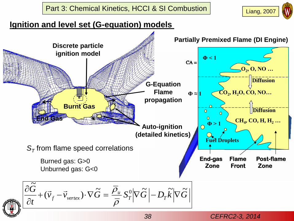
End Gas
Auto-ignition
(detailed kinetics)
G-Equation
Flame
propagation Burnt Gas
Discrete particle
ignition model
ST from flame speed correlations
GkDGSGvvt
GTT
uvertexf
~~~~)(
~0
Ignition and level set (G-equation) models
Burned gas: G>0
Unburned gas: G<0
Partially Premixed Flame (DI Engine)
Liang, 2007
38 CEFRC2-3, 2014
Part 3: Chemical Kinetics, HCCI & SI Combustion
Φ ≈ 1
Φ > 1
Φ < 1
CO2, H2O, CO, NO…
O2, O, NO …
Fuel Droplets
Diffusion
Diffusion
End-gas Flame Post-flame
Zone Front Zone
CH4, CO, H, H2 …
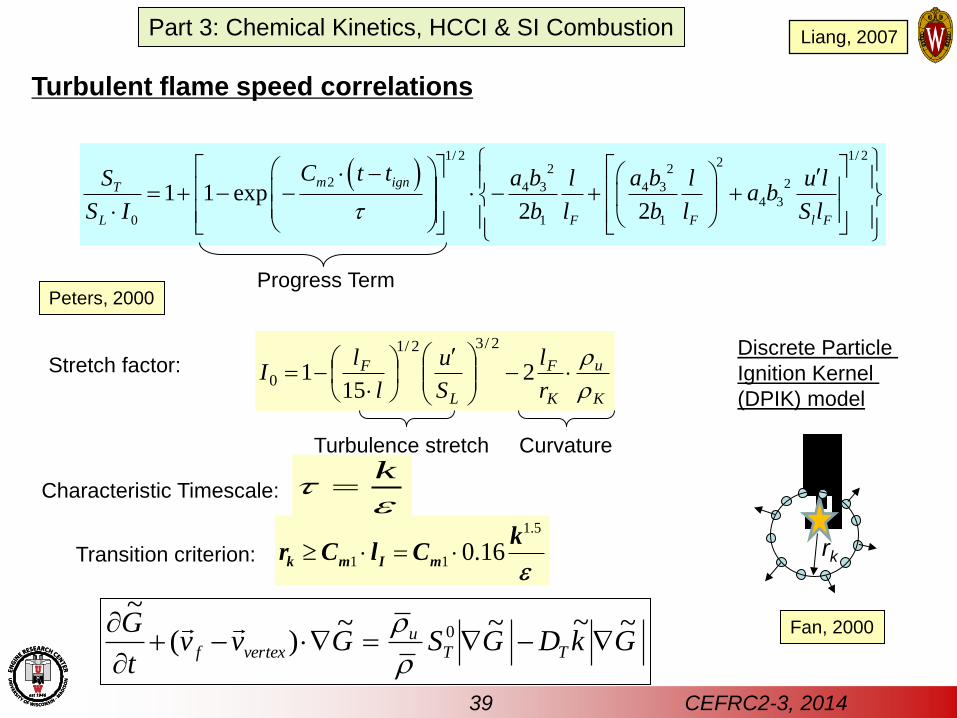
Turbulent flame speed correlations
1/ 2 1/ 2
22 2
2 24 3 4 34 3
0 1 1
1 1 exp2 2
m ignT
L F F l F
C t t a b a bS l l u la b
S I b l b l S lt
Progress Term
1.5
1 1 0.16 k m I m
kr C l C
e
et
k
K
u
K
F
L
F
r
l
S
u
l
lI
2
151
2/32/1
0
Transition criterion:
Characteristic Timescale:
Stretch factor:
Turbulence stretch Curvature
Discrete Particle
Ignition Kernel
(DPIK) model
rk
Fan, 2000 GkDGSGvv
t
GTT
uvertexf
~~~~)(
~0
Peters, 2000
39 CEFRC2-3, 2014
Part 3: Chemical Kinetics, HCCI & SI Combustion Liang, 2007
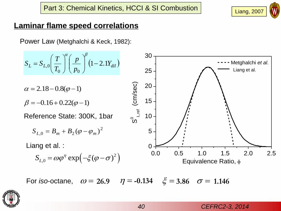
Laminar flame speed correlations
Power Law (Metghalchi & Keck, 1982):
dilLL Yp
p
T
TSS 1.21
00
0,
b
)1(8.018.2
)1(22.016.0 b
Liang et al. :
Reference State: 300K, 1bar
220, )( mmL BBS
0.0 0.5 1.0 1.5 2.0 2.50
5
10
15
20
25
30
Equivalence Ratio,
S0
L,r
ef
(cm
/se
c)
Metghalchi et al.
Present study
For iso-octane,
2
,0 exp ( )LS
26.9 -0.134 3.86 1.146
Liang et al.
Liang, 2007
40 CEFRC2-3, 2014
Part 3: Chemical Kinetics, HCCI & SI Combustion
41 CEFRC2-3, 2014
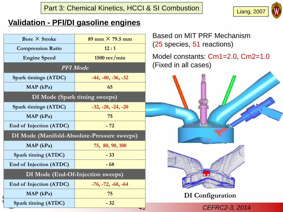
Validation - PFI/DI gasoline engines
Bore × Stroke 89 mm × 79.5 mm
Compression Ratio 12 : 1
Engine Speed 1500 rev/min
PFI Mode
Spark timings (ATDC) -44, -40, -36, -32
MAP (kPa) 65
DI Mode (Spark timing sweeps)
Spark timings (ATDC) -32, -28, -24, -20
MAP (kPa) 75
End of Injection (ATDC) - 72
DI Mode (Manifold-Absolute-Pressure sweeps)
MAP (kPa) 75, 80, 90, 100
Spark timing (ATDC) - 33
End of Injection (ATDC) - 68
DI Mode (End-Of-Injection sweeps)
End of Injection (ATDC) -76, -72, -68, -64
MAP (kPa) 75
Spark timing (ATDC) - 32
Based on MIT PRF Mechanism
(25 species, 51 reactions)
Model constants: Cm1=2.0, Cm2=1.0
(Fixed in all cases)
DI Configuration
Part 3: Chemical Kinetics, HCCI & SI Combustion Liang, 2007
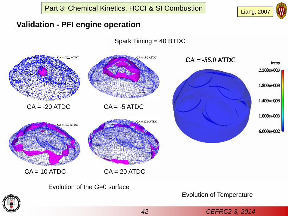
Validation - PFI engine operation
Spark Timing = 40 BTDC
Evolution of the G=0 surface
CA = -20 ATDC CA = -5 ATDC
CA = 10 ATDC CA = 20 ATDC
Evolution of Temperature
42 CEFRC2-3, 2014
Part 3: Chemical Kinetics, HCCI & SI Combustion Liang, 2007
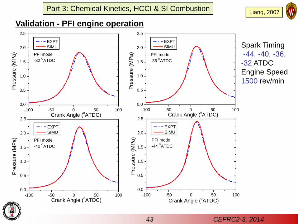
Validation - PFI engine operation
Spark Timing
-44, -40, -36,
-32 ATDC
Engine Speed
1500 rev/min
-100 -50 0 50 100
0.0
0.5
1.0
1.5
2.0
2.5
PFI mode
-32 OATDC
Pre
ssu
re (
MP
a)
Crank Angle (oATDC)
EXPT
SIMU
-100 -50 0 50 100
0.0
0.5
1.0
1.5
2.0
2.5
PFI mode
-36 OATDC
Pre
ssu
re (
MP
a)
Crank Angle (oATDC)
EXPT
SIMU
-100 -50 0 50 100
0.0
0.5
1.0
1.5
2.0
2.5
PFI mode
-40 OATDC
Pre
ssu
re (
MP
a)
Crank Angle (oATDC)
EXPT
SIMU
-100 -50 0 50 100
0.0
0.5
1.0
1.5
2.0
2.5
Pre
ssu
re (
MP
a)
Crank Angle (oATDC)
EXPT
SIMU
PFI mode
-44 OATDC
43 CEFRC2-3, 2014
Part 3: Chemical Kinetics, HCCI & SI Combustion Liang, 2007
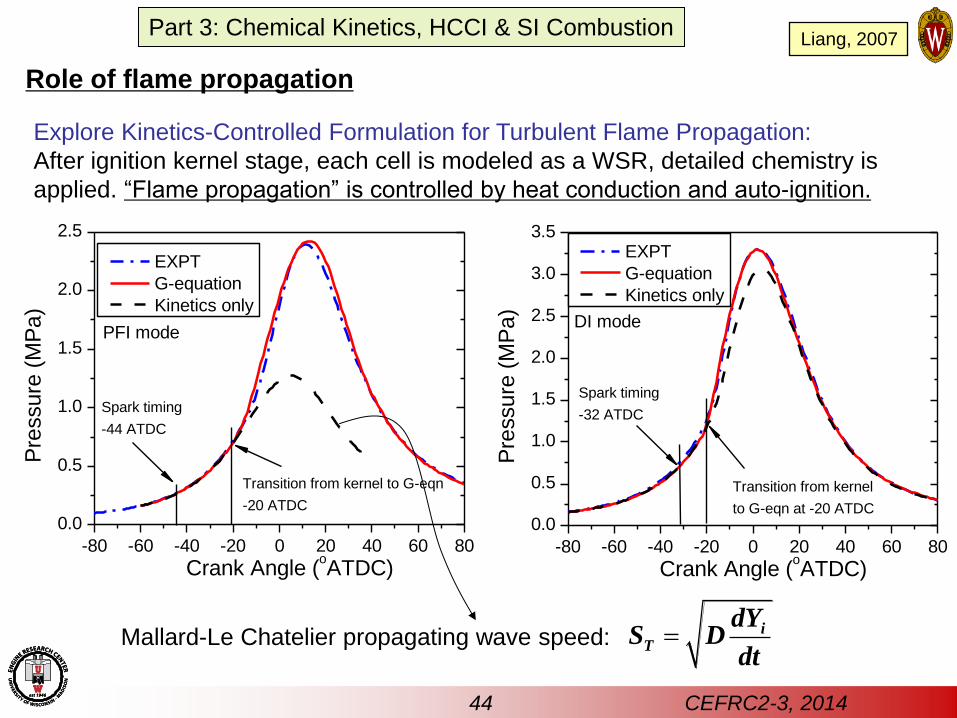
Role of flame propagation
Explore Kinetics-Controlled Formulation for Turbulent Flame Propagation:
After ignition kernel stage, each cell is modeled as a WSR, detailed chemistry is
applied. “Flame propagation” is controlled by heat conduction and auto-ignition.
-80 -60 -40 -20 0 20 40 60 80
0.0
0.5
1.0
1.5
2.0
2.5
Transition from kernel to G-eqn
-20 ATDC
Pre
ssure
(M
Pa)
Crank Angle (oATDC)
EXPT
G-equation
Kinetics only
Spark timing
-44 ATDC
PFI mode
-80 -60 -40 -20 0 20 40 60 80
0.0
0.5
1.0
1.5
2.0
2.5
3.0
3.5
Transition from kernel
to G-eqn at -20 ATDC
DI mode
Spark timing
-32 ATDC
Pre
ssure
(M
Pa)
Crank Angle (oATDC)
EXPT
G-equation
Kinetics only
Mallard-Le Chatelier propagating wave speed: iT
dYS D
dt
44 CEFRC2-3, 2014
Part 3: Chemical Kinetics, HCCI & SI Combustion Liang, 2007
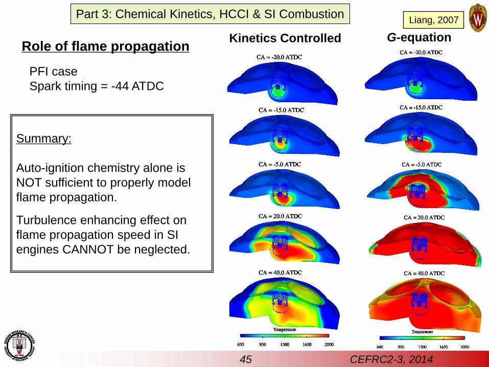
Kinetics Controlled G-equation
Summary:
Auto-ignition chemistry alone is
NOT sufficient to properly model
flame propagation.
Turbulence enhancing effect on
flame propagation speed in SI
engines CANNOT be neglected.
PFI case
Spark timing = -44 ATDC
Role of flame propagation
45 CEFRC2-3, 2014
Part 3: Chemical Kinetics, HCCI & SI Combustion Liang, 2007