Embed Size (px)
Citation preview
Real-time Rendering of Burning Solid Objects in Video Games
Dhanyu Amarasinghe and Ian Parberry
Technical Report LARC-2012-01
Laboratory for Recreational Computing Department of Computer Science & Engineering
University of North Texas Denton, Texas, USA
May, 2012

Real-time Rendering of Burning
Solid Objects in Video Games
Dhanyu Amarasinghe
Dept. of Computer Science & Engineering
University of North Texas
Ian Parberry
Dept. of Computer Science & Engineering
University of North Texas
Abstract
Objects in 3D games are typically shell models, apolygon mesh representing the shell or skin of theobject. While emulation of the behaviour of shellmodels under combustion is sufficient for manygame applications and is fairly well studied, solidobjects do in fact burn rather differently than shellobjects. We show how to manipulate shell modelsso that they appear to burn as solid models. Sinceour burning objects will be only a small part of avideo game, computation speed is of the essence.We demonstrate that our method uses only a frac-tion of the computational power available by imple-menting the computation on a modest GPU usingCUDA.
Keywords Hardware acceleration, volume ren-dering, freeform deformation, procedural genera-tion, polygonal modeling, CUDA, refinement, sub-division.
General Terms Video games, visualization, al-gorithms, performance, design and modeling.
1. Introduction
Many cutting edge console and PC games competeto attract seasoned players by increasing realismover and above what they are accustomed to inother games. Replicating the details of a physicalprocess such as fire can readily draw the player intowilling suspension of disbelief.
The typical object in a 3D video game is rep-resented by a polygonal mesh in the shape of itssurface, which we will call a shell model. The prob-lem of applying shape changes to a shell modelby emulating solid object properties without over-loading the available computational resources is a
Figure 1: Shell model deformation (left) vs solid modeldeformation (right).
challenging one. We propose to tackle the emula-tion of solid object deformation and consumptionunder combustion. Solid objects are expected toburn much differently than shells. Aside from theobvious difference of being able to see the inside ofa burned-out shell (Figure 1, left), a solid objectwill melt and deform under heat in a different way(Figure 1, right).
The structure of the remainder of this paper is asfollows. In Section 2 we describe some prior work.In Section 3 we describe our representation frame-work for the internal deformation and the key fea-tures of such a strategy. Section 4 describes ourapproach to implementing the structural deforma-tion framework. Section 5 contains a few notes onour optimization techniques and results. Section 6contains the conclusion and further work.
2. Previous Work
This paper extends our previous work on the emu-lation of burning objects in video games. Amaras-inghe and Parberry [2] laid down the foundation of
1

Figure 2: The combustion of a solid model and the spread of procedural fire.
our approach and demonstrated the ability to real-istically burn in real time on a relatively slow GPUa high-polygon count shell model of a toy satellite.Amarasinghe and Parberry [1] extended this workto models with a very low polygon count by judi-cious use of procedural triangulation in the areasthat are on fire, and demonstrated the ability torealistically burn on the same GPU a 12-triangleshell model of a door. This approach also lent itselfeasily to dynamic Level of Detail rendering.
Model deformation is a popular topic in theComputer Graphics community. We single out thefollowing papers as relevant and significant, butwithout exception they strive for realism at thecost of performance. Although they are more re-alistic than our approach, their methods are notreal-time and are therefore more useful for offlineapplications such as motion pictures than for videogames. Melek and Keyser [3, 4] discuss techniquesthat were used in selected object deformation dueto fire. Demetri Terzopoulost and John Platt [11]introduce the theory of elasticity to describe de-formable materials such as rubber, cloth, paper,and flexible metals. Sederberg and Parry [8] in-troduce a technique for deforming solid geometricmodels in a free-form manner. E. B. Tadmor andRob Phillips [10] and Nealen et al. [5] use finiteelement methods to deform complex geometries.Toivanen [9] discusses free deformation of meshes.
Finally, Nguyen Rasmussen and Fedkiwr [6, 7]introduce high quality flame simulations that weuse in our experiments, but they do not addressobject deformation.
3. Internal Deformation
According to Melek and Keyser [3], when an objectburns there are assorted interior chemical reactions
at various stages that lead its properties to changein a process called pyrolysis. Volumetric expansionof heated material is caused by weakening bondsat the molecular level. Internal forces are disturbedby the effect of heat on unstable bond structure,ultimately leading to the consumption of material.This causes changes in the shape of the object’saffected areas. We begin by creating a simplifiedmodel of heat spread.
3.1 The Heat Boundary
The temperature of a burning object changes overboth time and space. The increase in temperaturegenerated by fire changes the mechanical behaviorof the object. Significant thermal response occursdue to the thermal conductivity of the material.Absence of thermal equilibrium of the heat fluxgenerates a heat boundary. As in Amarasinghe andParberry [2], we approximate the expansion of theheat boundary by calculating it around a fixedsolitary point using the following function:
R2 = | sin(πΘ/∆r) + sin(πΘ) +
ψ((x− x0)2 + (y − y0)2 + (z − z0)2)|,
where R = r + ∆r indicates that the radius ris incremented by ∆r in each ∆t time period.The angle Θ is a random value in order to makethe expanding heat boundary irregular in shape.The location of the heat source is (x0, y0, z0). Aswe discussed earlier in [2], the heat index can beapproximated by a constant that depends on thesize of the coarse triangles of the model.
In this paper we address the combustion of solidmodels with an arbitrary number of polygons. Ifthe targeted triangle is considerably larger thanthe rest of the triangles, we can always applythe subdivision techniques from Amarasinghe and
2

Parberry [1]. Thus, the designer can maintain afixed heat index value that is suitable for the modeland maintain the subdivision level accordingly.
The above boundary function creates a roughlyspherical but irregular heat boundary around theheat source. In the real world, heat sources re-produce throughout the burning object as flamesdistribute over time. Figure 3 illustrates the sim-ilarity of the approximated heat boundary expan-sion for single versus multiple heat sources. Themultiple source heat boundary expands through-out the model with behavior similar to our singleheat source approximation implemented using theabove function. Because determination of the au-thentic heat boundary expansion is computation-ally expensive, we believe that the use of a singlesource heat boundary expansion is a viable alter-native for use in video games.
Figure 3: Heat boundary for single vs. multiple heat sourceswith different levels of boundary.
As shown in Figure 3, we divide the heat bound-ary into four different areas. The Virtual HeatBoundary is spread through the model prior tothe actual heat boundary expansion and is used toamortize essential calculations that could apply tothe qualified triangles before the deformation pro-cess begins. The other three boundaries are thoseintroduced in Amarasinghe and Parberry [2]; theInitial Heat Boundary in which combustion is ac-
tively taking place and vertices are preparing to bedeformed, the Combustion Ready Boundary whereignition starts, and the Deform Boundary consist-ing of material that has been burned.
3.2 The Deformation Process
Surface removal as practiced in our prior paperAmarasinghe and Parberry [2] is less useful insolid models than in shell models because the con-sumption of material in a solid model simply re-veals more material just underneath it. Conse-quently solid models have more triangles to de-form than shell models, and these need to be man-aged efficiently and effectively. In order to achievethis we categorize model triangles into three ma-jor types as shown in Figure 4. Those are calledBoundary Qualified Triangles, Combustion Qual-ified Triangles, and Deforming Triangles. Bound-ary Qualified Triangles are the triangles locatedinside the Virtual Heat Boundary. These can becompletely or partially contained within the heatboundary, depending on the size of the triangle.If the latter is the case, triangle subdivision musttake place.Combustion Qualified Triangles are theones that are ready to take part in the first roundof deformation.
Figure 4: categorized Model Triangles
3.3 Inward Contraction Displacement
In shell models the heat-induced deformation ofan object is achieved by displacement of the ver-tices of the model mesh (see Amarasinghe and Par-
3
berry [2]), where the position of each vertex de-pends on given properties such as vertex distance,gravitational force, and material index, and the in-ternal forces work on the triangle pointing towardsthe direction of its vertices. However, when themodel represents a solid object we must also ap-ply inward contraction forces to the vertices.
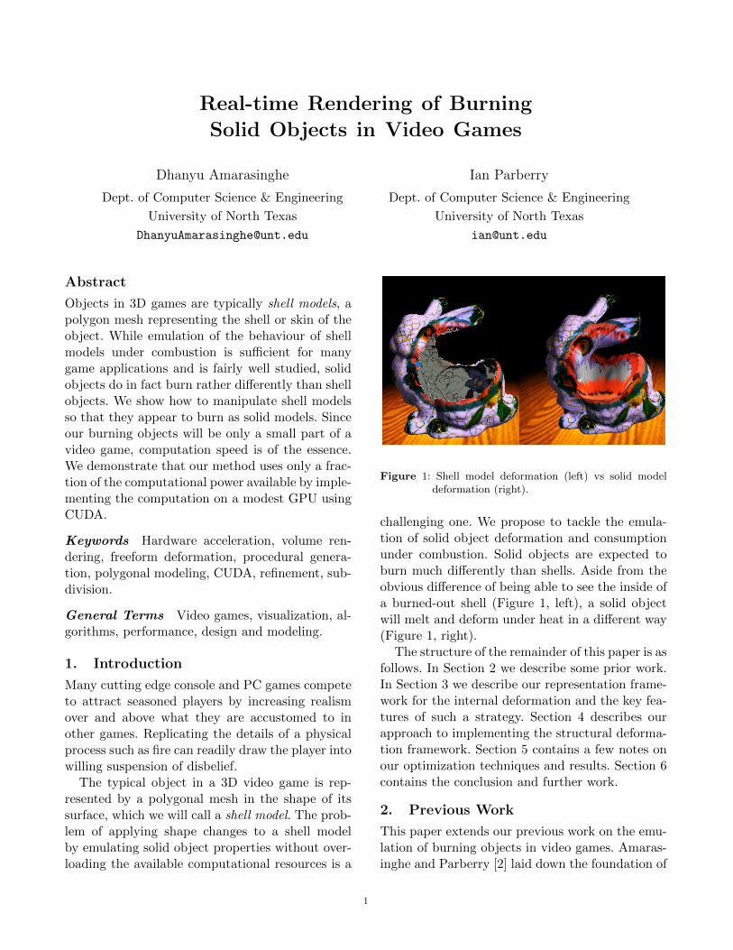
In burning objects, the extending heat wavesweaken the bond strength between adjacent mol-ecules. This weakening effect falls off as a func-tion of the distance from the heat source. As a re-sult, surface molecules move towards the strongerbonds in order to find stable equilibrium betweenthe acting forces. This results in contraction of theburning area of the object. Melek and Keyser [3]also noted that due to multiple internal chemicalreactions at various stages of the combustion pro-cess, material may change state from solid to liq-uid and from liquid to gas. Both these cause re-duction of the mass in affected areas of the burn-ing object. In most cases this will cause an inwardconcave shape in the consumed area. To illustratethis phenomenon in a simulation we have appliedwhat we call the Inward Contraction DisplacementTechnique to calculate the inward movement of thevertices of the Deforming Triangle. The idea of thistechnique is to identify for each triangle a virtualpoint covered by the affected polygonal boundaryin distance (see Figure 5) and use this to calculatethe the local inward displacement.
First we must identify the inward direction ofthe Combustion Qualified Triangle or the Deform-ing Triangle. Secondly, the distance of the virtualpoint must be proportional to the size of the qual-ified triangle. However, calculating random virtualpoints to meet the necessary requirements on con-tinuously deforming polygons is not an efficient so-lution. Therefore, our best approach to succeed thistask is to employ the face normal of the objectand calculate the inverse directional coordinates.To maintain the proportional distance between thevirtual point and the triangle surface, we factor thenormal vector coordinate by the length of eitherside of the triangle (d1 or d2 in Figure 5). That is,
(Xin, Yin, Zin) = −D · (Xfn, Yfn, Zfn),
where (Xin, Yin, Zin) is the inward contractionpoint and (Xfn, Yfn, Zfn) is the face normal of the
targeted polygon. The distance of the either side ofa polygon is represented by D. Deforming Trian-gles are the triangles that actually performing thedeformation of the burning object. The displace-ment of its vertices is addressed in the followingsubsection.
3.4 Vertex displacement
Suppose B is a vertex to be displaced in triangleABC, where A = (xa, ya, za), B = (xb, yb, zb),and C = (xc, yc, zc). B is to be displaced to(Xd, Yd, Zd), as follows:
Xd = (x1x2(ya − yc) + x1xa(yc − y2)+xcx2(y1 − ya) + xaxc(y2 − y1))/((xa − x2)(yc − y1)− (xc − x1)(ya − y2))
Yd = (y1y2(xa − xc) + y1ya(xc − x2)+ycy2(x1 − xa) + yayc(x2 − x1))/((ya − y2)(xc − x1)− (yc − y1)(xa − x2))
Zd = (z1z2(ya − yc) + z1za(yc − y2)+zcz2(y1 − ya) + zazc(y2 − y1))/((za − z2)(yc − y1)− (zc − z1)(ya − y2))
where
(x1, y1, z1) = µC + (d1 − µ)B
(x2, y2, z2) = λA+ (d2 − λ)B.
Figure 5 illustrates the coordinates and param-eters used in these equations. The values λ and µare the displacement amounts of each triangle dueto the effect of heat on the vertex. The lengths ofBC and BA are d1 and d2 respectively. The points(x1, y1, z1) and (x2, y2, z2) are µ and λ fraction ofthe length along the edges (respectively BC andBA) of the triangle. The values µ and λ are dis-placement parameters for vertex B. They measurethe amount that the bond between B and its neigh-boring vertices is changed by temperature.
We use a displacement adjustment parameter βto allow for the variation in triangle size from onemodel to another. The designer must set this valueas part of the design process. ρ denotes a materialdensity index. When both vertices of an edge areinside the heat boundary, bond strength is weakerby a factor of φ than when one vertex is outside ofthe heat boundary.
4

Figure 5: The deformation coordinates of a single triangle.
λ is then defined to be βρL/d2 if A is outsidethe heat boundary, and φβρL/d2 otherwise (µ isdefined similarly, replacing d2 with d1), where L isthe flammability of the vertex, defined as follows.Burning objects are consumed by combustion, andcombustion subsides when there is nothing left toconsume. We set a flammability value L at eachvertex. This counter decreases each time vertexdisplacement is processed. After the flammabilityindex reaches zero, there are no consumable re-sources left at the vertex. The designer sets the ini-tial flammability index for each vertex. This givesthe designer the ability to vary flammability fromplace to place in the model, thus mimicking the ef-fect of having the model constructed from differentphysical materials such as wood or metal. The finaldisplacement value of X,Y, Z can be calculated asfollows:
X = λb cos(Θ) sin(α)
Y = λb sin(Θ)
Z = λb cos(Θ) cos(α)
where
α = tan−1 (Xd −Xin/Zd − Zin)
Θ = tan−1 (Ydcosα/Zd − Zin)
λb is either value of λ or µ depending on thecorresponding distance that taken for D as d1 ord2.
Among all of the external forces, gravity playsa significant part in almost every physical sim-ulation. Let ε be a constant that represents theamount that the model melts due to heat, and ~gbe the gravity vector. Then the effect of gravity iscomputed as follows: Y = Y − ε~g.
4. Structural Deformation
As we described in Amarasinghe Parberry [2], thestructural changes in a burning object are the re-sult of various factors including the expansion andthe weakening of the internal bonds, and the rel-ative weights of cantilevered parts of the object.The precise calculation of these complex processesis costly. Therefore, we introduced the block sam-pling method as a computationally less expensivesolution to maintaining realism while performingsystematic structural change. The block samplingmethod divides the object into uniform blocks and
5

treats each block as a single unit, propagatingchanges to neighboring blocks. The following de-scribes the modifications needed to adapt it to solidobjects.
This method starts by constructing an axiallyaligned bounding box around the solid object, andthen decomposing it into a grid of smaller axiallyaligned bounding boxes which we shall call blocks.Define the weight of a block to be the number ofvertices inside it. We will use the block weight asan approximation of flammability, under the as-sumption that a block with more vertices containsmore material, and thus will produce more flames.The difference with burning solids is that thereare no surface removal techniques associated withburn level adjustments as in Amarasinghe and Par-berry [2]. Furthermore, the weight changes of eachblock are not significant enough without the effectof level adjustment. As a solution for these con-cerns, we maintain a counter to monitor the timeof combustion per each block. Weights of the blocksare decided according to the number of vertices fac-tored with the counter. The empty ones of weightzero are discarded.
The parameters of each block contain the amountof the midpoint rotation, the number of vertices,the list of connected neighboring blocks, and thecounter. Since all the blocks are interconnected, achange to one block may affect all of the blocksin the model. To maintain the computation com-plexity in low level, we apply changes to only im-mediate neighboring blocks, and rely on subse-quent iterations to propagate the effects further.The change of the weight in each block results in aslight rotation of the box around its midpoint. Thedirection of the rotation will be determined by theplacement of the displaced vertex compared to themidpoint of the box. Stability will change due tothe rotation of the immediate neighboring boxes.
We keep track of the orientation of each blockas a triple of Euler angles. The change in rollangle R (pitch and yaw are similar) for a block is:R = γρπ/NM , where γ is a scaling factor chosenby the designer, ρ is a measure of the materialdensity of the model in that block, N is the numberof vertices in the block, and M is the currentnumber of nonempty neighboring blocks.
5. Results and Optimization
We have implemented automatic level of detail(abbreviated LOD) rendering into our simulationusing techniques presented earlier in Amarasingheand Parberry [1]. Figure 6 illustrates our LODalgorithm applied to the burning of a solid block ofwood. The images shown in this paper are from aCUDA implementation of our algorithm applied todifferent models. Since there is no strict time linefor the combustion of the model, we can alwayscontrol complexity of the simulation by limitingthe number of deforming triangles at a time.
Optimization is possible since our deformationis always applied mostly to the affected areas ofthe object. The continuous deformation of givenpolygon can be controlled by parameter settingssuch as the flammability value L. In particular,the shape and size of a Deforming Triangle can bedrastically changed. Overly-exaggerated deforma-tion reduces realism. In order to maintain efficientsimulation without heavy resource usage, once aDeforming Triangle’s flammability value L exceedssome limit we remove the polygon from the groupof Deforming Triangles and add more from the setof Combustion Qualified Triangles into the group.By following this practice we gained more controlover the simulation with better performance whilemaintaining realism.
We used approximately 2000 fire particles and500 smoke particles to demonstrate the visual ef-fects. Our algorithm was implemented in CUDAon relatively modest hardware; An Intel R©CoreTM2Duo CPU P8400 @ 2.26GHz processor with anNVidia GeForce 9800 GTS graphics card. We wereable to maintain 60fps frame rate up to 45k trianglemodel with balanced settings (quality vs. perfor-mance) in the graphic card. This performance willof course be much better on the current generationof graphics hardware, and thus able to run in par-allel with other rendering tasks and game-relatedcomputation.
6. Conclusion
We have described a method for the real-time de-formation and consumption of a solid model duringcombustion by procedurally generated fire, extend-ing our previous work on shell models [1, 2]. Wewere able to successfully perform our simulation
6

Figure 6: Level of Detail (LOD)
on models of various mesh resolution and topol-ogy on less than cutting-edge hardware. We believethat our approach maintains a reasonable amountof realism sufficient to trigger willing suspension ofdisbelief in the game player. Our simulations per-form well on various models ranging from a dozento hundreds of thousands of triangles.
Open problems remaining include the efficientand effective modeling of melting objects such ascandles.
References
[1] D. Amarasinghe and I. Parberry. Fast, believablereal-time rendering of burning low-polygon objectsin video games. In Proc. 6th Internat. North Amer-ican Conf. on Intelligent Games and Simulation(GAMEON-NA), pages 21–26. EUROSIS, 2011.
[2] D. Amarasinghe and I. Parberry. Towards fast,believable real-time rendering of burning objects invideo games. In Proc. 6th Annual Internat. Conf.on the Foundations of Digital Games, pages 256–258, 2011.
[3] Z. Melek and J. Keyser. An interactive simulationframework for burning objects. Technical Report2005-03-1, Dept. of Computer Science, Texas A&MUniversity, 2005.
[4] Z. Melek and J. Keyser. Driving object deforma-tions from internal physical processes. In Proc.2007 ACM Symp. on Solid and Physical Model-ing, pages 51–59, New York, NY, USA, 2007. ACMPress.
[5] A. Nealen, M. Muller, R. Keiser, E. Boxerman, andM. Carlson. Physically based deformable models incomputer graphics. Computer Graphics Forum, 25(4):809–836, 2006.
[6] D. Q. Nguyen, R. Fedkiw, and H. W. Jensen. Phys-ically based modeling and animation of fire. InProc. 29th Annual Conf. on Computer Graphicsand Interactive Techniques, pages 721–728, NewYork, NY, USA, 2002. ACM Press.
[7] N. Rasmussen, D. Nguyen, W. Geiger, and R. Fed-kiw. Smoke simulation for large scale phenom-ena. ACM Transactions on Graphics, 22(3):703–707, 2003.
[8] T. Sederberg and S. Parry. Free-form deformationof solid geometric models. ACM SIGGRAPH Com-puter Graphics Quarterly, 20(4):151–160, 1986.
[9] J. Simo and F. Armero. Geometrically non-linearenhanced strain mixed methods and the methodof incompatible modes. Internat. J. for NumericalMethods in Engineering, 33(7):1413–1449, 1992.
[10] E. Tadmor, R. Phillips, and M. Ortiz. Mixedatomistic and continuum models of deformation insolids. Langmuir, 12(19):4529–4534, 1996.
[11] D. Terzopoulos, J. Platt, A. Barr, and K. Fleis-cher. Elastically deformable models. ACM SIG-GRAPH Computer Graphics Quarterly, 21(4):205–214, 1987.
7