Embed Size (px)
Citation preview
12752 | Chem. Commun., 2015, 51, 12752--12755 This journal is©The Royal Society of Chemistry 2015
Cite this:Chem. Commun., 2015,
51, 12752
Real time chemical imaging of a working catalyticmembrane reactor during oxidative coupling ofmethane†
A. Vamvakeros,ab S. D. M. Jacques,*bc V. Middelkoop,*d M. Di Michiel,e C. K. Egan,c
I. Z. Ismagilov,f G. B. M. Vaughan,e F. Gallucci,g M. van Sint Annaland,g
P. R. Shearing,h R. J. Cernikc and A. M. Beale*ab
We report the results from an operando XRD-CT study of a working
catalytic membrane reactor for the oxidative coupling of methane.
These results reveal the importance of the evolving solid state
chemistry during catalytic reaction, particularly the chemical inter-
action between the catalyst and the oxygen transport membrane.
Ethylene is an important platform chemical and with theclosure of naphtha crackers, new processes for its productionare required. The continuous reduction of gas flaring and theexploitation of shale gas by hydraulic fracturing (fracking) hasled to a dramatic increase in the availability of methane.1
Natural gas, whose main component is methane, is consideredto be an abundant hydrocarbon source compared to crude oil andthere is much interest in producing higher value bulk chemicalsfrom it.2 Environmentally-friendly and cost-effective processingtechnologies for direct conversion of methane to light olefins (e.g.ethylene) as an alternative to the highly energy-intensive crackingof crude oil are needed.2b,3 The oxidative coupling of methane(OCM) can potentially provide an economically viable route forethylene production.4 Additionally, the application of catalyticmembrane reactors (CMR) employing oxygen transport mem-branes can lead to a decrease of the cost of the overall process.5
Importantly, recent research has shown that CMRs for the OCM
can achieve B35% C2 yield; one of the highest values reportedin literature.6
In this study, we demonstrate the application of high energyX-ray diffraction computed tomography (XRD-CT) to investigatethe chemical evolution of a working CMR for the OCM reaction.This is the first solid state study under operando conditions anduses state-of-the-art OCM catalyst (Mn–Na–W/SiO2) and oxygentransport membrane (BaCoxFeyZrzO3�d). XRD-CT allowed us toobserve the catalyst and membrane in their active states andrevealed the presence of a new phase (i.e. BaWO4) forming at theinterface between the catalyst particles and the membrane underhigh temperatures which may impact on the long-term stabilityand performance of this integrated reactor system. We are able toobtain this unprecedented chemical information because XRD-CTenables local signals to be obtained from within bulk denseobjects; conventional methods such as powder XRD are ‘‘blind’’to such local heterogeneities.7 XRD-CT is one of a series of recentlydeveloped X-ray-based techniques which provide spatially-resolved‘chemical’ insight and can be employed under process conditionsto obtain a more comprehensive appreciation of structure–activityrelationships in catalytic/functional materials.8
The OCM and the direct non-oxidative conversion of methaneare the two most promising methane-to-olefins conversion tech-nologies as they require a single catalytic reactor compared toconventional gas-to-liquid (GTL) chemical plants where tworeactors are used in series (i.e. the first for steam reformingof methane and the second for Fischer–Tropsch synthesis).9
Currently there are long-term stability problems with catalystsused in non-oxidative conversion of methane in contrast to theMn–Na–W/SiO2 OCM catalyst that has shown high stability forhundreds of hours of operation.10 This catalyst is considered tobe one of the most promising for the OCM reaction mainly dueto its long term stability and productivity under high tempera-tures (i.e. more than 80% selectivity for C2 molecules for 20%methane conversion).11 Despite more than twenty years exten-sive study, there is still much debate as to the nature of thephases/species present in the Mn–Na2WO4/SiO2 catalyst underreaction conditions. For example, in a recent review paper by
a Department of Chemistry, University College London, 20 Gordon Street,
London WC1H 0AJ, UK. E-mail: [email protected] UK Catalysis Hub, Research Complex at Harwell, Harwell, Didcot, Oxon,
OX11 0FA, UKc School of Materials, University of Manchester, Manchester, Lancashire M13 9PL,
UK. E-mail: [email protected] Flemish Institute for Technological Research, VITO NV, Boeretang 200, Mol,
Belgium. E-mail: [email protected] ESRF, 6 Rue Jules Horowitz, 38000 Grenoble, Francef Boreskov Institute of Catalysis SB RAS, Pr. Akademika Lavrentieva 5,
630090 Novosibirsk, Russiag Chemical Process Intensification, Department of Chemical Engineering,
Eindhoven University of Technology, Box 315, Eindhoven, Netherlandsh Department of Chemical Engineering, University College London, Torrington Place,
London WC1E 7JE, UK
† Electronic supplementary information (ESI) available. See DOI: 10.1039/c5cc03208c
Received 17th April 2015,Accepted 27th May 2015
DOI: 10.1039/c5cc03208c
www.rsc.org/chemcomm
ChemComm
COMMUNICATION
Ope
n A
cces
s A
rtic
le. P
ublis
hed
on 2
8 M
ay 2
015.
Dow
nloa
ded
on 3
/19/
2022
6:4
8:50
AM
. T
his
artic
le is
lice
nsed
und
er a
Cre
ativ
e C
omm
ons
Attr
ibut
ion
3.0
Unp
orte
d L
icen
ce.
View Article OnlineView Journal | View Issue
This journal is©The Royal Society of Chemistry 2015 Chem. Commun., 2015, 51, 12752--12755 | 12753
Arndt et al., it was concluded that some form of synergy mustoccur between the various Mn, Na and W containing phases/speciespresent which must be responsible for the catalyst activity.12
The main drawbacks of the OCM reaction are the totaloxidation of methane and/or the conversion of formed C2
molecules to COx which is difficult to avoid in traditional fixedbed reactors at high conversions.13 One way to potentially over-come this problem is to use CMRs which regulate the oxygen flowto the catalyst.6,14 The membranes used in these CMRs are mixedionic and electronic conducting (MIEC) materials that allow onlyoxygen ions to diffuse through them.15 Especially in the case ofthe OCM, it seems that CMRs present the only solution to theintrinsic problems of this reaction.16 By maintaining a low oxygenpartial pressure on the methane ‘side’ and by homogeneouslydistributing the oxygen ions over the reactor, improved C2 selec-tivity is attained and the further oxidation of the C2 molecules canbe mitigated. Several perovskite-type (formula of ABO3�d) MIECmembranes have been tested as catalysts for the OCM reactionper se in disk, tubular and hollow-fiber geometries.15b,16c,17
However, it has been shown that the combination of a MIECmembrane with a catalyst bed leads to higher C2 yield at lowertemperatures.16a,b BaCo0.4Fe0.4Zr0.2O3�d (BCFZ) hollow fibermembranes have proven to be a good compromise betweenthe required chemical stability (i.e. stability of the perovskitestructure under different environments) and oxygen permeationflux.16b,18 Therefore, these materials (i.e. the BCFZ membraneand the Mn–Na2WO4/SiO2 catalyst) are promising but need to bestudied further in order to determine their prospects as the mostappropriate components for the CMR.
Two XRD-CT experiments were performed using the sameCMR (i.e. BCFZ with Mn–Na–W/SiO2 catalyst) at station ID15Aof the ESRF (Fig. S1, ESI†). In these XRD-CT experiments, airwas used at the outer side of the membrane in all cases (i.e. flowrate of 100 mL min�1). In the first experiment, an in situ study,which will be referred to as OCM1, the temperature of thesystem was increased under the flow of methane (5 vol% CH4 inHe at 100 mL min�1). In the second experiment, OCM2, thetemperature of the system was increased under the flow of He (flowrate of 30 mL min�1). Air was then used to ensure the optimal stateof the catalyst in terms of activity (flow rate of 50 mL min�1).Finally, different mixtures of CH4 diluted in He were used for theactual OCM experiment (5, 20, 50 and 100 vol% CH4 in He whilethe total flow rate was kept constant at 100 mL min�1).
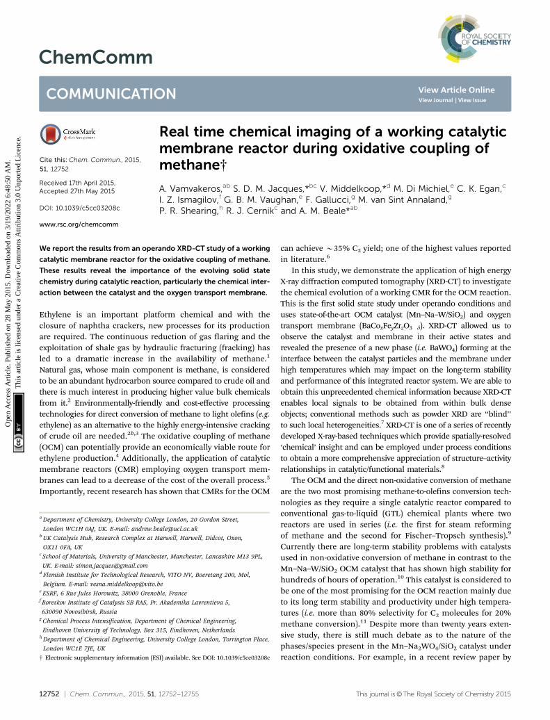
A schematic representation of the CMR is shown at the topleft of Fig. 1; this illustration is produced from absorptioncomputed tomography (micro-CT) data collected before theOCM experiment. XRD-CT was performed at one fixed position,vertically at the middle of the reactor. At the bottom right ofFig. 1, reconstructed XRD-CT images of raw scattered intensityat scattering angle 1.751 are presented. These show the growthof the SiO2 tridymite phase during the operation of the CMRbut serve to illustrate that evolving solid-state chemistry can befollowed. Each XRD-CT reconstructed slice is actually a datacube where each composing voxel (a three dimensional pixel)contains a reconstructed diffraction pattern (see also comment 1in the ESI†).
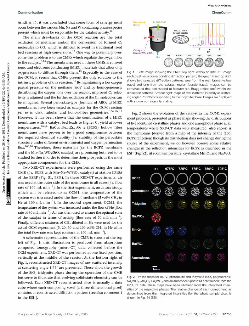
Fig. 2 shows the evolution of the catalyst as the OCM1 experi-ment proceeds, presented as phase maps showing the distributionsof five identified crystalline phases and one amorphous phase at alltemperatures where XRD-CT data were measured. Also shown isthe membrane (derived from a map of the intensity of the (100)BCFZ reflection) though its distribution does not change during thecourse of the experiment; we do however observe some relativechanges in the reflection intensities for BCFZ as described in theESI† (Fig. S2). At room temperature, crystalline Mn2O3 and Na2WO4
Fig. 1 Left: image showing the CMR. Top right: within an XRD-CT imageeach pixel has a corresponding diffraction pattern; the graph inset top rightshows two selected diffraction patterns: one from the membrane (yellowtrace) and one from the catalyst region (purple trace). Images can beconstructed that correspond to features (i.e. Bragg reflections) within thediffraction patterns. Bottom right: maps of raw scattered intensity at scatter-ing angle 1.751 2y corresponding to the tridymite phase. Images are displayedwith a common intensity scaling.
Fig. 2 Phase maps for BCFZ, cristobalite and tridymite (SiO2 polymorphs),Na2WO4, Mn2O3, Ba2WO4 and an amorphous phase as determined from theXRD-CT data. These maps have been obtained from the integrated inten-sities of the respective phases. The relative change of each component, asdetermined from the integrated intensities (for the whole sample slice), isshown in Fig. S4 (ESI†).
Communication ChemComm
Ope
n A
cces
s A
rtic
le. P
ublis
hed
on 2
8 M
ay 2
015.
Dow
nloa
ded
on 3
/19/
2022
6:4
8:50
AM
. T
his
artic
le is
lice
nsed
und
er a
Cre
ativ
e C
omm
ons
Attr
ibut
ion
3.0
Unp
orte
d L
icen
ce.
View Article Online
12754 | Chem. Commun., 2015, 51, 12752--12755 This journal is©The Royal Society of Chemistry 2015
are present in the catalyst particles as expected. The SiO2 supportis clearly visible, principally in a-cristobalite and secondarily intridymite forms. More importantly, the distributions of Mn2O3
and Na2WO4 show that they are not perfectly co-located. At 675 1C,the Na2WO4 phase disappears, which is in agreement with thework of Hou et al., and is coincident with the appearance of anamorphous phase.19 However, a new phase is seen to appearwhich we identify as BaWO4 (using the ICSD and the ICCD PDFcrystallographic databases (Fig. S3, ESI†)). The distribution ofBaWO4 does not match the starting distributions of Na2WO4
but instead concentrated spots of this phase form predominantlyat the catalyst/membrane interface. At 725 1C, Mn2O3 decreasesbut significant amounts of BaWO4 grow which appears to migratetowards the inner wall of the membrane. On reaching 775 1C,Mn2O3 is barely detectable yet more BaWO4 forms, lining almostthe entirety of the inner membrane wall. We note, Mn–BaWO4/SiO2 has been tested in the past as an OCM catalyst and showshigher selectivity to COx than to C2 molecules which suggests thatthe formation of this phase is likely to be detrimental to catalyticperformance.20 On reducing the temperature to 725 1C, Mn2O3 isseen to reform. Against the backdrop of these changes, the SiO2
support is seen to also evolve with continuous growth of tridymite(more than doubling in quantity) and less significant initialgrowth then loss/conversion of cristobalite from tetragonal tocubic forms; this is also in agreement with the work of Houet al. (i.e. a-b transition).19
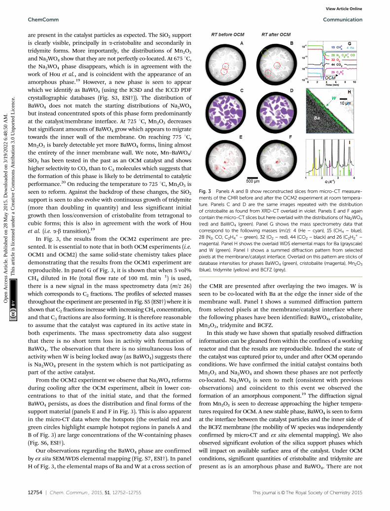
In Fig. 3, the results from the OCM2 experiment are pre-sented. It is essential to note that in both OCM experiments (i.e.OCM1 and OCM2) the same solid-state chemistry takes placedemonstrating that the results from the OCM1 experiment arereproducible. In panel G of Fig. 3, it is shown that when 5 vol%CH4 diluted in He (total flow rate of 100 mL min�1) is used,there is a new signal in the mass spectrometry data (m/z 26)which corresponds to C2 fractions. The profiles of selected massesthroughout the experiment are presented in Fig. S5 (ESI†) where it isshown that C2 fractions increase with increasing CH4 concentration,and that C3 fractions are also forming. It is therefore reasonableto assume that the catalyst was captured in its active state inboth experiments. The mass spectrometry data also suggestthat there is no short term loss in activity with formation ofBaWO4. The observation that there is no simultaneous loss ofactivity when W is being locked away (as BaWO4) suggests thereis Na2WO4 present in the system which is not participating aspart of the active catalyst.
From the OCM2 experiment we observe that Na2WO4 reformsduring cooling after the OCM experiment, albeit in lower con-centrations to that of the initial state, and that the formedBaWO4 persists, as does the distribution and final forms of thesupport material (panels E and F in Fig. 3). This is also apparentin the micro-CT data where the hotspots (the overlaid red andgreen circles highlight example hotspot regions in panels A andB of Fig. 3) are large concentrations of the W-containing phases(Fig. S6, ESI†).
Our observations regarding the BaWO4 phase are confirmedby ex situ SEM/WDS elemental mapping (Fig. S7, ESI†). In panelH of Fig. 3, the elemental maps of Ba and W at a cross section of
the CMR are presented after overlaying the two images. W isseen to be co-located with Ba at the edge the inner side of themembrane wall. Panel I shows a summed diffraction patternfrom selected pixels at the membrane/catalyst interface wherethe following phases have been identified: BaWO4, cristobalite,Mn2O3, tridymite and BCFZ.
In this study we have shown that spatially resolved diffractioninformation can be gleaned from within the confines of a workingreactor and that the results are reproducible. Indeed the state ofthe catalyst was captured prior to, under and after OCM operandoconditions. We have confirmed the initial catalyst contains bothMn2O3 and Na2WO4 and shown these phases are not perfectlyco-located. Na2WO4 is seen to melt (consistent with previousobservations) and coincident to this event we observed theformation of an amorphous component.19 The diffraction signalfrom Mn2O3 is seen to decrease approaching the higher tempera-tures required for OCM. A new stable phase, BaWO4 is seen to format the interface between the catalyst particles and the inner side ofthe BCFZ membrane (the mobility of W species was independentlyconfirmed by micro-CT and ex situ elemental mapping). We alsoobserved significant evolution of the silica support phases whichwill impact on available surface area of the catalyst. Under OCMconditions, significant quantities of cristobalite and tridymite arepresent as is an amorphous phase and BaWO4. There are not
Fig. 3 Panels A and B show reconstructed slices from micro-CT measure-ments of the CMR before and after the OCM2 experiment at room tempera-ture. Panels C and D are the same images repeated with the distributionof cristobalite as found from XRD-CT overlaid in violet. Panels E and F againcontain the micro-CT slices but here overlaid with the distributions of Na2WO4
(red) and BaWO4 (green). Panel G shows the mass spectrometry data thatcorrespond to the following masses (m/z): 4 (He – cyan), 15 (CH4 – blue),28 (N2, CO, C2H4
+ – green), 32 (O2 – red), 44 (CO2 – black) and 26 (C2H2+ –
magenta). Panel H shows the overlaid WDS elemental maps for Ba (grayscale)and W (green). Panel I shows a summed diffraction pattern from selectedpixels at the membrane/catalyst interface. Overlaid on this pattern are sticks ofdatabase intensities for phases BaWO4 (green), cristobalite (magenta), Mn2O3
(blue), tridymite (yellow) and BCFZ (grey).
ChemComm Communication
Ope
n A
cces
s A
rtic
le. P
ublis
hed
on 2
8 M
ay 2
015.
Dow
nloa
ded
on 3
/19/
2022
6:4
8:50
AM
. T
his
artic
le is
lice
nsed
und
er a
Cre
ativ
e C
omm
ons
Attr
ibut
ion
3.0
Unp
orte
d L
icen
ce.
View Article Online
This journal is©The Royal Society of Chemistry 2015 Chem. Commun., 2015, 51, 12752--12755 | 12755
significant quantities of highly crystalline Mn2O3 under OCMbut the loss of highly crystalline Mn2O3 was not accompaniedby any readily observable new amorphous component. Mn2O3
and Na2WO4 reform (albeit in lower final concentrations) postOCM whereas the formed BaWO4 persists. The observation ofthe formation of a stable BaWO4 phase is important since itdemonstrates that the high and uncontrolled mobility of W athigh temperatures is problematic in that: (1) the loss of Wcould impact on the long-term stability of the catalyst, (2) it willalmost certainly lead to the deactivation of the membrane aftermany hours of operation by forming a layer at the membranewall and therefore blocking the flow of oxygen to the catalystbed, (3) and its presence will likely affect the reactor performanceas Mn–BaWO4/SiO2 shows high selectivity to COx.20 Beyond ourexperimental findings for the CMR and its use for the OCMreaction, this also work illustrates the value of these types ofmeasurements in evaluating the performance of a reactor systemfor a chemical reactor engineering-based problem.
The development of the catalysts and membranes for thecatalytic membrane reactor used in this work is funded withinthe DEMCAMER project as part of the European Union SeventhFramework Programme (FP7/2007-2013) under grant agreementno. NMP3-LA-2011-262840. Note: ‘‘The present publications reflectonly the authors’ views and the Union is not liable for any use thatmay be made of the information contained therein.’’ The authorswould like to thank the European Synchrotron Radiation Sourcefor beam time and CerPoTech AS for providing the ceramicpowders. The authors would like to acknowledge support fromthe Hercules Foundation (project ZW09-09) for providingaccess to the FEG-EPMA at MTM-Catholic University of Leuven.Simon Jacques is supported under the EPSRC RCaH ImpactAcceleration Fellowship. The authors Andrew M. Beale andAntonios Vamvakeros are also supported by the EPSRC fund-ing. Paul R. Shearing acknowledges funding from the RoyalAcademy of Engineering.
Notes and references1 R. A. Kerr, Science, 2010, 328, 1624.2 (a) J. H. Lunsford, Catal. Today, 2000, 63, 165; (b) E. McFarland,
Science, 2012, 338, 340.3 P. Tang, Q. Zhu, Z. Wu and D. Ma, Energy Environ. Sci., 2014, 7, 2580.4 H. R. Godini, S. Xiao, S. Jaso, S. Stunkel, D. Salerno, N. X. Son,
S. Song and G. Wozny, Fuel Process. Technol., 2013, 106, 684;Y. Khojasteh Salkuyeh and T. A. Adams, II, Energy Convers. Manage.,2015, 92, 406.
5 J. A. Hugill, F. W. A. Tillemans, J. W. Dijkstra and S. Spoelstra, Appl.Therm. Eng., 2005, 25, 1259.
6 S. Bhatia, C. Y. Thien and A. R. Mohamed, Chem. Eng. J., 2009,148, 525.
7 G. Harding, J. Kosanetzky and U. Neitzel, Med. Phys., 1987, 14, 515;P. Bleuet, E. Welcomme, E. Dooryhee, J. Susini, J. L. Hodeau andP. Walter, Nat. Mater., 2008, 7, 468; S. D. M. Jacques, M. Di Michiel,A. M. Beale, T. Sochi, M. G. O’Brien, L. Espinosa-Alonso, B. M.Weckhuysen and P. Barnes, Angew. Chem., Int. Ed., 2011, 50, 10148;
M. G. O’Brien, S. D. M. Jacques, M. Di Michiel, P. Barnes,B. M. Weckhuysen and A. M. Beale, Chem. Sci., 2012, 3, 509;A. M. Beale, E. K. Gibson, M. G. O’Brien, S. D. M. Jacques, R. J.Cernik, M. D. Michiel, P. D. Cobden, O. Pirgon-Galin, L. V. D. Water,M. J. Watson and B. M. Weckhuysen, J. Catal., 2014, 314, 94;A. M. Beale, S. D. M. Jacques, E. K. Gibson and M. Di Michiel,Coord. Chem. Rev., 2014, 277, 208.
8 F. Basile, P. Benito, S. Bugani, W. De Nolf, G. Fornasari, K. Janssens,L. Morselli, E. Scavetta, D. Tonelli and A. Vaccari, Adv. Funct. Mater.,2010, 20, 4117; I. L. C. Buurmans and B. M. Weckhuysen, Nat.Chem., 2012, 4, 873; J.-D. Grunwaldt, J. B. Wagner and R. E. Dunin-Borkowski, ChemCatChem, 2013, 5, 62; S. D. M. Jacques, M. Di Michiel,S. A. Kimber, X. Yang, R. J. Cernik, A. M. Beale and S. J. Billinge, Nat.Commun., 2013, 4, 2536; S. W. Price, K. Ignatyev, K. Geraki, M. Basham,J. Filik, N. T. Vo, P. T. Witte, A. M. Beale and J. F. Mosselmans, Phys.Chem. Chem. Phys., 2015, 17, 521–529.
9 J. H. Lunsford, Angew. Chem., Int. Ed. Engl., 1995, 34, 970; Q. Zhu,S. L. Wegener, C. Xie, O. Uche, M. Neurock and T. J. Marks, Nat.Chem., 2013, 5, 104; X. Guo, G. Fang, G. Li, H. Ma, H. Fan, L. Yu,C. Ma, X. Wu, D. Deng, M. Wei, D. Tan, R. Si, S. Zhang, J. Li, L. Sun,Z. Tang, X. Pan and X. Bao, Science, 2014, 344, 616; M. Ruitenbeekand B. M. Weckhuysen, Angew. Chem., Int. Ed., 2014, 53, 11137;P. Schwach, M. G. Willinger, A. Trunschke and R. Schlogl, Angew.Chem., Int. Ed., 2013, 52, 11381.
10 X. Fang, S. Li, J. Lin and Y. Chu, J. Mol. Catal., 1992, 6, 427; X. P.Fang, S. B. Li, J. Z. Lin, J. F. Gu and D. X. Yang, J. Mol. Catal., 1992,6, 255; Y. Kou, B. Zhang, J.-z. Niu, S.-b. Li, H.-l. Wang, T. Tanaka andS. Yoshida, J. Catal., 1998, 173, 399; J. J. Spivey and G. Hutchings,Chem. Soc. Rev., 2014, 43, 792.
11 D. J. Wang, M. P. Rosynek and J. H. Lunsford, J. Catal., 1995,155, 390.
12 S. Arndt, T. Otremba, U. Simon, M. Yildiz, H. Schubert andR. Schomacker, Appl. Catal., A, 2012, 425–426, 53.
13 L. Luo, X. Tang, W. Wang, Y. Wang, S. Sun, F. Qi and W. Huang, Sci.Rep., 2013, 3, 1625; K. Takanabe and E. Iglesia, Angew. Chem., Int.Ed., 2008, 47, 7689.
14 H. Wang, Y. Cong and W. Yang, Catal. Today, 2005, 104, 160.15 (a) Y. Teraoka, H.-M. Zhang, S. Furukawa and N. Yamazoe, Chem.
Lett., 1985, 1743; (b) X. Dong, W. Jin, N. Xu and K. Li, Chem. Commun.,2011, 47, 10886.
16 (a) X. Tan, Z. Pang, Z. Gu and S. Liu, J. Membr. Sci., 2007, 302, 109;(b) O. Czuprat, T. Schiestel, H. Voss and J. Caro, Ind. Eng. Chem. Res.,2010, 49, 10230; (c) X. Tan and K. Li, Curr. Opin. Chem. Eng., 2011,1, 69.
17 Z. Cao, H. Jiang, H. Luo, S. Baumann, W. A. Meulenberg, J. Assmann,L. Mleczko, Y. Liu and J. Caro, Angew. Chem., Int. Ed. Engl., 2013,52, 13794; Y. Wei, W. Yang, J. Caro and H. Wang, Chem. Eng. J., 2013,220, 185; H. Jiang, Z. Cao, S. Schirrmeister, T. Schiestel and J. Caro,Angew. Chem., Int. Ed., 2010, 49, 5656; J. E. ten Elshof, B. A. van Hasseland H. J. M. Bouwmeester, Catal. Today, 1995, 25, 397; J. E. tenElshof, H. J. M. Bouwmeester and H. Verweij, Appl. Catal., A, 1995,130, 195; S. J. Xu and W. J. Thomson, AIChE J., 1997, 43, 2731; Y. Zeng,Y. S. Lin and S. L. Swartz, J. Membr. Sci., 1998, 150, 87; W. Wang andY. S. Lin, J. Membr. Sci., 1995, 103, 219; X. Tan and K. Li, Ind. Eng.Chem. Res., 2006, 45, 142; F. R. Garcıa-Garcıa, B. F. K. Kingsbury,M. A. Rahman and K. Li, Catal. Today, 2012, 193, 20.
18 J. Tong, W. Yang, B. Zhu and R. Cai, J. Membr. Sci., 2002, 203, 175;T. Schiestel, M. Kilgus, S. Peter, K. J. Caspary, H. Wang and J. Caro,J. Membr. Sci., 2005, 258, 1; C. Tablet, G. Grubert, H. Wang,T. Schiestel, M. Schroeder, B. Langanke and J. Caro, Catal. Today,2005, 104, 126; K. Efimov, O. Czuprat and A. Feldhoff, J. Solid StateChem., 2011, 184, 1085; S. M. Hashim, A. R. Mohamed and S. Bhatia,Adv. Colloid Interface Sci., 2010, 160, 88.
19 S. Hou, Y. Cao, W. Xiong, H. Liu and Y. Kou, Ind. Eng. Chem. Res.,2006, 45, 7077.
20 S. Ji, T. Xiao, S. Li, L. Chou, B. Zhang, C. Xu, R. Hou, A. P. E. Yorkand M. L. H. Green, J. Catal., 2003, 220, 47.
Communication ChemComm
Ope
n A
cces
s A
rtic
le. P
ublis
hed
on 2
8 M
ay 2
015.
Dow
nloa
ded
on 3
/19/
2022
6:4
8:50
AM
. T
his
artic
le is
lice
nsed
und
er a
Cre
ativ
e C
omm
ons
Attr
ibut
ion
3.0
Unp
orte
d L
icen
ce.
View Article Online