Embed Size (px)
Citation preview
Return to Web Version
Materials Issues in Polymer Electrolyte Membrane Fuel Cells
By: Nancy L. Garland, Thomas G. Benjamin, John P. Kopasz, Material Matters 2008, 3.4, 85.
Introduction
Fuel cells have the potential to reduce the nation’s energy use through increased energy conversion efficiency and dependence on imported petroleum by the use of hydrogen from renewable resources. The US DOE Fuel Cell subprogram emphasizes polymer electrolyte membrane (PEM) fuel cells as replacements for internal combustion engines in light-duty vehicles to support the goal of reducing oil use in the transportation sector. PEM fuel cells are the focus for light-duty vehicles because they are capable of rapid start-up, demonstrate high operating efficiency, and can operate at low temperatures.
The program also supports fuel cells for stationary power, portable power, and auxiliary power applications where earlier market entry would assist in the development of a fuel cell manufacturing and supplier base. The technical focus is on developing materials and components that enable fuel cells to achieve the fuel cell subprogram objectives, primarily related to system cost and durability.
For transportation applications, the performance and cost of a fuel cell vehicle must be comparable or superior to today’s gasoline vehicles to achieve widespread penetration into the market and achieve the desired reduction in petroleum consumption. By translating vehicle performance requirements into fuel cell system needs, DOE has defined technical targets for 2010 and 2015. These targets are based on competitiveness with current internal combustion engine vehicles in terms of vehicle performance and cost, while providing improvements in efficiency of a factor of 2.5 to 3. The overall system targets are: a 60% peak-efficient, durable, direct hydrogen fuel cell power system for transportation at a cost of $45/kW by 2010 and $30/kW by 2015.
DOE’s approach to achieving these technical and cost targets is to improve existing materials and to identify and qualify new materials.
Fuel Cell Description
A fuel cell electrocatalytically generates electricity in a manner analogous to batteries. However, in a fuel cell the electrodes are not consumed. Rather, a fuel cell consumes fuel (hydrogen for PEM fuel cells) at the anode and oxygen from the air at the cathode.
A catalyst is utilized at the anode to promote separation of the hydrogen’s protons and electrons. The protons travel through a membrane material to the cathode while the electrons travel via an external circuit to the cathode where they combine with the protons and oxygen on the cathode catalyst to form water and complete the cycle. The combination of the anode/membrane/ cathode layers is called the membrane electrode assembly (MEA).
To complete a cell, the MEA is usually sandwiched between gas diffusion layers and gas flow fields that distribute reactants to the electrodes and collect the current from the reaction. Each cell generates less than a volt so many cells are “stacked” in series to generate voltage at useful levels.
Current PEM Fuel Cell Materials
Nancy L. Garland*1, Thomas G.
Benjamin2 and John P. Kopasz2
1 U.S. Department of Energy,
1000 Independence Avenue,
S.W., Washington, D.C. 20585-
0121 2 Argonne National Laboratory,
9700 South Cass Avenue,
Lemont, IL 60439
*E-mail:
Page 1 of 9
11/29/2011Page 1 of 9
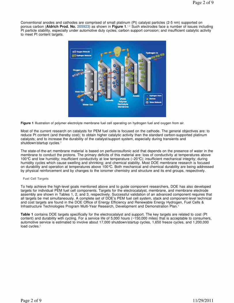
Conventional anodes and cathodes are comprised of small platinum (Pt) catalyst particles (2-5 nm) supported on porous carbon (Aldrich Prod. No. 205923) as shown in Figure 1.1,2 Such electrodes face a number of issues including Pt particle stability, especially under automotive duty cycles; carbon support corrosion; and insufficient catalytic activity to meet Pt content targets.
Figure 1 Illustration of polymer electrolyte membrane fuel cell operating on hydrogen fuel and oxygen from air.
Most of the current research on catalysts for PEM fuel cells is focused on the cathode. The general objectives are: to reduce Pt content (and thereby cost); to obtain higher catalytic activity than the standard carbon-supported platinum catalysts; and to increase the durability of the catalyst/support system, especially during transients and shutdown/startup cycles.3
The state-of-the-art membrane material is based on perfluorosulfonic acid that depends on the presence of water in the membrane to conduct the protons. The primary deficits of this material are: loss of conductivity at temperatures above 100°C and low humidity; insufficient conductivity at low temperature (–20°C); insufficient mechanical integrity; during humidity cycles which cause swelling and shrinking; and chemical stability. Most DOE membrane research is focused on durability and operation at temperatures above 100°C. Both mechanical and chemical durability are being addressed by physical reinforcement and by changes to the ionomer chemistry and structure and its end groups, respectively.
Fuel Cell Targets
To help achieve the high-level goals mentioned above and to guide component researchers, DOE has also developed targets for individual PEM fuel cell components. Targets for the electrocatalyst, membrane, and membrane electrode assembly are shown in Tables 1, 2, and 3, respectively. Successful validation of an advanced component requires that all targets be met simultaneously. A complete set of DOE’s PEM fuel cell system, stack and component-level technical and cost targets are found in the DOE Office of Energy Efficiency and Renewable Energy Hydrogen, Fuel Cells & Infrastructure Technologies Program Multi-Year Research, Development and Demonstration Plan.4
Table 1 contains DOE targets specifically for the electrocatalyst and support. The key targets are related to cost (Pt content) and durability with cycling. For a service life of 5,000 hours (~150,000 miles) that is acceptable to consumers, automotive service is estimated to involve about 17,000 shutdown/startup cycles, 1,650 freeze cycles, and 1,200,000 load cycles.5
Page 2 of 9
11/29/2011Page 2 of 9
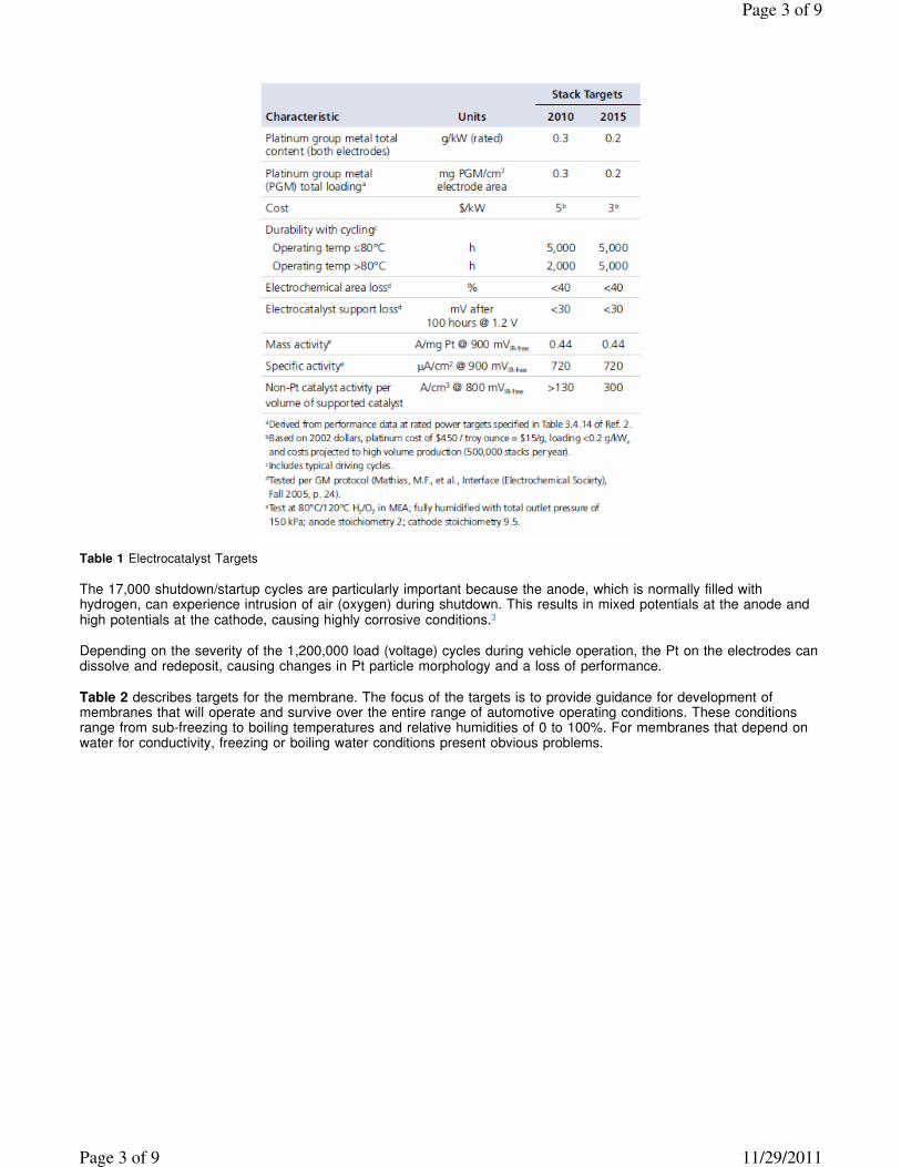
Table 1 Electrocatalyst Targets
The 17,000 shutdown/startup cycles are particularly important because the anode, which is normally filled with hydrogen, can experience intrusion of air (oxygen) during shutdown. This results in mixed potentials at the anode and high potentials at the cathode, causing highly corrosive conditions.3
Depending on the severity of the 1,200,000 load (voltage) cycles during vehicle operation, the Pt on the electrodes can dissolve and redeposit, causing changes in Pt particle morphology and a loss of performance.
Table 2 describes targets for the membrane. The focus of the targets is to provide guidance for development of membranes that will operate and survive over the entire range of automotive operating conditions. These conditions range from sub-freezing to boiling temperatures and relative humidities of 0 to 100%. For membranes that depend on water for conductivity, freezing or boiling water conditions present obvious problems.
Page 3 of 9
11/29/2011Page 3 of 9
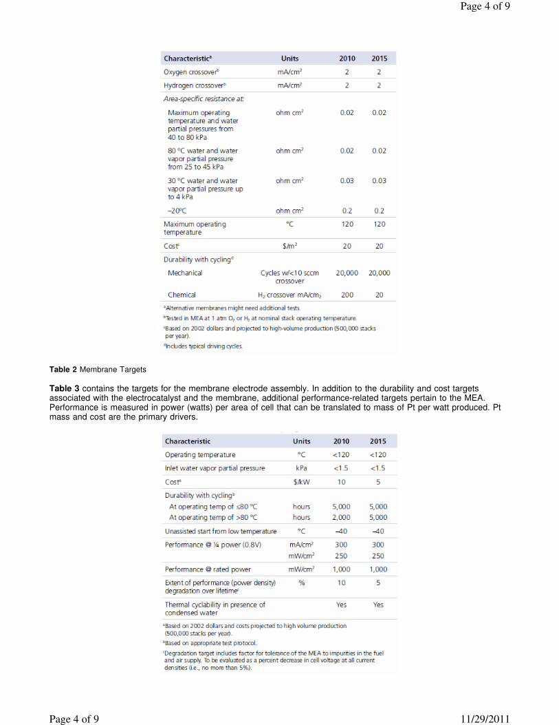
Table 2 Membrane Targets
Table 3 contains the targets for the membrane electrode assembly. In addition to the durability and cost targets associated with the electrocatalyst and the membrane, additional performance-related targets pertain to the MEA. Performance is measured in power (watts) per area of cell that can be translated to mass of Pt per watt produced. Pt mass and cost are the primary drivers.
Page 4 of 9
11/29/2011Page 4 of 9
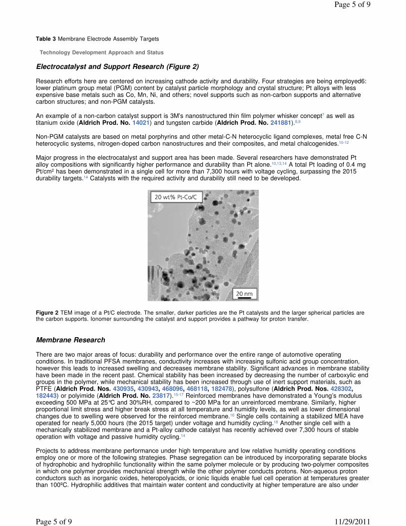
Table 3 Membrane Electrode Assembly Targets
Technology Development Approach and Status
Electrocatalyst and Support Research (Figure 2)
Research efforts here are centered on increasing cathode activity and durability. Four strategies are being employed6: lower platinum group metal (PGM) content by catalyst particle morphology and crystal structure; Pt alloys with less expensive base metals such as Co, Mn, Ni, and others; novel supports such as non-carbon supports and alternative carbon structures; and non-PGM catalysts.
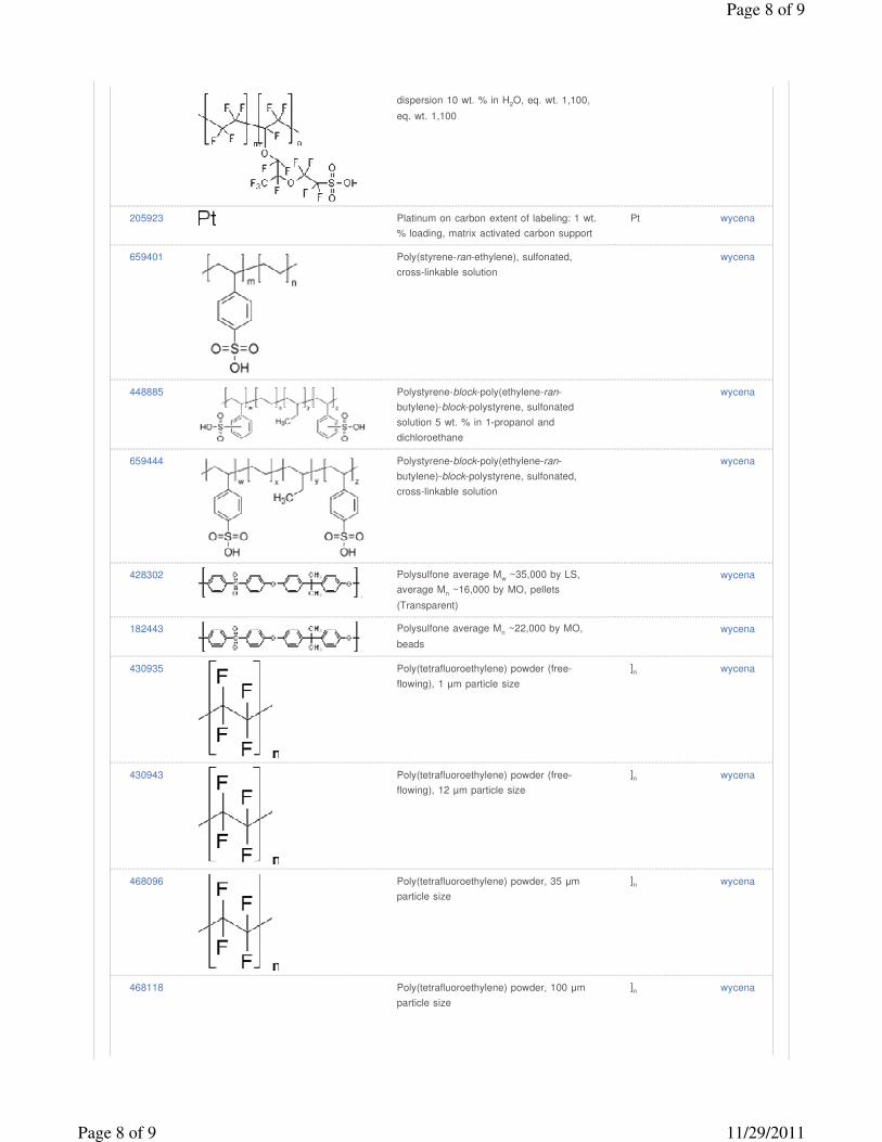
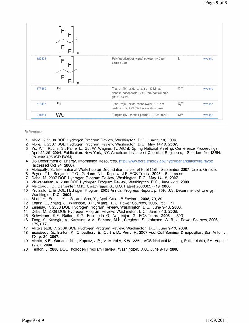
An example of a non-carbon catalyst support is 3M’s nanostructured thin film polymer whisker concept7 as well as titanium oxide (Aldrich Prod. No. 14021) and tungsten carbide (Aldrich Prod. No. 241881).8,9
Non-PGM catalysts are based on metal porphyrins and other metal-C-N heterocyclic ligand complexes, metal free C-N heterocyclic systems, nitrogen-doped carbon nanostructures and their composites, and metal chalcogenides.10-12
Major progress in the electrocatalyst and support area has been made. Several researchers have demonstrated Pt alloy compositions with significantly higher performance and durability than Pt alone.10,13,14 A total Pt loading of 0.4 mg Pt/cm2 has been demonstrated in a single cell for more than 7,300 hours with voltage cycling, surpassing the 2015 durability targets.14 Catalysts with the required activity and durability still need to be developed.
Figure 2 TEM image of a Pt/C electrode. The smaller, darker particles are the Pt catalysts and the larger spherical particles are the carbon supports. Ionomer surrounding the catalyst and support provides a pathway for proton transfer.
Membrane Research
There are two major areas of focus: durability and performance over the entire range of automotive operating conditions. In traditional PFSA membranes, conductivity increases with increasing sulfonic acid group concentration, however this leads to increased swelling and decreases membrane stability. Significant advances in membrane stability have been made in the recent past. Chemical stability has been increased by decreasing the number of carboxylic end groups in the polymer, while mechanical stability has been increased through use of inert support materials, such as PTFE (Aldrich Prod. Nos. 430935, 430943, 468096, 468118, 182478), polysulfone (Aldrich Prod. Nos. 428302, 182443) or polyimide (Aldrich Prod. No. 23817).15-17 Reinforced membranes have demonstrated a Young’s modulus exceeding 500 MPa at 25°C and 30%RH, compared to ~200 MPa for an unreinforced membrane. Similarly, higher proportional limit stress and higher break stress at all temperature and humidity levels, as well as lower dimensional changes due to swelling were observed for the reinforced membrane.16 Single cells containing a stabilized MEA have operated for nearly 5,000 hours (the 2015 target) under voltage and humidity cycling.18 Another single cell with a mechanically stabilized membrane and a Pt-alloy cathode catalyst has recently achieved over 7,300 hours of stable operation with voltage and passive humidity cycling.14
Projects to address membrane performance under high temperature and low relative humidity operating conditions employ one or more of the following strategies. Phase segregation can be introduced by incorporating separate blocks of hydrophobic and hydrophilic functionality within the same polymer molecule or by producing two-polymer composites in which one polymer provides mechanical strength while the other polymer conducts protons. Non-aqueous proton conductors such as inorganic oxides, heteropolyacids, or ionic liquids enable fuel cell operation at temperatures greater than 100ºC. Hydrophilic additives that maintain water content and conductivity at higher temperature are also under
Page 5 of 9
11/29/2011Page 5 of 9
consideration.19 Several researchers have achieved DOE’s interim conductivity goal of 70 mS/cm at 30ºC and 80% relative humidity.20
Summary
Fuel cell systems are already being demonstrated in prototype vehicles, consumer electronics devices, materials handling equipment, and backup power and other stationary applications. Finally, the performance of the fuel cell system must be comparable in all respects to incumbent technologies, whether it is an internal combustion engine powering an automobile, a diesel generator set providing distributed generation, or a lithium-ion battery powering a consumer electronics device. While many promising new approaches have been developed in the last two years, technical challenges remain to achieve the upcoming 2010 and the ultimate 2015 system targets.
Materials
Product
#
Image Description
Molecular
Formula
Add to
Cart
454737 Nafion® 350 perfluorinated membrane,
reinforced with PTFE, thickness 0.01 in.
wycena
541346 Nafion® perfluorinated membrane Nafion®
115, thickness 0.005 in.
wycena
274674 Nafion® perfluorinated membrane Nafion®
117, thickness 0.007 in.
wycena
292567 Nafion® perfluorinated membrane Nafion®
117, thickness 0.007 in.
wycena
565067 Nafion® perfluorinated membrane Nafion®
324, reinforced with poly(tetrafluoroethylene)
fiber, thickness 0.006 in.
wycena
564664 Nafion® perfluorinated membrane Nafion®
N551PW, reinforced with poly
(tetrafluoroethylene) fiber, thickness
0.005 in.
wycena
Page 6 of 9
11/29/2011Page 6 of 9
676470 Nafion® perfluorinated membrane Nafion®
NRE-212, thickness 0.002 in.
wycena
527084 Nafion® perfluorinated resin solution 5 wt. %
in mixture of lower aliphatic alcohols and
water, contains 45% water
wycena
510211 Nafion® perfluorinated resin solution 5 wt. %
in mixture of lower aliphatic alcohols and
water, contains 45% water
wycena
663492 Nafion® perfluorinated resin solution 20 wt.
% in lower aliphatic alcohols and water,
contains 34% water
wycena
527122 Nafion® perfluorinated resin solution 20 wt.
% in mixture of lower aliphatic alcohols and
water, contains 34% water
wycena
274704 Nafion® perfluorinated resin solution 5 wt. %
in lower aliphatic alcohols and water,
contains 15-20% water
wycena
527114 Nafion® perfluorinated resin, aqueous
dispersion 10 wt. % in H2O, eq. wt. 1,000,
eq. wt. 1,000
wycena
527106 Nafion® perfluorinated resin, aqueous wycena
Page 7 of 9
11/29/2011Page 7 of 9
dispersion 10 wt. % in H2O, eq. wt. 1,100,
eq. wt. 1,100
205923 Platinum on carbon extent of labeling: 1 wt.
% loading, matrix activated carbon support
Pt wycena
659401 Poly(styrene-ran-ethylene), sulfonated,
cross-linkable solution
wycena
448885 Polystyrene-block-poly(ethylene-ran-
butylene)-block-polystyrene, sulfonated
solution 5 wt. % in 1-propanol and
dichloroethane
wycena
659444 Polystyrene-block-poly(ethylene-ran-
butylene)-block-polystyrene, sulfonated,
cross-linkable solution
wycena
428302 Polysulfone average Mw ~35,000 by LS,
average Mn ~16,000 by MO, pellets
(Transparent)
wycena
182443 Polysulfone average Mn ~22,000 by MO,
beads
wycena
430935 Poly(tetrafluoroethylene) powder (free-
flowing), 1 µm particle size
]n wycena
430943 Poly(tetrafluoroethylene) powder (free-
flowing), 12 µm particle size
]n wycena
468096 Poly(tetrafluoroethylene) powder, 35 µm
particle size
]n wycena
468118 Poly(tetrafluoroethylene) powder, 100 µm
particle size
]n wycena
Page 8 of 9
11/29/2011Page 8 of 9
References
1. More, K. 2008 DOE Hydrogen Program Review, Washington, D.C., June 9-13, 2008. 2. More, K. 2007 DOE Hydrogen Program Review, Washington, D.C., May 14-19, 2007. 3. Yu, P.T., Kocha, S., Paine, L., Gu, W, Wagner, F., AIChE Spring National Meeting: Conference Proceedings,
April 25-29, 2004. Publication: New York, NY: American Institute of Chemical Engineers, - Standard No: ISBN: 0816909423 (CD-ROM).
4. US Department of Energy. Information Resources. http://www.eere.energy.gov/hydrogenandfuelcells/mypp (accessed Oct 24, 2008).
5. Motupally, S., International Workshop on Degradation Issues of Fuel Cells, September 2007, Crete, Greece. 6. Payne, T.L., Benjamin, T.G., Garland, N.L., Kopasz, J.P. ECS Trans., 2008, 16, in press. 7. Debe, M. 2007 DOE Hydrogen Program Review, Washington, D.C., May 14-18, 2007. 8. Viswanathan, V. 2008 DOE Hydrogen Program Review, Washington, D.C., June 9-13, 2008. 9. Merzougui, B., Carpenter, M.K., Swathirajan, S., U.S. Patent 20060257719, 2006.
10. Protsailo, L. in DOE Hydrogen Program 2005 Annual Progress Report, p. 739, U.S. Department of Energy, Washington D.C., 2005.
11. Shao, Y., Sui, J., Yin, G., and Gao, Y., Appl. Catal. B-Environ., 2008, 79, 89. 12. Zhang, L., Zhang, J., Wilkinson, D.P., Wang, H., J. Power Sources, 2006, 156, 171. 13. Zelenay, P. 2008 DOE Hydrogen Program Review, Washington, D.C., June 9-13, 2008. 14. Debe, M. 2008 DOE Hydrogen Program Review, Washington, D.C., June 9-13, 2008. 15. Schwiebert, K.E., Raiford, K.G., Escobedo, G., Nagarajan, G., ECS Trans., 2006, 1, 303. 16. Tang, Y., Kusoglu, A., Karlsson, A.M., Santare, M.H., Cleghorn, S., Johnson, W. B., J. Power Sources, 2008,
175, 817. 17. Mittelsteadt, C. 2008 DOE Hydrogen Program Review, Washington, D.C., June 9-13, 2008. 18. Escobedo, G., Barton, K., Choudhury, B., Curtin, D., Perry, R. 2007 Fuel Cell Seminar & Exposition, San Antonio,
TX, p. 20, 2007. 19. Martin, K.E., Garland, N.L., Kopasz, J.P., McMurphy, K.W. 236th ACS National Meeting, Philadelphia, PA, August
17-21, 2008. 20. Fenton, J. 2008 DOE Hydrogen Program Review, Washington, D.C., June 9-13, 2008.
182478 Poly(tetrafluoroethylene) powder, >40 µm
particle size
]n wycena
677469 Titanium(IV) oxide contains 1% Mn as
dopant, nanopowder, <100 nm particle size
(BET), ≥97%
O2Ti wycena
718467 Titanium(IV) oxide nanopowder, ~21 nm
particle size, ≥99.5% trace metals basis
O2Ti wycena
241881 Tungsten(IV) carbide powder, 10 µm, 99% CW wycena
Page 9 of 9
11/29/2011Page 9 of 9