Embed Size (px)
Citation preview
WelcomeYou have selected one of the finest marine power packages available. It incorporates numerous design features toensure operating ease and durability.With proper care and maintenance, you will enjoy using this product for many boating seasons. To ensure maximumperformance and carefree use, we ask that you thoroughly read this manual.The Operation and Maintenance Manual contains specific instructions for using and maintaining your product. Wesuggest that this manual remain with the product for ready reference whenever you are on the water.Thank you for purchasing one of our products. We sincerely hope your boating will be pleasant!Mercury Marine, Fond du Lac, Wisconsin, U.S.A.
Name / function:John Pfeifer, President,Mercury Marine
Read This Manual ThoroughlyIMPORTANT: If you do not understand any portion of this manual, contact your dealer. Your dealer can also provide ademonstration of actual starting and operating procedures.
NoticeThroughout this publication, and on your power package, warnings, cautions, and notices, accompanied by the
International Hazard Symbol ! , may be used to alert the installer and user to special instructions concerning aparticular service or operation that may be hazardous if performed incorrectly or carelessly. Observe them carefully.These safety alerts alone cannot eliminate the hazards that they signal. Strict compliance with these special instructionswhile performing the service, plus common sense operation, are major accident prevention measures.
! WARNINGIndicates a hazardous situation which, if not avoided, could result in death or serious injury.
! CAUTIONIndicates a hazardous situation which, if not avoided, could result in minor or moderate injury.
NOTICEIndicates a situation which, if not avoided, could result in engine or major component failure.
IMPORTANT: Identifies information essential to the successful completion of the task.NOTE: Indicates information that helps in the understanding of a particular step or action.IMPORTANT: The operator (driver) is responsible for the correct and safe operation of the boat, the equipment aboard,and the safety of all occupants aboard. We strongly recommend that the operator read this Operation and MaintenanceManual and thoroughly understand the operational instructions for the power package and all related accessories beforethe boat is used.
! WARNINGThe engine exhaust from this product contains chemicals known to the state of California to cause cancer, birthdefects or other reproductive harm.
The serial numbers are the manufacturer’s keys to numerous engineering details that apply to your Mercury Marinepower package. When contacting Mercury Marine about service, always specify model and serial numbers.Descriptions and specifications contained herein were in effect at the time this was approved for printing. MercuryMarine, whose policies are based on continuous improvement, reserves the right to discontinue models at any time or tochange specifications or designs without notice and without incurring obligation.
© 2
017
Mer
cury
Mar
ine
4.5L
, 6.2
L M
PI8M
0128
973
51
7en
g
Warranty MessageThe product you have purchased comes with a limited warranty from Mercury Marine; the terms of the warranty are set forthin the Warranty Manual included with the product. The Warranty Manual contains a description of what is covered, what is notcovered, the duration of coverage, how to best obtain warranty coverage, important disclaimers and limitations ofdamages, and other related information. Please review this important information.Mercury Marine products are designed and manufactured to comply with our own high quality standards, applicable industrystandards and regulations, as well as certain emissions regulations. At Mercury Marine every engine is operated and testedbefore it is boxed for shipment to make sure that the product is ready for use. In addition, certain Mercury Marine products aretested in a controlled and monitored environment, for up to 10 hours of engine run time, in order to verify and make a record ofcompliance with applicable standards and regulations. All Mercury Marine product, sold as new, receives the applicable limitedwarranty coverage, whether the engine participated in one of the test programs described above or not.
Copyright and Trademark Information© MERCURY MARINE. All rights reserved. Reproduction in whole or in part without permission is prohibited.Alpha, Axius, Bravo One, Bravo Two, Bravo Three, Circle M with Waves Logo, K‑planes, Mariner, MerCathode, MerCruiser,Mercury, Mercury with Waves Logo, Mercury Marine, Mercury Precision Parts, Mercury Propellers, Mercury Racing,MotorGuide, OptiMax, Quicksilver, SeaCore, Skyhook, SmartCraft, Sport‑Jet, Verado, VesselView, Zero Effort, Zeus, #1 On theWater and We're Driven to Win are registered trademarks of Brunswick Corporation. Pro XS is a trademark of BrunswickCorporation. Mercury Product Protection is a registered service mark of Brunswick Corporation.
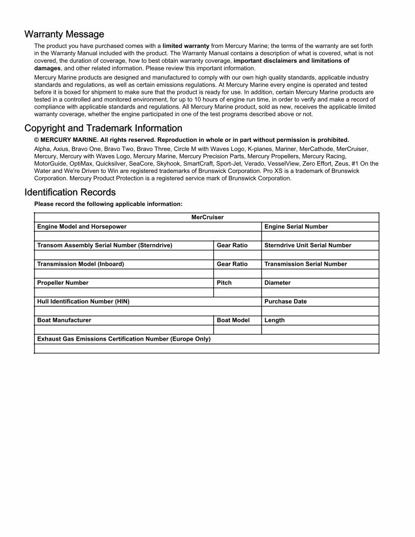
Identification RecordsPlease record the following applicable information:
MerCruiserEngine Model and Horsepower Engine Serial Number Transom Assembly Serial Number (Sterndrive) Gear Ratio Sterndrive Unit Serial Number Transmission Model (Inboard) Gear Ratio Transmission Serial Number Propeller Number Pitch Diameter Hull Identification Number (HIN) Purchase Date Boat Manufacturer Boat Model Length Exhaust Gas Emissions Certification Number (Europe Only)
TABLE OF CONTENTS
Section 1 - Getting to Know Your Power Package
Adaptive Speed Control (ASC).................................................. 2Additional Operation Instructions for Joystick Piloting Sterndrive(JPS).......................................................................................... 2Identification............................................................................... 2
Engine Serial Number ........................................................ 2Alpha Sterndrive Serial Number......................................... 3Alpha Transom Serial Number........................................... 3Bravo Sterndrive Serial Number and Identification............. 4Bravo Transom Serial Number........................................... 4
Lanyard Stop Switch.................................................................. 5Keep the Lanyard Stop Switch and Lanyard Cord in GoodOperating Condition............................................................. 6
Instrumentation.......................................................................... 6VesselView........................................................................... 6SmartCraft Digital Instruments............................................. 6System Link Digital Instruments........................................... 7
Remote Controls (Non‑DTS Models)......................................... 8Remote Control Features—Non‑DTS................................. 8
Gear Shifting...................................................................8Remote Controls (DTS Models)................................................. 9
Remote Controls................................................................. 9Panel Mount Features........................................................ 9DTS Slim Binnacle Single Handle Console Features andOperation............................................................................ 9
Special Digital Throttle and Shift (DTS) Features.........10Dual‑Handle Electronic Remote Control (ERC)—Operationand Adjustment................................................................. 11
Operation...................................................................... 11Adjustment....................................................................11
Special Digital Throttle and Shift (DTS) Features............. 12Dock............................................................................. 13Throttle Only................................................................. 131 Lever..........................................................................14Sync..............................................................................14Transfer (Boats Equipped with Dual Helms)................ 15
Helm Transfer................................................................... 15Zero Effort Features.......................................................... 15
Power Trim............................................................................... 16Single Engine Trim/Trailer.................................................. 17Dual Engine Trim/Trailer.................................................... 17
Electrical System Overload Protection..................................... 17Visual and Audio Warning Systems......................................... 19
Service Engine Light and OBD‑M MIL Kit......................... 19Testing the OBD‑M Malfunction Indicator Lamp(MIL)............................................................................. 20
Audio Warning System..................................................... 20Caution......................................................................... 20Critical...........................................................................20Nonconfigured Alarm–DTS Only.................................. 20Testing the Audio Warning System.............................. 21
Guardian Strategy............................................................. 21
Section 2 - On the Water
Additional Operation Instructions for Joystick Piloting Sterndrive(JPS)........................................................................................ 24Safe Boating Recommendations............................................. 24Carbon Monoxide Exposure.................................................... 25
Be Alert To Carbon Monoxide Poisoning........................... 25Stay Clear of Exhaust Areas.............................................. 25Good Ventilation ................................................................ 25Poor Ventilation ................................................................. 26
Basic Boat Operation .............................................................. 26Launching and Boat Operation......................................... 26
Operation Chart............................................................ 26Starting and Stopping the Engine..................................... 27
Starting the Engine....................................................... 27Stopping the Engine..................................................... 28
Starting the Engine After It Has Stopped While In Gear—Non‑DTS Applications...................................................... 28Throttle Only Operation.................................................... 28Trailering the Boat............................................................ 28Freezing Temperature Operation..................................... 28Drain Plug and Bilge Pump............................................... 28
Protecting People in the Water................................................ 29While You Are Cruising...................................................... 29While Boat Is Stationary..................................................... 29
High‑Speed and High‑Performance Operation........................ 29Passenger Safety in Pontoon Boats and Deck Boats.............. 29
Boats Having an Open Front Deck.....................................29Boats With Front‑Mounted, Raised Pedestal Fishing Seats........................................................................................... 29
Wave and Wake Jumping........................................................ 30Impact with Underwater Hazards............................................. 30
Drive Unit Impact Protection...............................................31Operating with Low Water Inlets in Shallow Water.................. 31Conditions Affecting Operation................................................ 31
Weight Distribution (Passengers and Gear) Inside theBoat.................................................................................. 31The Bottom of the Boat..................................................... 32Cavitation.......................................................................... 32Ventilation......................................................................... 32Elevation and Climate....................................................... 32Propeller Selection............................................................ 32
General Information...................................................... 32Engine RPM Limiter......................................................33
Getting Started......................................................................... 3320‑Hour Break‑In Period................................................... 33After the Break‑In Period.................................................. 33End of First Season Checkup........................................... 33
90-8M0128973 eng MAY 2017 Page i
Section 3 - Specifications
Fuel Requirements................................................................. 36Fuel Ratings...................................................................... 36Using Reformulated (Oxygenated) Gasoline (USA Only).......................................................................................... 36Gasoline Containing Alcohol............................................. 36
Bu16 Butanol Fuel Blends.......................................... 36Methanol and Ethanol Fuel Blends............................. 36
Engine Oil............................................................................... 36Engine Specifications............................................................. 37
4.5L MPI Engine Specifications....................................... 376.2L MPI Engine Specifications....................................... 38
Fluid Specifications................................................................. 38Engine............................................................................. 38Alpha Sterndrive.............................................................. 39Bravo Sterndrives............................................................ 39Power‑Assisted Steering and Power Trim Fluids............ 39
Approved Power‑Assisted Steering Fluids.................. 39Approved Power Trim Fluids....................................... 39
Section 4 - Maintenance
Service Decals........................................................................ 42Closed Cooling Service Decals ‑ Alpha and Bravo Drive.......................................................................................... 42Bravo Standard Cooling Service Decal............................ 42Alpha Standard Cooling Service Decal............................. 43
Additional Operation Instructions for Joystick PilotingSterndrive (JPS)..................................................................... 43Owner/Operator Responsibilities............................................ 43Dealer Responsibilities........................................................... 43Maintenance........................................................................... 43Do‑It‑Yourself Maintenance Suggestions............................... 44Inspection............................................................................... 44MerCruiser Gas Sterndrive Inspection and MaintenanceSchedule................................................................................. 44
Daily Checks..................................................................... 44After Each Use.................................................................. 45Weekly Checks................................................................. 45Every Two Months or 50 Hours........................................ 45Annually or 100 Hours...................................................... 45Three Years or 300 Hours................................................ 45Five Years or 500 Hours................................................... 46
Engine Oil............................................................................... 46Checking......................................................................... 46
Oil Level—Overfilled................................................... 46Filling............................................................................... 46Changing Oil and Filter.................................................... 47Engine Oil Drain Pump.................................................... 47Changing Filter................................................................ 48
Power Steering Fluid.............................................................. 48Checking........................................................................... 48Filling................................................................................ 49Changing.......................................................................... 49
Engine Coolant ‑ Closed‑Cooling........................................... 49Checking......................................................................... 49Filling............................................................................... 50Changing ........................................................................ 50
Alpha Sterndrive Gear Lube................................................... 51Checking........................................................................... 51Filling................................................................................ 51Changing.......................................................................... 51
Bravo Sterndrive Gear Lube................................................... 52Checking......................................................................... 52Filling............................................................................... 53Changing......................................................................... 53
Power Trim Fluid.................................................................... 55Checking........................................................................... 55
Filling................................................................................ 55Changing.......................................................................... 55
Battery.................................................................................... 55Auxiliary Batteries............................................................ 55Multiple EFI Engine Battery Precautions......................... 56
Flame Arrestor........................................................................ 56Changing the Positive Crankcase Ventilation (PCV) Valve ... 58Fuel System Maintenance...................................................... 59
Fuel System.................................................................... 59Fuel Line Inspection........................................................ 59Water‑Separating Fuel Filter........................................... 59
Filter Housing Removal............................................... 59Draining the Filter Housing..........................................60Fuel Filter Inspection................................................... 60Filter Housing Installation............................................ 60
Lubrication.............................................................................. 61Steering System.............................................................. 61Remote Control Cable Lubrication.................................. 62Driveshaft U‑joint Splines and O‑Rings (Sterndrive UnitRemoved)........................................................................ 63Engine Coupler................................................................ 63Engine Coupler................................................................ 63Driveshaft Extension Models........................................... 64
Propellers............................................................................... 64Propeller Repair.............................................................. 64Alpha or Bravo One Propeller Removal.......................... 65Alpha or Bravo One Propeller Installation....................... 65Bravo Two Propeller Removal......................................... 66Bravo Two Propeller Installation...................................... 66Bravo Three Propeller Removal...................................... 67Bravo Three Propeller Installation................................... 68
Serpentine Drive Belt.............................................................. 69Serpentine Drive Belt Routing......................................... 69Serpentine Belt Failure Identification............................... 70Checking......................................................................... 71Replacing........................................................................ 72
Corrosion Protection............................................................... 72Corrosion Information...................................................... 72Maintaining Ground Circuit Continuity............................. 72Sterndrive Corrosion Protection Components................. 73MerCathode System Battery Requirements.................... 75MerCathode Control Module........................................... 76MerCathode Theory of Operation.................................... 76Do Not Use Caustic Cleaning Chemicals........................ 77Power Package Exterior Surfaces................................... 77Boat Bottom Care............................................................ 77
Page ii 90-8M0128973 eng MAY 2017
Painting Your Power Package.......................................... 77Sterndrive Surface Care................................................... 78
Important Information About Flushing Procedures.................. 79Flushing Attachments......................................................... 79
Flushing the Power Package (Alpha Models).......................... 79Alpha Models with Standard Cooling................................ 79
Sterndrive Water Pickups............................................. 79Alpha Models with Closed Cooling................................... 80
Sterndrive Water Pickups............................................. 81Flushing the Power Package—Bravo Models.......................... 82
Flushing Attachments................................................... 82Sterndrive Water Pickups............................................. 83Alternative Water Pickups............................................ 84
SeaCore Power Package Flushing Procedure................. 85Models Using the Sterndrive Water Pickup.................. 85
Section 5 - Storage
Draining the Seawater System................................................ 90Draining the Raw Water.................................................... 90Air Actuated Single‑Point Drain System—ClosedCooling.............................................................................. 90Air Actuated Single‑Point Drain System (Bravo StandardCooling)............................................................................ 92Manual Single‑Point Drain System (Alpha StandardCooling)............................................................................ 94
Cold Weather or Extended Storage......................................... 95Reformulated (Oxygenated) Gasolines (U.S.A. Only)...... 95Fuel Containing Alcohol.................................................... 95Preparing Power Package for Storage—MPI Models....... 96
Special Fuel Mix........................................................... 96Engine and Fuel System Preparation........................... 97
Battery Storage........................................................................ 97Recommissioning the Power Package.................................... 98
Section 6 - Troubleshooting
Diagnosing EFI Problems...................................................... 100Diagnosing DTS Problems..................................................... 100Additional Operation Instructions for Joystick Piloting Sterndrive(JPS)...................................................................................... 100Engine Guardian System....................................................... 100Troubleshooting Charts.......................................................... 100
Starter Motor Will Not Crank Engine, or Cranks Slowly.. 100Engine Will Not Start or Is Hard to Start......................... 100Engine Runs Rough, Misses, or Backfires..................... 101Poor Performance........................................................... 101Excessive Engine Temperature...................................... 101
Insufficient Engine Temperature..................................... 101Low Engine Oil Pressure................................................ 101Battery Will Not Recharge.............................................. 102Remote Control Is Difficult to Move, Has Excessive Play, orMakes Unusual Sounds.................................................. 102Electronic Remote Controls............................................ 102Steering Wheel Jerks or Is Difficult to Turn.................... 103Power Trim Does Not Operate (Motor Does NotOperate).......................................................................... 103Power Trim Does Not Operate (Motor Operates butSterndrive Unit Does Not Move)..................................... 103
Section 7 - Customer Assistance Information
Owner Service Assistance..................................................... 106Local Repair Service........................................................ 106Service Away From Home................................................106Stolen Power Package..................................................... 106Attention Required After Submersion............................... 106Replacement Service Parts.............................................. 106Parts and Accessories Inquiries....................................... 106Resolving a Problem........................................................ 106
Contact Information for Mercury Marine Customer Service......................................................................................... 107
Customer Service Literature.................................................. 107English Language............................................................ 107Other Languages..............................................................108
Ordering Literature................................................................. 108United States and Canada............................................... 108Outside the United States and Canada............................ 108
Section 8 - Checklists
Predelivery Inspection (PDI).................................................. 110 Customer Delivery Inspection (CDI)...................................... 111
Section 9 - Maintenance Log
Scheduled Maintenance Log................................................. 114 Vessel Maintenance Notes.................................................... 115
90-8M0128973 eng MAY 2017 Page iii

Page iv 90-8M0128973 eng MAY 2017
Section 1 - Getting to Know Your Power PackageTable of ContentsAdaptive Speed Control (ASC)............................................... 2Additional Operation Instructions for Joystick PilotingSterndrive (JPS)..................................................................... 2Identification........................................................................... 2
Engine Serial Number .....................................................2Alpha Sterndrive Serial Number...................................... 3Alpha Transom Serial Number........................................ 3Bravo Sterndrive Serial Number and Identification.......... 4Bravo Transom Serial Number........................................ 4
Lanyard Stop Switch............................................................... 5Keep the Lanyard Stop Switch and Lanyard Cord inGood Operating Condition .............................................. 6
Instrumentation....................................................................... 6VesselView ..................................................................... 6SmartCraft Digital Instruments ....................................... 6System Link Digital Instruments ..................................... 7
Remote Controls (Non‑DTS Models)...................................... 8Remote Control Features—Non‑DTS.............................. 8
Gear Shifting ........................................................... 8Remote Controls (DTS Models)............................................. 9
Remote Controls.............................................................. 9Panel Mount Features..................................................... 9DTS Slim Binnacle Single Handle Console Features andOperation......................................................................... 9
Special Digital Throttle and Shift (DTS) Features.............................................................................. 10
Dual‑Handle Electronic Remote Control (ERC)—Operation and Adjustment............................................. 11
Operation ............................................................... 11Adjustment ............................................................ 11
Special Digital Throttle and Shift (DTS) Features.......... 12Dock ...................................................................... 13Throttle Only .......................................................... 131 Lever .................................................................. 14Sync ...................................................................... 14Transfer (Boats Equipped with Dual Helms) ......... 15
Helm Transfer................................................................ 15Zero Effort Features.......................................................15
Power Trim........................................................................... 16Single Engine Trim/Trailer ............................................ 17Dual Engine Trim/Trailer ............................................... 17
Electrical System Overload Protection................................. 17Visual and Audio Warning Systems..................................... 19
Service Engine Light and OBD‑M MIL Kit......................19Testing the OBD‑M Malfunction Indicator Lamp (MIL).............................................................................. 20
Audio Warning System.................................................. 20Caution .................................................................. 20Critical ................................................................... 20Nonconfigured Alarm–DTS Only ........................... 20Testing the Audio Warning System ....................... 21
Guardian Strategy..........................................................21
1
Section 1 - Getting to Know Your Power Package
90-8M0128973 eng MAY 2017 Page 1
Adaptive Speed Control (ASC)This power package utilizes Adaptive Speed Control (ASC) to maintain the engine RPM that is demanded at the remotecontrol, regardless of the load change. As an example of how ASC functions, when the operator steers the boat into a hard turnor is navigating at a slow on‑plane speed in following seas when boat control is needed without a lot of speed, the propulsioncontrol module will automatically adjust the engine to maintain the RPM without the operator changing the position of theremote control throttle handle. ASC allows the operator to keep both hands on the steering wheel, which is safer, and theoperator can focus on the boating experience.
Additional Operation Instructions for Joystick Piloting Sterndrive (JPS)Refer to the JPS Operation Manual for additional important operation and maintenance instructions if your boat is equippedwith JPS.
IdentificationThe serial numbers are the manufacturer's keys to numerous engineering details which apply to your MerCruiser powerpackage. When contacting MerCruiser about service, always specify model and serial numbers.
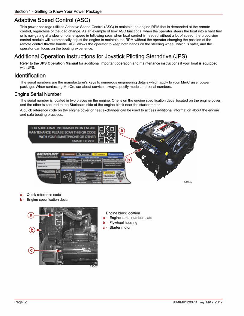
Engine Serial NumberThe serial number is located in two places on the engine. One is on the engine specification decal located on the engine cover,and the other is secured to the Starboard side of the engine block near the starter motor.A quick reference code on the engine cover or heat exchanger can be used to access additional information about the engineand safe boating practices.
a - Quick reference codeb - Engine specification decal
Engine block locationa - Engine serial number plateb - Flywheel housingc - Starter motor
a
b
54925
a
b
c
39307
Section 1 - Getting to Know Your Power Package
Page 2 90-8M0128973 eng MAY 2017
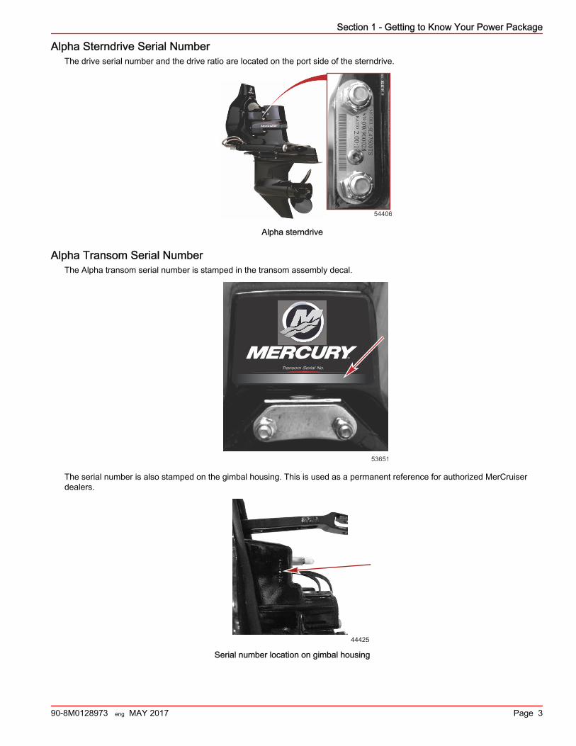
Alpha Sterndrive Serial NumberThe drive serial number and the drive ratio are located on the port side of the sterndrive.
54406
Alpha sterndrive
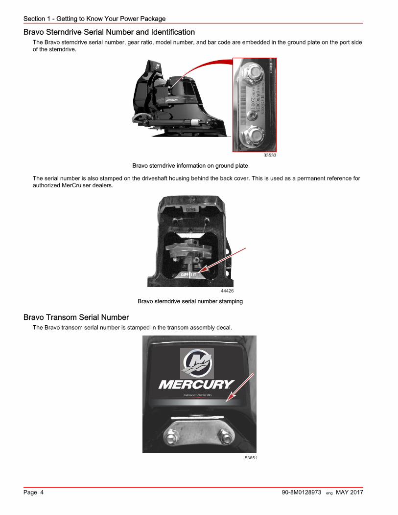
Alpha Transom Serial NumberThe Alpha transom serial number is stamped in the transom assembly decal.
Transom Serial No.
53651
The serial number is also stamped on the gimbal housing. This is used as a permanent reference for authorized MerCruiserdealers.
44425
Serial number location on gimbal housing
Section 1 - Getting to Know Your Power Package
90-8M0128973 eng MAY 2017 Page 3
Bravo Sterndrive Serial Number and IdentificationThe Bravo sterndrive serial number, gear ratio, model number, and bar code are embedded in the ground plate on the port sideof the sterndrive.
33533
Bravo sterndrive information on ground plate
The serial number is also stamped on the driveshaft housing behind the back cover. This is used as a permanent reference forauthorized MerCruiser dealers.
44426
Bravo sterndrive serial number stamping
Bravo Transom Serial NumberThe Bravo transom serial number is stamped in the transom assembly decal.
Transom Serial No.
53651
Section 1 - Getting to Know Your Power Package
Page 4 90-8M0128973 eng MAY 2017
The serial number is also stamped on the gimbal housing. This is used as a permanent reference for authorized MerCruiserdealers.
44425
Serial number location on gimbal housing
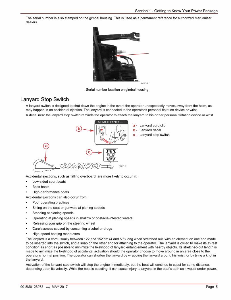
Lanyard Stop SwitchA lanyard switch is designed to shut down the engine in the event the operator unexpectedly moves away from the helm, asmay happen in an accidental ejection. The lanyard is connected to the operator's personal flotation device or wrist.A decal near the lanyard stop switch reminds the operator to attach the lanyard to his or her personal flotation device or wrist.
a - Lanyard cord clipb - Lanyard decalc - Lanyard stop switch
Accidental ejections, such as falling overboard, are more likely to occur in:• Low‑sided sport boats• Bass boats• High‑performance boatsAccidental ejections can also occur from:• Poor operating practices• Sitting on the seat or gunwale at planing speeds• Standing at planing speeds• Operating at planing speeds in shallow or obstacle‑infested waters• Releasing your grip on the steering wheel• Carelessness caused by consuming alcohol or drugs• High‑speed boating maneuversThe lanyard is a cord usually between 122 and 152 cm (4 and 5 ft) long when stretched out, with an element on one end madeto be inserted into the switch, and a snap on the other end for attaching to the operator. The lanyard is coiled to make its at‑restcondition as short as possible to minimize the likelihood of lanyard entanglement with nearby objects. Its stretched‑out length ismade to minimize the likelihood of accidental activation should the operator choose to move around in an area close to theoperator's normal position. The operator can shorten the lanyard by wrapping the lanyard around his wrist, or by tying a knot inthe lanyard.Activation of the lanyard stop switch will stop the engine immediately, but the boat will continue to coast for some distance,depending upon its velocity. While the boat is coasting, it can cause injury to anyone in the boat's path as it would under power.
ca
b
53910
OFF
RUN
ATTACH LANYARD
Section 1 - Getting to Know Your Power Package
90-8M0128973 eng MAY 2017 Page 5
Instruct all passengers on the proper starting and operating procedures should they be required to operate the boat in anemergency.
! WARNINGIf the operator falls out of the boat, stop the engine immediately to reduce the possibility of serious injury or death from beingstruck by the boat. Always properly connect the operator to the stop switch using a lanyard.
Accidental or unintended activation of the switch during normal operation is also a possibility. This could cause any, or all, ofthe following potentially hazardous situations:• Occupants could be thrown forward due to unexpected loss of forward motion, a particular concern for passengers in the
front of the boat who could be ejected over the bow and possibly struck by the propulsion or steering components.• Loss of power and directional control in heavy seas, strong current, or high winds.• Loss of control when docking.
! WARNINGAvoid serious injury or death from deceleration forces resulting from accidental or unintended stop switch activation. The boatoperator should never leave the operator's station without first disconnecting the stop switch lanyard from the operator.
Keep the Lanyard Stop Switch and Lanyard Cord in Good Operating ConditionBefore each use, ensure that the lanyard stop switch works properly. Start the engine, and then stop it by pulling the lanyardcord. If the engine does not stop, have the switch repaired before operating the boat.Before each use, inspect the lanyard cord to ensure that it is in good working condition and that there are no breaks, cuts, orwear to the cord. Check that the clips on the ends of the cord are in good condition. Replace any damaged or worn lanyardcords.
InstrumentationVesselView
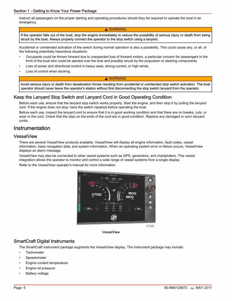
There are several VesselView products available. VesselView will display all engine information, fault codes, vesselinformation, basic navigation data, and system information. When an operating system error or failure occurs, VesselViewdisplays an alarm message.VesselView may also be connected to other vessel systems such as GPS, generators, and chartplotters. This vesselintegration allows the operator to monitor and control a wide range of vessel systems from a single display.Refer to the VesselView operator's manual for more information.
61325
VesselView
SmartCraft Digital InstrumentsThe SmartCraft instrument package augments the VesselView display. The instrument package may include:• Tachometer• Speedometer• Engine coolant temperature• Engine oil pressure• Battery voltage
Section 1 - Getting to Know Your Power Package
Page 6 90-8M0128973 eng MAY 2017
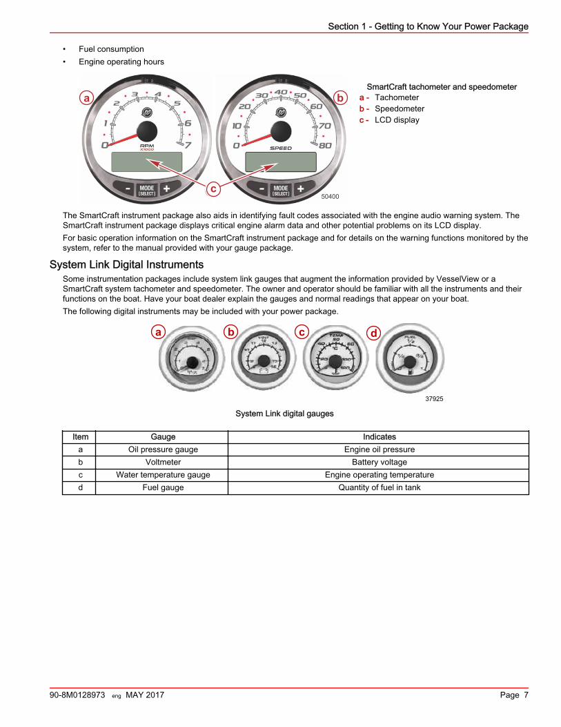
• Fuel consumption• Engine operating hours
SmartCraft tachometer and speedometera - Tachometerb - Speedometerc - LCD display
The SmartCraft instrument package also aids in identifying fault codes associated with the engine audio warning system. TheSmartCraft instrument package displays critical engine alarm data and other potential problems on its LCD display.For basic operation information on the SmartCraft instrument package and for details on the warning functions monitored by thesystem, refer to the manual provided with your gauge package.
System Link Digital InstrumentsSome instrumentation packages include system link gauges that augment the information provided by VesselView or aSmartCraft system tachometer and speedometer. The owner and operator should be familiar with all the instruments and theirfunctions on the boat. Have your boat dealer explain the gauges and normal readings that appear on your boat.The following digital instruments may be included with your power package.
a b c d
37925
System Link digital gauges
Item Gauge Indicatesa Oil pressure gauge Engine oil pressureb Voltmeter Battery voltagec Water temperature gauge Engine operating temperatured Fuel gauge Quantity of fuel in tank
a b
cc50400
Section 1 - Getting to Know Your Power Package
90-8M0128973 eng MAY 2017 Page 7
Remote Controls (Non‑DTS Models)Remote Control Features—Non‑DTS
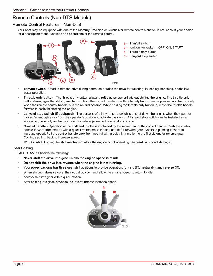
Your boat may be equipped with one of the Mercury Precision or Quicksilver remote controls shown. If not, consult your dealerfor a description of the functions and operations of the remote control.
a - Trim/tilt switchb - Ignition key switch—OFF, ON, STARTc - Throttle only buttond - Lanyard stop switch
• Trim/tilt switch ‑ Used to trim the drive during operation or raise the drive for trailering, launching, beaching, or shallowwater operation.
• Throttle only button ‑ The throttle only button allows throttle advancement without shifting the engine. The throttle onlybutton disengages the shifting mechanism from the control handle. The throttle only button can be pressed and held in onlywhen the remote control handle is in the neutral position. While holding the throttle only button in, move the throttle handleforward to assist in starting the engine.
• Lanyard stop switch (if equipped) ‑ The purpose of a lanyard stop switch is to shut down the engine when the operatormoves far enough away from the operator's position to activate the switch. A lanyard stop switch can be installed as anaccessory, generally on the dashboard or side adjacent to the operator's position.
• Control handle ‑ Operation of the shift and throttle is controlled by the movement of the control handle. Push the controlhandle forward from neutral with a quick firm motion to the first detent for forward gear. Continue pushing forward toincrease speed. Pull the control handle back from neutral with a quick firm motion to the first detent for reverse gear.Continue pulling back to increase speed.IMPORTANT: Forcing the shift mechanism while the engine is not operating can result in product damage.
Gear ShiftingIMPORTANT: Observe the following:• Never shift the drive into gear unless the engine speed is at idle.• Do not shift the drive into reverse when the engine is not running.• Your power package has three gear shift positions to provide operation: forward (F), neutral (N), and reverse (R).• When shifting, always stop at the neutral position and allow the engine speed to return to idle.• Always shift into gear with a quick motion.• After shifting into gear, advance the lever further to increase speed.
NRF
58239
aaa
b
c cc
58240d
Section 1 - Getting to Know Your Power Package
Page 8 90-8M0128973 eng MAY 2017
Remote Controls (DTS Models)Remote Controls
IMPORTANT: Your boat must be equipped with a Mercury Marine electronic remote control. Start in gear protection is providedby this control system and prevents the engine from starting when the control is actuated in forward or reverse. Refer to theMercury Precision Parts/Quicksilver Accessories Guide.The digital throttle and shift (DTS) system required to operate this engine package provides start and stop functions, throttlecontrol, shift control, start in gear protection, and emergency lanyard stop functions. The DTS system works with specializedhelm components such as a command module kit and electronic remote control. Consult your dealer for a description and/ordemonstration of your remote control.
Panel Mount Features
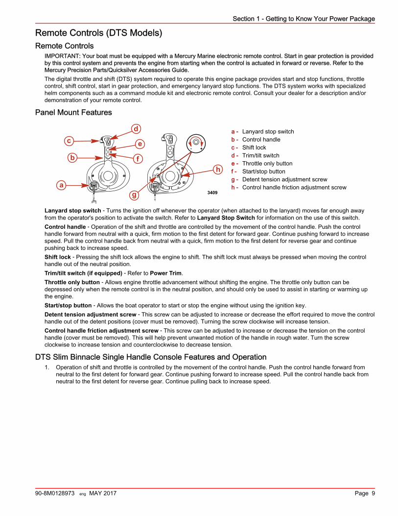
a - Lanyard stop switchb - Control handlec - Shift lockd - Trim/tilt switche - Throttle only buttonf - Start/stop buttong - Detent tension adjustment screwh - Control handle friction adjustment screw
Lanyard stop switch ‑ Turns the ignition off whenever the operator (when attached to the lanyard) moves far enough awayfrom the operator's position to activate the switch. Refer to Lanyard Stop Switch for information on the use of this switch.Control handle ‑ Operation of the shift and throttle are controlled by the movement of the control handle. Push the controlhandle forward from neutral with a quick, firm motion to the first detent for forward gear. Continue pushing forward to increasespeed. Pull the control handle back from neutral with a quick, firm motion to the first detent for reverse gear and continuepushing back to increase speed.Shift lock ‑ Pressing the shift lock allows the engine to shift. The shift lock must always be pressed when moving the controlhandle out of the neutral position.Trim/tilt switch (if equipped) ‑ Refer to Power Trim.Throttle only button ‑ Allows engine throttle advancement without shifting the engine. The throttle only button can bedepressed only when the remote control is in the neutral position, and should only be used to assist in starting or warming upthe engine.Start/stop button ‑ Allows the boat operator to start or stop the engine without using the ignition key.Detent tension adjustment screw ‑ This screw can be adjusted to increase or decrease the effort required to move the controlhandle out of the detent positions (cover must be removed). Turning the screw clockwise will increase tension.Control handle friction adjustment screw ‑ This screw can be adjusted to increase or decrease the tension on the controlhandle (cover must be removed). This will help prevent unwanted motion of the handle in rough water. Turn the screwclockwise to increase tension and counterclockwise to decrease tension.
DTS Slim Binnacle Single Handle Console Features and Operation1. Operation of shift and throttle is controlled by the movement of the control handle. Push the control handle forward from
neutral to the first detent for forward gear. Continue pushing forward to increase speed. Pull the control handle back fromneutral to the first detent for reverse gear. Continue pulling back to increase speed.
3409
+-
a
b
cd
h
e
f
g
Section 1 - Getting to Know Your Power Package
90-8M0128973 eng MAY 2017 Page 9
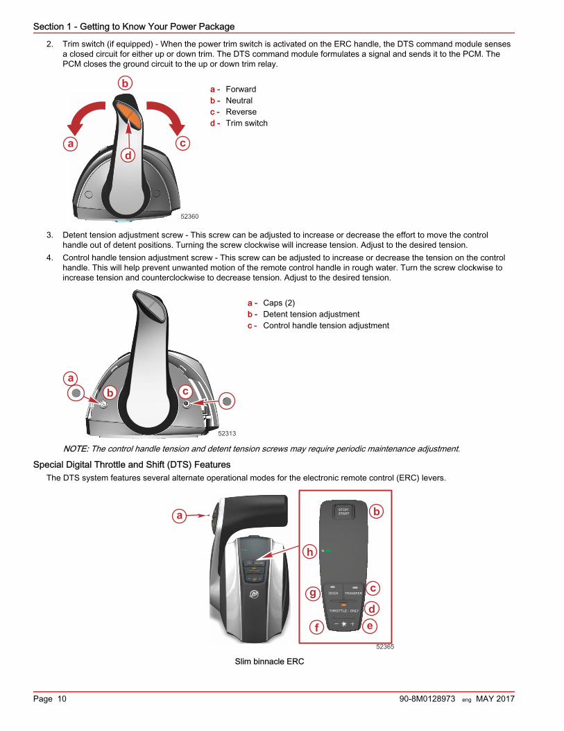
2. Trim switch (if equipped) ‑ When the power trim switch is activated on the ERC handle, the DTS command module sensesa closed circuit for either up or down trim. The DTS command module formulates a signal and sends it to the PCM. ThePCM closes the ground circuit to the up or down trim relay.
a - Forwardb - Neutralc - Reversed - Trim switch
3. Detent tension adjustment screw ‑ This screw can be adjusted to increase or decrease the effort to move the controlhandle out of detent positions. Turning the screw clockwise will increase tension. Adjust to the desired tension.
4. Control handle tension adjustment screw ‑ This screw can be adjusted to increase or decrease the tension on the controlhandle. This will help prevent unwanted motion of the remote control handle in rough water. Turn the screw clockwise toincrease tension and counterclockwise to decrease tension. Adjust to the desired tension.
a - Caps (2)b - Detent tension adjustmentc - Control handle tension adjustment
NOTE: The control handle tension and detent tension screws may require periodic maintenance adjustment.
Special Digital Throttle and Shift (DTS) FeaturesThe DTS system features several alternate operational modes for the electronic remote control (ERC) levers.
aSTOP/START
THROTTLE - ONLY
DOCK TRANSFER
N
b
c
def
g
52365
h
Slim binnacle ERC
a
b
cd
52360
ab c
52313
Section 1 - Getting to Know Your Power Package
Page 10 90-8M0128973 eng MAY 2017
Item Control Function
a Trim control(handle)
Raises and lowers the sterndrive for best efficiency, or for conditions such as shallow water,trailering, etc.
b Stop/Start Allows the operator to start or stop the engine without the use of the key switch. The key switchmust be in the run position for the start/stop switch to function.
c Transfer Allows boat control to be transferred to a different helm.
d Throttle‑only Allows the boat operator to increase engine RPM for warm‑up without shifting the transmissioninto gear.
e + Increases brightness settings for the CAN pad, VesselView, and SmartCraft gauges.f – Decreases brightness settings for the CAN pad, VesselView, and SmartCraft gauges.
g Dock Reduces control lever operation throttle capacity to approximately 50% of normal control leverthrottle demand.
h Neutral light Illuminates when the drive is in the neutral gear position. The lights flash when the engine is inthrottle only mode.
Dual‑Handle Electronic Remote Control (ERC)—Operation and AdjustmentOperation
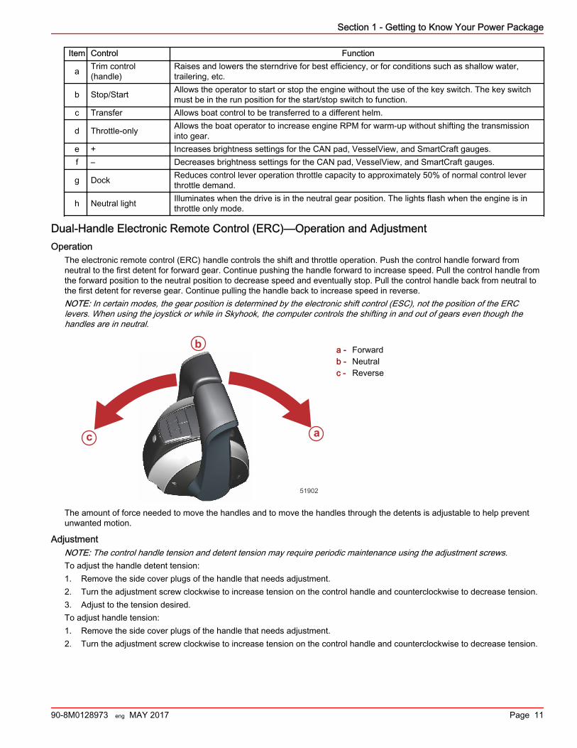
The electronic remote control (ERC) handle controls the shift and throttle operation. Push the control handle forward fromneutral to the first detent for forward gear. Continue pushing the handle forward to increase speed. Pull the control handle fromthe forward position to the neutral position to decrease speed and eventually stop. Pull the control handle back from neutral tothe first detent for reverse gear. Continue pulling the handle back to increase speed in reverse.NOTE: In certain modes, the gear position is determined by the electronic shift control (ESC), not the position of the ERClevers. When using the joystick or while in Skyhook, the computer controls the shifting in and out of gears even though thehandles are in neutral.
a - Forwardb - Neutralc - Reverse
The amount of force needed to move the handles and to move the handles through the detents is adjustable to help preventunwanted motion.
AdjustmentNOTE: The control handle tension and detent tension may require periodic maintenance using the adjustment screws.To adjust the handle detent tension:1. Remove the side cover plugs of the handle that needs adjustment.2. Turn the adjustment screw clockwise to increase tension on the control handle and counterclockwise to decrease tension.3. Adjust to the tension desired.To adjust handle tension:1. Remove the side cover plugs of the handle that needs adjustment.2. Turn the adjustment screw clockwise to increase tension on the control handle and counterclockwise to decrease tension.
a
b
c
51902
Section 1 - Getting to Know Your Power Package
90-8M0128973 eng MAY 2017 Page 11
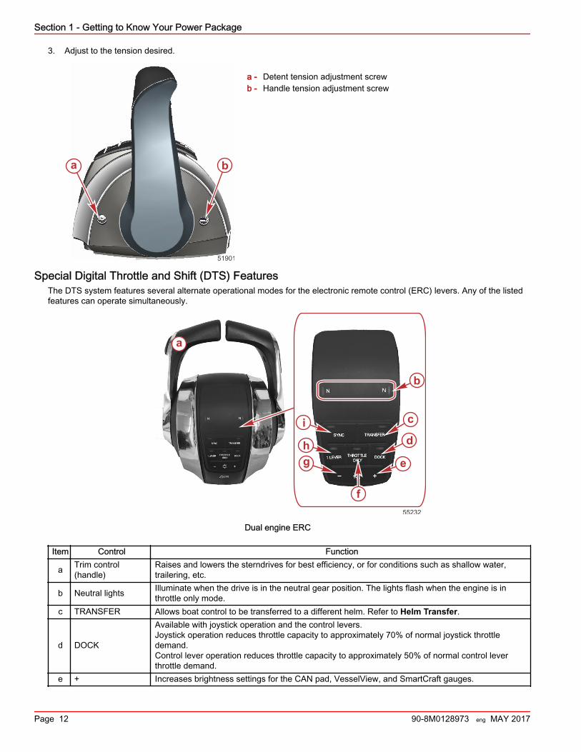
3. Adjust to the tension desired.
a - Detent tension adjustment screwb - Handle tension adjustment screw
Special Digital Throttle and Shift (DTS) FeaturesThe DTS system features several alternate operational modes for the electronic remote control (ERC) levers. Any of the listedfeatures can operate simultaneously.
b
c
d
e
f
gh
i
55232
a
Dual engine ERC
Item Control Function
a Trim control(handle)
Raises and lowers the sterndrives for best efficiency, or for conditions such as shallow water,trailering, etc.
b Neutral lights Illuminate when the drive is in the neutral gear position. The lights flash when the engine is inthrottle only mode.
c TRANSFER Allows boat control to be transferred to a different helm. Refer to Helm Transfer.
d DOCK
Available with joystick operation and the control levers.Joystick operation reduces throttle capacity to approximately 70% of normal joystick throttledemand.Control lever operation reduces throttle capacity to approximately 50% of normal control leverthrottle demand.
e + Increases brightness settings for the CAN pad, VesselView, and SmartCraft gauges.
a b
51901
Section 1 - Getting to Know Your Power Package
Page 12 90-8M0128973 eng MAY 2017
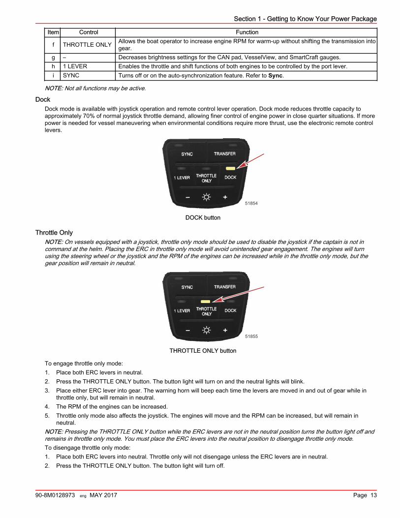
Item Control Function
f THROTTLE ONLY Allows the boat operator to increase engine RPM for warm‑up without shifting the transmission intogear.
g – Decreases brightness settings for the CAN pad, VesselView, and SmartCraft gauges.h 1 LEVER Enables the throttle and shift functions of both engines to be controlled by the port lever.i SYNC Turns off or on the auto‑synchronization feature. Refer to Sync.
NOTE: Not all functions may be active.
DockDock mode is available with joystick operation and remote control lever operation. Dock mode reduces throttle capacity toapproximately 70% of normal joystick throttle demand, allowing finer control of engine power in close quarter situations. If morepower is needed for vessel maneuvering when environmental conditions require more thrust, use the electronic remote controllevers.
51854
DOCK button
Throttle OnlyNOTE: On vessels equipped with a joystick, throttle only mode should be used to disable the joystick if the captain is not incommand at the helm. Placing the ERC in throttle only mode will avoid unintended gear engagement. The engines will turnusing the steering wheel or the joystick and the RPM of the engines can be increased while in the throttle only mode, but thegear position will remain in neutral.
51855
THROTTLE ONLY button
To engage throttle only mode:1. Place both ERC levers in neutral.2. Press the THROTTLE ONLY button. The button light will turn on and the neutral lights will blink.3. Place either ERC lever into gear. The warning horn will beep each time the levers are moved in and out of gear while in
throttle only, but will remain in neutral.4. The RPM of the engines can be increased.5. Throttle only mode also affects the joystick. The engines will move and the RPM can be increased, but will remain in
neutral.NOTE: Pressing the THROTTLE ONLY button while the ERC levers are not in the neutral position turns the button light off andremains in throttle only mode. You must place the ERC levers into the neutral position to disengage throttle only mode.To disengage throttle only mode:1. Place both ERC levers into neutral. Throttle only will not disengage unless the ERC levers are in neutral.2. Press the THROTTLE ONLY button. The button light will turn off.
Section 1 - Getting to Know Your Power Package
90-8M0128973 eng MAY 2017 Page 13
3. The neutral lights stop flashing and remain illuminated. The joystick can now be used.
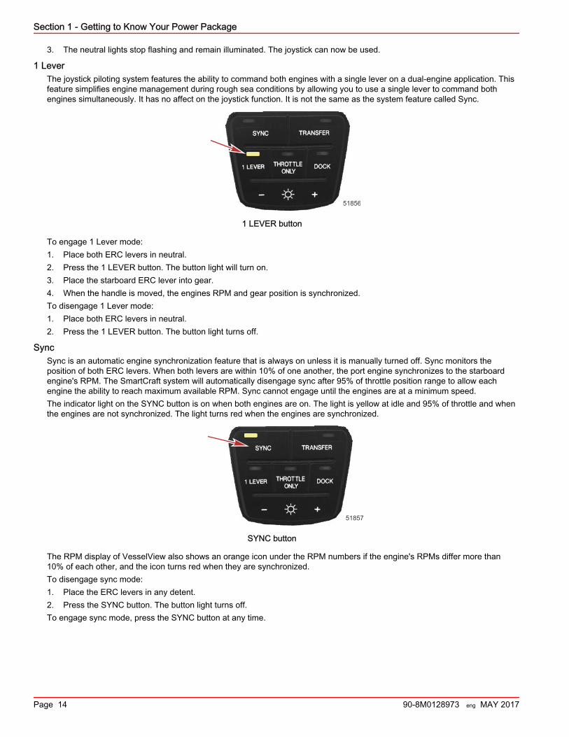
1 LeverThe joystick piloting system features the ability to command both engines with a single lever on a dual‑engine application. Thisfeature simplifies engine management during rough sea conditions by allowing you to use a single lever to command bothengines simultaneously. It has no affect on the joystick function. It is not the same as the system feature called Sync.
51856
1 LEVER button
To engage 1 Lever mode:1. Place both ERC levers in neutral.2. Press the 1 LEVER button. The button light will turn on.3. Place the starboard ERC lever into gear.4. When the handle is moved, the engines RPM and gear position is synchronized.To disengage 1 Lever mode:1. Place both ERC levers in neutral.2. Press the 1 LEVER button. The button light turns off.
SyncSync is an automatic engine synchronization feature that is always on unless it is manually turned off. Sync monitors theposition of both ERC levers. When both levers are within 10% of one another, the port engine synchronizes to the starboardengine's RPM. The SmartCraft system will automatically disengage sync after 95% of throttle position range to allow eachengine the ability to reach maximum available RPM. Sync cannot engage until the engines are at a minimum speed.The indicator light on the SYNC button is on when both engines are on. The light is yellow at idle and 95% of throttle and whenthe engines are not synchronized. The light turns red when the engines are synchronized.
51857
SYNC button
The RPM display of VesselView also shows an orange icon under the RPM numbers if the engine's RPMs differ more than10% of each other, and the icon turns red when they are synchronized.To disengage sync mode:1. Place the ERC levers in any detent.2. Press the SYNC button. The button light turns off.To engage sync mode, press the SYNC button at any time.
Section 1 - Getting to Know Your Power Package
Page 14 90-8M0128973 eng MAY 2017
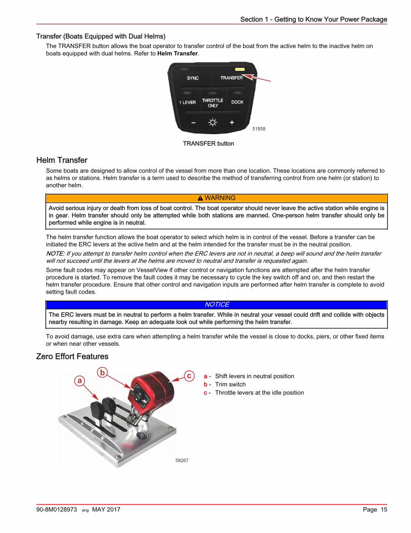
Transfer (Boats Equipped with Dual Helms)The TRANSFER button allows the boat operator to transfer control of the boat from the active helm to the inactive helm onboats equipped with dual helms. Refer to Helm Transfer.
51858
TRANSFER button
Helm TransferSome boats are designed to allow control of the vessel from more than one location. These locations are commonly referred toas helms or stations. Helm transfer is a term used to describe the method of transferring control from one helm (or station) toanother helm.
! WARNINGAvoid serious injury or death from loss of boat control. The boat operator should never leave the active station while engine isin gear. Helm transfer should only be attempted while both stations are manned. One‑person helm transfer should only beperformed while engine is in neutral.
The helm transfer function allows the boat operator to select which helm is in control of the vessel. Before a transfer can beinitiated the ERC levers at the active helm and at the helm intended for the transfer must be in the neutral position.NOTE: If you attempt to transfer helm control when the ERC levers are not in neutral, a beep will sound and the helm transferwill not succeed until the levers at the helms are moved to neutral and transfer is requested again.Some fault codes may appear on VesselView if other control or navigation functions are attempted after the helm transferprocedure is started. To remove the fault codes it may be necessary to cycle the key switch off and on, and then restart thehelm transfer procedure. Ensure that other control and navigation inputs are performed after helm transfer is complete to avoidsetting fault codes.
NOTICEThe ERC levers must be in neutral to perform a helm transfer. While in neutral your vessel could drift and collide with objectsnearby resulting in damage. Keep an adequate look out while performing the helm transfer.
To avoid damage, use extra care when attempting a helm transfer while the vessel is close to docks, piers, or other fixed itemsor when near other vessels.
Zero Effort Features
a - Shift levers in neutral positionb - Trim switchc - Throttle levers at the idle position
ba c
58267
Section 1 - Getting to Know Your Power Package
90-8M0128973 eng MAY 2017 Page 15
Shift lever ‑ Shift functions are controlled by the movement of the shift lever. Shift into reverse by moving the shift lever to itsaft position. Shift into neutral by moving the shift lever to its center position. Shift into forward by moving the shift lever to itsforward position.Throttle lever ‑ Throttle functions are controlled by the movement of the throttle lever. Increase the RPM by moving the throttlelever forward. Achieve wide‑open throttle (WOT) by placing the throttle lever in its full forward position. Decrease RPM bymoving the throttle lever back. Achieve minimum RPM (idle) by placing the throttle lever in its full aft position.Trim/tilt switch ‑ Refer to Power Trim.
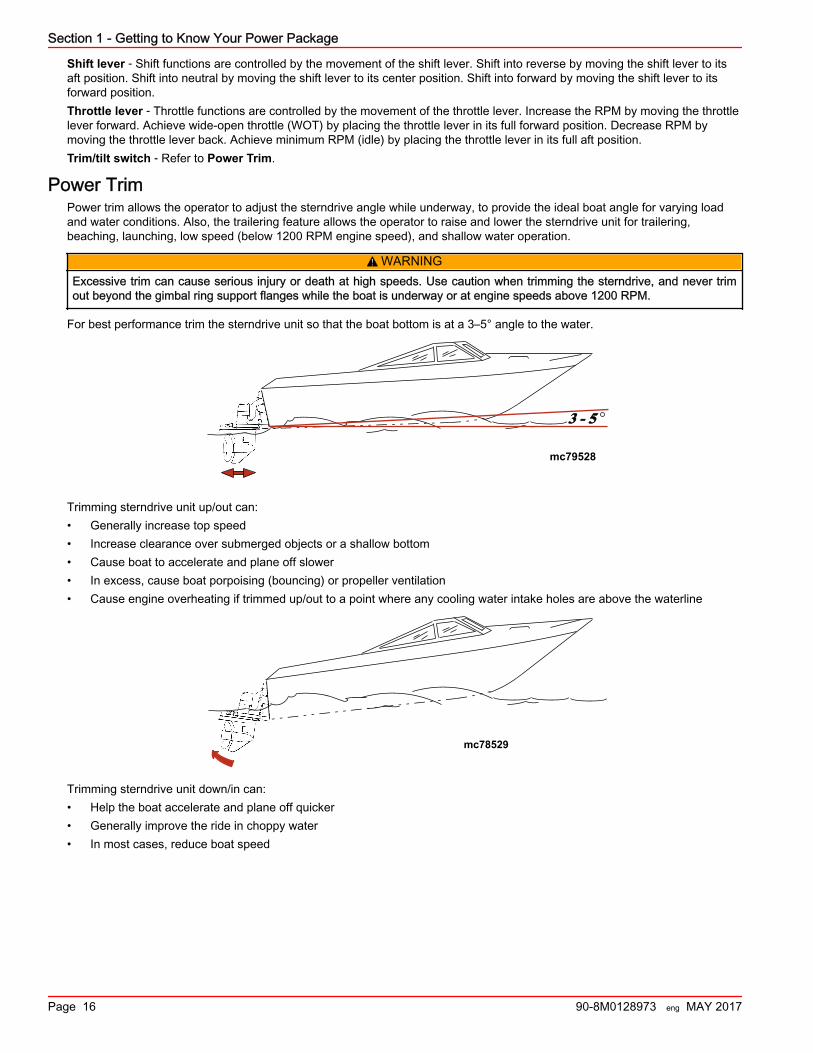
Power TrimPower trim allows the operator to adjust the sterndrive angle while underway, to provide the ideal boat angle for varying loadand water conditions. Also, the trailering feature allows the operator to raise and lower the sterndrive unit for trailering,beaching, launching, low speed (below 1200 RPM engine speed), and shallow water operation.
! WARNINGExcessive trim can cause serious injury or death at high speeds. Use caution when trimming the sterndrive, and never trimout beyond the gimbal ring support flanges while the boat is underway or at engine speeds above 1200 RPM.
For best performance trim the sterndrive unit so that the boat bottom is at a 3–5° angle to the water.
3 - 5
mc79528
Trimming sterndrive unit up/out can:• Generally increase top speed• Increase clearance over submerged objects or a shallow bottom• Cause boat to accelerate and plane off slower• In excess, cause boat porpoising (bouncing) or propeller ventilation• Cause engine overheating if trimmed up/out to a point where any cooling water intake holes are above the waterline
mc78529
Trimming sterndrive unit down/in can:• Help the boat accelerate and plane off quicker• Generally improve the ride in choppy water• In most cases, reduce boat speed
Section 1 - Getting to Know Your Power Package
Page 16 90-8M0128973 eng MAY 2017
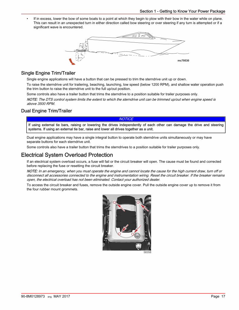
• If in excess, lower the bow of some boats to a point at which they begin to plow with their bow in the water while on plane.This can result in an unexpected turn in either direction called bow steering or over steering if any turn is attempted or if asignificant wave is encountered.
mc79530
Single Engine Trim/TrailerSingle engine applications will have a button that can be pressed to trim the sterndrive unit up or down.To raise the sterndrive unit for trailering, beaching, launching, low speed (below 1200 RPM), and shallow water operation pushthe trim button to raise the sterndrive unit to the full up/out position.Some controls also have a trailer button that trims the sterndrive to a position suitable for trailer purposes only.NOTE: The DTS control system limits the extent to which the sterndrive unit can be trimmed up/out when engine speed isabove 3500 RPM.
Dual Engine Trim/TrailerNOTICE
If using external tie bars, raising or lowering the drives independently of each other can damage the drive and steeringsystems. If using an external tie bar, raise and lower all drives together as a unit.
Dual engine applications may have a single integral button to operate both sterndrive units simultaneously or may haveseparate buttons for each sterndrive unit.Some controls also have a trailer button that trims the sterndrives to a position suitable for trailer purposes only.
Electrical System Overload ProtectionIf an electrical system overload occurs, a fuse will fail or the circuit breaker will open. The cause must be found and correctedbefore replacing the fuse or resetting the circuit breaker.NOTE: In an emergency, when you must operate the engine and cannot locate the cause for the high current draw, turn off ordisconnect all accessories connected to the engine and instrumentation wiring. Reset the circuit breaker. If the breaker remainsopen, the electrical overload has not been eliminated. Contact your authorized dealer.To access the circuit breaker and fuses, remove the outside engine cover. Pull the outside engine cover up to remove it fromthe four rubber mount grommets.
58358
Section 1 - Getting to Know Your Power Package
90-8M0128973 eng MAY 2017 Page 17
The circuit breaker provides protection for the engine wiring harness and the instrumentation power lead.
55033
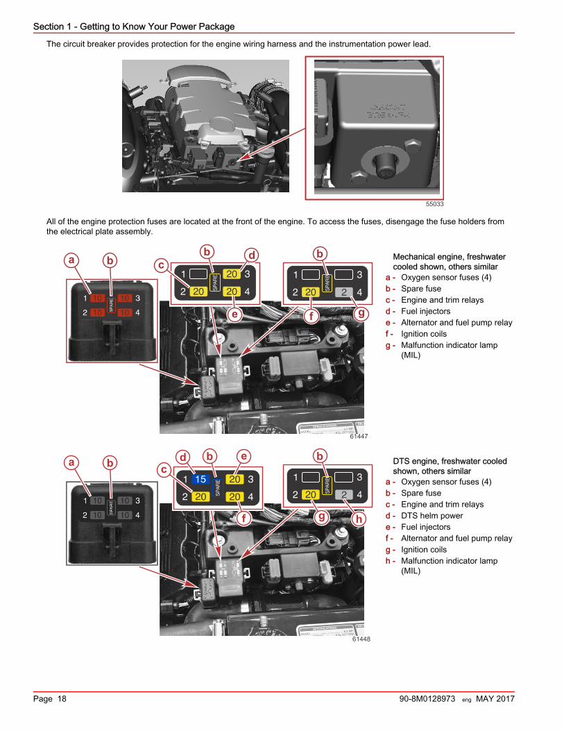
All of the engine protection fuses are located at the front of the engine. To access the fuses, disengage the fuse holders fromthe electrical plate assembly.
Mechanical engine, freshwatercooled shown, others similar
a - Oxygen sensor fuses (4)b - Spare fusec - Engine and trim relaysd - Fuel injectorse - Alternator and fuel pump relayf - Ignition coilsg - Malfunction indicator lamp
(MIL)
DTS engine, freshwater cooledshown, others similar
a - Oxygen sensor fuses (4)b - Spare fusec - Engine and trim relaysd - DTS helm powere - Fuel injectorsf - Alternator and fuel pump relayg - Ignition coilsh - Malfunction indicator lamp
(MIL)
a b cb d
e f
b
g
61447
a b cbd e
f
b
g h
61448
Section 1 - Getting to Know Your Power Package
Page 18 90-8M0128973 eng MAY 2017
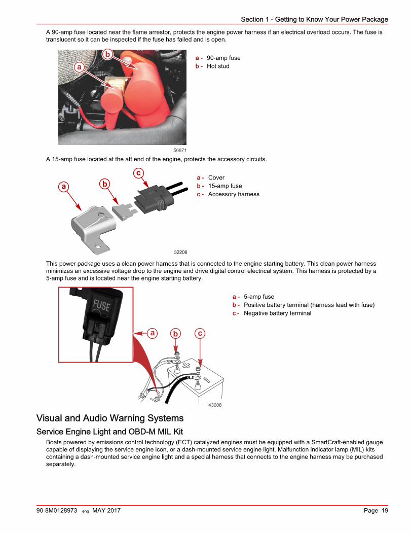
A 90‑amp fuse located near the flame arrestor, protects the engine power harness if an electrical overload occurs. The fuse istranslucent so it can be inspected if the fuse has failed and is open.
a - 90‑amp fuseb - Hot stud
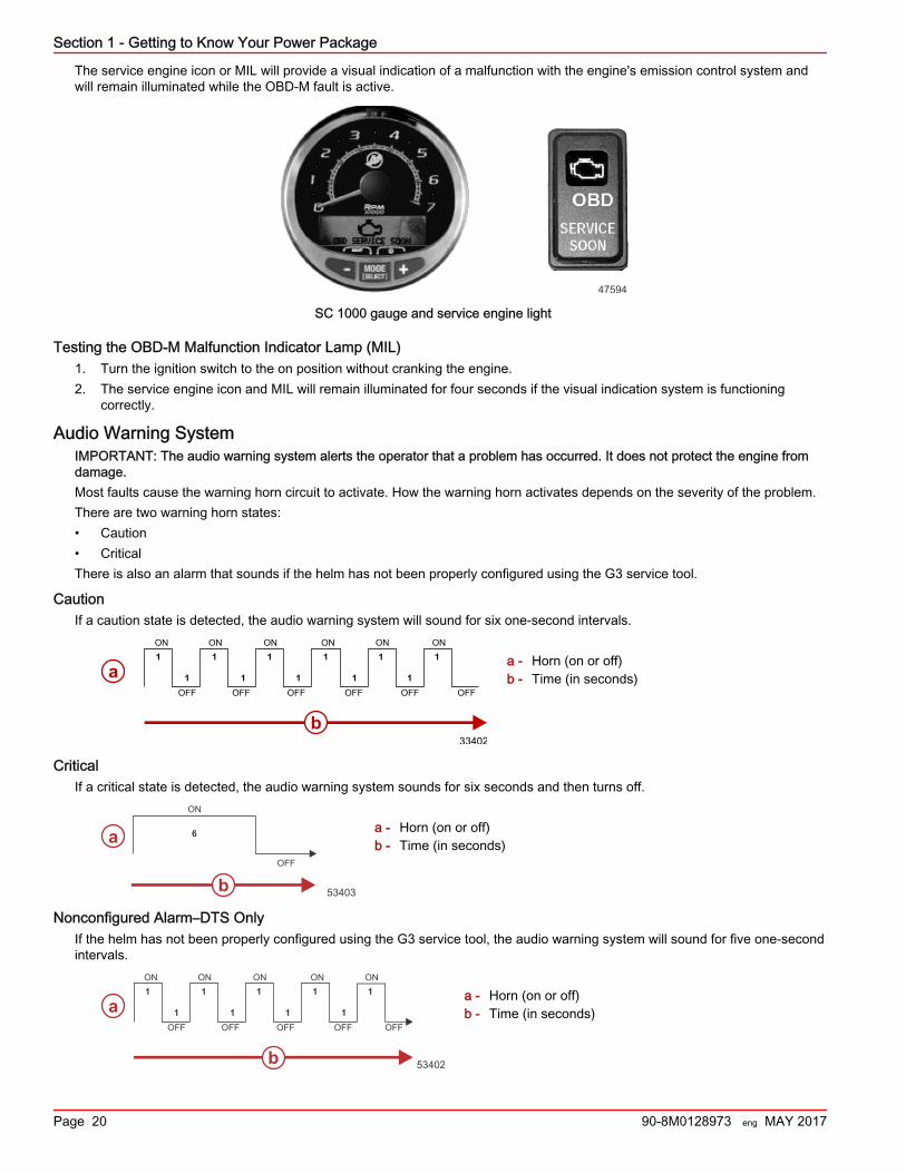
A 15‑amp fuse located at the aft end of the engine, protects the accessory circuits.
a - Coverb - 15‑amp fusec - Accessory harness
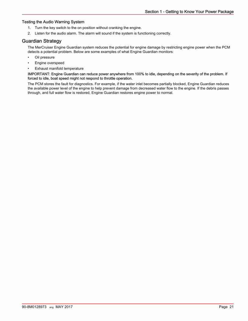
This power package uses a clean power harness that is connected to the engine starting battery. This clean power harnessminimizes an excessive voltage drop to the engine and drive digital control electrical system. This harness is protected by a5‑amp fuse and is located near the engine starting battery.
a - 5‑amp fuseb - Positive battery terminal (harness lead with fuse)c - Negative battery terminal
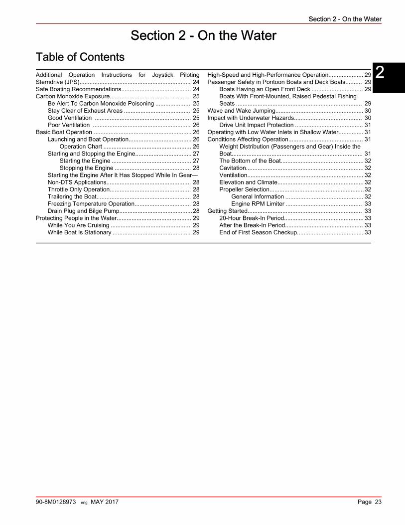
Visual and Audio Warning SystemsService Engine Light and OBD‑M MIL Kit
Boats powered by emissions control technology (ECT) catalyzed engines must be equipped with a SmartCraft‑enabled gaugecapable of displaying the service engine icon, or a dash‑mounted service engine light. Malfunction indicator lamp (MIL) kitscontaining a dash‑mounted service engine light and a special harness that connects to the engine harness may be purchasedseparately.
ab
56871
a bc
32206
43608
a b c
Section 1 - Getting to Know Your Power Package
90-8M0128973 eng MAY 2017 Page 19
The service engine icon or MIL will provide a visual indication of a malfunction with the engine's emission control system andwill remain illuminated while the OBD‑M fault is active.
47594
SC 1000 gauge and service engine light
Testing the OBD-M Malfunction Indicator Lamp (MIL)1. Turn the ignition switch to the on position without cranking the engine.2. The service engine icon and MIL will remain illuminated for four seconds if the visual indication system is functioning
correctly.
Audio Warning SystemIMPORTANT: The audio warning system alerts the operator that a problem has occurred. It does not protect the engine fromdamage.Most faults cause the warning horn circuit to activate. How the warning horn activates depends on the severity of the problem.There are two warning horn states:• Caution• CriticalThere is also an alarm that sounds if the helm has not been properly configured using the G3 service tool.
CautionIf a caution state is detected, the audio warning system will sound for six one‑second intervals.
a - Horn (on or off)b - Time (in seconds)
CriticalIf a critical state is detected, the audio warning system sounds for six seconds and then turns off.
a - Horn (on or off)b - Time (in seconds)
Nonconfigured Alarm–DTS OnlyIf the helm has not been properly configured using the G3 service tool, the audio warning system will sound for five one‑secondintervals.
a - Horn (on or off)b - Time (in seconds)
ON ON
OFF
ON
OFF
ON
OFF
ON
OFF
ON
OFF
1
1
1
1
1
1
1
1
1
1
1
OFF
33402
a
b
53403
a
b
ON
6
OFF
ON ON
OFF
ON
OFF
ON
OFF
ON
OFF
1
1
1
1
1
1
1
1
1
OFF
53402
a
b
Section 1 - Getting to Know Your Power Package
Page 20 90-8M0128973 eng MAY 2017
Testing the Audio Warning System1. Turn the key switch to the on position without cranking the engine.2. Listen for the audio alarm. The alarm will sound if the system is functioning correctly.
Guardian StrategyThe MerCruiser Engine Guardian system reduces the potential for engine damage by restricting engine power when the PCMdetects a potential problem. Below are some examples of what Engine Guardian monitors:• Oil pressure• Engine overspeed• Exhaust manifold temperatureIMPORTANT: Engine Guardian can reduce power anywhere from 100% to idle, depending on the severity of the problem. Ifforced to idle, boat speed might not respond to throttle operation.The PCM stores the fault for diagnostics. For example, if the water inlet becomes partially blocked, Engine Guardian reducesthe available power level of the engine to help prevent damage from decreased water flow to the engine. If the debris passesthrough, and full water flow is restored, Engine Guardian restores engine power to normal.
Section 1 - Getting to Know Your Power Package
90-8M0128973 eng MAY 2017 Page 21

Section 1 - Getting to Know Your Power Package
Notes:
Page 22 90-8M0128973 eng MAY 2017
Section 2 - On the WaterTable of ContentsAdditional Operation Instructions for Joystick PilotingSterndrive (JPS)................................................................... 24Safe Boating Recommendations.......................................... 24Carbon Monoxide Exposure................................................. 25
Be Alert To Carbon Monoxide Poisoning ..................... 25Stay Clear of Exhaust Areas ........................................ 25Good Ventilation .......................................................... 25Poor Ventilation ........................................................... 26
Basic Boat Operation ........................................................... 26Launching and Boat Operation...................................... 26
Operation Chart ..................................................... 26Starting and Stopping the Engine.................................. 27
Starting the Engine ................................................ 27Stopping the Engine .............................................. 28
Starting the Engine After It Has Stopped While In Gear—Non‑DTS Applications................................................... 28Throttle Only Operation................................................. 28Trailering the Boat......................................................... 28Freezing Temperature Operation.................................. 28Drain Plug and Bilge Pump............................................28
Protecting People in the Water............................................. 29While You Are Cruising ................................................ 29While Boat Is Stationary ............................................... 29
High‑Speed and High‑Performance Operation..................... 29Passenger Safety in Pontoon Boats and Deck Boats.......... 29
Boats Having an Open Front Deck ............................... 29Boats With Front‑Mounted, Raised Pedestal FishingSeats ............................................................................ 29
Wave and Wake Jumping..................................................... 30Impact with Underwater Hazards......................................... 30
Drive Unit Impact Protection ......................................... 31Operating with Low Water Inlets in Shallow Water............... 31Conditions Affecting Operation............................................. 31
Weight Distribution (Passengers and Gear) Inside theBoat............................................................................... 31The Bottom of the Boat.................................................. 32Cavitation....................................................................... 32Ventilation...................................................................... 32Elevation and Climate.................................................... 32Propeller Selection.........................................................32
General Information ............................................... 32Engine RPM Limiter .............................................. 33
Getting Started..................................................................... 3320‑Hour Break‑In Period................................................ 33After the Break‑In Period............................................... 33End of First Season Checkup........................................ 33
2
Section 2 - On the Water
90-8M0128973 eng MAY 2017 Page 23
Additional Operation Instructions for Joystick Piloting Sterndrive (JPS)Refer to the JPS Operation Manual for additional important operation and maintenance instructions if your boat is equippedwith JPS.
Safe Boating RecommendationsTo safely enjoy the waterways, familiarize yourself with local and all other governmental boating regulations and restrictionsand consider the following suggestions.Know and obey all nautical rules and laws of the waterways.• We recommend that all powerboat operators complete a boating safety course. In the U.S., the U.S. Coast Guard Auxiliary,
the Power Squadron, the Red Cross, and your state or provincial boating law enforcement agency provide courses. Formore information in the U.S., call the Boat U.S. Foundation at 1‑800‑336‑BOAT (2628).
Perform safety checks and required maintenance.• Follow a regular schedule and ensure that all repairs are properly made.Check safety equipment onboard.• Here are some suggestions of the types of safety equipment to carry when boating:
Approved fire extinguishers
Signal devices: flashlight, rockets or flares, flag, and whistle or horn
Tools necessary for minor repairs
Anchor and extra anchor line
Manual bilge pump and extra drain plugs
Drinking water
Radio
Paddle or oar
Spare propeller, thrust hubs, and an appropriate wrench
First aid kit and instructions
Waterproof storage containers
Spare operating equipment, batteries, bulbs, and fuses
Compass and map or chart of the area
Personal flotation device (one per person onboard)
Watch for signs of weather change and avoid foul weather and rough‑sea boating.Tell someone where you are going and when you expect to return.Passenger boarding.• Stop the engine whenever passengers are boarding, unloading, or are near the back (stern) of the boat. Shifting the drive
unit into neutral is not sufficient.Use personal flotation devices.• Federal law requires that there be a U.S. Coast Guard‑approved life jacket (personal flotation device), correctly sized and
readily accessible for every person onboard, plus a throwable cushion or ring. We strongly advise that everyone wear a lifejacket at all times while in the boat.
Prepare other boat operators.• Instruct at least one person onboard in the basics of starting and operating the engine and boat handling in case the driver
becomes disabled or falls overboard.Do not overload your boat.• Most boats are rated and certified for maximum load (weight) capacities (refer to your boat's capacity plate). Know your
boat's operating and loading limitations. Know if your boat will float if it is full of water. When in doubt, contact yourauthorized Mercury Marine dealer or the boat manufacturer.
Ensure that everyone in the boat is properly seated.• Do not allow anyone to sit or ride on any part of the boat that was not intended for such use. This includes the backs of
seats, gunwales, transom, bow, decks, raised fishing seats, and any rotating fishing seat. Passengers should not sit or rideanywhere that sudden unexpected acceleration, sudden stopping, unexpected loss of boat control, or sudden boatmovement could cause a person to be thrown overboard or into the boat. Ensure that all passengers have a proper seatand are in it before any boat movement.
Section 2 - On the Water
Page 24 90-8M0128973 eng MAY 2017
Never operate a boat while under the influence of alcohol or drugs. It is the law.• Alcohol or drugs can impair your judgment and greatly reduce your ability to react quickly.Know your boating area and avoid hazardous locations.Be alert.• The operator of the boat is responsible by law to maintain a proper lookout by sight and hearing. The operator must have
an unobstructed view particularly to the front. No passengers, load, or fishing seats should block the operator's view whenthe boat is above idle or planing transition speed. Watch out for others, the water, and your wake.
Never drive your boat directly behind a water‑skier.• Your boat traveling at 40 km/h (25 mph) will overtake a fallen skier who is 61 m (200 ft) in front of you in five seconds.Watch fallen skiers.• When using your boat for waterskiing or similar activities, always keep a fallen or down skier on the operator's side of the
boat while returning to attend to the skier. The operator should always have the down skier in sight and never back up tothe skier or anyone in the water.
Report accidents.• Boat operators are required by law to file a boating accident report with their state boating law enforcement agency when
their boat is involved in certain boating accidents. A boating accident must be reported if 1) there is loss of life or probableloss of life, 2) there is personal injury requiring medical treatment beyond first aid, 3) there is damage to boats or otherproperty where the damage value exceeds $500.00, or 4) there is complete loss of the boat. Seek further assistance fromlocal law enforcement.
Carbon Monoxide ExposureBe Alert To Carbon Monoxide Poisoning
Carbon monoxide (CO) is a deadly gas that is present in the exhaust fumes of all internal combustion engines, including theengines that propel boats, and the generators that power boat accessories. By itself, CO is odorless, colorless, and tasteless,but if you can smell or taste engine exhaust, you are inhaling CO.Early symptoms of carbon monoxide poisoning, which are similar to the symptoms of seasickness and intoxication, includeheadache, dizziness, drowsiness, and nausea.
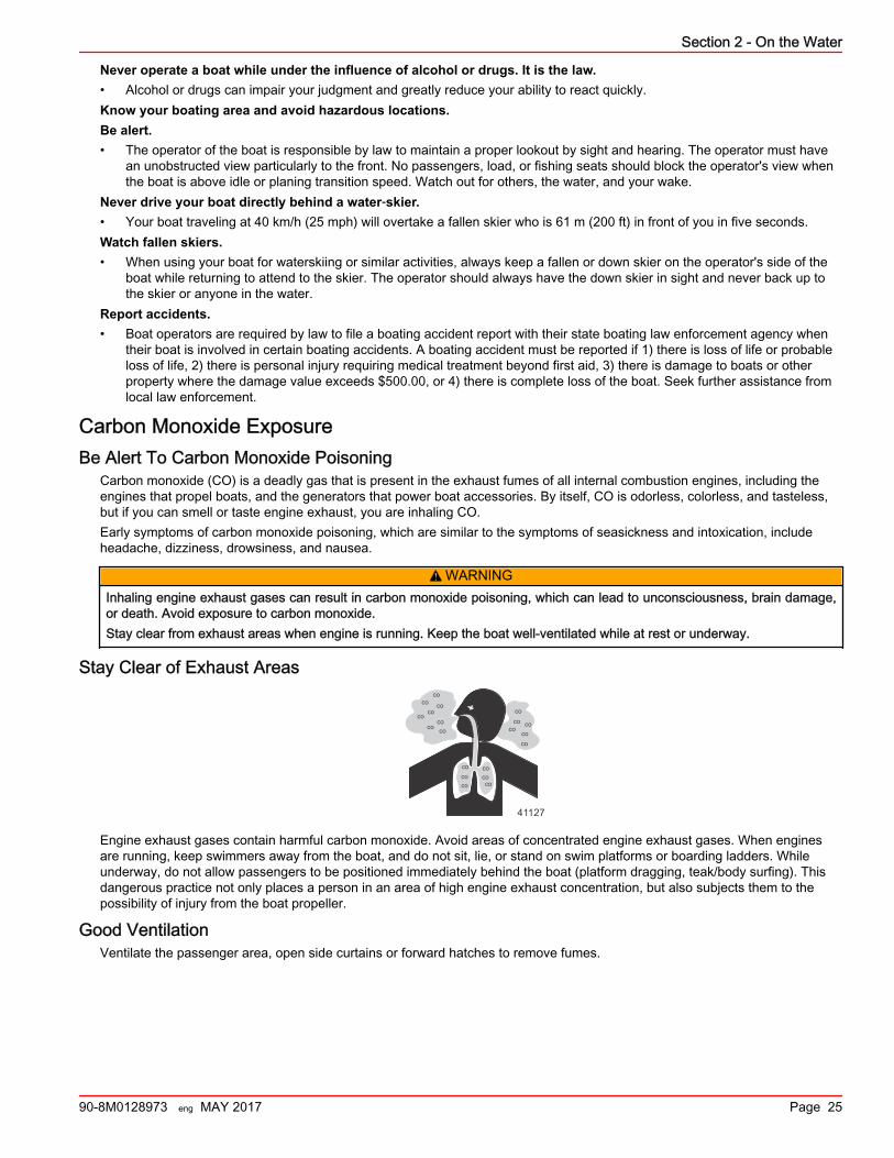
! WARNINGInhaling engine exhaust gases can result in carbon monoxide poisoning, which can lead to unconsciousness, brain damage,or death. Avoid exposure to carbon monoxide.Stay clear from exhaust areas when engine is running. Keep the boat well‑ventilated while at rest or underway.
Stay Clear of Exhaust Areas
41127
co
cococo
coco
coco
coco
coco
coco
co
co
co
coco
co
Engine exhaust gases contain harmful carbon monoxide. Avoid areas of concentrated engine exhaust gases. When enginesare running, keep swimmers away from the boat, and do not sit, lie, or stand on swim platforms or boarding ladders. Whileunderway, do not allow passengers to be positioned immediately behind the boat (platform dragging, teak/body surfing). Thisdangerous practice not only places a person in an area of high engine exhaust concentration, but also subjects them to thepossibility of injury from the boat propeller.
Good VentilationVentilate the passenger area, open side curtains or forward hatches to remove fumes.
Section 2 - On the Water
90-8M0128973 eng MAY 2017 Page 25
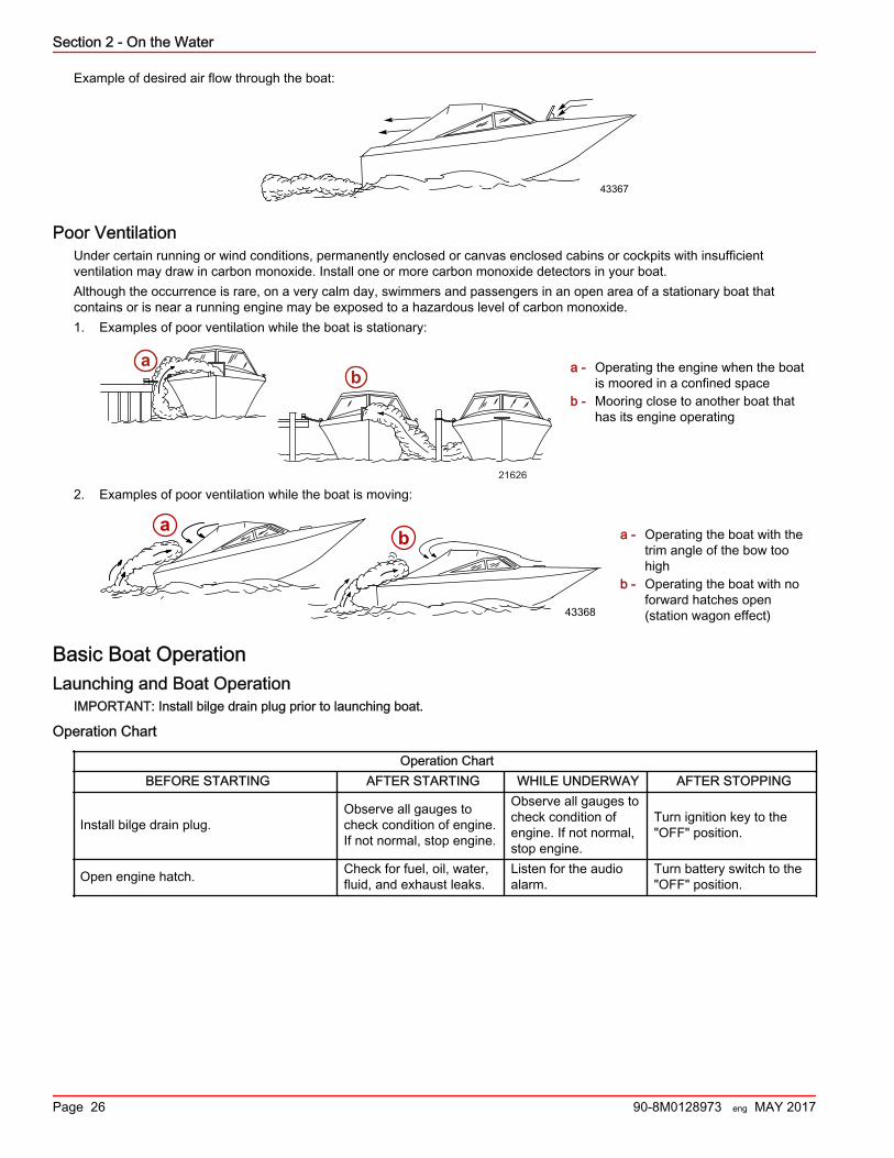
Example of desired air flow through the boat:
43367
Poor VentilationUnder certain running or wind conditions, permanently enclosed or canvas enclosed cabins or cockpits with insufficientventilation may draw in carbon monoxide. Install one or more carbon monoxide detectors in your boat.Although the occurrence is rare, on a very calm day, swimmers and passengers in an open area of a stationary boat thatcontains or is near a running engine may be exposed to a hazardous level of carbon monoxide.1. Examples of poor ventilation while the boat is stationary:
a - Operating the engine when the boatis moored in a confined space
b - Mooring close to another boat thathas its engine operating
2. Examples of poor ventilation while the boat is moving:
a - Operating the boat with thetrim angle of the bow toohigh
b - Operating the boat with noforward hatches open(station wagon effect)
Basic Boat OperationLaunching and Boat Operation
IMPORTANT: Install bilge drain plug prior to launching boat.
Operation Chart
Operation ChartBEFORE STARTING AFTER STARTING WHILE UNDERWAY AFTER STOPPING
Install bilge drain plug.Observe all gauges tocheck condition of engine.If not normal, stop engine.
Observe all gauges tocheck condition ofengine. If not normal,stop engine.
Turn ignition key to the"OFF" position.
Open engine hatch. Check for fuel, oil, water,fluid, and exhaust leaks.
Listen for the audioalarm.
Turn battery switch to the"OFF" position.
21626
ab
ab
43368
Section 2 - On the Water
Page 26 90-8M0128973 eng MAY 2017
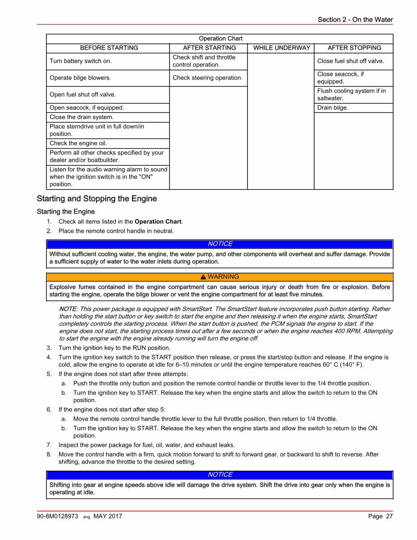
Operation ChartBEFORE STARTING AFTER STARTING WHILE UNDERWAY AFTER STOPPING
Turn battery switch on. Check shift and throttlecontrol operation. Close fuel shut off valve.
Operate bilge blowers. Check steering operation. Close seacock, ifequipped.
Open fuel shut off valve. Flush cooling system if insaltwater.
Open seacock, if equipped. Drain bilge.Close the drain system.Place sterndrive unit in full down/inposition.Check the engine oil.Perform all other checks specified by yourdealer and/or boatbuilder.Listen for the audio warning alarm to soundwhen the ignition switch is in the "ON"position.
Starting and Stopping the EngineStarting the Engine
1. Check all items listed in the Operation Chart.2. Place the remote control handle in neutral.
NOTICEWithout sufficient cooling water, the engine, the water pump, and other components will overheat and suffer damage. Providea sufficient supply of water to the water inlets during operation.
! WARNINGExplosive fumes contained in the engine compartment can cause serious injury or death from fire or explosion. Beforestarting the engine, operate the bilge blower or vent the engine compartment for at least five minutes.
NOTE: This power package is equipped with SmartStart. The SmartStart feature incorporates push button starting. Ratherthan holding the start button or key switch to start the engine and then releasing it when the engine starts, SmartStartcompletely controls the starting process. When the start button is pushed, the PCM signals the engine to start. If theengine does not start, the starting process times out after a few seconds or when the engine reaches 400 RPM. Attemptingto start the engine with the engine already running will turn the engine off.
3. Turn the ignition key to the RUN position.4. Turn the ignition key switch to the START position then release, or press the start/stop button and release. If the engine is
cold, allow the engine to operate at idle for 6–10 minutes or until the engine temperature reaches 60° C (140° F).5. If the engine does not start after three attempts:
a. Push the throttle only button and position the remote control handle or throttle lever to the 1/4 throttle position.b. Turn the ignition key to START. Release the key when the engine starts and allow the switch to return to the ON
position.6. If the engine does not start after step 5:
a. Move the remote control handle throttle lever to the full throttle position, then return to 1/4 throttle.b. Turn the ignition key to START. Release the key when the engine starts and allow the switch to return to the ON
position.7. Inspect the power package for fuel, oil, water, and exhaust leaks.8. Move the control handle with a firm, quick motion forward to shift to forward gear, or backward to shift to reverse. After
shifting, advance the throttle to the desired setting.
NOTICEShifting into gear at engine speeds above idle will damage the drive system. Shift the drive into gear only when the engine isoperating at idle.
Section 2 - On the Water
90-8M0128973 eng MAY 2017 Page 27
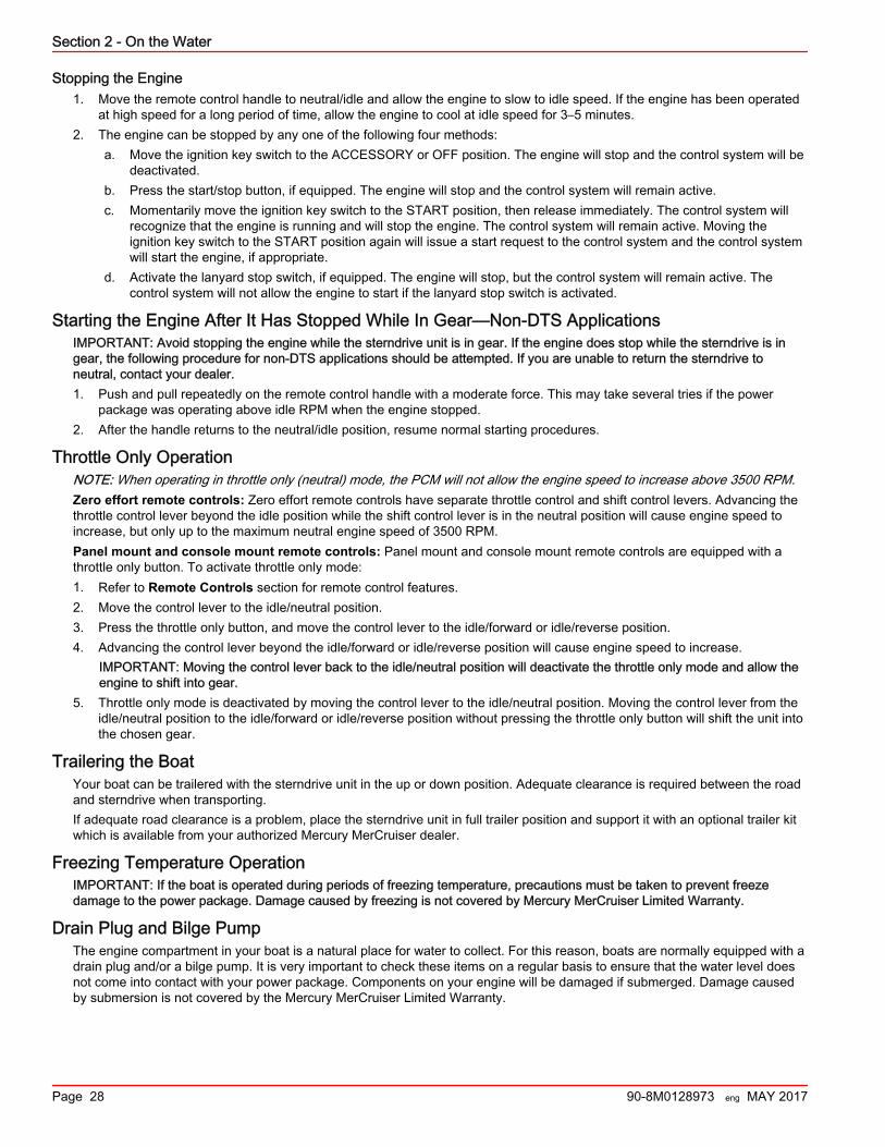
Stopping the Engine1. Move the remote control handle to neutral/idle and allow the engine to slow to idle speed. If the engine has been operated
at high speed for a long period of time, allow the engine to cool at idle speed for 3–5 minutes.2. The engine can be stopped by any one of the following four methods:
a. Move the ignition key switch to the ACCESSORY or OFF position. The engine will stop and the control system will bedeactivated.
b. Press the start/stop button, if equipped. The engine will stop and the control system will remain active.c. Momentarily move the ignition key switch to the START position, then release immediately. The control system will
recognize that the engine is running and will stop the engine. The control system will remain active. Moving theignition key switch to the START position again will issue a start request to the control system and the control systemwill start the engine, if appropriate.
d. Activate the lanyard stop switch, if equipped. The engine will stop, but the control system will remain active. Thecontrol system will not allow the engine to start if the lanyard stop switch is activated.
Starting the Engine After It Has Stopped While In Gear—Non‑DTS ApplicationsIMPORTANT: Avoid stopping the engine while the sterndrive unit is in gear. If the engine does stop while the sterndrive is ingear, the following procedure for non‑DTS applications should be attempted. If you are unable to return the sterndrive toneutral, contact your dealer.1. Push and pull repeatedly on the remote control handle with a moderate force. This may take several tries if the power
package was operating above idle RPM when the engine stopped.2. After the handle returns to the neutral/idle position, resume normal starting procedures.
Throttle Only OperationNOTE: When operating in throttle only (neutral) mode, the PCM will not allow the engine speed to increase above 3500 RPM.Zero effort remote controls: Zero effort remote controls have separate throttle control and shift control levers. Advancing thethrottle control lever beyond the idle position while the shift control lever is in the neutral position will cause engine speed toincrease, but only up to the maximum neutral engine speed of 3500 RPM.Panel mount and console mount remote controls: Panel mount and console mount remote controls are equipped with athrottle only button. To activate throttle only mode:1. Refer to Remote Controls section for remote control features.2. Move the control lever to the idle/neutral position.3. Press the throttle only button, and move the control lever to the idle/forward or idle/reverse position.4. Advancing the control lever beyond the idle/forward or idle/reverse position will cause engine speed to increase.
IMPORTANT: Moving the control lever back to the idle/neutral position will deactivate the throttle only mode and allow theengine to shift into gear.
5. Throttle only mode is deactivated by moving the control lever to the idle/neutral position. Moving the control lever from theidle/neutral position to the idle/forward or idle/reverse position without pressing the throttle only button will shift the unit intothe chosen gear.
Trailering the BoatYour boat can be trailered with the sterndrive unit in the up or down position. Adequate clearance is required between the roadand sterndrive when transporting.If adequate road clearance is a problem, place the sterndrive unit in full trailer position and support it with an optional trailer kitwhich is available from your authorized Mercury MerCruiser dealer.
Freezing Temperature OperationIMPORTANT: If the boat is operated during periods of freezing temperature, precautions must be taken to prevent freezedamage to the power package. Damage caused by freezing is not covered by Mercury MerCruiser Limited Warranty.
Drain Plug and Bilge PumpThe engine compartment in your boat is a natural place for water to collect. For this reason, boats are normally equipped with adrain plug and/or a bilge pump. It is very important to check these items on a regular basis to ensure that the water level doesnot come into contact with your power package. Components on your engine will be damaged if submerged. Damage causedby submersion is not covered by the Mercury MerCruiser Limited Warranty.
Section 2 - On the Water
Page 28 90-8M0128973 eng MAY 2017
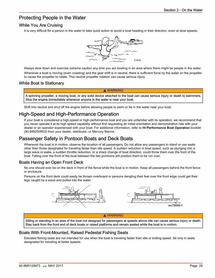
Protecting People in the WaterWhile You Are Cruising
It is very difficult for a person in the water to take quick action to avoid a boat heading in their direction, even at slow speeds.
21604
Always slow down and exercise extreme caution any time you are boating in an area where there might be people in the water.Whenever a boat is moving (even coasting) and the gear shift is in neutral, there is sufficient force by the water on the propellerto cause the propeller to rotate. This neutral propeller rotation can cause serious injury.
While Boat Is Stationary! WARNING
A spinning propeller, a moving boat, or any solid device attached to the boat can cause serious injury or death to swimmers.Stop the engine immediately whenever anyone in the water is near your boat.
Shift into neutral and shut off the engine before allowing people to swim or be in the water near your boat.
High‑Speed and High‑Performance OperationIf your boat is considered a high‑speed or high‑performance boat and you are unfamiliar with its operation, we recommend thatyou never operate it at its high speed capability without first requesting an initial orientation and demonstration ride with yourdealer or an operator experienced with your boat. For additional information, refer to Hi‑Performance Boat Operation booklet(90‑849250R03) from your dealer, distributor, or Mercury Marine.
Passenger Safety in Pontoon Boats and Deck BoatsWhenever the boat is in motion, observe the location of all passengers. Do not allow any passengers to stand or use seatsother than those designated for traveling faster than idle speed. A sudden reduction in boat speed, such as plunging into alarge wave or wake, a sudden throttle reduction, or a sharp change of boat direction, could throw them over the front of theboat. Falling over the front of the boat between the two pontoons will position them to be run over.
Boats Having an Open Front DeckNo one should ever be on the deck in front of the fence while the boat is in motion. Keep all passengers behind the front fenceor enclosure.Persons on the front deck could easily be thrown overboard or persons dangling their feet over the front edge could get theirlegs caught by a wave and pulled into the water.
mc79555-1
! WARNINGSitting or standing in an area of the boat not designed for passengers at speeds above idle can cause serious injury or death.Stay back from the front end of deck boats or raised platforms and remain seated while the boat is in motion.
Boats With Front‑Mounted, Raised Pedestal Fishing SeatsElevated fishing seats are not intended for use when the boat is traveling faster than idle or trolling speed. Sit only in seatsdesignated for traveling at faster speeds.
Section 2 - On the Water
90-8M0128973 eng MAY 2017 Page 29
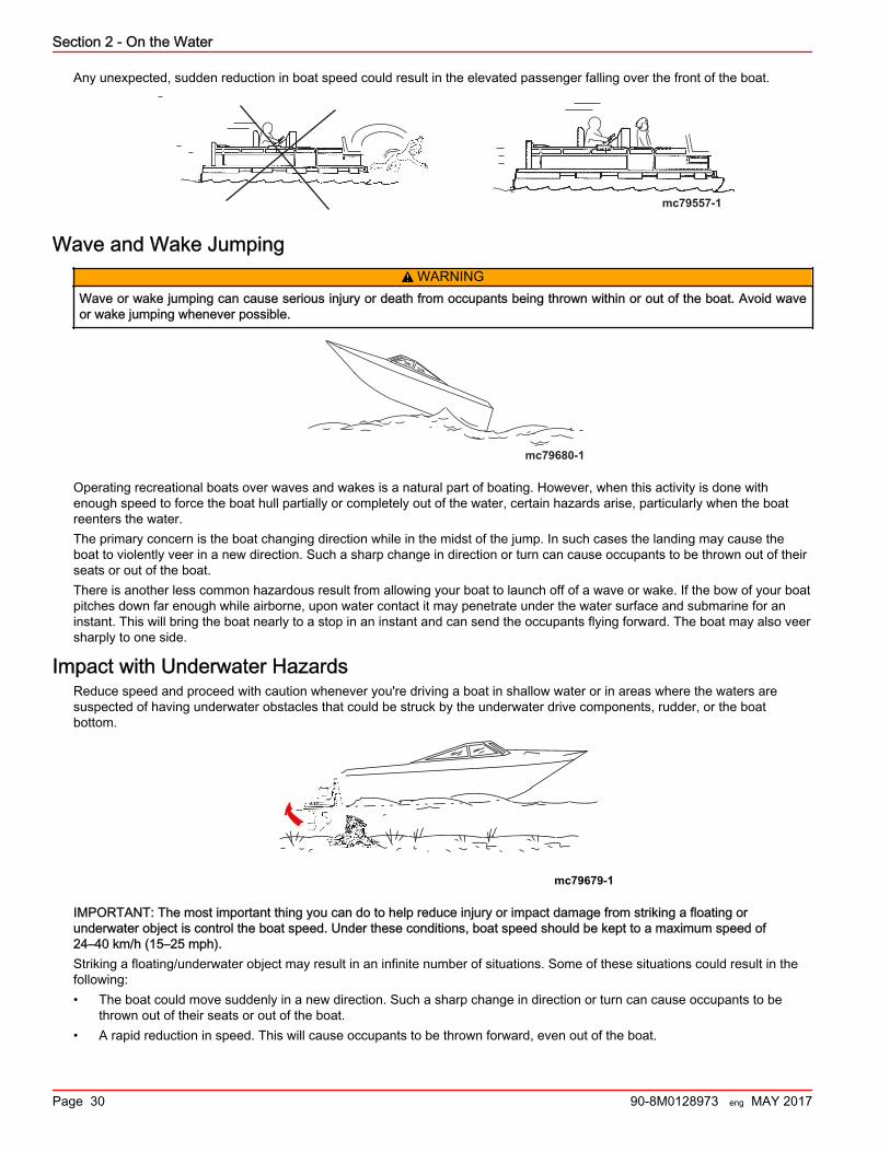
Any unexpected, sudden reduction in boat speed could result in the elevated passenger falling over the front of the boat.
mc79557-1
Wave and Wake Jumping! WARNING
Wave or wake jumping can cause serious injury or death from occupants being thrown within or out of the boat. Avoid waveor wake jumping whenever possible.
mc79680-1
Operating recreational boats over waves and wakes is a natural part of boating. However, when this activity is done withenough speed to force the boat hull partially or completely out of the water, certain hazards arise, particularly when the boatreenters the water.The primary concern is the boat changing direction while in the midst of the jump. In such cases the landing may cause theboat to violently veer in a new direction. Such a sharp change in direction or turn can cause occupants to be thrown out of theirseats or out of the boat.There is another less common hazardous result from allowing your boat to launch off of a wave or wake. If the bow of your boatpitches down far enough while airborne, upon water contact it may penetrate under the water surface and submarine for aninstant. This will bring the boat nearly to a stop in an instant and can send the occupants flying forward. The boat may also veersharply to one side.
Impact with Underwater HazardsReduce speed and proceed with caution whenever you're driving a boat in shallow water or in areas where the waters aresuspected of having underwater obstacles that could be struck by the underwater drive components, rudder, or the boatbottom.
mc79679-1
IMPORTANT: The most important thing you can do to help reduce injury or impact damage from striking a floating orunderwater object is control the boat speed. Under these conditions, boat speed should be kept to a maximum speed of24–40 km/h (15–25 mph).Striking a floating/underwater object may result in an infinite number of situations. Some of these situations could result in thefollowing:• The boat could move suddenly in a new direction. Such a sharp change in direction or turn can cause occupants to be
thrown out of their seats or out of the boat.• A rapid reduction in speed. This will cause occupants to be thrown forward, even out of the boat.
Section 2 - On the Water
Page 30 90-8M0128973 eng MAY 2017
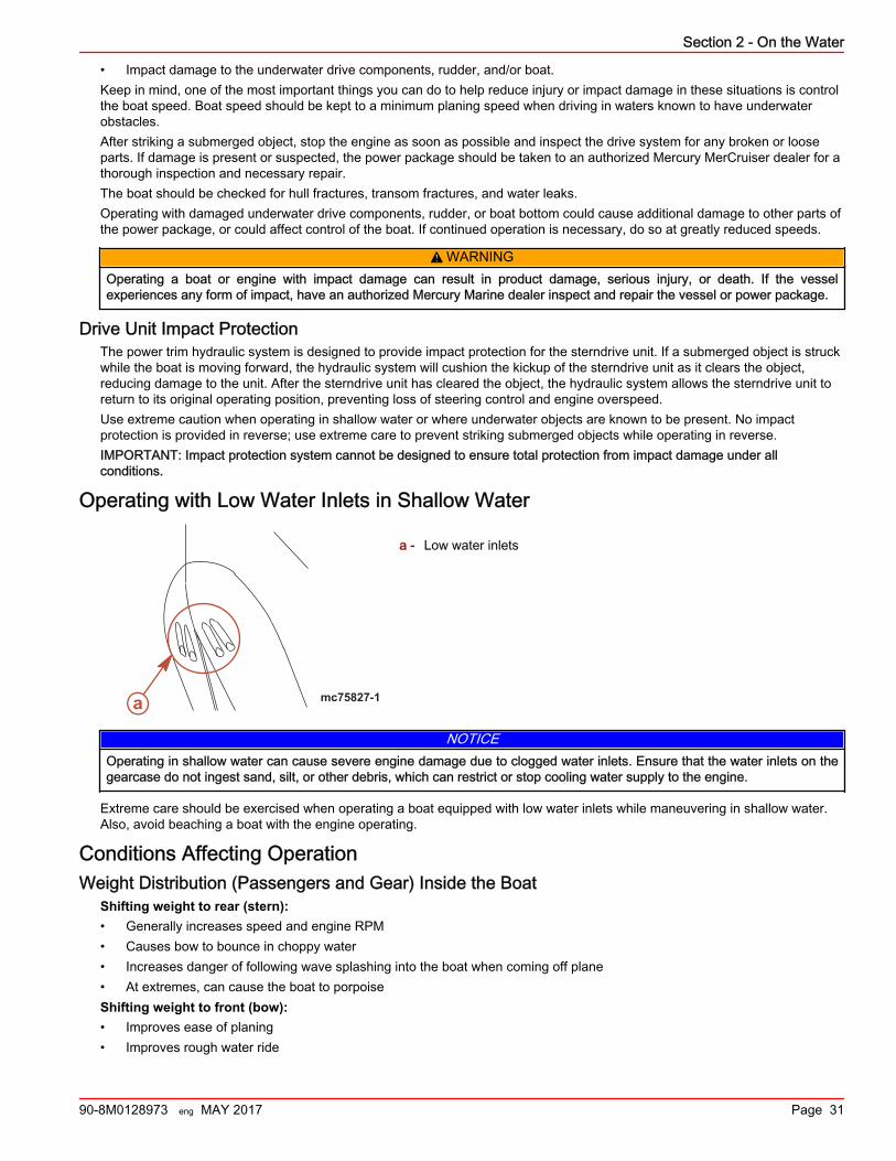
• Impact damage to the underwater drive components, rudder, and/or boat.Keep in mind, one of the most important things you can do to help reduce injury or impact damage in these situations is controlthe boat speed. Boat speed should be kept to a minimum planing speed when driving in waters known to have underwaterobstacles.After striking a submerged object, stop the engine as soon as possible and inspect the drive system for any broken or looseparts. If damage is present or suspected, the power package should be taken to an authorized Mercury MerCruiser dealer for athorough inspection and necessary repair.The boat should be checked for hull fractures, transom fractures, and water leaks.Operating with damaged underwater drive components, rudder, or boat bottom could cause additional damage to other parts ofthe power package, or could affect control of the boat. If continued operation is necessary, do so at greatly reduced speeds.
! WARNINGOperating a boat or engine with impact damage can result in product damage, serious injury, or death. If the vesselexperiences any form of impact, have an authorized Mercury Marine dealer inspect and repair the vessel or power package.
Drive Unit Impact ProtectionThe power trim hydraulic system is designed to provide impact protection for the sterndrive unit. If a submerged object is struckwhile the boat is moving forward, the hydraulic system will cushion the kickup of the sterndrive unit as it clears the object,reducing damage to the unit. After the sterndrive unit has cleared the object, the hydraulic system allows the sterndrive unit toreturn to its original operating position, preventing loss of steering control and engine overspeed.Use extreme caution when operating in shallow water or where underwater objects are known to be present. No impactprotection is provided in reverse; use extreme care to prevent striking submerged objects while operating in reverse.IMPORTANT: Impact protection system cannot be designed to ensure total protection from impact damage under allconditions.
Operating with Low Water Inlets in Shallow Water
a - Low water inlets
NOTICEOperating in shallow water can cause severe engine damage due to clogged water inlets. Ensure that the water inlets on thegearcase do not ingest sand, silt, or other debris, which can restrict or stop cooling water supply to the engine.
Extreme care should be exercised when operating a boat equipped with low water inlets while maneuvering in shallow water.Also, avoid beaching a boat with the engine operating.
Conditions Affecting OperationWeight Distribution (Passengers and Gear) Inside the Boat
Shifting weight to rear (stern):• Generally increases speed and engine RPM• Causes bow to bounce in choppy water• Increases danger of following wave splashing into the boat when coming off plane• At extremes, can cause the boat to porpoiseShifting weight to front (bow):• Improves ease of planing• Improves rough water ride
mc75827-1a
Section 2 - On the Water
90-8M0128973 eng MAY 2017 Page 31
• At extremes, can cause the boat to veer back and forth (bow steer)
The Bottom of the BoatTo maintain maximum speed, the boat bottom should be:• Clean, free of barnacles and marine growth• Free of distortion; nearly flat where it contacts the water• Straight and smooth, fore and aftMarine vegetation may accumulate when the boat is docked. This growth must be removed before operation; it may clog thewater inlets and cause the engine to overheat.
CavitationCavitation occurs when water flow cannot follow the contour of a fast‑moving underwater object, such as a gear housing or apropeller. Cavitation increases propeller speed while reducing boat speed. Cavitation can seriously erode the surface of thegear housing or the propeller. Common causes of cavitation are:• Weeds or other debris snagged on the propeller• Bent propeller blade• Raised burrs or sharp edges on the propeller
VentilationVentilation is caused by surface air or exhaust gases that are introduced around the propeller resulting in propeller speed‑upand a reduction in boat speed. Air bubbles strike the propeller blade and cause erosion of the blade surface. If allowed tocontinue, eventual blade failure (breakage) will occur. Excessive ventilation is usually caused by:• Drive unit trimmed out too far• A missing propeller diffuser ring• A damaged propeller or gear housing, which allows exhaust gases to escape between propeller and gear housing• Drive unit installed too high on transom
Elevation and ClimateElevation and climate changes will affect the performance of your power package. Loss of performance can be caused by:• Higher elevations• Higher temperatures• Low barometric pressures• High humidityFor you to have optimum engine performance under changing weather conditions, it is essential that the engine be propped toallow the engine to operate at or near the top end of the specified maximum RPM range with a normal boat load during yournormal boating weather conditions.In most cases, recommended RPM can be achieved by changing to a lower pitch propeller.
Propeller SelectionGeneral Information
IMPORTANT: The installed propeller must allow the engine to operate at the specified wide‑open throttle (WOT) RPM range.The engine operating range is listed in the specification section of the manual.It is the responsibility of the boat manufacturer or the selling dealer to equip the power package with the correct propeller. Referto Propellers http://www.mercurymarine.com/propellers/prop‑selector.If full throttle operation is below the recommended range, the propeller must be changed to prevent loss of performance andpossible engine damage. Conversely, operating an engine with a propeller that allows the WOT RPM to reach the limiter, maycause a warning horn activation and may record the engine over revolution event in the propulsion control module.After the initial propeller selection, the following common problems may require that the propeller be changed to a lower pitch:• Warmer weather and greater humidity cause an RPM loss• Operating in a higher elevation causes an RPM loss• Operating with increased load (additional passengers, pulling skiers, etc.)For better acceleration, such as is needed for waterskiing, use the next lower pitch propeller. However, do not operate at fullthrottle when using the lower pitch propeller when not pulling skiers.Because of the many variables of boat design, only testing will determine the best propeller for a particular application.Available propellers are listed in the Mercury Precision Parts/Quicksilver Accessories Guide.
Section 2 - On the Water
Page 32 90-8M0128973 eng MAY 2017
Engine RPM LimiterIMPORTANT: This engine is equipped with a RPM limiter. This limit is slightly above the normal operating range of the engineand is designed to help prevent damage from excessive engine RPM. When the engine reaches the RPM limiter, the horn willsound. Once the RPM drops into the recommended operating RPM range, normal engine operation resumes.
Getting Started20‑Hour Break‑In Period
IMPORTANT: The first 20 hours of operation is the engine break‑in period. Correct break‑in is essential to obtain minimum oilconsumption and maximum engine performance. During this break‑in period, the following rules must be observed:• Do not operate below 1500 RPM for extended periods of time for the first 10 hours. Shift into gear as soon as possible after
starting and advance the throttle above 1500 RPM if conditions permit safe operation.• Do not operate at one speed consistently for extended periods.• Do not exceed 3/4 throttle during the first 10 hours. During the next 10 hours, occasional operation at full throttle is
permissible (five minutes at a time maximum).• Avoid full throttle acceleration from idle speed.• Do not operate at full throttle until the engine reaches normal operating temperature.• Frequently check engine oil level. Add oil as needed. It is normal for oil consumption to be high during the break‑in period.
After the Break‑In PeriodTo help extend the life of your Mercury MerCruiser power package, follow these recommendations:• Ensure that the propeller allows the engine to operate at or near the top of the specified wide‑open throttle (WOT) RPM
range. Refer to Specifications and Maintenance.• Operate the engine at 3/4 throttle or lower. Refrain from prolonged operation at WOT RPM.
End of First Season CheckupAt the end of the first season of operation, contact an authorized Mercury MerCruiser dealer to discuss and/or performscheduled maintenance items. If you are in an area where the product is operated continuously, year‑round, you should contactyour dealer at the end of the first 100 hours of operation or once yearly, whichever occurs first.
Section 2 - On the Water
90-8M0128973 eng MAY 2017 Page 33

Section 2 - On the Water
Notes:
Page 34 90-8M0128973 eng MAY 2017
Section 3 - SpecificationsTable of ContentsFuel Requirements............................................................... 36
Fuel Ratings ................................................................. 36Using Reformulated (Oxygenated) Gasoline (USA Only)...................................................................................... 36Gasoline Containing Alcohol ........................................ 36
Bu16 Butanol Fuel Blends ..................................... 36Methanol and Ethanol Fuel Blends ....................... 36
Engine Oil............................................................................. 36Engine Specifications........................................................... 37
4.5L MPI Engine Specifications..................................... 376.2L MPI Engine Specifications..................................... 38
Fluid Specifications............................................................... 38Engine............................................................................38Alpha Sterndrive............................................................ 39Bravo Sterndrives.......................................................... 39Power‑Assisted Steering and Power Trim Fluids.......... 39
Approved Power‑Assisted Steering Fluids ............ 39Approved Power Trim Fluids ................................. 39
3
Section 3 - Specifications
90-8M0128973 eng MAY 2017 Page 35
Fuel RequirementsNOTICE
Running out of fuel can damage catalyst components. Do not allow the fuel tanks to become empty during operation.
IMPORTANT: Use of improper gasoline can damage your engine. Engine damage resulting from the use of impropergasoline is considered misuse of the engine and will not be covered under the limited warranty.
Fuel RatingsMercury MerCruiser engines will operate satisfactorily with any major brand of unleaded gasoline that meets the followingspecifications:USA and Canada ‑ A posted pump octane rating of 87 (R+M)/2, minimum, for all models. Premium gasoline 91 (R+M)/2octane is also acceptable for all models. Do not use leaded gasoline.Outside USA and Canada ‑ A posted pump octane rating of 91 RON, minimum, for all models. Premium gasoline (95 RON) isalso acceptable for all models. Do not use leaded gasoline.
Using Reformulated (Oxygenated) Gasoline (USA Only)Reformulated gasoline is required in certain areas of the USA and is acceptable for use in your Mercury Marine engine. Theonly oxygenate currently in use in the USA is alcohol (ethanol, methanol, or butanol).
Gasoline Containing AlcoholBu16 Butanol Fuel Blends
Fuel blends of up to 16.1% butanol (Bu16) that meet the published Mercury Marine fuel rating requirements are an acceptablesubstitute for unleaded gasoline. Contact your boat manufacturer for specific recommendations on your boat's fuel systemcomponents (fuel tanks, fuel lines, and fittings).
Methanol and Ethanol Fuel BlendsIMPORTANT: The fuel system components on your Mercury Marine engine will withstand up to 10% alcohol (methanol orethanol) content in the gasoline. Your boat's fuel system may not be capable of withstanding the same percentage of alcohol.Contact your boat manufacturer for specific recommendations on your boat's fuel system components (fuel tanks, fuel lines,and fittings).Be aware that gasoline containing methanol or ethanol may cause increased:• Corrosion of metal parts• Deterioration of rubber or plastic parts• Fuel permeation through the rubber fuel lines• Likelihood of phase separation (water and alcohol separating from the gasoline in the fuel tank)
! WARNINGFuel leakage is a fire or explosion hazard, which can cause serious injury or death. Periodically inspect all fuel systemcomponents for leaks, softening, hardening, swelling, or corrosion, particularly after storage. Any sign of leakage ordeterioration requires replacement before further engine operation.
IMPORTANT: If you use gasoline that contains or might contain methanol or ethanol, you must increase the frequency ofinspection for leaks and abnormalities.IMPORTANT: When operating a Mercury Marine engine on gasoline containing methanol or ethanol, do not store the gasolinein the fuel tank for long periods. Cars normally consume these blended fuels before they can absorb enough moisture to causetrouble; boats often sit idle long enough for phase separation to take place. Internal corrosion may occur during storage ifalcohol has washed protective oil films from internal components.
Engine OilFor optimum engine performance and maximum protection, use the following oil:
Application Recommended OilAll MerCruiser engines Mercury/Quicksilver 25W‑40 Synthetic Blend Engine Oil, NMMA FC‑W Catalyst Compatible rated
IMPORTANT: Lubrication requirements for catalyzed engines differ from the requirements for noncatalyzed engines. Somemarine‑grade lubricants contain high levels of phosphorus. Although these high‑phosphorus lubricants may allow acceptableengine performance, exposure over time will damage the catalyst. Catalysts damaged by lubricants containing high levels ofphosphorus may not be covered by the MerCruiser Limited Warranty.
Section 3 - Specifications
Page 36 90-8M0128973 eng MAY 2017
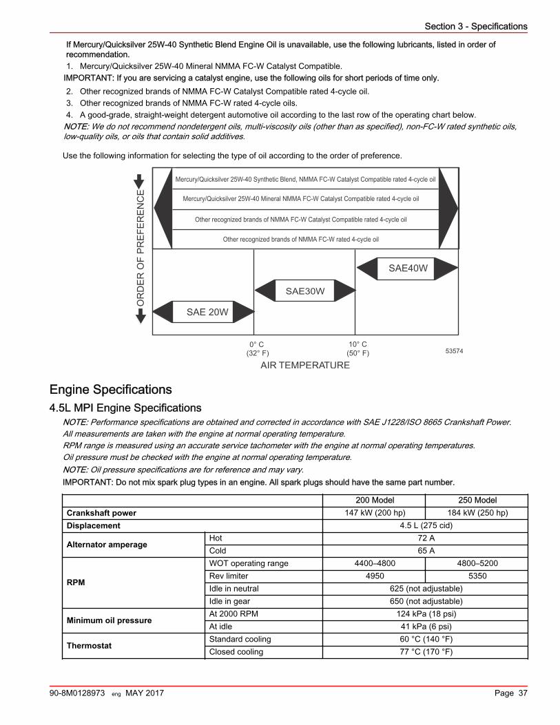
If Mercury/Quicksilver 25W‑40 Synthetic Blend Engine Oil is unavailable, use the following lubricants, listed in order ofrecommendation.1. Mercury/Quicksilver 25W‑40 Mineral NMMA FC‑W Catalyst Compatible.
IMPORTANT: If you are servicing a catalyst engine, use the following oils for short periods of time only.2. Other recognized brands of NMMA FC‑W Catalyst Compatible rated 4‑cycle oil.3. Other recognized brands of NMMA FC‑W rated 4‑cycle oils.4. A good‑grade, straight‑weight detergent automotive oil according to the last row of the operating chart below.
NOTE: We do not recommend nondetergent oils, multi‑viscosity oils (other than as specified), non‑FC‑W rated synthetic oils,low‑quality oils, or oils that contain solid additives.
Use the following information for selecting the type of oil according to the order of preference.
Mercury/Quicksilver 25W-40 Synthetic Blend, NMMA FC-W Catalyst Compatible rated 4-cycle oil
Other recognized brands of NMMA FC-W Catalyst Compatible rated 4-cycle oil
SAE 20W
SAE30W
SAE40W
AIR TEMPERATURE
OR
DE
R O
F P
RE
FER
EN
CE
(32° F) 0° C
(50° F)10° C
Mercury/Quicksilver 25W-40 Mineral NMMA FC-W Catalyst Compatible rated 4-cycle oil
53574
Other recognized brands of NMMA FC-W rated 4-cycle oil
Engine Specifications4.5L MPI Engine Specifications
NOTE: Performance specifications are obtained and corrected in accordance with SAE J1228/ISO 8665 Crankshaft Power.All measurements are taken with the engine at normal operating temperature.RPM range is measured using an accurate service tachometer with the engine at normal operating temperatures.Oil pressure must be checked with the engine at normal operating temperature.NOTE: Oil pressure specifications are for reference and may vary.IMPORTANT: Do not mix spark plug types in an engine. All spark plugs should have the same part number.
200 Model 250 ModelCrankshaft power 147 kW (200 hp) 184 kW (250 hp)Displacement 4.5 L (275 cid)
Alternator amperageHot 72 ACold 65 A
RPM
WOT operating range 4400–4800 4800–5200Rev limiter 4950 5350Idle in neutral 625 (not adjustable)Idle in gear 650 (not adjustable)
Minimum oil pressureAt 2000 RPM 124 kPa (18 psi)At idle 41 kPa (6 psi)
ThermostatStandard cooling 60 °C (140 °F)Closed cooling 77 °C (170 °F)
Section 3 - Specifications
90-8M0128973 eng MAY 2017 Page 37
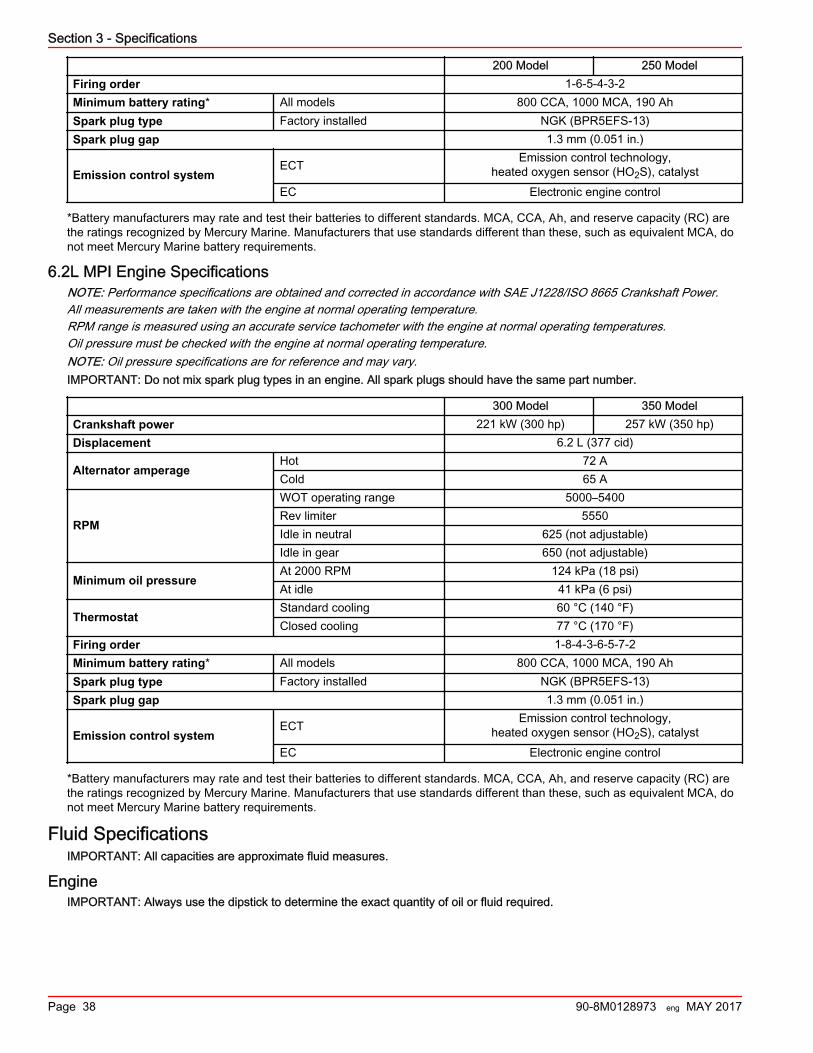
200 Model 250 ModelFiring order 1‑6‑5‑4‑3‑2Minimum battery rating* All models 800 CCA, 1000 MCA, 190 AhSpark plug type Factory installed NGK (BPR5EFS‑13)Spark plug gap 1.3 mm (0.051 in.)
Emission control systemECT Emission control technology,
heated oxygen sensor (HO2S), catalystEC Electronic engine control
*Battery manufacturers may rate and test their batteries to different standards. MCA, CCA, Ah, and reserve capacity (RC) arethe ratings recognized by Mercury Marine. Manufacturers that use standards different than these, such as equivalent MCA, donot meet Mercury Marine battery requirements.
6.2L MPI Engine SpecificationsNOTE: Performance specifications are obtained and corrected in accordance with SAE J1228/ISO 8665 Crankshaft Power.All measurements are taken with the engine at normal operating temperature.RPM range is measured using an accurate service tachometer with the engine at normal operating temperatures.Oil pressure must be checked with the engine at normal operating temperature.NOTE: Oil pressure specifications are for reference and may vary.IMPORTANT: Do not mix spark plug types in an engine. All spark plugs should have the same part number.
300 Model 350 ModelCrankshaft power 221 kW (300 hp) 257 kW (350 hp)Displacement 6.2 L (377 cid)
Alternator amperageHot 72 ACold 65 A
RPM
WOT operating range 5000–5400Rev limiter 5550Idle in neutral 625 (not adjustable)Idle in gear 650 (not adjustable)
Minimum oil pressureAt 2000 RPM 124 kPa (18 psi)At idle 41 kPa (6 psi)
ThermostatStandard cooling 60 °C (140 °F)Closed cooling 77 °C (170 °F)
Firing order 1‑8‑4‑3‑6‑5‑7‑2Minimum battery rating* All models 800 CCA, 1000 MCA, 190 AhSpark plug type Factory installed NGK (BPR5EFS‑13)Spark plug gap 1.3 mm (0.051 in.)
Emission control systemECT Emission control technology,
heated oxygen sensor (HO2S), catalystEC Electronic engine control
*Battery manufacturers may rate and test their batteries to different standards. MCA, CCA, Ah, and reserve capacity (RC) arethe ratings recognized by Mercury Marine. Manufacturers that use standards different than these, such as equivalent MCA, donot meet Mercury Marine battery requirements.
Fluid SpecificationsIMPORTANT: All capacities are approximate fluid measures.
EngineIMPORTANT: Always use the dipstick to determine the exact quantity of oil or fluid required.
Section 3 - Specifications
Page 38 90-8M0128973 eng MAY 2017
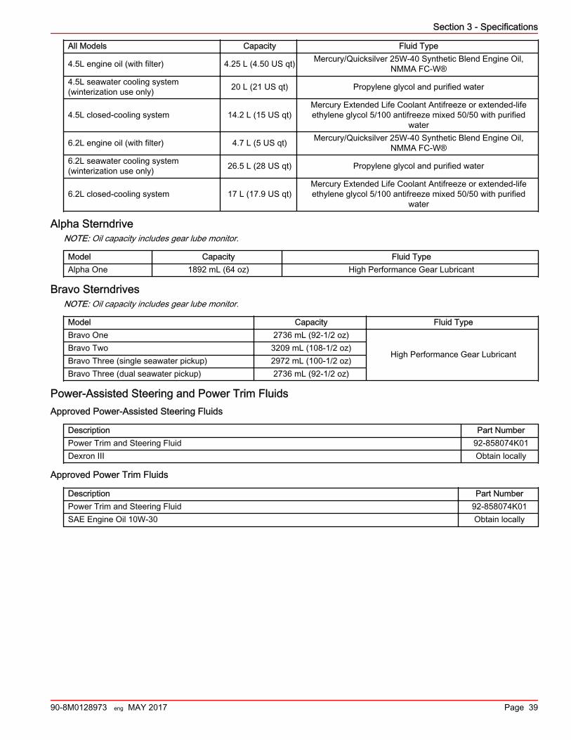
All Models Capacity Fluid Type
4.5L engine oil (with filter) 4.25 L (4.50 US qt) Mercury/Quicksilver 25W‑40 Synthetic Blend Engine Oil,NMMA FC‑W®
4.5L seawater cooling system(winterization use only) 20 L (21 US qt) Propylene glycol and purified water
4.5L closed‑cooling system 14.2 L (15 US qt)Mercury Extended Life Coolant Antifreeze or extended‑lifeethylene glycol 5/100 antifreeze mixed 50/50 with purified
water
6.2L engine oil (with filter) 4.7 L (5 US qt) Mercury/Quicksilver 25W‑40 Synthetic Blend Engine Oil,NMMA FC‑W®
6.2L seawater cooling system(winterization use only) 26.5 L (28 US qt) Propylene glycol and purified water
6.2L closed‑cooling system 17 L (17.9 US qt)Mercury Extended Life Coolant Antifreeze or extended‑lifeethylene glycol 5/100 antifreeze mixed 50/50 with purified
water
Alpha SterndriveNOTE: Oil capacity includes gear lube monitor.
Model Capacity Fluid TypeAlpha One 1892 mL (64 oz) High Performance Gear Lubricant
Bravo SterndrivesNOTE: Oil capacity includes gear lube monitor.
Model Capacity Fluid TypeBravo One 2736 mL (92‑1/2 oz)
High Performance Gear LubricantBravo Two 3209 mL (108‑1/2 oz)Bravo Three (single seawater pickup) 2972 mL (100‑1/2 oz)Bravo Three (dual seawater pickup) 2736 mL (92‑1/2 oz)
Power‑Assisted Steering and Power Trim FluidsApproved Power-Assisted Steering Fluids
Description Part NumberPower Trim and Steering Fluid 92‑858074K01Dexron III Obtain locally
Approved Power Trim Fluids
Description Part NumberPower Trim and Steering Fluid 92‑858074K01SAE Engine Oil 10W‑30 Obtain locally
Section 3 - Specifications
90-8M0128973 eng MAY 2017 Page 39

Section 3 - Specifications
Notes:
Page 40 90-8M0128973 eng MAY 2017
Section 4 - MaintenanceTable of ContentsService Decals...................................................................... 42
Closed Cooling Service Decals ‑ Alpha and Bravo Drive...................................................................................... 42Bravo Standard Cooling Service Decal ........................ 42Alpha Standard Cooling Service Decal ........................ 43
Additional Operation Instructions for Joystick PilotingSterndrive (JPS)................................................................... 43Owner/Operator Responsibilities.......................................... 43Dealer Responsibilities......................................................... 43Maintenance......................................................................... 43Do‑It‑Yourself Maintenance Suggestions............................. 44Inspection............................................................................. 44MerCruiser Gas Sterndrive Inspection and MaintenanceSchedule............................................................................... 44
Daily Checks ................................................................. 44After Each Use ............................................................. 45Weekly Checks ............................................................. 45Every Two Months or 50 Hours .................................... 45Annually or 100 Hours .................................................. 45Three Years or 300 Hours ............................................ 45Five Years or 500 Hours ............................................... 46
Engine Oil............................................................................. 46Checking........................................................................ 46
Oil Level—Overfilled .............................................. 46Filling............................................................................. 46Changing Oil and Filter.................................................. 47Engine Oil Drain Pump.................................................. 47Changing Filter.............................................................. 48
Power Steering Fluid............................................................ 48Checking ....................................................................... 48Filling ............................................................................ 49Changing ...................................................................... 49
Engine Coolant ‑ Closed‑Cooling......................................... 49Checking........................................................................ 49Filling............................................................................. 50Changing ...................................................................... 50
Alpha Sterndrive Gear Lube................................................. 51Checking ....................................................................... 51Filling ............................................................................ 51Changing ...................................................................... 51
Bravo Sterndrive Gear Lube................................................. 52Checking........................................................................ 52Filling............................................................................. 53Changing....................................................................... 53
Power Trim Fluid.................................................................. 55Checking ....................................................................... 55Filling ............................................................................ 55Changing ...................................................................... 55
Battery.................................................................................. 55Auxiliary Batteries.......................................................... 55Multiple EFI Engine Battery Precautions....................... 56
Flame Arrestor...................................................................... 56Changing the Positive Crankcase Ventilation (PCV) Valve.............................................................................................. 58
Fuel System Maintenance.................................................... 59Fuel System................................................................... 59Fuel Line Inspection.......................................................59Water‑Separating Fuel Filter..........................................59
Filter Housing Removal ......................................... 59Draining the Filter Housing .................................... 60Fuel Filter Inspection ............................................. 60Filter Housing Installation ...................................... 60
Lubrication............................................................................ 61Steering System............................................................ 61Remote Control Cable Lubrication.................................62Driveshaft U‑joint Splines and O‑Rings (Sterndrive UnitRemoved)...................................................................... 63Engine Coupler.............................................................. 63Engine Coupler.............................................................. 63Driveshaft Extension Models......................................... 64
Propellers............................................................................. 64Propeller Repair............................................................. 64Alpha or Bravo One Propeller Removal.........................65Alpha or Bravo One Propeller Installation......................65Bravo Two Propeller Removal....................................... 66Bravo Two Propeller Installation.................................... 66Bravo Three Propeller Removal.................................... 67Bravo Three Propeller Installation................................. 68
Serpentine Drive Belt............................................................ 69Serpentine Drive Belt Routing....................................... 69Serpentine Belt Failure Identification............................. 70Checking........................................................................ 71Replacing....................................................................... 72
Corrosion Protection............................................................. 72Corrosion Information.................................................... 72Maintaining Ground Circuit Continuity........................... 72Sterndrive Corrosion Protection Components............... 73MerCathode System Battery Requirements.................. 75MerCathode Control Module..........................................76MerCathode Theory of Operation.................................. 76Do Not Use Caustic Cleaning Chemicals...................... 77Power Package Exterior Surfaces................................. 77Boat Bottom Care.......................................................... 77Painting Your Power Package....................................... 77Sterndrive Surface Care................................................ 78
Important Information About Flushing Procedures............... 79Flushing Attachments ................................................... 79
Flushing the Power Package (Alpha Models)....................... 79Alpha Models with Standard Cooling............................. 79
Sterndrive Water Pickups ...................................... 79Alpha Models with Closed Cooling................................ 80
Sterndrive Water Pickups ...................................... 81Flushing the Power Package—Bravo Models...................... 82
Flushing Attachments ............................................ 82Sterndrive Water Pickups ...................................... 83Alternative Water Pickups ..................................... 84
SeaCore Power Package Flushing Procedure.............. 85Models Using the Sterndrive Water Pickup ........... 85
4
Section 4 - Maintenance
90-8M0128973 eng MAY 2017 Page 41
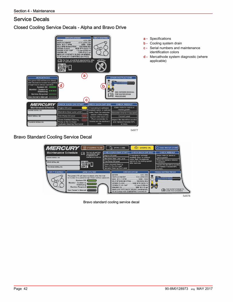
Service DecalsClosed Cooling Service Decals ‑ Alpha and Bravo Drive
a - Specificationsb - Cooling system drainc - Serial numbers and maintenance
identification colorsd - Mercathode system diagnostic (where
applicable)
Bravo Standard Cooling Service Decal
54978
Bravo standard cooling service decal
a
b
c
d
54977
Section 4 - Maintenance
Page 42 90-8M0128973 eng MAY 2017
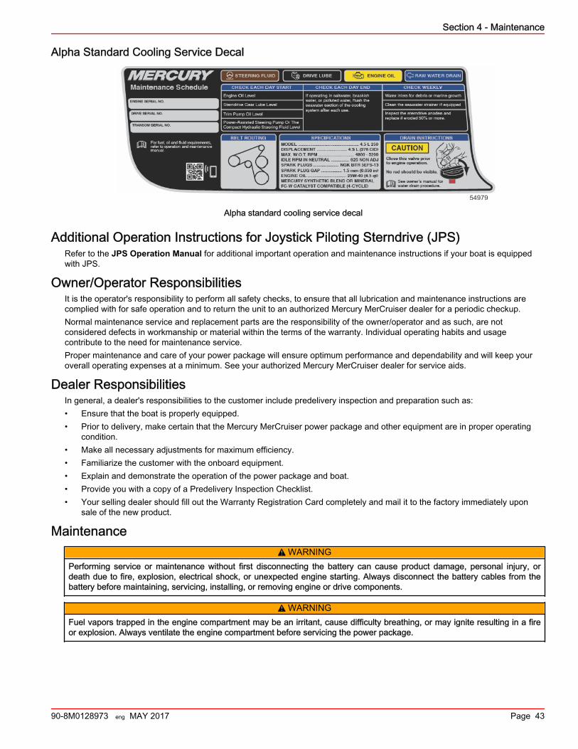
Alpha Standard Cooling Service Decal
54979
Alpha standard cooling service decal
Additional Operation Instructions for Joystick Piloting Sterndrive (JPS)Refer to the JPS Operation Manual for additional important operation and maintenance instructions if your boat is equippedwith JPS.
Owner/Operator ResponsibilitiesIt is the operator's responsibility to perform all safety checks, to ensure that all lubrication and maintenance instructions arecomplied with for safe operation and to return the unit to an authorized Mercury MerCruiser dealer for a periodic checkup.Normal maintenance service and replacement parts are the responsibility of the owner/operator and as such, are notconsidered defects in workmanship or material within the terms of the warranty. Individual operating habits and usagecontribute to the need for maintenance service.Proper maintenance and care of your power package will ensure optimum performance and dependability and will keep youroverall operating expenses at a minimum. See your authorized Mercury MerCruiser dealer for service aids.
Dealer ResponsibilitiesIn general, a dealer's responsibilities to the customer include predelivery inspection and preparation such as:• Ensure that the boat is properly equipped.• Prior to delivery, make certain that the Mercury MerCruiser power package and other equipment are in proper operating
condition.• Make all necessary adjustments for maximum efficiency.• Familiarize the customer with the onboard equipment.• Explain and demonstrate the operation of the power package and boat.• Provide you with a copy of a Predelivery Inspection Checklist.• Your selling dealer should fill out the Warranty Registration Card completely and mail it to the factory immediately upon
sale of the new product.
Maintenance! WARNING
Performing service or maintenance without first disconnecting the battery can cause product damage, personal injury, ordeath due to fire, explosion, electrical shock, or unexpected engine starting. Always disconnect the battery cables from thebattery before maintaining, servicing, installing, or removing engine or drive components.
! WARNINGFuel vapors trapped in the engine compartment may be an irritant, cause difficulty breathing, or may ignite resulting in a fireor explosion. Always ventilate the engine compartment before servicing the power package.
Section 4 - Maintenance
90-8M0128973 eng MAY 2017 Page 43
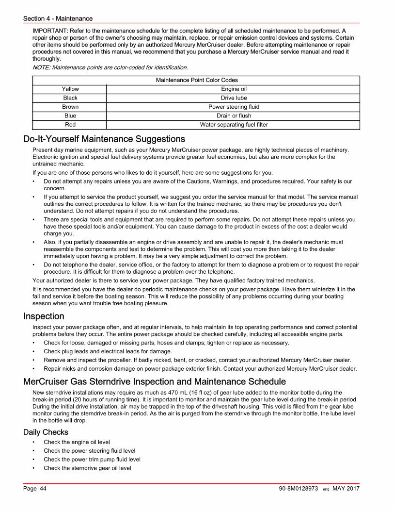
IMPORTANT: Refer to the maintenance schedule for the complete listing of all scheduled maintenance to be performed. Arepair shop or person of the owner's choosing may maintain, replace, or repair emission control devices and systems. Certainother items should be performed only by an authorized Mercury MerCruiser dealer. Before attempting maintenance or repairprocedures not covered in this manual, we recommend that you purchase a Mercury MerCruiser service manual and read itthoroughly.NOTE: Maintenance points are color‑coded for identification.
Maintenance Point Color CodesYellow Engine oilBlack Drive lubeBrown Power steering fluidBlue Drain or flushRed Water separating fuel filter
Do‑It‑Yourself Maintenance SuggestionsPresent day marine equipment, such as your Mercury MerCruiser power package, are highly technical pieces of machinery.Electronic ignition and special fuel delivery systems provide greater fuel economies, but also are more complex for theuntrained mechanic.If you are one of those persons who likes to do it yourself, here are some suggestions for you.• Do not attempt any repairs unless you are aware of the Cautions, Warnings, and procedures required. Your safety is our
concern.• If you attempt to service the product yourself, we suggest you order the service manual for that model. The service manual
outlines the correct procedures to follow. It is written for the trained mechanic, so there may be procedures you don'tunderstand. Do not attempt repairs if you do not understand the procedures.
• There are special tools and equipment that are required to perform some repairs. Do not attempt these repairs unless youhave these special tools and/or equipment. You can cause damage to the product in excess of the cost a dealer wouldcharge you.
• Also, if you partially disassemble an engine or drive assembly and are unable to repair it, the dealer's mechanic mustreassemble the components and test to determine the problem. This will cost you more than taking it to the dealerimmediately upon having a problem. It may be a very simple adjustment to correct the problem.
• Do not telephone the dealer, service office, or the factory to attempt for them to diagnose a problem or to request the repairprocedure. It is difficult for them to diagnose a problem over the telephone.
Your authorized dealer is there to service your power package. They have qualified factory trained mechanics.It is recommended you have the dealer do periodic maintenance checks on your power package. Have them winterize it in thefall and service it before the boating season. This will reduce the possibility of any problems occurring during your boatingseason when you want trouble free boating pleasure.
InspectionInspect your power package often, and at regular intervals, to help maintain its top operating performance and correct potentialproblems before they occur. The entire power package should be checked carefully, including all accessible engine parts.• Check for loose, damaged or missing parts, hoses and clamps; tighten or replace as necessary.• Check plug leads and electrical leads for damage.• Remove and inspect the propeller. If badly nicked, bent, or cracked, contact your authorized Mercury MerCruiser dealer.• Repair nicks and corrosion damage on power package exterior finish. Contact your authorized Mercury MerCruiser dealer.
MerCruiser Gas Sterndrive Inspection and Maintenance ScheduleNew sterndrive installations may require as much as 470 mL (16 fl oz) of gear lube added to the monitor bottle during thebreak‑in period (20 hours of running time). It is important to monitor and maintain the gear lube level during the break‑in period.During the initial drive installation, air may be trapped in the top of the driveshaft housing. This void is filled from the gear lubemonitor during the sterndrive break‑in period. As the air is purged from the sterndrive through the monitor bottle, the lube levelin the bottle will drop.
Daily Checks• Check the engine oil level• Check the power steering fluid level• Check the power trim pump fluid level• Check the sterndrive gear oil level
Section 4 - Maintenance
Page 44 90-8M0128973 eng MAY 2017
• Check the lanyard stop switch
After Each Use• Flush the engine with fresh water, brackish or saltwater use only
Weekly Checks• Check the seawater inlets for marine growth• Clean the seawater strainer, if equipped• Check the coolant level, if equipped• Inspect the anodes• Verify the operation of the MerCathode module, if equipped
Every Two Months or 50 Hours• Lubricate the engine coupler 1.
Annually or 100 Hours• Lubricate the engine coupler 1.
• Lubricate the propeller shaft splines• Clean the gauges and check wire connection—dealer item• Check the torque of the propeller nut• Check the battery condition and connections—dealer item• Touch up any paint nicks and spray the power package with Corrosion Guard• Change the engine oil and filter• Change the sterndrive gear oil• Check the closed cooling fluid level and concentration for freeze protection, if equipped• Replace the water‑separating fuel filter• Clean the crankcase vent—8.2L only• Clean the IAC muffler—8.2L only• Clean the flame arrestor—8.2L only• Inspect the condition of the accessory drive belt—dealer item• Tighten the connection of the gimbal ring to the steering shaft—dealer item• Check the steering system for loose components—dealer item• Check the remote control system for loose components—dealer item• Check the MerCathode module operation for proper protection and check the continuity circuit—dealer item• Replace the PCV valve• Jackshaft models—check U‑joints and tailstock bearings—dealer item• Spray the power package with Corrosion Guard• Inspect anodes, if equipped
Three Years or 300 Hours• Inspect the spark plugs and spark plug wires 2.
• Clean the flame arrestor and crankcase vent hoses• Check the engine mount fasteners for tightness and tighten to the specified torque—dealer item• Check the electrical system for loose, damaged, or corroded fasteners—dealer item• Check the exhaust and cooling system hose clamps for tightness. Inspect for damage or leaks—dealer item.• Inspect and clean seawater side of closed cooling system, if equipped—dealer item• Clean, inspect, and test the closed cooling pressure cap, if equipped—dealer item• Inspect seawater pump. Replace worn components—dealer item.• Inspect the exhaust system. If the power package is equipped with water shutters, verify they are not missing or damaged
—dealer item.• Check the engine alignment—dealer item
1. Power packages that are used extensively at idle or trolling speeds must have the coupler lubricated every 50 hours.2. Inspect the condition of the spark plugs and spark plug wires. Replace as necessary. If the condition of these components is satisfactory, repeat the inspection every 100 hours or once a year,
whichever occurs first.
Section 4 - Maintenance
90-8M0128973 eng MAY 2017 Page 45
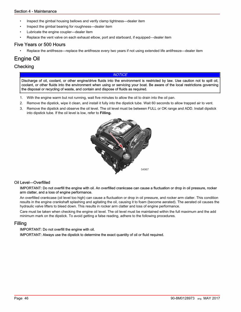
• Inspect the gimbal housing bellows and verify clamp tightness—dealer item• Inspect the gimbal bearing for roughness—dealer item• Lubricate the engine coupler—dealer item• Replace the vent valve on each exhaust elbow, port and starboard, if equipped—dealer item
Five Years or 500 Hours• Replace the antifreeze—replace the antifreeze every two years if not using extended life antifreeze—dealer item
Engine OilChecking
NOTICEDischarge of oil, coolant, or other engine/drive fluids into the environment is restricted by law. Use caution not to spill oil,coolant, or other fluids into the environment when using or servicing your boat. Be aware of the local restrictions governingthe disposal or recycling of waste, and contain and dispose of fluids as required.
1. With the engine warm but not running, wait five minutes to allow the oil to drain into the oil pan.2. Remove the dipstick, wipe it clean, and install it fully into the dipstick tube. Wait 60 seconds to allow trapped air to vent.3. Remove the dipstick and observe the oil level. The oil level must be between FULL or OK range and ADD. Install dipstick
into dipstick tube. If the oil level is low, refer to Filling.
54967
Oil Level—OverfilledIMPORTANT: Do not overfill the engine with oil. An overfilled crankcase can cause a fluctuation or drop in oil pressure, rockerarm clatter, and a loss of engine performance.An overfilled crankcase (oil level too high) can cause a fluctuation or drop in oil pressure, and rocker arm clatter. This conditionresults in the engine crankshaft splashing and agitating the oil, causing it to foam (become aerated). The aerated oil causes thehydraulic valve lifters to bleed down. This results in rocker arm clatter and loss of engine performance.Care must be taken when checking the engine oil level. The oil level must be maintained within the full maximum and the addminimum mark on the dipstick. To avoid getting a false reading, adhere to the following procedures.
FillingIMPORTANT: Do not overfill the engine with oil.IMPORTANT: Always use the dipstick to determine the exact quantity of oil or fluid required.
Section 4 - Maintenance
Page 46 90-8M0128973 eng MAY 2017
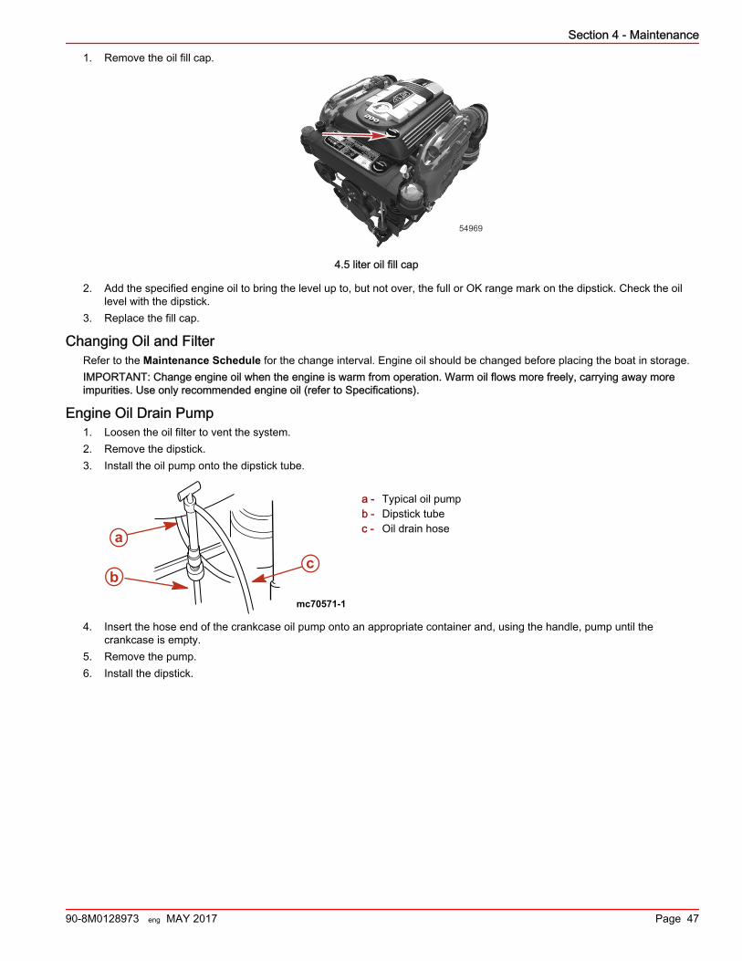
1. Remove the oil fill cap.
54969
4.5 liter oil fill cap
2. Add the specified engine oil to bring the level up to, but not over, the full or OK range mark on the dipstick. Check the oillevel with the dipstick.
3. Replace the fill cap.
Changing Oil and FilterRefer to the Maintenance Schedule for the change interval. Engine oil should be changed before placing the boat in storage.IMPORTANT: Change engine oil when the engine is warm from operation. Warm oil flows more freely, carrying away moreimpurities. Use only recommended engine oil (refer to Specifications).
Engine Oil Drain Pump1. Loosen the oil filter to vent the system.2. Remove the dipstick.3. Install the oil pump onto the dipstick tube.
a - Typical oil pumpb - Dipstick tubec - Oil drain hose
4. Insert the hose end of the crankcase oil pump onto an appropriate container and, using the handle, pump until thecrankcase is empty.
5. Remove the pump.6. Install the dipstick.
mc70571-1
a
cb
Section 4 - Maintenance
90-8M0128973 eng MAY 2017 Page 47
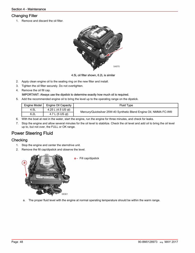
Changing Filter1. Remove and discard the oil filter.
54970
4.5L oil filter shown, 6.2L is similar
2. Apply clean engine oil to the sealing ring on the new filter and install.3. Tighten the oil filter securely. Do not overtighten.4. Remove the oil fill cap.
IMPORTANT: Always use the dipstick to determine exactly how much oil is required.5. Add the recommended engine oil to bring the level up to the operating range on the dipstick.
Engine Model Engine Oil Capacity Fluid Type4.5L 4.25 L (4.5 US qt)
Mercury/Quicksilver 25W‑40 Synthetic Blend Engine Oil, NMMA FC‑W®6.2L 4.7 L (5 US qt)
6. With the boat at rest in the water, start the engine, run the engine for three minutes, and check for leaks.7. Stop the engine and allow several minutes for the oil level to stabilize. Check the oil level and add oil to bring the oil level
up to, but not over, the FULL or OK range.
Power Steering FluidChecking
1. Stop the engine and center the sterndrive unit.2. Remove the fill cap/dipstick and observe the level.
a - Fill cap/dipstick
a. The proper fluid level with the engine at normal operating temperature should be within the warm range.
a
58361
Section 4 - Maintenance
Page 48 90-8M0128973 eng MAY 2017
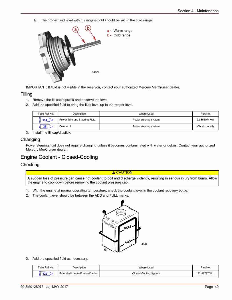
b. The proper fluid level with the engine cold should be within the cold range.
a - Warm rangeb - Cold range
IMPORTANT: If fluid is not visible in the reservoir, contact your authorized Mercury MerCruiser dealer.
Filling1. Remove the fill cap/dipstick and observe the level.2. Add the specified fluid to bring the fluid level up to the proper level.
Tube Ref No. Description Where Used Part No.
114 Power Trim and Steering Fluid Power steering system 92-858074K01
28 Dexron III Power steering system Obtain Locally
3. Install the fill cap/dipstick.
ChangingPower steering fluid does not require changing unless it becomes contaminated with water or debris. Contact your authorizedMercury MerCruiser dealer.
Engine Coolant ‑ Closed‑CoolingChecking
! CAUTIONA sudden loss of pressure can cause hot coolant to boil and discharge violently, resulting in serious injury from burns. Allowthe engine to cool down before removing the coolant pressure cap.
1. With the engine at normal operating temperature, check the coolant level in the coolant recovery bottle.2. The coolant level should be between the ADD and FULL marks.
6102
3. Add the specified fluid as necessary.
Tube Ref No. Description Where Used Part No.
122 Extended Life Antifreeze/Coolant Closed-Cooling System 92-877770K1
54972
a b
Section 4 - Maintenance
90-8M0128973 eng MAY 2017 Page 49
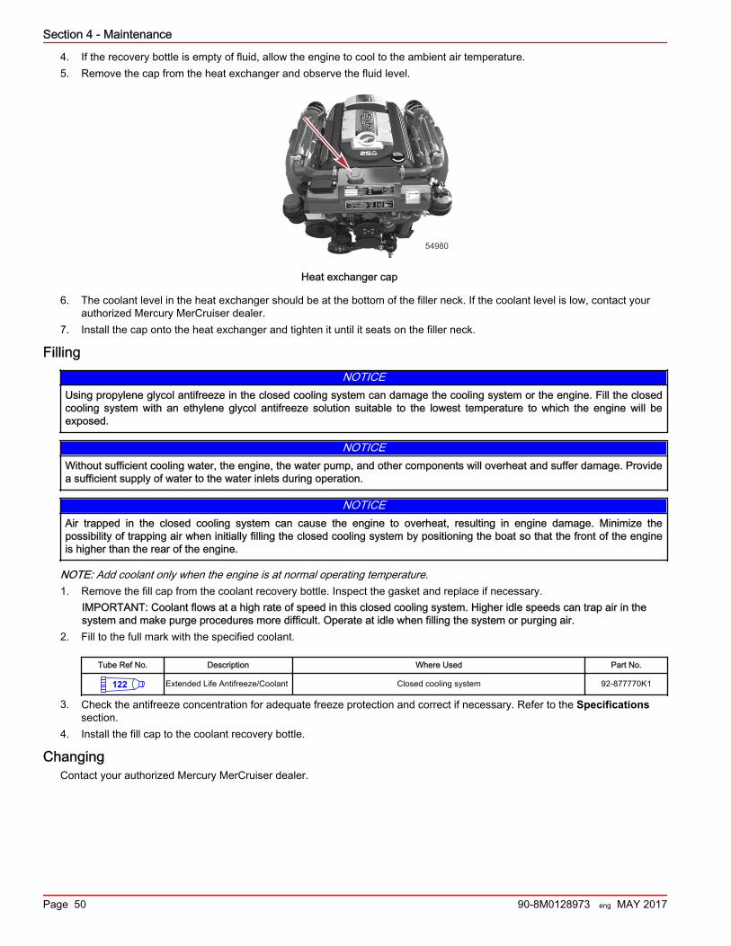
4. If the recovery bottle is empty of fluid, allow the engine to cool to the ambient air temperature.5. Remove the cap from the heat exchanger and observe the fluid level.
54980
Heat exchanger cap
6. The coolant level in the heat exchanger should be at the bottom of the filler neck. If the coolant level is low, contact yourauthorized Mercury MerCruiser dealer.
7. Install the cap onto the heat exchanger and tighten it until it seats on the filler neck.
FillingNOTICE
Using propylene glycol antifreeze in the closed cooling system can damage the cooling system or the engine. Fill the closedcooling system with an ethylene glycol antifreeze solution suitable to the lowest temperature to which the engine will beexposed.
NOTICEWithout sufficient cooling water, the engine, the water pump, and other components will overheat and suffer damage. Providea sufficient supply of water to the water inlets during operation.
NOTICEAir trapped in the closed cooling system can cause the engine to overheat, resulting in engine damage. Minimize thepossibility of trapping air when initially filling the closed cooling system by positioning the boat so that the front of the engineis higher than the rear of the engine.
NOTE: Add coolant only when the engine is at normal operating temperature.1. Remove the fill cap from the coolant recovery bottle. Inspect the gasket and replace if necessary.
IMPORTANT: Coolant flows at a high rate of speed in this closed cooling system. Higher idle speeds can trap air in thesystem and make purge procedures more difficult. Operate at idle when filling the system or purging air.
2. Fill to the full mark with the specified coolant.
Tube Ref No. Description Where Used Part No.
122 Extended Life Antifreeze/Coolant Closed cooling system 92-877770K1
3. Check the antifreeze concentration for adequate freeze protection and correct if necessary. Refer to the Specificationssection.
4. Install the fill cap to the coolant recovery bottle.
ChangingContact your authorized Mercury MerCruiser dealer.
Section 4 - Maintenance
Page 50 90-8M0128973 eng MAY 2017
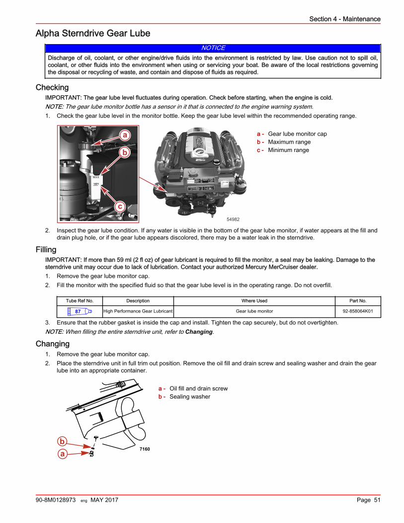
Alpha Sterndrive Gear LubeNOTICE
Discharge of oil, coolant, or other engine/drive fluids into the environment is restricted by law. Use caution not to spill oil,coolant, or other fluids into the environment when using or servicing your boat. Be aware of the local restrictions governingthe disposal or recycling of waste, and contain and dispose of fluids as required.
CheckingIMPORTANT: The gear lube level fluctuates during operation. Check before starting, when the engine is cold.NOTE: The gear lube monitor bottle has a sensor in it that is connected to the engine warning system.1. Check the gear lube level in the monitor bottle. Keep the gear lube level within the recommended operating range.
a - Gear lube monitor capb - Maximum rangec - Minimum range
2. Inspect the gear lube condition. If any water is visible in the bottom of the gear lube monitor, if water appears at the fill anddrain plug hole, or if the gear lube appears discolored, there may be a water leak in the sterndrive.
FillingIMPORTANT: If more than 59 ml (2 fl oz) of gear lubricant is required to fill the monitor, a seal may be leaking. Damage to thesterndrive unit may occur due to lack of lubrication. Contact your authorized Mercury MerCruiser dealer.1. Remove the gear lube monitor cap.2. Fill the monitor with the specified fluid so that the gear lube level is in the operating range. Do not overfill.
Tube Ref No. Description Where Used Part No.
87 High Performance Gear Lubricant Gear lube monitor 92-858064K01
3. Ensure that the rubber gasket is inside the cap and install. Tighten the cap securely, but do not overtighten.NOTE: When filling the entire sterndrive unit, refer to Changing.
Changing1. Remove the gear lube monitor cap.2. Place the sterndrive unit in full trim out position. Remove the oil fill and drain screw and sealing washer and drain the gear
lube into an appropriate container.
a - Oil fill and drain screwb - Sealing washer
MAX
MIN
b
c
a
54982
ab
7160
Section 4 - Maintenance
90-8M0128973 eng MAY 2017 Page 51
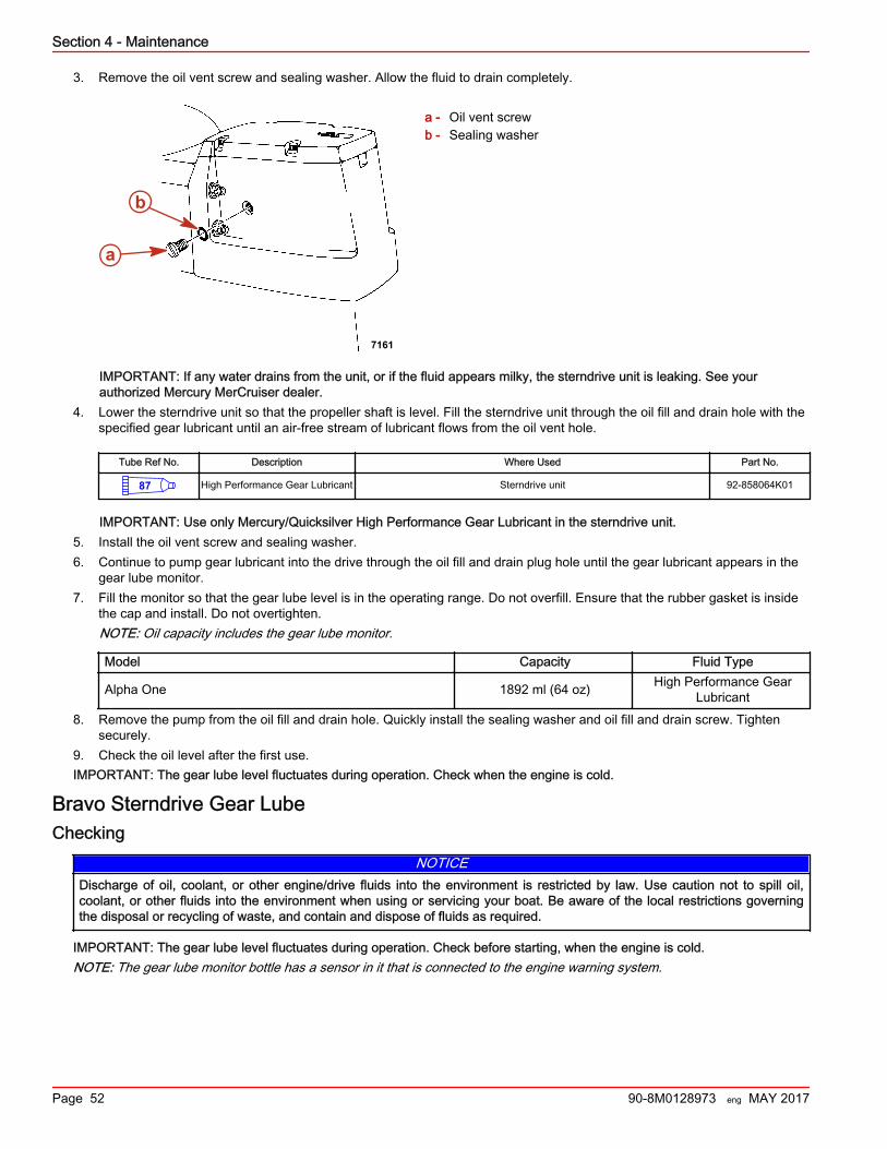
3. Remove the oil vent screw and sealing washer. Allow the fluid to drain completely.
a - Oil vent screwb - Sealing washer
IMPORTANT: If any water drains from the unit, or if the fluid appears milky, the sterndrive unit is leaking. See yourauthorized Mercury MerCruiser dealer.
4. Lower the sterndrive unit so that the propeller shaft is level. Fill the sterndrive unit through the oil fill and drain hole with thespecified gear lubricant until an air‑free stream of lubricant flows from the oil vent hole.
Tube Ref No. Description Where Used Part No.
87 High Performance Gear Lubricant Sterndrive unit 92-858064K01
IMPORTANT: Use only Mercury/Quicksilver High Performance Gear Lubricant in the sterndrive unit.5. Install the oil vent screw and sealing washer.6. Continue to pump gear lubricant into the drive through the oil fill and drain plug hole until the gear lubricant appears in the
gear lube monitor.7. Fill the monitor so that the gear lube level is in the operating range. Do not overfill. Ensure that the rubber gasket is inside
the cap and install. Do not overtighten.NOTE: Oil capacity includes the gear lube monitor.
Model Capacity Fluid Type
Alpha One 1892 ml (64 oz) High Performance GearLubricant
8. Remove the pump from the oil fill and drain hole. Quickly install the sealing washer and oil fill and drain screw. Tightensecurely.
9. Check the oil level after the first use.IMPORTANT: The gear lube level fluctuates during operation. Check when the engine is cold.
Bravo Sterndrive Gear LubeChecking
NOTICEDischarge of oil, coolant, or other engine/drive fluids into the environment is restricted by law. Use caution not to spill oil,coolant, or other fluids into the environment when using or servicing your boat. Be aware of the local restrictions governingthe disposal or recycling of waste, and contain and dispose of fluids as required.
IMPORTANT: The gear lube level fluctuates during operation. Check before starting, when the engine is cold.NOTE: The gear lube monitor bottle has a sensor in it that is connected to the engine warning system.
a
b
7161
Section 4 - Maintenance
Page 52 90-8M0128973 eng MAY 2017
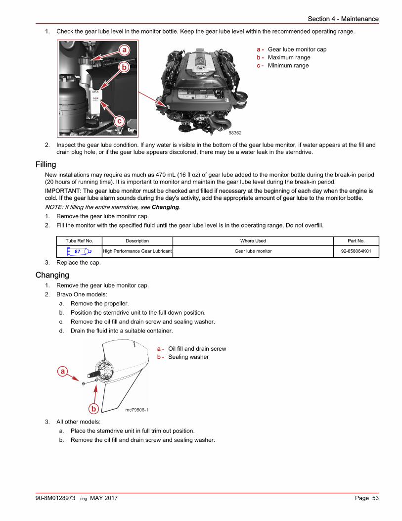
1. Check the gear lube level in the monitor bottle. Keep the gear lube level within the recommended operating range.
a - Gear lube monitor capb - Maximum rangec - Minimum range
2. Inspect the gear lube condition. If any water is visible in the bottom of the gear lube monitor, if water appears at the fill anddrain plug hole, or if the gear lube appears discolored, there may be a water leak in the sterndrive.
FillingNew installations may require as much as 470 mL (16 fl oz) of gear lube added to the monitor bottle during the break‑in period(20 hours of running time). It is important to monitor and maintain the gear lube level during the break‑in period.IMPORTANT: The gear lube monitor must be checked and filled if necessary at the beginning of each day when the engine iscold. If the gear lube alarm sounds during the day's activity, add the appropriate amount of gear lube to the monitor bottle.NOTE: If filling the entire sterndrive, see Changing.1. Remove the gear lube monitor cap.2. Fill the monitor with the specified fluid until the gear lube level is in the operating range. Do not overfill.
Tube Ref No. Description Where Used Part No.
87 High Performance Gear Lubricant Gear lube monitor 92-858064K01
3. Replace the cap.
Changing1. Remove the gear lube monitor cap.2. Bravo One models:
a. Remove the propeller.b. Position the sterndrive unit to the full down position.c. Remove the oil fill and drain screw and sealing washer.d. Drain the fluid into a suitable container.
a - Oil fill and drain screwb - Sealing washer
3. All other models:a. Place the sterndrive unit in full trim out position.b. Remove the oil fill and drain screw and sealing washer.
MAX
MIN
b
c
a
58362
a
b mc79506-1
Section 4 - Maintenance
90-8M0128973 eng MAY 2017 Page 53
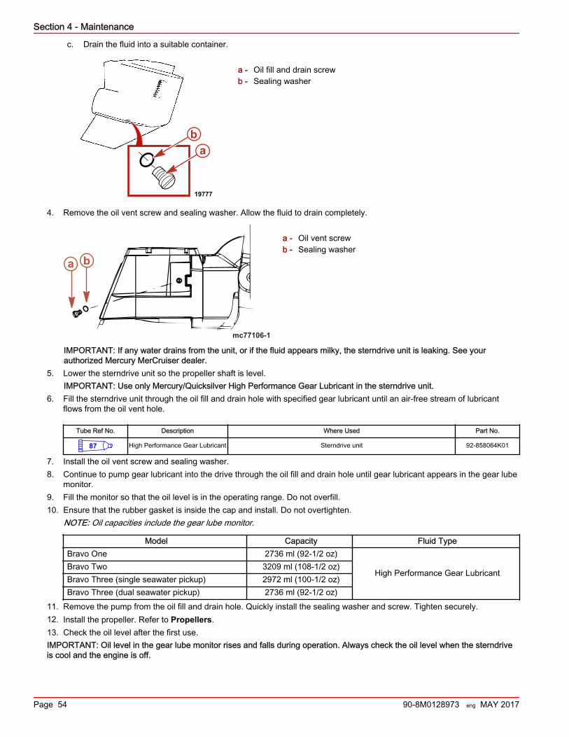
c. Drain the fluid into a suitable container.
a - Oil fill and drain screwb - Sealing washer
4. Remove the oil vent screw and sealing washer. Allow the fluid to drain completely.
a - Oil vent screwb - Sealing washer
IMPORTANT: If any water drains from the unit, or if the fluid appears milky, the sterndrive unit is leaking. See yourauthorized Mercury MerCruiser dealer.
5. Lower the sterndrive unit so the propeller shaft is level.IMPORTANT: Use only Mercury/Quicksilver High Performance Gear Lubricant in the sterndrive unit.
6. Fill the sterndrive unit through the oil fill and drain hole with specified gear lubricant until an air‑free stream of lubricantflows from the oil vent hole.
Tube Ref No. Description Where Used Part No.
87 High Performance Gear Lubricant Sterndrive unit 92-858064K01
7. Install the oil vent screw and sealing washer.8. Continue to pump gear lubricant into the drive through the oil fill and drain hole until gear lubricant appears in the gear lube
monitor.9. Fill the monitor so that the oil level is in the operating range. Do not overfill.10. Ensure that the rubber gasket is inside the cap and install. Do not overtighten.
NOTE: Oil capacities include the gear lube monitor.
Model Capacity Fluid TypeBravo One 2736 ml (92‑1/2 oz)
High Performance Gear LubricantBravo Two 3209 ml (108‑1/2 oz)Bravo Three (single seawater pickup) 2972 ml (100‑1/2 oz)Bravo Three (dual seawater pickup) 2736 ml (92‑1/2 oz)
11. Remove the pump from the oil fill and drain hole. Quickly install the sealing washer and screw. Tighten securely.12. Install the propeller. Refer to Propellers.13. Check the oil level after the first use.IMPORTANT: Oil level in the gear lube monitor rises and falls during operation. Always check the oil level when the sterndriveis cool and the engine is off.
ab
19777
mc77106-1
ba
Section 4 - Maintenance
Page 54 90-8M0128973 eng MAY 2017
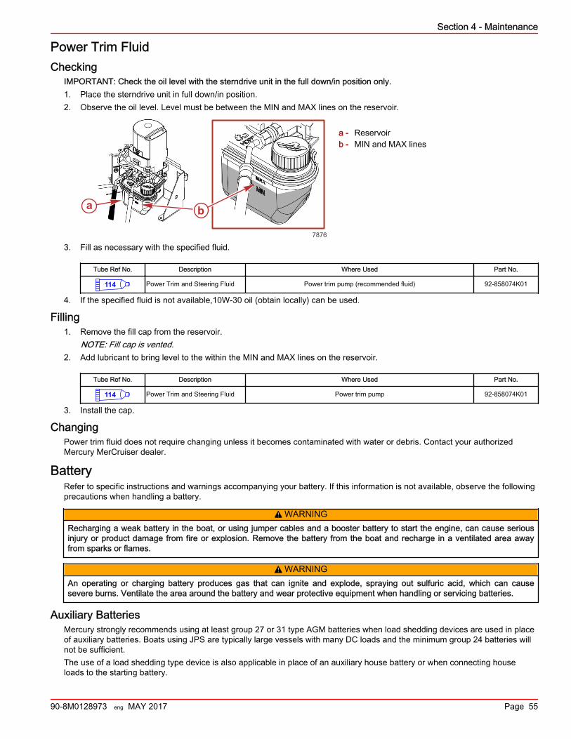
Power Trim FluidChecking
IMPORTANT: Check the oil level with the sterndrive unit in the full down/in position only.1. Place the sterndrive unit in full down/in position.2. Observe the oil level. Level must be between the MIN and MAX lines on the reservoir.
a - Reservoirb - MIN and MAX lines
3. Fill as necessary with the specified fluid.
Tube Ref No. Description Where Used Part No.
114 Power Trim and Steering Fluid Power trim pump (recommended fluid) 92-858074K01
4. If the specified fluid is not available,10W‑30 oil (obtain locally) can be used.
Filling1. Remove the fill cap from the reservoir.
NOTE: Fill cap is vented.2. Add lubricant to bring level to the within the MIN and MAX lines on the reservoir.
Tube Ref No. Description Where Used Part No.
114 Power Trim and Steering Fluid Power trim pump 92-858074K01
3. Install the cap.
ChangingPower trim fluid does not require changing unless it becomes contaminated with water or debris. Contact your authorizedMercury MerCruiser dealer.
BatteryRefer to specific instructions and warnings accompanying your battery. If this information is not available, observe the followingprecautions when handling a battery.
! WARNINGRecharging a weak battery in the boat, or using jumper cables and a booster battery to start the engine, can cause seriousinjury or product damage from fire or explosion. Remove the battery from the boat and recharge in a ventilated area awayfrom sparks or flames.
! WARNINGAn operating or charging battery produces gas that can ignite and explode, spraying out sulfuric acid, which can causesevere burns. Ventilate the area around the battery and wear protective equipment when handling or servicing batteries.
Auxiliary BatteriesMercury strongly recommends using at least group 27 or 31 type AGM batteries when load shedding devices are used in placeof auxiliary batteries. Boats using JPS are typically large vessels with many DC loads and the minimum group 24 batteries willnot be sufficient.The use of a load shedding type device is also applicable in place of an auxiliary house battery or when connecting houseloads to the starting battery.
a bb
7876
Section 4 - Maintenance
90-8M0128973 eng MAY 2017 Page 55
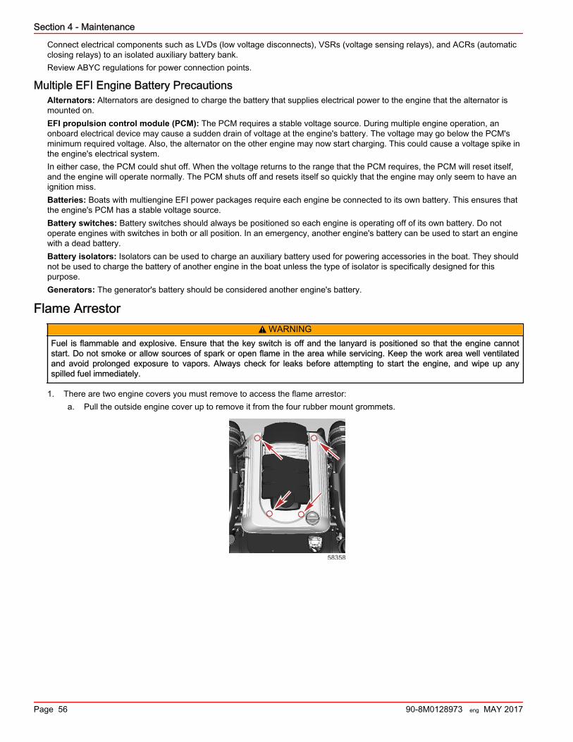
Connect electrical components such as LVDs (low voltage disconnects), VSRs (voltage sensing relays), and ACRs (automaticclosing relays) to an isolated auxiliary battery bank.Review ABYC regulations for power connection points.
Multiple EFI Engine Battery PrecautionsAlternators: Alternators are designed to charge the battery that supplies electrical power to the engine that the alternator ismounted on.EFI propulsion control module (PCM): The PCM requires a stable voltage source. During multiple engine operation, anonboard electrical device may cause a sudden drain of voltage at the engine's battery. The voltage may go below the PCM'sminimum required voltage. Also, the alternator on the other engine may now start charging. This could cause a voltage spike inthe engine's electrical system.In either case, the PCM could shut off. When the voltage returns to the range that the PCM requires, the PCM will reset itself,and the engine will operate normally. The PCM shuts off and resets itself so quickly that the engine may only seem to have anignition miss.Batteries: Boats with multiengine EFI power packages require each engine be connected to its own battery. This ensures thatthe engine's PCM has a stable voltage source.Battery switches: Battery switches should always be positioned so each engine is operating off of its own battery. Do notoperate engines with switches in both or all position. In an emergency, another engine's battery can be used to start an enginewith a dead battery.Battery isolators: Isolators can be used to charge an auxiliary battery used for powering accessories in the boat. They shouldnot be used to charge the battery of another engine in the boat unless the type of isolator is specifically designed for thispurpose.Generators: The generator's battery should be considered another engine's battery.
Flame Arrestor! WARNING
Fuel is flammable and explosive. Ensure that the key switch is off and the lanyard is positioned so that the engine cannotstart. Do not smoke or allow sources of spark or open flame in the area while servicing. Keep the work area well ventilatedand avoid prolonged exposure to vapors. Always check for leaks before attempting to start the engine, and wipe up anyspilled fuel immediately.
1. There are two engine covers you must remove to access the flame arrestor:a. Pull the outside engine cover up to remove it from the four rubber mount grommets.
58358
Section 4 - Maintenance
Page 56 90-8M0128973 eng MAY 2017
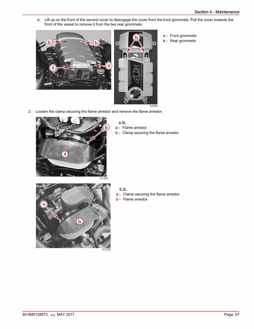
b. Lift up on the front of the second cover to disengage the cover from the front grommets. Pull the cover towards thefront of the vessel to remove it from the two rear grommets.
a - Front grommetsb - Rear grommets
2. Loosen the clamp securing the flame arrestor and remove the flame arrestor.
4.5La - Flame arrestorb - Clamp securing the flame arrestor
6.2La - Clamp securing the flame arrestorb - Flame arrestor
a a
b bb
54984
a
b
61358
61328
a
b
Section 4 - Maintenance
90-8M0128973 eng MAY 2017 Page 57
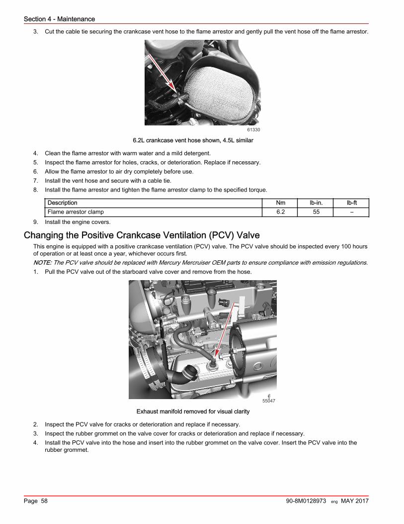
3. Cut the cable tie securing the crankcase vent hose to the flame arrestor and gently pull the vent hose off the flame arrestor.
61330
6.2L crankcase vent hose shown, 4.5L similar
4. Clean the flame arrestor with warm water and a mild detergent.5. Inspect the flame arrestor for holes, cracks, or deterioration. Replace if necessary.6. Allow the flame arrestor to air dry completely before use.7. Install the vent hose and secure with a cable tie.8. Install the flame arrestor and tighten the flame arrestor clamp to the specified torque.
Description Nm lb‑in. lb‑ftFlame arrestor clamp 6.2 55 –
9. Install the engine covers.
Changing the Positive Crankcase Ventilation (PCV) ValveThis engine is equipped with a positive crankcase ventilation (PCV) valve. The PCV valve should be inspected every 100 hoursof operation or at least once a year, whichever occurs first.NOTE: The PCV valve should be replaced with Mercury Mercruiser OEM parts to ensure compliance with emission regulations.1. Pull the PCV valve out of the starboard valve cover and remove from the hose.
55047
Exhaust manifold removed for visual clarity
2. Inspect the PCV valve for cracks or deterioration and replace if necessary.3. Inspect the rubber grommet on the valve cover for cracks or deterioration and replace if necessary.4. Install the PCV valve into the hose and insert into the rubber grommet on the valve cover. Insert the PCV valve into the
rubber grommet.
Section 4 - Maintenance
Page 58 90-8M0128973 eng MAY 2017
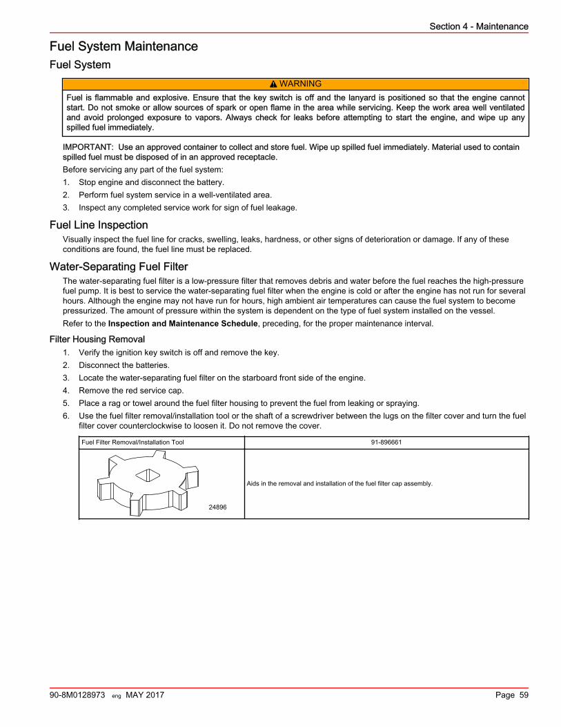
Fuel System MaintenanceFuel System
! WARNINGFuel is flammable and explosive. Ensure that the key switch is off and the lanyard is positioned so that the engine cannotstart. Do not smoke or allow sources of spark or open flame in the area while servicing. Keep the work area well ventilatedand avoid prolonged exposure to vapors. Always check for leaks before attempting to start the engine, and wipe up anyspilled fuel immediately.
IMPORTANT: Use an approved container to collect and store fuel. Wipe up spilled fuel immediately. Material used to containspilled fuel must be disposed of in an approved receptacle.Before servicing any part of the fuel system:1. Stop engine and disconnect the battery.2. Perform fuel system service in a well‑ventilated area.3. Inspect any completed service work for sign of fuel leakage.
Fuel Line InspectionVisually inspect the fuel line for cracks, swelling, leaks, hardness, or other signs of deterioration or damage. If any of theseconditions are found, the fuel line must be replaced.
Water‑Separating Fuel FilterThe water‑separating fuel filter is a low‑pressure filter that removes debris and water before the fuel reaches the high‑pressurefuel pump. It is best to service the water‑separating fuel filter when the engine is cold or after the engine has not run for severalhours. Although the engine may not have run for hours, high ambient air temperatures can cause the fuel system to becomepressurized. The amount of pressure within the system is dependent on the type of fuel system installed on the vessel.Refer to the Inspection and Maintenance Schedule, preceding, for the proper maintenance interval.
Filter Housing Removal1. Verify the ignition key switch is off and remove the key.2. Disconnect the batteries.3. Locate the water‑separating fuel filter on the starboard front side of the engine.4. Remove the red service cap.5. Place a rag or towel around the fuel filter housing to prevent the fuel from leaking or spraying.6. Use the fuel filter removal/installation tool or the shaft of a screwdriver between the lugs on the filter cover and turn the fuel
filter cover counterclockwise to loosen it. Do not remove the cover.
Fuel Filter Removal/Installation Tool 91‑896661
24896
Aids in the removal and installation of the fuel filter cap assembly.
Section 4 - Maintenance
90-8M0128973 eng MAY 2017 Page 59
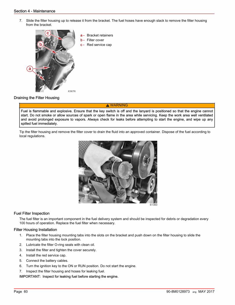
7. Slide the filter housing up to release it from the bracket. The fuel hoses have enough slack to remove the filter housingfrom the bracket.
a - Bracket retainersb - Filter coverc - Red service cap
Draining the Filter Housing
! WARNINGFuel is flammable and explosive. Ensure that the key switch is off and the lanyard is positioned so that the engine cannotstart. Do not smoke or allow sources of spark or open flame in the area while servicing. Keep the work area well ventilatedand avoid prolonged exposure to vapors. Always check for leaks before attempting to start the engine, and wipe up anyspilled fuel immediately.
Tip the filter housing and remove the filter cover to drain the fluid into an approved container. Dispose of the fuel according tolocal regulations.
61360
Fuel Filter InspectionThe fuel filter is an important component in the fuel delivery system and should be inspected for debris or degradation every100 hours of operation. Replace the fuel filter when necessary.
Filter Housing Installation1. Place the filter housing mounting tabs into the slots on the bracket and push down on the filter housing to slide the
mounting tabs into the lock position.2. Lubricate the filter O‑ring seals with clean oil.3. Install the filter and tighten the cover securely.4. Install the red service cap.5. Connect the battery cables.6. Turn the ignition key to the ON or RUN position. Do not start the engine.7. Inspect the filter housing and hoses for leaking fuel.IMPORTANT: Inspect for leaking fuel before starting the engine.
b
c
a
63676
Section 4 - Maintenance
Page 60 90-8M0128973 eng MAY 2017
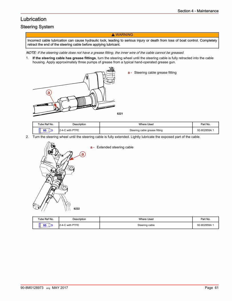
LubricationSteering System
! WARNINGIncorrect cable lubrication can cause hydraulic lock, leading to serious injury or death from loss of boat control. Completelyretract the end of the steering cable before applying lubricant.
NOTE: If the steering cable does not have a grease fitting, the inner wire of the cable cannot be greased.1. If the steering cable has grease fittings, turn the steering wheel until the steering cable is fully retracted into the cable
housing. Apply approximately three pumps of grease from a typical hand‑operated grease gun.
a - Steering cable grease fitting
Tube Ref No. Description Where Used Part No.
95 2-4-C with PTFE Steering cable grease fitting 92-802859A 1
2. Turn the steering wheel until the steering cable is fully extended. Lightly lubricate the exposed part of the cable.
a - Extended steering cable
Tube Ref No. Description Where Used Part No.
95 2-4-C with PTFE Steering cable 92-802859A 1
6221
a
a
6222
Section 4 - Maintenance
90-8M0128973 eng MAY 2017 Page 61
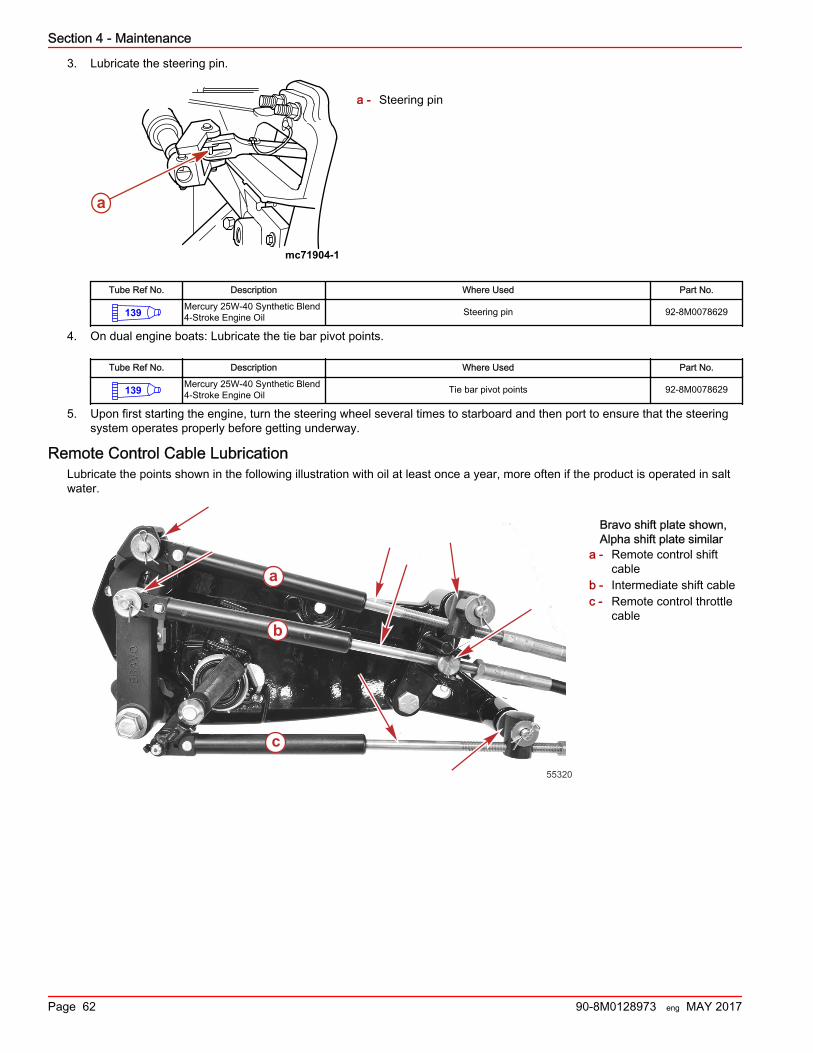
3. Lubricate the steering pin.
a - Steering pin
Tube Ref No. Description Where Used Part No.
139 Mercury 25W-40 Synthetic Blend4-Stroke Engine Oil Steering pin 92-8M0078629
4. On dual engine boats: Lubricate the tie bar pivot points.
Tube Ref No. Description Where Used Part No.
139 Mercury 25W-40 Synthetic Blend4-Stroke Engine Oil Tie bar pivot points 92-8M0078629
5. Upon first starting the engine, turn the steering wheel several times to starboard and then port to ensure that the steeringsystem operates properly before getting underway.
Remote Control Cable LubricationLubricate the points shown in the following illustration with oil at least once a year, more often if the product is operated in saltwater.
Bravo shift plate shown,Alpha shift plate similar
a - Remote control shiftcable
b - Intermediate shift cablec - Remote control throttle
cable
mc71904-1
a
55320
a
b
c
Section 4 - Maintenance
Page 62 90-8M0128973 eng MAY 2017
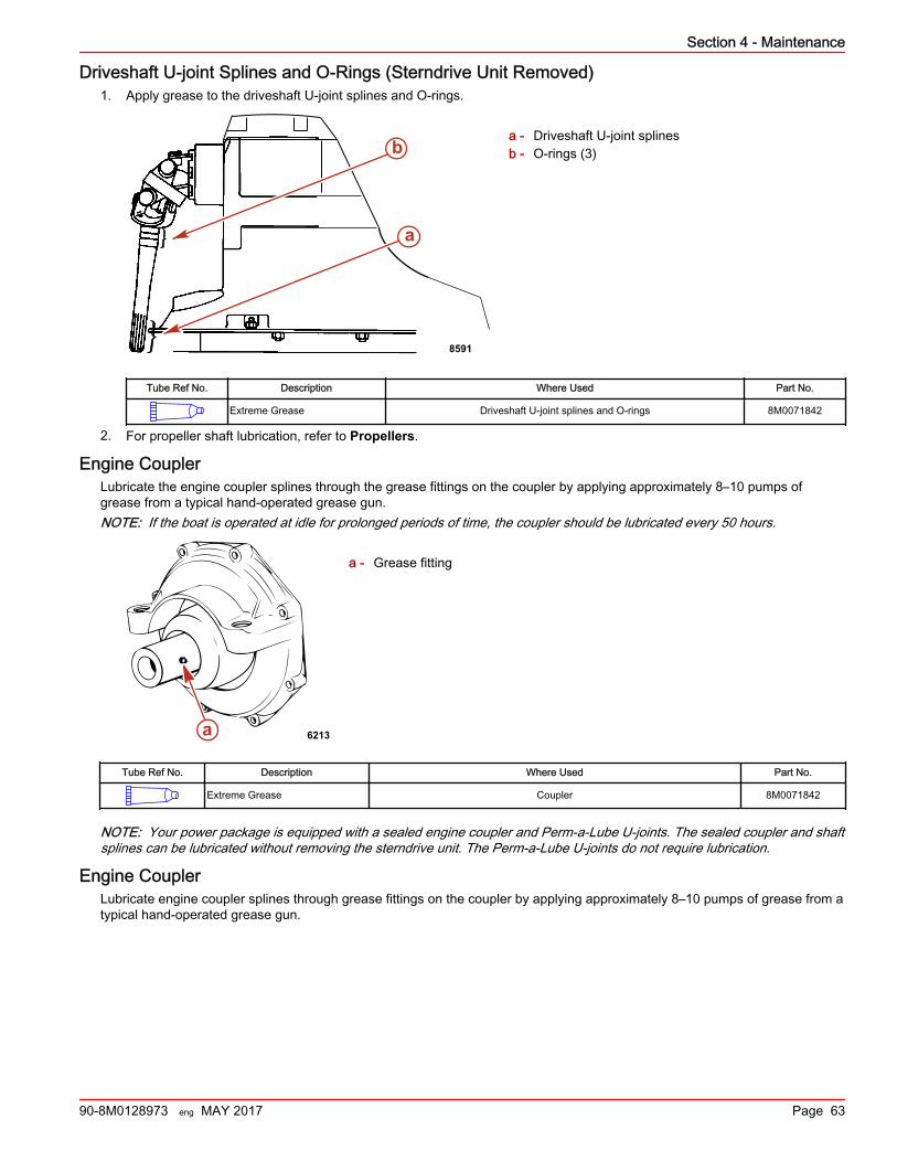
Driveshaft U‑joint Splines and O‑Rings (Sterndrive Unit Removed)1. Apply grease to the driveshaft U‑joint splines and O‑rings.
a - Driveshaft U‑joint splinesb - O‑rings (3)
Tube Ref No. Description Where Used Part No.
Extreme Grease Driveshaft U-joint splines and O-rings 8M0071842
2. For propeller shaft lubrication, refer to Propellers.
Engine CouplerLubricate the engine coupler splines through the grease fittings on the coupler by applying approximately 8–10 pumps ofgrease from a typical hand‑operated grease gun.NOTE: If the boat is operated at idle for prolonged periods of time, the coupler should be lubricated every 50 hours.
a - Grease fitting
Tube Ref No. Description Where Used Part No.
Extreme Grease Coupler 8M0071842
NOTE: Your power package is equipped with a sealed engine coupler and Perm‑a‑Lube U‑joints. The sealed coupler and shaftsplines can be lubricated without removing the sterndrive unit. The Perm‑a‑Lube U‑joints do not require lubrication.
Engine CouplerLubricate engine coupler splines through grease fittings on the coupler by applying approximately 8–10 pumps of grease from atypical hand‑operated grease gun.
b
a
8591
a 6213
Section 4 - Maintenance
90-8M0128973 eng MAY 2017 Page 63
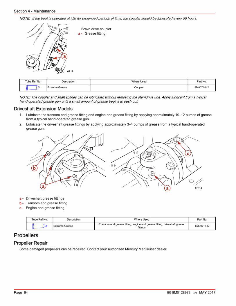
NOTE: If the boat is operated at idle for prolonged periods of time, the coupler should be lubricated every 50 hours.
Bravo drive couplera - Grease fitting
Tube Ref No. Description Where Used Part No.
Extreme Grease Coupler 8M0071842
NOTE: The coupler and shaft splines can be lubricated without removing the sterndrive unit. Apply lubricant from a typicalhand‑operated grease gun until a small amount of grease begins to push out.
Driveshaft Extension Models1. Lubricate the transom end grease fitting and engine end grease fitting by applying approximately 10–12 pumps of grease
from a typical hand‑operated grease gun.2. Lubricate the driveshaft grease fittings by applying approximately 3–4 pumps of grease from a typical hand‑operated
grease gun.
a - Driveshaft grease fittingsb - Transom end grease fittingc - Engine end grease fitting
Tube Ref No. Description Where Used Part No.
Extreme Grease Transom end grease fitting, engine end grease fitting, driveshaft greasefittings 8M0071842
PropellersPropeller Repair
Some damaged propellers can be repaired. Contact your authorized Mercury MerCruiser dealer.
a
6212
a
b
a
c
17014
Section 4 - Maintenance
Page 64 90-8M0128973 eng MAY 2017
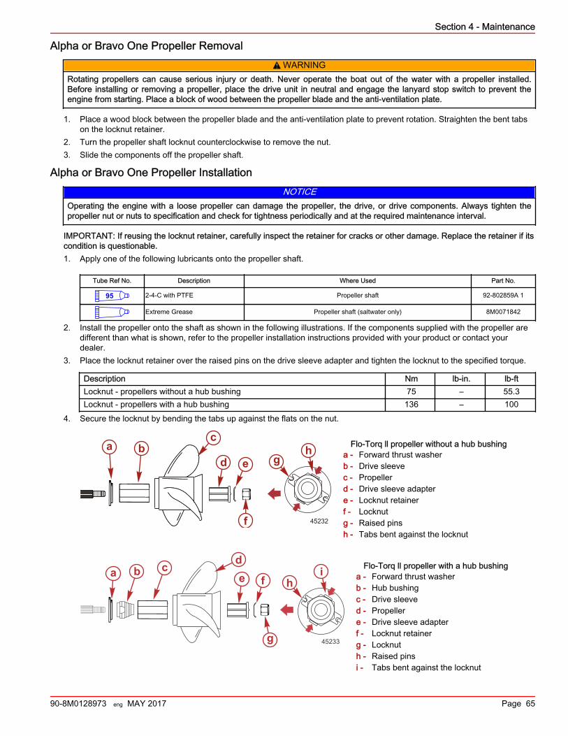
Alpha or Bravo One Propeller Removal! WARNING
Rotating propellers can cause serious injury or death. Never operate the boat out of the water with a propeller installed.Before installing or removing a propeller, place the drive unit in neutral and engage the lanyard stop switch to prevent theengine from starting. Place a block of wood between the propeller blade and the anti‑ventilation plate.
1. Place a wood block between the propeller blade and the anti‑ventilation plate to prevent rotation. Straighten the bent tabson the locknut retainer.
2. Turn the propeller shaft locknut counterclockwise to remove the nut.3. Slide the components off the propeller shaft.
Alpha or Bravo One Propeller InstallationNOTICE
Operating the engine with a loose propeller can damage the propeller, the drive, or drive components. Always tighten thepropeller nut or nuts to specification and check for tightness periodically and at the required maintenance interval.
IMPORTANT: If reusing the locknut retainer, carefully inspect the retainer for cracks or other damage. Replace the retainer if itscondition is questionable.1. Apply one of the following lubricants onto the propeller shaft.
Tube Ref No. Description Where Used Part No.
95 2-4-C with PTFE Propeller shaft 92-802859A 1
Extreme Grease Propeller shaft (saltwater only) 8M0071842
2. Install the propeller onto the shaft as shown in the following illustrations. If the components supplied with the propeller aredifferent than what is shown, refer to the propeller installation instructions provided with your product or contact yourdealer.
3. Place the locknut retainer over the raised pins on the drive sleeve adapter and tighten the locknut to the specified torque.
Description Nm lb‑in. lb‑ftLocknut ‑ propellers without a hub bushing 75 – 55.3Locknut ‑ propellers with a hub bushing 136 – 100
4. Secure the locknut by bending the tabs up against the flats on the nut.
Flo-Torq ll propeller without a hub bushinga - Forward thrust washerb - Drive sleevec - Propellerd - Drive sleeve adaptere - Locknut retainerf - Locknutg - Raised pinsh - Tabs bent against the locknut
Flo-Torq ll propeller with a hub bushinga - Forward thrust washerb - Hub bushingc - Drive sleeved - Propellere - Drive sleeve adapterf - Locknut retainerg - Locknuth - Raised pinsi - Tabs bent against the locknut
45232
c
d e
f
a bg
h
45233
a b c de f
g
hi
Section 4 - Maintenance
90-8M0128973 eng MAY 2017 Page 65
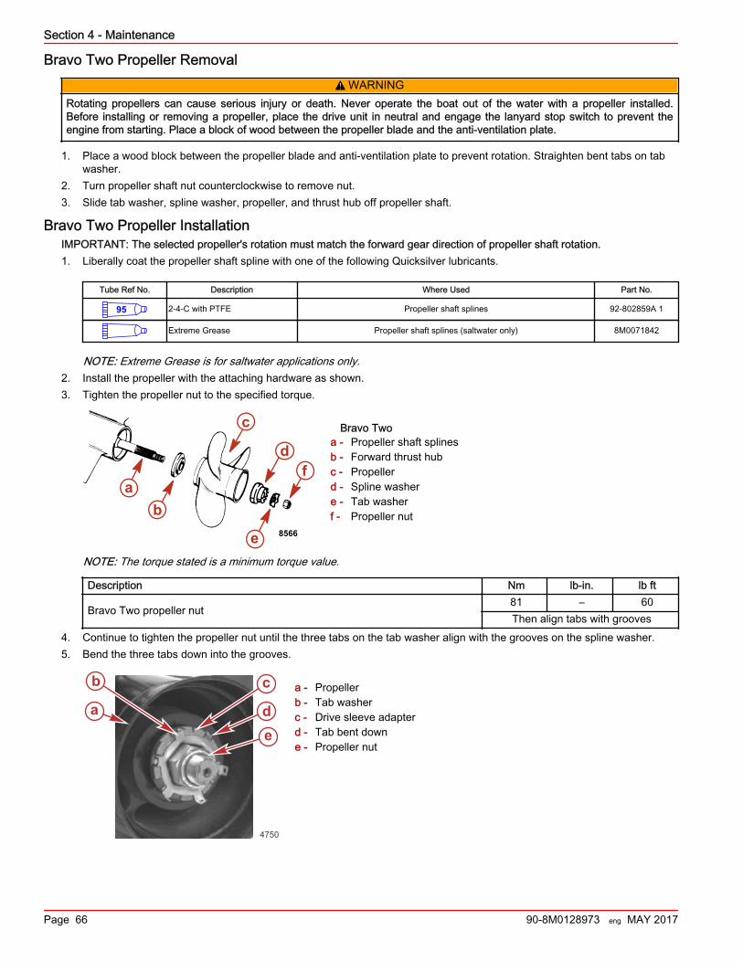
Bravo Two Propeller Removal! WARNING
Rotating propellers can cause serious injury or death. Never operate the boat out of the water with a propeller installed.Before installing or removing a propeller, place the drive unit in neutral and engage the lanyard stop switch to prevent theengine from starting. Place a block of wood between the propeller blade and the anti‑ventilation plate.
1. Place a wood block between the propeller blade and anti‑ventilation plate to prevent rotation. Straighten bent tabs on tabwasher.
2. Turn propeller shaft nut counterclockwise to remove nut.3. Slide tab washer, spline washer, propeller, and thrust hub off propeller shaft.
Bravo Two Propeller InstallationIMPORTANT: The selected propeller's rotation must match the forward gear direction of propeller shaft rotation.1. Liberally coat the propeller shaft spline with one of the following Quicksilver lubricants.
Tube Ref No. Description Where Used Part No.
95 2-4-C with PTFE Propeller shaft splines 92-802859A 1
Extreme Grease Propeller shaft splines (saltwater only) 8M0071842
NOTE: Extreme Grease is for saltwater applications only.2. Install the propeller with the attaching hardware as shown.3. Tighten the propeller nut to the specified torque.
Bravo Twoa - Propeller shaft splinesb - Forward thrust hubc - Propellerd - Spline washere - Tab washerf - Propeller nut
NOTE: The torque stated is a minimum torque value.
Description Nm lb‑in. lb ft
Bravo Two propeller nut81 – 60Then align tabs with grooves
4. Continue to tighten the propeller nut until the three tabs on the tab washer align with the grooves on the spline washer.5. Bend the three tabs down into the grooves.
a - Propellerb - Tab washerc - Drive sleeve adapterd - Tab bent downe - Propeller nut
8566
ab
c
fd
e
a
b c
de
4750
Section 4 - Maintenance
Page 66 90-8M0128973 eng MAY 2017
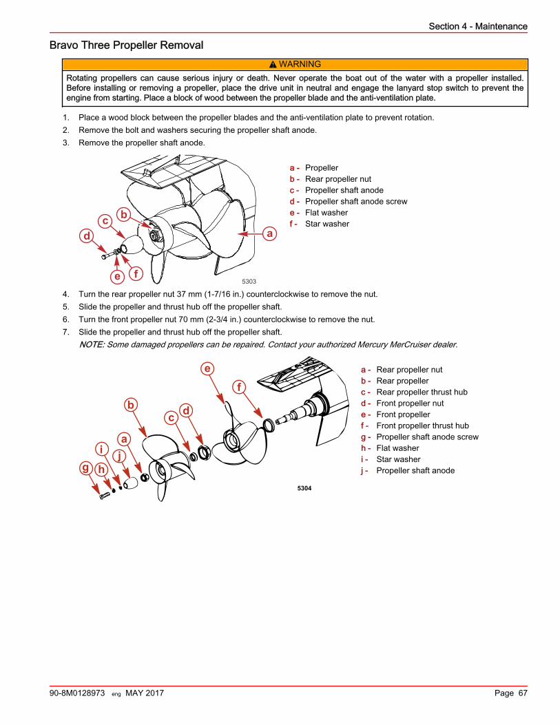
Bravo Three Propeller Removal! WARNING
Rotating propellers can cause serious injury or death. Never operate the boat out of the water with a propeller installed.Before installing or removing a propeller, place the drive unit in neutral and engage the lanyard stop switch to prevent theengine from starting. Place a block of wood between the propeller blade and the anti‑ventilation plate.
1. Place a wood block between the propeller blades and the anti‑ventilation plate to prevent rotation.2. Remove the bolt and washers securing the propeller shaft anode.3. Remove the propeller shaft anode.
a - Propellerb - Rear propeller nutc - Propeller shaft anoded - Propeller shaft anode screwe - Flat washerf - Star washer
4. Turn the rear propeller nut 37 mm (1‑7/16 in.) counterclockwise to remove the nut.5. Slide the propeller and thrust hub off the propeller shaft.6. Turn the front propeller nut 70 mm (2‑3/4 in.) counterclockwise to remove the nut.7. Slide the propeller and thrust hub off the propeller shaft.
NOTE: Some damaged propellers can be repaired. Contact your authorized Mercury MerCruiser dealer.
a - Rear propeller nutb - Rear propellerc - Rear propeller thrust hubd - Front propeller nute - Front propellerf - Front propeller thrust hubg - Propeller shaft anode screwh - Flat washeri - Star washerj - Propeller shaft anode
5303
abc
d
e f
ef
a
bc d
5304
g h
i j
Section 4 - Maintenance
90-8M0128973 eng MAY 2017 Page 67
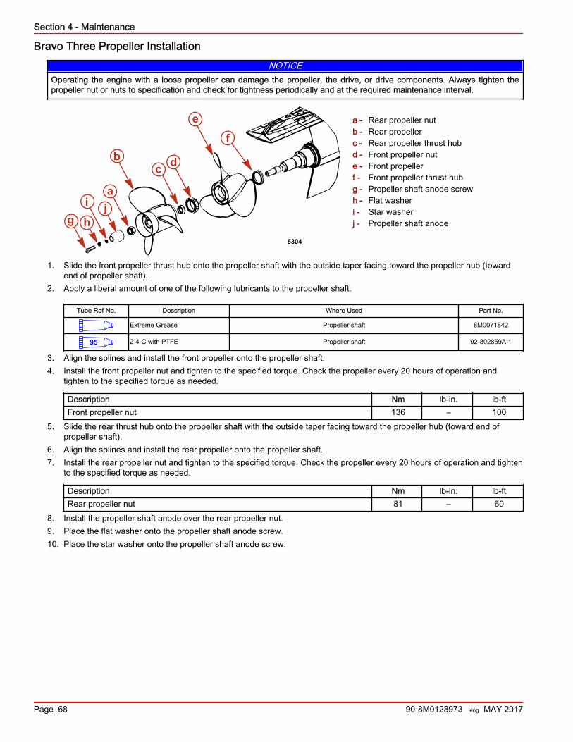
Bravo Three Propeller InstallationNOTICE
Operating the engine with a loose propeller can damage the propeller, the drive, or drive components. Always tighten thepropeller nut or nuts to specification and check for tightness periodically and at the required maintenance interval.
a - Rear propeller nutb - Rear propellerc - Rear propeller thrust hubd - Front propeller nute - Front propellerf - Front propeller thrust hubg - Propeller shaft anode screwh - Flat washeri - Star washerj - Propeller shaft anode
1. Slide the front propeller thrust hub onto the propeller shaft with the outside taper facing toward the propeller hub (towardend of propeller shaft).
2. Apply a liberal amount of one of the following lubricants to the propeller shaft.
Tube Ref No. Description Where Used Part No.
Extreme Grease Propeller shaft 8M0071842
95 2-4-C with PTFE Propeller shaft 92-802859A 1
3. Align the splines and install the front propeller onto the propeller shaft.4. Install the front propeller nut and tighten to the specified torque. Check the propeller every 20 hours of operation and
tighten to the specified torque as needed.
Description Nm lb‑in. lb‑ftFront propeller nut 136 – 100
5. Slide the rear thrust hub onto the propeller shaft with the outside taper facing toward the propeller hub (toward end ofpropeller shaft).
6. Align the splines and install the rear propeller onto the propeller shaft.7. Install the rear propeller nut and tighten to the specified torque. Check the propeller every 20 hours of operation and tighten
to the specified torque as needed.
Description Nm lb‑in. lb‑ftRear propeller nut 81 – 60
8. Install the propeller shaft anode over the rear propeller nut.9. Place the flat washer onto the propeller shaft anode screw.10. Place the star washer onto the propeller shaft anode screw.
ef
a
bc d
5304
g h
i j
Section 4 - Maintenance
Page 68 90-8M0128973 eng MAY 2017
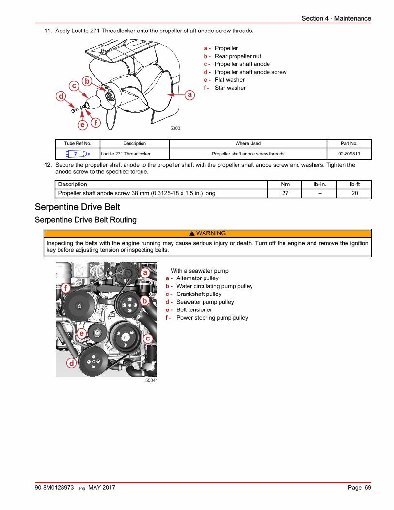
11. Apply Loctite 271 Threadlocker onto the propeller shaft anode screw threads.
a - Propellerb - Rear propeller nutc - Propeller shaft anoded - Propeller shaft anode screwe - Flat washerf - Star washer
Tube Ref No. Description Where Used Part No.
7 Loctite 271 Threadlocker Propeller shaft anode screw threads 92-809819
12. Secure the propeller shaft anode to the propeller shaft with the propeller shaft anode screw and washers. Tighten theanode screw to the specified torque.
Description Nm lb‑in. lb‑ftPropeller shaft anode screw 38 mm (0.3125‑18 x 1.5 in.) long 27 – 20
Serpentine Drive BeltSerpentine Drive Belt Routing
! WARNINGInspecting the belts with the engine running may cause serious injury or death. Turn off the engine and remove the ignitionkey before adjusting tension or inspecting belts.
With a seawater pumpa - Alternator pulleyb - Water circulating pump pulleyc - Crankshaft pulleyd - Seawater pump pulleye - Belt tensionerf - Power steering pump pulley
5303
abc
d
e f
a
b
c
d
e
f
55041
Section 4 - Maintenance
90-8M0128973 eng MAY 2017 Page 69
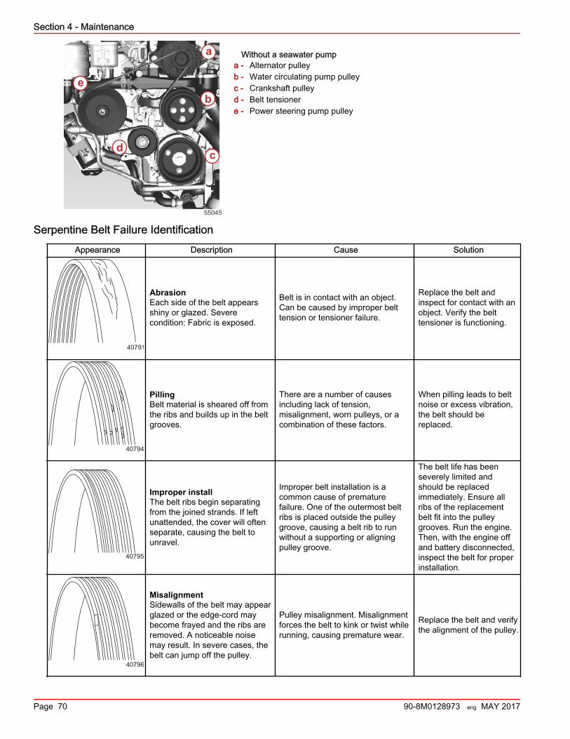
Without a seawater pumpa - Alternator pulleyb - Water circulating pump pulleyc - Crankshaft pulleyd - Belt tensionere - Power steering pump pulley
Serpentine Belt Failure Identification
Appearance Description Cause Solution
40791
AbrasionEach side of the belt appearsshiny or glazed. Severecondition: Fabric is exposed.
Belt is in contact with an object.Can be caused by improper belttension or tensioner failure.
Replace the belt andinspect for contact with anobject. Verify the belttensioner is functioning.
40794
PillingBelt material is sheared off fromthe ribs and builds up in the beltgrooves.
There are a number of causesincluding lack of tension,misalignment, worn pulleys, or acombination of these factors.
When pilling leads to beltnoise or excess vibration,the belt should bereplaced.
40795
Improper installThe belt ribs begin separatingfrom the joined strands. If leftunattended, the cover will oftenseparate, causing the belt tounravel.
Improper belt installation is acommon cause of prematurefailure. One of the outermost beltribs is placed outside the pulleygroove, causing a belt rib to runwithout a supporting or aligningpulley groove.
The belt life has beenseverely limited andshould be replacedimmediately. Ensure allribs of the replacementbelt fit into the pulleygrooves. Run the engine.Then, with the engine offand battery disconnected,inspect the belt for properinstallation.
40796
MisalignmentSidewalls of the belt may appearglazed or the edge‑cord maybecome frayed and the ribs areremoved. A noticeable noisemay result. In severe cases, thebelt can jump off the pulley.
Pulley misalignment. Misalignmentforces the belt to kink or twist whilerunning, causing premature wear.
Replace the belt and verifythe alignment of the pulley.
a
b
cd
e
55045
Section 4 - Maintenance
Page 70 90-8M0128973 eng MAY 2017
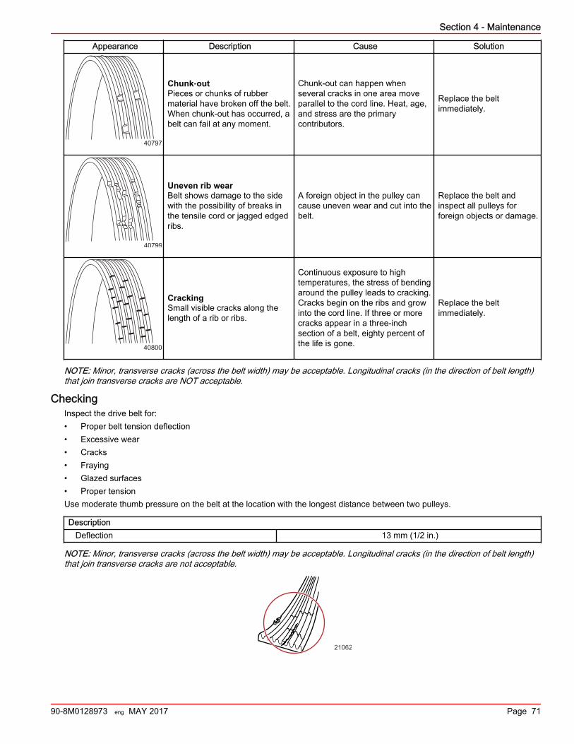
Appearance Description Cause Solution
40797
Chunk‑outPieces or chunks of rubbermaterial have broken off the belt.When chunk‑out has occurred, abelt can fail at any moment.
Chunk‑out can happen whenseveral cracks in one area moveparallel to the cord line. Heat, age,and stress are the primarycontributors.
Replace the beltimmediately.
40799
Uneven rib wearBelt shows damage to the sidewith the possibility of breaks inthe tensile cord or jagged edgedribs.
A foreign object in the pulley cancause uneven wear and cut into thebelt.
Replace the belt andinspect all pulleys forforeign objects or damage.
40800
CrackingSmall visible cracks along thelength of a rib or ribs.
Continuous exposure to hightemperatures, the stress of bendingaround the pulley leads to cracking.Cracks begin on the ribs and growinto the cord line. If three or morecracks appear in a three‑inchsection of a belt, eighty percent ofthe life is gone.
Replace the beltimmediately.
NOTE: Minor, transverse cracks (across the belt width) may be acceptable. Longitudinal cracks (in the direction of belt length)that join transverse cracks are NOT acceptable.
CheckingInspect the drive belt for:• Proper belt tension deflection• Excessive wear• Cracks• Fraying• Glazed surfaces• Proper tensionUse moderate thumb pressure on the belt at the location with the longest distance between two pulleys.
Description Deflection 13 mm (1/2 in.)
NOTE: Minor, transverse cracks (across the belt width) may be acceptable. Longitudinal cracks (in the direction of belt length)that join transverse cracks are not acceptable.
21062
Section 4 - Maintenance
90-8M0128973 eng MAY 2017 Page 71
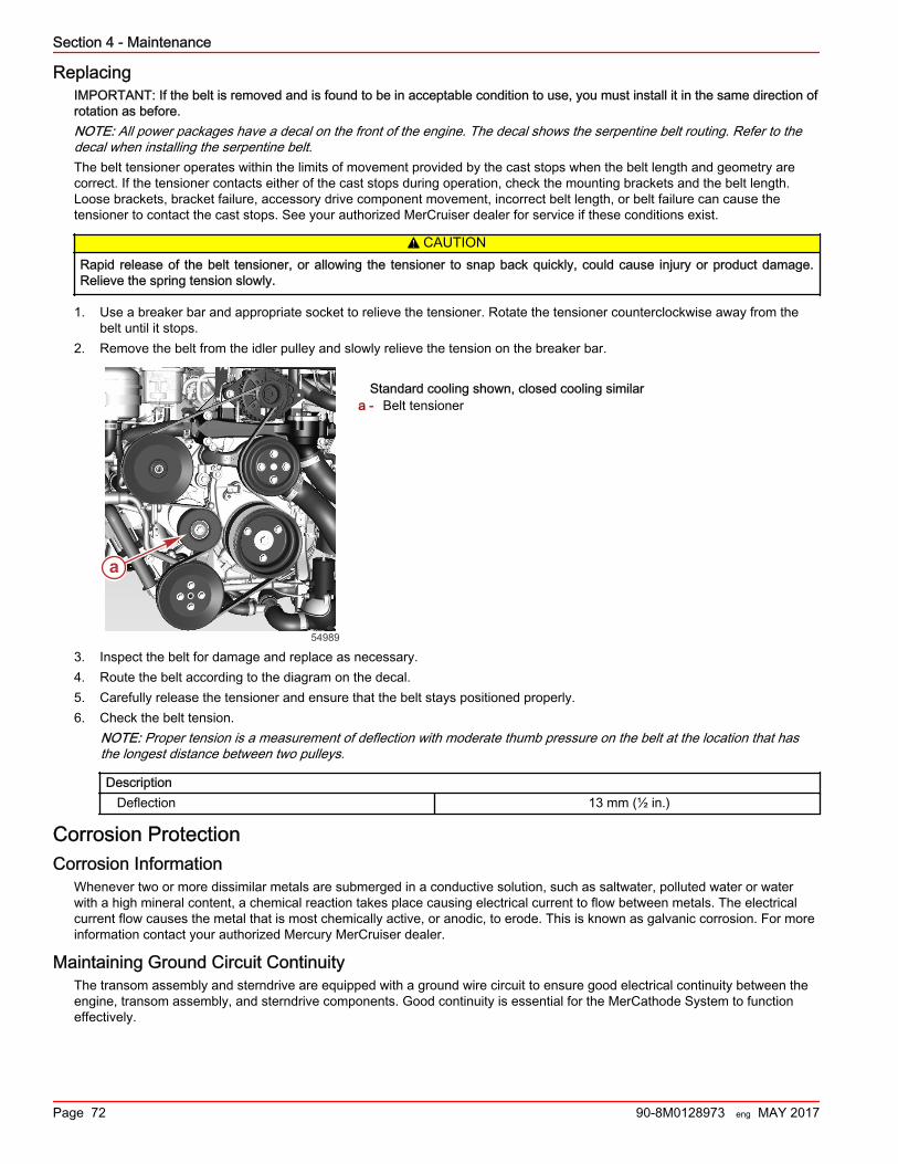
ReplacingIMPORTANT: If the belt is removed and is found to be in acceptable condition to use, you must install it in the same direction ofrotation as before.NOTE: All power packages have a decal on the front of the engine. The decal shows the serpentine belt routing. Refer to thedecal when installing the serpentine belt.The belt tensioner operates within the limits of movement provided by the cast stops when the belt length and geometry arecorrect. If the tensioner contacts either of the cast stops during operation, check the mounting brackets and the belt length.Loose brackets, bracket failure, accessory drive component movement, incorrect belt length, or belt failure can cause thetensioner to contact the cast stops. See your authorized MerCruiser dealer for service if these conditions exist.
! CAUTIONRapid release of the belt tensioner, or allowing the tensioner to snap back quickly, could cause injury or product damage.Relieve the spring tension slowly.
1. Use a breaker bar and appropriate socket to relieve the tensioner. Rotate the tensioner counterclockwise away from thebelt until it stops.
2. Remove the belt from the idler pulley and slowly relieve the tension on the breaker bar.
Standard cooling shown, closed cooling similara - Belt tensioner
3. Inspect the belt for damage and replace as necessary.4. Route the belt according to the diagram on the decal.5. Carefully release the tensioner and ensure that the belt stays positioned properly.6. Check the belt tension.
NOTE: Proper tension is a measurement of deflection with moderate thumb pressure on the belt at the location that hasthe longest distance between two pulleys.
Description Deflection 13 mm (½ in.)
Corrosion ProtectionCorrosion Information
Whenever two or more dissimilar metals are submerged in a conductive solution, such as saltwater, polluted water or waterwith a high mineral content, a chemical reaction takes place causing electrical current to flow between metals. The electricalcurrent flow causes the metal that is most chemically active, or anodic, to erode. This is known as galvanic corrosion. For moreinformation contact your authorized Mercury MerCruiser dealer.
Maintaining Ground Circuit ContinuityThe transom assembly and sterndrive are equipped with a ground wire circuit to ensure good electrical continuity between theengine, transom assembly, and sterndrive components. Good continuity is essential for the MerCathode System to functioneffectively.
a
54989
Section 4 - Maintenance
Page 72 90-8M0128973 eng MAY 2017
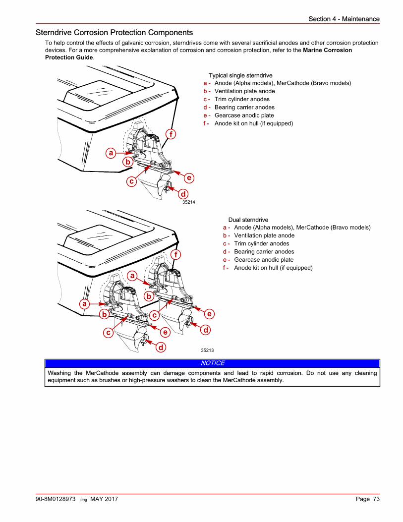
Sterndrive Corrosion Protection ComponentsTo help control the effects of galvanic corrosion, sterndrives come with several sacrificial anodes and other corrosion protectiondevices. For a more comprehensive explanation of corrosion and corrosion protection, refer to the Marine CorrosionProtection Guide.
Typical single sterndrivea - Anode (Alpha models), MerCathode (Bravo models)b - Ventilation plate anodec - Trim cylinder anodesd - Bearing carrier anodese - Gearcase anodic platef - Anode kit on hull (if equipped)
Dual sterndrivea - Anode (Alpha models), MerCathode (Bravo models)b - Ventilation plate anodec - Trim cylinder anodesd - Bearing carrier anodese - Gearcase anodic platef - Anode kit on hull (if equipped)
NOTICEWashing the MerCathode assembly can damage components and lead to rapid corrosion. Do not use any cleaningequipment such as brushes or high‑pressure washers to clean the MerCathode assembly.
a
cd
e
b
35214
f
f
a
a
c
c
d
d
e
e
b
b
35213
Section 4 - Maintenance
90-8M0128973 eng MAY 2017 Page 73
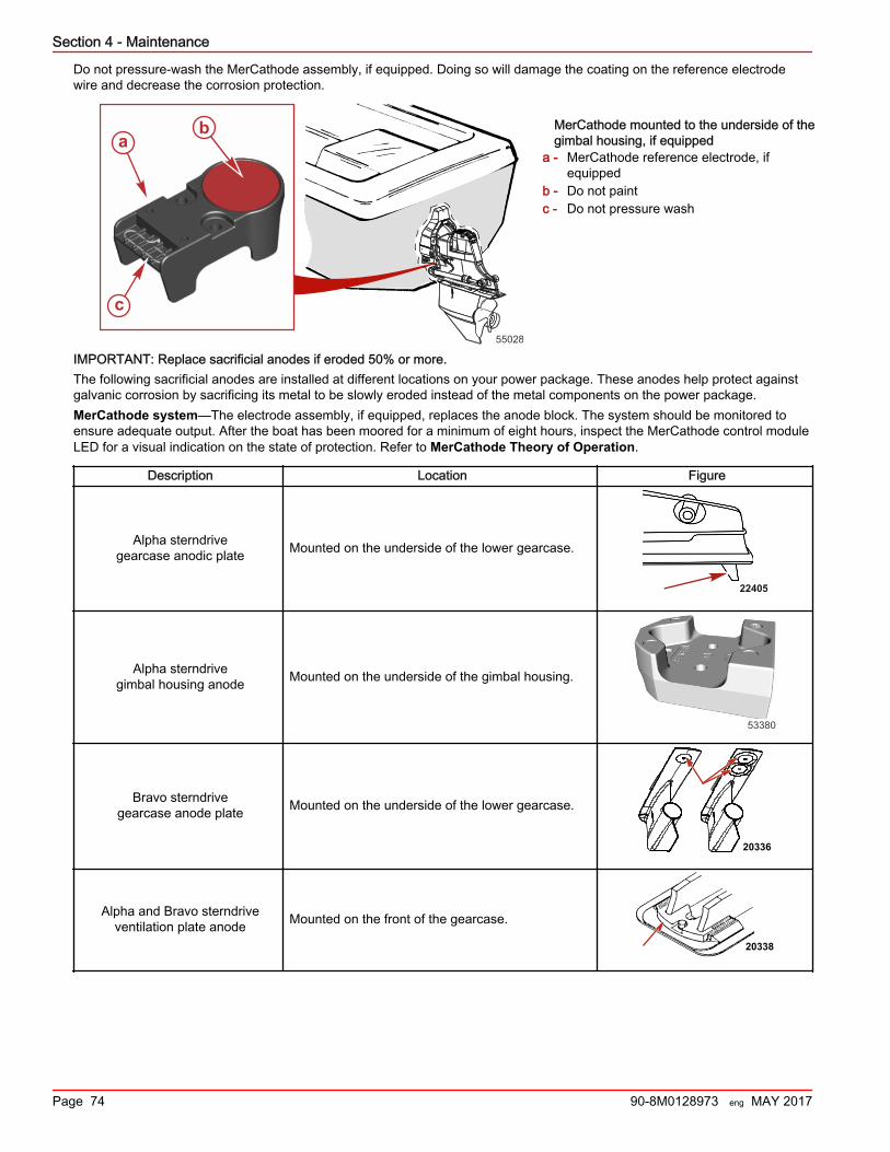
Do not pressure‑wash the MerCathode assembly, if equipped. Doing so will damage the coating on the reference electrodewire and decrease the corrosion protection.
MerCathode mounted to the underside of thegimbal housing, if equipped
a - MerCathode reference electrode, ifequipped
b - Do not paintc - Do not pressure wash
IMPORTANT: Replace sacrificial anodes if eroded 50% or more.The following sacrificial anodes are installed at different locations on your power package. These anodes help protect againstgalvanic corrosion by sacrificing its metal to be slowly eroded instead of the metal components on the power package.MerCathode system—The electrode assembly, if equipped, replaces the anode block. The system should be monitored toensure adequate output. After the boat has been moored for a minimum of eight hours, inspect the MerCathode control moduleLED for a visual indication on the state of protection. Refer to MerCathode Theory of Operation.
Description Location Figure
Alpha sterndrivegearcase anodic plate Mounted on the underside of the lower gearcase.
22405
Alpha sterndrivegimbal housing anode Mounted on the underside of the gimbal housing.
53380
Bravo sterndrivegearcase anode plate Mounted on the underside of the lower gearcase.
20336
Alpha and Bravo sterndriveventilation plate anode Mounted on the front of the gearcase.
20338
55028
a
c
b
Section 4 - Maintenance
Page 74 90-8M0128973 eng MAY 2017
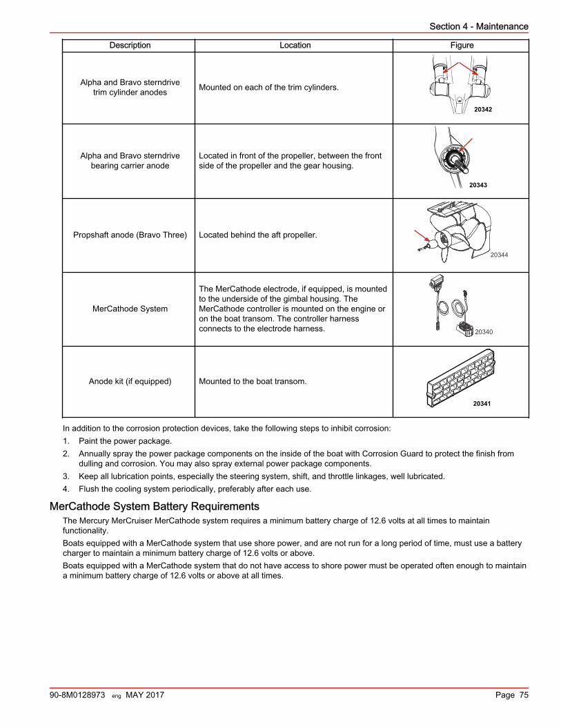
Description Location Figure
Alpha and Bravo sterndrivetrim cylinder anodes Mounted on each of the trim cylinders.
20342
Alpha and Bravo sterndrivebearing carrier anode
Located in front of the propeller, between the frontside of the propeller and the gear housing.
20343
Propshaft anode (Bravo Three) Located behind the aft propeller.
20344
MerCathode System
The MerCathode electrode, if equipped, is mountedto the underside of the gimbal housing. TheMerCathode controller is mounted on the engine oron the boat transom. The controller harnessconnects to the electrode harness. 20340
Anode kit (if equipped) Mounted to the boat transom.
20341
In addition to the corrosion protection devices, take the following steps to inhibit corrosion:1. Paint the power package.2. Annually spray the power package components on the inside of the boat with Corrosion Guard to protect the finish from
dulling and corrosion. You may also spray external power package components.3. Keep all lubrication points, especially the steering system, shift, and throttle linkages, well lubricated.4. Flush the cooling system periodically, preferably after each use.
MerCathode System Battery RequirementsThe Mercury MerCruiser MerCathode system requires a minimum battery charge of 12.6 volts at all times to maintainfunctionality.Boats equipped with a MerCathode system that use shore power, and are not run for a long period of time, must use a batterycharger to maintain a minimum battery charge of 12.6 volts or above.Boats equipped with a MerCathode system that do not have access to shore power must be operated often enough to maintaina minimum battery charge of 12.6 volts or above at all times.
Section 4 - Maintenance
90-8M0128973 eng MAY 2017 Page 75
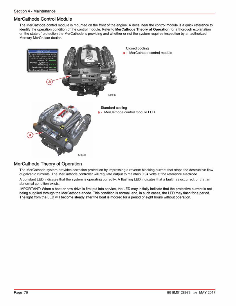
MerCathode Control ModuleThe MerCathode control module is mounted on the front of the engine. A decal near the control module is a quick reference toidentify the operation condition of the control module. Refer to MerCathode Theory of Operation for a thorough explanationon the state of protection the MerCathode is providing and whether or not the system requires inspection by an authorizedMercury MerCruiser dealer.
Closed coolinga - MerCathode control module
Standard coolinga - MerCathode control module LED
MerCathode Theory of OperationThe MerCathode system provides corrosion protection by impressing a reverse blocking current that stops the destructive flowof galvanic currents. The MerCathode controller will regulate output to maintain 0.94 volts at the reference electrode.A constant LED indicates that the system is operating correctly. A flashing LED indicates that a fault has occurred, or that anabnormal condition exists.IMPORTANT: When a boat or new drive is first put into service, the LED may initially indicate that the protective current is notbeing supplied through the MerCathode anode. This condition is normal, and, in such cases, the LED may flash for a period.The light from the LED will become steady after the boat is moored for a period of eight hours without operation.
a
54996
a
55620
Section 4 - Maintenance
Page 76 90-8M0128973 eng MAY 2017
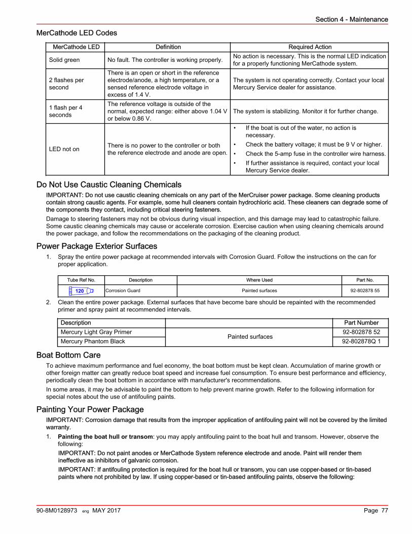
MerCathode LED Codes
MerCathode LED Definition Required Action
Solid green No fault. The controller is working properly. No action is necessary. This is the normal LED indicationfor a properly functioning MerCathode system.
2 flashes persecond
There is an open or short in the referenceelectrode/anode, a high temperature, or asensed reference electrode voltage inexcess of 1.4 V.
The system is not operating correctly. Contact your localMercury Service dealer for assistance.
1 flash per 4seconds
The reference voltage is outside of thenormal, expected range: either above 1.04 Vor below 0.86 V.
The system is stabilizing. Monitor it for further change.
LED not on There is no power to the controller or boththe reference electrode and anode are open.
• If the boat is out of the water, no action isnecessary.
• Check the battery voltage; it must be 9 V or higher.• Check the 5‑amp fuse in the controller wire harness.• If further assistance is required, contact your local
Mercury Service dealer.
Do Not Use Caustic Cleaning ChemicalsIMPORTANT: Do not use caustic cleaning chemicals on any part of the MerCruiser power package. Some cleaning productscontain strong caustic agents. For example, some hull cleaners contain hydrochloric acid. These cleaners can degrade some ofthe components they contact, including critical steering fasteners.Damage to steering fasteners may not be obvious during visual inspection, and this damage may lead to catastrophic failure.Some caustic cleaning chemicals may cause or accelerate corrosion. Exercise caution when using cleaning chemicals aroundthe power package, and follow the recommendations on the packaging of the cleaning product.
Power Package Exterior Surfaces1. Spray the entire power package at recommended intervals with Corrosion Guard. Follow the instructions on the can for
proper application.
Tube Ref No. Description Where Used Part No.
120 Corrosion Guard Painted surfaces 92-802878 55
2. Clean the entire power package. External surfaces that have become bare should be repainted with the recommendedprimer and spray paint at recommended intervals.
Description Part NumberMercury Light Gray Primer
Painted surfaces92‑802878 52
Mercury Phantom Black 92‑802878Q 1
Boat Bottom CareTo achieve maximum performance and fuel economy, the boat bottom must be kept clean. Accumulation of marine growth orother foreign matter can greatly reduce boat speed and increase fuel consumption. To ensure best performance and efficiency,periodically clean the boat bottom in accordance with manufacturer's recommendations.In some areas, it may be advisable to paint the bottom to help prevent marine growth. Refer to the following information forspecial notes about the use of antifouling paints.
Painting Your Power PackageIMPORTANT: Corrosion damage that results from the improper application of antifouling paint will not be covered by the limitedwarranty.1. Painting the boat hull or transom: you may apply antifouling paint to the boat hull and transom. However, observe the
following:IMPORTANT: Do not paint anodes or MerCathode System reference electrode and anode. Paint will render themineffective as inhibitors of galvanic corrosion.IMPORTANT: If antifouling protection is required for the boat hull or transom, you can use copper‑based or tin‑basedpaints where not prohibited by law. If using copper‑based or tin‑based antifouling paints, observe the following:
Section 4 - Maintenance
90-8M0128973 eng MAY 2017 Page 77
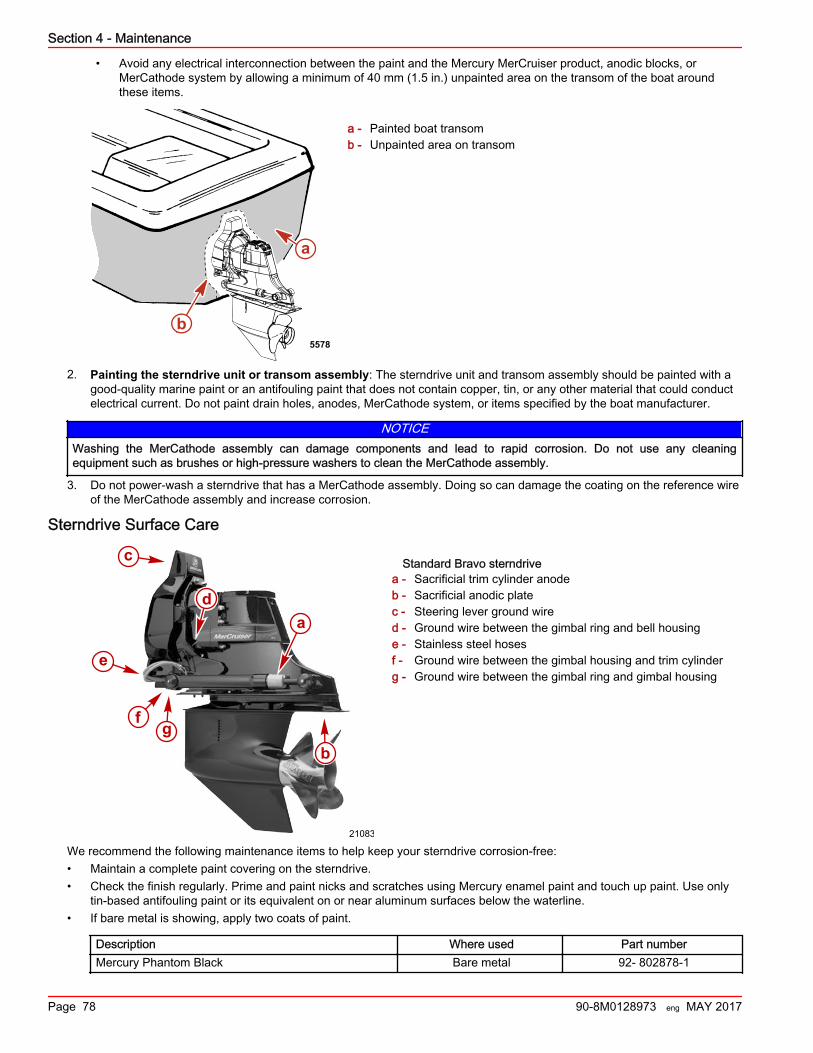
• Avoid any electrical interconnection between the paint and the Mercury MerCruiser product, anodic blocks, orMerCathode system by allowing a minimum of 40 mm (1.5 in.) unpainted area on the transom of the boat aroundthese items.
a - Painted boat transomb - Unpainted area on transom
2. Painting the sterndrive unit or transom assembly: The sterndrive unit and transom assembly should be painted with agood‑quality marine paint or an antifouling paint that does not contain copper, tin, or any other material that could conductelectrical current. Do not paint drain holes, anodes, MerCathode system, or items specified by the boat manufacturer.
NOTICEWashing the MerCathode assembly can damage components and lead to rapid corrosion. Do not use any cleaningequipment such as brushes or high‑pressure washers to clean the MerCathode assembly.
3. Do not power‑wash a sterndrive that has a MerCathode assembly. Doing so can damage the coating on the reference wireof the MerCathode assembly and increase corrosion.
Sterndrive Surface Care
Standard Bravo sterndrivea - Sacrificial trim cylinder anodeb - Sacrificial anodic platec - Steering lever ground wired - Ground wire between the gimbal ring and bell housinge - Stainless steel hosesf - Ground wire between the gimbal housing and trim cylinderg - Ground wire between the gimbal ring and gimbal housing
We recommend the following maintenance items to help keep your sterndrive corrosion‑free:• Maintain a complete paint covering on the sterndrive.• Check the finish regularly. Prime and paint nicks and scratches using Mercury enamel paint and touch up paint. Use only
tin‑based antifouling paint or its equivalent on or near aluminum surfaces below the waterline.• If bare metal is showing, apply two coats of paint.
Description Where used Part numberMercury Phantom Black Bare metal 92‑ 802878‑1
b
a
5578
21083
a
b
c
d
e
fg
Section 4 - Maintenance
Page 78 90-8M0128973 eng MAY 2017
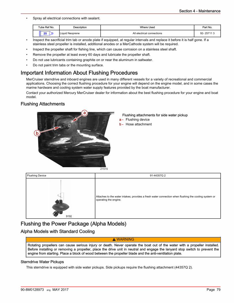
• Spray all electrical connections with sealant.
Tube Ref No. Description Where Used Part No.
25 Liquid Neoprene All electrical connections 92- 25711 3
• Inspect the sacrificial trim tab or anode plate if equipped, at regular intervals and replace it before it is half gone. If astainless steel propeller is installed, additional anodes or a MerCathode system will be required.
• Inspect the propeller shaft for fishing line, which can cause corrosion on a stainless steel shaft.• Remove the propeller at least every 60 days and lubricate the propeller shaft.• Do not use lubricants containing graphite on or near the aluminum in saltwater.• Do not paint trim tabs or the mounting surface.
Important Information About Flushing ProceduresMerCruiser sterndrive and inboard engines are used in many different vessels for a variety of recreational and commercialapplications. Choosing the correct flushing procedure for your engine will depend on the engine model, and in some cases themarine hardware and cooling system water supply features provided by the boat manufacturer.Contact your authorized Mercury MerCruiser dealer for information about the best flushing procedure for your engine and boatmodel.
Flushing Attachments
Flushing attachments for side water pickupa - Flushing deviceb - Hose attachment
Flushing Device 91‑44357Q 2
9192
Attaches to the water intakes; provides a fresh water connection when flushing the cooling system oroperating the engine.
Flushing the Power Package (Alpha Models)Alpha Models with Standard Cooling
! WARNINGRotating propellers can cause serious injury or death. Never operate the boat out of the water with a propeller installed.Before installing or removing a propeller, place the drive unit in neutral and engage the lanyard stop switch to prevent theengine from starting. Place a block of wood between the propeller blade and the anti‑ventilation plate.
Sterndrive Water PickupsThis sterndrive is equipped with side water pickups. Side pickups require the flushing attachment (44357Q 2).
21515
a
b
Section 4 - Maintenance
90-8M0128973 eng MAY 2017 Page 79
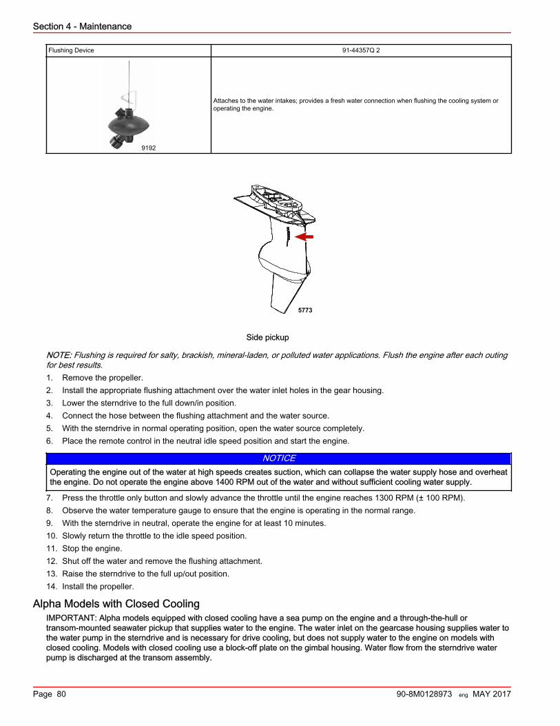
Flushing Device 91‑44357Q 2
9192
Attaches to the water intakes; provides a fresh water connection when flushing the cooling system oroperating the engine.
5773
Side pickup
NOTE: Flushing is required for salty, brackish, mineral‑laden, or polluted water applications. Flush the engine after each outingfor best results.1. Remove the propeller.2. Install the appropriate flushing attachment over the water inlet holes in the gear housing.3. Lower the sterndrive to the full down/in position.4. Connect the hose between the flushing attachment and the water source.5. With the sterndrive in normal operating position, open the water source completely.6. Place the remote control in the neutral idle speed position and start the engine.
NOTICEOperating the engine out of the water at high speeds creates suction, which can collapse the water supply hose and overheatthe engine. Do not operate the engine above 1400 RPM out of the water and without sufficient cooling water supply.
7. Press the throttle only button and slowly advance the throttle until the engine reaches 1300 RPM (± 100 RPM).8. Observe the water temperature gauge to ensure that the engine is operating in the normal range.9. With the sterndrive in neutral, operate the engine for at least 10 minutes.10. Slowly return the throttle to the idle speed position.11. Stop the engine.12. Shut off the water and remove the flushing attachment.13. Raise the sterndrive to the full up/out position.14. Install the propeller.
Alpha Models with Closed CoolingIMPORTANT: Alpha models equipped with closed cooling have a sea pump on the engine and a through‑the‑hull ortransom‑mounted seawater pickup that supplies water to the engine. The water inlet on the gearcase housing supplies water tothe water pump in the sterndrive and is necessary for drive cooling, but does not supply water to the engine on models withclosed cooling. Models with closed cooling use a block‑off plate on the gimbal housing. Water flow from the sterndrive waterpump is discharged at the transom assembly.
Section 4 - Maintenance
Page 80 90-8M0128973 eng MAY 2017
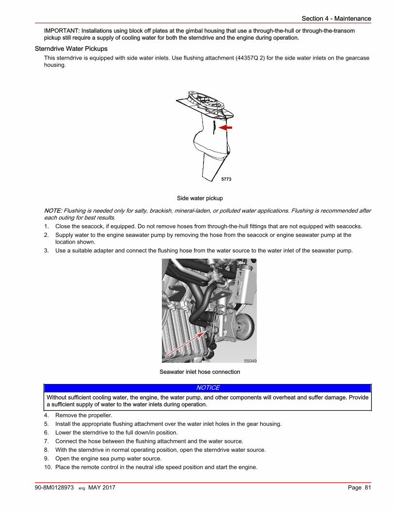
IMPORTANT: Installations using block off plates at the gimbal housing that use a through‑the‑hull or through‑the‑transompickup still require a supply of cooling water for both the sterndrive and the engine during operation.
Sterndrive Water PickupsThis sterndrive is equipped with side water inlets. Use flushing attachment (44357Q 2) for the side water inlets on the gearcasehousing.
5773
Side water pickup
NOTE: Flushing is needed only for salty, brackish, mineral‑laden, or polluted water applications. Flushing is recommended aftereach outing for best results.1. Close the seacock, if equipped. Do not remove hoses from through‑the‑hull fittings that are not equipped with seacocks.2. Supply water to the engine seawater pump by removing the hose from the seacock or engine seawater pump at the
location shown.3. Use a suitable adapter and connect the flushing hose from the water source to the water inlet of the seawater pump.
55049
Seawater inlet hose connection
NOTICEWithout sufficient cooling water, the engine, the water pump, and other components will overheat and suffer damage. Providea sufficient supply of water to the water inlets during operation.
4. Remove the propeller.5. Install the appropriate flushing attachment over the water inlet holes in the gear housing.6. Lower the sterndrive to the full down/in position.7. Connect the hose between the flushing attachment and the water source.8. With the sterndrive in normal operating position, open the sterndrive water source.9. Open the engine sea pump water source.10. Place the remote control in the neutral idle speed position and start the engine.
Section 4 - Maintenance
90-8M0128973 eng MAY 2017 Page 81
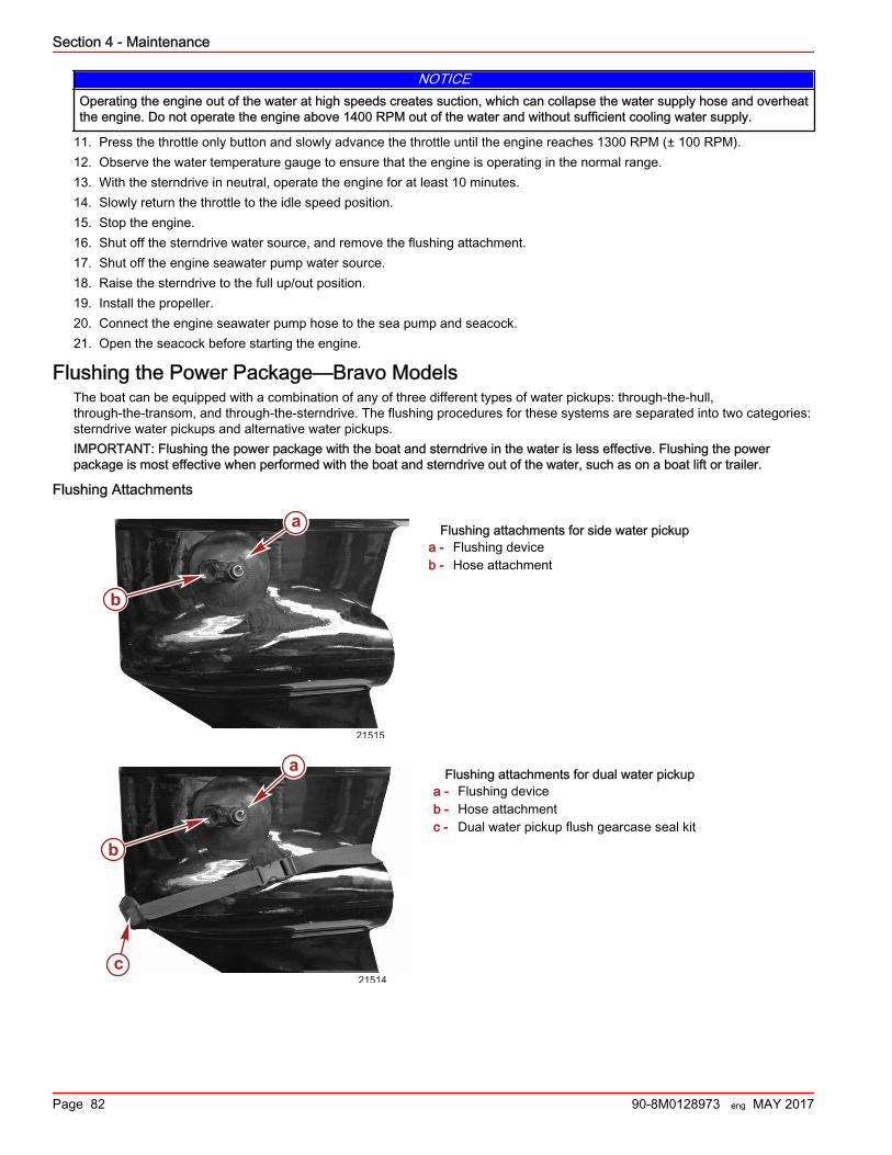
NOTICEOperating the engine out of the water at high speeds creates suction, which can collapse the water supply hose and overheatthe engine. Do not operate the engine above 1400 RPM out of the water and without sufficient cooling water supply.
11. Press the throttle only button and slowly advance the throttle until the engine reaches 1300 RPM (± 100 RPM).12. Observe the water temperature gauge to ensure that the engine is operating in the normal range.13. With the sterndrive in neutral, operate the engine for at least 10 minutes.14. Slowly return the throttle to the idle speed position.15. Stop the engine.16. Shut off the sterndrive water source, and remove the flushing attachment.17. Shut off the engine seawater pump water source.18. Raise the sterndrive to the full up/out position.19. Install the propeller.20. Connect the engine seawater pump hose to the sea pump and seacock.21. Open the seacock before starting the engine.
Flushing the Power Package—Bravo ModelsThe boat can be equipped with a combination of any of three different types of water pickups: through‑the‑hull,through‑the‑transom, and through‑the‑sterndrive. The flushing procedures for these systems are separated into two categories:sterndrive water pickups and alternative water pickups.IMPORTANT: Flushing the power package with the boat and sterndrive in the water is less effective. Flushing the powerpackage is most effective when performed with the boat and sterndrive out of the water, such as on a boat lift or trailer.
Flushing Attachments
Flushing attachments for side water pickupa - Flushing deviceb - Hose attachment
Flushing attachments for dual water pickupa - Flushing deviceb - Hose attachmentc - Dual water pickup flush gearcase seal kit
21515
a
b
a
b
c21514
Section 4 - Maintenance
Page 82 90-8M0128973 eng MAY 2017
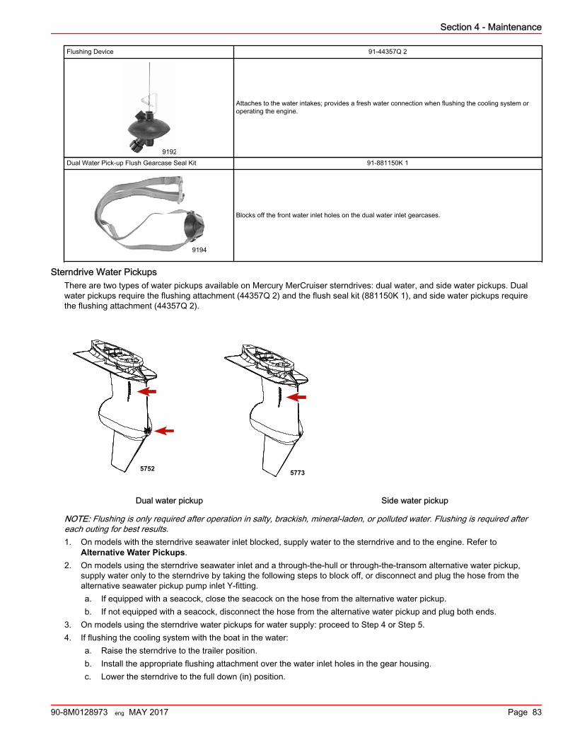
Flushing Device 91‑44357Q 2
9192
Attaches to the water intakes; provides a fresh water connection when flushing the cooling system oroperating the engine.
Dual Water Pick‑up Flush Gearcase Seal Kit 91‑881150K 1
9194
Blocks off the front water inlet holes on the dual water inlet gearcases.
Sterndrive Water PickupsThere are two types of water pickups available on Mercury MerCruiser sterndrives: dual water, and side water pickups. Dualwater pickups require the flushing attachment (44357Q 2) and the flush seal kit (881150K 1), and side water pickups requirethe flushing attachment (44357Q 2).
5752 5773
Dual water pickup Side water pickup
NOTE: Flushing is only required after operation in salty, brackish, mineral‑laden, or polluted water. Flushing is required aftereach outing for best results.1. On models with the sterndrive seawater inlet blocked, supply water to the sterndrive and to the engine. Refer to
Alternative Water Pickups.2. On models using the sterndrive seawater inlet and a through‑the‑hull or through‑the‑transom alternative water pickup,
supply water only to the sterndrive by taking the following steps to block off, or disconnect and plug the hose from thealternative seawater pickup pump inlet Y‑fitting.a. If equipped with a seacock, close the seacock on the hose from the alternative water pickup.b. If not equipped with a seacock, disconnect the hose from the alternative water pickup and plug both ends.
3. On models using the sterndrive water pickups for water supply: proceed to Step 4 or Step 5.4. If flushing the cooling system with the boat in the water:
a. Raise the sterndrive to the trailer position.b. Install the appropriate flushing attachment over the water inlet holes in the gear housing.c. Lower the sterndrive to the full down (in) position.
Section 4 - Maintenance
90-8M0128973 eng MAY 2017 Page 83
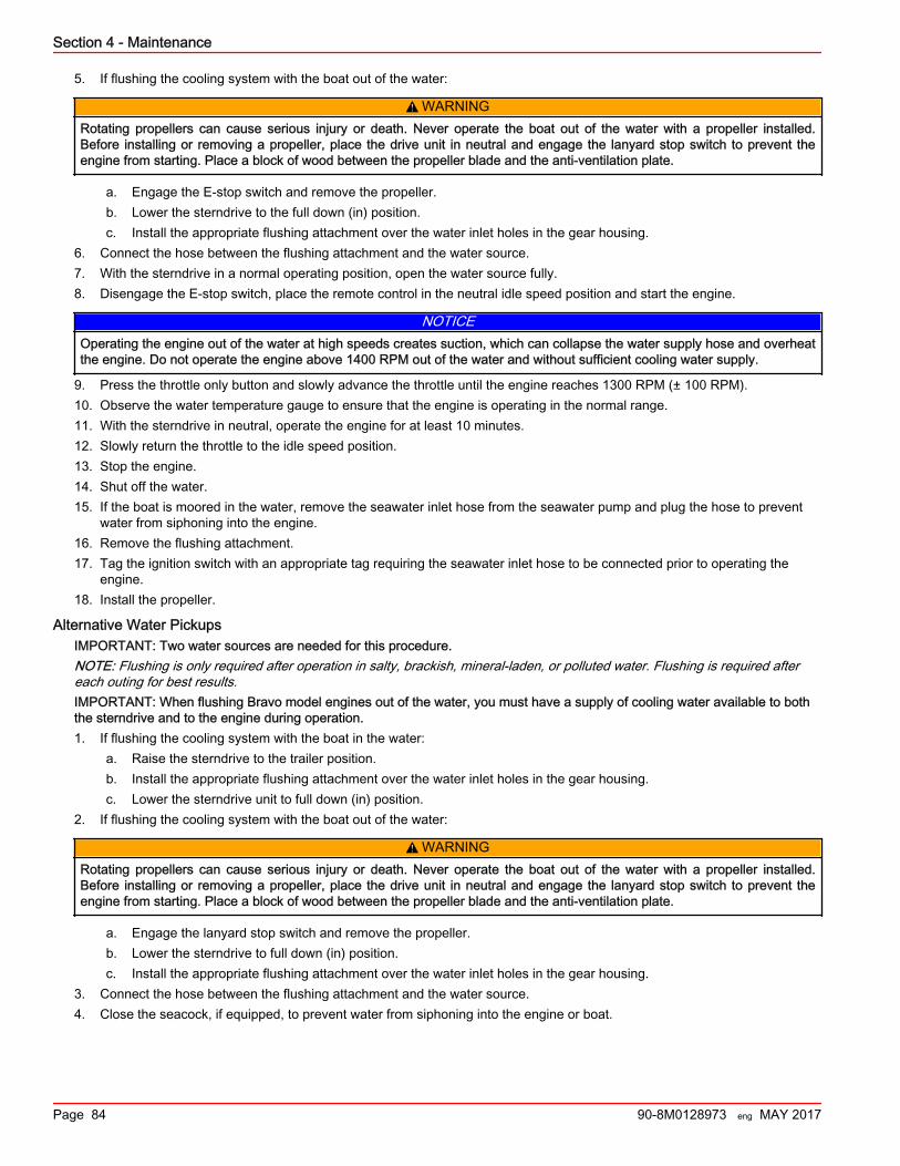
5. If flushing the cooling system with the boat out of the water:
! WARNINGRotating propellers can cause serious injury or death. Never operate the boat out of the water with a propeller installed.Before installing or removing a propeller, place the drive unit in neutral and engage the lanyard stop switch to prevent theengine from starting. Place a block of wood between the propeller blade and the anti‑ventilation plate.
a. Engage the E‑stop switch and remove the propeller.b. Lower the sterndrive to the full down (in) position.c. Install the appropriate flushing attachment over the water inlet holes in the gear housing.
6. Connect the hose between the flushing attachment and the water source.7. With the sterndrive in a normal operating position, open the water source fully.8. Disengage the E‑stop switch, place the remote control in the neutral idle speed position and start the engine.
NOTICEOperating the engine out of the water at high speeds creates suction, which can collapse the water supply hose and overheatthe engine. Do not operate the engine above 1400 RPM out of the water and without sufficient cooling water supply.
9. Press the throttle only button and slowly advance the throttle until the engine reaches 1300 RPM (± 100 RPM).10. Observe the water temperature gauge to ensure that the engine is operating in the normal range.11. With the sterndrive in neutral, operate the engine for at least 10 minutes.12. Slowly return the throttle to the idle speed position.13. Stop the engine.14. Shut off the water.15. If the boat is moored in the water, remove the seawater inlet hose from the seawater pump and plug the hose to prevent
water from siphoning into the engine.16. Remove the flushing attachment.17. Tag the ignition switch with an appropriate tag requiring the seawater inlet hose to be connected prior to operating the
engine.18. Install the propeller.
Alternative Water PickupsIMPORTANT: Two water sources are needed for this procedure.NOTE: Flushing is only required after operation in salty, brackish, mineral‑laden, or polluted water. Flushing is required aftereach outing for best results.IMPORTANT: When flushing Bravo model engines out of the water, you must have a supply of cooling water available to boththe sterndrive and to the engine during operation.1. If flushing the cooling system with the boat in the water:
a. Raise the sterndrive to the trailer position.b. Install the appropriate flushing attachment over the water inlet holes in the gear housing.c. Lower the sterndrive unit to full down (in) position.
2. If flushing the cooling system with the boat out of the water:
! WARNINGRotating propellers can cause serious injury or death. Never operate the boat out of the water with a propeller installed.Before installing or removing a propeller, place the drive unit in neutral and engage the lanyard stop switch to prevent theengine from starting. Place a block of wood between the propeller blade and the anti‑ventilation plate.
a. Engage the lanyard stop switch and remove the propeller.b. Lower the sterndrive to full down (in) position.c. Install the appropriate flushing attachment over the water inlet holes in the gear housing.
3. Connect the hose between the flushing attachment and the water source.4. Close the seacock, if equipped, to prevent water from siphoning into the engine or boat.
Section 4 - Maintenance
Page 84 90-8M0128973 eng MAY 2017
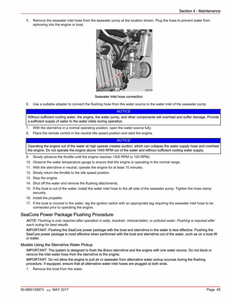
5. Remove the seawater inlet hose from the seawater pump at the location shown. Plug the hose to prevent water fromsiphoning into the engine or boat.
55049
Seawater inlet hose connection
6. Use a suitable adapter to connect the flushing hose from the water source to the water inlet of the seawater pump.
NOTICEWithout sufficient cooling water, the engine, the water pump, and other components will overheat and suffer damage. Providea sufficient supply of water to the water inlets during operation.
7. With the sterndrive in a normal operating position, open the water source fully.8. Place the remote control in the neutral idle speed position and start the engine.
NOTICEOperating the engine out of the water at high speeds creates suction, which can collapse the water supply hose and overheatthe engine. Do not operate the engine above 1400 RPM out of the water and without sufficient cooling water supply.
9. Slowly advance the throttle until the engine reaches 1300 RPM (± 100 RPM).10. Observe the water temperature gauge to ensure that the engine is operating in the normal range.11. With the sterndrive in neutral, operate the engine for at least 10 minutes.12. Slowly return the throttle to the idle speed position.13. Stop the engine.14. Shut off the water and remove the flushing attachments.15. If the boat is out of the water, install the water inlet hose to the aft side of the seawater pump. Tighten the hose clamp
securely.16. Install the propeller.17. If the boat is moored in the water, tag the ignition switch with an appropriate tag requiring the seawater inlet hose to be
connected prior to operating the engine.
SeaCore Power Package Flushing ProcedureNOTE: Flushing is only required after operation in salty, brackish, mineral‑laden, or polluted water. Flushing is required aftereach outing for best results.IMPORTANT: Flushing the SeaCore power package with the boat and sterndrive in the water is less effective. Flushing theSeaCore power package is most effective when performed with the boat and sterndrive out of the water, such as on a boat liftor trailer.
Models Using the Sterndrive Water PickupIMPORTANT: The system is designed to flush the Bravo sterndrive and the engine with one water source. Do not block orremove the inlet water hose from the sterndrive to the engine.IMPORTANT: Do not allow the engine to pull air or seawater from alternative water pickup sources during the flushingprocedure. If equipped, ensure that all alternative water inlet hoses are plugged at both ends.1. Remove the boat from the water.
Section 4 - Maintenance
90-8M0128973 eng MAY 2017 Page 85
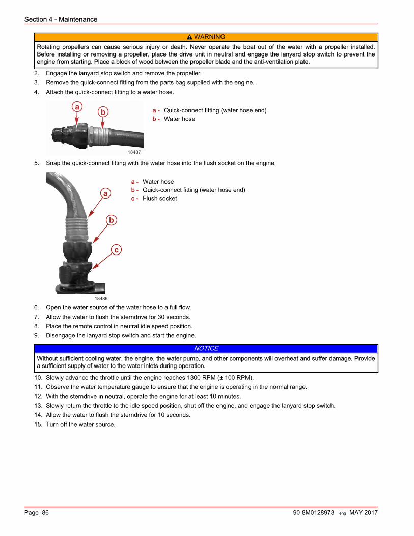
! WARNINGRotating propellers can cause serious injury or death. Never operate the boat out of the water with a propeller installed.Before installing or removing a propeller, place the drive unit in neutral and engage the lanyard stop switch to prevent theengine from starting. Place a block of wood between the propeller blade and the anti‑ventilation plate.
2. Engage the lanyard stop switch and remove the propeller.3. Remove the quick‑connect fitting from the parts bag supplied with the engine.4. Attach the quick‑connect fitting to a water hose.
a - Quick‑connect fitting (water hose end)b - Water hose
5. Snap the quick‑connect fitting with the water hose into the flush socket on the engine.
a - Water hoseb - Quick‑connect fitting (water hose end)c - Flush socket
6. Open the water source of the water hose to a full flow.7. Allow the water to flush the sterndrive for 30 seconds.8. Place the remote control in neutral idle speed position.9. Disengage the lanyard stop switch and start the engine.
NOTICEWithout sufficient cooling water, the engine, the water pump, and other components will overheat and suffer damage. Providea sufficient supply of water to the water inlets during operation.
10. Slowly advance the throttle until the engine reaches 1300 RPM (± 100 RPM).11. Observe the water temperature gauge to ensure that the engine is operating in the normal range.12. With the sterndrive in neutral, operate the engine for at least 10 minutes.13. Slowly return the throttle to the idle speed position, shut off the engine, and engage the lanyard stop switch.14. Allow the water to flush the sterndrive for 10 seconds.15. Turn off the water source.
18487
a b
a
b
c
18489
Section 4 - Maintenance
Page 86 90-8M0128973 eng MAY 2017
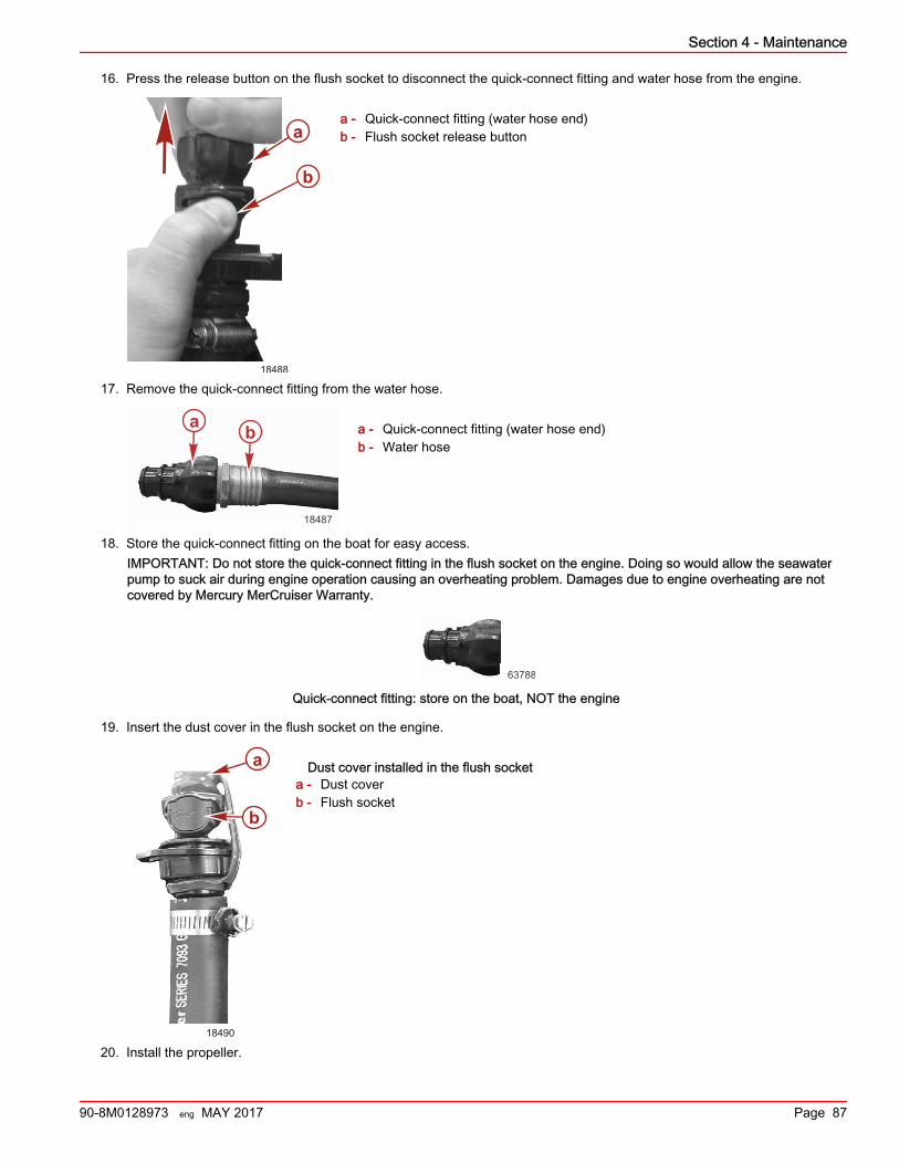
16. Press the release button on the flush socket to disconnect the quick‑connect fitting and water hose from the engine.
a - Quick‑connect fitting (water hose end)b - Flush socket release button
17. Remove the quick‑connect fitting from the water hose.
a - Quick‑connect fitting (water hose end)b - Water hose
18. Store the quick‑connect fitting on the boat for easy access.IMPORTANT: Do not store the quick‑connect fitting in the flush socket on the engine. Doing so would allow the seawaterpump to suck air during engine operation causing an overheating problem. Damages due to engine overheating are notcovered by Mercury MerCruiser Warranty.
63788
Quick-connect fitting: store on the boat, NOT the engine
19. Insert the dust cover in the flush socket on the engine.
Dust cover installed in the flush socketa - Dust coverb - Flush socket
20. Install the propeller.
b
a
18488
18487
a b
a
b
18490
Section 4 - Maintenance
90-8M0128973 eng MAY 2017 Page 87

Section 4 - Maintenance
Notes:
Page 88 90-8M0128973 eng MAY 2017
Section 5 - StorageTable of ContentsDraining the Seawater System............................................. 90
Draining the Raw Water.................................................90Air Actuated Single‑Point Drain System—Closed Cooling....................................................................................... 90Air Actuated Single‑Point Drain System (Bravo StandardCooling)......................................................................... 92Manual Single‑Point Drain System (Alpha StandardCooling)......................................................................... 94
Cold Weather or Extended Storage...................................... 95Reformulated (Oxygenated) Gasolines (U.S.A. Only)... 95Fuel Containing Alcohol................................................. 95Preparing Power Package for Storage—MPI Models....96
Special Fuel Mix .................................................... 96Engine and Fuel System Preparation .................... 97
Battery Storage..................................................................... 97Recommissioning the Power Package................................. 98
5
Section 5 - Storage
90-8M0128973 eng MAY 2017 Page 89
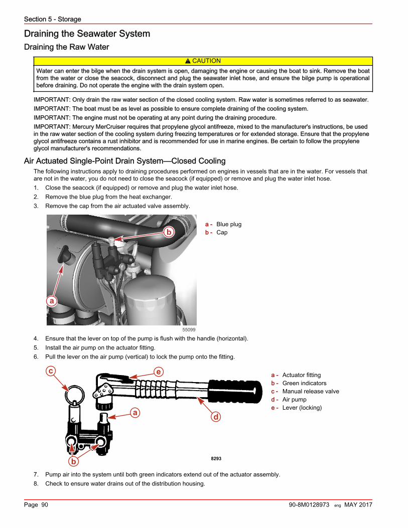
Draining the Seawater SystemDraining the Raw Water
! CAUTIONWater can enter the bilge when the drain system is open, damaging the engine or causing the boat to sink. Remove the boatfrom the water or close the seacock, disconnect and plug the seawater inlet hose, and ensure the bilge pump is operationalbefore draining. Do not operate the engine with the drain system open.
IMPORTANT: Only drain the raw water section of the closed cooling system. Raw water is sometimes referred to as seawater.IMPORTANT: The boat must be as level as possible to ensure complete draining of the cooling system.IMPORTANT: The engine must not be operating at any point during the draining procedure.IMPORTANT: Mercury MerCruiser requires that propylene glycol antifreeze, mixed to the manufacturer's instructions, be usedin the raw water section of the cooling system during freezing temperatures or for extended storage. Ensure that the propyleneglycol antifreeze contains a rust inhibitor and is recommended for use in marine engines. Be certain to follow the propyleneglycol manufacturer's recommendations.
Air Actuated Single‑Point Drain System—Closed CoolingThe following instructions apply to draining procedures performed on engines in vessels that are in the water. For vessels thatare not in the water, you do not need to close the seacock (if equipped) or remove and plug the water inlet hose.1. Close the seacock (if equipped) or remove and plug the water inlet hose.2. Remove the blue plug from the heat exchanger.3. Remove the cap from the air actuated valve assembly.
a - Blue plugb - Cap
4. Ensure that the lever on top of the pump is flush with the handle (horizontal).5. Install the air pump on the actuator fitting.6. Pull the lever on the air pump (vertical) to lock the pump onto the fitting.
a - Actuator fittingb - Green indicatorsc - Manual release valved - Air pumpe - Lever (locking)
7. Pump air into the system until both green indicators extend out of the actuator assembly.8. Check to ensure water drains out of the distribution housing.
55099
a
b
8293b
d
e
a
c
Section 5 - Storage
Page 90 90-8M0128973 eng MAY 2017
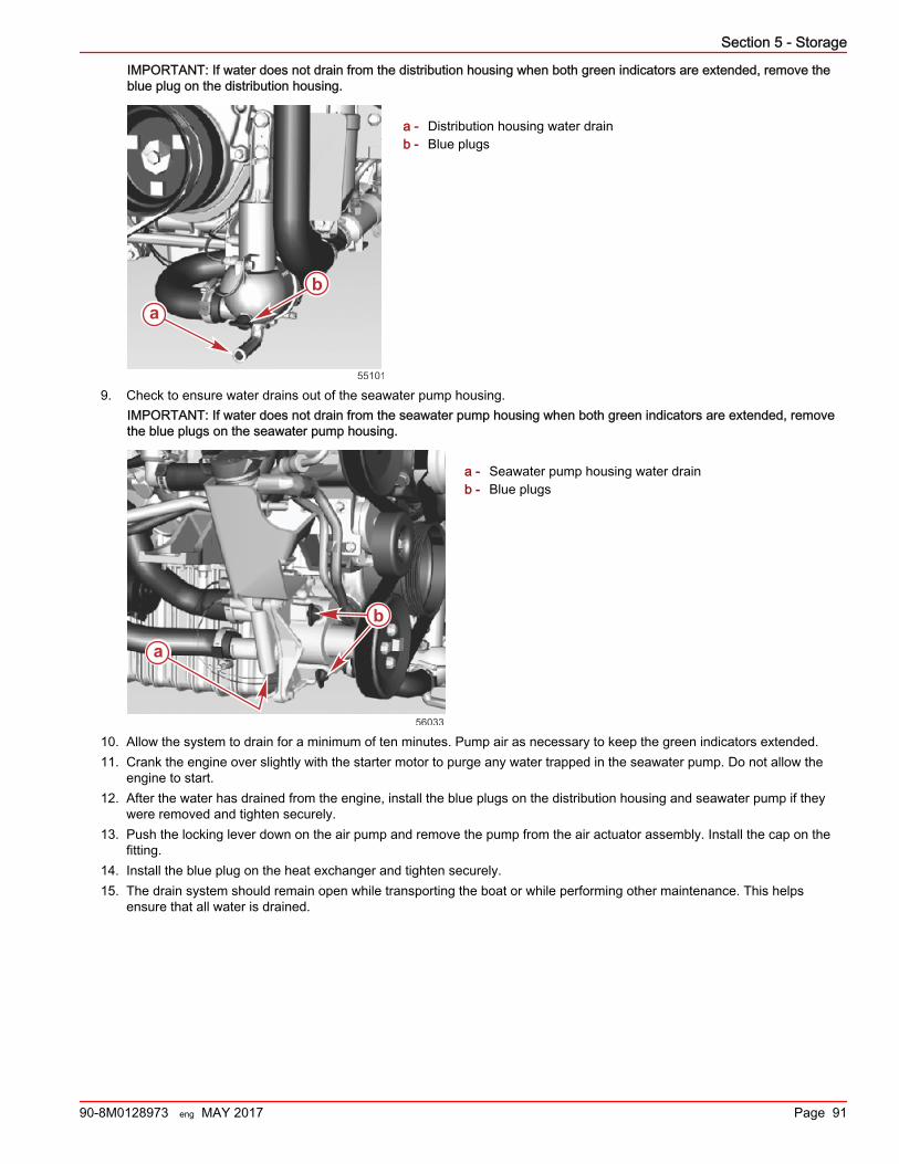
IMPORTANT: If water does not drain from the distribution housing when both green indicators are extended, remove theblue plug on the distribution housing.
a - Distribution housing water drainb - Blue plugs
9. Check to ensure water drains out of the seawater pump housing.IMPORTANT: If water does not drain from the seawater pump housing when both green indicators are extended, removethe blue plugs on the seawater pump housing.
a - Seawater pump housing water drainb - Blue plugs
10. Allow the system to drain for a minimum of ten minutes. Pump air as necessary to keep the green indicators extended.11. Crank the engine over slightly with the starter motor to purge any water trapped in the seawater pump. Do not allow the
engine to start.12. After the water has drained from the engine, install the blue plugs on the distribution housing and seawater pump if they
were removed and tighten securely.13. Push the locking lever down on the air pump and remove the pump from the air actuator assembly. Install the cap on the
fitting.14. Install the blue plug on the heat exchanger and tighten securely.15. The drain system should remain open while transporting the boat or while performing other maintenance. This helps
ensure that all water is drained.
ab
55101
a
b
56033
Section 5 - Storage
90-8M0128973 eng MAY 2017 Page 91
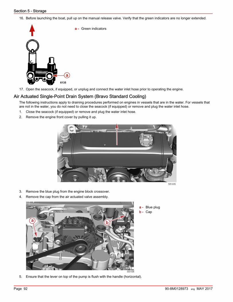
16. Before launching the boat, pull up on the manual release valve. Verify that the green indicators are no longer extended.
a - Green indicators
17. Open the seacock, if equipped, or unplug and connect the water inlet hose prior to operating the engine.
Air Actuated Single‑Point Drain System (Bravo Standard Cooling)The following instructions apply to draining procedures performed on engines in vessels that are in the water. For vessels thatare not in the water, you do not need to close the seacock (if equipped) or remove and plug the water inlet hose.1. Close the seacock (if equipped) or remove and plug the water inlet hose.2. Remove the engine front cover by pulling it up.
55105
3. Remove the blue plug from the engine block crossover.4. Remove the cap from the air actuated valve assembly.
a - Blue plugb - Cap
5. Ensure that the lever on top of the pump is flush with the handle (horizontal).
a6135
a b
55106
Section 5 - Storage
Page 92 90-8M0128973 eng MAY 2017
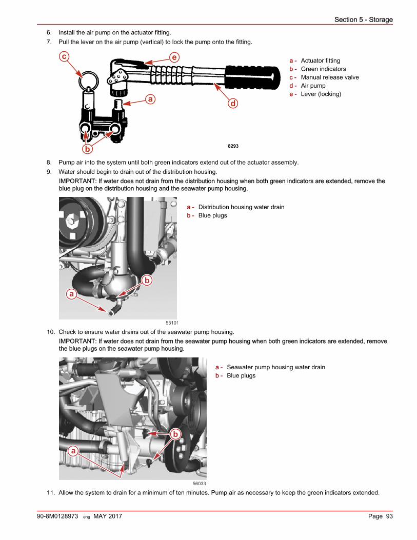
6. Install the air pump on the actuator fitting.7. Pull the lever on the air pump (vertical) to lock the pump onto the fitting.
a - Actuator fittingb - Green indicatorsc - Manual release valved - Air pumpe - Lever (locking)
8. Pump air into the system until both green indicators extend out of the actuator assembly.9. Water should begin to drain out of the distribution housing.
IMPORTANT: If water does not drain from the distribution housing when both green indicators are extended, remove theblue plug on the distribution housing and the seawater pump housing.
a - Distribution housing water drainb - Blue plugs
10. Check to ensure water drains out of the seawater pump housing.IMPORTANT: If water does not drain from the seawater pump housing when both green indicators are extended, removethe blue plugs on the seawater pump housing.
a - Seawater pump housing water drainb - Blue plugs
11. Allow the system to drain for a minimum of ten minutes. Pump air as necessary to keep the green indicators extended.
8293b
d
e
a
c
ab
55101
a
b
56033
Section 5 - Storage
90-8M0128973 eng MAY 2017 Page 93
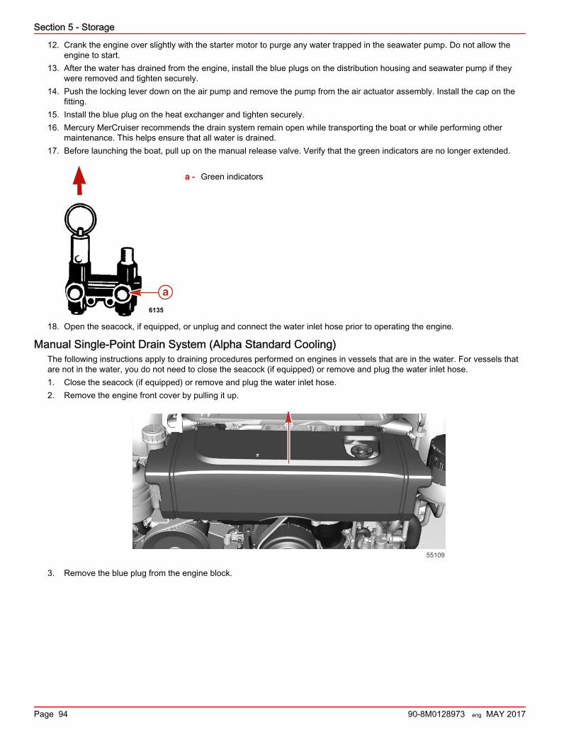
12. Crank the engine over slightly with the starter motor to purge any water trapped in the seawater pump. Do not allow theengine to start.
13. After the water has drained from the engine, install the blue plugs on the distribution housing and seawater pump if theywere removed and tighten securely.
14. Push the locking lever down on the air pump and remove the pump from the air actuator assembly. Install the cap on thefitting.
15. Install the blue plug on the heat exchanger and tighten securely.16. Mercury MerCruiser recommends the drain system remain open while transporting the boat or while performing other
maintenance. This helps ensure that all water is drained.17. Before launching the boat, pull up on the manual release valve. Verify that the green indicators are no longer extended.
a - Green indicators
18. Open the seacock, if equipped, or unplug and connect the water inlet hose prior to operating the engine.
Manual Single‑Point Drain System (Alpha Standard Cooling)The following instructions apply to draining procedures performed on engines in vessels that are in the water. For vessels thatare not in the water, you do not need to close the seacock (if equipped) or remove and plug the water inlet hose.1. Close the seacock (if equipped) or remove and plug the water inlet hose.2. Remove the engine front cover by pulling it up.
55109
3. Remove the blue plug from the engine block.
a6135
Section 5 - Storage
Page 94 90-8M0128973 eng MAY 2017
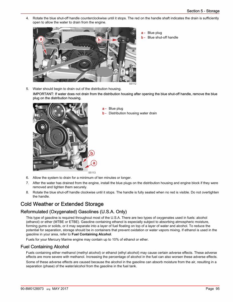
4. Rotate the blue shut‑off handle counterclockwise until it stops. The red on the handle shaft indicates the drain is sufficientlyopen to allow the water to drain from the engine.
a - Blue plugb - Blue shut‑off handle
5. Water should begin to drain out of the distribution housing.IMPORTANT: If water does not drain from the distribution housing after opening the blue shut‑off handle, remove the blueplug on the distribution housing.
a - Blue plugb - Distribution housing water drain
6. Allow the system to drain for a minimum of ten minutes or longer.7. After the water has drained from the engine, install the blue plugs on the distribution housing and engine block if they were
removed and tighten them securely.8. Rotate the blue shut‑off handle clockwise until it stops. The handle is fully seated when no red is visible. Do not overtighten
the handle.
Cold Weather or Extended StorageReformulated (Oxygenated) Gasolines (U.S.A. Only)
This type of gasoline is required throughout most of the U.S.A. There are two types of oxygenates used in fuels: alcohol(ethanol) or ether (MTBE or ETBE). Gasoline containing ethanol is especially subject to absorbing atmospheric moisture,forming gums or solids, or it may separate into a layer of fuel floating on top of a layer of water and alcohol. To reduce thepotential for separation, storage should be in containers that prevent oxidation or water vapors mixing. If ethanol is used in thegasoline in your area, refer to Fuel Containing Alcohol.Fuels for your Mercury Marine engine may contain up to 10% of ethanol or ether.
Fuel Containing AlcoholFuels containing either methanol (methyl alcohol) or ethanol (ethyl alcohol) may cause certain adverse effects. These adverseeffects are more severe with methanol. Increasing the percentage of alcohol in the fuel can also worsen these adverse effects.Some of these adverse effects are caused because the alcohol in the gasoline can absorb moisture from the air, resulting in aseparation (phase) of the water/alcohol from the gasoline in the fuel tank.
a b
55112
a
b
55113
Section 5 - Storage
90-8M0128973 eng MAY 2017 Page 95
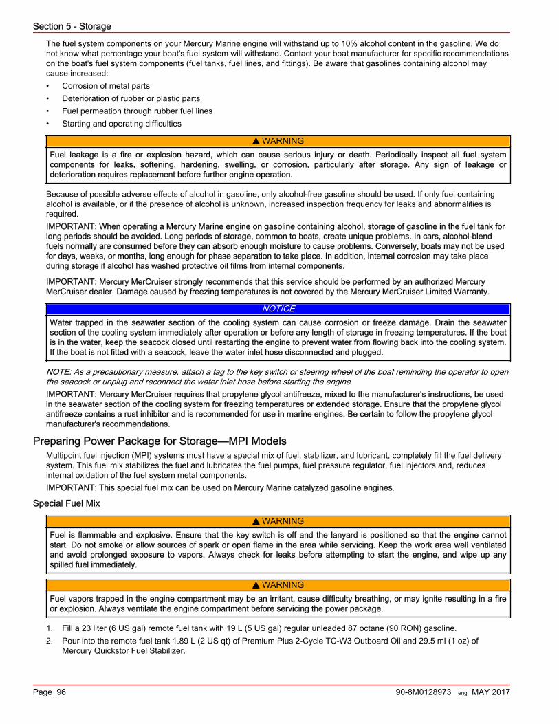
The fuel system components on your Mercury Marine engine will withstand up to 10% alcohol content in the gasoline. We donot know what percentage your boat's fuel system will withstand. Contact your boat manufacturer for specific recommendationson the boat's fuel system components (fuel tanks, fuel lines, and fittings). Be aware that gasolines containing alcohol maycause increased:• Corrosion of metal parts• Deterioration of rubber or plastic parts• Fuel permeation through rubber fuel lines• Starting and operating difficulties
! WARNINGFuel leakage is a fire or explosion hazard, which can cause serious injury or death. Periodically inspect all fuel systemcomponents for leaks, softening, hardening, swelling, or corrosion, particularly after storage. Any sign of leakage ordeterioration requires replacement before further engine operation.
Because of possible adverse effects of alcohol in gasoline, only alcohol‑free gasoline should be used. If only fuel containingalcohol is available, or if the presence of alcohol is unknown, increased inspection frequency for leaks and abnormalities isrequired.IMPORTANT: When operating a Mercury Marine engine on gasoline containing alcohol, storage of gasoline in the fuel tank forlong periods should be avoided. Long periods of storage, common to boats, create unique problems. In cars, alcohol‑blendfuels normally are consumed before they can absorb enough moisture to cause problems. Conversely, boats may not be usedfor days, weeks, or months, long enough for phase separation to take place. In addition, internal corrosion may take placeduring storage if alcohol has washed protective oil films from internal components.
IMPORTANT: Mercury MerCruiser strongly recommends that this service should be performed by an authorized MercuryMerCruiser dealer. Damage caused by freezing temperatures is not covered by the Mercury MerCruiser Limited Warranty.
NOTICEWater trapped in the seawater section of the cooling system can cause corrosion or freeze damage. Drain the seawatersection of the cooling system immediately after operation or before any length of storage in freezing temperatures. If the boatis in the water, keep the seacock closed until restarting the engine to prevent water from flowing back into the cooling system.If the boat is not fitted with a seacock, leave the water inlet hose disconnected and plugged.
NOTE: As a precautionary measure, attach a tag to the key switch or steering wheel of the boat reminding the operator to openthe seacock or unplug and reconnect the water inlet hose before starting the engine.IMPORTANT: Mercury MerCruiser requires that propylene glycol antifreeze, mixed to the manufacturer's instructions, be usedin the seawater section of the cooling system for freezing temperatures or extended storage. Ensure that the propylene glycolantifreeze contains a rust inhibitor and is recommended for use in marine engines. Be certain to follow the propylene glycolmanufacturer's recommendations.
Preparing Power Package for Storage—MPI ModelsMultipoint fuel injection (MPI) systems must have a special mix of fuel, stabilizer, and lubricant, completely fill the fuel deliverysystem. This fuel mix stabilizes the fuel and lubricates the fuel pumps, fuel pressure regulator, fuel injectors and, reducesinternal oxidation of the fuel system metal components.IMPORTANT: This special fuel mix can be used on Mercury Marine catalyzed gasoline engines.
Special Fuel Mix
! WARNINGFuel is flammable and explosive. Ensure that the key switch is off and the lanyard is positioned so that the engine cannotstart. Do not smoke or allow sources of spark or open flame in the area while servicing. Keep the work area well ventilatedand avoid prolonged exposure to vapors. Always check for leaks before attempting to start the engine, and wipe up anyspilled fuel immediately.
! WARNINGFuel vapors trapped in the engine compartment may be an irritant, cause difficulty breathing, or may ignite resulting in a fireor explosion. Always ventilate the engine compartment before servicing the power package.
1. Fill a 23 liter (6 US gal) remote fuel tank with 19 L (5 US gal) regular unleaded 87 octane (90 RON) gasoline.2. Pour into the remote fuel tank 1.89 L (2 US qt) of Premium Plus 2‑Cycle TC‑W3 Outboard Oil and 29.5 ml (1 oz) of
Mercury Quickstor Fuel Stabilizer.
Section 5 - Storage
Page 96 90-8M0128973 eng MAY 2017
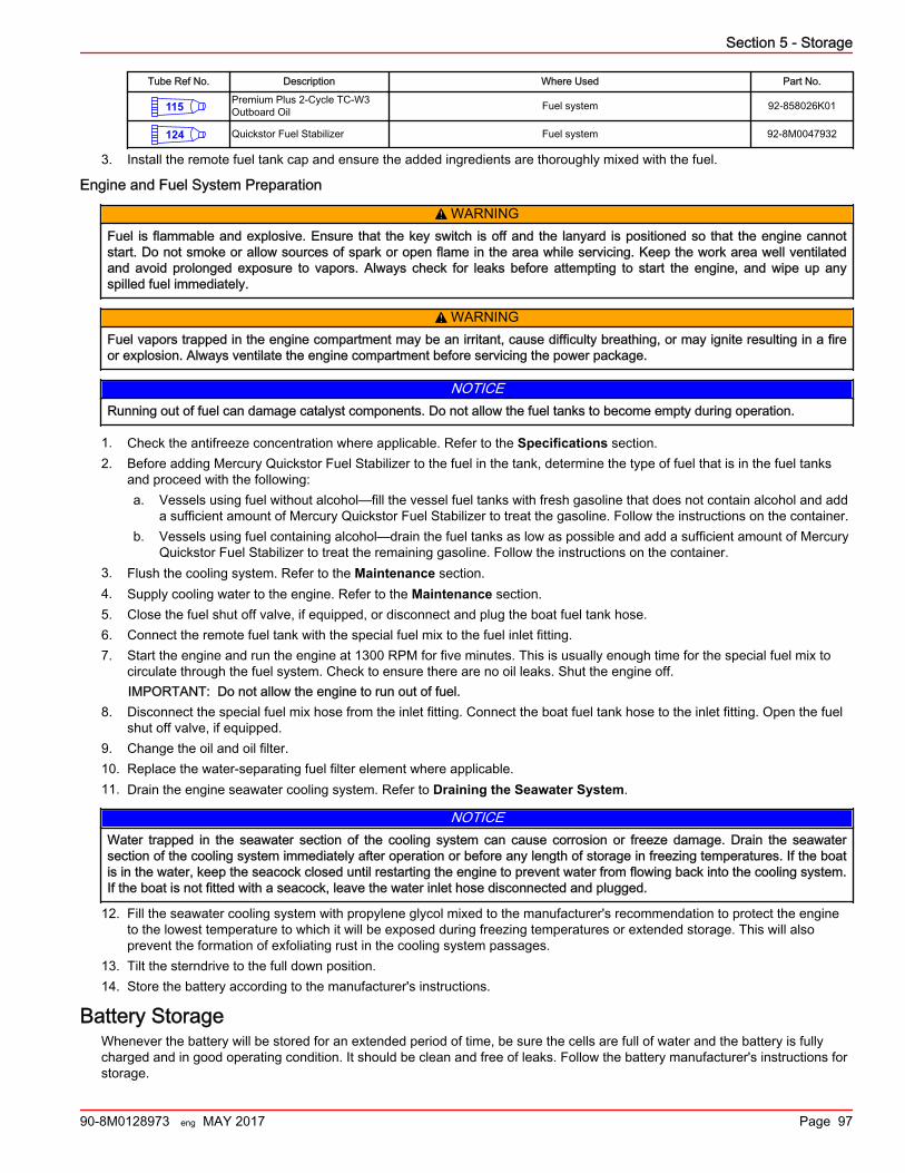
Tube Ref No. Description Where Used Part No.
115 Premium Plus 2-Cycle TC-W3Outboard Oil Fuel system 92-858026K01
124 Quickstor Fuel Stabilizer Fuel system 92-8M0047932
3. Install the remote fuel tank cap and ensure the added ingredients are thoroughly mixed with the fuel.
Engine and Fuel System Preparation
! WARNINGFuel is flammable and explosive. Ensure that the key switch is off and the lanyard is positioned so that the engine cannotstart. Do not smoke or allow sources of spark or open flame in the area while servicing. Keep the work area well ventilatedand avoid prolonged exposure to vapors. Always check for leaks before attempting to start the engine, and wipe up anyspilled fuel immediately.
! WARNINGFuel vapors trapped in the engine compartment may be an irritant, cause difficulty breathing, or may ignite resulting in a fireor explosion. Always ventilate the engine compartment before servicing the power package.
NOTICERunning out of fuel can damage catalyst components. Do not allow the fuel tanks to become empty during operation.
1. Check the antifreeze concentration where applicable. Refer to the Specifications section.2. Before adding Mercury Quickstor Fuel Stabilizer to the fuel in the tank, determine the type of fuel that is in the fuel tanks
and proceed with the following:a. Vessels using fuel without alcohol—fill the vessel fuel tanks with fresh gasoline that does not contain alcohol and add
a sufficient amount of Mercury Quickstor Fuel Stabilizer to treat the gasoline. Follow the instructions on the container.b. Vessels using fuel containing alcohol—drain the fuel tanks as low as possible and add a sufficient amount of Mercury
Quickstor Fuel Stabilizer to treat the remaining gasoline. Follow the instructions on the container.3. Flush the cooling system. Refer to the Maintenance section.4. Supply cooling water to the engine. Refer to the Maintenance section.5. Close the fuel shut off valve, if equipped, or disconnect and plug the boat fuel tank hose.6. Connect the remote fuel tank with the special fuel mix to the fuel inlet fitting.7. Start the engine and run the engine at 1300 RPM for five minutes. This is usually enough time for the special fuel mix to
circulate through the fuel system. Check to ensure there are no oil leaks. Shut the engine off.IMPORTANT: Do not allow the engine to run out of fuel.
8. Disconnect the special fuel mix hose from the inlet fitting. Connect the boat fuel tank hose to the inlet fitting. Open the fuelshut off valve, if equipped.
9. Change the oil and oil filter.10. Replace the water‑separating fuel filter element where applicable.11. Drain the engine seawater cooling system. Refer to Draining the Seawater System.
NOTICEWater trapped in the seawater section of the cooling system can cause corrosion or freeze damage. Drain the seawatersection of the cooling system immediately after operation or before any length of storage in freezing temperatures. If the boatis in the water, keep the seacock closed until restarting the engine to prevent water from flowing back into the cooling system.If the boat is not fitted with a seacock, leave the water inlet hose disconnected and plugged.
12. Fill the seawater cooling system with propylene glycol mixed to the manufacturer's recommendation to protect the engineto the lowest temperature to which it will be exposed during freezing temperatures or extended storage. This will alsoprevent the formation of exfoliating rust in the cooling system passages.
13. Tilt the sterndrive to the full down position.14. Store the battery according to the manufacturer's instructions.
Battery StorageWhenever the battery will be stored for an extended period of time, be sure the cells are full of water and the battery is fullycharged and in good operating condition. It should be clean and free of leaks. Follow the battery manufacturer's instructions forstorage.
Section 5 - Storage
90-8M0128973 eng MAY 2017 Page 97
Recommissioning the Power Package1. Ensure that all cooling system hoses are connected properly and hose clamps are tight.
! CAUTIONDisconnecting or connecting the battery cables in the incorrect order can cause injury from electrical shock or can damagethe electrical system. Always disconnect the negative (‑) battery cable first and connect it last.
2. Install a fully charged battery. Clean the battery cable clamps and terminals and reconnect the cables. Tighten each cableclamp securely when connecting.
3. Coat the terminal connections with a battery terminal anticorrosion agent.4. Perform all the checks in the Operation Chart.
NOTICEWithout sufficient cooling water, the engine, the water pump, and other components will overheat and suffer damage. Providea sufficient supply of water to the water inlets during operation.
5. Start the engine and closely observe instrumentation to ensure that all systems are functioning correctly.6. Carefully inspect the engine for fuel, oil, fluid, water, and exhaust leaks.7. Inspect the steering system, shift and throttle control for proper operation.
Section 5 - Storage
Page 98 90-8M0128973 eng MAY 2017
Section 6 - TroubleshootingTable of ContentsDiagnosing EFI Problems................................................... 100Diagnosing DTS Problems................................................. 100Additional Operation Instructions for Joystick PilotingSterndrive (JPS)................................................................. 100Engine Guardian System.................................................... 100Troubleshooting Charts...................................................... 100
Starter Motor Will Not Crank Engine, or Cranks Slowly..................................................................................... 100Engine Will Not Start or Is Hard to Start...................... 100Engine Runs Rough, Misses, or Backfires.................. 101Poor Performance........................................................101Excessive Engine Temperature................................... 101
Insufficient Engine Temperature.................................. 101Low Engine Oil Pressure............................................. 101Battery Will Not Recharge........................................... 102Remote Control Is Difficult to Move, Has Excessive Play,or Makes Unusual Sounds...........................................102Electronic Remote Controls......................................... 102Steering Wheel Jerks or Is Difficult to Turn................. 103Power Trim Does Not Operate (Motor Does Not Operate)..................................................................................... 103Power Trim Does Not Operate (Motor Operates butSterndrive Unit Does Not Move).................................. 103
6
Section 6 - Troubleshooting
90-8M0128973 eng MAY 2017 Page 99
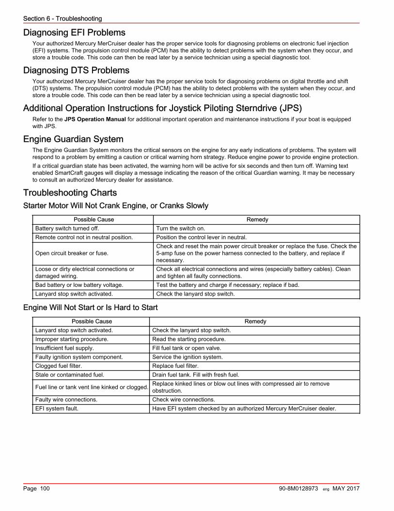
Diagnosing EFI ProblemsYour authorized Mercury MerCruiser dealer has the proper service tools for diagnosing problems on electronic fuel injection(EFI) systems. The propulsion control module (PCM) has the ability to detect problems with the system when they occur, andstore a trouble code. This code can then be read later by a service technician using a special diagnostic tool.
Diagnosing DTS ProblemsYour authorized Mercury MerCruiser dealer has the proper service tools for diagnosing problems on digital throttle and shift(DTS) systems. The propulsion control module (PCM) has the ability to detect problems with the system when they occur, andstore a trouble code. This code can then be read later by a service technician using a special diagnostic tool.
Additional Operation Instructions for Joystick Piloting Sterndrive (JPS)Refer to the JPS Operation Manual for additional important operation and maintenance instructions if your boat is equippedwith JPS.
Engine Guardian SystemThe Engine Guardian System monitors the critical sensors on the engine for any early indications of problems. The system willrespond to a problem by emitting a caution or critical warning horn strategy. Reduce engine power to provide engine protection.If a critical guardian state has been activated, the warning horn will be active for six seconds and then turn off. Warning textenabled SmartCraft gauges will display a message indicating the reason of the critical Guardian warning. It may be necessaryto consult an authorized Mercury dealer for assistance.
Troubleshooting ChartsStarter Motor Will Not Crank Engine, or Cranks Slowly
Possible Cause RemedyBattery switch turned off. Turn the switch on.Remote control not in neutral position. Position the control lever in neutral.
Open circuit breaker or fuse.Check and reset the main power circuit breaker or replace the fuse. Check the5‑amp fuse on the power harness connected to the battery, and replace ifnecessary.
Loose or dirty electrical connections ordamaged wiring.
Check all electrical connections and wires (especially battery cables). Cleanand tighten all faulty connections.
Bad battery or low battery voltage. Test the battery and charge if necessary; replace if bad.Lanyard stop switch activated. Check the lanyard stop switch.
Engine Will Not Start or Is Hard to Start
Possible Cause RemedyLanyard stop switch activated. Check the lanyard stop switch.Improper starting procedure. Read the starting procedure.Insufficient fuel supply. Fill fuel tank or open valve.Faulty ignition system component. Service the ignition system.Clogged fuel filter. Replace fuel filter.Stale or contaminated fuel. Drain fuel tank. Fill with fresh fuel.
Fuel line or tank vent line kinked or clogged. Replace kinked lines or blow out lines with compressed air to removeobstruction.
Faulty wire connections. Check wire connections.EFI system fault. Have EFI system checked by an authorized Mercury MerCruiser dealer.
Section 6 - Troubleshooting
Page 100 90-8M0128973 eng MAY 2017
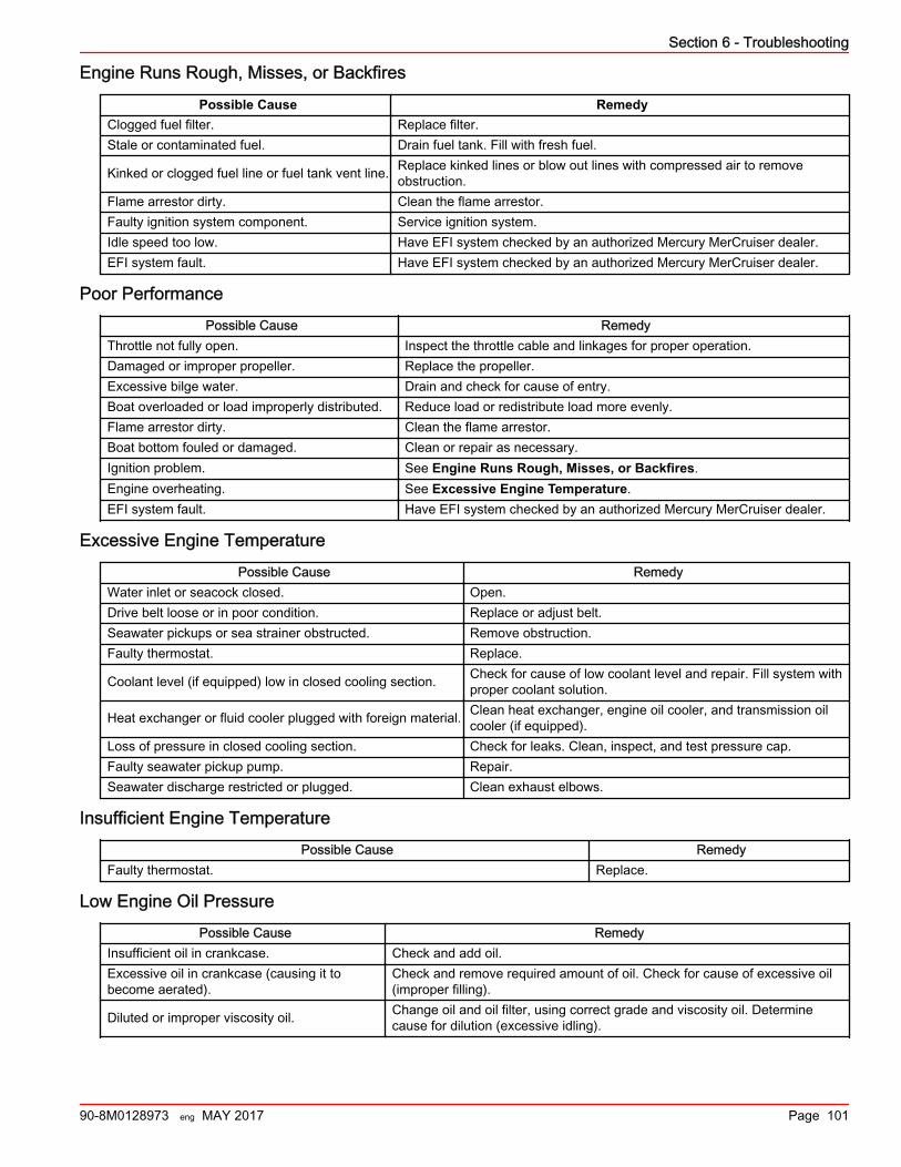
Engine Runs Rough, Misses, or Backfires
Possible Cause RemedyClogged fuel filter. Replace filter.Stale or contaminated fuel. Drain fuel tank. Fill with fresh fuel.
Kinked or clogged fuel line or fuel tank vent line. Replace kinked lines or blow out lines with compressed air to removeobstruction.
Flame arrestor dirty. Clean the flame arrestor.Faulty ignition system component. Service ignition system.Idle speed too low. Have EFI system checked by an authorized Mercury MerCruiser dealer.EFI system fault. Have EFI system checked by an authorized Mercury MerCruiser dealer.
Poor Performance
Possible Cause RemedyThrottle not fully open. Inspect the throttle cable and linkages for proper operation.Damaged or improper propeller. Replace the propeller.Excessive bilge water. Drain and check for cause of entry.Boat overloaded or load improperly distributed. Reduce load or redistribute load more evenly.Flame arrestor dirty. Clean the flame arrestor.Boat bottom fouled or damaged. Clean or repair as necessary.Ignition problem. See Engine Runs Rough, Misses, or Backfires.Engine overheating. See Excessive Engine Temperature.EFI system fault. Have EFI system checked by an authorized Mercury MerCruiser dealer.
Excessive Engine Temperature
Possible Cause RemedyWater inlet or seacock closed. Open.Drive belt loose or in poor condition. Replace or adjust belt.Seawater pickups or sea strainer obstructed. Remove obstruction.Faulty thermostat. Replace.
Coolant level (if equipped) low in closed cooling section. Check for cause of low coolant level and repair. Fill system withproper coolant solution.
Heat exchanger or fluid cooler plugged with foreign material. Clean heat exchanger, engine oil cooler, and transmission oilcooler (if equipped).
Loss of pressure in closed cooling section. Check for leaks. Clean, inspect, and test pressure cap.Faulty seawater pickup pump. Repair.Seawater discharge restricted or plugged. Clean exhaust elbows.
Insufficient Engine Temperature
Possible Cause RemedyFaulty thermostat. Replace.
Low Engine Oil Pressure
Possible Cause RemedyInsufficient oil in crankcase. Check and add oil.Excessive oil in crankcase (causing it tobecome aerated).
Check and remove required amount of oil. Check for cause of excessive oil(improper filling).
Diluted or improper viscosity oil. Change oil and oil filter, using correct grade and viscosity oil. Determinecause for dilution (excessive idling).
Section 6 - Troubleshooting
90-8M0128973 eng MAY 2017 Page 101
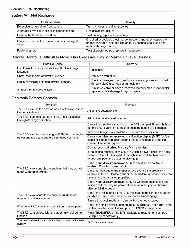
Battery Will Not Recharge
Possible Cause RemedyExcessive current draw from battery. Turn off nonessential accessories.Alternator drive belt loose or in poor condition. Replace and/or adjust.Unacceptable battery condition. Test battery, replace if necessary.
Loose or dirty electrical connections or damagedwiring.
Check all associated electrical connections and wires (especiallybattery cables). Clean and tighten faulty connections. Repair orreplace damaged wiring.
Faulty alternator. Test alternator output, replace if necessary.
Remote Control Is Difficult to Move, Has Excessive Play, or Makes Unusual Sounds
Possible Cause RemedyInsufficient lubrication on shift and throttle linkagefasteners. Lubricate.
Obstruction in shift or throttle linkages. Remove obstruction.
Loose or missing shift and throttle linkages. Check all linkages. If any are loose or missing, see authorizedMercury MerCruiser dealer immediately.
Shift or throttle cable kinked. Straighten cable or have authorized Mercury MerCruiser dealerreplace cable if damaged beyond repair.
Electronic Remote Controls
Symptom RemedyThe ERC lever is too hard or too easy to move out ofthe neutral detent. Adjust the detent tension.
The ERC lever has too much or too little resistancethrough its range of motion. Adjust the handle tension screw.
The ERC lever increases engine RPM, but the enginesdo not engage gears and the boat does not move.
Check the throttle‑only button on the DTS trackpad. If the light is on,put the ERC levers in neutral and push the button to disengage.Turn off all engine key switches. Then turn them back on.Check your Mercury‑approved multifunction display (MFD) for faultcodes or popup warnings. Expand the fault code text to see if acourse of action is required.Contact your authorized Mercury Marine dealer.
The ERC lever controls the engines, but they do notreach wide‑open throttle.
If the engine reaches only 50% of available power, check the dockbutton on the DTS trackpad. If the light is on, put the handles inneutral and push the button to disengage.Check your Mercury‑approved MFD to see if cruise control isenabled. Disable cruise control.Check for damage to the propeller, and change the propeller ifdamage is found. Contact your authorized Mercury Marine dealer forservice on the damaged propeller.Check your Mercury‑approved MFD for Guardian fault codes thatindicate reduced engine power. If found, contact your authorizedMercury Marine dealer.
The ERC lever controls the engine, but does notrespond in a linear manner.
Check the troll button on the DTS trackpad. If the light is on, put thehandles in neutral and push the troll button to disengage.Ensure that dock mode or cruise control are not engaged.
When one ERC lever is moved, all engines respond. Check the single‑lever button on the DTS trackpad. If the light is on,put the handles in neutral and push 1 LEVER to disengage.
The ERC control, joystick, and steering wheel do notfunction.
Press TRANSFER on the DTS trackpad to restore helm control.(Multiple helm boats only.)
The boat moves forward, but will not move backwardsquickly. Trim the drives down.
Section 6 - Troubleshooting
Page 102 90-8M0128973 eng MAY 2017
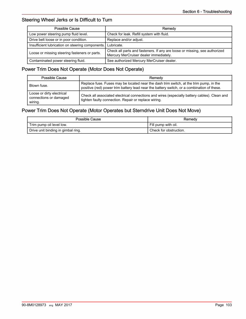
Steering Wheel Jerks or Is Difficult to Turn
Possible Cause RemedyLow power steering pump fluid level. Check for leak. Refill system with fluid.Drive belt loose or in poor condition. Replace and/or adjust.Insufficient lubrication on steering components. Lubricate.
Loose or missing steering fasteners or parts. Check all parts and fasteners. If any are loose or missing, see authorizedMercury MerCruiser dealer immediately.
Contaminated power steering fluid. See authorized Mercury MerCruiser dealer.
Power Trim Does Not Operate (Motor Does Not Operate)
Possible Cause Remedy
Blown fuse. Replace fuse. Fuses may be located near the dash trim switch, at the trim pump, in thepositive (red) power trim battery lead near the battery switch, or a combination of these.
Loose or dirty electricalconnections or damagedwiring.
Check all associated electrical connections and wires (especially battery cables). Clean andtighten faulty connection. Repair or replace wiring.
Power Trim Does Not Operate (Motor Operates but Sterndrive Unit Does Not Move)
Possible Cause RemedyTrim pump oil level low. Fill pump with oil.Drive unit binding in gimbal ring. Check for obstruction.
Section 6 - Troubleshooting
90-8M0128973 eng MAY 2017 Page 103

Section 6 - Troubleshooting
Notes:
Page 104 90-8M0128973 eng MAY 2017
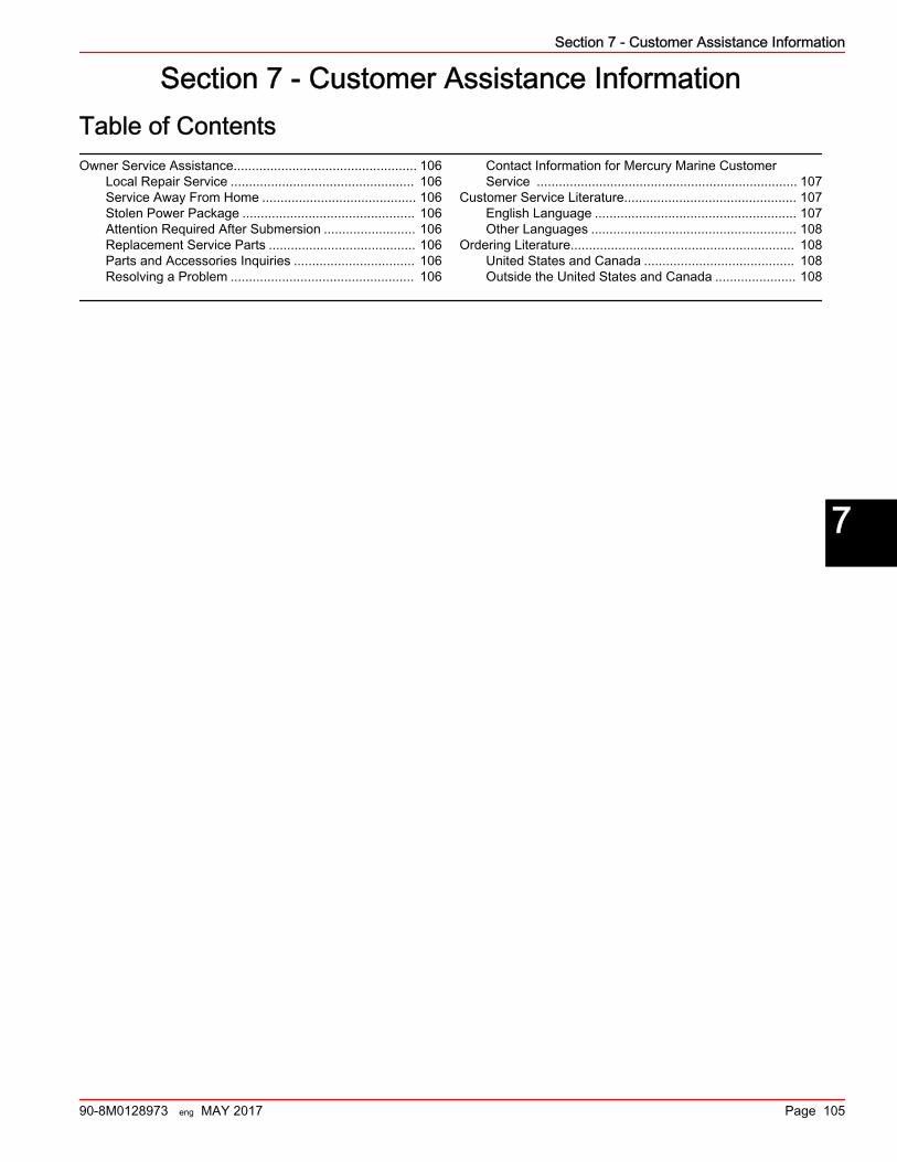
Section 7 - Customer Assistance InformationTable of ContentsOwner Service Assistance.................................................. 106
Local Repair Service .................................................. 106Service Away From Home .......................................... 106Stolen Power Package ............................................... 106Attention Required After Submersion ......................... 106Replacement Service Parts ........................................ 106Parts and Accessories Inquiries ................................. 106Resolving a Problem .................................................. 106
Contact Information for Mercury Marine CustomerService ....................................................................... 107
Customer Service Literature............................................... 107English Language ....................................................... 107Other Languages ........................................................ 108
Ordering Literature............................................................. 108United States and Canada ......................................... 108Outside the United States and Canada ...................... 108
7
Section 7 - Customer Assistance Information
90-8M0128973 eng MAY 2017 Page 105
Owner Service AssistanceLocal Repair Service
If you need service for your Mercury MerCruiser‑powered boat, take it to your authorized dealer. Only authorized dealersspecialize in Mercury MerCruiser products and have factory‑trained mechanics, special tools and equipment, and genuineQuicksilver parts and accessories to properly service your engine.NOTE: Quicksilver parts and accessories are engineered and built by Mercury Marine specifically for Mercury MerCruisersterndrives and inboards.
Service Away From HomeIf you are away from your local dealer and the need arises for service, contact the nearest authorized dealer. If, for any reason,you cannot obtain service, contact the nearest regional service center. Outside the United States and Canada, contact thenearest Marine Power International service center.
Stolen Power PackageIf your power package is stolen, immediately inform the local authorities and Mercury Marine of the model and serial numbersand to whom the recovery is to be reported. This information is maintained in a database at Mercury Marine to aid authoritiesand dealers in recovery of stolen power packages.
Attention Required After Submersion1. Before recovery, contact an authorized Mercury MerCruiser dealer.2. After recovery, immediate service by an authorized Mercury MerCruiser dealer is required to reduce the possibility of
serious engine damage.
Replacement Service Parts! WARNING
Avoid fire or explosion hazard. Electrical, ignition, and fuel system components on Mercury Marine products comply withfederal and international standards to minimize risk of fire or explosion. Do not use replacement electrical or fuel systemcomponents that do not comply with these standards. When servicing the electrical and fuel systems, properly install andtighten all components.
Marine engines are expected to operate at or near full throttle for most of their life. They are also expected to operate in bothfresh and saltwater environments. These conditions require numerous special parts. Exercise care when replacing marineengine parts because specifications are different from those of the standard automotive engine. For example, one of the mostimportant special replacement parts is the cylinder head gasket. Marine engines cannot use steel‑type automotive headgaskets because saltwater is highly corrosive. A marine engine head gasket uses special materials to resist corrosion.Because marine engines must be capable of running at or near maximum RPM much of the time, they also have special valvesprings, valve lifters, pistons, bearings, camshafts, and other heavy‑duty moving parts.Mercury MerCruiser marine engines have other special modifications to provide long life and dependable performance.
Parts and Accessories InquiriesDirect any questions concerning genuine Mercury Precision Parts or Quicksilver Marine Parts and Accessories to a localauthorized dealer. Dealers have the proper systems to order parts and accessories, if they are not in stock. Engine model andserial number are required to order correct parts.
Resolving a ProblemSatisfaction with your Mercury MerCruiser product is important to your dealer and to us. If you ever have a problem, question,or concern about your power package, contact your dealer or any authorized Mercury MerCruiser dealership. If you needadditional assistance:1. Talk with the dealership's sales manager or service manager. Contact the owner of the dealership if the sales manager and
service manager have been unable to resolve the problem.2. If your question, concern, or problem cannot be resolved by your dealership, please contact a Mercury Marine Service
Office for assistance. Mercury Marine will work with you and your dealership to resolve all problems.The following information will be needed by Customer Service:• Your name and address• Daytime telephone number• Model and serial numbers for your power package• The name and address of your dealership
Section 7 - Customer Assistance Information
Page 106 90-8M0128973 eng MAY 2017
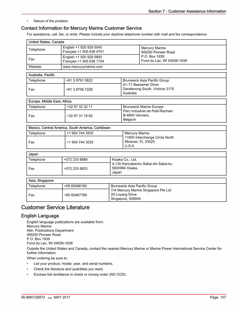
• Nature of the problem
Contact Information for Mercury Marine Customer ServiceFor assistance, call, fax, or write. Please include your daytime telephone number with mail and fax correspondence.
United States, Canada
Telephone English +1 920 929 5040Français +1 905 636 4751
Mercury MarineW6250 Pioneer RoadP.O. Box 1939Fond du Lac, WI 54936-1939Fax English +1 920 929 5893
Français +1 905 636 1704Website www.mercurymarine.com
Australia, PacificTelephone +61 3 9791 5822 Brunswick Asia Pacific Group
41–71 Bessemer DriveDandenong South, Victoria 3175Australia
Fax +61 3 9706 7228
Europe, Middle East, AfricaTelephone +32 87 32 32 11 Brunswick Marine Europe
Parc Industriel de Petit-RechainB-4800 Verviers,Belgium
Fax +32 87 31 19 65
Mexico, Central America, South America, CaribbeanTelephone +1 954 744 3500 Mercury Marine
11650 Interchange Circle NorthMiramar, FL 33025U.S.A.
Fax +1 954 744 3535
JapanTelephone +072 233 8888 Kisaka Co., Ltd.
4-130 Kannabecho Sakai-shi Sakai-ku5900984 Osaka,Japan
Fax +072 233 8833
Asia, SingaporeTelephone +65 65466160 Brunswick Asia Pacific Group
T/A Mercury Marine Singapore Pte Ltd29 Loyang DriveSingapore, 508944
Fax +65 65467789
Customer Service LiteratureEnglish Language
English language publications are available from:Mercury MarineAttn: Publications DepartmentW6250 Pioneer RoadP.O. Box 1939Fond du Lac, WI 54936-1939Outside the United States and Canada, contact the nearest Mercury Marine or Marine Power International Service Center forfurther information.When ordering be sure to:• List your product, model, year, and serial numbers.• Check the literature and quantities you want.• Enclose full remittance in check or money order (NO COD).
Section 7 - Customer Assistance Information
90-8M0128973 eng MAY 2017 Page 107
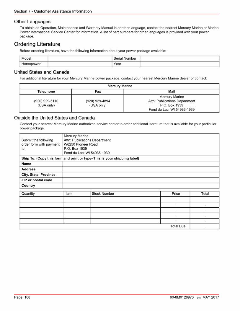
Other LanguagesTo obtain an Operation, Maintenance and Warranty Manual in another language, contact the nearest Mercury Marine or MarinePower International Service Center for information. A list of part numbers for other languages is provided with your powerpackage.
Ordering LiteratureBefore ordering literature, have the following information about your power package available:
Model Serial NumberHorsepower Year
United States and CanadaFor additional literature for your Mercury Marine power package, contact your nearest Mercury Marine dealer or contact:
Mercury MarineTelephone Fax Mail
(920) 929‑5110(USA only)
(920) 929‑4894(USA only)
Mercury MarineAttn: Publications Department
P.O. Box 1939Fond du Lac, WI 54936-1939
Outside the United States and CanadaContact your nearest Mercury Marine authorized service center to order additional literature that is available for your particularpower package.
Submit the followingorder form with paymentto:
Mercury MarineAttn: Publications DepartmentW6250 Pioneer RoadP.O. Box 1939Fond du Lac, WI 54936-1939
Ship To: (Copy this form and print or type–This is your shipping label)NameAddressCity, State, ProvinceZIP or postal codeCountry
Quantity Item Stock Number Price Total. .. .. .. .. .
Total Due .
Section 7 - Customer Assistance Information
Page 108 90-8M0128973 eng MAY 2017
Section 8 - ChecklistsTable of ContentsPredelivery Inspection (PDI)............................................... 110 Customer Delivery Inspection (CDI)................................... 111
8
Section 8 - Checklists
90-8M0128973 eng MAY 2017 Page 109
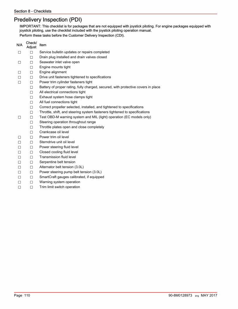
Predelivery Inspection (PDI)IMPORTANT: This checklist is for packages that are not equipped with joystick piloting. For engine packages equipped withjoystick piloting, use the checklist included with the joystick piloting operation manual.Perform these tasks before the Customer Delivery Inspection (CDI).
N/A Check/Adjust Item
⃞ ⃞ Service bulletin updates or repairs completed⃞ Drain plug installed and drain valves closed
⃞ ⃞ Seawater inlet valve open⃞ Engine mounts tight
⃞ ⃞ Engine alignment⃞ ⃞ Drive unit fasteners tightened to specifications⃞ ⃞ Power trim cylinder fasteners tight
⃞ Battery of proper rating, fully charged, secured, with protective covers in place⃞ All electrical connections tight⃞ Exhaust system hose clamps tight⃞ All fuel connections tight⃞ Correct propeller selected, installed, and tightened to specifications⃞ Throttle, shift, and steering system fasteners tightened to specifications
⃞ ⃞ Test OBD‑M warning system and MIL (light) operation (EC models only)⃞ Steering operation throughout range⃞ Throttle plates open and close completely⃞ Crankcase oil level
⃞ ⃞ Power trim oil level⃞ ⃞ Sterndrive unit oil level⃞ ⃞ Power steering fluid level⃞ ⃞ Closed cooling fluid level⃞ ⃞ Transmission fluid level⃞ ⃞ Serpentine belt tension⃞ ⃞ Alternator belt tension (3.0L)⃞ ⃞ Power steering pump belt tension (3.0L)⃞ ⃞ SmartCraft gauges calibrated, if equipped⃞ ⃞ Warning system operation⃞ ⃞ Trim limit switch operation
Section 8 - Checklists
Page 110 90-8M0128973 eng MAY 2017
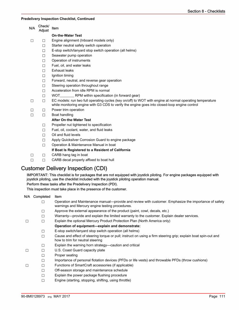
Predelivery Inspection Checklist, Continued
N/A Check/Adjust Item
On‑the‑Water Test⃞ ⃞ Engine alignment (Inboard models only)
⃞ Starter neutral safety switch operation⃞ E‑stop switch/lanyard stop switch operation (all helms)⃞ Seawater pump operation⃞ Operation of instruments⃞ Fuel, oil, and water leaks⃞ Exhaust leaks⃞ Ignition timing⃞ Forward, neutral, and reverse gear operation⃞ Steering operation throughout range⃞ Acceleration from idle RPM is normal⃞ WOT________ RPM within specification (in forward gear)
⃞ ⃞ EC models: run two full operating cycles (key on/off) to WOT with engine at normal operating temperaturewhile monitoring engine with G3 CDS to verify the engine goes into closed‑loop engine control
⃞ ⃞ Power trim operation⃞ ⃞ Boat handling
After On‑the‑Water Test⃞ Propeller nut tightened to specification⃞ Fuel, oil, coolant, water, and fluid leaks⃞ Oil and fluid levels⃞ Apply Quicksilver Corrosion Guard to engine package⃞ Operation & Maintenance Manual in boat
If Boat Is Registered to a Resident of California⃞ ⃞ CARB hang tag in boat⃞ ⃞ CARB decal properly affixed to boat hull
Customer Delivery Inspection (CDI)IMPORTANT: This checklist is for packages that are not equipped with joystick piloting. For engine packages equipped withjoystick piloting, use the checklist included with the joystick piloting operation manual.Perform these tasks after the Predelivery Inspection (PDI).This inspection must take place in the presence of the customer.
N/A Completed Item⃞ Operation and Maintenance manual—provide and review with customer. Emphasize the importance of safety
warnings and Mercury engine testing procedures.⃞ Approve the external appearance of the product (paint, cowl, decals, etc.)⃞ Warranty—provide and explain the limited warranty to the customer. Explain dealer services.
⃞ ⃞ Explain the optional Mercury Product Protection Plan (North America only)Operation of equipment—explain and demonstrate:
⃞ E‑stop switch/lanyard stop switch operation (all helms)⃞ Cause and effect of steering torque or pull; instruct on using a firm steering grip; explain boat spin‑out and
how to trim for neutral steering⃞ Explain the warning horn strategy—caution and critical
⃞ ⃞ U.S. Coast Guard capacity plate⃞ Proper seating⃞ Importance of personal flotation devices (PFDs or life vests) and throwable PFDs (throw cushions)
⃞ ⃞ Functions of SmartCraft accessories (if applicable)⃞ Off‑season storage and maintenance schedule⃞ Explain the power package flushing procedure⃞ Engine (starting, stopping, shifting, using throttle)
Section 8 - Checklists
90-8M0128973 eng MAY 2017 Page 111
N/A Completed Item⃞ Boat (lights, battery switch location, fuses/breakers)
⃞ ⃞ Trailer (if applicable)Registration:
⃞ Complete and submit warranty registration—provide the customer with a copy
Section 8 - Checklists
Page 112 90-8M0128973 eng MAY 2017
Section 9 - Maintenance LogTable of ContentsScheduled Maintenance Log.............................................. 114 Vessel Maintenance Notes................................................. 115
9
Section 9 - Maintenance Log
90-8M0128973 eng MAY 2017 Page 113
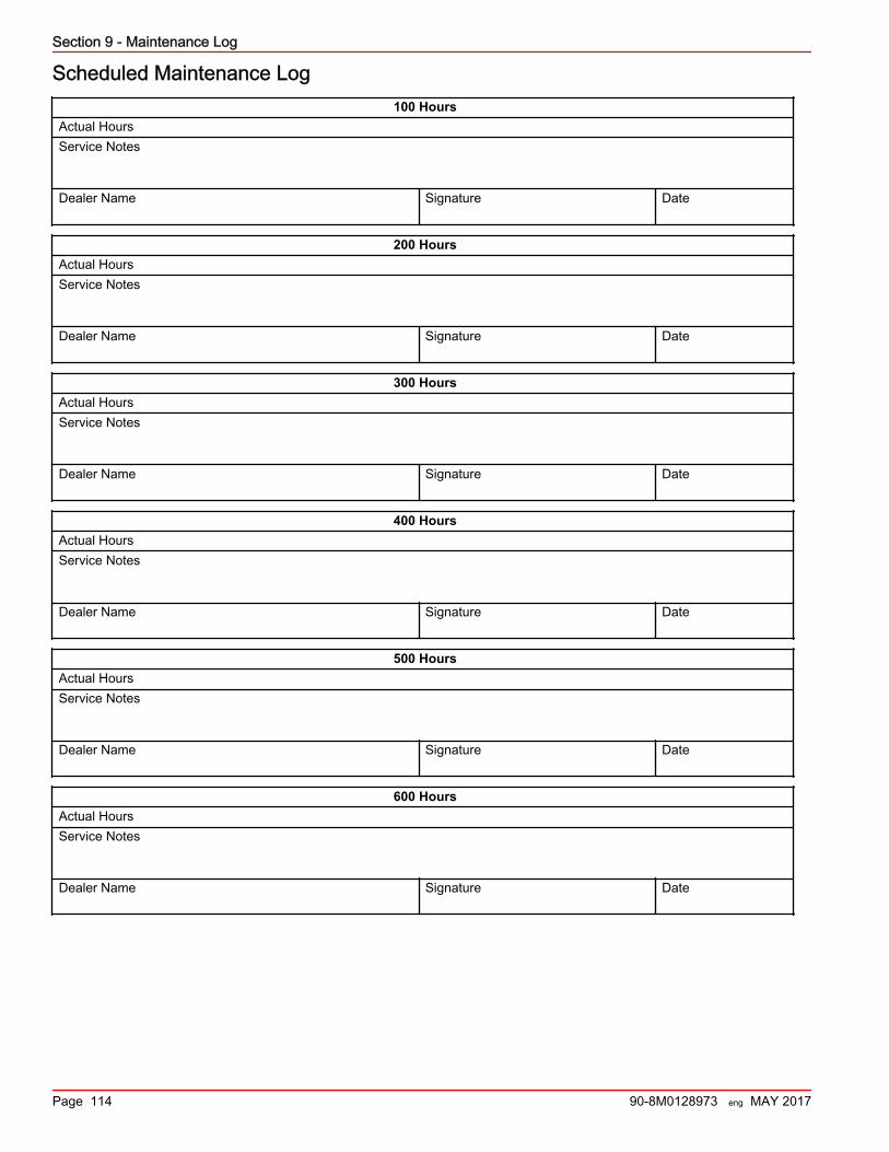
Scheduled Maintenance Log100 Hours
Actual HoursService Notes Dealer Name
Signature
Date
200 HoursActual HoursService Notes Dealer Name
Signature
Date
300 HoursActual HoursService Notes Dealer Name
Signature
Date
400 HoursActual HoursService Notes Dealer Name
Signature
Date
500 HoursActual HoursService Notes Dealer Name
Signature
Date
600 HoursActual HoursService Notes Dealer Name
Signature
Date
Section 9 - Maintenance Log
Page 114 90-8M0128973 eng MAY 2017
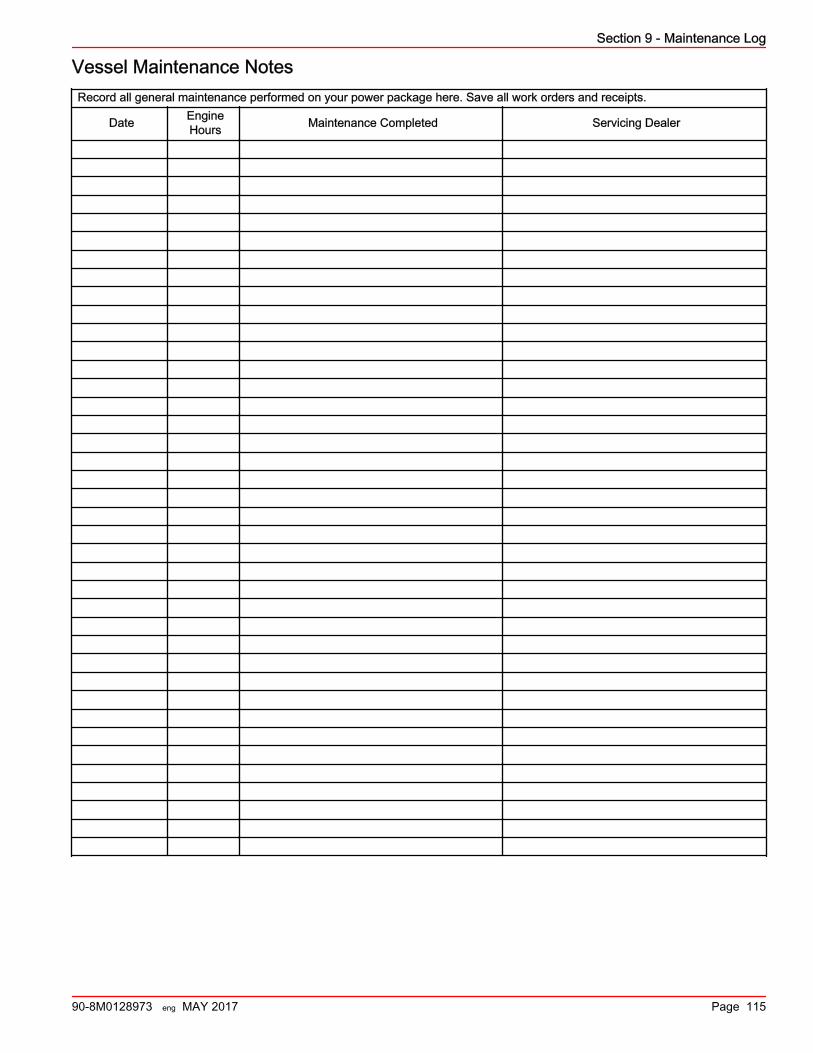
Vessel Maintenance NotesRecord all general maintenance performed on your power package here. Save all work orders and receipts.
Date EngineHours Maintenance Completed Servicing Dealer
Section 9 - Maintenance Log
90-8M0128973 eng MAY 2017 Page 115