Embed Size (px)
Citation preview
Reactor Design Overview
ANSI-NIST Gaithersburg, MD
March 12, 2012 Matt Ales
Component Design Lead Engineer The Babcock & Wilcox Company
© 2012 Generation mPower LLC All rights reserved. 1
Outline
Introduction
Plant Layout
Integral Reactor Design
Safety Features
Technology Development
Codes and Standards
Lead Plant Deployment
Conclusion

© 2012 Generation mPower LLC All rights reserved. 2
Alliance between B&W and Bechtel
Risk sharing with 90/10 current ownership
300+ FTE development team
Technology and project execution
Turnkey projects = cost/schedule certainty
Broad industry engagement
Investment from 15 member Consortium
26 member Industry Advisory Council
Goal is to deploy lead plant by 2020
Industry side of public-private partnership
Platform for industry cost/risk sharing
Nebraska Electric G&T Cooperative
Hoosier Energy Rural Electric Cooperative, Inc.
Generation mPower Industry Consortium
Industry Partners
Industry Advisory Council Includes Consortium members above plus:
AEP Dayton Power & Light Duke Energy Exelon NPPD Vattenfall
Bruce Power Dominion Entergy MidAmerican Progress Energy
www.generationmpower.com
© 2012 Generation mPower LLC All rights reserved. 3
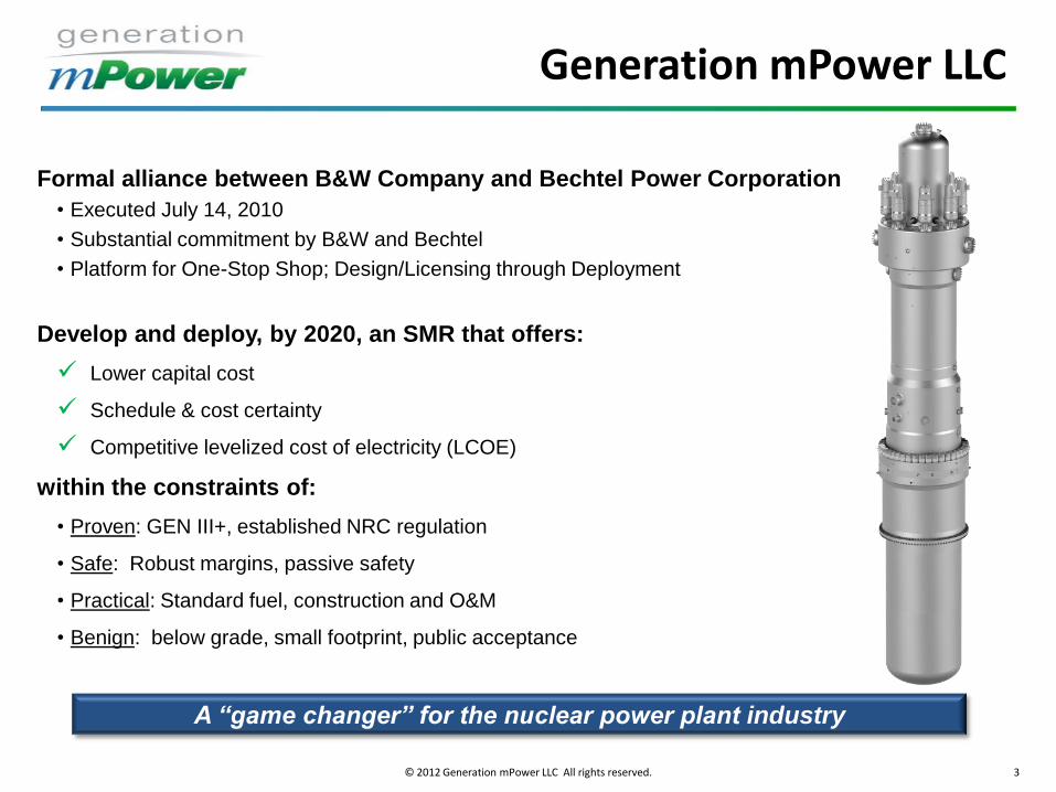
Formal alliance between B&W Company and Bechtel Power Corporation
• Executed July 14, 2010
• Substantial commitment by B&W and Bechtel
• Platform for One-Stop Shop; Design/Licensing through Deployment
Develop and deploy, by 2020, an SMR that offers:
Lower capital cost
Schedule & cost certainty
Competitive levelized cost of electricity (LCOE)
within the constraints of:
• Proven: GEN III+, established NRC regulation
• Safe: Robust margins, passive safety
• Practical: Standard fuel, construction and O&M
• Benign: below grade, small footprint, public acceptance
A “game changer” for the nuclear power plant industry
Generation mPower LLC
© 2012 Generation mPower LLC All rights reserved. 4 .4
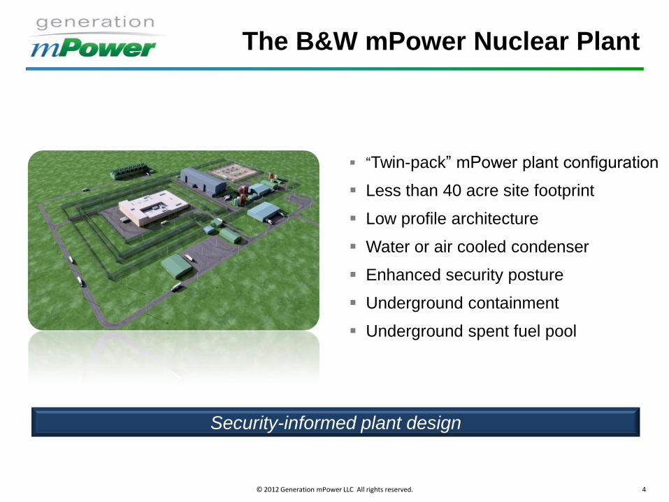
“Twin-pack” mPower plant configuration
Less than 40 acre site footprint
Low profile architecture
Water or air cooled condenser
Enhanced security posture
Underground containment
Underground spent fuel pool
© 2010 Babcock & Wilcox Nuclear Energy, Inc. All rights reserved. Patent Pending
The B&W mPower Nuclear Plant
Security-informed plant design
© 2012 Generation mPower LLC All rights reserved. 5
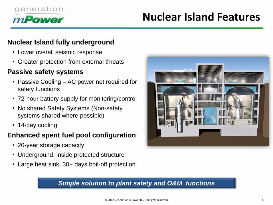
Simple solution to plant safety and O&M functions
Nuclear Island fully underground
• Lower overall seismic response
• Greater protection from external threats
Passive safety systems
• Passive Cooling – AC power not required for
safety functions
• 72-hour battery supply for monitoring/control
• No shared Safety Systems (Non-safety
systems shared where possible)
• 14-day cooling
Enhanced spent fuel pool configuration
• 20-year storage capacity
• Underground, inside protected structure
• Large heat sink, 30+ days boil-off protection
Nuclear Island Features
© 2012 Generation mPower LLC All rights reserved. 6
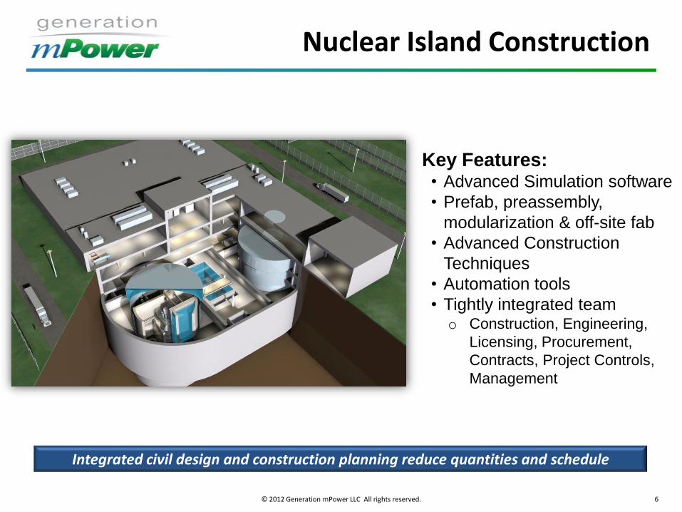
Nuclear Island Construction
Key Features: • Advanced Simulation software
• Prefab, preassembly,
modularization & off-site fab
• Advanced Construction
Techniques
• Automation tools
• Tightly integrated team o Construction, Engineering,
Licensing, Procurement,
Contracts, Project Controls,
Management
Integrated civil design and construction planning reduce quantities and schedule
© 2012 Generation mPower LLC All rights reserved. 7
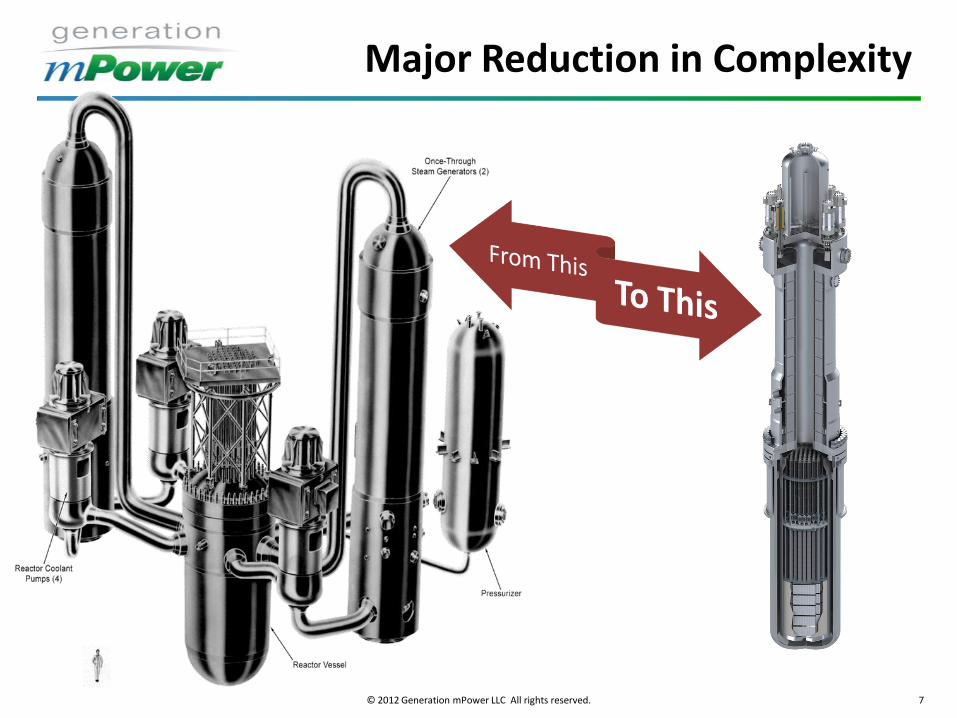
Major Reduction in Complexity
© 2012 Generation mPower LLC All rights reserved. 8
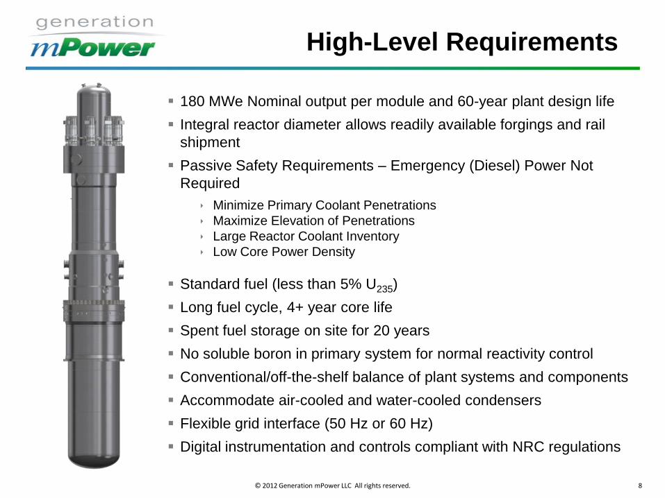
High-Level Requirements
180 MWe Nominal output per module and 60-year plant design life
Integral reactor diameter allows readily available forgings and rail
shipment
Passive Safety Requirements – Emergency (Diesel) Power Not
Required
Minimize Primary Coolant Penetrations
Maximize Elevation of Penetrations
Large Reactor Coolant Inventory
Low Core Power Density
Standard fuel (less than 5% U235)
Long fuel cycle, 4+ year core life
Spent fuel storage on site for 20 years
No soluble boron in primary system for normal reactivity control
Conventional/off-the-shelf balance of plant systems and components
Accommodate air-cooled and water-cooled condensers
Flexible grid interface (50 Hz or 60 Hz)
Digital instrumentation and controls compliant with NRC regulations
© 2012 Generation mPower LLC All rights reserved. 9
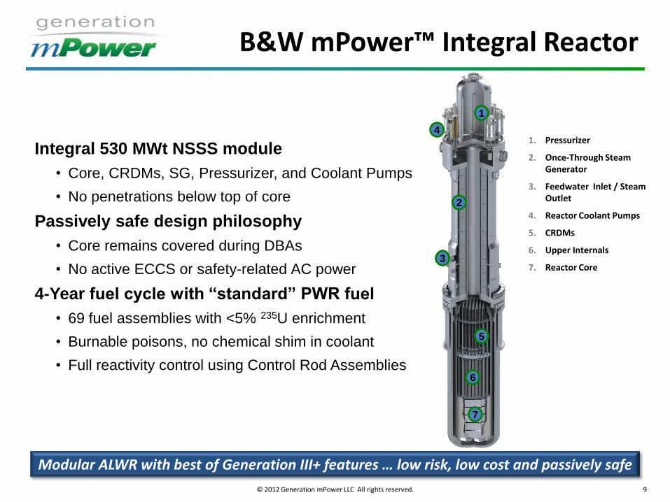
Integral 530 MWt NSSS module
• Core, CRDMs, SG, Pressurizer, and Coolant Pumps
• No penetrations below top of core
Passively safe design philosophy
• Core remains covered during DBAs
• No active ECCS or safety-related AC power
4-Year fuel cycle with “standard” PWR fuel
• 69 fuel assemblies with <5% 235U enrichment
• Burnable poisons, no chemical shim in coolant
• Full reactivity control using Control Rod Assemblies
Modular ALWR with best of Generation III+ features … low risk, low cost and passively safe
1. Pressurizer
2. Once-Through Steam Generator
3. Feedwater Inlet / Steam Outlet
4. Reactor Coolant Pumps
5. CRDMs
6. Upper Internals
7. Reactor Core
1
2
3
4
5
6
7
B&W mPower™ Integral Reactor
© 2012 Generation mPower LLC All rights reserved. 10
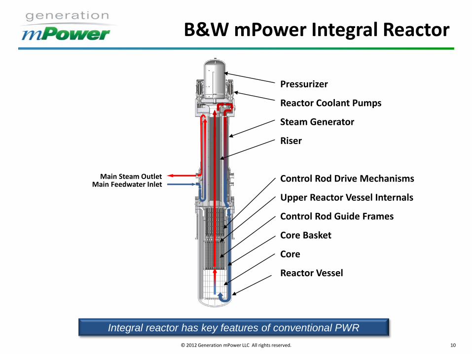
Integral reactor has key features of conventional PWR
Main Steam Outlet Main Feedwater Inlet
Pressurizer
Reactor Coolant Pumps
Steam Generator
Riser
Control Rod Drive Mechanisms
Upper Reactor Vessel Internals
Control Rod Guide Frames
Core Basket
Core
Reactor Vessel
B&W mPower Integral Reactor
© 2012 Generation mPower LLC All rights reserved. 11 Secondary
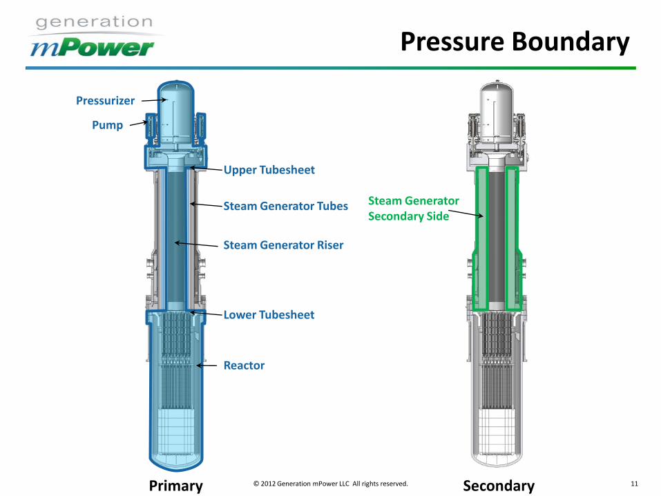
Steam Generator Secondary Side
Primary
Pump
Steam Generator Riser
Reactor
Steam Generator Tubes
Upper Tubesheet
Lower Tubesheet
Pressurizer
Pressure Boundary
© 2012 Generation mPower LLC All rights reserved. 12
Feature B&W 177 Typical Gen 3 PWR
B&W mPower
Feature B&W 177 Typical Gen 3 PWR
B&W mPower
Rated Core power (MWth) 2568 3415 425
Core average linear heat rate (kWth/m) 18.7 18.7 11.5
Average flow velocity through the core
(m/s)
4.8 4.8 2.5
RCS volume (m3) 325 272 91
RCS volume to power ratio (m3/MWth) 0.14 0.08 0.21
Maximum LOCA area (m2) * 1.3 1.0 0.009
* Assumes double ended break
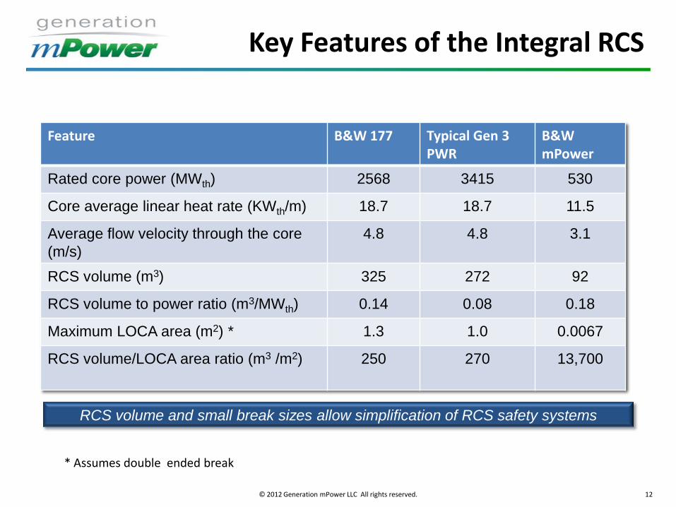
RCS volume and small break sizes allow simplification of RCS safety systems
Feature B&W 177 Typical Gen 3 PWR
B&W mPower
Rated core power (MWth) 2568 3415 530
Core average linear heat rate (KWth/m) 18.7 18.7 11.5
Average flow velocity through the core
(m/s)
4.8 4.8 3.1
RCS volume (m3) 325 272 92
RCS volume to power ratio (m3/MWth) 0.14 0.08 0.18
Maximum LOCA area (m2) * 1.3 1.0 0.0067
RCS volume/LOCA area ratio (m3 /m2) 250 270 13,700
Key Features of the Integral RCS
© 2012 Generation mPower LLC All rights reserved. 13
• 69 fuel assemblies
• < 5 wt% 235U enrichments
• No soluble boron for control
• Axially graded BPRs
• Gd2O3 spiked rods
• Control rod sequence exchanges
• AIC and B4C control rods
• 3% shutdown margin
Core Design Features
© 2012 Generation mPower LLC All rights reserved. 14 14
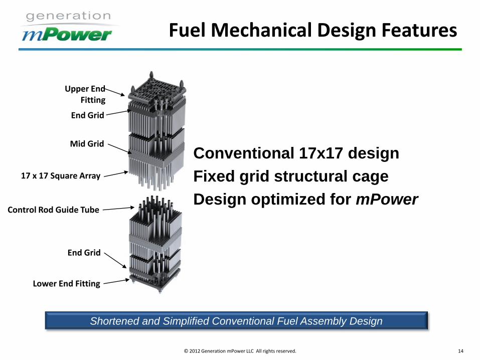
Shortened and Simplified Conventional Fuel Assembly Design
Conventional 17x17 design
Fixed grid structural cage
Design optimized for mPower
Upper End Fitting
End Grid
Mid Grid
17 x 17 Square Array
Control Rod Guide Tube
End Grid
Lower End Fitting
Fuel Mechanical Design Features

© 2012 Generation mPower LLC All rights reserved. 15 .15
Low Core Linear Heat Rate
• Low power density reduces fuel and clad temperatures during
accidents
• Low power density allows lower flow velocities that minimize flow
induced vibration effects
Large Reactor Coolant System Volume
• Large RCS volume allows more time for safety system response in
the event of an accident
• More coolant is available during a small break LOCA providing
continuous cooling to protect the core
Small Penetrations at High Elevation
• High penetration locations increase the amount of coolant left in the
vessel after a LOCA
• Small penetrations reduce rate of energy release to containment
resulting in lower containment pressures
CONFIDENTIAL AND PROPRIETARY TO B&W
Inherent Safety Features
© 2012 Generation mPower LLC All rights reserved. 16
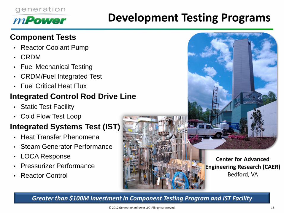
Center for Advanced Engineering Research (CAER)
Bedford, VA
Greater than $100M Investment in Component Testing Program and IST Facility
Component Tests
• Reactor Coolant Pump
• CRDM
• Fuel Mechanical Testing
• CRDM/Fuel Integrated Test
• Fuel Critical Heat Flux
Integrated Control Rod Drive Line
• Static Test Facility
• Cold Flow Test Loop
Integrated Systems Test (IST)
• Heat Transfer Phenomena
• Steam Generator Performance
• LOCA Response
• Pressurizer Performance
• Reactor Control
Development Testing Programs
© 2012 Generation mPower LLC All rights reserved. 17
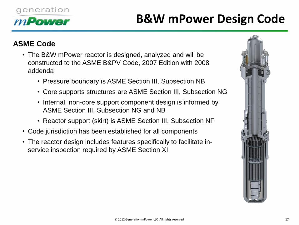
ASME Code
• The B&W mPower reactor is designed, analyzed and will be
constructed to the ASME B&PV Code, 2007 Edition with 2008
addenda
• Pressure boundary is ASME Section III, Subsection NB
• Core supports structures are ASME Section III, Subsection NG
• Internal, non-core support component design is informed by
ASME Section III, Subsection NG and NB
• Reactor support (skirt) is ASME Section III, Subsection NF
• Code jurisdiction has been established for all components
• The reactor design includes features specifically to facilitate in-
service inspection required by ASME Section XI
B&W mPower Design Code
© 2012 Generation mPower LLC All rights reserved. 18
mPower Overviews for ASME
• mPower Reactor Overviews for ASME
Keep ASME informed of mPower reactor design
• Recent Presentations
ASME Executive Committee on Strategy (8/11/11)
ASME 2011 SMR Symposium, Plenary Session (9/29/11)
ASME Overview presentation to NRC (11/17/11)
Overview presentation to Section XI (2/6/12)
• ASME Feedback
Encouraged B&W to continue apprising them of the design
Eager to resolve any potential ASME standards issues
© 2012 Generation mPower LLC All rights reserved. 19
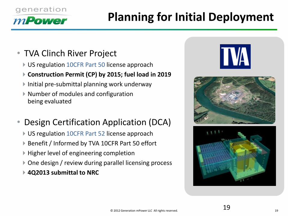
Planning for Initial Deployment
• TVA Clinch River Project US regulation 10CFR Part 50 license approach
Construction Permit (CP) by 2015; fuel load in 2019
Initial pre-submittal planning work underway
Number of modules and configuration being evaluated
• Design Certification Application (DCA) US regulation 10CFR Part 52 license approach
Benefit / Informed by TVA 10CFR Part 50 effort
Higher level of engineering completion
One design / review during parallel licensing process
4Q2013 submittal to NRC
19
© 2012 Generation mPower LLC All rights reserved. 20
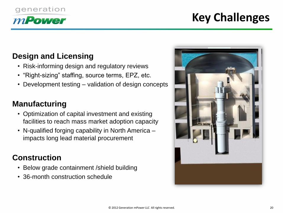
Key Challenges
Design and Licensing
• Risk-informing design and regulatory reviews
• “Right-sizing” staffing, source terms, EPZ, etc.
• Development testing – validation of design concepts
Manufacturing
• Optimization of capital investment and existing
facilities to reach mass market adoption capacity
• N-qualified forging capability in North America –
impacts long lead material procurement
Construction
• Below grade containment /shield building
• 36-month construction schedule
© 2012 Generation mPower LLC All rights reserved. 21
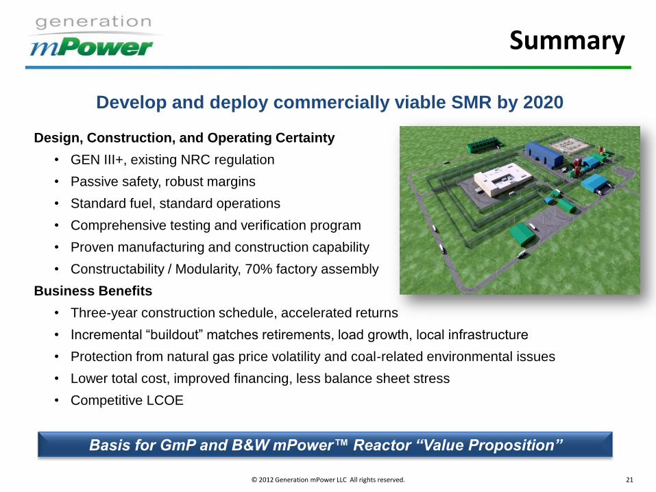
Summary
Develop and deploy commercially viable SMR by 2020
Design, Construction, and Operating Certainty
• GEN III+, existing NRC regulation
• Passive safety, robust margins
• Standard fuel, standard operations
• Comprehensive testing and verification program
• Proven manufacturing and construction capability
• Constructability / Modularity, 70% factory assembly
Business Benefits
• Three-year construction schedule, accelerated returns
• Incremental “buildout” matches retirements, load growth, local infrastructure
• Protection from natural gas price volatility and coal-related environmental issues
• Lower total cost, improved financing, less balance sheet stress
• Competitive LCOE
Basis for GmP and B&W mPower™ Reactor “Value Proposition”
Questions?