Embed Size (px)
Citation preview
reader application The final measured and simulated results
show satisfactory performance and good agreement
REFERENCES
1 DH Lee PJ Park JP Kim and JH Choi Aperture coupled UHF
RFID reader antenna for a handheld application Microwave Opt
Technol Lett 50 (2008) 1261ndash1263
2 YF Lin HM Chen SC Pan YC Kao and CY Lin Adjustable
axial ratio of single-layer circularly polarised patch antenna for port-
able RFID reader Electron Lett 45 (2009) 290ndash292
3 HH Li XQ Mou Z Ji H Yu Y Li and L Jiang Miniature
RFID tri-band CPW-fed antenna optimised using ISPO algorithm
Electron Lett 47 (2011) 161ndash162
4 CJ Wang and YC Lin New CPW-fed monopole antennas with
both linear and circular polarisations IET Microwave Antennas
Propag 2 (2008) 466ndash472
5 JW Wu JY Ke CF Jou and CJ Wang Microstrip-fed broad-
band circularly polarized monopole antenna IET Microwave Anten-
nas Propag 4 (2010) 518ndash525
6 A Ghobadi and M Dehmollaian A printed circularly polarized Y-
shaped monopole antenna IEEE Antenna Wireless Propag Lett 11
(2012) 22ndash25
7 JY Jan and LC Tseng Small planar monopole antenna with a
shorted parasitic inverted-L wire for wireless communications in the
24- 52- and 58-GHz bands IEEE Trans Antennas Propag 52
(2004) 1903ndash1905
VC 2014 Wiley Periodicals Inc
RADIATION-REJECTION BANDINSERTED DUAL-BAND ANTENNAUSING A SPLIT RING RESONATORFOR BEYOND 4G APPLICATIONS
In-Yong Park1 Jung-Nam Lee2 Kwang-Chun Lee2
Pyeong-Jung Song2 and Dongho Kim1
1 Department of Electronic Engineering Sejong University 209Neungdong-ro Gwangjin-gu Seoul 143ndash747 Korea Correspondingauthor dongkimsejongackr2 Department of B4G Mobile Communications Research Electronicsand Telecommunications Research Institute 218 Gajeong-roYuseong-gu Daejeon 305-700 Korea
Received 8 August 2013
ABSTRACT We propose a very simple but effective method to switcha single-band antenna into a dual-band antenna by inserting a narrow
radiation-prohibited band in the middle of the single pass band Toinsert the radiation-rejection band we intentionally induce strong reso-nance on a metamaterial-motivated split ring resonator (SRR) by placing
it near a signal feeding transmission line of a proximity-coupled micro-strip patch antenna which blocks out flow of electromagnetic wavesthrough the line To maximize the blockage we cut the SRR into a quad-
rangular loop that is exactly interlocked with the two sides of the right-angled microstrip line Consequently we show that we can split one
pass band into two separated pass bands with an inserted sharp stopband in-between Good agreements between the prediction and the mea-surement prove the validness of our approach VC 2014 Wiley
Periodicals Inc Microwave Opt Technol Lett 56961ndash965 2014 View
this article online at wileyonlinelibrarycom DOI 101002mop28240
Key words radiation-rejection band guard band B4G antenna split
ring resonator
1 INTRODUCTION
Recently mobile communication services have dramatically
evolved to the current fourth generation (4G) system that is rep-
resented by long-term evolution (LTE) or LTE-advanced tech-
nology Currently to support an expected explosive increase of
data transmission speed and cell capacity in future mobile com-
munication environment ongoing study continuously extends its
research areas beyond 4G (B4G) systems [1]
In accordance with evolution of the mobile communication
environment mobile base station antenna (MBSA) technology
has also been developed rapidly As one prominent approach of
useful MBSA techniques inserting a guard band which is a sort
of suppressed radiation frequency band has been reported to
reduce interference between transmitter and receiver systems [2]
With regard to generation of the guard band installing an
artificial magnetic conductor (AMC) or an electromagnetic
(EM) band gap (EBG) material which is incorporated with an
adjacent main radiator is representative conventional approach
[2ndash4] Although the mentioned approaches are fairly effective in
reducing antenna gain in the guard band they generally require
additional layers or spaces to mount AMCs or EBG structures
which increases complexity and fabrication cost of antennas
To overcome the problems we propose a very simple but
valuable method to create a radiation-prohibited guard band
using a split ring resonator (SRR) which is well-known as one
of left-handed metamaterial structures [5 6] As was reported in
[7 8] strong energy coupling between a transmission line and a
nearby scatterer blocks energy transfer through the line The
strength of the energy blockage is proportional to a total number
of scatterers installed near the line which often becomes an
obstructive factor in practical implementation especially under
circumstances of requiring strong blockage with only a limited
small installation space
In spite of the well-known drawbacks in this article we
show that we can introduce a guard band in an existing pass
band by placing only one SRR near a bent microstrip line
which provides relatively high radiation-rejection property For
experimental verification we apply our idea to a dual-band base
station antenna for a B4G mobile communication service which
has a target frequency band covering from 25 to 2695 GHz
(Rx 25ndash252 GHz and Tx 2675ndash2 695 GHz) All simulation
data are obtained using the commercial simulation tool of CST
Microwave Studio [9]
2 ANTENNA DESIGN
Figure 1 shows the exploded view of the proposed antenna For
polarization diversity of 90 we arrange two signal-feed lines
orthogonally with each other which are shown in Figure 1(a)
Each end of the lines is directly connected to a 50-X coaxial
connector using a direct probe feeding method EM waves flow-
ing along the feed lines couple to the radiating patch shown in
Figure 1(b) which accomplishes proximity coupling from the
lines onto the radiating patch [10 11]
As was aforementioned one of the target applications of our
antenna is a base station antenna required for B4G communica-
tions which usually needs multiple stacks of the proposed
antennas to meet the desired performance of mobile cells under
various operational environments Therefore isolation among
antennas should be secured as highly as possible For that rea-
son we enclosed our antenna with a metallic cavity as shown in
Figure 1(c) which is covered by a top radome As a result
besides high isolation we can also increase both realized gain
and front-to-back ratio (FBR) up to about 7 and 25 dBi (see
Figs 6 and 7) respectively
In Figure 1(a) we can find two SRRs placed near each corner
of the feed lines which are installed to introduce a very narrow
DOI 101002mop MICROWAVE AND OPTICAL TECHNOLOGY LETTERS Vol 56 No 4 April 2014 961
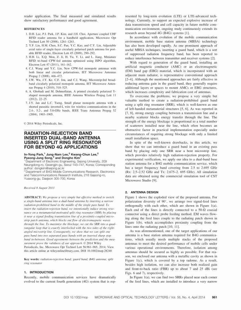
stop band into a wide pass band Figure 2(a) tells us how we can
get the very sharp stop band by placing the SRR closed to a nor-
mal microstrip line EM waves propagate into Port 2 along a 50-
X microstrip line etched on the same substrate used in Figure
1(a) When we put the SRR near the line the SRR resonates at a
specific frequency at which the circumferential length of the SRR
becomes about a half of a guided wavelength At the resonant
frequency the SRR strongly resonates as shown in the inset in
Figure 2(a) which conceptually illustrates flowing of induced sur-
face current density The thicker and the longer arrows mean the
stronger current density From Figure 2(b) it is worth noting that
we can change the bandwidth of S11 by increasing or decreasing
the gap distance (g1) between the microstrip line and the SRR
which can be explained by parasitic inductance and capacitance
[12] In other words we can control any radiation-rejection band-
width by changing the distance g1
Figure 1 Geometry of the proposed antenna for (a) signal-feed lines (b) a radiating patch and (c) a side view of a whole structure with wx 5 70 mm
wy 5 70 mm w1 5 63 mm w2 5 1 mm w3 5 80 mm l6 5 37 mm l5 5 19 mm l1 5 37 mm l2 5 29 mm l3 5 973 mm l4 5 902 mm g1 5 3 mm
g2 5 1 mm g3 5 23 mm g4 5 14 mm h1 5 30 mm h2 5 17 mm h3 5 4 mm d1 5 16 mm d2 5 2 mm er1 5 er2 5 43 and er3 5 35
Figure 2 Resonance property of the proposed MTM structure with (a) induced surface current density and (b) S11 for some different gap distances
(g1) Physical dimension of the SRR is exactly the same with that used in Figure 1(a) [Color figure can be viewed in the online issue which is available
at wileyonlinelibrarycom]
962 MICROWAVE AND OPTICAL TECHNOLOGY LETTERS Vol 56 No 4 April 2014 DOI 101002mop
The resonance can be explained by strong energy coupling
from the line to the SRR which blocks transfer of almost all
energy through the line Thus we can introduce a very narrow
stop band into a single wide pass band Consequently from the
remarkably reduced signal transmittance we can naturally
expect that much less power will be radiated through the
antenna shown in Figure 1
There are two important features that should be pointed out
one is that we can place a sharp stop band in an existing pass
band with almost no change in overall antenna performance
such as impedance matching bandwidth and antenna gain and
so forth In other words we can make the antenna operate as a
single-band antenna just by eliminating the SRRs without any
change in antenna geometry and properties The other is sim-
plicity in implementation To maximize energy blockage we
intentionally bend the feed lines at a right angle which is help-
ful to increase interlocked lengths between the SRR and the
line Consequently only one small SRR is sufficient to effec-
tively block waves Hence additional layers are totally
unnecessary which are often unavoidable when we use con-
ventional AMC or EBG structures for a similar band separation
approach
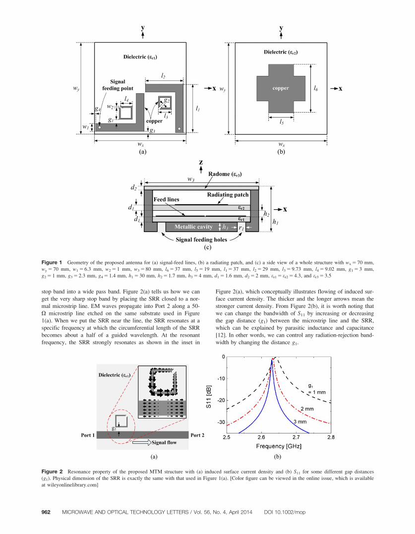
Figure 3 Photograph of the proposed antenna (a) the signal-feed lines (b) the radiating patch and (c) the whole structure assembled in a metallic
cavity [Color figure can be viewed in the online issue which is available at wileyonlinelibrarycom]
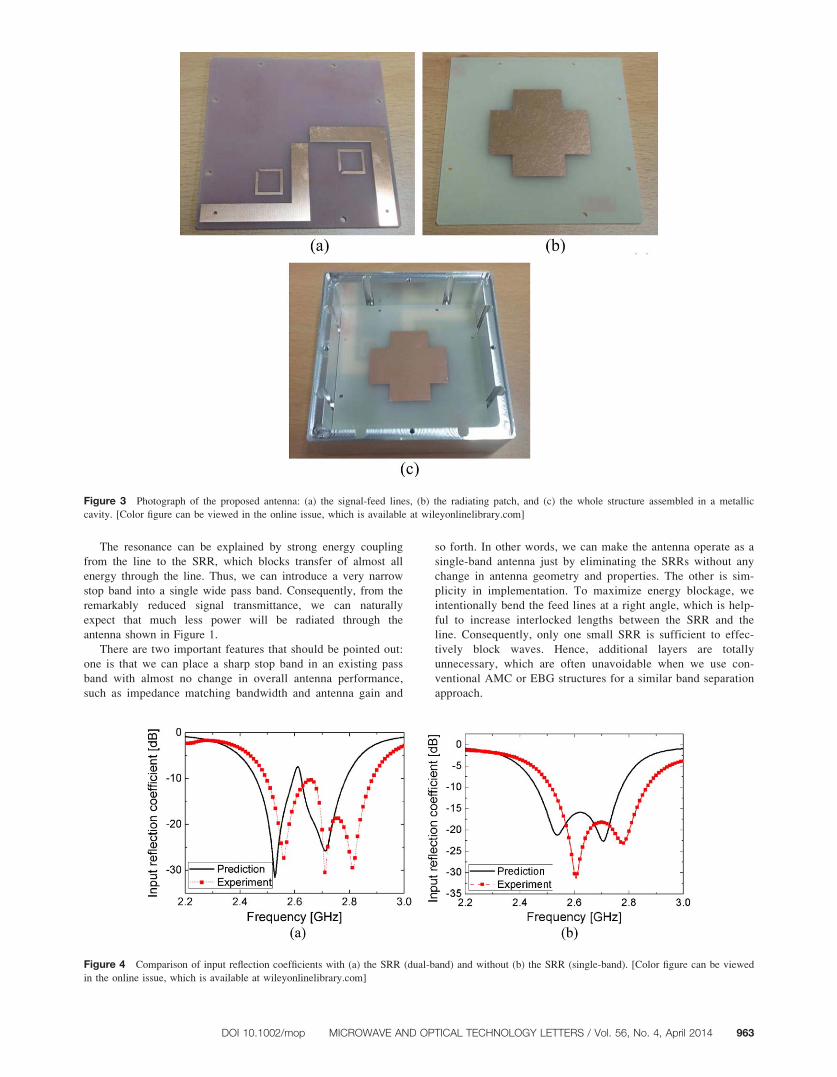
Figure 4 Comparison of input reflection coefficients with (a) the SRR (dual-band) and without (b) the SRR (single-band) [Color figure can be viewed
in the online issue which is available at wileyonlinelibrarycom]
DOI 101002mop MICROWAVE AND OPTICAL TECHNOLOGY LETTERS Vol 56 No 4 April 2014 963
3 FABRICATION AND EXPERIMENTS
The fabricated components of the proposed antenna are given
in Figure 3 Even though the figure is only about the dual-
band antenna every elements of the single-band antenna are
exactly the same as those shown in Figure 3 except for the
SRRs
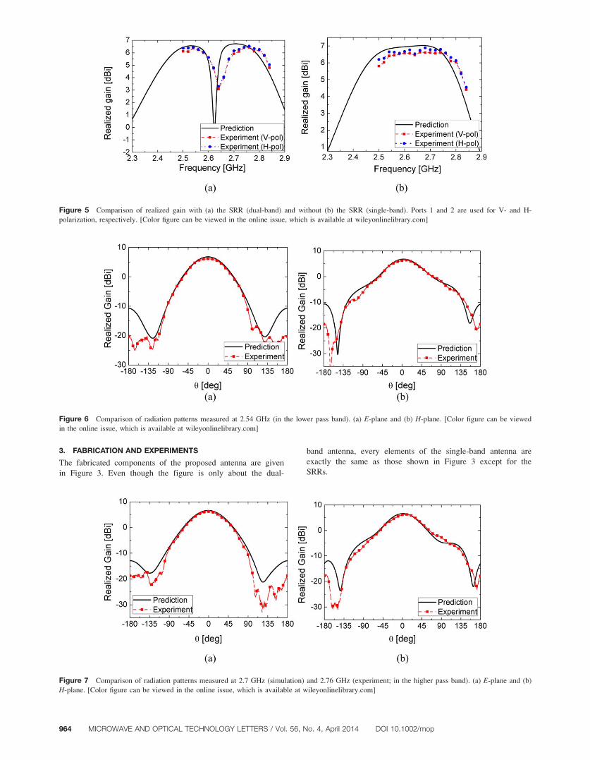
Figure 5 Comparison of realized gain with (a) the SRR (dual-band) and without (b) the SRR (single-band) Ports 1 and 2 are used for V- and H-
polarization respectively [Color figure can be viewed in the online issue which is available at wileyonlinelibrarycom]
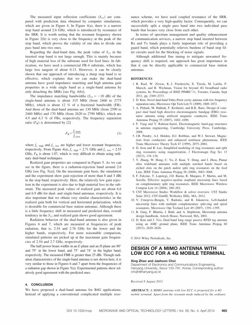
Figure 6 Comparison of radiation patterns measured at 254 GHz (in the lower pass band) (a) E-plane and (b) H-plane [Color figure can be viewed
in the online issue which is available at wileyonlinelibrarycom]
Figure 7 Comparison of radiation patterns measured at 27 GHz (simulation) and 276 GHz (experiment in the higher pass band) (a) E-plane and (b)
H-plane [Color figure can be viewed in the online issue which is available at wileyonlinelibrarycom]
964 MICROWAVE AND OPTICAL TECHNOLOGY LETTERS Vol 56 No 4 April 2014 DOI 101002mop
The measured input reflection coefficients (S11) are com-
pared with prediction data obtained by computer simulations
which are given in Figure 4 In Figure 4(a) there is a narrow
stop band around 26 GHz which is introduced by resonance of
the SRR It is worth noting that the resonant frequency shown
in Figure 2(b) is very close to the frequency at the peak of the
stop band which proves the validity of our idea to divide one
pass band into two ones
Regarding the dual-band data the peak value of S11 in the
inserted stop band is not large enough This is mainly because
of high material loss of the substrate used for feed lines In fab-
rication we have used a commercial FR-4 substrate which has
large loss tangent of about 013 However it can be clearly
shown that our approach of introducing a sharp stop band is so
effective which explains that we can make the dual-band
antenna have good impedance matching and high antenna gain
properties in a wide single band as a single-band antenna by
only detaching the SRRs [see Fig 4(b)]
The impedance matching bandwidths (S11 5 210 dB) of the
single-band antenna is about 315 MHz (from 2460 to 2775
MHz) which is about 12 of a fractional bandwidth (FB)
And those of the dual-band antenna are 130 MHz (from 2590 to
2460 MHz) and 170 MHz (from 2620 to 2790 MHz) which are
49 and 63 of FBs respectively The frequency separation
ratio (FR) is determined by [2]
FR5fchigh
fclow
(1)
where fc high and fc low are higher and lower resonant frequencies
respectively From Figure 4(a) fc high 5 271 GHz and fc low 5 253
GHz FR is about 107 which is very difficult to obtain using ordi-
nary dual-band techniques
Realized gain properties are compared in Figure 5 As we can
see in the figure there is a radiation-rejection band around 26
GHz [see Fig 5(a)] On the maximum gain basis the simulation
and the experiment show gain rejection of more than 8 and 3 dBi
in the stop band respectively Here the relatively low gain rejec-
tion in the experiment is also due to high material loss in the sub-
strate The measured peak values of realized gain are about 66
and 69 dBi for dual- and single-band antennas respectively It is
also important that we obtain very similar characteristics in the
realized gain both for vertical and horizontal polarization which
is desirable for commercial base station antennas Although there
is a little frequency shift in measured and predicted data overall
tendency in the S11 and realized gain shows good agreement
Radiation behavior of the dual-band antenna is also given in
Figures 6 and 7 which are measured at frequencies of peak
radiation that is 254 and 276 GHz for the lower and the
higher bands respectively For more reasonable comparison
simulated patterns are picked up at the maximum gain frequen-
cies of 254 and 27 GHz respectively
The half power beam widths in an E-plane and an H-plane are 80
and 79 in the lower band and 75 and 74 in the higher band
respectively The measured FBR is greater than 25 dBi Though radi-
ation characteristics of the single-band antenna is not shown here it is
very similar to those in Figures 6 and 7 apart from the frequencies of
a radiation gap shown in Figure 5(a) Experimental patterns show rel-
atively good agreement with the predicted ones
4 CONCLUSION
We have proposed a dual-band antenna for B4G applications
Instead of applying a conventional complicated multiple reso-
nance scheme we have used coupled resonance of the SRR
which provides a very high-quality factor Consequently we can
successfully split a single pass band into two individual pass
bands that locates very close from each other
In terms of spectrum management and quality enhancement
of communication services a narrow stop band inserted between
Rx and Tx bands plays a fairly important role of providing a
guard band which potentially relieves burdens of band stop fil-
ter circuits used for the blocking of noise signals
Although additional fine tuning to mitigate unwanted fre-
quency shift is required our approach has great importance in
that it can be directly applicable to commercial base station
antennas
REFERENCES
1 B Raaf W Zirwas K-J Friederichs E Tiirola M Laitila P
Marsch and R Wichman Vision for beyond 4G broadband radio
systems In Proceedings of IEEE PIMRCrsquo11 Toronto Canada Sept
2011 pp 2369ndash2373
2 D Kim Novel dual-band Fabry-Perot cavity antenna with low frequency
separation ratio Microwave Opt Tech Lett 51 (2009) 1869ndash1872
3 A Pirhadi M Hakkak F Keshmiri and RK Baee Design of com-
pact dual band high directive electromagnetic bandgap (EBG) reso-
nator antenna using artificial magnetic conductor IEEE Trans
Antennas Propag 55 (2007) 1682ndash1690
4 F Yang and Y Rahmat-Samii Electromagnetic band-gap structures
in antenna engineering Cambridge University Press Cambridge
2008
5 JB Pendry AJ Holden DJ Robbins and WJ Stewart Magne-
tism from conductors and enhanced nonlinear phenomena IEEE
Trans Microwave Theory Tech 47 (1999) 2075ndash2084
6 D Jeon and B Lee Simplified modeling of ring resonators and split
ring resonators using magnetization J Electromagn Eng Sci 13
(2013) 134ndash136
7 Y Zhang W Hong C Yu Z Kuai Y Dong and J Zhou Planar
ultra wideband antennas with multiple notched bands based on
etched slots on the patch andor split ring resonators on the feed
Line IEEE Trans Antennas Propag 56 (2008) 3063ndash3068
8 F Falcone T Lopetegi JD Baena R Marques F Martin and M
Sorolla Effective negative-epsilon stopband microstrip lines based
on complementary split ring resonators IEEE Microwave Wireless
Compon Lett 14 (2004) 280ndash282
9 CST Microwave Studio Workflow amp solver overview CST Studio
Suite 2012 CST-GmbH Wellesley Hills MA 2012
10 V Crnojevic-Bengin V Radonic and B Jokanovic Left-handed
microstrip lines with multiple complementary split-ring and spiral
resonators Microwave Opt Technol Lett 49 (2007) 1391ndash1395
11 R Garg P Bhartia I Bahl and A Ittipiboon Microstrip antenna
design handbook Artech House Norwood MA 2001
12 D Kim and J Yeo Dual-band long range passive RFID tag antenna
using an AMC ground plane IEEE Trans Antennas Propag 60
(2012) 2620ndash2626
VC 2014 Wiley Periodicals Inc
DESIGN OF A MIMO ANTENNA WITHLOW ECC FOR A 4G MOBILE TERMINAL
Xing Zhao and Jaehoon ChoiDepartment of Electronics and Communications EngineeringHanyang University Seoul 133ndash791 Korea Corresponding authorchoijhhanyangackr
Received 8 August 2013
ABSTRACT A MIMO antenna with low ECC is proposed for a 4G
mobile terminal Apart from the resonant mode induced by the ordinary
DOI 101002mop MICROWAVE AND OPTICAL TECHNOLOGY LETTERS Vol 56 No 4 April 2014 965
stop band into a wide pass band Figure 2(a) tells us how we can
get the very sharp stop band by placing the SRR closed to a nor-
mal microstrip line EM waves propagate into Port 2 along a 50-
X microstrip line etched on the same substrate used in Figure
1(a) When we put the SRR near the line the SRR resonates at a
specific frequency at which the circumferential length of the SRR
becomes about a half of a guided wavelength At the resonant
frequency the SRR strongly resonates as shown in the inset in
Figure 2(a) which conceptually illustrates flowing of induced sur-
face current density The thicker and the longer arrows mean the
stronger current density From Figure 2(b) it is worth noting that
we can change the bandwidth of S11 by increasing or decreasing
the gap distance (g1) between the microstrip line and the SRR
which can be explained by parasitic inductance and capacitance
[12] In other words we can control any radiation-rejection band-
width by changing the distance g1
Figure 1 Geometry of the proposed antenna for (a) signal-feed lines (b) a radiating patch and (c) a side view of a whole structure with wx 5 70 mm
wy 5 70 mm w1 5 63 mm w2 5 1 mm w3 5 80 mm l6 5 37 mm l5 5 19 mm l1 5 37 mm l2 5 29 mm l3 5 973 mm l4 5 902 mm g1 5 3 mm
g2 5 1 mm g3 5 23 mm g4 5 14 mm h1 5 30 mm h2 5 17 mm h3 5 4 mm d1 5 16 mm d2 5 2 mm er1 5 er2 5 43 and er3 5 35
Figure 2 Resonance property of the proposed MTM structure with (a) induced surface current density and (b) S11 for some different gap distances
(g1) Physical dimension of the SRR is exactly the same with that used in Figure 1(a) [Color figure can be viewed in the online issue which is available
at wileyonlinelibrarycom]
962 MICROWAVE AND OPTICAL TECHNOLOGY LETTERS Vol 56 No 4 April 2014 DOI 101002mop
The resonance can be explained by strong energy coupling
from the line to the SRR which blocks transfer of almost all
energy through the line Thus we can introduce a very narrow
stop band into a single wide pass band Consequently from the
remarkably reduced signal transmittance we can naturally
expect that much less power will be radiated through the
antenna shown in Figure 1
There are two important features that should be pointed out
one is that we can place a sharp stop band in an existing pass
band with almost no change in overall antenna performance
such as impedance matching bandwidth and antenna gain and
so forth In other words we can make the antenna operate as a
single-band antenna just by eliminating the SRRs without any
change in antenna geometry and properties The other is sim-
plicity in implementation To maximize energy blockage we
intentionally bend the feed lines at a right angle which is help-
ful to increase interlocked lengths between the SRR and the
line Consequently only one small SRR is sufficient to effec-
tively block waves Hence additional layers are totally
unnecessary which are often unavoidable when we use con-
ventional AMC or EBG structures for a similar band separation
approach
Figure 3 Photograph of the proposed antenna (a) the signal-feed lines (b) the radiating patch and (c) the whole structure assembled in a metallic
cavity [Color figure can be viewed in the online issue which is available at wileyonlinelibrarycom]
Figure 4 Comparison of input reflection coefficients with (a) the SRR (dual-band) and without (b) the SRR (single-band) [Color figure can be viewed
in the online issue which is available at wileyonlinelibrarycom]
DOI 101002mop MICROWAVE AND OPTICAL TECHNOLOGY LETTERS Vol 56 No 4 April 2014 963
3 FABRICATION AND EXPERIMENTS
The fabricated components of the proposed antenna are given
in Figure 3 Even though the figure is only about the dual-
band antenna every elements of the single-band antenna are
exactly the same as those shown in Figure 3 except for the
SRRs
Figure 5 Comparison of realized gain with (a) the SRR (dual-band) and without (b) the SRR (single-band) Ports 1 and 2 are used for V- and H-
polarization respectively [Color figure can be viewed in the online issue which is available at wileyonlinelibrarycom]
Figure 6 Comparison of radiation patterns measured at 254 GHz (in the lower pass band) (a) E-plane and (b) H-plane [Color figure can be viewed
in the online issue which is available at wileyonlinelibrarycom]
Figure 7 Comparison of radiation patterns measured at 27 GHz (simulation) and 276 GHz (experiment in the higher pass band) (a) E-plane and (b)
H-plane [Color figure can be viewed in the online issue which is available at wileyonlinelibrarycom]
964 MICROWAVE AND OPTICAL TECHNOLOGY LETTERS Vol 56 No 4 April 2014 DOI 101002mop
The measured input reflection coefficients (S11) are com-
pared with prediction data obtained by computer simulations
which are given in Figure 4 In Figure 4(a) there is a narrow
stop band around 26 GHz which is introduced by resonance of
the SRR It is worth noting that the resonant frequency shown
in Figure 2(b) is very close to the frequency at the peak of the
stop band which proves the validity of our idea to divide one
pass band into two ones
Regarding the dual-band data the peak value of S11 in the
inserted stop band is not large enough This is mainly because
of high material loss of the substrate used for feed lines In fab-
rication we have used a commercial FR-4 substrate which has
large loss tangent of about 013 However it can be clearly
shown that our approach of introducing a sharp stop band is so
effective which explains that we can make the dual-band
antenna have good impedance matching and high antenna gain
properties in a wide single band as a single-band antenna by
only detaching the SRRs [see Fig 4(b)]
The impedance matching bandwidths (S11 5 210 dB) of the
single-band antenna is about 315 MHz (from 2460 to 2775
MHz) which is about 12 of a fractional bandwidth (FB)
And those of the dual-band antenna are 130 MHz (from 2590 to
2460 MHz) and 170 MHz (from 2620 to 2790 MHz) which are
49 and 63 of FBs respectively The frequency separation
ratio (FR) is determined by [2]
FR5fchigh
fclow
(1)
where fc high and fc low are higher and lower resonant frequencies
respectively From Figure 4(a) fc high 5 271 GHz and fc low 5 253
GHz FR is about 107 which is very difficult to obtain using ordi-
nary dual-band techniques
Realized gain properties are compared in Figure 5 As we can
see in the figure there is a radiation-rejection band around 26
GHz [see Fig 5(a)] On the maximum gain basis the simulation
and the experiment show gain rejection of more than 8 and 3 dBi
in the stop band respectively Here the relatively low gain rejec-
tion in the experiment is also due to high material loss in the sub-
strate The measured peak values of realized gain are about 66
and 69 dBi for dual- and single-band antennas respectively It is
also important that we obtain very similar characteristics in the
realized gain both for vertical and horizontal polarization which
is desirable for commercial base station antennas Although there
is a little frequency shift in measured and predicted data overall
tendency in the S11 and realized gain shows good agreement
Radiation behavior of the dual-band antenna is also given in
Figures 6 and 7 which are measured at frequencies of peak
radiation that is 254 and 276 GHz for the lower and the
higher bands respectively For more reasonable comparison
simulated patterns are picked up at the maximum gain frequen-
cies of 254 and 27 GHz respectively
The half power beam widths in an E-plane and an H-plane are 80
and 79 in the lower band and 75 and 74 in the higher band
respectively The measured FBR is greater than 25 dBi Though radi-
ation characteristics of the single-band antenna is not shown here it is
very similar to those in Figures 6 and 7 apart from the frequencies of
a radiation gap shown in Figure 5(a) Experimental patterns show rel-
atively good agreement with the predicted ones
4 CONCLUSION
We have proposed a dual-band antenna for B4G applications
Instead of applying a conventional complicated multiple reso-
nance scheme we have used coupled resonance of the SRR
which provides a very high-quality factor Consequently we can
successfully split a single pass band into two individual pass
bands that locates very close from each other
In terms of spectrum management and quality enhancement
of communication services a narrow stop band inserted between
Rx and Tx bands plays a fairly important role of providing a
guard band which potentially relieves burdens of band stop fil-
ter circuits used for the blocking of noise signals
Although additional fine tuning to mitigate unwanted fre-
quency shift is required our approach has great importance in
that it can be directly applicable to commercial base station
antennas
REFERENCES
1 B Raaf W Zirwas K-J Friederichs E Tiirola M Laitila P
Marsch and R Wichman Vision for beyond 4G broadband radio
systems In Proceedings of IEEE PIMRCrsquo11 Toronto Canada Sept
2011 pp 2369ndash2373
2 D Kim Novel dual-band Fabry-Perot cavity antenna with low frequency
separation ratio Microwave Opt Tech Lett 51 (2009) 1869ndash1872
3 A Pirhadi M Hakkak F Keshmiri and RK Baee Design of com-
pact dual band high directive electromagnetic bandgap (EBG) reso-
nator antenna using artificial magnetic conductor IEEE Trans
Antennas Propag 55 (2007) 1682ndash1690
4 F Yang and Y Rahmat-Samii Electromagnetic band-gap structures
in antenna engineering Cambridge University Press Cambridge
2008
5 JB Pendry AJ Holden DJ Robbins and WJ Stewart Magne-
tism from conductors and enhanced nonlinear phenomena IEEE
Trans Microwave Theory Tech 47 (1999) 2075ndash2084
6 D Jeon and B Lee Simplified modeling of ring resonators and split
ring resonators using magnetization J Electromagn Eng Sci 13
(2013) 134ndash136
7 Y Zhang W Hong C Yu Z Kuai Y Dong and J Zhou Planar
ultra wideband antennas with multiple notched bands based on
etched slots on the patch andor split ring resonators on the feed
Line IEEE Trans Antennas Propag 56 (2008) 3063ndash3068
8 F Falcone T Lopetegi JD Baena R Marques F Martin and M
Sorolla Effective negative-epsilon stopband microstrip lines based
on complementary split ring resonators IEEE Microwave Wireless
Compon Lett 14 (2004) 280ndash282
9 CST Microwave Studio Workflow amp solver overview CST Studio
Suite 2012 CST-GmbH Wellesley Hills MA 2012
10 V Crnojevic-Bengin V Radonic and B Jokanovic Left-handed
microstrip lines with multiple complementary split-ring and spiral
resonators Microwave Opt Technol Lett 49 (2007) 1391ndash1395
11 R Garg P Bhartia I Bahl and A Ittipiboon Microstrip antenna
design handbook Artech House Norwood MA 2001
12 D Kim and J Yeo Dual-band long range passive RFID tag antenna
using an AMC ground plane IEEE Trans Antennas Propag 60
(2012) 2620ndash2626
VC 2014 Wiley Periodicals Inc
DESIGN OF A MIMO ANTENNA WITHLOW ECC FOR A 4G MOBILE TERMINAL
Xing Zhao and Jaehoon ChoiDepartment of Electronics and Communications EngineeringHanyang University Seoul 133ndash791 Korea Corresponding authorchoijhhanyangackr
Received 8 August 2013
ABSTRACT A MIMO antenna with low ECC is proposed for a 4G
mobile terminal Apart from the resonant mode induced by the ordinary
DOI 101002mop MICROWAVE AND OPTICAL TECHNOLOGY LETTERS Vol 56 No 4 April 2014 965